

Page 1
Rev. 1.2.0
Item no. OM–LUCIA
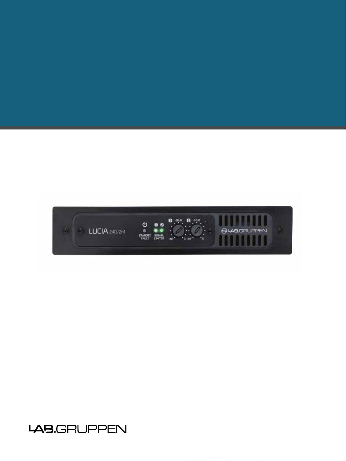
LUCIA®
Compact installation amplifiers
Operation Manual
Page 2
1. Important safety instructions
LUCIA Operation Manual rev 1.2.0
3
3.2 Warnings
apparatus to rain or moisture.
Français: Pour réduire les risques d’incendie ou de choc
électrique, n’exposez pas l’appareil à la pluie ou à l’humidité.
Do not expose this system/apparatus to dripping or splashing
are placed on the apparatus.
Français: N’exposez pas ce système/appareil au
ruissellement ni aux éclaboussures et assurez-vous qu’aucun
objet contenant du liquide tel qu’un vase n’est placé sur
l’appareil.
This apparatus must be connected to a mains socket outlet
with a protective earthing connection.
Français: Cet appareil doit être raccordé à une prise secteur
avec terre de protection.
The mains plug is used as a disconnect device and shall
remain readily operable.
Français:
déconnexion et doit rester constamment accessible.
To prevent electric shock do not remove top or bottom covers.
service personnel.
Français: Pour prévenir un choc électrique, ne retirez pas
les capots du dessus et du dessous. Aucune pièce n’est
To completely disconnect this equipment from the AC mains,
disconnect the power supply cord plug from the AC receptacle.
The mains plug of the power supply cord shall remain readily
operable.
Français: Pour totalement isoler l’équipement de l’alimentation
secteur, débranchez le cordon d’alimentation de son
accessible.
Français
Check the voltage in your area and use the correct type of mains
connector.
Français
Please refer to the following table:
110-125 V (US)
UL817 and CSA C22.2 no 42.
220 -230 V (EUROPE)
CEE 7 page VII, SR section 107-2-D1/
IEC 83 page C4
240 V (U K)
13 A fused plugs and switched and
unswitched socket outlets.
Voltage Line plug (accor ding to standard)
3.3 User responsibility
3.1.1 Mains connection grounding
3.1.2 Speaker output hazard
voltages. To avoid electrical shock, do not touch any exposed
connected to the speaker terminals shall be installed by a
voltage, do not connect or disconnect speaker cables when
the mains power is on.
3.1.3 Radio interference
A sample of this product has been tested and complies with
the limits for the European Electro Magnetic Compatibility
(EMC) directive. It also has been tested and found to comply
with the limits for a Class A digital device, pursuant to Part
15 of the FCC Rules. These limits are designed to provide
reasonable protection against harmful interference from
electrical equipment. This product use
s radio frequency
energy and, if not used or installed in accordance with these
operating instructions, may cause interference to other
equipment, such as radio receivers. However, there is no
guarantee that interference will not occur in a particular
installation. If this equipment causes harmful interference
to radio or television reception (determined by turning the
equipment on and off), the user may be able to correct the
interference by one or more of the following measures:
• Check if
the affected unit complies with the EMC limits for
immunity, (CE-labeled). If not, address the problem with
the manufacturer or supplier. All electrical products
sold in the EC must be approved for immunity against
interference.
• Consult the dealer or an experienced radio/TV technician
for help.
• Reorient or relocate the antenna.
• Increase the separation between the equipment and
receiver.
• Connect the equipment into an outlet on a circuit different
from that to which the receiver is connected.
3.1.4 Speaker damage
3.1.5 Maintenance
For safe and reliable operation, any dust collected in the front
panel should be removed regularly. In rare circumstances,
accumulated dust could ignite due to
high internal
air cannot pass, then the unit will eventually go into thermal
protection; any resultant problems will not be covered by the
warranty.
3. Warnings
Many loudspeakers can be easily damaged or destroyed by
overpowering them. Always check the speaker’s continuous
and peak power capabilities. The low impedance Lucia models
have the ability to set output power limitation, allowing Lucia
output power to be adjusted to ensure that it does not exceed
loudspeaker specifications.
1. Important safety instructions
and the Safety Instructions.
1. Read these instructions.
2. Keep these instructions
3. Heed all warnings.
4. Follow all instructions.
5. Do not use this apparatus near water.
6. Clean only with a dry cloth.
7. Do not block any ventilation openings. Install in accordance
with the manufacturer’s instructions.
8. Do not install near any heat sources such as radiators, heat
produce heat.
9. Do not defeat the safety purpose of the polarized or groundingtype plug. A polarized plug has two blades with one wider
than the other. A grounding-type plug has two blades and
a third grounding prong. The wide blade or the third prong
into your outlet, consult an electrician for replacement of the
obsolete outlet.
10. Protect the power cord from being walked on or pinched,
particularly at plugs, convenience receptacles, and the point
where they exit from the apparatus.
11.
manufacturer.
12.
by the manufacturer, or sold with the apparatus. When a
cart is used, use caution when moving the cart/apparatus
combination to avoid injury from tip-over.
13. Unplug this apparatus during lightning storms or when
unused for long periods of time.
14.
is required when the apparatus has been damaged in any
way, such as power-supply cord or plug is damaged, liquid
has been spilled or objects have fallen into the apparatus, the
apparatus has been exposed to rain or moisture, does not
operate normally, or has been dropped.
2. Approvals
This equipment has been tested and found to comply with the
limits for a Class B Digital device, pursuant to part 15 of the
FCC rules.
These limits are designed to provide reasonable protection
against harmful interference in residential installations. This
equipment generates, uses and can radiate radio frequency
energy and, if not installed and used in accordance with
the instructions, may cause harmful interference to radio
communications. However, there is no guarantee that
Interference will not occur in a particular installation. If this
equipment does cause harmful interference to radio or
television reception, which can be determined by turning the
equipment off and on, the user is encouraged to try to correct
the interference by one or more of the following measures:
• Reorient or relocate the receiving antenna.
• Increase the separation between the equipment
and receiver.
• Connect the equipment into an outlet on a circuit different
from that to which the receiver is connecte
• Consult the dealer or an experienced radio/TV technician
for help.
3. Warnings
3.1 Explanation of warning symbols
For customers in Canada
This Class B digital apparatus complies with Canadian
ICES-003.
Cet appareil numérique de la classe B est conforme à la
norme NMB003 du Canada.
The lightning bolt triangle is used to
alert the user to the presence of
un-insulated “dangerous voltages”
within the unit’s chassis that may be
d.
2
LUCIA Operation Manual rev 1.2.0
risk of electric shock to humans.
The exclamation point triangle is used to
alert the user to presence of important
operating and service instructions in the
literature accompanying the product.
Page 3
LUCIA Operation Manual rev 1.2.0
3
3.2 Warnings
apparatus to rain or moisture.
Français: Pour réduire les risques d’incendie ou de choc
électrique, n’exposez pas l’appareil à la pluie ou à l’humidité.
Do not expose this system/apparatus to dripping or splashing
are placed on the apparatus.
Français: N’exposez pas ce système/appareil au
ruissellement ni aux éclaboussures et assurez-vous qu’aucun
objet contenant du liquide tel qu’un vase n’est placé sur
l’appareil.
This apparatus must be connected to a mains socket outlet
with a protective earthing connection.
Français: Cet appareil doit être raccordé à une prise secteur
avec terre de protection.
The mains plug is used as a disconnect device and shall
remain readily operable.
Français:
déconnexion et doit rester constamment accessible.
To prevent electric shock do not remove top or bottom covers.
service personnel.
Français: Pour prévenir un choc électrique, ne retirez pas
les capots du dessus et du dessous. Aucune pièce n’est
To completely disconnect this equipment from the AC mains,
disconnect the power supply cord plug from the AC receptacle.
The mains plug of the power supply cord shall remain readily
operable.
Français: Pour totalement isoler l’équipement de l’alimentation
secteur, débranchez le cordon d’alimentation de son
accessible.
Français
Check the voltage in your area and use the correct type of mains
connector.
Français
Please refer to the following table:
110-125 V (US)
UL817 and CSA C22.2 no 42.
220 -230 V (EUROPE)
CEE 7 page VII, SR section 107-2-D1/
IEC 83 page C4
240 V (U K)
13 A fused plugs and switched and
unswitched socket outlets.
Voltage Line plug (accor ding to standard)
3.3 User responsibility
3.1.1 Mains connection grounding
3.1.2 Speaker output hazard
voltages. To avoid electrical shock, do not touch any exposed
connected to the speaker terminals shall be installed by a
voltage, do not connect or disconnect speaker cables when
the mains power is on.
3.1.3 Radio interference
A sample of this product has been tested and complies with
the limits for the European Electro Magnetic Compatibility
(EMC) directive. It also has been tested and found to comply
with the limits for a Class A digital device, pursuant to Part
15 of the FCC Rules. These limits are designed to provide
reasonable protection against harmful interference from
electrical equipment. This product use
s radio frequency
energy and, if not used or installed in accordance with these
operating instructions, may cause interference to other
equipment, such as radio receivers. However, there is no
guarantee that interference will not occur in a particular
installation. If this equipment causes harmful interference
to radio or television reception (determined by turning the
equipment on and off), the user may be able to correct the
interference by one or more of the following measures:
• Check if
the affected unit complies with the EMC limits for
immunity, (CE-labeled). If not, address the problem with
the manufacturer or supplier. All electrical products
sold in the EC must be approved for immunity against
interference.
• Consult the dealer or an experienced radio/TV technician
for help.
• Reorient or relocate the antenna.
• Increase the separation between the equipment and
receiver.
• Connect the equipment into an outlet on a circuit different
from that to which the receiver is connected.
3.1.4 Speaker damage
3.1.5 Maintenance
For safe and reliable operation, any dust collected in the front
panel should be removed regularly. In rare circumstances,
accumulated dust could ignite due to
high internal
air cannot pass, then the unit will eventually go into thermal
protection; any resultant problems will not be covered by the
warranty.
3. Warnings
Many loudspeakers can be easily damaged or destroyed by
overpowering them. Always check the speaker’s continuous
and peak power capabilities. The low impedance Lucia models
have the ability to set output power limitation, allowing Lucia
output power to be adjusted to ensure that it does not exceed
loudspeaker specifications.
Page 4

4. Table of Contents
4. Table of Contents
1. Important safety instructions 2
2. Approvals 2
3. Warnings 2
3.1 Explanation of warning symbols 2
3.2 Warnings 3
3.3 User responsibility 3
5. Introduction 6
5.1. Welcome 6
5.2. Features (all LUCIA models) 6
5.3. Additional features on LUCIA 120/2M and 240/2M only 6
5.4. Additional features on LUCIA 60/2, 120/2 and 240/2 only
5.5. Additional features on LUCIA 60/1-70, 120/1-70 and 240/1-70 only
6. Unpacking and visual checks 7
7. Installation 7
7.1. Wall mounting 7
7.2. Rack shelf mounting 7
7.3. Lab.gruppen rack shelf kit 7
8. Cooling and fan operation 8
9. Operating voltage 8
10. Grounding 8
11. Front panel 9
12. Rear panel 10
13. Set-up and operation 12
7
7
13.1. Auto standby / Power-up 12
13.3. GPIO Configuration: Mono high-impedance models 13
13.4. Protection mode 14
LUCIA Operation Manual rev 1.2.0
4
12
Page 5
4. Table of Contents
14. LUCIA application browser 14
14.1. Introduction 14
14.2. Software download and installation 14
14.3. Overview 15
14.4. Factory presets 15
16
16
16
14.5.2.1. Input block 17
14.5.2.2. Matrix block 17
14.5.2.3. Output block 18
14.5.2.4. Control block 19
14.6. Saving and storing custom applications 20
14.6.1. Saving applications 20
14.6.2. Storing and sharing applications 20
14.7. Programming a LUCIA device 20
14.8. Online mode 21
21
15. Appendices 22
15.1. Default configuration for LUCIA base models
15.2. Default configuration for LUCIA M models
15.3. Default configuration for LUCIA 70V models 22
15.4. External control via GPI: Connection and components 22
22
22
15.5. Thermal dissipation 24
15.6.
16. FAQ 32
LUCIA Operation Manual rev 1.2.0
29
5
Page 6

5. Introduction
5. Introduction
5.1. Welcome
outstanding performance, reliable operation and a long service life in any type of commercial sound or general AV
application.
control and I/O are conveniently placed exactly where they are needed. In many AV applications requiring
placement behind video displays. All connections are via Euroblock screw terminals, and level setting is
loudspeakers from potential damage caused by clipping, thermal overload, or extreme low line voltage.
5.2. Features (all LUCIA models)
• Comprehensive DSP features – Per channel presets for high-pass filter, parametric EQ,
multi-band compressor, and look-ahead limiter
• Automatic Dynamic Loudness Contouring™ – DSP automatically adapts to optimize performance
at any output level
• Optimized presets – Available for specific loudspeaker models
• Configuration software – Windows and Mac software wizard for initial set-up, and advanced editor for
preset configuration (LUCIA connection via USB)
• RS232 – Remote control and monitoring from third party control solutions
• GPIO – Remote control (e.g. wall panel) for channel switching, level control and integration with paging systems
• Efficient Class D amplifier – Patented design for low distortion and minimal heat dissipation
• Compact form factor – Half-rack, 1U chassis and supplied bracket for discreet on-wall mounting
(e.g. behind display screens)
• Intelligent fan control – Silent operation at idle and at lower output levels
• Fail-safe operation – Comprehensive short circuit, thermal, and under-voltage protection
• Universal power supply – Operates at 100 - 240 V AC (50 or 60 Hz)
• ENERGY STAR® qualified – Conforms to latest specification energy efficiency standards
5.3. Additional features on LUCIA 60/2M, 120/2M and 240/2M only
• Maximum output power across range of loads – Power output remains constant into 2, 4 or 8 ohms
• Auto Load Sense™ – Proprietary auto-set VPL™ (Voltage Peak Limiter) for optimum performance
with any connected load
• 4 x 4 mix matrix – Route input signals internally to amplifier or to line-level outputs
LUCIA Operation Manual rev 1.2.0
6
Page 7
6. Unpacking and visual checks
5.4. Additional features on LUCIA 60/2, 120/2 and 240/2 only
• Maximum output power across range of loads – Power output remains constant into 2, 4 or 8 ohms
• Auto Load Sense™ – Proprietary auto-set VPL™ (Voltage Peak Limiter) for optimum performance
with any connected load
• 2 x 2 mix matrix – Route input signals internally to either one or both amplifier channels
5.5. Additional features on LUCIA 60/1-70, 120/1-70 and 240/1-70 only
• Model for constant voltage applications – into 70 V/100 V
• 2 x 1 mix matrix – Mix two sources to mono or use for source selection
6. Unpacking and visual checks
condition. If any damage is discovered, please notify the shipping carrier immediately. Save the packing materials
for the carrier’s inspection and for any future shipping.
7. Installation
7.1. Wall mounting
For attaching brackets (marked “B” on the drilling guide; see inside the shipping box) to the wall, please use
are secured properly to the wall. For drywall mounting, use a woodscrew (3.5 mm diameter with 25 mm minimum
reater than 3 kg (e.g. Molly E22412). This
method of mounting is evaluated for North America according to UL/CA60065.
For mounting on surfaces other than drywall, please ensure that the method of mounting is suitable for the wall
material. Also, be certain that the brackets are secured to the wall with the appropriate means to ensure similar
3 mm Torx machine screws.
7.2. Rack shelf mounting
of the three holes in the bottom marked “A” on
the drilling guide (see inside the shipping box). Use a 4 mm diameter machine screw (not supplied), ensuring that
the length of the screw is suitable for the thickness of the shelf. The screws used should not penetrate into the
7.3. Lab.gruppen rack shelf kit
A special dedicated rack mount shelf designed to hold two LUCIA
accessory. It includes all necessary accessories, screws, and mounting instructions.
LUCIA Operation Manual rev 1.2.0
7
Page 8
8. Cooling and fan operation
Fan mode description
Sustainable average
output power
Loudspeaker SPL extra
rel. 1 W sensitivity*
Distance at which you get
the 1 W SPL**
Fan noise at
1 m distance
Low SPL a pplications with proper ven tilati on
(meet ing room s, etc.)
Up to 2x 6 W 7.8 dB 2.5 m Off
Medi um SPL appl icatio ns – whisper m ode
Up to 2x 12 W 10.8 dB 3.5 m << 32 dBA
Maximu m SPL with 120/2
2x 22 W 13.4 dB 4.7 m 33 dBA
Maximu m SPL with 240 /2
2x 44 W 16.2 dB 6.7 m 36 dBA
8. Cooling and fan operation
Table interpretation: In a typical application, if a loudspeaker has a sensitivity of 87 dB SPL at 1 m for 1 W, then the
fan will stay silent for SPL levels up to ~95 dB (87 + 7.8) at 1 m distance from the loudspeaker; at 2.5 m from the
loudspeaker will maintain levels up to 87 dB with the fan off. If the sustained average output is higher, the fan starts
in whisper mode; however, this shouldn’t be an issue as the program SPL is so much higher, likely above 80 dB no
matter where you are in the room.
9. Operating voltage
AC mains from 100 – 240 V at 50 or 60 Hz.
The power receptacle on the rear panel accepts the supplied IEC cord which terminates in a connector
appropriate for the country of sale.
10. Grounding
reasons, never disconnect the earth (ground) pin on the AC power cord. Use balanced input connections to avoid
hum and interference when longer input cables (more than about 1 m/ 39”) are used.
LUCIA Operation Manual rev 1.2.0
8
Page 9
11. Front panel
1 2 3 4
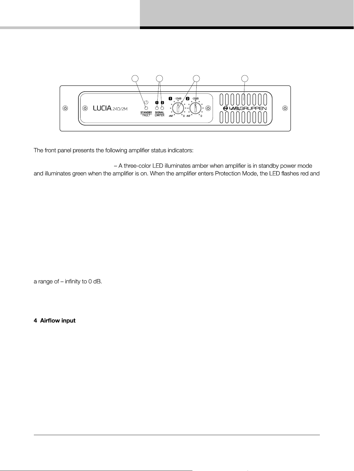
1 Standby/On LED indicator
the speaker outputs are muted. See “Protection mode” in Section 13.3.
11. Front panel
2 Signal present/limit/clip indicators – A three-color LED illuminates to provide channel status information as
follows:
Green – Signal is present at the input and the channel is operating normally.
Amber – Limiting is active on the channel. Limiting is engaged when:
• The channel reaches the voltage limit as determined by the automatic Voltage Peak Limiter (VPL) setting
• Maximum current output is reached
• Mains voltage cannot maintain rail voltage
Red – Channel is clipping either at the input or in DSP
3 Signal attenuators – A signal attenuator is provided for input channels 1 and 2. Attenuators are adjustable over
Note: In LUCIA constant voltage mono models (60/1-70, 120/1-70 and 240/1-70), the attenuators act as an input
select and mixer by adjusting each input level that goes to the single output channel.
– Make certain this input is not blocked or covered.
LUCIA Operation Manual rev 1.2.0
9
Page 10
12. Rear panel
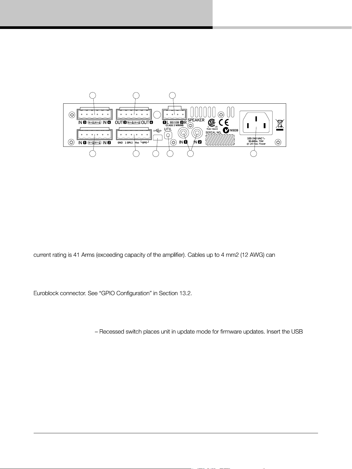
12. Rear panel
12.1. Two output low impedance models: (LUCIA 60/2, 120/2, 240/2, 60/2M, 120/2M, 240/2M)
8 3
1
1 Balanced audio inputs (1 & 2) – Connect balanced inputs using 3-pole Euroblock connectors. Correct polarity
(+, -) and ground terminations are shown on the rear panel. Observe polarity to avoid low frequency cancellation
loss, especially if mixing to mono in in the matrix.
2 Unbalanced audio inputs (1 & 2) – Connect unbalanced inputs (e.g. local video screen output, CD player) to
the RCA (cinch/phono) inputs. Balanced and unbalanced inputs feed an internal analog mixer with optimized gain
settings to ensure that full level can be reached no matter which input is used. A balanced and an unbalanced
input can be connected simultaneously and “the choice of input” is determined by which device
is currently playing.
3 Speaker outputs – Connect loudspeakers with nominal impedance of 2, 4, 8 or 16 ohms. Maximum connector
be accommodated. Observe polarity to avoid low frequency cancellation loss.
Note: Bridge mode connection is not supported.
9
5 74
6 2
4 GPIO/Remote connector – Connect external control and status monitoring devices using the six-pole
5 USB port – Connects to external computer for downloading DSP presets. See “Programming a LUCIA Device”
in Section 14.7. Connection requires cable with a Mini B type connector (included).
6 UTIL (Utility) switch
connector and then push and hold the switch to activate update mode. A red light on the back plate will indicate
that the unit is in update mode.
7 AC line input – Connect the included IEC power cable.
The following features are located on the rear panel of LUCIA 60/2M, 120/2M and 240/2M only:
8 Balanced audio inputs (3 & 4) – Connect balanced inputs using 3-pole Euroblock connectors. Correct polarity
(+, -) and ground terminations are shown on the rear panel.
9 Matrix line outputs – Connect balanced line output cable using 3-pole Euroblock connectors Correct polarity
(+, -) and ground terminations are shown on the rear panel.
LUCIA Operation Manual rev 1.2.0
10
Page 11
12. Rear panel
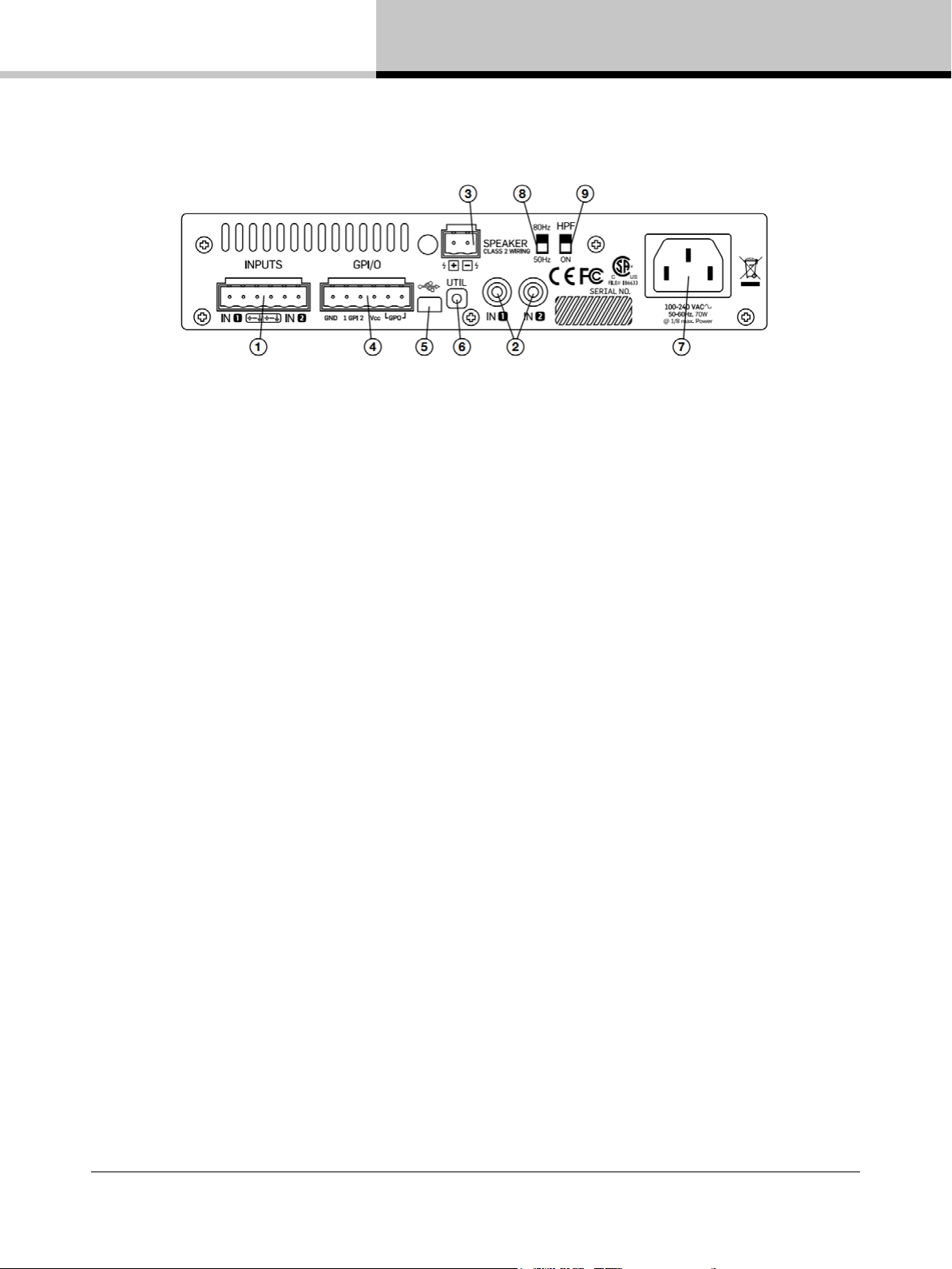
12.2. Mono high-impedance models: (LUCIA 60/1-70, 120/1-70, 240/1-70)
1 Balanced audio inputs (1 & 2) – Connect balanced inputs using 3-pole Euroblock connectors.
Correct polarity (+, -) and ground terminations are shown on the rear panel.
2 Unbalanced audio inputs (1 & 2) – Connect unbalanced inputs (e.g. local video screen output, CD player)
to the RCA (phono) inputs. Note: Balanced and unbalanced inputs are in parallel; only one pair of inputs should be
connected at one time.
3 Speaker outputs – Connect to loudspeakers in a 70 V or 100 V distributed system. Note that if the transformer has marking for 100 V, then the same total power will be delivered as with 70 V. However, since limiting
engages at -3 dB relative to 100 V, the power delivered per loudspeaker will be half of the marking on the
loudspeaker transformer. Consequently, taps should be set to twice the desired power.
4 GPIO/Remote connector – Connect external control and status monitoring devices using the six-pole
Euroblock connector. See “GPIO Configuration” in Set-up and Operation section following.
5 USB port – Connects to external computer for downloading DSP presets. Connection requires cable with a
Mini B type connector (included).
6 UTIL (Utility) switch – Recessed switch places unit in update mode for firmware updates. The switch must be
pushed in and held down while the USB connector is being inserted to activate update mode.
7 AC line input – Connect the included IEC power cable.
8 High pass frequency – Select 80 Hz or 50 Hz for high pass cutoff frequency. This filter is in series with what
gets configured in the Application Browser software.
9 HPF switch – Select ON or bypass for the high pass filter
LUCIA Operation Manual rev 1.2.0
11
Page 12

13. Set-up and operation
13. Set-up and operation
LUCIA Operation Manual rev 1.2.0
13
13.3. GPIO Configuration: Mono high-impedance models
The Default functionality is as described below for General Purpose Inputs and Output (GPIO).
Remote volume control – Connect a remote volume control potentiometer to Ground, GPI1 and Vcc as shown
in the diagram following. Volume control is after input mixing. (The Vcc voltage output is 3.3 V).
Amplifier wake-up – Connect an external contact closure to Ground and GPI2 as shown in the diagram follow-
ing. Wake-up happens within 0.5 s after contact closure.
Amplifier status – Pins 5 and 6 connect to an internal relay to provide amplifier fault indication. The relay is closed
when the amplifier is on and operating normally. The relay opens if a fault in either channel or in the power supply
interrupts normal operation of one or both channels.
Optional GPIO modes – The LUCIA models allow other GPIO functions to be enabled by applying changes to
the amplifier firmware. See “Control block” in Section 14.5.2.4.
13. Set-up and operation
13.1. Auto standby / Power-up
to the unit; it will go into standby mode if no signal is present at any input for 20 minutes. When in standby, the
channel input.
In order to avoid issues with the signal being too low relative the threshold it is generally better to use full level from
the source and to reduce the gain in the LUCIA instead using the front controls, GPI or in the matrix.
13.2. GPIO configuration: Two output impedance models
All low impedance LUCIA models provide the default functionality described below for General Purpose
Inputs and Output (GPIO).
urn on automatically when AC power is connected
reset threshold (-54 dBu) is present at any
Remote volume control – The default functionality for the GPI is independent control of output volume (output 1
on GPI1 and output 2 on GPI2). Please note that this control is in series with the control on the front panel. There
are two ways to do this:
A. Connect a GPO from an external control device with a control voltage output of 0 – 3.3 V. The ground of the
control device must be connected to the ground pin of the LUCIA GPI connector.
B. Connect a remote volume control potentiometer per channel to pins 1 through 4 of the GPIO connector as
shown below. (The VCC voltage output is 3.3 V). If you want the link the control, then you simply link GPI1 and
GPI2 together with a jumper cable.
R
R
Individual volume control
Common volume control
R
interrupts normal operation of one or both channels.
Optional GPIO modes – The LUCIA models allow other GPIO functions to be enabled by applying changes to the
amplifier firmware. See “Control Block” in Section 14.5.2.4.
LUCIA Operation Manual rev 1.2.0
12
Page 13

13. Set-up and operation
13.3. GPIO Configuration: Mono high-impedance models
The Default functionality is as described below for General Purpose Inputs and Output (GPIO).
Remote volume control – Connect a remote volume control potentiometer to Ground, GPI1 and Vcc as shown
in the diagram following. Volume control is after input mixing. (The Vcc voltage output is 3.3 V).
Amplifier wake-up – Connect an external contact closure to Ground and GPI2 as shown in the diagram following. Wake-up happens within 0.5 s after contact closure.
Amplifier status – Pins 5 and 6 connect to an internal relay to provide amplifier fault indication. The relay is closed
when the amplifier is on and operating normally. The relay opens if a fault in either channel or in the power supply
interrupts normal operation of one or both channels.
Optional GPIO modes – The LUCIA models allow other GPIO functions to be enabled by applying changes to
the amplifier firmware. See “Control block” in Section 14.5.2.4.
LUCIA Operation Manual rev 1.2.0
13
Page 14

13. LUCIA application browser
13.4. Protection mode
mode automatically.
IMPORTANT – Protection mode often results from excessive operating levels, improper load conditions or
14. LUCIA application browser
14.1. Introduction
The LUCIA Applciation Browser is a simple, intuitive software editor for configuring the signal matrixing and DSP
features. Amplifier functions are quickly programmed offline and then downloaded to the individual LUCIA units
via the USB port.
Note: Factory presets for common applications include input and matrix settings plus output
equalization pre-optimized for compatible Tannoy loudspeakers and generic loudspeaker types.
All parameters are user adjustable, allowing creation of custom user presets that may be stored
for future use. An online “sync mode” allows real-time setting of parameters – a useful feature for
adjusting loudspeaker response for room acoustics using the four-band parametric equalizers.
14.2. Software download and installation
The LUCIA Application Browser software is available for free download from the Support section of the
Lab.gruppen web site. Select Software & Firmware from the left-hand menu. You must be registered to access
the download pages.
Under LUCIA, select LUCIA Application Browser. Follow the on-screen instructions. Note that there is no separate
(desktop, documents) where write privileges are available.
LUCIA Operation Manual rev 1.2.0
14
Page 15

14.3. Overview
14. LUCIA application browser
one view. The window is divided into three columns:
Application Selector column – The left-hand column lists all application presets currently available for
downloading to LUCIA devices. When created, new user presets are added at the top of the list.
Application View column – The center column shows a graphical representation of the device(s) in the
application preset and the current configuration of inputs, outputs and GPIO together with the option to fetch
current settings from connected LUCIA and enable password protection on settings applied. Multiple LUCIA
devices may be included in a single preset. If more than one device is shown, the device currently selected
for parameter conficuration of downloading of a preset will be shown with a blue frame.
Block Diagram column – The right-hand column displays the various options and tools
the device. Four icons are displayed in a block diagram format: Inputs, Matrix, Outputs and Control. When an icon
lumn below.
14.4. Factory presets
All factory presets are displayed in the Application Selector column. The number of factory presets available will
depend on the version of software installed, as new presets will be added to later versions. Factory presets are
developed by TC Group product specialists to provide quick set-up and optimum performance in a variety of
common AV installations. New users are advised to review all available factory presets to determine which one
custom user preset.
Note: Clicking on the “i” icon at the top of the column opens an information window with a description of the
currently selected preset application. Descriptions also may be added when creating custom user presets.
LUCIA Operation Manual rev 1.2.0
15
Page 16

14. LUCIA application browser
14.5. Application presets: Selection and custom configuration
14.5.1. Configuration in application view
Select the factory application or existing user application that is closest to the requirements of the new application.
If necessary, add one or more additional devices to the application. Parameter presets for multiple units can be
e column to add another device to the application.
Note that saving multiple units as one Application is for user convenience only; parameters for each device must
be downloaded separately.
Select a device for editing. The selected device shows a blue frame.
Name Inputs, Outputs and GPIO connections. Click on the existing name to edit the text.
Using the small “arrow” beside the selected device, it is possible to get settings from the connected LUCIA.
This action can only be performed if the selected configuration model is identical to the connected LUCIA.
By enabling the small “lock” beside the selected device, it is possible to apply a password to protect settings
applied to the connected LUCIA, preventing unauthorized users obtaining knowledge of system configuration.
Note: The password protection only applies when a user tries to get settings from a password protected LUCIA.
So, users are always able to apply new settings to overwrite password protected settings if desired.
14.5.2 Configuration in block diagram view
When a device is selected, the corresponding Application parameters are shown in the Block Diagram view in the
right-hand column. Click on the Input Block, Matrix Block, Output Block or Control Block to edit parameters.
LUCIA Operation Manual rev 1.2.0
16
Page 17

14. LUCIA application browser
14.5.2.1. Input block
speech input (Vocal 100 Hz CUT). A third option (Custom…) allows user configuration of the 4 EQ sections on
each input. Select the option appropriate for your application.
14.5.2.2. Matrix block
The Matrix feature allows any of the inputs to be routed to any output. The level for each matrix route is adjustable
from 0 to -30 dB using the fader to the right of the matrix.
Manual routing – Click in the box to select the desired input-to-output routing.
Preset routing – Matrix settings appropriate for many applications are available as presets using the scroll-down
menu under Presets below the Matrix box.
Level setting – Select the desired matrix route (framed in blue) and use the fader to set the level.
Note: The Matrix selection function is disabled when a GPI function is assigned as Source Selector.
(See Section 14.5.2.4). This prevents possible confusion and errors.
LUCIA Operation Manual rev 1.2.0
17
Page 18

14. LUCIA application browser
14.5.2.3. Output block
the connected loudspeakers.
Factory presets – Presets are provided with output equalization optimized for many Tannoy loudspeakers.
Custom user presets – To create a custom Output preset, scroll to the bottom of the menu and select Custom.
Low Shelve 12 (Shelving boost or cut with 12 dB per octave slope)
Low Shelve 9 (Shelving boost or cut with 9 dB per octave slope)
Low Shelve 6 (Shelving boost or cut with 6 dB per octave slope)
Low Shelve 3 (Shelving boost or cut with 3 dB per octave slope)
Band (normal parametric EQ
High Shelve 3 (Shelving boost or cut with 3 dB per octave slope)
High Shelve 6 (Shelving boost or cut with 6 dB per octave slope)
High Shelve 9 (Shelving boost or cut with 9 dB per octave slope)
High Shelve 12 (Shelving boost or cut with 12 dB per octave slope)
*: If you wish to implement a 24 dB per octave high or low pass
LUCIA Operation Manual rev 1.2.0
18
Page 19

14. LUCIA application browser
be accessible.)
ADLC (Automatic Dynamic Loudness Contouring) – ADLC is a sophisticated, DSP-controlled function that
maintains optimum sound balance regardless of listening level. ADLC may be enabled or disabled using the radio
buttons to the right of each speaker preset.
Adjustable delay – It is possible to add a delay (0-120 ms) to the overall latency on each output.
Adjustable power output – The low impedance LUCIA models enable the option to adjust maximal output power
on each output channel by limiting the maximal peak voltage (Vpk).
14.5.2.4. Control block
function from the MODE menu. The functions available for each port are:
Output Level
Source Selector
Mute All
Wake
RS232
No Function (disabled)
When Wake or Mute functions are selected in MODE, the PRESET box shows a description of the function. These
are described as Open/Close referring to that the only thing needed is a switch connected between GND and the
GPI pin. So, in this scenario Close means that the GPI gets a voltage very close to zero (GND) and Open means
that the voltage is close to Vcc (thanks to an internal connection).
When RS232 is selected, it is possible for third-party products to remote control and monitor LUCIA via RS232 serial
interface. For more information on RS232 serial interface usage, please refer to the “LUCIA Serial Dongle – RS232
Quick Start Guide”, which can be downloaded from http://labgruppen.com/support/download-quick-start-guide
When Source Selector or Output Level functions are selected, available options are shown in the PRESET box.
The GPO is not reconfigurable; the Control Block shows current functionality.
LUCIA Operation Manual rev 1.2.0
19
Page 20

14. LUCIA application browser
14.6. Saving and storing custom applications
14.6.1. Saving applications
The new custom Application will appear at the top of the list in the left-hand column.
IMPORTANT: Do not close the main Application Browser window (quit the program) before saving an Application
14.6.2. Storing and sharing applications
lick on the Save button. A dialog window will
ion of the Application preset. Click on the Save
or from this folder.
14.7. Programming a LUCIA device
Application includes more than one device, select the desired device. It will show with a blue frame.
Connect a USB cable from the computer to the LUCIA device. The PROGRAM button will show as enabled as
soon as the connection is established.
LUCIA Operation Manual rev 1.2.0
20
Page 21

14. LUCIA application browser
Press the Program button
essfully transferred to the device. The dialog also
shows an option to Enable Synchronization. If you want to further edit parameters in real time, click the button and
then click “OK.” (See Online Mode following.) If you do not want to do real-time edits, simply click “OK.”
14.8. Online mode
To enter Online Mode, click the “Enable Synchronization” button when programming a LUCIA device.
(See Section 14.7.)
A device connected in Online Mode shows in the Application Browser with an orange frame.
In Online Mode, any changes made to parameters in the Application Browser are transferred in real time to
the connected LUCIA device. A circular animation shows in the selected device while updating is in progress.
Online Mode is particularly helpful for adjusting output equalization while listening to or measuring the connected
loudspeaker(s).
To exit Online Mode, press the “Sync Enabled” button or select another device.
14.9. Upgrading the firmware in a LUCIA device
application before the application is programmed to the device. If an upgrade is required, then a wizard will guide
this procedure simple and secure.
In the unlikely event that it should fail to update, restart the Application Browser and see what it says; if required put the LUCIA in update mode and try again.
LUCIA Operation Manual rev 1.2.0
21
Page 22

15. Appendices
15. Appendices
15.1. Default configuration for LUCIA base models
RC A
IN 1
BA L
BA L
IN 2
RC A
15.2. Default configuration for LUCIA M models
RC A
IN 1
BA L
BA L
IN 2
RC A
+6 dB
+6 dB
+6 dB
+6 dB
1 2 GPI1 GPI2
SPK 1
SPK 2
1 2 GPI 1 GPI 2
SPK 1
SPK 2
+6 dB
+6 dB
OUT 3
OUT 4
15.3. Default configuration for LUCIA 70V models
15.4. External control via GPI: Connection and components
The default function for GPI is level control, a linear potentiometer with a value between 1 k to 100 k ohm can be
used. As the GPI is internally pulled high it will default to full level if no potentiometer is connected. If the cable is
a shielded twistred pair, then the shield should be connected to ground. Alternately 3 tightly twisted leads can
be used. The potentiometer should be connected so that the wiper (the sliding contact) is at the Vcc side of the
potentiometer for maximum level and at the GND side for Mute.
R
LUCIA Operation Manual rev 1.2.0
22
Page 23

15. Appendices
A resistor ladder selector can be used to perform selection of up to 4 different alternatives. The total impedance
should be between 1k and 100k ohm and one way to do it is as illustrated below (this is also how the Lab.gruppen
accessory is made). Selection and voltages for each of the selected positions is fully configurable.
Position: 1 , 2 , 3 , 4
Vcc
1
GPI
GND
For functions like push to talk and mute all a simple contact closure can be used with LUCIA M. It should be
connected between ground and GPI.
10k10k 10k 10k 10k
2
3
4
LUCIA Operation Manual rev 1.2.0
23
Page 24

15. Appendices
LUCIA Operation Manual rev 1.2.0
25
15. Appendices
LUCIA 60/2
Level Load
Output
power
Mains Watt *1) Thermal Dissipation
VAC
IAC
In Out Dissipated BTU/hr kCal/hr
Standby w. remote Power Off.
230 0,032 0,88 0 1 3 1
120 0,027 0,77 0 1 3 1
100 0,028 0,76 0 1 3 1
Power On, Idling
230 0,12 11,9 0 12 41 10
120 0,19 13,0 0 13 44 11
100 0,22 13,1 0 13 45 11
Pink
pseudo
noise
(1/8)
16 Ω / Ch. 15 x 2
230 0,16 18,6 3,8 15 51 13
120 0,26 18,6 3,8 15 51 13
100 0,30 18,8 3,8 15 51 13
8 Ω / Ch. 30 x 2
230 0,20 23,8 7,5 16 55 14
120 0,32 23,3 7,5 16 54 14
100 0,37 23,7 7,5 16 55 14
4 Ω / Ch. 30 x 2
230 0,20 24,1 7,5 17 57 14
120 0,33 23,9 7,5 16 56 14
100 0,37 24,2 7,5 17 57 14
2 Ω / Ch. 30 x 2
230 0,21 24,8 7,5 17 59 15
120 0,34 24,6 7,5 17 58 15
100 0,39 24,8 7,5 17 59 15
*1) The amplifier’s PSU operates as a non-resistive load, so the calculation “Volts x Amps = Watts” would not be correct. Instead, measured and specified
here is what is known as the “Active Power” in the amplifier providing useful, real-world values of power consumption and heat dissipation.
LUCIA 60/2M
Level Load
Output
power
Mains Watt *1) Thermal Dissipation
VAC IAC
In Out Dissipated BTU/hr kCal/hr
Standby w. remote Power Off.
230 0,032 0,88 0 1 3 1
120 0,027 0,77 0 1 3 1
100 0,028 0,76 0 1 3 1
Power On, Idling
230 0,14 14,8 0 15 51 13
120 0,21 13,4 0 13 46 12
100 0,25 14,1 0 14 48 12
Pink
pseudo
noise
(1/8)
16 Ω / Ch. 15 x 2
230 0,19 21,5 3,8 18 61 15
120 0,27 19,1 3,8 15 52 13
100 0,32 19,9 3,8 16 55 14
8 Ω / Ch. 30 x 2
230 0,23 26,6 7,5 19 65 16
120 0,33 23,7 7,5 16 55 14
100 0,39 24,8 7,5 17 59 15
4 Ω / Ch. 30 x 2
230 0,23 27,0 7,5 19 67 17
120 0,33 24,4 7,5 17 58 15
100 0,39 25,2 7,5 18 60 15
2 Ω / Ch. 30 x 2
230 0,23 27,7 7,5 20 69 17
120 0,35 25,1 7,5 18 60 15
100 0,40 25,9 7,5 18 63 16
*1) The amplifier’s PSU operates as a non-resistive load, so the calculation “Volts x Amps = Watts” would not be correct. Instead, measured and specified
here is what is known as the “Active Power” in the amplifier providing useful, real-world values of power consumption and heat dissipation.
15.5. Thermal dissipation
24
LUCIA Operation Manual rev 1.2.0
Page 25

15. Appendices
15. Appendices
15.4. Thermal dissipation
LUCIA 120/2
Level Load Outpu t power
Mains
volta ge
Line
curr ent
Watt *1) Thermal Diss ipation
VAC IAC In Out
Dissipated
BTU/hr kCal/hr
Standby w. remote Power Off.
230 0.032 0.88 0 1 3 1
120 0.027 0.77 0 1 3 1
100 0.028 0.76 0 1 3 1
Power on, Idling
230 0.21 11.9 0 12 41 10
120 0.19 13.0 0 13 44 11
100 0.22 13.1 0 13 45 11
Pink Ps eudo
Nois e (1/8)
16 Ω / Ch. 30 x 2
230 0.22 25.3 7.5 18 61 15
120 0.34 24.3 7.5 17 57 14
100 0.40 24.6 7.5 17 58 15
8 Ω / Ch. 60 x 2
230 0.30 35.6 15 21 70 18
120 0.47 33.6 15 19 63 16
100 0.54 34.4 15 19 66 17
4 Ω / Ch. 60 x 2
230
0.30 36.3 15 21 73 18
120 0.48 34.9 15 20 68 17
100 0.55 35.3 15 20 69 17
2 Ω / Ch. 60 x 2
230 0.32 37.7 15 23 77 20
120 0.50 36.3 15 21 73 18
100 0.57 36.6 15 22 74 19
*1) The ampli er’s PSU op erates as a non- resistive load, so t he calculatio n “Volts x Amps = Wat ts” would not be corr ect. Instead, me asured and spec i ed here
is what is kn own as the “Active Power” in t he ampli
er providi ng useful, real- world values of power con sumption and heat d issipation.
LUCIA 60/1-70
Level Load Output power Mains Watt *1) Thermal Dissipation
VAC IAC In Out Dissipated BTU/hr kCal/hr
Standby w. remote Power Off.
230 0,032 0,88 0 1 3 1
120 0,027 0,77 0 1 3 1
100 0,028 0,76 0 1 3 1
Power On, Idling
230 0,12 11,9 0 12 41 10
120 0,19 13,0 0 13 44 11
100 0,22 13,1 0 13 45 11
Pink
pseudo
noise
(1/8)
70 V 60 x 1 230 0,20 23,8 15 9 30 8
70 V 60 x 1 120 0,32 23,3 15 8 28 7
70 V 60 x 1 100 0,37 23,7 15 9 30 8
*1) The amplifier’s PSU operates as a non-resistive load, so the calculation “Volts x Amps = Watts” would not be correct. Instead, measured and specified
here is what is known as the “Active Power” in the amplifier providing useful, real-world values of power consumption and heat dissipation.
LUCIA Operation Manual rev 1.2.0
25
Page 26

15. Appendices
LUCIA 120/1-70
Level Load Output power Mains Watt *1) Thermal Dissipation
VAC IAC In Out Dissipated BTU/hr kCal/hr
Standby w. remote Power Off.
230 0,032 0,88 0 1 3 1
120 0,027 0,77 0 1 3 1
100 0,028 0,76 0 1 3 1
Power On, Idling
230 0,12 11,9 0 12 41 10
120 0,19 13,0 0 13 44 11
100 0,22 13,1 0 13 45 11
Pink
pseudo
noise (1/8)
70 V 120 x 1 230 0,30 35,6 15 21 70 18
70 V 120 x 1 120 0,47 33,6 15 19 63 16
70 V 120 x 1 100 0,54 34,4 15 19 66 17
*1) The amplifier’s PSU operates as a non-resistive load, so the calculation “Volts x Amps = Watts” would not be correct. Instead, measured and specified
here is what is known as the “Active Power” in the amplifier providing useful, real-world values of power consumption and heat dissipation.
15. Appendices
15.4. Thermal dissipation
LUCIA 120/2
Level Load Outpu t power
Mains
volta ge
Line
curr ent
Watt *1) Thermal Diss ipation
VAC IAC In Out
Dissi-
pated
BTU/hr kCal/hr
Standby w. remote Power Off.
230 0.032 0.88 0 1 3 1
120 0.027 0.77 0 1 3 1
100 0.028 0.76 0 1 3 1
Power on, Idling
230 0.21 11.9 0 12 41 10
120 0.19 13.0 0 13 44 11
100 0.22 13.1 0 13 45 11
Pink Ps eudo
Nois e (1/8)
16 Ω / Ch. 30 x 2
230 0.22 25.3 7.5 18 61 15
120 0.34 24.3 7.5 17 57 14
100 0.40 24.6 7.5 17 58 15
8 Ω / Ch. 60 x 2
230 0.30 35.6 15 21 70 18
120 0.47 33.6 15 19 63 16
100 0.54 34.4 15 19 66 17
4 Ω / Ch. 60 x 2
230
0.30 36.3 15 21 73 18
120 0.48 34.9 15 20 68 17
100 0.55 35.3 15 20 69 17
2 Ω / Ch. 60 x 2
230 0.32 37.7 15 23 77 20
120 0.50 36.3 15 21 73 18
100 0.57 36.6 15 22 74 19
*1) The ampli er’s PSU op erates as a non- resistive load, so t he calculatio n “Volts x Amps = Wat ts” would not be corr ect. Instead, me asured and spec i ed here
is what is kn own as the “Active Power” in t he ampli
er providi ng useful, real- world values of power con sumption and heat d issipation.
LUCIA 120/2M
Level Load Outpu t power
Mains
volta ge
Line
curr ent
Watt *1) Thermal Diss ipation
VAC IAC In Out
Dissipated
BTU/hr kCal/hr
Standby w. remote Power Off.
230 0.032 0.88 0 1 3 1
120 0.027 0.77 0 1 3 1
100 0.028 0.76 0 1 3 1
Power on, Idling
230 0.14 14.8 0 15 51 13
120 0.21 13.4 0 13 46 12
100 0.25 14.1 0 14 48 12
Pink Ps eudo
Nois e (1/8)
16 Ω / Ch. 30 x 2
230 0.25 28.2 7.5 21 71 18
120 0.35 24.7 7.5 17 59 15
100 0.41 25.6 7.5 18 62 16
8 Ω / Ch. 60 x 2
230 0.33 38.5 15 23 80 20
120 0.47 34.0 15 19 65 16
100 0.55 35.4 15 20 70 18
4 Ω / Ch. 60 x 2
230 0.33 39.2 15 24 83 21
120 0.48 35.3 15 20 69 17
100 0.56 36.3 15 21 73 18
2 Ω / Ch. 60 x 2
230 0.34 40.6 15 26 87 22
120 0.51 36.7 15 22 74 19
100 0.59 37.6 15 23 77 19
*1) The ampli er’s PSU op erates as a non- resistive load, so the c alculation “Vo lts x Amps = Watt s” would not be correc t. Instead, mea sured and speci ed here
is what is kn own as the “Active Power” in the a mpli
er providi ng useful, real- world values of power con sumption and heat d issipation.
15. Appendices
LUCIA Operation Manual rev 1.2.0
27
LUCIA 240/2
Level Load Outpu t power
Mains
volta ge
Line
curr ent
Watt *1) Thermal Diss ipation
VAC IAC IN Out
Dissi-
pated
BTU/hr kCal/hr
Standby w. remote Power Off.
230 0.032 0.88 0 1 3 1
120 0.027 0.77 0 1 3 1
100 0.028 0.76 0 1 3 1
Power on, Idling
230 0.12 11.9 0 12 41 10
120 0.19 13.0 0 13 44 11
100 0.22 13.1 0 13 45 11
Pink Ps eudo
Nois e (1/8)
16 Ω / Ch. 60 x 2
230 0.29 34.4 15 19 66 17
120 0.47 34.7 15 20 67 17
100 0.58 34.1 15 19 65 16
8 Ω / Ch. 120 x 2
230 0.42 53.7 30 24 81 20
120 0.70 54.2 30 24 82 21
100 0.81 54.6 30 25 86 21
4 Ω / Ch. 120 x 2
230 0.45 55.2 30 25 86 22
120 0.74 56.7 30 27 91 23
100 0.84 56.8 30 27 91 23
2 Ω / Ch. 120 x 2
230 0.47 59.1 30 29 99 25
120 0.76 58.9
30 29 98 25
100 0.91 61.1 30 31 106 27
*1) The ampli er’s PSU op erates as a non- resistive load, so t he calculatio n “Volts x Amps = Wat ts” would not be corr ect. Instead, me asured and spec i ed here
is what is kn own as the “Active Power” in t he ampli
er providi ng useful, real- world values of power con sumption and heat d issipation.
LUCIA 240/2M
Level Load Outpu t power
Mains
volta ge
Line
curr ent
Watt *1) Thermal Diss ipation
VAC IAC In Out
Dissi-
pated
BTU/hr kCal/hr
Standby w. remote Power Off.
230 0.032 0.88 0 1 3 1
120 0.027 0.77 0 1 3 1
100 0.028 0.76 0 1 3 1
Power on, Idling
230 0.14 14.8 0 15 51 13
120 0.21 13.4 0 13 46 12
100 0.25 14.1 0 14 48 12
Pink Ps eudo
Nois e (1/8)
16 Ω / Ch. 60 x 2
230 0.31 37.3 15 22 76 19
120 0.48 35.1 15 20 69 17
100 0.60 35.1 15 20 69 17
8 Ω / Ch. 120 x 2
230 0.45 56.6 30 27 91 23
120 0.71 54.6 30 25 84 21
100 0.83 55.6 30 26 87 22
4 Ω / Ch. 120 x 2
230 0.47 58.1 30 28 96 24
120 0.75 57.1 30 27 92 23
100 0.86 57.8 30 28 95 24
2 Ω / Ch. 120 x 2
230 0.49 62.0 30 32 109 28
120 0.77 59.3 30 29 100 25
100 0.93 62.1 30 32 110 28
*1) The ampli er’s PSU op erates as a non- resistive load, so the c alculation “Vo lts x Amps = Watt s” would not be correc t. Instead, mea sured and speci ed here
is what is kn own as the “Active Power” in the a mpli
er providi ng useful, real- world values of power con sumption and heat d issipation.
LUCIA Operation Manual rev 1.2.0
26
Page 27

15. Appendices
LUCIA 240/2
Level Load Outpu t power
Mains
volta ge
Line
curr ent
Watt *1) Thermal Diss ipation
VAC IAC IN Out
Dissipated
BTU/hr kCal/hr
Standby w. remote Power Off.
230 0.032 0.88 0 1 3 1
120 0.027 0.77 0 1 3 1
100 0.028 0.76 0 1 3 1
Power on, Idling
230 0.12 11.9 0 12 41 10
120 0.19 13.0 0 13 44 11
100 0.22 13.1 0 13 45 11
Pink Ps eudo
Nois e (1/8)
16 Ω / Ch. 60 x 2
230 0.29 34.4 15 19 66 17
120 0.47 34.7 15 20 67 17
100 0.58 34.1 15 19 65 16
8 Ω / Ch. 120 x 2
230 0.42 53.7 30 24 81 20
120 0.70 54.2 30 24 82 21
100 0.81 54.6 30 25 86 21
4 Ω / Ch. 120 x 2
230 0.45 55.2 30 25 86 22
120 0.74 56.7 30 27 91 23
100 0.84 56.8 30 27 91 23
2 Ω / Ch. 120 x 2
230 0.47 59.1 30 29 99 25
120 0.76 58.9
30 29 98 25
100 0.91 61.1 30 31 106 27
*1) The ampli er’s PSU op erates as a non- resistive load, so t he calculatio n “Volts x Amps = Wat ts” would not be corr ect. Instead, me asured and spec i ed here
is what is kn own as the “Active Power” in t he ampli
er providi ng useful, real- world values of power con sumption and heat d issipation.
LUCIA 240/2M
Level Load Outpu t power
Mains
volta ge
Line
curr ent
Watt *1) Thermal Diss ipation
VAC IAC In Out
Dissipated
BTU/hr kCal/hr
Standby w. remote Power Off.
230 0.032 0.88 0 1 3 1
120 0.027 0.77 0 1 3 1
100 0.028 0.76 0 1 3 1
Power on, Idling
230 0.14 14.8 0 15 51 13
120 0.21 13.4 0 13 46 12
100 0.25 14.1 0 14 48 12
Pink Ps eudo
Nois e (1/8)
16 Ω / Ch. 60 x 2
230 0.31 37.3 15 22 76 19
120 0.48 35.1 15 20 69 17
100 0.60 35.1 15 20 69 17
8 Ω / Ch. 120 x 2
230 0.45 56.6 30 27 91 23
120 0.71 54.6 30 25 84 21
100 0.83 55.6 30 26 87 22
4 Ω / Ch. 120 x 2
230 0.47 58.1 30 28 96 24
120 0.75 57.1 30 27 92 23
100 0.86 57.8 30 28 95 24
2 Ω / Ch. 120 x 2
230 0.49 62.0 30 32 109 28
120 0.77 59.3 30 29 100 25
100 0.93 62.1 30 32 110 28
*1) The ampli er’s PSU op erates as a non- resistive load, so the c alculation “Vo lts x Amps = Watt s” would not be correc t. Instead, mea sured and speci ed here
is what is kn own as the “Active Power” in the a mpli
er providi ng useful, real- world values of power con sumption and heat d issipation.
LUCIA Operation Manual rev 1.2.0
27
Page 28

15. Appendices
LUCIA 240/1-70
Level Load Output power Mains Watt *1) Thermal Dissipation
VAC IAC In Out Dissipated BTU/hr kCal/hr
Standby w. remote Power Off.
230 0,032 0,88 0 1 3 1
120 0,027 0,77 0 1 3 1
100 0,028 0,76 0 1 3 1
Power On, Idling
230 0,12 11,9 0 12 41 10
120 0,19 13,0 0 13 44 11
100 0,22 13,1 0 13 45 11
Pink pseudo
noise (1/8)
70 V 240 x 1 230 0,42 53,7 30 24 81 20
70 V 240 x 1 120 0,70 54,2 30 24 82 21
70 V 240 x 1 100 0,81 54,6 30 25 84 21
*1) The amplifier’s PSU operates as a non-resistive load, so the calculation “Volts x Amps = Watts” would not be correct. Instead, measured and specified
here is what is known as the “Active Power” in the amplifier providing useful, real-world values of power consumption and heat dissipation.
LUCIA Operation Manual rev 1.2.0
28
Page 29

15. Appendices
15.6. Technical Specifications
General LUCIA 240/2M LUCIA 120/2 M LUCIA 60/2M
Number of powered channels 2 2 2
Total output all channels driven 240 W 120 W 60 W
Max output voltage per channel 1) 43.8 Vpea k 31 Vpe ak 21.9 Vpe ak
Max output current per channel 7.8 Arms 5.5 Arms 3.9 Ar ms
Max Output Power (all channels driven)
2 ohms 120 W 60 W 30 W
4 ohms 120 W 60 W 30 W
8 ohms 120 W 60 W 30 W
16 oh ms 60 W 30 W 15 W
Performa nce
THD 20 Hz - 20 kH z at 1 W into 8 ohms <0.3% <0.3% <0.3%
THD 1kHz and 1 d B below clipping <0.2% <0.2% <0.2%
Signa l to noise ratio i nto 8 ohms >10 1 d BA >98 dBA >95 dBA
Channel separation (Crosstalk) at1 kHz >60 dB >60 dB >60 dB
Frequency response 5 Hz – 22 kHz 5 Hz – 22 kHz 5 Hz – 22 kHz
Input impedance 10 kO hm 10 kO hm 10 kO hm
Input common mode rejection, CMR 40 dB 40 dB 40 dB
Gain, Sensitivity and Limiters
VPL for 16 ohm mo de 44 Vpeak 31 Vpe ak 21.9 Vpe ak
VPL for 8 oh m mode 44 Vpeak 31 Vpe ak 21.9 Vpe ak
VPL for 4 oh m mode 31 Vpe ak 22 Vp eak 15.5 Vpea k
VPL for 2 oh m mode 22 Vpeak 15 Vpe ak 11 Vp ea k
Sensitivity, balanced output 4 dBu / 1.23 Vrms 4 dBu / 1.23 Vrms 4 dBu / 1.23 Vrms
Sensitivity, RCA input -2 dBu / 0.62 Vrms -2 dBu / 0.62 Vrms -2 dBu / 0.62 Vrms
Input h eadroom for c lip, balance d 2) 12 dBu / 3.09 Vrms 12 dBu / 3 .09 Vrms 12 dBu / 3.09 Vrm s
Input h eadroom for c lip, RCA 2) 6 dBu / 1.55 Vrms 6 dBu / 1.55 Vrms 6 dBu / 1.55 Vrms
Connectors and buttons
Input connectors (per channel) 3 - pin detachable screw terminals, electronically balanced
Input c onnectors (c h. 1 & 2) Unbal anced RCA ty pe
Output connectors (per channel) 2 - pin detachable screw terminals
Line- level outpu t connector s (ch. 3 & 4) 3 - pin detachable screw terminals, electronically balanced
GPI (powe r control input) 3) 2 channels o f voltage sen se type. 4 pin s in a detacha ble screw terminal. Defau lt for gain.
GPO (power state outpu t) 3) Contact clo sure type, 2 pi ns in a detach able screw ter minal. Default for exter nal
RS232 Can be co ntrolled an d monitored by t hird parti es via RS232 usi ng both the GPI pins
USB For rmware update and c ongurati on for the matrix models
Level adjustment (p er channe l) 3) Front pan el potentio meter, detented fro m -inf to 0 dB
Matrix model features
Inputs processing block 4) 4 EQ secti ons per inpu t
Mix-matrix routing block 4) 4 in - 4 out mix-matrix control lable from G PI
Output processing block 4) 4 EQ secti ons per outp ut (presets available fo r many louds peakers)
Two line level o utputs 5) Each ca pable of dri ving 6 LUCIA un its in parall el
Latenc y from any inpu t to any output User ad justable f rom 9.15 to 137 ms
Power
Nominal voltage 100 – 240 VAC
Operating voltage 8 5 - 265 VAC
Standby consumption <1 W
Mains connector IEC inle t
Cooling One fan, n o lter requi red, front-to-rear air ow, temperature contro lled spee d. Can stay off i f the
Auto mode The power state is controlled automatically with the audio signal
Dimensions
Weight
Finish
Approvals
Not e 1): Into 8 ohms an d higher
Note 2) : An analog sof t limit will be en gaged on the inp ut above this le vel to reduce the c lip distort ion
Note 3) : Can be congu red for diffe rent functio nality via U SB
Note 4): D SP settings d etermined by s ettings down loaded from t he Applicat ion Browser sof tware; not cong urable on the un it itself
Note 5) : Noise levels t ypically all ow daisy chain ing of 3 LUCIA amp liers with out issues
All sp ecicat ions are su bject to ch ange with out notic e.
sustained power ave rage stays be low 2 x 6 W and the sur rounding te mperature i s below 25 degre es C
monitoring of fault/protection/power off
User adjustable output look ahead limiter
ADLC (Ada ptive ISO 226 com pensatio n)
W: 216 mm (8.5”), H: 44 mm (1.7”), D: 280 mm (11”)
Black aluminium front and black steel chassis
CE, CSA, C CC, PSE, FCC, ENERGY STAR
1.9 kg (4.2 lbs)
LUCIA Operation Manual rev 1.2.0
29
Page 30

15. Appendices
General LUCIA 240/2 LUCIA 120/2 LUCIA 60/2
Number of powered channels 2 2 2
Total output all channels driven 240 W 120 W 60 W
Max output voltage per channel 1) 43.8 Vpe ak 31 Vpe ak 21. 9 Vpe ak
Max output current per channel 7.8 Arms 5.5 Arms 3.9 Arms
Max Output Power (all channels driven)
2 ohms 120 W 60 W 30 W
4 ohms 120 W 60 W 30 W
8 ohms 120 W 60 W 30 W
16 oh ms 60 W 30 W 15 W
Performa nce
THD 20 Hz - 20 kH z at 1 W into 8 ohms <0.3% <0.3% <0.3%
THD 1kHz and 1 d B below clipping <0.2% <0.2% <0.2%
Signa l to noise ratio i nto 8 ohms >10 1 d BA >98 dBA >95 dBA
Channel separation (Crosstalk) at1 kHz >60 dB >60 dB >60 dB
Frequency response 5 Hz – 22 kHz 5 Hz – 22 k Hz 5 Hz – 22 kHz
Input impedance 10 kOhm 10 kO hm 10 k Ohm
Input common mode rejection, CMR 40 dB 40 dB 40 d B
Gain, Sensitivity and Limiters
VPL for 16 ohm mo de 44 Vpeak 31 Vpe ak 21. 9 Vpe ak
VPL for 8 oh m mode 44 Vpeak 31 Vpe ak 21. 9 Vpe ak
VPL for 4 oh m mode 31 Vp eak 2 2 Vpeak 15.5 Vpe ak
VPL for 2 oh m mode 22 Vpea k 15 Vp eak 11 V peak
Sensitivity, balanced output 4 dBu / 1.23 Vrms 4 dBu / 1.23 Vrms 4 dBu / 1.23 Vrms
Sensitivity, RCA input -2 dBu / 0.62 Vrm s -2 dBu / 0.62 Vrms -2 d Bu / 0.62 Vrms
Input h eadroom for c lip, balance d 2) 12 dBu / 3.09 Vrms 12 dBu / 3.09 Vrms 12 dBu / 3.09 Vr ms
Input h eadroom for c lip, RCA 2) 6 dBu / 1.55 Vrms 6 dBu / 1.55 Vrms 6 dBu / 1.55 Vrms
Connectors and buttons
Input connectors (per channel) 3 - pin detachable screw terminals, electronically balanced
Input c onnectors (c h. 1 & 2) Unbalanced RCA type
Output connectors (per channel) 2 - pin detachable screw terminals
GPI (powe r control input) 3) 2 channel s of voltage se nse type. 4 pi ns in a detachable screw ter minal. Defa ult for gain.
GPO (power state outpu t) 3) Contact closure type, 2 p ins in a detachable screw te rminal. Default for exte rnal
RS232 Can be c ontrolled a nd monitored by third part ies via RS232 us ing both the GPI p ins
USB For rm ware update an d congurat ion for the matr ix models
Level adjustment (p er channe l) 3) Front pa nel potentiometer, detented from -inf to 0 dB
Matrix model features
Inputs processing block 4) 4 EQ sections per inp ut
Mix-matrix routing block 4) 2 in - 2 out mix-ma trix contro llable from GPI
Output processing block 4) 4 EQ sections per out put (presets available for many loudspeakers)
Latenc y from any inpu t to any output User adjustable from 9.15 to 137 ms
Power
Nominal voltage 100 – 240 VAC
Operating voltage 85 - 265 VAC
Standby consumption <1 W
Mains connector IEC inl et
Cooling One fa n, no lter requ ired, front-to- rear air ow, tempe rature contr olled spee d. Can stay off i f the
Auto mode The power state is controlled automatically with the audio signal
Dimensions
Weight
Finish
Approvals
Not e 1): Into 8 ohms an d higher
Note 2) : An analog sof t limit will be en gaged on the inp ut above this le vel to reduce the c lip distort ion
Note 3) : Can be congu red for diffe rent functio nality via U SB
Note 4): D SP settings d etermined by s ettings down loaded from t he Applicat ion Browser sof tware; not cong urable on the un it itself
All sp ecicat ions are su bject to ch ange with out notic e.
sustained power ave rage stays be low 2 x 6 W and the sur rounding te mperature i s below 25 degre es C
monitoring of fault/protection/power off
User adjustable output look ahead limiter
ADLC (Ada ptive ISO 226 com pensatio n)
W: 216 mm (8.5”), H: 44 mm (1.7”), D: 280 mm (11”)
Black aluminium front and black steel chassis
CE, CSA, C CC, PSE, FCC, ENERGY STAR
1.9 kg (4.2 lbs)
LUCIA Operation Manual rev 1.2.0
30
Page 31

15. Appendices
General LUC IA 24 0/1-70 LUCI A 120/1-70 LUCI A 60/ 1-70
Number of powered channels 1 1 1
Total output all channels driven 240 W 120 W 60 W
Max output voltage 100 V pe ak 100 V pe ak 100 V pe ak
Max output current 7 Arms 3.5 Arms 1.8 Arm s
Performa nce
70 V 240 W 120 W 60 W
100 V 1) 120 W 6 0 W 30 W
16 ohms 240 W 120 W 60 W
Signa l to Noise Ratio >100 dB A >100 dB A >10 0 dB A
Gain, Sensitivity and Limiters
VPL 100 V peak 100 V peak 100 V pe ak
Sensitivity, balanced output 4 dBu / 1.23 Vrms 4 dBu / 1.23 Vrms 4 dBu / 1.23 Vrms
Sensitivity, RCA input -2 dBu / 0.62 Vrm s -2 dBu / 0.62 Vrms -2 d Bu / 0.62 Vrms
Input h eadroom for c lip, balance d 2) 12 dBu / 3.09 Vrms 12 dBu / 3.09 Vrms 12 dBu / 3.09 Vr ms
Input h eadroom for c lip, RCA 2) 6 dBu / 1.55 Vrms 6 dBu / 1.55 Vrms 6 dBu / 1.55 Vrms
Connectors and buttons
Input connectors (per channel) 3 - pin detachable screw terminals, electronically balanced
Input c onnectors (c h. 1 & 2) Unbalanced RCA type
Output connector 2 - pin detachable screw terminals
GPI (powe r control input) 3) 2 channel s of voltage se nse type. 4 pi ns in a detachable screw ter minal. Defa ult for gain.
GPO (power state outpu t) 3) Contact closure type, 2 p ins in a detachable screw te rminal. Default for exte rnal
RS232 Can be c ontrolled a nd monitored by third part ies via RS232 us ing both the GPI p ins
USB For rm ware update an d congurat ion for the matr ix models
High pa ss lter This lter i s in series wi th the other l ters in the DSP a nd it is contro lled with switches on the back.
Level adjustment (p er input) Front pan el potentio meter, detented fro m -inf to 0 dB
monitoring of fault/protection/power off
Setti ngs OFF / 50 Hz / 80 Hz.
Matrix model features
Inputs processing block 4) 4 EQ sections per inp ut
Mix-matrix routing block 4) 2 in - 1 out mix-ma trix contro llable from GPI
Output processing block 4) 4 EQ sections per out put (presets available for many loudspeakers)
Latenc y from any inpu t to any output User adjustable from 9.15 to 137 ms
Power
Nominal voltage 100 – 240 VAC
Operating voltage 85 - 265 VAC
Standby consumption <1 W
Mains connector IEC inl et
Cooling One fa n, no lter requ ired, front-to- rear air ow, tempe rature contr olled spee d. Can stay off i f the
Auto mode The power state is controlled automatically with the audio signal
Dimensions W: 216 mm (8.5”), H: 44 mm (1.7”), D: 280 mm (11”)
Weight 1.9 kg (4.2 lbs)
Finish Black aluminium front and black steel chassis
Approvals CE, CSA, CCC, PSE, FCC, ENERGY STAR
Not e 1): The pea k voltage is 100 V, but the l ook-ahead lim iter solutio n ensures that i t cannot clip, so i n real life use w ith music or spe ech it will t ypically be a ble to sustain a h igher SPL in
100 V appli cations than 100 V a mpliers w ith higher pe ak voltage ca pability as t he amplie r have the capaci ty to handle pe aks way beyond “cl ip” without so unding hars h.
Note 2) : An analog sof t limit will be en gaged on the inp ut above this le vel to reduce the c lip distort ion
Note 3) : Can be congu red for diffe rent functio nality via U SB
Note 4): D SP settings d etermined by s ettings down loaded from t he Applicat ion Browser sof tware; not cong urable on the un it itself
All sp ecicat ions are su bject to ch ange with out notic e.
sustained power ave rage stays be low 2 x 6 W and the sur rounding te mperature i s below 25 degre es C
User adjustable output look ahead limiter
ADLC (Ada ptive ISO 226 com pensatio n)
LUCIA Operation Manual rev 1.2.0
31
Page 32

16. FAQ
16. FAQ
Is the LUCIA power stage inherently bridged as on E Series, thereby allowing asymmetrical loading?
to use power on one channel that is not being used on the other, as with Lab.gruppen’s E Series. However, the
channels are automatically optimized when it comes to peak voltage, enabling one channel to deliver the full
rated power into 2 ohms and the other channel into 8 ohms.
This is the level at which the input signal will reach full level on the input to the DSP. Above this level, the signal will
be severely compressed by an analog soft-clip circuit.
How many inputs can be driven by a LUCIA M line output?
Each LUCIA balanced line level output can drive up to 6 inputs in parallel; these can be any combination of LUCIA,
ts).
Why is there latency (delay) through LUCIA?
The latency through a LUCIA is 9.15 ms (acoustically equivalent of 10 ft or 3 m). This is primarily due to the lookahead limiters and to the multiband mastering compression used in our ADLC algorithm, which adjusts for the
nonlinearities of the ear (ISO226). The 9.15 ms of latency is below what is detectable as out-of-sync when used in
video sound applications. Nevertheless, in some applications, it is preferable to drive multiple LUCIA units in parallel
ill result in incremental delays.
What limiter circuits are incorporated into LUCIA, and how do they operate?
• Short term (<60 ms), look-ahead voltage peak limiter - The threshold of this limiter is automatically trimmed by
deliver. In LUCIA two output low impedance models, alternate presets may be used that designed for a
lower power output than the full output allowed by the default preset.
• Medium term limiter - This limiter is inserted to avoid clipping if the power supply rail sags.
• Long term (>0.5 s) - This limiter is inserted to prevent thermal problems.
LUCIA Operation Manual rev 1.2.0
32
Page 33

Page 34

labgruppen.com
LUCIATM and Auto Load SenseTM are trademarks of Lab.gruppen AB. All other trademarks remain the property of their respective owners.
Copyright © 2015 MUSIC Group Innovation Sweden AB. All rights reserved.
Item no. OM-LUCIA
 Loading...