

Page 1
LUCIA®
Compact installation amplifiers
Operation Manual
Page 2

1. Important safety instructions
1. Important safety instructions
Before using your LUCIA Series amplier, be sure to carefully read the applicable items of this Operation Manual
and the Safety Instructions.
1. Read these instructions.
2. Keep these instructions
3. Heed all warnings.
4. Follow all instructions.
5. Do not use this apparatus near water.
6. Clean only with a dry cloth.
7. Do not block any ventilation openings. Install in accordance
with the manufacturer’s instructions.
8. Do not install near any heat sources such as radiators, heat
registers, stoves, or other apparatus (including ampliers) that
produce heat.
9. D o no t def e a t th e saf e t y pu r p o s e of th e pola r i z e d or gro u n d i n gtype plug. A polarized plug has two blades with one wider
than the other. A grounding-type plug has two blades and
a third grounding prong. The wide blade or the third prong
is provided for your safety. If the provided plug does not t
into your outlet, consult an electrician for replacement of the
obsolete outlet.
10. Protect the power cord from being walked on or pinched,
particularly at plugs, convenience receptacles, and the point
where they exit from the apparatus.
11. Only use attachments/accessories specied by the
manufacturer.
12. Use only with a cart, stand, tripod, bracket, or table specied
by the manufacturer, or sold with the apparatus. When a
cart is used, use caution when moving the cart/apparatus
combination to avoid injury from tip-over.
13. Unplug this apparatus during lightning storms or when
unused for long periods of time.
14. Refer all servicing to qualied service personnel. Servicing
is required when the apparatus has been damaged in any
way, such as power-supply cord or plug is damaged, liquid
has been spilled or objects have fallen into the apparatus, the
apparatus has been exposed to rain or moisture, does not
operate normally, or has been dropped.
2. Approvals
This equipment has been tested and found to comply with the
limits for a Class B Digital device, pursuant to part 15 of the
FCC rules.
These limits are designed to provide reasonable protection
against harmful interference in residential installations. This
equipment generates, uses and can radiate radio frequency
energy and, if not installed and used in accordance with
the instructions, may cause harmful interference to radio
communications. However, there is no guarantee that
Interference will not occur in a particular installation. If this
equipment does cause harmful inter ference to radio or
television reception, which can be determined by turning the
equipment off and on, the user is encouraged to try to correct
the interference by one or more of the following measures:
• Reorient or relocate the receiving antenna.
• Increase the separation between the equipment
and receiver.
• Connect the equipment into an outlet on a circuit different
from that to which the receiver is connected.
• Consult the dealer or an experienced radio/TV technician
for help.
For customers in Canada
This Class B digital apparatus complies with Canadian
ICES-003.
Cet appareil numérique de la classe B est conforme à la
norme NMB003 du Canada.
3. Warnings
LUCIA Operation Manual rev 1.0.0
2
3.1 Explanation of warning symbols
The lightning bolt triangle is used to
alert the user to the presence of
un-insulated “dangerous voltages”
within the unit’s chassis that may be
of sufcient magnitude to constitute a
risk of electric shock to humans.
The exclamation point triangle is used to
alert the user to presence of important
operating and service instructions in the
literature accompanying the product.
Page 3

110-125 V (US)
UL817 and CSA C22.2 no 42.
220 -230 V (EUROPE)
CEE 7 page VII, S R section 107-2-D1/
IEC 83 page C4.
240 V (U K)
BS 1363 of 1984. Specifi cation for
13 A fused plugs and switched and
unswitched socket outlets.
3. Warnings
3.2 Warnings
To reduce risk of re or electric shock, do not expose this
apparatus to rain or moisture.
Français: Pour réduire les risques d’incendie ou de choc
électrique, n’exposez pas l’appareil à la pluie ou à l’humidité.
Do not expose this system/apparatus to dripping or splashing
and ensure that no objects lled with liquids, such as vases,
are placed on the apparatus.
Français: N’exposez pas ce système/appareil au
ruissellement ni aux éclaboussures et assurez-vous qu’aucun
objet contenant du liquide tel qu’un vase n’est placé sur
l’appareil.
This apparatus must be connected to a mains socket outlet
with a protective earthing connection.
Français: Cet appareil doit être raccordé à une prise secteur
avec terre de protection.
The mains plug is used as a disconnect device and shall
remain readily operable.
Français: La che d’alimentation sert de dispositif de
déconnexion et doit rester constamment accessible.
To prevent electric shock do not remove top or bottom covers.
No user serviceable parts inside. Refer servicing to quali ed
service personnel.
Français: Pour prévenir un choc électrique, ne retirez pas
les capots du dessus et du dessous. Aucune pièce n’est
réparable par l’utilisateur à l’intérieur. Con ez toute réparation
à un personnel de maintenance quali é.
To completely disconnect this equipment from the AC mains,
disconnect the power supply cord plug from the AC receptacle.
The mains plug of the power supply cord shall remain readily
operable.
Français: Pour totalement isoler l’équipement de l’alimentation
secteur, débranchez le cordon d’alimentation de son
embase. La che secteur du cordon d’alimentation doit rester
accessible.
Do not install this device in a con ned space.
Français: N’installez pas cet appareil dans un espace con né.
Check the voltage in your area and use the correct type of mains
connector.
Français: Véri ez la tension en vigueur dans votre région et
utilisez le bon type de che secteur.
Please refer to the following table:
Voltage Line plug (according to standard)
3.3 User responsibility
3.1.1 Mains connection grounding
Your ampli er must be connected to a grounded socket outlet.
3.1.2 Speaker output hazard
Power ampli ers are capable of producing hazardous output
voltages. To avoid electrical shock, do not touch any exposed
speaker wiring while the ampli er is operating. External wiring
connected to the speaker terminals shall be installed by a
quali ed person, or ready-made leads or cords of appropriate
capacity shall be used. As the ampli er outputs produce high
voltage, do not connect or disconnect speaker cables when
the mains power is on.
3.1.3 Radio interference
A sample of this product has been tested and complies with
the limits for the European Electro Magnetic Compatibility
(EMC) directive. It also has been tested and found to comply
with the limits for a Class A digital device, pursuant to Part
15 of the FCC Rules. These limits are designed to provide
reasonable protection against harmful interference from
electrical equipment. This product uses radio frequency
energy and, if not used or installed in accordance with these
operating instructions, may cause interference to other
equipment, such as radio receivers. However, there is no
guarantee that interference will not occur in a particular
installation. If this equipment causes harmful interference
to radio or television reception (determined by turning the
equipment on and off), the user may be able to correct the
interference by one or more of the following measures:
• Check if the affected unit complies with the EMC limits for
immunity, (CE-labeled). If not, address the problem with
the manufacturer or supplier. All electrical products
sold in the EC must be approved for immunity against
electromagnetic elds, high voltage ashes, and radio
interference.
• Consult the dealer or an experienced radio/TV technician
for help.
• Reorient or relocate the antenna.
• Increase the separation between the equipment and
receiver.
• Connect the equipment into an outlet on a circuit different
from that to which the receiver is connected.
3.1.4 Speaker damage
Many loudspeakers can be easily damaged or destroyed by
overpowering them. Always check the speaker’s continuous
and peak power capabilities. Although the ampli er’s
attenuators can be used to reduce the overall gain, an
increase of the input signal can still result in full output power,
which may cause damage to connected speakers.
3.1.5 Maintenance
For safe and reliable operation, any dust collected in the front
panel should be removed regularly. In rare circumstances,
accumulated dust could ignite due to high internal
temperatures and cause a re. If the front is clogged so that
air cannot pass, then the unit will eventually go into thermal
protection; any resultant problems will not be covered by the
wa rr an ty.
LUCIA Operation Manual rev 1.0.0
3
Page 4

4. Table of Contents
4. Table of Contents
1. Important safety instructions 2
2. Approvals 2
3. Warnings 2
3.1 Explanation of warning symbols 2
3.2 Warnings 3
3.3 User responsibility 3
5. Introduction 6
5.1. Welcome 6
5.2. Features (all LUCIA models) 6
5.3. Additional features on LUCIA 120/2M and 240/2M only 6
6. Unpacking and visual checks 7
7. Installation 7
7.1. Wall mounting 7
7.2. Rack shelf mounting 7
7.3. Lab.gruppen rack shelf kit 7
8. Cooling and fan operation 8
9. Operating voltage 8
10. Grounding 8
11. Front panel 9
12. Rear panel 10
13. Set-up and operation 11
13.1. Auto standby / Power-up 11
13.2. GPIO conguration 11
13.3. Protection mode 12
LUCIA Operation Manual rev 1.0.0
4
Page 5

4. Table of Contents
14. LUCIA application browser 12
14.1. Introduction 12
14.2. Software download and installation 12
14.3. Overview 13
14.4. Factory presets 13
14.5. Application presets: Selection and custom conguration 14
14.5.1. Conguration in application view 14
14.5.2 Conguration in block diagram view 14
14.5.2.1. Input block 15
14.5.2.2. Matrix block 15
14.5.2.3. Output block 16
14.5.2.4. Control block 17
14.6. Saving and storing custom applications 18
14.6.1. Saving applications 18
14.6.2. Storing and sharing applications 18
14.7. Programming a LUCIA device 18
14.8. Online mode 19
14.9. Upgrading the rmware in a LUCIA device 19
15. Appendices 20
15.1. Conguration for LUCIA base models 20
15.2. Default conguration for LUCIA M models 20
15.3. External control via GPI: Connection and components 20
15.4. Thermal dissipation 22
15.5. Technical Specications 24
16. FAQ 25
LUCIA Operation Manual rev 1.0.0
5
Page 6

5. Introduction
5. Introduction
5.1. Welcome
Thank you for purchasing a Lab.gruppen LUCIA compact installation amplier. We are condent it will provide
outstanding performance, reliable operation and a long service life in any type of commercial sound or general AV
application.
Lab.gruppen’s innovative LUCIA (Localized Utility Compact Intelligent Amplication) brings superior audio
performance and extraordinary exibility to a decentralized approach in AV systems design. Power, processing,
control and I/O are conveniently placed exactly where they are needed. In many AV applications requiring
consistent, high quality audio output, LUCIA offers a logical, cost-efcient and scalable solution that eliminates the
complications and added expense of a centralized equipment room for amplication, matrixing and processing.
All LUCIA ampliers incorporate a digital, rmware-controlled front end coupled to a robust, durable and highly
efcient Lab.gruppen output stage, all of which make it the best sounding compact amplier in its category.
LUCIA ampliers install quickly and easily, with the supplied wall-mount bracket enabling discreet on-wall
placement behind video displays. All connections are via Euroblock screw terminals, and level setting is
available on front-panel potentiometers. An advanced protection scheme protects the amplier and connected
loudspeakers from potential damage caused by clipping, thermal overload, or extreme low line voltage.
5.2. Features (all LUCIA models)
• Maximum output power across range of loads – Power output remains constant into 2,4 and 8 ohm loads
• Auto Load SenseTM – Proprietary auto-set VPL (Voltage Peak Limiter) for optimum performance with any
connected load
• Efcient Class D amplier – Patented design for low distortion and minimal heat dissipation
• GPIO – Remote control (e.g. wall panel) for channel switching, level control and integration with paging systems
• Compact form factor – Half-rack, 1U chassis and supplied bracket for discreet on-wall mounting
(e.g. behind display screens)
• Fail-safe operation – Comprehensive short circuit, thermal, and under-voltage protection
• Universal power supply – Operates at 100 - 240 V AC (50 or 60 Hz)
• ENERGY STAR® qualied – Conforms to latest specication energy efciency standards
5.3. Additional features on LUCIA 120/2M and 240/2M only
• Comprehensive DSP features – Per channel presets for high-pass lter, parametric EQ, multi-band
compressor, and look-ahead limiter
• Automatic Dynamic Loudness ContouringTM – DSP automatically adapts to optimize performance at any
output level
• 4 x 4 mix matrix – Enables routing of input signals internally to amplier channels or line-level outputs
• Conguration software – Windows software wizard for initial set-up, and advanced editor for preset
conguration (connection via USB). Work is in progress for Mac and iPAD versions.
• Optimized presets – Available for specic loudspeaker models
LUCIA Operation Manual rev 1.0.0
6
Page 7

6. Unpacking and visual checks
6. Unpacking and visual checks
Every Lab.gruppen amplier is carefully tested and inspected before leaving the factory and should arrive in perfect
condition. If any damage is discovered, please notify the shipping carrier immediately. Save the packing materials
for the carrier’s inspection and for any future shipping.
7. Installation
7.1. Wall mounting
For attaching brackets (marked “B” on the drilling guide; see inside the shipping box) to the wall, please use
appropriate means for mounting to a specied load of 3 kg minimum on each screw. Ensure that all four screws
are secured properly to the wall. For drywall mounting, use a woodscrew (3.5 mm diameter with 25 mm minimum
length) and 4.5 mm drywall plug with specied maximum load of greater than 3 kg (e.g. Molly E22412). This
method of mounting is evaluated for North America according to UL/CA60065.
For mounting on surfaces other than drywall, please ensure that the method of mounting is suitable for the wall
material. Also, be certain that the brackets are secured to the wall with the appropriate means to ensure similar
load condition as specied previously. To attach the wall brackets “B” to your amplier, please use the supplied
3 mm Torx machine screws.
7.2. Rack shelf mounting
The amplier can be mounted to a rack shelf or similar by means of the three holes in the bottom marked “A” on
the drilling guide (see inside the shipping box). Use a 4 mm diameter machine screw (not supplied), ensuring that
the length of the screw is suitable for the thickness of the shelf. The screws used should not penetrate into the
amplier for more than 10-20 mm after mounting.
7.3. Lab.gruppen rack shelf kit
A special dedicated rack mount shelf designed to hold two LUCIA ampliers is available from Lab.gruppen as an
accessory. It includes all necessary accessories, screws, and mounting instructions.
LUCIA Operation Manual rev 1.0.0
7
Page 8

8. Cooling and fan operation
Fan mode description
Sustainable average
output power
Loudspeaker SPL extra
rel. 1 W sensitivity*
Distance at which you get
the 1 W SPL**
Fan noise at
1 m distance
Low SPL a pplica tions wi th prope r ventil ation
(meet ing room s, etc.)
Up to 2x 6 W 7.8 d B 2.5 m Off
Medi um SPL app licati ons – whis per mode
Up to 2x 12 W 10.8 dB 3.5 m << 32 dBA
Maxi mum SPL wi th 120/2
2x 22 W 13.4 d B 4.7 m 33 dBA
Maxi mum SPL wi th 240/2
2x 44 W 16.2 dB 6.7 m 36 dBA
8. Cooling and fan operation
Ensure that there is sufcient open space on at least two ventilating surfaces (top, bottom, front and rear) of the
ampliers to allow for free air ow. Please refer to the Thermal Dissipation Chart (Section 15.4) when installing large
numbers of ampliers in air conditioned spaces.
LUCIA ampliers feature intelligent fan control as shown in the following table.
Table interpretation: In a typical application, if a loudspeaker has a sensitivity of 87 dB SPL at 1 m for 1 W, then the
fan will stay silent for SPL levels up to ~95 dB (87 + 7.8) at 1 m distance from the loudspeaker; at 2.5 m from the
loudspeaker will maintain levels up to 87 dB with the fan off. If the sustained average output is higher, the fan starts
in whisper mode; however, this shouldn’t be an issue as the program SPL is so much higher, likely above 80 dB no
matter where you are in the room.
9. Operating voltage
LUCIA ampliers have a universal power supply that operates on AC mains from 100 – 240 V at 50 or 60 Hz.
The power receptacle on the rear panel accepts the supplied IEC cord which terminates in a connector
appropriate for the country of sale.
10. Grounding
Signal ground is oating via a resistor to chassis, and therefore grounding (earthing) is automatic. For safety
reasons, never disconnect the earth (ground) pin on the AC power cord. Use balanced input connections to avoid
hum and interference when longer input cables (more than about 1 m/ 39”) are used.
LUCIA Operation Manual rev 1.0.0
8
Page 9

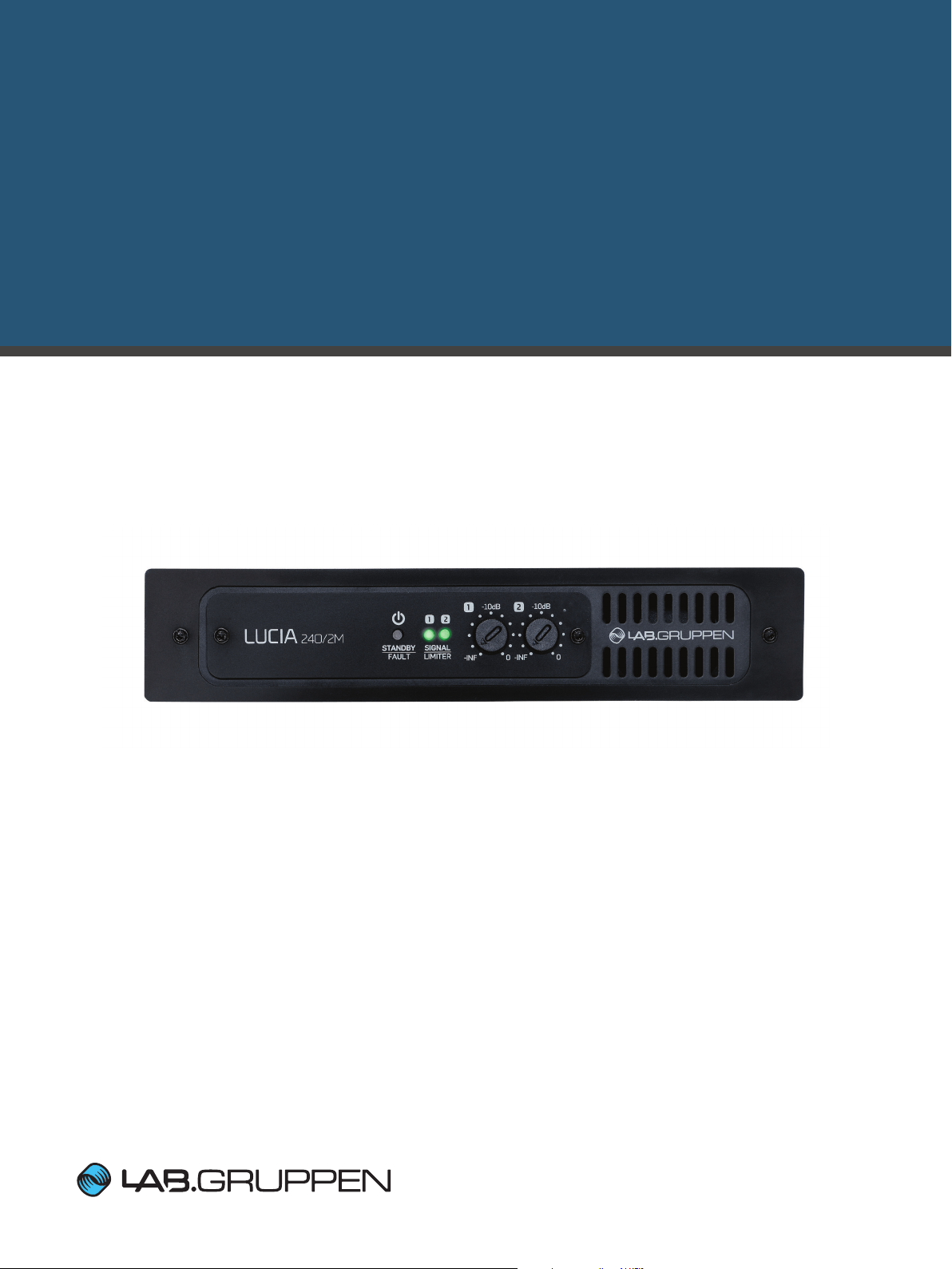
11. Front panel
11. Front panel
1 2 3 4
The front panel presents the following amplier status indicators:
1 Standby/On LED indicator – A three-color LED illuminates amber when amplier is in standby power mode
and illuminates green when the amplier is on. When the amplier enters Protection Mode, the LED ashes red and
the speaker outputs are muted. See “Protection mode” in Section 13.3.
2 Signal present/limit/clip indicators – A three-color LED illuminates to provide channel status information as
follows:
Green – Signal is present at the input and the channel is operating normally.
Amber – Limiting is active on the channel. Limiting is engaged when:
• The channel reaches the voltage limit as determined by the automatic Voltage Peak Limiter (VPL) setting
• Maximum current output is reached
• Mains voltage cannot maintain rail voltage
Red – Channel is clipping either at the input or in DSP
3 Signal attenuators – A signal attenuator is provided for input channels 1 and 2. Attenuators are adjustable over
a range of – innity to 0 dB.
4 Airow input – Make certain this input is not blocked or covered.
LUCIA Operation Manual rev 1.0.0
9
Page 10

12. Rear panel
12. Rear panel
8 3
1
The following features (1-7) are located on the rear panel of all LUCIA ampliers:
1 Balanced audio inputs (1 & 2) – Connect balanced inputs using 3-pole Euroblock connectors. Correct polarity
(+, -) and ground terminations are shown on the rear panel. Observe polarity to avoid low frequency cancellation
loss, especially if mixing to mono in in the matrix.
2 Unbalanced audio inputs (1 & 2) – Connect unbalanced inputs (e.g. local video screen output, CD player) to
the RCA (cinch/phono) inputs. Balanced and unbalanced inputs feed an internal analog mixer with optimized gain
settings to ensure that full level can be reached no matter which input is used. A balanced and an unbalanced
input can be connected simultaneously and “the choice of input” is determined by which device
is currently playing.
3 Speaker outputs – Connect loudspeakers with nominal impedance of 2, 4, 8 or 16 ohms. Maximum connector
current rating is 41 Arms (exceeding capacity of the amplier). Cables up to 4 mm2 (12 AWG) can
be accommodated. Observe polarity to avoid low frequency cancellation loss.
Note: Bridge mode connection is not supported.
9
5 74
6 2
4 GPIO/Remote connector – Connect external control and status monitoring devices using the six-pole
Euroblock connector. See “GPIO Conguration” in Section 13.2.
5 USB port – Connects to external computer for downloading DSP presets. See “Programming a LUCIA Device”
in Section 14.7. Connection requires cable with a Mini B type connector (included).
6 UTIL (Utility) switch – Recessed switch places unit in update mode for rmware updates. Insert the USB
connector and then push and hold the switch to activate update mode. A red light on the back plate will indicate
that the unit is in update mode.
7 AC line input – Connect the included IEC power cable.
The following features are located on the rear panel of LUCIA 120/2M and 240/2M only:
8 Balanced audio inputs (3 & 4) – Connect balanced inputs using 3-pole Euroblock connectors. Correct polarity
(+, -) and ground terminations are shown on the rear panel.
9 Matrix line outputs – Connect balanced line output cable using 3-pole Euroblock connectors Correct polarity
(+, -) and ground terminations are shown on the rear panel.
LUCIA Operation Manual rev 1.0.0
10
Page 11

13. Set-up and operation
Individual volume control
R
Common volume control
R
13. Set-up and operation
13.1. Auto standby / Power-up
LUCIA ampliers do not have a power switch. The amplier will turn on automatically when AC power is connected
to the unit; it will go into standby mode if no signal is present at any input for 20 minutes. When in standby, the
amplier will power up in 0.9 seconds when a signal above the preset threshold (-54 dBu default) is present at any
channel input.
In order to avoid issues with the signal being too low relative the threshold it is generally better to use full level from
the source and to reduce the gain in the LUCIA instead using the front controls, GPI or in the matrix.
13.2. GPIO configuration
All LUCIA models provide the default functionality described below for General Purpose Inputs and Output (GPIO).
Remote volume control – The default functionality for the GPI is independent control of output volume (output 1
on GPI1 and output 2 on GPI2). Please note that this control is in series with the control on the front panel. There
are two ways to do this:
A. Connect a GPO from an external control device with a control voltage output of 0 – 3.3 V. The ground of the
control device must be connected to the ground pin of the LUCIA GPI connector.
B. Connect a remote volume control potentiometer per channel to pins 1 through 4 of the GPIO connector as
shown below. (The VCC voltage output is 3.3 V). If you want the link the control, then you simply link GPI1 and
GPI2 together with a jumper cable.
R
Amplier status – Pins 5 and 6 connect to an internal relay to provide amplier fault indication. The relay is closed
when the amplier is on and operating normally. The relay opens if a fault in either channel or in the power supply
interrupts normal operation of one or both channels.
Optional GPIO modes – The Matrix models allow other GPIO functions to be enabled by applying changes to the
amplier rmware. See “Matrix Block” in Section 14.5.2.2.
LUCIA Operation Manual rev 1.0.0
11
Page 12

14. LUCIA application browser
Note: Transfer of preset data is a one way process. Presets can only be downloaded to the LUCIA
13.3. Protection mode
The ampli er enters Protection mode when thermal conditions or current draw exceed safe limits. When the
ampli er cools below the thermal threshold, or nominal load conditions are restored, the ampli er exits Protection
mode automatically.
IMPORTANT – Protection mode often results from excessive operating levels, improper load conditions or
insuf cient ventilation. Always check these conditions any time a LUCIA ampli er enters Protection mode.
14. LUCIA application browser
14.1. Introduction
The LUCIA Application Browser is a simple, intuitive software editor for con guring the signal matrixing and DSP
features of LUCIA matrix models (LUCIA 120/M and 240/M). Ampli er functions are quickly programmed of ine
and then downloaded to the individual LUCIA units via the USB port.
Note: Transfer of preset data is a one way process. Presets can only be downloaded to the LUCIA
device; you cannot upload settings back to the Application Browser. Therefore, if you want to
connect to a device at a later time and make changes, it is important to save the settings in the
computer running the application browser when you program the LUCIA. This way they can be
recalled, edited and downloaded to the LUCIA device at a later time.
Factory presets for common applications include input and matrix settings plus output equalization
pre-optimized for compatible Tannoy loudspeakers and generic loudspeaker types. All parameters
are user adjustable, allowing creation of custom user presets that may be stored for future use. An
online “sync mode” allows real-time setting of parameters – a useful feature for adjusting loudspeaker
response for room acoustics using the four-band parametric equalizers.
14.2. Software download and installation
The LUCIA Application Browser software is available for free download from the Support section of the
Lab.gruppen web site. Select Software & Firmware from the left-hand menu. You must be registered to access
the download pages.
Under LUCIA, select LUCIA Application Browser. Follow the on-screen instructions. Note that there is no separate
installation wizard. When downloading the compressed (zipped) le, simply save to any convenient location
(desktop, documents) where write privileges are available.
LUCIA Operation Manual rev 1.0.0
12
Page 13

14. LUCIA application browser
14.3. Overview
The LUCIA Application Browser opens to a single main window. All device con guration is accomplished using this
one view. The window is divided into three columns:
Application Selector column – The left-hand column lists all application presets currently available for
downloading to LUCIA devices. When created, new user presets are added at the top of the list.
Application View column – The center column shows a graphical representation of the device(s) in the
application preset and the current con guration of inputs, outputs and GPIO. Multiple LUCIA M Series devices
may be included in a single preset. If more than one device is shown, the device currently selected for parameter
con guration or downloading of a preset will be shown with a blue frame.
Block Diagram column – The right-hand column displays the various options and tools available for con guring
the device. Four icons are displayed in a block diagram format: Inputs, Matrix, Outputs and Control. When an icon
is selected, the applicable con guration tools appear in the column below.
14.4. Factory presets
All factory presets are displayed in the Application Selector column. The number of factory presets available will
depend on the version of software installed, as new presets will be added to later versions. Factory presets are
developed by TC Group product specialists to provide quick set-up and optimum performance in a variety of
common AV installations. New users are advised to review all available factory presets to determine which one
is closest to the requirements of a speci c installation. This will minimize the amount of time required to create a
custom user preset.
Note: Clicking on the “i” icon at the top of the column opens an information window with a description of the
currently selected preset application. Descriptions also may be added when creating custom user presets.
LUCIA Operation Manual rev 1.0.0
13
Page 14

14. LUCIA application browser
14.5. Application presets: Selection and custom confi guration
14.5.1. Confi guration in application view
Select the factory application or existing user application that is closest to the requirements of the new application.
If necessary, add one or more additional devices to the application. Parameter presets for multiple units can be
saved as one application le. Click the “+” at the bottom of the column to add another device to the application.
Note that saving multiple units as one Application is for user convenience only; parameters for each device must
be downloaded separately.
Select a device for editing. The selected device shows a blue frame.
Name Inputs, Outputs and GPIO connections. Click on the existing name to edit the text.
14.5.2 Confi guration in block diagram view
When a device is selected, the corresponding Application parameters are shown in the Block Diagram view in the
right-hand column. Click on the Input Block, Matrix Block, Output Block or Control Block to edit parameters.
LUCIA Operation Manual rev 1.0.0
14
Page 15

14. LUCIA application browser
14.5.2.1. Input block
Each of the four inputs offers an option for either at response (Line) or insertion of a low-cut lter optimized for
speech input (Vocal 100 Hz CUT). Select the option appropriate for your application.
The May 2014 release will offer “Custom” as a third option allowing you to set your own settings for the 4 EQ
sections on each input.
14.5.2.2. Matrix block
The Matrix feature allows any of the four inputs to be routed to any or all of the four outputs: the two loudspeaker
outputs of the ampli er or the two auxiliary line outputs. The level for each output is adjustable from 0 to -30 dB
using the fader to the right of the matrix.
Manual routing – Click in the box to select the desired input-to-output routing.
Preset routing – Matrix settings appropriate for many applications are available as presets using the scroll-down
menu under Presets below the Matrix box.
Level setting – Select the desired output (framed in blue) and use the fader to set the output level.
Note: The Matrix selection function is disabled when a GPI function is assigned as Source Selector.
(See Section 14.5.2.4). This prevents possible confusion and errors.
LUCIA Operation Manual rev 1.0.0
15
Page 16

14. LUCIA application browser
14.5.2.3. Output block
In the Outputs section you can con gure the output processing of individual channels for optimal response from
the connected loudspeakers.
Factory presets – Presets are provided with output equalization optimized for many Tannoy loudspeakers.
Additional presets are provided for generic full-range loudspeakers, with each offering a selection of low-cut lters.
Custom user presets – To create a custom Output preset, scroll to the bottom of the menu and select Custom.
A pop-up window gives access to the output lters that may be customized by the user. For each of the four lter
sections you can select lter type by clicking on the icon. The available lter types are:
Low Cut 12* (second order 12 dB per octave high pass Butterworth lter)
Low Cut 6 ( rst order 6 dB per octave high pass Butterworth lter)
Low Shelve 12 (Shelving boost or cut with 12 dB per octave slope)
Low Shelve 9 (Shelving boost or cut with 9 dB per octave slope)
Low Shelve 6 (Shelving boost or cut with 6 dB per octave slope)
Low Shelve 3 (Shelving boost or cut with 3 dB per octave slope)
Band (normal parametric EQ for which the width is de ned in octaves)
High Shelve 3 (Shelving boost or cut with 3 dB per octave slope)
High Shelve 6 (Shelving boost or cut with 6 dB per octave slope)
High Shelve 9 (Shelving boost or cut with 9 dB per octave slope)
High Shelve 12 (Shelving boost or cut with 12 dB per octave slope)
High Cut 6 ( rst order 6 dB per octave low pass Butterworth lter)
High Cut 12* (second order 12 dB per octave low pass Butterworth lter)
*: If you wish to implement a 24 dB per octave high or low pass Linkwitz-Riley lter,
then simply select two 12 dB lters and set them to the same frequency.
LUCIA Operation Manual rev 1.0.0
16
Page 17

14. LUCIA application browser
Edit the output lters by (as appropriate) selecting an alternative lter type and entering new values in the parameter
boxes. (Only those parameters applicable to the lter type will be accessible.)
To save the custom lter, click on OK. To exit without saving changes, click CANCEL.
ADLC (Automatic Dynamic Loudness Contouring) – ADLC is a sophisticated, DSP-controlled function that
maintains optimum sound balance regardless of listening level. ADLC may be enabled or disabled using the radio
buttons to the right of each speaker preset.
14.5.2.4. Control block
The Control Block allows the user to de ne functions for each of the two GPI ports of the device by selecting a
function from the MODE menu. The functions available for each port are:
Output Level
Source Selector
Mute All
Wake
No Function (disabled)
When Wake or Mute functions are selected in MODE, the PRESET box shows a description of the function. These
are described as Open/Close referring to that the only thing needed is a switch connected between GND and the
GPI pin. So, in this scenario Close means that the GPI gets a voltage very close to zero (GND) and Open means
that the voltage is close to Vcc (thanks to an internal connection).
When Source Selector or Output Level functions are selected, available options are shown in the PRESET box.
The GPO is currently not recon gurable; the Control Block shows current functionality.
LUCIA Operation Manual rev 1.0.0
17
Page 18

14. LUCIA application browser
14.6. Saving and storing custom applications
14.6.1. Saving applications
Once you have completed conguration of a custom Application, click on the Save button. A dialog window will
open which allow you to enter a le name, author and a description of the Application preset. Click on the Save
button in the dialog window to save the Application le.
The new custom Application will appear at the top of the list in the left-hand column.
NOTE: If you click on another Application from the left-hand application menu before saving the le, a prompt will
appear asking if you wish to save the le.
IMPORTANT: Do not close the main Application Browser window (quit the program) before saving an Application
le. The window will close immediately with no prompt, and all entered information will be lost.
14.6.2. Storing and sharing applications
Regardless of the location of the Application Browser (desktop, documents etc.), all Application les will be
stored at C:\Users\username\Documents\LUCIA Applications. Application les may be shared by copying to
or from this folder.
14.7. Programming a LUCIA device
To program a LUCIA device, rst select the desired application from the list in the left-hand column. If the
Application includes more than one device, select the desired device. It will show with a blue frame.
Connect a USB cable from the computer to the LUCIA device. The PROGRAM button will show as enabled as
soon as the connection is established.
LUCIA Operation Manual rev 1.0.0
18
Page 19

14. LUCIA application browser
Press the Program button
A con rmation dialog will show when the settings have been successfully transferred to the device. The dialog also
shows an option to Enable Synchronization. If you want to further edit parameters in real time, click the button and
then click “OK.” (See Online Mode following.) If you do not want to do real-time edits, simply click “OK.”
14.8. Online mode
To enter Online Mode, click the “Enable Synchronization” button when programming a LUCIA device.
(See Section 14.7.)
A device connected in Online Mode shows in the Application Browser with an orange frame.
In Online Mode, any changes made to parameters in the Application Browser are transferred in real time to
the connected LUCIA device. A circular animation shows in the selected device while updating is in progress.
Online Mode is particularly helpful for adjusting output equalization while listening to or measuring the connected
loudspeaker(s).
To exit Online Mode, press the “Sync Enabled” button or select another device.
14.9. Upgrading the fi rmware in a LUCIA device
As features are added, the rmware in the LUCIA will eventually require upgrading. While the LUCIA is connected
to the host computer, the Application Browser will check that the rmware version will support the selected
application before the application is programmed to the device. If an upgrade is required, then a wizard will guide
you through the upgrade procedure with step-by-step instructions. Each step will be veri ed by the wizard to keep
this procedure simple and secure.
In the unlikely event that it should fail to update, restart the Application Browser and see what it says; if required put the LUCIA in update mode and try again.
LUCIA Operation Manual rev 1.0.0
19
Page 20

15. Appendices
IN
1 2 GPI1 GPI2
IN
IN
1 2 GPI 1 GPI 2
IN
15. Appendices
15.1. Configuration for LUCIA base models
RCA
1
BAL
BAL
2
RCA
15.2. Default configuration for LUCIA M models
+6 dB
+6 dB
SPK 1
SPK 2
+6 dB
RCA
1
BAL
BAL
2
RCA
+6 dB
+6 dB
+6 dB
SPK 1
SPK 2
OUT 3
OUT 4
15.3. External control via GPI: Connection and components
The default function for GPI is level control, a linear potentiometer with a value between 1 k to 100 k ohm can be
used. As the GPI is internally pulled high it will default to full level if no potentiometer is connected. If the cable is
a shielded twistred pair, then the shield should be connected to ground. Alternately 3 tightly twisted leads can
be used. The potentiometer should be connected so that the wiper (the sliding contact) is at the Vcc side of the
potentiometer for maximum level and at the GND side for Mute.
R
LUCIA Operation Manual rev 1.0.0
20
Page 21

15. Appendices
Vc
GND
GPI
Position: 1 , 2 , 3 , 4
A resistor ladder selector can be used to perform selection of up to 4 different alternatives. The total impedance
should be between 1k and 100k ohm and one way to do it is as illustrated below (this is also how the Lab.gruppen
accessory is made).
The May 2014 release of the Application Browser software allows customization of selections and voltages for
each of the select positions.
c
1
10k10k 10k 10k 10k
2
3
4
For functions like push to talk and mute all a simple contact closure can be used with LUCIA M. It should be
connected between ground and GPI.
LUCIA Operation Manual rev 1.0.0
21
Page 22

15. Appendices
LUCIA 120/2
Level Load Outp ut power
Mains
voltage
Line
current
Watt *1) Thermal Dissipation
VAC IAC In Out
Dissi
-
pated
BTU/hr kCal/hr
Standby w. remote Power Off.
230 0.032 0.88 0 1 3 1
120 0.027 0.77 0 1 3 1
100 0.028 0.76 0 1 3 1
Power on, Idling
230 0.21 11.9 0 12 41 10
120 0 .19 13.0 0 13 44 11
100 0.22 13.1 0 13 45 11
Pink Ps eudo
Noise (1/8)
16 Ω / Ch. 30 x 2
230 0.22 25.3 7.5 18 61 15
120 0.34 24.3 7. 5 17 57 14
100 0.40 24.6 7.5 17 58 15
8 Ω / Ch. 60 x 2
230 0.30 35.6 15 21 70 18
120 0.47 33.6 15 19 63 16
100 0.54 34.4 15 19 66 17
4 Ω / Ch. 60 x 2
230 0.30 36.3 15 21 73 18
120 0.48 34.9 15 20 68 17
100 0.55 35.3 15 20 69 17
2 Ω / Ch. 60 x 2
230 0.32 37.7 15 23 77 20
120 0.50 36.3 15 21 73 18
100 0.57 36.6 15 22 74 19
*1) The ampli er’s PSU oper ates as a non- resistive load , so the calcula tion “Volts x Amp s = Watts” would not b e correct. Ins tead, measured a nd specied h ere
is what is kn own as the “Active Power ” in the amplier p roviding usefu l, real-wor ld values of power c onsumption and h eat dissipati on.
LUCIA 120/2M
Level Load Output pow er
Mains
voltage
Line
current
Watt *1) Thermal Dissipation
VAC IAC In Out
Dissi
-
pated
BTU/hr kCal/hr
Standby w. remote Power Off.
230 0.032 0.88 0 1 3 1
120 0.027 0.77 0 1 3 1
100 0.028 0.76 0 1 3 1
Power on, Idling
230 0 .14 14.8 0 15 51 13
120 0.21 13.4 0 13 46 12
100 0.25 14.1 0 14 48 12
Pink Ps eudo
Noise (1/8)
16 Ω / Ch. 30 x 2
230 0.25 28.2 7. 5 21 71 18
120 0.35 24.7 7. 5 17 59 15
100 0. 41 25.6 7.5 18 62 16
8 Ω / Ch. 60 x 2
230 0.33 38.5 15 23 80 20
120 0.47 34.0 15 19 65 16
100 0.55 35.4 15 20 70 18
4 Ω / Ch. 60 x 2
230 0.33 39.2 15 24 83 21
120 0.48 35.3 15 20 69 17
100 0.56 36.3 15 21 73 18
2 Ω / Ch. 60 x 2
230 0.34 40.6 15 26 87 22
120 0.51 36.7 15 22 74 19
100 0.59 3 7.6 15 23 77 19
*1) The ampli er’s PSU oper ates as a non- resistive load , so the calcula tion “Volts x Amp s = Watts” would not b e correct. Ins tead, measured a nd specied h ere
is what is kn own as the “Active Power ” in the amplier p roviding usefu l, real-wor ld values of power c onsumption and h eat dissipati on.
15.4. Thermal dissipation
LUCIA Operation Manual rev 1.0.0
22
Page 23

15. Appendices
LUCIA 240/2
Level Load Output pow er
Mains
voltage
Line
current
Watt *1) Thermal Dissipation
VAC IAC In Out
Dissi
-
pated
BTU/hr kCal/hr
Standby w. remote Power Off.
230 0.032 0.88 0 1 3 1
120 0.027 0.77 0 1 3 1
100 0.028 0.76 0 1 3 1
Power on, Idling
230 0 .12 11. 9 0 12 41 10
120 0 .19 13.0 0 13 44 11
100 0.22 13.1 0 13 45 11
Pink Ps eudo
Noise (1/8)
16 Ω / Ch. 60 x 2
230 0.29 34.4 15 19 66 17
120 0.47 3 4.7 15 20 67 17
100 0.58 3 4.1 15 19 65 16
8 Ω / Ch. 120 x 2
230 0.42 53.7 30 24 81 20
120 0.70 54.2 30 24 82 21
100 0.81 54.6 30 25 84 21
4 Ω / Ch. 120 x 2
230 0.45 55.2 30 25 86 22
120 0 .74 56.7 30 27 91 23
100 0.84 56.8 30 27 91 23
2 Ω / Ch. 120 x 2
230 0.47 59.1 30 29 99 25
120 0.76 58.9
30
29 98 25
100 0.91 61.1 30 31 106 27
*1) The ampli er’s PSU oper ates as a non- resistive load , so the calcula tion “Volts x Amp s = Watts” would not b e correct. Ins tead, measured a nd specied h ere
is what is kn own as the “Active Power ” in the amplier p roviding usefu l, real-wor ld values of power c onsumption and h eat dissipati on.
LUCIA 240/2M
Level Load Output pow er
Mains
voltage
Line
current
Watt *1) Thermal Dissipation
VAC IAC In Out
Dissi
-
pated
BTU/hr kCal/hr
Standby w. remote Power Off.
230 0.032 0.88 0 1 3 1
120 0.027 0.77 0 1 3 1
100 0.028 0.76 0 1 3 1
Power on, Idling
230 0 .14 14.8 0 15 51 13
120 0.21 13.4 0 13 46 12
100 0.25 14.1 0 14 48 12
Pink Ps eudo
Noise (1/8)
16 Ω / Ch. 60 x 2
230 0.31 37.3 15 22 76 19
120 0.48 3 5.1 15 20 69 17
100 0.60 3 5.1 15 20 69 17
8 Ω / Ch. 120 x 2
230 0.45 56.6 30 27 91 23
120 0.71 54.6 30 25 84 21
100 0.83 55.6 30 26 87 22
4 Ω / Ch. 120 x 2
230 0.47 58.1 30 28 96 24
120 0.75 5 7.1 30 27 92 23
100 0.86 5 7.8 30 28 95 24
2 Ω / Ch. 120 x 2
230 0.49 62.0 30 32 109 28
120 0.77 59.3
30
29 100 25
100 0.93 6 2.1 30 32 110 28
*1) The ampli er’s PSU oper ates as a non- resistive load , so the calcula tion “Volts x Amp s = Watts” would not b e correct. Ins tead, measured a nd specied h ere
is what is kn own as the “Active Power ” in the amplier p roviding usefu l, real-wor ld values of power c onsumption and h eat dissipati on.
LUCIA Operation Manual rev 1.0.0
23
Page 24

15. Appendices
15.5. Technical Specifications
General LUCIA 2 40/2M LUCIA 120/2M LUCIA 2 40/2 LUCIA 120 /2
Numbe r of powered ch annels 2 2 2 2
Total output all channe ls driven 240 W 120 W 240 W 120 W
Max ou tput voltag e per chann el
Max. output curre nt per chan nel 7.8 Arms 5.5 Arms 7.8 Arms 5.5 Arms
Max. Output Po wer (all ch.’s driven)
2 ohms 120 W 60 W 120 W 60 W
4 ohms 120 W 60 W 120 W 60 W
8 ohms 120 W 60 W 120 W 60 W
16 ohms 60 W 30 W 60 W 30 W
Performa nce
THD 20 Hz - 20 kH z at 1 W into 8 ohms <0.3% <0.3% <0.3% <0.3%
THD at 1 kHZ a nd 1 dB below clipping <0.2% <0.2% <0.2% <0.2%
Signa l to noise ratio into 8 ohms >101 dBA >98 dBA >101 dBA >98 dBA
Chann el separat ion (Crosst alk) at 1 kHz >60 dB >60 d B >60 dB >60 dB
Freque ncy respon se 5 Hz - 22 kHz 5 Hz - 22 kHz 5 Hz - 22 kHz 5 Hz - 22 kHz
Input impedance 10 kOhm 10 kOhm 10 kOhm 10 kOhm
Input c ommon mode r ejection, CMR 40 dB 40 dB 40 dB 40 dB
Gain , Sensit ivity a nd Limit ers
VPL for 16 ohm mode 44 V 31 V 44 V 31 V
VPL for 8 oh m mode 44 V 31 V 44 V 31 V
VPL for 4 oh m mode 31 V 22 V 31 V 22 V
VPL for 2 oh m mode 22 V 15 V 22 V 15 V
Sensitivity, balanced input 4 dBu / 1.23 Vrms 4 dBu / 1.23 Vrms 4 dBu / 1.23 Vrms 4 dBu / 1.23 Vrms
Sensi tivity, RCA inp ut -2 dBu / 0.62 Vrms -2 dBu / 0.62 Vrm s -2 dB u / 0.62 Vrms -2 dBu / 0.62 Vrms
Input h eadroom for c lip, balanc ed
Input h eadroom for c lip, RCA
1)
2)
2)
43.8 V pea k 31.0 V peak 43. 8 V peak 31.0 V peak
12 dBu / 3.09 Vrms 12 dBu / 3.09 Vrms 12 dBu / 3.09 Vr ms 12 dBu / 3.09 Vr ms
6 dBu / 1.55 Vrms 6 dBu / 1.55 Vrms 6 dBu / 1.55 Vrms 6 d Bu / 1.55 Vrms
Conn ectors a nd switc hes
Input c onnectors (per ch.) 3-pin detachable screw termin als, ele ctronica lly bal anced
Input c onnectors (ch 1 & 2) Unbal anced RCA type
Outpu t connectors (per ch.) 2-pin d etachabl e screw terminals
GPI (powe r control in put)
GPO (power state output)
USB For rmware update and congurat ion for the matrix model s
Cooling
Auto mod e The powe r state is cont rolled auto maticall y with the audi o signal
Level adjustment (per channe l)
Matr ix model f eature s
Inputs p rocessi ng block
Mix-matr ix routing b lock
Outpu ts process ing block
Two line level o utputs
Latenc y from any inp ut to any output 9.15 ms
Power
Nominal voltage 100 - 240 VAC
Opera ting voltag e 85 - 265 VAC
Standby consumption <1 W
Mains connector IEC inle t
Dimensions
Weight 1.9 kg (4.2 lbs)
Finish Black aluminum front and black steel chassis
Approvals CE, CSA, C CC, PSE, FCC, ENERGY STAR
Warranty 3 year s, compon ents and f actory wo rkmanship. See ful l warrant y stateme nt.
Note 1): In to 8 ohms and hig her
Note 2) : An analog s oft limit w ill be engag ed on the input above this level to reduce t he clip disto rtion
Note 3) : Can be cong ured for dif ferent fu nctional ity via USB
Note 4) : DSP settings determin ed by settin gs downloaded from the A pplication Browser sof tware; not c ongurab le on the unit i tself
Note 5) : Noise leve ls typica lly allow da isy chaining of 3 LUCIA amp liers wi thout issu es
All sp ecica tions ar e subjec t to chang e withou t notice .
3)
3)
3)
4)
4)
4)
5)
2 chann els of voltag e sense ty pe. 4 pins in a det achable sc rew termina l. Default fo r gain.
Contact closure t ype, 2 pins in a detachable screw terminal. Defaul t for external monitori ng of
One fan, no l ter required, front-to-rear ai row, tempera ture control led speed. Can stay off if the
sustained power aver age stays below 2 x 6 W and the surroundin g temperatur e is below 25 degree s C
Front pan el potentio meter, detented from -inf to 0 dB
Defaul t with 4 param etric EQ for e ach of the 4 inpu t channel s
W: 216 mm (8.5”), H: 44 mm (1.7”), D: 280 mm (11”)
fault/protection/power off
4 in - 4 out mi x-matrix con trollable from GPI
ADLC (Ada ptive ISO 226 compensation)
Each ca pable of dri ving 6 LUCIA un its in paral lel
High pa ss lter
Outpu t EQ
Outpu t look ahead l imiter
LUCIA Operation Manual rev 1.0.0
24
Page 25

16. FAQ
Is the LUCIA power stage inherently bridged as on E Series, thereby allowing asymmetrical loading?
No, the power output limit per channel is xed on LUCIA. The amplier cannot be bridged and there is no way
to use power on one channel that is not being used on the other, as with Lab.gruppen’s E Series. However, the
channels are automatically optimized when it comes to peak voltage, enabling one channel to deliver the full
rated power into 2 ohms and the other channel into 8 ohms.
What is the meaning and importance of “Input headroom for clip” in the technical specications?
This is the level at which the input signal will reach full level on the input to the DSP. Above this level, the signal will
be severely compressed by an analog soft-clip circuit.
How many inputs can be driven by a LUCIA M line output?
Each LUCIA balanced line level output can drive up to 6 inputs in parallel; these can be any combination of LUCIA,
E Series, or C Series ampliers (or other 20 kOhm balanced inputs).
16. FAQ
Why is there latency (delay) through LUCIA?
The latency through a LUCIA is 9.15 ms (acoustically equivalent of 10 ft or 3 m). This is primarily due to the lookahead limiters and to the multiband mastering compression used in our ADLC algorithm, which adjusts for the
nonlinearities of the ear (ISO226). The 9.15 ms of latency is below what is detectable as out-of-sync when used in
video sound applications. Nevertheless, in some applications, it is preferable to drive multiple LUCIA units in parallel
rather than in a series (‘daisy chain’) conguration, as this will result in incremental delays.
What limiter circuits are incorporated into LUCIA, and how do they operate?
Following is a simplied description of the LUCIA limiters:
• Short term (<60 ms), look-ahead voltage peak limiter - The threshold of this limiter is automatically trimmed by
an instantaneous impedance measurement when the amplier goes out of standby. This automatic adjustment
ensures that the threshold does not exceed the rated power or the maximum current that the amplier can
deliver. In LUCIA M models, alternate presets may be used that designed for a lower power output than the full
output allowed by the default preset.
• Medium term limiter - This limiter is inserted to avoid clipping if the power supply rail sags.
• Long term (>0.5 s) - This limiter is inserted to prevent thermal problems.
LUCIA Operation Manual rev 1.0.0
25
Page 26

labgruppen.com
LUCIATM and Auto Load SenseTM are trademarks of Lab.gruppen AB. All other trademarks remain the property of their respective owners.
Copyright © 2014 Lab.gruppen AB. All rights reserved.
Item no. OM-LUCIA
 Loading...