

Page 1
Operation Manual
Lake® LM Series
Digital Audio Processors
Rev 1.2.8
Item: OM-LM
Page 2
Important Safety Instructions
1. Important Safety Instructions
Before using the device, be sure to carefully read the Safety Instruc tions. Keep this document with the device at all times.
1.1 Important Safety Instructions
1. Read these instructions.
2. Keep these instructions.
3. Heed all warnings.
4. Follow all instructions.
5. Do not use this apparatus near water.
6. Clean only with a dry cloth.
7. Do not block any ventilation openings. Install in accordance
with the manufacturer’s instructions.
8. Do not install near any heat sources such as radiators, heat
registers, stoves, or other apparatus (including ampliers)
that produce heat.
9. Do not defeat the safety purpose of the polarized or
grounding-type plug. A polarized plug has two blades with
one wider than the other. A grounding-type plug has two
blades and a third grounding prong. The wide blade or
the third prong is provided for your safety. If the provided
plug does not t into your outlet, consult an electrician for
replacement of the obsolete outlet.
10. Protect the power cord from being walked on or pinched,
particularly at plugs, convenience receptacles, and the point
where they exit from the apparatus.
11. Only use attachments/accessories specied by the
manufacturer.
12. Use only with a cart, stand, tripod, bracket, or table specied
by the manufacturer, or sold with the apparatus. When a
cart is used, use caution when moving the car t/apparatus
combination to avoid injury from tip-over.
13. Unplug this apparatus during lightning storms or when
unused for long periods of time.
14. Refer all servicing to qualied service personnel. Servicing
is required when the apparatus has been damaged in any
way, such as power-supply cord or plug is damaged, liquid
has been spilled or objects have fallen into the apparatus, the
apparatus has been exposed to rain or moisture, does not
operate normally, or has been dropped.
15. Use the mains plug to disconnect the apparatus from the
mains.
16. WARNING: To reduce the risk of re of electric shock, do not
expose this apparatus to rain or moisture.
17. Do not expose this equipment to dripping or splashing and
ensure that no objects lled with liquids, such as vases, are
placed on the equipment.
18. The mains plug of the power supply cord shall remain readily
operable.
19. Do not connect the unit’s output to any other voltage source,
such as battery, mains source, or power supply, regardless
of whether the unit is turned on or off.
20. Do not remove the top (or bottom) cover. Removal of the
cover will expose hazardous voltages. There are no user
serviceable par ts inside and removal may void the warranty.
21. An experienced user shall always supervise this professional
audio equipment, especially if inexperienced adults or
minors are using the equipment.
22. The US National Differences clause 16.3 requires that
network cables must be ame rated V W-1.
To prevent electric shock do not remove top or bottom covers.
No user serviceable parts inside, refer servicing to qualied
service personnel.
À prévenir le choc électrique n’enlevez pas les couvercles. Il n’y a
pas des parties serviceable à l’intérieur, tous reparations doit etre
faire par personnel qualié seulment.
To completely disconnect this equipment from the AC mains,
disconnect the power supply cord plug from the AC receptacle.
The mains plug of the power supply cord shall remain readily
operable.
Pour démonter complètement l’équipement de l’alimentation
générale, démonter le câble d’alimentation de son réceptacle. La
prise d’alimentation restera aisément fonctionnelle.
1.2 Standards
This equipment conforms to the requirements of the EMC Directive 2004/108/EC
and the requirements of the Low Voltage
Directive 2006/95/EC.
Standards applied: EMC Emission
EN55103 -1, E3
EMC Immunity EN55103-2, E3, with S/N
below 1% at normal operation level.
Electrical Safety EN60 06 5, Class I
This equipment is tested and listed according to the U.S. safety standard ANSI/ UL
60065 and Canadian safety standard CSA
C22.2 NO. 60065. Intertek made the tests
and they are a Nationally Recognized Testing Laboratory (NRTL).
1.3 Explanation of Graphical Symbols
The lightning bolt triangle is used to alert the user to
the presence of un -insulated “dangerous voltages”
within the unit’s chassis that may be of sufcient
magnitude to constitute a risk of electric shock to
humans.
The exclamation point triangle is used to alert the
user to presence of important operating and service
instructions in the literature accompanying the
product.
Lake LM Series Operation Manual Rev 1.2.8
i
Page 3
Important Safety Instructions
1.4 WARNING
To reduce risk of re or electric shock, do not expose this apparatus to rain or moisture.
Pour réduire les risques de blessure ou le choc électrique, n’exposez pas l’appareil à la pluie ou à l’ humidité.
Do not expose this system/apparatus to dripping or splashing and ensure that no objects lled with liquids, such
as vases, are placed on the apparatus.
L’appareil ne doit pas être exposé à des egouttements d’eau ou des éclaboussures et de plus qu’aucun objet
rempli de liquide tel que des vases ne doit pas être placé sur l’appareil.
This apparatus must be connected to a mains socket outlet with a protective earthing connection.
Cet appareil doi t être raccordé á une prise de courant qui est branchée à la terre.
The mains plug is used as a disconnect device and shall remain readily operable.
Lorsque la prise du réseau d’alimentation est utilisés comme dispositif de déconnexion, ce dispositif doit
demeuré aisément accessible.
1.5 CAUTION
To reduce the risk of re or electric shock, do not remove screws. No user-ser viceable parts inside.
Refer servicing to qualied service personnel.
Pour réduire le risque d’incendie ou de choc électrique, ne pas retirer les vis. Aucune pièce réparable par
l’utilisateur. Coner l’entretien àpersonnel qualié.
1.6 FCC Compliance Notice (Radio Interference)
A sample of this product has been tested and complies with the limits for the European Electro Magnetic
Compatibility (EMC) directive. This equipment has also been tested and found to comply with the limits for a
Class B digital device, pursuant to Part 15 of the FCC Rules. These limits are designed to provide reasonable
protection against harmful interference from electrical equipment. This product uses radio frequency energy
and if not used or installed in accordance with these operating instructions, may cause interference to other
equipment, such as radio receivers.
However, there is no guarantee that interference will not occur in a particular installation. If this equipment
does cause harmful interference to radio or television reception, which can be determined by turning the
equipment on and off, the user is encouraged to try to correct the interference by one or more of the
following measures:
▸ Reorient or relocate the antenna.
▸ Increase the separation between the equipment and receiver.
▸ Connect the equipment to an outlet on a circuit different from that to which the receiver is connected.
ii
Lake LM Series Operation Manual Rev 1.2.8
Page 4

Important Safety Instructions
▸ Check if the affected unit complies with the EMC limits for immunity, (CE-labeled). If not, address the
problem with the manufacturer or supplier. All electrical products sold in the EC must be approved for
immunity against electromagnetic elds, high voltage ashes, and radio interference.
▸ Consult the dealer or an experienced radio/ T V technician for help.
1.7 User Responsibility
1.7.1 Mains Connection Grounding
Your apparatus must be connected to a grounded socket outlet.
1.7.2 Maintenance
For safe and reliable operation, the dust lter on the right-hand side air intake should be removed and
cleaned regularly to ensure maximum airow through the device.
If the dust lter is not maintained there will be safety risks; for example, high internal temperatures
could ignite the dust and start a re. There is also a risk that the unit will malfunction since it is dependent
on constant airow from left to right. If the dust lter is not clean and the unit malfunctions, any resulting
problems will not be covered by the warranty.
Lake LM Series Operation Manual Rev 1.2.8
iii
Page 5

Table of Contents
1. Important Safety Instructions ................................................................................................................i
1.1 Important Safety Instructions ............................................................................................................... i
1.2 Standards ..............................................................................................................................................i
1.3 Explanation of Graphical Symbols ......................................................................................................... i
1.4 WARNING ............................................................................................................................................ ii
1.5 CAUTION ............................................................................................................................................. ii
1.6 FCC Compliance Notice (Radio Interference) ....................................................................................... ii
1.7 User Responsibility ..............................................................................................................................iii
2. Welcome ...................................................................................................................................................1
2.1 Introduction .........................................................................................................................................1
2.2 Main Features ......................................................................................................................................1
2.3 Additional Documentation ....................................................................................................................2
3. Installation ................................................................................................................................................ 3
3.1 Unpacking ............................................................................................................................................3
3.2 Mounting ..............................................................................................................................................3
3.3 Cooling .................................................................................................................................................3
3.4 Operating Voltage ................................................................................................................................4
3.5 Grounding ............................................................................................................................................. 4
4. Product Overview .................................................................................................................................... 5
4.1 Front Panel Overview ........................................................................................................................... 5
4.2 Back Panel Overview ........................................................................................................................... 8
5. Signal Flow and Lake Processing ........................................................................................................ 11
5.1 Signal Flow ........................................................................................................................................ 11
5.2 Lake Processing and Control .............................................................................................................. 13
5.3 Modules and Frames ........................................................................................................................ 13
5.4 Loudspeaker Processor (Contour Mode) Overview ...........................................................................14
5.5 System Equalizer (Mesa Mode) Overview ......................................................................................... 14
5.6 Switching between Contour and Mesa Mode ...................................................................................14
5.7 Files and Presets ................................................................................................................................ 15
6. Front Panel Interface ............................................................................................................................. 16
6.1 Overview ............................................................................................................................................ 16
6.2 Front Panel Key Lock .......................................................................................................................... 17
6.3 Power Button .................................................................................................................................. 17
6.4 Meter Button ..................................................................................................................................... 18
6.5 Menu Button ...................................................................................................................................... 18
6.6 Exit Button
6.7 Dynamic Buttons, Controls and LEDs ................................................................................................ 18
6.8 Module I/O Mute Buttons and LED Meters ....................................................................................... 21
........................................................................................................................................18
iv
Lake LM Series Operation Manual Rev 1.2.8
Page 6

6.9 Meter Mode ....................................................................................................................................... 23
6.10 Menu Mode .......................................................................................................................................25
7. Back Panel Interface .............................................................................................................................. 42
7.1 Analog Inputs and Outputs ................................................................................................................42
7.2 AES3 Digital I/O ................................................................................................................................44
7.3 RJ45 etherCON Network Connections ..............................................................................................45
7.4 GPIO Connection ...............................................................................................................................47
7.5 Universal Power Supply Connection .................................................................................................48
8. Appendix ................................................................................................................................................. 49
8.1 Faults and Warnings Overview ..........................................................................................................49
8.2 Maintenance ......................................................................................................................................50
8.3 Factory Default Settings.....................................................................................................................50
8.4 Glossary of Terms, Acronyms and Abbreviations ..............................................................................51
9. Application Guide ..................................................................................................................................54
9.1 Gain Structure ....................................................................................................................................54
9.2 Gain / Level Optimization ...................................................................................................................55
9.3 Digital Audio Connections ..................................................................................................................55
9.4 Digital Clock Conguration .................................................................................................................57
10. LM 26 Technical Specications ............................................................................................................61
11. LM 44 Technical Specications ............................................................................................................62
12. Warranty and Support ..........................................................................................................................63
12.1 General ..............................................................................................................................................63
12.2 International Warranties .....................................................................................................................63
12.3 Technical Assistance and Service ......................................................................................................63
12.4 Trademarks .........................................................................................................................................64
Lake LM Series Operation Manual Rev 1.2.8
v
Page 7

Welcome
2. Welcome
2.1 Introduction
Thank you for choosing the Lake LM Series of Digital Audio Processors. We are condent that you will be
pleased with the performance, unique features, conguration exibility, reliability, and long-term durability
offered by this product.
For fast installation and use of this product, your welcome package includes a printed copy of the LM Series
Quick Start & Field Reference Guide which contains the information required to safely install the product and
place it in service. Control and editing features are accessible via the front panel interface or via the included
Lake Controller software.
It is recommend that the Quick Start & Field Reference Guide and all product documentation on the
included CD-ROM is reviewed to ensure familiarity with the various conguration and control options.
Thank you again for placing your condence in Lake products.
2.2 Main Features
The LM Series incorporates a number of sophisticated technologies to ensure the best possible performance and many years of reliable operation. The following section summarizes the benets of each feature;
additional information is available in the reference manuals.
2.2.1 Lake Processing and Controller
LM Series devices integrate seamlessly into the Lake Processing environment and are accessible via the
Lake Controller software. Processing modules offer precise settings for gain, delay, crossover settings,
equalization and limiting. Lake processing features incorporated in each module include Raised Cosine
Equalization™, linear phase crossovers, and LimiterMax™ loudspeaker protection. The Super Module feature
allows hardware processing modules in two or more separate devices to function as a single module in the
Lake Controller software. Please refer to the Lake Controller Operation Manual for further information.
2.2.2 Lake Analyzer Bridge
Lake Controller software provides integration with third-party real-time analyzers, providing simultaneous
measurement display and EQ adjustment via the Lake Controller.
The third-party measurement tools that can be integrated via the Analyzer Bridge include:
▸ Smaart Live Version 5.4
▸ Live-Capture Light / Live-Capture Pro
Lake LM Series Operation Manual Rev 1.2.8
1
Page 8

Welcome
Smaart, distributed and supported by Rational Acoustics, provides real-time sound system measurement,
optimization and control. Smaart combines several powerful audio frequency measurement and analysis
tools.
Live-Capture, created by WaveCapture, offers easy-to-use software and measurement tools for sound
engineers, installers, consultants and designers. The Lake Analyzer Bridge in conjunction with Live-Capture
Light provides a completely free spectrum analyzer via your Lake Controller software interface.
2.2.3 Dante™ Audio Network
LM Series devices include Dante digital audio networking as standard. Utilizing the latest advances in
Ethernet technology, Dante offers simplied system conguration and extremely low latency while delivering very high quality uncompressed digital audio across the Lake network. The Zen™ automatic conguration
feature enables plug-and-play setup without third-party DHCP or DNS servers. Dante is compatible with
high-bandwidth networks, allowing large numbers of audio channels to be distributed alongside control and
analyzer data.
2.3 Additional Documentation
This document, the Lake LM Series Operation Manual, serves as the primary reference source for detailed
information on the installation and operation of LM Series devices. It also provides detailed information on
set-up and conguration using the front-panel interface.
If you intend to use the device as part of a networked system, or access features via the Lake Controller,
please refer to the various supporting documents which can be located via these methods:
▸ Start > Programs > Lake Controller > Documentation (after installing Lake Controller software)
▸ On the Installer CD-ROM or the downloaded software installer
▸ Online at: http://labgruppen.com/index.php/products/documentation/
2
Lake LM Series Operation Manual Rev 1.2.8
Page 9

Installation
3. Installation
3.1 Unpacking
Carefully open the shipping carton and check for any damage to the device or the supplied accessories.
Every Lake product is tested and inspected before leaving the factory and should arrive in perfect condition.
If any damage is discovered, please notify the shipping company immediately. Only the consignee may
initiate a claim with the carrier or their insurers for damage incurred during shipping. Save the carton and
packing materials for the carrier’s inspection.
In addition to the Lake LM Series device, the shipping carton include the following items:
▸ Lake LM Series Quick Start & Field Reference Guide
▸ AC mains lead (IEC power cable) with locking connector
▸ AES break-out cable (8-in, 8-out)
▸ Ethernet Cable
▸ Software Installer and Documentation CD-ROM
Please keep the original carton and associated packaging to facilitate shipping of the device should the need
arise.
3.2 Mounting
Airow for cooling the device is from side to side (right-side intake to left-side fan). Please ensure there is
sufcient space each side of the unit to allow airow; the space provided by standard rack-rails should be
sufcient. This device has no top or bottom vents and therefore may be stacked directly on top of each
other.
Sufcient space should be available at the front of the rack to accommodate the handles, and at the rear to
accommodate connectors and cables; allowance must be made for cable or loom bends within a rack.
3.3 Cooling
The Lake LM Series devices use a forced-air cooling system, with airow from right to left. The dust lter
on the air intake (right-side) should be regularly cleaned, especially after exposure to dusty environments, to
ensure the maximum possible airow through the unit.
This device is designed to operate in situations where the ambient temperature is below 55
Automatic actions and warnings occur at following temperature thresholds:
▸ At 40oC (104oF) or less, the fan is OFF
Lake LM Series Operation Manual Rev 1.2.8
o
C (131oF).
3
Page 10
Installation
▸ At more than 40oC (104oF) the fan is ON
▸ At 55oC (131oF) a temperature warning is indicated on the front panel as ‘TEMP WARNING’ and in the
Controller Event Log as ‘Temp warning: DSP area’.
▸ At 70oC (158oF) the device has exceeded the maximum normal operating temperature. This fault is
indicated on the front panel as ‘OVERTEMP’ and in the Controller Event Log as ‘Temp fault: DSP area’.
The Processor will NOT mute or shut down when the
temperature reaches or exceeds 70
sustained performance at this temperature cannot be
guaranteed.
o
C (158 oF), however,
3.4 Operating Voltage
The label above the IEC connector indicates the AC mains voltage range for which the device is approved.
LM Series devices utilize a universal power supply, and will operate within the range 70-265V~50-60Hz :
25W. If the plug on the IEC cable provided is not appropriate for your country, a locally-sourced IEC cable
with the appropriate molded plug should be used. A locking IEC cable is not necessary in order to power the
device, although is essential if locking functionality it required.
Once a suitable AC power supply is connected, the device can be turned on using the front panel power
button. When the device is turned on, the power button LED changes from red (Standby) to green (Active).
3.5 Grounding
Analog inputs and outputs feature Iso-Float™ ground isolation, a technology which combines the benets of
transformer-coupled isolation with the advantages of clean, direct-coupled inputs and outputs.
The audio converters are galvanically isolated, and not connected to the main ground. High-speed transformers and opto-isolators create a barrier between the device and the outside electrical environment.
The Iso-Float feature is activated by default, but
may be disabled via the Lake Controller software,
or via the front panel menu.
Use correctly-shielded balanced audio input connections to minimise hum and interference. Please refer to
section 7.1.5 for further information.
NEVER disconnect the earth (ground) pin on the mains cable (AC power cord).
4
Lake LM Series Operation Manual Rev 1.2.8
Page 11

Product Overview
4. Product Overview
This chapter provides an overview of key features and functionality. For further information please see
chapters 5 to 9 of this Operation Manual.
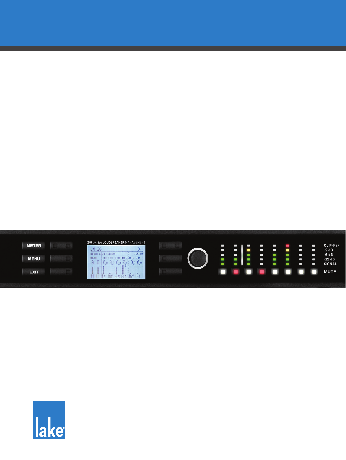
4.1 Front Panel Overview
Figure 4-1: LM Series Front Panel Overview
The front panel controls are clustered around a daylight readable LCD , allowing adjustment and monitoring of the majority parameters and meters. The two clusters of controls on either side of the LCD include
three dedicated function buttons , six dynamic function buttons with embedded LEDs and a
rotary data encoder . To the right of these controls is a dynamic illuminated I/O divider along with input
and output mute buttons and level meters.
Handles
Two sturdy cast aluminium handles are integrated into the front panel. The handles should be used when
carrying the device, and when tting into or removing from a rack. Ensure that any door or removable rack
front cover has sufcient depth to clear the handles.
Standby
LM Series devices are powered on and placed into standby mode using the left-most button, or via the
Lake Controller. Standby mode is not equivalent to turning the device off at the mains power.
All audio in and out of the processor is muted
when in Standby mode. Network communication
remains active to allow the device to be turned on
via the Lake Controller.
Lake LM Series Operation Manual Rev 1.2.8
5
Page 12

Product Overview
Display
The display illuminates when the device is on. The LCD, function buttons, and the rotary encoder provide
real-time control and monitoring of most parameters. The LEDs embedded in the function buttons indicate
available menu options, provide conrmation of Controller communication, and indicate various faults and
warnings.
The brightness and contrast of the display and front panel LEDs can be adjusted via the front panel menu.
Please refer to chapter 6 for further details.
Meter
The METER button scrolls through various meter views including the default Home View, Input Meters View
(Mesa Mode only) and I/O Status View. Pressing METER from Menu Mode returns the screen to Meter
Mode with the Home View displayed. Please refer to section 6.4 for further details.
Menu
After pressing the MENU button, the LCD will display the top level menu. In Menu Mode the dynamic function buttons enable access to various information and functionality. Please refer to section 6.5 for further
details.
Exit
The EXIT button is used primarily while navigating the menu system in Menu Mode; pressing EXIT will
return the menu up one level. In Meter Mode, pressing EXIT returns the metering display to the default
Home View.
Dynamic Function Buttons with LEDs (Left of LCD)
The function of these buttons change according to the currently selected view or menu.
The left LED in the top button illuminates white to indicate the Frame is selected in the Lake Controller, or
ashes white to indicate communication from the Lake Controller. If this button is pressed while in Home
View, and with the Lake Controller on the Home page or the Modules Menu, the associated Module/s of the
selected frame will be highlighted in the Controller (Module A in Contour Mode, or Modules A&B in Mesa
Mode).
The three LEDs on the right side of each button illuminate white when an associated option is available on
the LCD screen.
Please refer to chapter 6 for further details.
6
Lake LM Series Operation Manual Rev 1.2.8
Page 13

Product Overview
Dynamic Function Buttons with LEDs (Right of LCD)
The function of these buttons change according to the currently selected view or menu.
The right bi-color LED in the top button illuminates red or yellow to indicate faults or warnings. If this button
is pressed while in Home View, and with the Lake Controller on the Home page or the Modules Menu, the
associated Module/s of the selected frame will be highlighted in the Controller (Module B in Contour Mode,
or Modules C&D in Mesa Mode).
The three LEDs on the left side of each button illuminate white when an associated option is available on
the LCD screen.
Please refer to chapter 6 for further details.
Rotary Encoder
The rotary encoder is used to modify various parameters (e.g. input level) via the menu. When a menu item
is selected that permits adjustment of parameter values, the ring around the rotary encoder illuminates. In
Home View the encoder can be used to scroll through the Meter Views.
Dynamic Illuminated I/O Divider
The dynamic illuminated divider moves position to indicate the split between inputs and outputs for metering and mute purposes in the two different modes of conguration. Contour Mode provides two Module
inputs, and six Module outputs; Mesa Mode provides four Module inputs and four Module outputs.
The LED meters and mute buttons to the left of the illuminated divider relate to the Module inputs; the LED
meters and mute buttons to the right of the divider relate to the Module outputs.
The I/O divider is not illuminated in I/O Status View as all eight LED meters and associated mute buttons are
used for Input Router signal and mute functionality.
Module Input / Output Mute Buttons and LED Meters
Independent mute buttons and LED meters are provided for the Module inputs and outputs. The number of
inputs and outputs varies depedning on processor and module conguration. Refer to the description above
regarding the Dynamic Illuminated I/O Divider.
The LED meters for each channel are split into ve segments: The bottom three segments (green) indicate
signal; the 4th segment (yellow) indicates signal 2 dB below clipping; and the 5th segment (red) indicates
signal clipping.
The embedded LED in each mute button conrms whether the associated Module input/s or output/s are
muted (red), unmuted (white), associated input router is muted (pink), or unused (not illuminated).
Please refer to section 6.8 for further information.
Lake LM Series Operation Manual Rev 1.2.8
7
Page 14
Product Overview
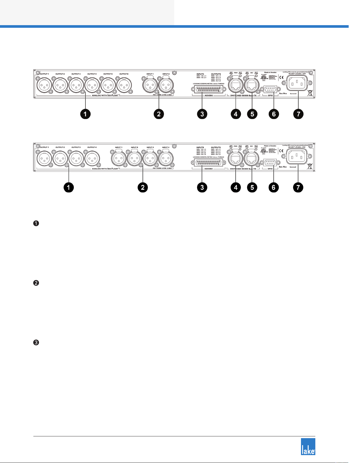
4.2 Back Panel Overview
Figure 4-2: LM 26 Back Panel Layout
Figure 4-3: LM 44 Back Panel Layout
Analog Outputs
Analog outputs are provided via standard XLR3M connections. The outputs are electronically balanced
and feature Lake Iso-Float circuitry; it is not recommended to use unbalanced connections. The output
impedance is 50 ohms, providing a maximum output level of +21 dBu. Please refer to section 7.1 for further
information.
Analog Inputs
Analog inputs are provided via standard XLR3F latching connectors. The inputs are electronically balanced
and feature Lake Iso-Float circuitry; it is not recommended to use unbalanced connections. The impedance
is 20 kohms (balanced), and the inputs can accept a maximum input level of +26 dBu. Please refer to section
7.1 for further information.
AES3 I/O
AES inputs and outputs are provided via a 25-pin DB25 connector. Inputs can be received on AES1 (Ch.1,2)
and AES2 (Ch.3,4) for all LM Series devices; the LM 44 also allows input from AES3 (Ch.5,6) and AES4
(Ch.7,8).
Outputs are via AES1 (Ch.1,2), AES2 (Ch.3,4), AES3 (Ch.5,6) and AES4 (Ch.7,8). Please refer to section 7.2
for further information.
8
Lake LM Series Operation Manual Rev 1.2.8
Page 15

Product Overview
The sample rates available for AES3 inputs and outputs are 44.1, 48, 88.2, 96, 176.4, 192 kHz; input and
output sample rates can be congured to lock to different sample rates.
Primary Network Connector
The primary Neutrik RJ45 etherCON
®
connection provides integration into an Ethernet control network
which may include other Lake Processors and the Lake Controller software. Network connection permits full
control of all functions along with real-time metering from a remote position. This device supports the Dante
audio networking protocol, which allows transmission of multichannel, high-denition digital audio over the
same Ethernet connection.
Use the primary connector when using a star network topology, consisting of individual Cat-5e connections
between the devices and an Ethernet switch. Alternatively this connection can be used to daisy chain
directly to another Lake Processor. The daisy chain topology should not be used with Dante.
For a technical reference of the Ethernet Port, please refer to section 7.3. Additional information is available
in the Lake Network Conguration Guide.
The Ethernet ports automatically switch to operate at Ethernet data
rates of 100 Mbps or 1000 Mbps, and allow straight or crossed
network cables. Two LEDs above each port indicate valid network
connection (LINK) and network activity (ACT).
Secondary Connector
The secondary network connector can be used to daisy-chain multiple LM & PLM Series and legacy Dolby
and Lake devices. Alternatively, a Dante dual-network topology can be created by connecting all secondary
network connectors to a separate Ethernet switch, ensuring full redundancy in the event of a network
component failure.
Additional processor conguration is required for a
dual redundant network setup. See the Lake
Controller Operation Manual for further details.
For a technical reference of the Ethernet Port, please refer to section 7.3. Additional information is available
in the Lake Network Conguration Guide.
When connecting multiple devices to an Ethernet
network, care must be taken NOT to create a
closed loop which causes network malfunction.
Lake LM Series Operation Manual Rev 1.2.8
9
Page 16

Product Overview
GPIO Connector
A 9-pin GPIO (General Purpose Input Output) connection is provided to enable integration with external
systems such as alarm/re systems, providing basic control of power state, mute along with fault notication to an external monitoring system. Please refer to sections 6.10.4.4 and 7.4 for further details.
Mains Power Connector
A universal power supply capable of accepting 70-265 V ~ 50-60 Hz : 25 W is built into LM Series devices.
The IEC power cable provided includes a locking feature via a pin on the bottom of the connector; the
connector can accept standard or locking IEC power cables.
The power supply must be connected to AC mains using a power cable with a correctly wired plug for the
country of operation.
10
Lake LM Series Operation Manual Rev 1.2.8
Page 17
Signal Flow and Lake Processing
5. Signal Flow and Lake Processing
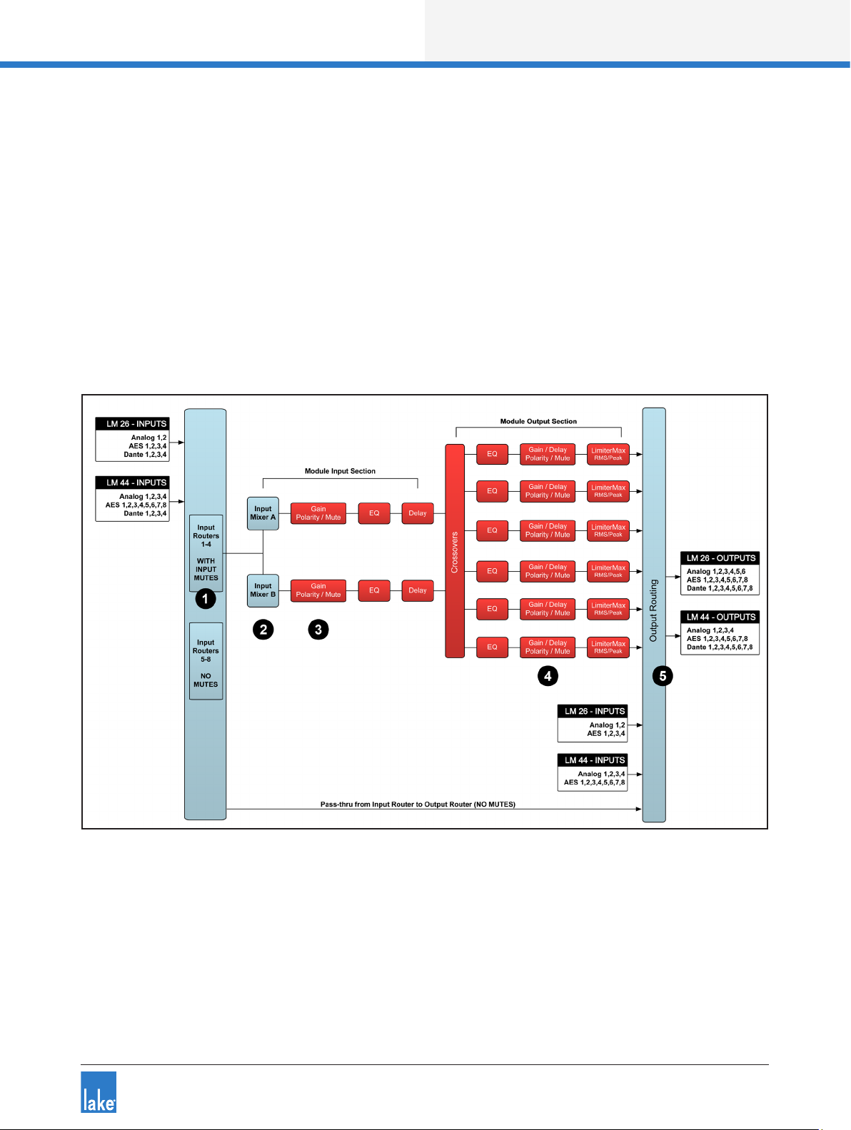
5.1 Signal Flow
The gures below depict the audio signal ow for LM Series devices congured in both Contour and Mesa
modes. It is worth noting that this sophisticated device provides up to ve points in the signal chain where
the signal level can be adjusted, muted or disconnected (depending on whether congured in Contour or
Mesa Mode as described below). The blue sections represent Frame data, and the red sections represent
Module data - please refer to the Lake Controller Operation Manual for further information.
Important information regarding correct setting of the gain structure can be found in section 9.1.
Figure 5-1: LM Series Signal Flow (Contour Mode)
Lake LM Series Operation Manual Rev 1.2.8
11
Page 18
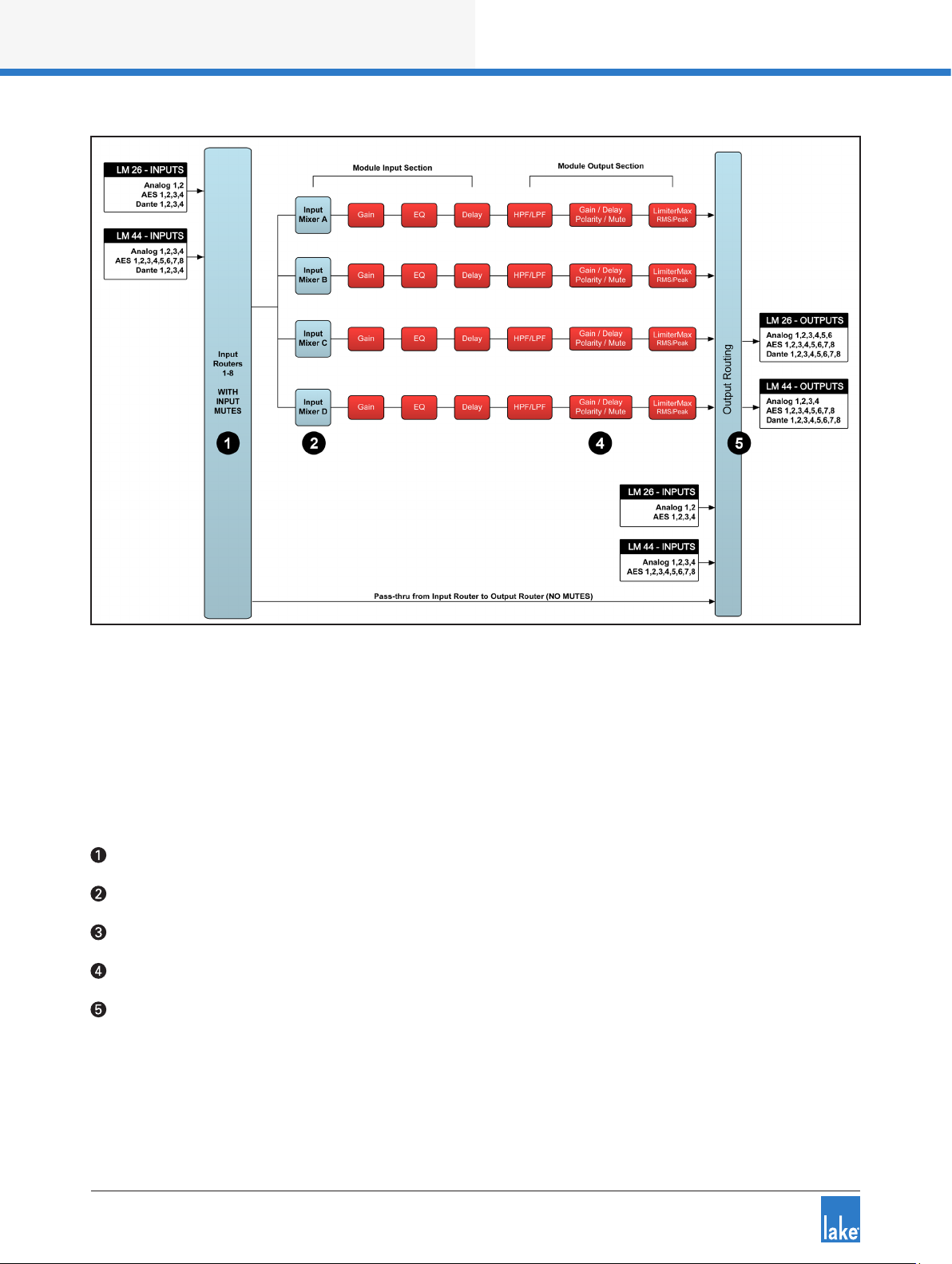
Signal Flow and Lake Processing
Figure 5-2: LM Series Signal Flow (Mesa Mode)
Please refer to section 6.10.4.2 for information on changing the Frame conguration between Contour and
Mesa Modes.
5.1.1 Level Adjustments & Mute Points
The numbers below correspond the points identied in Figure 5-1 and Figure 5-2.
Input Router Stage - Input selection and MUTE
Input Mixer Stage - Router ON/OFF connection to mixer and gain settings
Module Input Stage - Mute (N/A for LM Series Mesa Mode) and gain settings
Module Output Stage - Mute and gain settings
Output Router Stage - Output ON/OFF routing connections
In Contour Mode, a Module can be connected to Input Routers 1-4 providing all ve stages of mute/connectivity functionality via the front panel interface or the Lake Controller; Input Routers 5-8 allow stage 1 input
selection only (MUTE unavailable), along with stage 5 output ON/OFF routing connections (i.e. pass-thru).
12
Lake LM Series Operation Manual Rev 1.2.8
Page 19

Signal Flow and Lake Processing
In Mesa Mode, a Module can be connected to any of the eight input routers, providing four stages of mute/
connectivity (stage 1,2,4 & 5).
If the required audio signal is not passing correctly,
verify the connection, mute and gain settings at all
ve stages.
5.2 Lake Processing and Control
As outlined in section 2.2.1, this device integrates seamlessly into the Lake Processing environment,
providing all features, functionality and connectivity associated with all Lake Processors. The internal Lake
Processing includes programmable crossovers, EQ, dynamics and other functions, and can be fully controlled via the supplied Lake Controller software. Additionally, many functions can be controlled or accessed
directly via the front panel.
The Lake Controller Operation Manual and Lake Network Conguration Guide are supplied on the accompanying CD-ROM and additional documentation is available from the Start Menu after software installation.
Visit http://lakeprocessing.com to download the latest software, rmware and documentation for your
devices.
5.3 Modules and Frames
5.3.1 Overview
A Frame represents one physical Lake Processor (e.g. LM 26 or LM 44). In Contour Mode, a maximum
of two Modules are contained within each Frame; these are referred to as Module A and Module B. The
number of Modules shown in a given Frame is also dependent upon the signal processing conguration of
that Frame. In Mesa Mode each Frame contains four Modules labelled A, B, C & D.
In Contour Mode, each Module can be congured as a Classic Crossover (Bessel, Butterworth, LinkwitzRiley), as a Linear Phase Crossover, or as multiple full bandwidth Auxiliary Outputs. The default conguration
for the LM 26 is 2 x Classic 3-Way Modules, providing a total of six Module outputs. The default conguration for an LM 44 is four Mesa EQ Modules, providing a total of four Module outputs.
Please refer to the Lake Controller Operation Manual for further information.
5.3.2 Super Modules
Super Modules allow control of multiple Modules of the same type, distributed across multiple Frames, as
a single entity within the Lake Controller software. A change made in the Super Module is replicated across
all assigned Modules, resulting in improved efciency in system conguration and a reduction of on-screen
icons within the Lake Controller software.
Lake LM Series Operation Manual Rev 1.2.8
13
Page 20

Signal Flow and Lake Processing
The key benet of this feature is the ability to connect and control crossovers, levels and EQ across multiple
hardware devices simultaneously from the Lake Controller. For example, one device may be driving sub and
low-frequency speakers, while another device controls mid-range and hi-frequency drivers. Using a single
adjustment the crossover points between the two devices can be changed simultaneously.
Please refer to the Lake Controller Operation Manual for further information regarding Super Modules.
5.4 Loudspeaker Processor (Contour Mode) Overview
In Contour Mode, LM Series devices may be congured with up to two processing Modules containing
a total of up to six processing Module outputs as shown in Figure 5-1 on page 11. Each set of processing
elements is referred to as a Module and can be congured as crossovers, full-bandwidth auxiliary outputs,
or a combination of the two. The relationship between inputs and outputs is dened via the Lake Controller
or via the front panel I/O CONFIG Menu.
The Lake Processing system provides two distinct categories of crossovers:
▸ Innite Impulse Response lters (IIR) such as the classic Bessel, Butterworth or Linkwitz-Riley types;
these are available with slopes ranging from 6 dB/octave to 48 dB/octave.
▸ Finite Impulse Response lters (FIR) providing zero phase shift with steep transition slopes at the
crossover frequencies. These are also referred to as Linear Phase Crossovers.
Further details on these types of crossovers and information on conguring various module types can be
found in the Lake Controller Operation Manual.
5.5 System Equalizer (Mesa Mode) Overview
In Mesa Mode, an LM Series device provides four processing Modules with independant EQ, HPF/LPF,
Gain, Polarity, Delay and Limiters as shown in Figure 5-2 on page 12. The relationship between inputs and
outputs is dened via the Lake Controller or via the front panel I/O Input Cong Menu.
Please refer to the Lake Controller Operation Manual for addiitonal information on Mesa Mode and associated I/O routing.
5.6 Switching between Contour and Mesa Mode
When switching between Contour and Mesa Modes, all current Frame conguration data is lost (Presets
are retained) and the device is completely recongured into the selected Mode. Ensure you have stored any
existing frame conguration data before conguring into a different mode.
The device conguration may be changed either via the Front Panel MENU > FRAME > FRAME RST (refer
to section 6.10.4.2) or via the Lake Controller MODULES > I/O CONFIG > FRAME CONFIG menu (refer to
the Lake Controller Operation Manual).
14
Lake LM Series Operation Manual Rev 1.2.8
Page 21

Signal Flow and Lake Processing
5.7 Files and Presets
The Lake system provides various methods for storing and recalling Module, Frame, or system-wide data.
An overview is provided below; for further information please refer to the Lake Controller Operation Manual.
5.7.1 Module, System and Sub-System Conguration Files
Module, System and Sub-System Conguration les are stored on the Lake Controller PC, and data is
passed across the network when recalling or storing these type of les.
▸ A Module le is the smallest set of data that can be stored and recalled; it contains crossover, gain,
delay, and limiter information for an individual loudspeaker (i.e. the data shown in red in the signal ow
diagrams in section 5.1). A Module le may be recalled into other Lake devices. It is not possible to
store a Module File directly on the hardware device.
▸ A System or Sub-System Conguration File contains a set of Module le information in addition to
Frame related information such Group data and I/O conguration (i.e. the data shown in blue in the
signal ow diagrams in section 5.1).
5.7.2 Frame and System Presets
This device allows the complete processor conguration to be stored as a Frame Preset on the
hardware unit itself. Presets can be recalled via the front panel (please refer to section 6.10.6) or via the
Lake Controller software (please refer to the Lake Controller Operation Manual). Presets can be stored into
the device using the Lake Controller or the LM Series Preset Manager utility.
A maximum of 100 Frame Presets can be stored on this device. The data within a Frame Preset includes the
congurations of both Modules in the Frame, including all levels, crossover, EQ, input mixer, output routing,
and all other Module, Frame and Group parameters. As Frame Presets are stored in the device, complete
processor congurations may be recalled without the need to connect the device to a PC.
Using the System Presets function in the Lake Controller, entire system congurations can be stored and
recalled across a network of LM & PLM Series devices, Dolby Lake Processors, Mesa Quad EQ and the
Contour Pro 26. This enables fast retrieval and switching of entire system congurations as minimal data is
being sent between the Controller and Processors.
Lake LM Series Operation Manual Rev 1.2.8
15
Page 22

Front Panel Interface
6. Front Panel Interface
An overview of the front panel interface is provided in section 4.1. This chapter describes each cluster of
controls as shown in Figure 6-1.
Figure 6-1: Front Panel Interface
6.1 Overview
The front panel interface is framed by two sturdy cast aluminium handles . The majority of functions
on LM Series devices can be operated and monitored via the following controls and display features: On/
standby button , front-panel LCD display screen , function buttons , rotary encoder , a
dynamic illuminated I/O divider and the dedicated Module input output mute buttons and LED meters .
The front panel has two basic modes: Meter Mode and Menu Mode.
▸ Meter Mode provides the following views: Home View (default), Input Meters View (Mesa Mode only)
and I/O Status View. To navigate through these views, press the METER button. Please refer to section
6.9 for further information on Meter Mode.
▸ Menu Mode provides various menus for viewing and editing parameters and is selected by pressing the
MENU button. Select the required submenu by pressing the associated button. Please refer to section
6.10 for further information on Menu Mode.
6.1.1 Warning, Fault and Mute Indications
Fault or warning conditions are indicated via the LEDs embedded in the dynamic function buttons; a simultaneous description is shown adjacent to the button, on the LCD.
Further information on faults and warnings is provided in section 6.7.2 and section 8.1.
16
Lake LM Series Operation Manual Rev 1.2.8
Page 23
Front Panel Interface
6.1.2 Selecting a Module in the Lake Controller software via the device
It is sometimes useful to identify which Module icon/s in the Lake Controller software are associated with a
particular hardware Frame. To highlight the module in the Lake Controller software:
1. Ensure Meter Mode is selected
2. Press the button adjacent to the Module description on the LCD
If the Frame is online, but the Module is not in the work area, the selected Module will be centred on the
Module scroll bar (assuming the Modules Menu is selected in the Lake Controller).
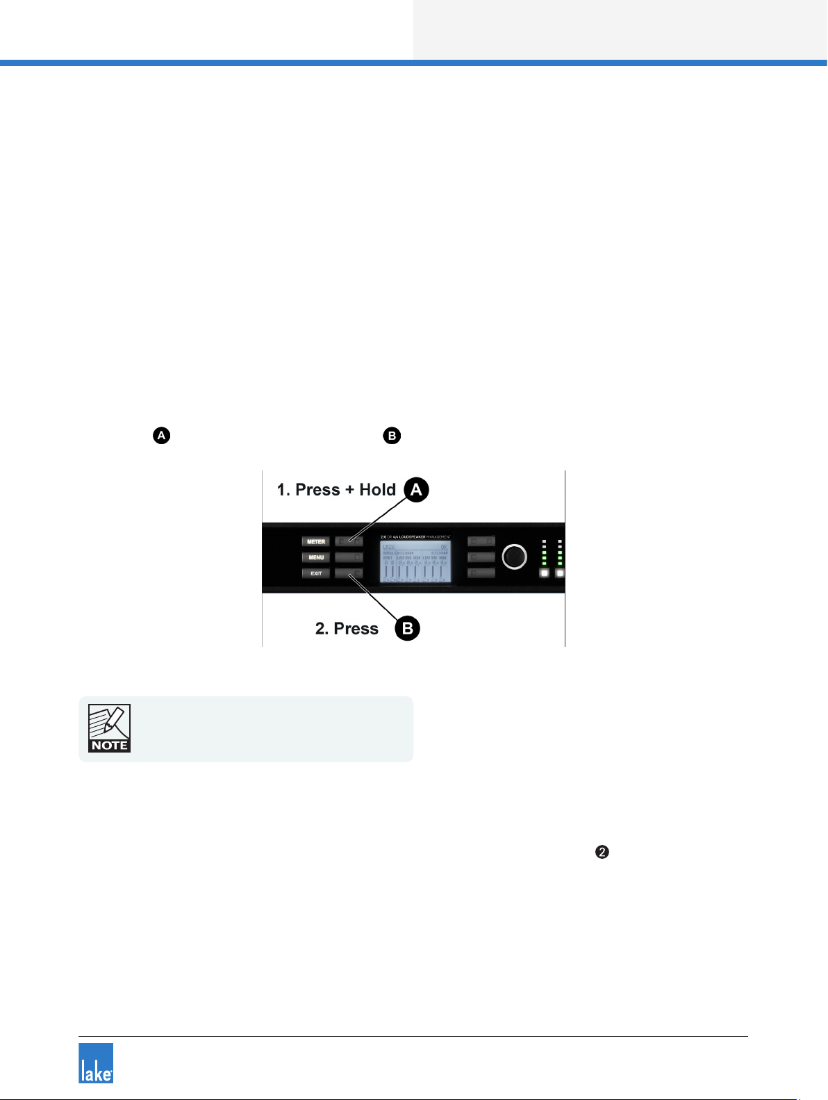
6.2 Front Panel Key Lock
It is possible to lock the front panel buttons for security purposes. When this function is active, all front
panel controls are disabled and all adjustment must be made via the network. To lock controls, press and
hold button then simultaneously press button as shown in Figure 6-2; repeat this process to unlock.
Figure 6-2: Locking / Unlocking Front Panel Controls
A key icon will appear at the top of the display
when the Front Panel is locked.
6.3 Power Button
The unit is powered on by pressing the left-most button on the front panel, labelled in Figure 6-1. It has
a bi-color power symbol which illuminates red when connected to the AC mains and the unit is in standby
mode. It turns green when the button is pressed to turn the processor on. A subsequent press of this
button returns the unit to standby mode.
Lake LM Series Operation Manual Rev 1.2.8
17
Page 24

Front Panel Interface
6.4 Meter Button
The front panel display has two main operating modes, Meter Mode (default) and Menu Mode. In normal
operation, the display will be in Meter Mode.
The following views are available in Meter Mode: Home View (default), Input View (Mesa Mode only) and
I/O Status View. Pressing the METER button
when in Menu Mode will return the system to Meter Mode, with the Home View displayed. Please refer to
section 6.9 for further information.
6.5 Menu Button
Menu Mode is selected by pressing the MENU button . The screen displays the top level menu with
various submenu options. Press the button adjacent to the required submenu to select it.
Pressing the MENU button while in Menu Mode will display the previous menu level.
scrolls through these views. Pressing the METER button
Menu Mode is used for processor conguration, or for editing a parameter. Please refer to section 6.10 for
further details.
6.6 Exit Button
In Menu Mode, pressing the EXIT button returns back one menu level. In Meter Mode, pressing EXIT
returns the display to the Home View.
6.7 Dynamic Buttons, Controls and LEDs
Figure 6-3: LCD with Dynamic Buttons, Controls and LEDs
18
Lake LM Series Operation Manual Rev 1.2.8
Page 25

Front Panel Interface
6.7.1 Communication LED
This bright white LED signies selection in the Lake Controller, or Controller communication providing visual
conrmation of:
1. Network communication between the Lake Controller and the Lake Processor (Flashing LED).
2. Selection of the Lake Processor in the Lake Controller software (Steady LED).
The Communication LED can be dimmed via the
front panel by selecting Frame menu, and then
Front - Dimming.
6.7.2 Faults and Warnings LED
This LED turns red to indicate a fault or mute state and turns yellow to indicate a warning. Additional clarication of the fault or warning is displayed in the LCD. All mute, fault and warning states displayed on the
front panel are summarized in section 8.1.
Additional faults and warnings are reported in the Event Log of the Lake Controller only. All faults and
warnings recorded in the Event Log are listed in section 8.1 along with scenarios that may have arisen to
cause them.
Device Fault / Mute Description LCD Warning Text Event Log Warning Text
LM 44 Only A/D PSU Fault PSU FAULT Frame Fault: PSU
All LM Series Protective Mute State PROTECTIVE MUTE Protective mute via GPIO
All LM Series Overtemperature OVERTEMP Temp Fault: DSP area
All LM Series No Input Source Available NO INPUT No Input Source
All LM Series Analog Input Fault ANALOG IN FAULT Frame Fault: Analog input
All LM Series Fan Alarm FAN FAULT Frame Fault: Fan error
All LM Series Input Router Mute INPUT RTR MUTE Input Router x mute
Table 6-1: Faults (RED FAULT / WARNING LED)
Lake LM Series Operation Manual Rev 1.2.8
19
Page 26

Front Panel Interface
Warning Description LCD Warning Text Event Log Warning Text
Digital Clock Slipping CLOCK SLIPPING AES/Dante input clock slipping
Temperature Warning TEMP WARNING Temp Warning: DSP area
Controller Ofine CTRL OFFLINE n/a
Module Input/Output mute status is indicated by
the dedicated mute button LEDs. Clipping is
indicated by the associated red meter segment.
Please refer to section 6.8 for further details.
6.7.3 Rotary Encoder
The rotary encoder is used to adjust parameters in conjunction with the selection made via the dynamic
function buttons and LCD menus. The ring around the rotary encoder illuminates when a selected parameter
is available for adjustment.
Table 6-2: Warnings (YELLOW FAULT / WARNING LED)
Turn the encoder clockwise to increase the selected parameter, or counter-clockwise to decrease the value.
Parameters with only two states (e.g. ON, OFF) are toggled by turning clockwise or counter-clockwise.
Some parameters enable simultaneous adjustment of a combination of input and output channels.
To select which channels are adjusted:
1. Press the associated soft button/s to select the parameter/s for editing.
A selected parameter is indicated by inverse text and background color.
2. Use the rotary encoder to change the value.
It is possible to select multiple parameters for simultaneous editing even if the values are different on each
channel. Turning the rotary encoder will adjust each parameter by the same increment. When in Meter
Mode, the rotary encoder allows the user to change between the available meter views.
Some menus permit parameters to be adjusted
across multiple channels simultaneously by default.
6.7.4 Dynamic Function Buttons
The buttons surrounding the display are unlabeled because their functions change according to the currently
selected menu or display.
20
Lake LM Series Operation Manual Rev 1.2.8
Page 27

Front Panel Interface
In Menu Mode these buttons are used to navigate the menu structure. A white LED illuminates on each
button when a valid menu option is available.
6.8 Module I/O Mute Buttons and LED Meters
LM Series devices provide mute functions at several points in the audio signal path. Please refer to section
5.1 for mute locations and descriptions.
Three types of mute are available from the front panel:
1. Input Router Mutes
2. Module Input Mutes
3. Module Output Mutes
In Home View (default), Module Input and Output Mutes are controlled via the dedicated mute buttons
underneath each channel’s ve-segment LED meter as shown in Figure 6- 4.
Figure 6-4: Dedicated Module Input and Output Mutes - Home View
In Figure 6-4, the buttons labelled A & B provide Module input muting; the buttons labelled 1-6 provide
Module output muting.
The embedded LED in each mute button conrms whether the associated Module input/s or output/s are
muted (red), unmuted (white), associated input router is muted (pink), or unused (not illuminated) as shown
in Figure 6-5.
A pink LED indicates a partial mute caused by a mute on an Input Router used by the associated Input
Mixer. If all Input Routers used by an Input Mixer are muted the LED turns red to indicate a full mute; this
type of mute cannot be unmuted from Home View. Input router mutes are accessed via the I/O Status View
as described below, or via the Lake Controller Levels screen as described in the Lake Controller Operation
Manual.
Lake LM Series Operation Manual Rev 1.2.8
21
Page 28

Front Panel Interface
In I/O Status View (accessed via the METER button as described in section 6.9.4) the front panel mute
buttons and meters change to show Input Router mutes and Input Router metering; the dynamic I/O divider
line is not present and the buttons and meters change to represent the input router mute status and associated metering.
The number of Input Routers varies depending on the whether the frame is congured as Contour or Mesa
as shown in Figure 6-6; the number and location of the Input Router channels is identied by the labels
R1-R8.
Figure 6-5: Mute Button LED Colours and States
Figure 6-6: I/O Status View - Input Router Mutes and Meters
The Input Router Mutes can also be viewed and changed via buttons adjacent to each label the front panel
I/O Status view.
6.8.1 Module Input and Output Mutes
In Home View, dedicated mute buttons are provided for the Module inputs and Module outputs. To mute
or unmute a module input or output, tap the corresponding button. The button illuminates as described in
section 6.8 and shown in Figure 6-5.
Module input mutes are only available in Contour Mode; Module input mutes are not applicable in Mesa
Mode. The quantity and position of the output mute buttons changes as shown in Figure 6-4 depending on
whether the device is congured in Contour Mode (six outputs) or Mesa Mode (four outputs).
Please refer to the Lake Controller Operation Manual for details of Module mute controls via the software.
22
Lake LM Series Operation Manual Rev 1.2.8
Page 29

Front Panel Interface
6.8.2 Clip Indication
The dedicated 5-segment metering LEDs (Figure 6-4 ) display Module input and output clip or pre-clip
conditions. Additionally, the faults and warnings LED described in section 6.7.2 provides clip warnings for
input mutes, or GPIO protective mutes, along with conrmation text on the LCD screen.
Clipping is monitored at the following positions in the signal chain:
▸ Analog Inputs: If the input signal exceeds either +12 dBu or +26 dBu (according to analog sensitivity
setting), a clip indication will be given. This does not apply if digital inputs are selected.
▸ Module Inputs: If the signal level at this point exceeds +25 dBu, a clip indication will be given.
▸ Module Outputs: If the signal level at this point exceeds +21 dBu, a clip indication will be given.
6.9 Meter Mode
6.9.1 Home View (Contour Mode)
The default view when powering on an LM Series device device congured in Contour Mode is the Meter
Mode > Home View as shown in Figure 6-7.
Figure 6-7: Meter Mode > Home View
Home View (Contour Mode) provides a summary of Module I/O gain level and limiter gain reduction, along
with frame, module and channel labeling information.
6.9.2 Home View (Mesa Mode)
The default view when powering on an LM Series device congured in Mesa Mode is Meter Mode > Home
View as shown in Figure 6-8.
Lake LM Series Operation Manual Rev 1.2.8
23
Page 30

Front Panel Interface
Home View (Mesa Mode) provides a summary of Module output gain level and limiter gain reduction, along
with frame, module and channel labeling information.
6.9.3 Input Meters (Mesa Mode)
Pressing the METER button from Home View in Mesa Mode will display the Input Meters View similar to
that shown in Figure 6-9. This view is not available in Contour Mode as Contour Mode Home View includes
both input and output metering information.
Figure 6-8: Meter Mode > Home View (Mesa - Module Outputs)
Figure 6-9: Meter Mode > Input Meters (Mesa Only)
6.9.4 I/O Status View
Pressing the METER button from Home View (once in Contour Mode, twice in Mesa Mode) results in the
I/O Status View being displayed, similar to that shown in Figure 6-10. There are two pages to this screen;
press the meter button again to display page two. Page one displays the selected input status and metering
information for input routers 1-4, page two displays input routers 5-8.
In I/O Status View, the front panel mute button and metering LED’s change to represent the Input Router
mute status an metering levels as described in 6.8.
24
Lake LM Series Operation Manual Rev 1.2.8
Page 31

Figure 6-10: Meter Mode > I/O Status View
This section displays the screen title (left) and frame fault or warning description (right)
This section displays conrmation of the following settings:
Dante Clock Master (no icon = Dante Slave or Dante Disabled)
AES3 Input Terminated (no icon = Unterminated)
Analog Inputs Iso-Float Grounded (no icon = Floating)
Analog Outputs Iso-Float Grounded (no icon = Floating)
Front Panel Interface
The main section of the I/O Status View displays status and metering information for four of the eight
input routers. The information displayed for each input includes the currently selected input source type,
input router gain level meter (displayed as a horizontal bar and numeric dB, and also shown on the main
front panel LED meters), input mute status, analog headroom, digital sample rate, digital clock selection and
digital clock locking status.
If an Input Router is muted, the top-right LED is illuminated red as shown in Figure 6-10, and the frame
fault text in section A of the screen will display INPUT MUTE. The fault and warning LED illuminates red or
yellow in all Meter and Menu Views as described in section 6.7.2 and section 8.1.
These buttons allow muting/unmuting of the associated device input router. Conrmation of each input
router’s mute status is displayed on the LCD next to the associated button as shown for input 2 in Figure
6-10. To view inputs 5- 8 (I/O Status 2) press the METER button, or turn the rotary encoder clockwise.
The faults and warnings LED is accompanied by text on the top-right side of the LCD. The LED illuminates red if any input is muted, or if another fault condition occurs; it illuminates yellow if a warning condition
arises. Please refer to section 6.7.2 for further details.
6.10 Menu Mode
6.10.1 Overview
The majority of functions can be accessed via Menu Mode on the front panel. These functions include
the adjustment of gain, delay, limiters, input and output routing, and the ability to recall Frame Presets.
Menu Mode can be accessed at any time by pressing the MENU button.
Lake LM Series Operation Manual Rev 1.2.8
25
Page 32

Front Panel Interface
After pressing the MENU button, various submenu options are displayed as shown in Figure 6-11
Figure 6-11: Menu Mode > Main Menu
Press the illuminated button adjacent to the required option to display an associated submenu. When
parameter level is reached, individual parameters may be selected for adjustment by pressing the adjacent
button. The selected parameter value/s are highlighted, and are adjustable using the rotary encoder.
A parameter may be adjusted simultaneously across multiple channels by selecting all values to be adjusted;
any current value offsets are retained. Some parameters default to multiple selection, with all inputs or
outputs adjusted simultaneously. Changes are effected in real-time and a stored without further conrmation. Pressing EXIT returns to the previous menu level, automatically retaining any parameter changes.
.
All parameters are also editable via the Lake
Controller unless specied otherwise.
6.10.1.1 Parameters with Individual Values and Group Totals
The following parameters display two values:
▸ MODULE > GAIN
▸ MODULE > DELAY
▸ MODULE > LIMITERS > MA XRMS LEVEL
▸ MODULE > LIMITERS > MA XPEAK LEVEL
The Module parameter can be adjusted using the rotary encoder. The Group total (shown in brackets) is only
adjustable using the Groups function in the Lake Controller.
The Group total is the sum of the individual Module value plus any values for this parameter on all Groups to
which the Module is assigned. Please refer to the Lake Controller Operation Manual for further information
on Groups.
26
Lake LM Series Operation Manual Rev 1.2.8
Page 33

Front Panel Interface
6.10.1.2 Menu Structure Overview
From the Main Menu, the following submenus are available, as shown in Figure 6-11 and described in the
following sections.
▸ MODULE (See section 6.10.2)
▸ Mixer Gain
▸ Gain
▸ Delay
▸ Polarity
▸ Limiters
▸ INPUT CONFIGURATION (See section 6.10.3)
▸ Input Router
▸ AES Termination
▸ Iso-Float
▸ Output Router
▸ FRAME (See section 6.10.4)
▸ Frame Information
▸ Frame Reset
▸ Latency Match
▸ GPIO Conguration
▸ Front Panel
▸ FRAME PRESETS (See section 6.10.6)
▸ Preset Recall
For simplicity, the following sections refer to the
buttons by their associated name on the LCD
screen. E.g. ‘Press GAIN’ equates to ‘Press the
button adjacent to the Gain label on the LCD’.
6.10.2 Module Submenu
MENU > MODULE
After selecting the Module Menu, the screen shown in Figure 6-12 is displayed. Press the illuminated button
adjacent to the required option to view or edit the associated parameters.
Lake LM Series Operation Manual Rev 1.2.8
27
Page 34

Front Panel Interface
6.10.2.1 Mixer Gain
MENU > MODULE > MIXER GAIN
Figure 6-12: Module Submenu
Figure 6-13: Module Input Mixer Gain Edit Screen
The top left button labeled PAGE toggles between the input mixer gain settings for each Module in the
Frame. Press any other illuminated button to select a parameter for editing then use the rotary encoder to
make adjustments. Multiple parameters may be selected and adjusted together.
6.10.2.2 Gain
MENU > MODULE > GAIN
For frames where both Modules have four output channels or less, a detailed parameter screen as shown
in Figure 6-14 is displayed. Where Module A has ve output channels or more, the combined summary edit
screen shown in Figure 6-15 is the only screen available.
28
Lake LM Series Operation Manual Rev 1.2.8
Page 35

Front Panel Interface
Figure 6-14: Single Module Gain Edit Screen
Pressing the top left PAGE button scrolls between the following three views for modules with four output
channels or less:
1. Module A Input and Output Gain Settings (with Group totals)
2. Module B Input and Output Gain Settings (with Group totals)
3. Module A & B Combined Summary (without Group totals)
Pressing any other illuminated button on any of these three screens allows direct editing of the Module
parameter using the rotary encoder.
Figure 6-15: Module A+B Combined Gain Summary Edit Screen
On the combined module summary screen, use the NAV button to navigate through the channels, and the
SEL button to select a parameter for editing. Selected parameters are highlighted using inverse video on the
value. The navigation cursor is identied by a bounding box around the abbreviated channel label. Multiple
gain values may be adjusted in 0.1 dB increments subject to dened level limits.
6.10.2.3 Delay
MENU > MODULE > DELAY
Module Delay adjustment follows the same logic as Module Gain. Please refer to section 6.10.2.2 for further
information. Multiple delay values may be adjusted simultaneously in 0.1 ms increments, subject to dened
level limits.
Lake LM Series Operation Manual Rev 1.2.8
29
Page 36

Front Panel Interface
The audio signal may be delayed (typically for reasons of driver or delay subsystem alignment) at either
the Module inputs or on individual outputs. Delay added at the inputs affects all outputs equally, and will
be generally be introduced to time-align arrays of loudspeakers at different locations. Delaying individual
outputs may be desirable to time-align drivers in the same cabinet or array.
6.10.2.4 Phase (Polarity)
MENU > MODULE > PHASE
Module Phase adjustment follows the same logic as Module Gain. Please refer to the section 6.10.2.2 for
further information. Phase may be changed on one input or output at a time.
Audio phase reversal is available at the inputs to Module A and Module B, and also individually on the
six output channels. The LCD displays ‘Positive’ for normal operation, and ‘Negative’ when the phase is
inverted.
6.10.2.5 Limiters
MENU > MODULE > LIMITERS
LimiterMax parameters can be adjusted via this submenu. By default, simultaneous adjustment of most
limiter parameters across all output channels is selected, although channels may be adjusted individually if
required. Attack and Release times must be adjusted individually per channel.
MaxPeak Level (MaxPeakLvl)
This sets the maximum peak signal level at the Module outputs. It is adjustable from -30 dBu to +30 dBu
in 0.1 dB increments, subject to user-dened level limits. The Group total is displayed (in brackets) for each
channel.
MaxRMS Level (MaxRMSLvl)
This sets the maximum RMS signal level at the Module outputs. It is adjustable from -30 dBu to +30 dBu
in 0.1 dB increments, subject to user-dened level limits. The Group total is displayed (in brackets) for each
channel.
MaxRMS Corner (MaxRMSCor)
A soft-knee or hard-knee corner may be applied to the RMS Limiter. A soft-knee corner gently increases
limiting as the signal approaches the threshold; a hard-knee corner applies full limiting to any signal exceeding the threshold by any amount, but none to signals below the threshold.
30
Lake LM Series Operation Manual Rev 1.2.8
Page 37

Front Panel Interface
The Corner parameter is adjustable in 0.1 dB increments, subject to dened level limits. This gure represents the level below the limiter threshold at which compression commences; the larger this negative value,
the softer the knee. A setting of 0 dB implies a hard-knee characteristic.
LimiterMax provides peak and RMS limiting
features, referred to as MaxPeak and MaxRMS
respectively. Full details regarding LimiterMax can
be found in the Lake Controller Operation Manual.
6.10.3 I/O Cong Submenu
MENU > I/O CONFIG
Figure 6-16: I/O Cong Submenu
This menu provides conguration options for input and output routing, along with settings for AES Termination and Iso-Float as described in the following sections.
6.10.3.1 Input Router
MENU > I/O CONFIG > INPUT RTR
Figure 6-17: Input Router 1
The signal ow diagrams in chapter 5 highlight that there are eight Input Routers available on LM Series
devices.
Lake LM Series Operation Manual Rev 1.2.8
31
Page 38

Front Panel Interface
In Contour Mode, the signal from the rst four Input Routers can be routed to the Module Input Mixers;
in Mesa Mode, the signal from all eight Input Routers can be routed to the Module Input Mixers. In both
conguration modes, the signal from all eight Input Routers can be passed directly to any output.
Each router has four priority levels allowing any input to be placed in a sequence providing automatic input
signal fail over. AES3 and Dante inputs have priority over analog inputs.
Only one analog input is allowed in each router, and
the analog input must be at the lowest priority level
in relation to any other inputs.
Two modes of input selection are available, Auto Select and Forced Selection. The selected setting is also
visible from the I/O STATUS screen on the front panel, and via the Lake Controller.
In Auto Select mode, Priority 1 is checked for a valid input signal; if no signal is found, Priority 2 is checked,
and so on until a valid signal is located; this process occurs if the currently selected input fails. In Forced
Selection mode, one of the four priorities is xed regardless of whether a valid signal is present.
With a router selected on the front panel, press the middle button on the left of the LCD to activate this
parameter for editing; the text will be highlighted as shown in Figure 6-17. Use the illuminated rotary encoder
to scroll through the following options:
▸ Auto Select (default)
▸ Force Priority 1
▸ Force Priority 2
▸ Force Priority 3
▸ Force Priority 4
Assignment of Input Priority
Factory default settings assign AES3 to Priority 1 and Analog to Priority 4, with Priority 2 and 3 empty.
To change these settings via the front panel, select Priority slot number to be changed and use the rotary
encoder to scroll through the available options. Due to the signal hierarchy it is not possible to assign an
analog source to a higher priority than a digital source. Dante inputs are not selectable from the front panel;
their assignment must be made via the Lake Controller software.
Analog Input Sensitivity and Digital Gain Offset
While viewing the Input Router screen as shown in Figure 6-17, press PAGE to reveal existing input sensitivity for analog inputs, or digital gain offset for digital inputs. This is equivalent to the DISPLAY DETAILS
option in the Lake Controller. Adjust a parameter by pressing the associated button, and then use the rotary
encoder to change the value.
32
Lake LM Series Operation Manual Rev 1.2.8
Page 39

Front Panel Interface
The maximum input level accepted by the analog input pre-ampliers without clipping may be set to 12 dBu
or 26 dBu. Digital gain offset may be applied to AES3 digital input signals in 0.1 dB increments from -100 dB
to +15 dB.
6.10.3.2 AES3 Input Termination
MENU > I/O CONFIG > AES TERM
Figure 6-18: AES Termination Edit Screen
To adjust the AES3 Input Termination, select AES TERM from the I/O CONFIG menu then use the rotary
encoder to toggle the value. A setting of ‘Terminated’ is also displayed on the I/O STATUS screen.
For fault-free operation when using AES3 digital audio as an input source, inputs must be correctly terminated with the characteristic impedance of 110 ohm. The Input Termination setting is determined by the
method used to distribute the AES3 signals.
The processor at the end of a distribution line should be set to TERMINATED; all other processors should
be set to UNTERMINATED. If an AES3 distribution amplier (DA) is being used to distribute the digital audio
signals, with one DA output per processor, then all terminations should be on. However, if the AES3 is
daisy-chained, only terminate the last processor in the chain.
6.10.3.3 Iso-Float
MENU > I/O CONFIG > ISO-FLOAT
Figure 6-19: Iso-Float Menu
Lake LM Series Operation Manual Rev 1.2.8
33
Page 40

Front Panel Interface
To change the Iso-Float setting, press the Inputs or Outputs button, then adjust the value using the rotary
encoder. The current settings are also displayed on the front panel I/O STATUS screen.
The analog inputs utilize Iso-Float transformerless electronic balancing circuitry. This provides electrical isolation from an analog source comparable to that achieved with transformer-based designs. However, pin 1 of
the XLR input connector may be connected to ground within the device if desired. This option is selected by
using the rotary encoder to toggle between FLOATING and GROUNDED.
It may be necessary to change this setting to resolve ground loop problems when using analog inputs.
6.10.3.4 Output Router
MENU > I/O CONFIG > OUTPUT RTR
Figure 6-20: Output Router Conguration Screen
The LM Series device provides comprehensive output routing via the front panel interface. The number of
channels available for the audio source and destination varies depending on whether the device has been
congured in Contour or Mesa mode.
Figure 6-20 shows the functions available along with numbers to identify the various features described
below.
Press this button to toggle through the available audio sources
Press this button to move the cursor upwards
Press this button to move the cursor downwards
This section of the screen displays the selected audio source
This section of the screen displays the selected output destination type
This section of the screen displays the channels for the selected audio source
34
Lake LM Series Operation Manual Rev 1.2.8
Page 41

Front Panel Interface
This section of the screen displays the output routing conguration
Press this button to scroll through the available output destination types
Press this button to move the cursor to the left
Press this button to move the cursor to the right
Use the rotary encoder to toggle the selected routing point ON or OFF
Use the above function keys to navigate to the required audio source and output destination, then move the
cursor to a routing point and adjust using the rotary encoder.
▸ ‘X’ identies a connected routing point
▸ ‘O’ identies a currently unused and available routing point
▸ ‘-’ identies that routing is unavailable for this routing point, normally because another audio channel is
already routed to the output.
All three states are shown in inverse video when they are selected by the cursor.
6.10.4 Frame Submenu
MENU > FRAME
Figure 6-21: Frame Menu
The Frame Menu provides information and options relating to the device as a physical unit. It is referred to
as a Frame for consistency with Lake Controller terminology.
6.10.4.1 Frame Info
MENU > FRAME > FRAME INFO
Frame Info provides information about the device settings and conguration. All data in this front panel
menu is read-only; some parameters are xed, some can be changed only via the Lake Controller software.
Lake LM Series Operation Manual Rev 1.2.8
35
Page 42

Front Panel Interface
Frame Label
The Frame Label as dened in the Lake Controller is displayed in this menu. It is also displayed at the
top-left of the screen in Meter Mode, Home View.
Serial Number (Serial No.)
The printed serial number on the back panel of the device is also electronically embedded in the hardware,
and therefore cannot be removed or altered if stolen.
Network
Pressing the NETWORK button displays a further screen containing network conguration information.
All parameters are view-only on the front panel and are either not editable, or can only be adjusted via the
Lake Controller.
A summary at the top right of the screen conrms whether a valid connection is present for both Ethernet
ports, and whether the Lake Controller is online.
▸ IP Addr: Displays the Internet Protocol address for the selected unit and can only be changed via the
Lake Controller software. Please refer to the Lake Controller Operation Manual for further details.
▸ IP Mask: Displays the IP address subnet mask for the selected unit and can only be changed via the
Lake Controller software. Please refer to the Lake Controller Operation Manual for further details.
▸ MAC: Displays the unique Media Access Control Ethernet address for the processor. This value cannot
be changed.
▸ F.ID: Displays the Frame ID, a unique Lake product identier that cannot be changed.
6.10.4.2 Frame Reset and Conguration
MENU > FRAME > FRAME RST
Use this option to display a further menu with options to reset all parameters back to their original factory
default values, or to recongure the Frame in a different mode (i.e. Contour or Mesa). See section 8.3 for a
full list of the default factory reset parameter values.
Three types of reset are provided: Factory Reset, Contour Reset and Mesa Reset.
Factory Reset
A Factory Reset will reset all settings and parameters to the original factory-dened default values. This
includes the deletion of any Frame Presets stored within the device, and the relevant Frame conguration
for the device (LM 26 = Contour; LM 44 = Mesa). It also resets the IP Address and all network related
settings; a hard power cycle is required to complete this reset.
36
Lake LM Series Operation Manual Rev 1.2.8
Page 43

Front Panel Interface
Contour Reset
A Contour Reset will congure the Frame in Contour Loudspeaker Processor Mode (2-in, 6-out) and will
reset all settings and parameters to the original factory-dened default values for that conguration. Frame
Preset information and IP / Network conguration will be unaffected. A power cycle is not required to
complete this type of reset.
Mesa Reset
A Mesa Reset will congure the Frame in Mesa System Processor Mode (4-in, 4-out) and will reset all
settings and parameters to the original factory-dened default values for that conguration. Frame Preset
information and IP / Network conguration will be unaffected. A power cycle is not required to complete this
type of reset.
6.10.4.3 Latency Match
To turn Latency Match on or off, select the parameter using the adjacent button then change the status
using the rotary encoder.
When Latency Match is ON the LM Series device adds delay to match the overall processing delay of legacy
Lake Contour Pro 26 and Mesa Quad EQ products. Please refer to the Lake Controller Operation Manual for
further information.
6.10.4.4 GPIO
MENU > FRAME > GPIO
Figure 6-22: GPIO Menu
Four general purpose input/output conguration settings are available; two conguration options for inputs,
and two for outputs.
GPI Conguration
To adjust GPI 1 or GPI 2, press the associated button to display a screen similar to that shown in Figure
6-23.
Lake LM Series Operation Manual Rev 1.2.8
37
Page 44

Front Panel Interface
Table 6-3 lists the options available for General Purpose Input (GPI). These options can be set independently
for a transition from closed > open and from open > closed.
Figure 6-23: GPI Conguration
Acting on Transition Option
1. No Action
Protective Mute State
Standby State
Preset Recall
2. Toggle State
3. Mute
4. Unmute
1. No Action
2. Toggle State
3. Standby
4. Turn On
1. No Action
2. Recall #99
3. Recall #100
No Action -
Table 6-3: GPI Options
A change to the ‘Acting on’ setting takes effect the next time the transition occurs. For example, changing a
GPI closed to open transition when the selected GPI is currently open is not executed until the next transition to open.
A change in GPI open/closed state occurring when
the device is disconnected from power will be
acknowledged and executed when power is
reconnected.
GPO Conguration
To adjust GPO 1 or GPO 2, press the associated button to display a screen similar to that shown in Figure
6-24
38
Lake LM Series Operation Manual Rev 1.2.8
Page 45

Figure 6-24: GPO Conguration
Table 6-4 lists the options available for General Purpose Output (GPO).
Acting on State when Closed
Protective Mute State
Standby State
Fault
Ready
1. Muted
2. Unmuted
1. Standby
2. On
1. No Fault
2. Any Fault
1. Ready
2. Not Ready
Front Panel Interface
No Indication -
Table 6-4: GPO Options
Factory Reset and Soft Reset clear the protective
mute state.
Two input options (GPI) and two output options (GPO) may be set at any one time. The default GPIO
conguration is shown in Table 6-5. The current state (open/closed) is reported for all GPIO settings on the
front panel and in the Lake Controller software.
GPIO # Default Option
GPI 1 No Action
GPI 2 No Action
GPO 1 Standby State
GPO 2 Fault
Table 6-5: Default GPIO Conguration
Lake LM Series Operation Manual Rev 1.2.8
39
Page 46

Front Panel Interface
6.10.5 Front Panel Display Controls
MENU > FRAME > FRONT
Contrast
To adjust the front panel LCD contrast, select this option then use the rotary encoder to change the value.
Figure 6-25: Front Panel Display Controls Menu
Dimming
To adjust the front panel LCD & LED brightness, select this option then use the rotary encoder to change
the value.
6.10.6 Frame Preset Menu
MENU > FRAME PRST
Figure 6-26: Frame Preset Menu
To recall an existing Frame Preset, use the rotary encoder to select the required Preset then press the
RECALL button to overwrite the current conguration.
Frame Presets must initially be created in the Lake
Controller, and stored as a Preset using the Lake
Controller or the LM Series Preset Manager.
40
Lake LM Series Operation Manual Rev 1.2.8
Page 47

Front Panel Interface
Up to 100 Frame Presets can be stored in the device. The data within a Frame Preset includes the conguration of all Modules in the Frame including levels, crossovers, EQ, input mixer, and output routing.
As Frame Presets are stored within the device, complete processor congurations can be recalled without
connecting the device to a PC.
Lake LM Series Operation Manual Rev 1.2.8
41
Page 48

Back Panel Interface
7. Back Panel Interface
An overview of the back panel interface is provided in section 4.2. This chapter describes each cluster of
connections as shown in Figure 7-1.
Figure 7-1: Back Panel Interface (LM 26)
Figure 7-2: Back Panel Interface (LM 44)
7.1 Analog Inputs and Outputs
7.1.1 Analog Output XLR Connections
Six (LM 26) or four (LM 44) electronically-balanced analog outputs are provided via standard XLR3M connections.
OUTPUT 1 OUTPUT 2 OUTPUT 3 OUTPUT 4 OUTPUT 5 OUTPUT 6
Figure 7-3: Analog Output XLR Connections (LM 26)
42
Lake LM Series Operation Manual Rev 1.2.8
Page 49
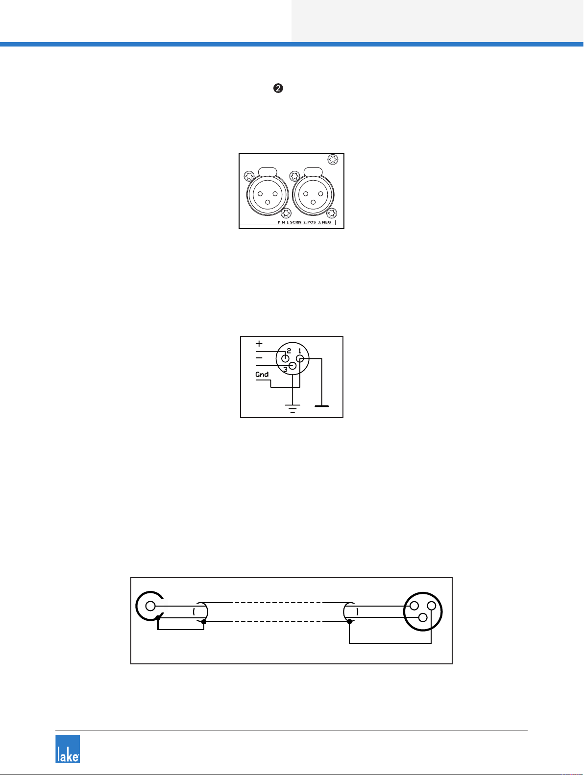
Back Panel Interface
7.1.2 Analog Input XLR Connections
Two (LM 26) or four (LM 44) electronically-balanced analog inputs are provided via latching XLR3F connections.
INPUT 1
INPUT 2
Figure 7-4: Analog Input XLR Connections (LM 26)
7.1.3 Analog XLR Wiring and Pin Out
All XLR connections are wired to IEC268 as shown in Figure 7-5.
Figure 7-5: IEC268 XLR Wiring and Pin Out
Pin 1: Ground / Shield
Pin 2: Hot (+)
Pin 3: Cold (-)
7.1.4 Unbalanced Operation
Balanced connections are recommended where possible. However, if it is necessary to drive the device
from equipment with an unbalanced output, wire the inputs as shown in Figure 7-6.
12
HOT
COLD
SCRN
Unbalanced Output
(Typically phono)
Figure 7-6: Balanced to Unbalanced Analog Wiring and Pin Out
HOT
COLD
SCRN
Balanced Input
(XLR)
3
Lake LM Series Operation Manual Rev 1.2.8
43
Page 50

Back Panel Interface
The method shown in Figure 7-6 uses twin-and-screen (balanced) cable and standard XLR pin connections
at the LM Series device end, with the cold wire and the cable screen connected to the signal ground of the
equipment at the source end.
This usually provides better noise and hum rejection than the more common method of joining pins 1 and
3 together in the XLR. However, if only a single-core (unbalanced) cable is available, the method shown in
Figure 7-7 may be used.
Unbalanced Output
(Typically phono)
HOT
SCRN
Balanced Input
(XLR)
Figure 7-7: Unbalanced Analog Wiring and Pin Out
12
HOT
SCRN
3
7.1.5 Iso-Float Electronic Balancing
The analog input and output electronic balancing circuits use the Lake Iso-Float system.
The Iso-Float technology combines the benets of transformer-coupled isolation with the advantages of
clean, direct-coupled inputs and outputs. The audio converters are galvanically isolated, and not connected
to the main ground. High-quality transformers and opto-isolators create a barrier between the device and
possible grounding aberrations from the outside electrical environment.
Iso-Float settings are adjustable via the front panel menu or the Lake Controller software.
7.2 AES3 Digital I/O
7.2.1 AES3 DB25 Connector
A DB25 connector following the Yamaha pin-out standard is provided for AES3 connectivity on the LM
Series device.
Figure 7-8: AES3 DB25 Connector and Pinout Reference
44
Lake LM Series Operation Manual Rev 1.2.8
Page 51

Back Panel Interface
This single DB25 connection provides four channels of AES3 input and eight channels of AES3 output as
shown in Figure 7-5 on page 43 below. A detailed wiring reference is provided in Figure 7-9.
AES3 Inputs AES3 Outputs
AES1: Ch. 1 & 2 AES1: Ch. 1 & 2
AES2: Ch. 3 & 4 AES2: Ch. 3 & 4
AES3: Ch. 5 & 6* AES3: Ch. 5 & 6
AES4: Ch. 7 & 8* AES4: Ch. 7 & 8
*LM 44 Only
Table 7-1: DB25 Input and Outputs
Figure 7-9 below provides a wiring reference for the DB25 connector.
Ch. Ground Hot Cold
1/2 IN 10 1 14
3/4 IN 10 2 15
5/6 IN 12 3 16
7/8 IN 13 4 17
1/2 OUT 22 5 18
3/4 OUT 23 6 19
5/6 OUT 24 7 20
7/8 OUT 25 8 21
Figure 7-9: DB25 Wiring Reference
Figure 7-5 on page 43 shows the only possible method of wiring; there is no equivalent of an unbalanced
connection in the digital domain.
7.3 RJ45 etherCON Network Connections
Two RJ45 etherCON style network connections are provided as shown in Figure 7-10.
Lake LM Series Operation Manual Rev 1.2.8
45
Page 52

Back Panel Interface
The switched 100/100 Base-T network connections auto-sense whether standard or crossover Cat-5e
cables are in use. The green ACT LED illuminates (ashes) to show network activity, and when a 100 Mbps
connection is present; the orange LED illuminates (static) to indicate a 1000 Mbps connection.
Pre-made cables with moulded RJ45 plugs are recommended. If it is necessary to make up custom Cat-5e
network cables, use pinout described in Table 7-2.
Figure 7-10: etherCON Network Connectors
Pin No. Color
1 Brown
2 Brown + White
3 Green
4 Blue + White
5 Blue
6 Green + White
7 Orange
8 Orange + White
Table 7-2: RJ45 Wiring & Pin Out Description
Figure 7-11: RJ45 Wiring and Pin Out Diagram
When the device is connected to an active network, the yellow LINK LED illuminates above the connector in
use. Data activity on the network is indicated by illumination of the green ACT LED. It is normal for the ACT
LED to icker either sporadically or continuously.
46
Lake LM Series Operation Manual Rev 1.2.8
Page 53
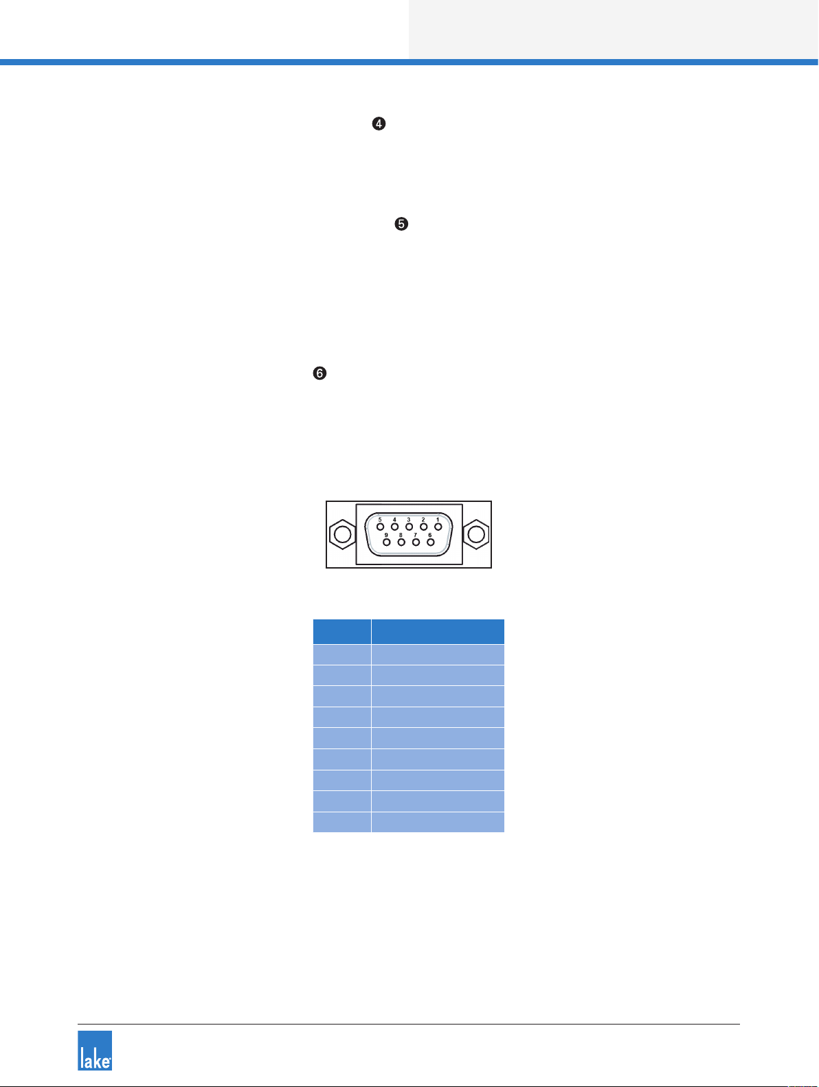
Back Panel Interface
7.3.1 Primary Network Connection
The Primary Network connection is used for Lake Controller connectivity and Dante digital audio. Please
refer to section 4.2 for additional information.
7.3.2 Secondary Network Connection
The Secondary Network connection may be used for a redundant Dante digital audio network. Please refer
to section 4.2 for additional information.
7.4 GPIO Connection
7.4.1 9-Pin GPIO Connector
A General Purpose Input/Output (GPIO) connection is provided, allowing interface to external devices such
as re alarm systems for emergency muting, processor power control, or preset recall. The GPO function
allows fault and state monitoring via external systems. Figure 7-12 in conjunction with Table 7-3 describes
the pinout conguration for the GPIO connector.
Figure 7-12: 9-Pin GPIO Connector and Pinout Reference
Pin No. Description
1 GPI 1a
2 GPI 1b
3 GPI 2a
4 GPI 2b
5 Chassis Ground
6 GPO 1a
7 GPO 1b
8 GPO 2a
9 GPO 2b
Table 7-3: GPIO Pinout Wiring Reference
GPIO conguration is available via the front panel interface or via the Lake Controller software. Please refer
to section 6.10.4.4 of this manual for additional information on adjustment via the front panel, and refer to
the Lake Controller Operation Manual for information on adjusting via software interface.
Lake LM Series Operation Manual Rev 1.2.8
47
Page 54

Back Panel Interface
7.5 Universal Power Supply Connection
7.5.1 IEC Power Connector
A universal power supply capable of accepting 70-265 V ~ 50-60 Hz : 25 W is built into the device. The IEC
power cable provided includes a locking feature via a pin on the bottom of the connector; the connector can
accept standard or locking IEC power cables.
The power supply must be connected to AC mains using an IEC power cable with a correctly wired and
molded plug for the country of operation.
48
Lake LM Series Operation Manual Rev 1.2.8
Page 55

Appendix
8. Appendix
8.1 Faults and Warnings Overview
Fault or warning conditions are indicated by the LED shown in Figure 6-3 on page 18. As the LED indicates
several types of faults or warnings, a brief textual description of the fault or warning is provided on the LCD
display. Section on page 21 details the fault and warning indications that appear on the front panel. Table 8-1
lists the events that may have triggered each fault or warning condition.
LCD Text Event Log Text Type Description / Troubleshooting
ANALOG IN
FAULT
CLOCK
SLIPPING
CTRL OFFLINE - Warning
FAN FAULT
IN RTR MUTE
NO INPUT No Input Source Fault
OVERTEMP
PROTECTIVE
MUTE
PSU FAULT
TEMP
WARNING
- Frame Ofine Warning
-
-
Frame Fault:
Analog Input
AES Clock
Slipping
Frame Fault: Fan
error
Input Router X
Mute
Temp Fault: DSP
area
Protective mute
via GPIO
Frame Fault:
PSU
Temp Warning:
DSP area
Module Input
Mute
Module Output
Mute
Sound Source
Changed
Fault
Warning
Fault
Mute
Fault
Event
Fault
Warning
Mute
Mute
Warning
There is a problem with the analog input. Verify signal and connections.
The selected digital clock and digital input combination is not
aligned. Verify digital input conguration to ensure all clock settings
match.
The device is no longer able to communicate with the Lake Controller. Check network connectivity.
There is a problem with the fan on the device. To avoid overheating,
identify and x the problem immediately.
An input router is muted; all Modules and outputs sourced from
this input router will be affected.
No input signal can be identied for any valid unmuted input router.
Connect an input source, or verify input signals and connections.
The temperature has reached a critical 70
off or take steps to cool the unit immediately; continued operation
cannot be guaranteed.
A processor mute state has been triggered via GPIO. Change this
setting using the external control device.
There is a problem with the power supply for the Analog inputs.
Analog inputs will not be available. Send the device for service.
The temperature has reached 55
ture and take additional steps to reduce temperature if it continues
to increase.
The Lake Controller is no longer able to communicate with the
device. Check network connectivity.
A Module Input has been muted. The mute is identied via the
associated Module Input mute button on the front panel.
A Module Output has been muted. The mute is identied via the
associated Module Output mute button on the front panel.
The input source has been changed either manually or by automatic
input priority detection.
o
C (131oF). Monitor the tempera-
o
C (158oF). Turn the unit
Table 8-1: Warning, Fault and Mute Indications (alphabetical by LCD Text / Event Log Text)
Lake LM Series Operation Manual Rev 1.2.8
49
Page 56

Appendix
8.2 Maintenance
During normal operation this devices provides trouble-free service. If the LCD or front panel display requires
cleaning, use a soft cloth only; do not use solvent cleaners. The dust lter on the right-hand side air intake
should occasionally be removed and cleaned to ensure maximum airow through the device.
In extreme cases it may be necessary to clean the inside of the device. This procedure should only be
carried out by qualied service personnel. This may be necessary if the device has had prolonged operation
in an extreme environment such as one where cracked oil smoke machines are in use. If the device is used
in extreme conditions, it is recommended to have it serviced every three years as a preventative measure.
Disconnect the unit from mains power prior to removing dust the lter, and ensure the dust lter is
replace prior to turning the unit back on.
Do not use sharp or metal objects to remove the dust lter, and be careful that the implement used to
remove the lter does not enter the device.
8.3 Factory Default Settings
8.3.1 Module Defaults
Module Type: 2 x Classic 3-Way (LM 26) or 4 x Mesa EQ (LM 44)
Mod Input Mute: On (LM 26) - N/A (LM 44)
Mod Output Mutes: Off (LM 26) - On (LM 44)
Gain: 0 dB (unity)
Delay: 0 ms
Polarity: Positive (In phase)
MaxRMS: 20 dB
MaxPeak: 21 dB
Input & Output EQ: Flat
8.3.2 Input and Router Defaults
Autoselect: On
Input sensitivity: +26 dBu
Dante: Disabled
AES3: Terminated
Iso-Float: Enabled
8.3.2.1 Router Defaults (LM 26)
Router 1: AES1 (Ch.1) as Priority 1, Analog 1 as Priority 4
Router 2: AES1 (Ch.2) as Priority 1, Analog 2 as Priority 4
Router 3: AES2 (Ch.3) as Priority 1
Router 4: AES2 (Ch.4) as Priority 1
50
Lake LM Series Operation Manual Rev 1.2.8
Page 57

Router 5: Unassigned
Router 6: Unassigned
Router 7: Unassigned
Router 8: Unassigned
8.3.2.2 Router Defaults (LM 44)
Router 1: AES1 (Ch.1) as Priority 1, Analog 1 as Priority 4
Router 2: AES1 (Ch.2) as Priority 1, Analog 2 as Priority 4
Router 3: AES2 (Ch.3) as Priority 1, Analog 3 as Priority 4
Router 4: AES2 (Ch.4) as Priority 1, Analog 4 as Priority 4
Router 5: AES3 (Ch.5) as Priority 1, Analog unassigned
Router 6: AES3 (Ch.6) as Priority 1, Analog unassigned
Router 7: AES4 (Ch.7) as Priority 1, Analog unassigned
Router 8: AES4 (Ch.8) as Priority 1, Analog unassigned
Table 8-2:
Appendix
8.4 Glossary of Terms, Acronyms and Abbreviations
The explanations given in Table 8-3 below are based on the specic use of each term in this manual. The
denitions are not intended to be exhaustive and many of these terms have wider meanings.
Term Description
100/1000 Base-T
Access Point
Auto-Sensing
Auto- Uplink
Auxiliary Output
Backbone
Bandwidth
Cat-5e/Cat- 6, etc.
Chain
Clock
Contour
Crossed Network Cable
Dante
dBu
100/1000 B ase-T is IT indu stry -spe ak for dif ferent st andard s of Ethern et network. This term inco rpora tes 100 Ba se-T X, which ope rates
at 100 Mb ps, and 10 00 Ba se-T which oper ates at 100 0 Mbps (1 Gbps).
See Wireless Ac cess Point.
The Ethernet por ts automatica lly deter mine the b ase spee d of the net work they a re connected to (10 Base -T or 100 Base-T ) and
congure themse lves app ropria tely. This is termed au to- sensing.
The Ethernet por ts can o perate w ith eithe r straig ht or cross ed netw ork cab les. This abilit y to connect cor rectly w ith either typ e is
termed au to- uplink ing.
Some of the conguration s possible in the L ake proce ssing system Mod ules resul t in a singl e audio pro cessing channel being created in
additi on to a cross over. This is termed an Au xiliar y outp ut.
Large Et hernet networks are often implemented with a ve ry high speed “tr unk” pa rt of the network to polo gy feedi ng main sw itches,
which in tu rn supp ort smaller, lower- spee d local n etwork s. The ter m backbone is used to describe suc h a trunk.
The ban dwidt h of a signal c hannel o r intercon nectio n is the ran ge of frequ encies i t is able to handle. T he term ca n be appl ied to both
audio ch annels an d Ethernet networ ks.
Design ations of i ndustr y- stand ard cables suita ble for Eth ernet net works using four t wisted p airs of co nducto rs. Of ten referre d to as UTP
cable ( Unscreened Twisted P air). Ca t-5 has generally bee n replac ed by Cat -5e ( e = ‘enhance d’). Either Cat -5e or Cat- 6 cable are suitable
for netwo rking L ake and La b.gruppen dev ices.
An Ether net netw ork comp rising s everal dev ices inte rconnected usin g the Sec ondar y conne ctors to d aisy- chai n the units together i s an
example of a networ k with a cha in topol ogy.
Digita l audio is p roduce d by samp ling anal og audi o at a known , xed rate, c ontroll ed by some form of master clock . Probl ems can o ccur
when interconnec ting tw o pieces of digita l audio eq uipment if their inte rnal ma ster cloc ks are not sy nchroni zed. Various techniques may
be emplo yed to ensure t hat this is t he case.
Terminolo gy given to a Frame or M odule th at denote s it is con gured as a L oudsp eaker Pro cessor, no rmaly fe aturing c rossove rs and
multipl e outputs fed from th e same inp ut.
An Ether net cable in which four of the ei ght cond uctors ( pins 1, 2, 5 & 6) are not wired p in-to -pin. Such a ca ble is req uired in co nvention al
IT netw orks to con nect two PCs to gether without using a hub or s witch. T he auto -up link featu re of the Ethernet por ts allo ws crosse d
cables to be used if w ished. See also Straight n etwork c able.
A new- gener ation aud io data p rotocol d evelop ed by Audi nate® Pty Ltd, allowing multi channel high- resolution di gital au dio plus c ontrol
data to be transmit ted via s tandard IT-industr y networks usin g TCP/I P data p ackets. T he Lake processi ng system integrate d within th e
LM Seri es devic e includ es a dual -red undant D ante network inter face, p rovidin g digit al audio in puts and output s via Ethernet.
dBu’s are usually used instead of voltages to descr ibe signal levels i n audio systems. A signal level o f 0 dBu may be taken as 0,7 75 Vrms.
Lake LM Series Operation Manual Rev 1.2.8
51
Page 58

Appendix
Term Description
Delay
Digital Gain Offset
Distribution Amplier
Dual- Network Topology
Dynamic Function
Buttons
Electronic Balancing
Event Log
Fault
FIR Filter
Floating
Frame
Frame ID
Frame Preset
Gigabit Ethernet
GPIO
Hub
Input Level
Input Router
IP Address
IP Subnet Mask
Iso- Float
Lake Controller
Latency
Legacy Lake Device
LimiterMax
Line Driver
Linear Phase Crossover
MAC Address
MaxPeak
Up to two se conds of d elay may b e added to the input a nd/or o utput c hannels to t ime- alig n loudspeaker arrays.
Digita l gain of fset is effectively a ‘ne’ g ain adjustment pe rform ed in the di gital domain, w hich can b e appli ed to digit al input signals to
optimize t he signal to the gain s tructu re.
A distribution amplier (usuall y abbrev iated to DA ) is an aud io buffe r stage – u sually w ith zero gain – with one input and s everal ou tputs.
Mono, ste reo and A ES3 digital ver sions can be obta ined. Us e of a DA to feed a si gnal to seve ral dest inations ensures c orrect i mpeda nce
matching and isol ation bet ween so urce and destinat ions.
A networ k topolo gy consisting of t wo (usually) id entica l networ ks, one co nnecti ng to the Pr imary Ethernet ports and the other to the
Secon dary p orts . Altho ugh more c omplex to i mpleme nt, the ad vantag e of using a du al- netwo rk system i s one of grea tly improved
reliability as o ne compl ete netwo rk remains operational if the other sh ould fai l.
The six bu ttons ar ound the fr ont panel d isplay are termed d ynami c functi on buttons because their function varies d epend ing upo n which
display page is cu rrently o n- screen.
In the anal og domain, balanced in puts and o utputs may be prov ided on au dio equ ipment ei ther by the u se of trans former s (tradi tional ,
very go od, but heavy a nd expensive) or vi a electronic bal ancing c ircuits (nearly as good , withou t full ele ctric al isola tion, bu t a great de al
cheape r).
The details of any fau lt or warn ing cond itions w hich ari se in the dev ice dur ing oper ation are re corde d in a data le create d by the Lake
Control ler sof tware c alled the Event Log .
A Fault in th e device o ccurs w hen one of th e operat ing parameters exceeds pre -d etermin ed safet y levels, o r when a con dition i s
detected that otherwise s erious ly affec ts the pe rform ance. S ome fault c onditions may result in one o r all of the ch annels being muted.
Finite Impuse Resp onse Fil ter. An alter native d esign of cr ossover lter reali sable in the digital doma in, provi ding lin ear phas e
charac teristi cs. FIR ltering is provid ed in all L ake devices.
An analog balanced inp ut or outp ut is said to be oating when fu ll elect rical i solati on exists b etween that inpu t or output and the equip ment conn ected to it . Transforme r-co upled in puts and output s are inhere ntly oating. El ectronically b alanc ed input s and outp uts can
never be truly oating, th ough bet ter desi gns – such a s that found in LM Ser ies devices - do mimic the char acteri stics of t ransfor mercouple d designs to a high de gree.
Lake term inolog y for a physi cal unit containing a Lake p rocess ing system (i.e. a single LM or P LM Series devic e, or leg acy Lake
Proces sor).
An elec tronic id enti cation ‘ label ’ which c an be give n to each Fr ame in an amp lic ation system. Naming Fram es in a larg e system is
desirable as it sim plie s identi cati on in the L ake Contro ller.
Frame Pre sets are a cl ass of Pre sets with in the La ke processing syste m. Up to 100 c an be stored in the hardware device, and each hol ds
the comp lete con gurati on of all Mo dules an d the Mod ules’ inter nal set tings.
Descri bes the speed of Eth ernet data trans fer for devi ces that transmit Ethernet frames at a ra te of a gigabit per se cond, as dened b y
the IEEE 8 02. 3-2 00 8 stand ard.
The General Pur pose In put/ Outp ut (GPI O) por t on a LM Se ries dev ice allow s two -way c ommunic ation w ith exter nal devi ces for ce rtain
functions.
A type of n etwor k interfa ce device with multiple Et hernet p orts . Data arriving a t any por t is sent to all others. Hubs have be en large ly
replac ed by Switc hes.
The amplitude of a n audio sig nal at the p oint whe re it is app lied to the in put of the d evice, or at the inpu t of an interm ediate st age wit hin
it. An an alog inp ut signa l level will b e expres sed in dBu’s, while a digital input sign al level in dBfS (dBs below dig ital clip level; fS =
full- scal e)
The Input Router a llows auto matic or m anual se lectio n of any devi ce input to b e alloc ated to a Mo dule Inp ut or direc tly to any ou tput.
The Input Router i s effect ively an in telligent digital patch bay & automate d switch t hat can se amlessly failover to up to four levels of
inputs in the event of di gital si gnal los s. The output fro m the router is the inpu t signal f rom a valid input wit h the highe st priority.
Every item of equip ment con nected to a n Etherne t networ k has a uniq ue address calle d the IP ad dress, so that dat a gets to the c orrect
place. I P addres ses are wr itten as fo ur group s of three de cimal numbers be tween 0 an d 255. I n a system consisting of Lake Process ors
and a Lake C ontroll er they are as signed and detec ted automatically.
IP subnet m asks are required in al l IP networks. The subnet is d etermin ed by the size a nd typ e of netwo rk being used. Fo r small
networ ks (less t han 25 4 addres ses) a subn et mask of 25 5.2 55. 255. 0 can be us ed. (A C lass C net work ).
Iso- Float is Lake’s propr ietar y method o f electronic bal ancing , which provides a p articularl y high level of isolat ion and immunity f rom
ground lo ops.
The Lake Control ler is the so ftwa re appli cation u sed to cont rol LM and P LM Ser ies devi ces and le gacy L ake proce ssors. This sof tware
applic ation provides a dditio nal func tional ity and a llows various gro uping fu nction s for simultaneou s control o f multiple Lake Pro cessingenable d device s.
The smal l but nite d elay inc urred by au dio signals when they are tra nsforme d into the digital do main, pr ocesse d digit ally and t hen
conver ted back i nto analo g signals. In the L ake system, latency i s assured to b e const ant.
This term refers to old er Lake au dio equi pment which may for m part of a n audio sy stem (i.e. L ake Contour Pro 26 , Lake Me sa Quad EQ
and the Do lby Lake P rocess or). The L ake Cont roller has the cap abilit y to control all La ke legac y produc ts.
Limiter Max is th e name given to Lake’s pro prieta ry pac kage of d ynamic s control which for ms par t of the Lake P roces sing syste m.
An analog audio a mpli er, usually w ith zero ga in, having very l ow outpu t imped ance and high drive capab ility. Th ey are used fo r
transmi tting b alance d analo g audio ove r very lo ng cabl es.
See FIR Filters
In addit ion to an IP address, every de vice on an Ethernet n etwork h as a MAC a ddress . This address is xed at the tim e of manufa cture,
and is effe ctivel y the permanent id entier of the phys ical uni t. MAC stands for M edia Access C ontrol
Lake’s Limi terMax provide s independent d ynamic s contro l over signal peaks ( MaxPe ak) and t he averag e signal l evel (Ma xRMS).
52
Lake LM Series Operation Manual Rev 1.2.8
Page 59

Term Description
MaxRMS
Mesa or Mesa EQ
Mesa EQ Filter
Module
Module Preset
Ofine
Online
Parallel
Parameter
Pass-Through Cable
Ping
Preset
Primary Ethernet Port
PSU
RJ45
Router
Secondary Ethernet
Port
Star Topology
Straight Network Cable
Subsystem
Super Module
Switch (Ethernet)
System Preset
Tablet PC
Termination
Topology
Universal Power Supply
Vrms
See Max Peak.
Terminolo gy given to a Frame or M odule th at denote s it is con gured as a S ystem EQ Processor, providin g HPF/ LPF, EQ & Levels
functionalit y (no cros sovers). O ften co ngure d with a sin gle inpu t to single o utput routing.
The name given to the u nique L ake EQ lter w ith a vari able wi dth at to p and vari able slo pes on ea ch side of t he lter.
Module is the term used in the L ake Contr oller to de scribe the vir tual set of signal pro cessin g that rou tes an audi o input to the various
frequen cy- weighted o utputs of a crossov er. The proc essing system within the dev ice allow s for two M odules , each of which may b e
assigned a range of crossove r cong uratio ns, input sources , etc.
A class of P reset wit hin the Lake proces sing system. A Mod ule Prese t (Module le) contains a ll the con gurat ion data and sett ings for
one Module, and is s aved in the L ake Cont roller so ftwa re, not in the h ardware d evice.
A device o n an Ethern et netwo rk which i s not commu nicati ng with th e rest of the ne twork either due to a fault or inte ntionally is sai d to
be ofi ne.
A device o n an Ethern et netwo rk which i s fully op eratio nal and co mmunic ating wi th the rest of t he netwo rk is said to be online .
Two or more e.g. in puts which are wire d together so that al l inputs a re connec ted to the same sourc e are said to b e parall eled. Signal
levels wil l be reduc ed if too ma ny inputs are paralleled; in t he case of A ES3 , this may re sult in a com plete los s of audio .
Any cont rol funct ion whic h can be adjusted by the user to on e of several d iffere nt values is termed a parameter. Fo r example , input level,
gain, de lay, and limiter thresho ld are all p arameters.
See Stra ight net work cable.
Ping is a ter m coined by the IT in dustr y to the proc edure of se nding a command over a netwo rk to a par ticular Ethernet device asking it
to conr m its identity an d possib ly repl y with add itiona l informa tion. T hus an Lake d evice on t he netwo rk can be p inged from the La ke
Control ler; on re ceipt of th e ‘ping’, the hi -inten sity white LED on t he front pa nel illum inates. R everse pinging is al so possible, whereby
the ping is i nstiga ted from L ake hardware devic e and a visu al identi cation of the processo r registe rs in the L ake Contro ller sof tware.
A comple te frame co nguration tha t is stored in the devic e hardware.
The Pri mary Et hernet p ort on the is the means of connecting t he devic e to a networ k. See al so Seco ndar y Ethern et Port .
Abbrev iation o f Power Sup ply Unit. The PSU in any item of electronic equi pment co nverts the AC main s into a set of internal DC vo ltage s
which ru n the elec tronic as sembli es themse lves.
RJ4 5 connections are the industry -sta ndard co nnecto rs for Ether net por ts.
As far as networks o f the type discu ssed in this manual a re conce rned, s ee Switch . For a des cripti on of the term Input Ro uter used o n
Lake devi ces, see Input Ro uter.
The Sec ondar y Ether net por t can be used eithe r as a daisy -c hain out put, rep eating t he netwo rk conne ction at t he Prim ary po rt, or fo r the
connec tion of a separate se cond net work for full redun dancy.
A networ k topolo gy whic h uses a net work switch to conn ect to ind ividual Lake dev ices. E ach devi ce conne cts to one p ort on t he switch
with its ow n cabl e, thus the n etwork l ooks like a st ar when d rawn as a di agram with the swi tch at the ce ntre.
A Cat- 5/6 networ k cable w ith full pin-to -pin connect ions is called a str aight net work c able. L ake devic es can co nnect to a network us ing
either st raight or crossed n etwork cable s.
It is poss ible whe n workin g with lar ge networked syste ms to store se lected c omponents of the sy stem into a Su bsystem . This is us eful
if workin g on a tour th at encom passes b oth larg e and mid -size d venues. T he same c ore Lake C ontroll er data c an then be used for a
reduce d number of L ake devi ces.
A Super M odule is a v irtual constr uct tha t can be rea lized wit hin the Lake Contro ller, allowing a set of Mo dules in d ifferen t Frames to b e
treated as a s ingle Module.
An Ether net switc h allows several Ethe rnet devices to be connecte d to a netwo rk using a st ar topo logy. More intelligent than the earlier
hubs whic h they now largely re place, t hey route p ackets of da ta only to t he units fo r which they are intend ed, and also per form othe r
system housekeepi ng and control func tions.
A class of P reset wit hin the Lake Processing sys tem, Syste m Presets allow Mo dule or Frame con gurati ons and set tings to be stored fo r
the entire network of LM and PL M Serie s device s and leg acy Lake process ors.
A compact PC whi ch uses a tou chscre en instea d of keyboa rd and mouse. The L ake Controller has been opt imized for use on Tablet PC s.
AES3 digita l audio inte rconnections must be cor rectly terminated for relia ble ope ration . The 110 ohm termin ations mu st be set ‘on’ at the
beginning and end o f a set of dais y-c hained d igita l audio eq uipment , and ‘off ’ at any intermedia te ones.
A mathematical wo rd for “arran gement” o r “congur ation”. The topo logy of a network i s a means of visualizi ng the overall con gurati on
of the network.
A power sup ply that operate s in all countries, w ithout t he need for m anual ad justme nt, as lon g as the voltage fal ls within t he specied
range for t he devic e.
The RM S voltag e of a signal. See RM S.
Appendix
Wireless Access Point
Wireless Network
A device used to conn ect a com puter to an Et hernet network w ithout c ables; a r adio tra nsmitte r/recei ver for dat a.
An Ether net netw ork where s ome or all c abled connec tions are re place d by wirele ss links.
Table 8-3: Glossary of Terms, Acronyms and Abbreviations
Lake LM Series Operation Manual Rev 1.2.8
53
Page 60

Application Guide
9. Application Guide
This chapter describes the practical application and use of LM Series devices.
9.1 Gain Structure
The LM Series architecture provides gain adjustments at various points in the signal path and therefore, various places for muting and level adjustment. Each mute or gain adjustment point serves a different purpose.
The signal ow diagrams in chapter 5 provides a useful reference for the signal path. The following sections
describe the various adjustment points, all of which are available via the Lake Controller software.
9.1.1 Input Headroom (Analog Inputs Only)
This parameter should be set relevant to the output level of the analog audio source (e.g. mixing console).
This setting does not affect the other gain stages, or the overall noise oor; it allows control of the appropriate headroom at the input stage only.
To adjust, navigate to I/O CONFIG > INPUT CONFIGURATION in the Lake Controller. Please refer to the
Lake Controller Operation Manual for further details.
9.1.2 Input Mixer
Input Mixer gains can remain at 0.00 dB for most congurations; if only one input channel is used per
Module, the other can be set to -INF.
To adjust, navigate to I/O CONFIG and tap the Input Mixer blocks for the Module in the Lake Controller.
Please refer to the Lake Controller Operation Manual for further details.
9.1.3 Module Input Gain
Input Gain is used to adjust the level between different speaker cabinets in the system. This gain can remain
at 0.00 dB unless a lower level is required for the cabinet/s driven by this Module.
To adjust, navigate to MODULES > EQ/LEVELS > LEVELS in the Lake Controller. Please refer to the
Lake Controller Operation Manual for further details.
9.1.4 Module Output Gain
Factory and User Gain are provided for each Module output. These two stages provide a level of security
and control for the system designer (Factory) and a further level of adjustment for the user (User), both of
which combine to balance the level between frequency bands in a multi-way crossover (Contour conguration) or the Module output level (Mesa conguration).
54
Lake LM Series Operation Manual Rev 1.2.8
Page 61

Application Guide
1. Factory Gain is set by the system designer and can be hidden within the Module le. The Factory
Gain parameter is only accessible when the Module is unlocked and the Lake Controller is in
Designer Mode. Adjust via MODULES > LEVELS > METER OPTIONS > ADJUST FACTORY.
2. User Gain is editable by a user unless the system designer has locked away the parameter; adjust
via MODULES > LEVELS.
Generally, output gain values are congured within a Module / loudspeaker preset le and should not need
to be adjusted further.
9.2 Gain / Level Optimization
9.2.1 Maximize Volume Capability
To maximize the volume capability of the device, ensure there is sufcient headroom in the signal path to
avoid clipping before the limiters engage. It must be possible to achieve enough gain through the device to
engage the limiters and realize a high average SPL. As an optimal setting, allow for a headroom of 10 dB or
more for all channels; the simplest way to accomplish this is to increase the Module input gain.
9.2.2 Minimize Noise
To help provide the best volume to noise ratio, use an AES or Dante digital input signal wherever possible. If
using analog inputs, ensure that unused or unnecessarily high headroom is not introduced at the input to the
device. If full or high average power is not required, the Module input gain may be reduced.
9.3 Digital Audio Connections
Whenever possible, it is preferable to connect a digital rather that analog input signal to the device. This is
particularly relevant if the source signal is already in the digital domain, such as the source from a digital
mixing console or digital distribution system. The primary cause of signal distortion and signal delay (latency)
is the digital-to-analog and analog-to-digital conversion process. Therefore, using digital inputs normally
provides higher quality audio with lower latency.
Two types of digital audio inputs are available: Dante networked multi-channel digital audio, and 2-channel
digital audio via the AES3. Dante-based system congurations and interconnections are explained in a
separate document, the Lake Network Conguration Guide.
The information in this section is supplied for users unfamiliar with AES3. Users already familiar with AES3
will nd that the device conforms to established conventions.
Lake LM Series Operation Manual Rev 1.2.8
55
Page 62

Application Guide
9.3.1 AES3 Digital Audio
The original AES/EBU digital audio interface standard was developed by the Audio Engineering Society in
conjunction with the European Broadcast Union. Originally published in 1985, it was revised in 1992 and
2003, and in its current iteration it is properly designated the AES3 standard.
AES3 is a serial transmission format for linearly represented (uncompressed) digital audio data. It describes
a method for carrying two channels of periodically sampled and uniformly quantized audio signals on a single
twisted-pair cable.
The data format allows for auxiliary data which can be used for information on signal characteristics as
well as the sampled audio data. The physical interconnection, as dened by IEC 60958 Type I, species
three-conductor 110-ohm twisted pair cabling terminated by an XLR connector. Please refer to section 7.2
for wiring details.
AES3 provides for multiple sampling rates and resolutions of up to 24 bits; this device accepts sample rates
from 44.1 to 192 kHz.
9.3.2 System Latency and Delay Compensation
All types of digital audio processing inherently involves a small processing delay referred to as latency. If the
processing chain does not involve analog-to-digital or digital-to-analog conversion, the amount of latency is
usually very small and often may be disregarded.
However, in complex systems involving multiple digital audio components and connections, enough delay
may be generated to cause audio phasing problems. Therefore, the lowest latency is always preferred, and
it is always important to consider system latency delays when calculating and adjusting overall delay for
time-aligning multiple loudspeaker systems.
9.3.3 External Signal Distribution Hardware
9.3.3.1 Distribution Ampliers
Dedicated distribution ampliers for AES3 signals are available from several manufacturers. The most common format is one input and six outputs. Digital distribution ampliers are designed to refresh or reconstruct
the signal as well making up for line losses.
One type of distribution amplier is a simple repeater, which restores the waveform shape and brings the
signal amplitude back up the required level. Some distribution ampliers also offer a re-clocking feature,
which also re-times the signal to prevent signal degradation from clocking errors known as jitter.
Distribution ampliers that offer re-clocking often make the feature optional as using re-clocking can introduce small additional amounts of latency, so should not be used unless necessary.
56
Lake LM Series Operation Manual Rev 1.2.8
Page 63

Application Guide
9.3.3.2 Passive splitters
In some limited applications, a single AES3 input may be split into two signals using a simple passive
splitter. Splitters provide a convenient and low cost solution when only one additional signal is required, and
in situations where cable lengths are short. Attenuation is minimal, but there is no refreshing of the signal.
9.3.4 Additional Reference Material
Complete technical information on the AES/EBU (AES3) standard can be downloaded from the AES web
site at http://www.aes.org/publications/standards/.
9.4 Digital Clock Conguration
9.4.1 Digital Clock Overview
In order to provide a exible and robust audio processing system, the device is equipped with a congurable
digital clocking system. There are two separate digital clocks which can generate various independent
internal sample rates, or can sync to an incoming AES3 signal. Figure 9-1 shows the various sample rates
and options available.
Figure 9-1: Digital Clocking System
Lake LM Series Operation Manual Rev 1.2.8
57
Page 64

Application Guide
In Figure 9-1, each circled C represents a choice point. A choice point is a user‐interface control that can
be congured using the Lake Controller software. Please refer to the Lake Controller Operation Manual for
further information.
Figure 9-1 indicates internally generated clocks with
base-rate multiples of 44.1 kHz or 48 kHz. This
should not be confused with the internal DSP
sample rate of 96 kHz.
Both the Primary and Sample Rate Converter (SRC) clocks can either generate their own internal clock
signal, or synchronize to an incoming AES3 signal. An incoming AES3 signal can be locked using automatic
clock detection or manual clock selection.
The Primary and SRC clocks produce multiple audio clocks derived from a base sample rate. The Primary
Clock’s base rate is 48 kHz, which also derives the 96 and 192 kHz clocks. The SRC Clock’s base rate can
be either 44.1 or 48 kHz. If the SRC Clock’s base rate is 44.1 kHz, then 88.2 and 176.4 kHz clocks are also
derived; if the SRC Clock’s base rate is 48 kHz, then 96 and 192 kHz clocks are also derived.
In most typical applications, SRC Clock will be set at a base rate of 44.1 kHz. A base rate of 48 kHz is
provided to allow for both synchronous (via Primary Clock) and asynchronous (via SRC Clock) I/O.
All clocks derived from the Primary and SRC clocks are available to drive the AES3 audio outputs. The
desired sample rate can be selected independently for each AES3 output pair, as shown on the right side of
Figure 9-1.
For example, you could congure AES1, AES2, and AES3 to provide 96 kHz AES3 outputs to drive digital
ampliers in the sound system, and congure AES4 to provide a 44.1 kHz audio recording output for media
or broadcast purposes.
9.4.2 Clock Source Priorities
There are two options for clock source conguration: Manual Conguration or Automatic Detection.
For Manual Conguration, the selected internal or external clock source remains xed regardless of whether
a compatible clock signal is preset.
For Automatic Detection, the most appropriate clock matching the selected base-rate is automatically
selected according to the following priorities.
1. AES1 (Input 1+2)
2. AES2 (Input 3+4)
3. AES3 (Input 5+6) - LM 44 Only
4. AES4 (Input 7+8) - LM 44 Only
5. Internal Clock
58
Lake LM Series Operation Manual Rev 1.2.8
Page 65
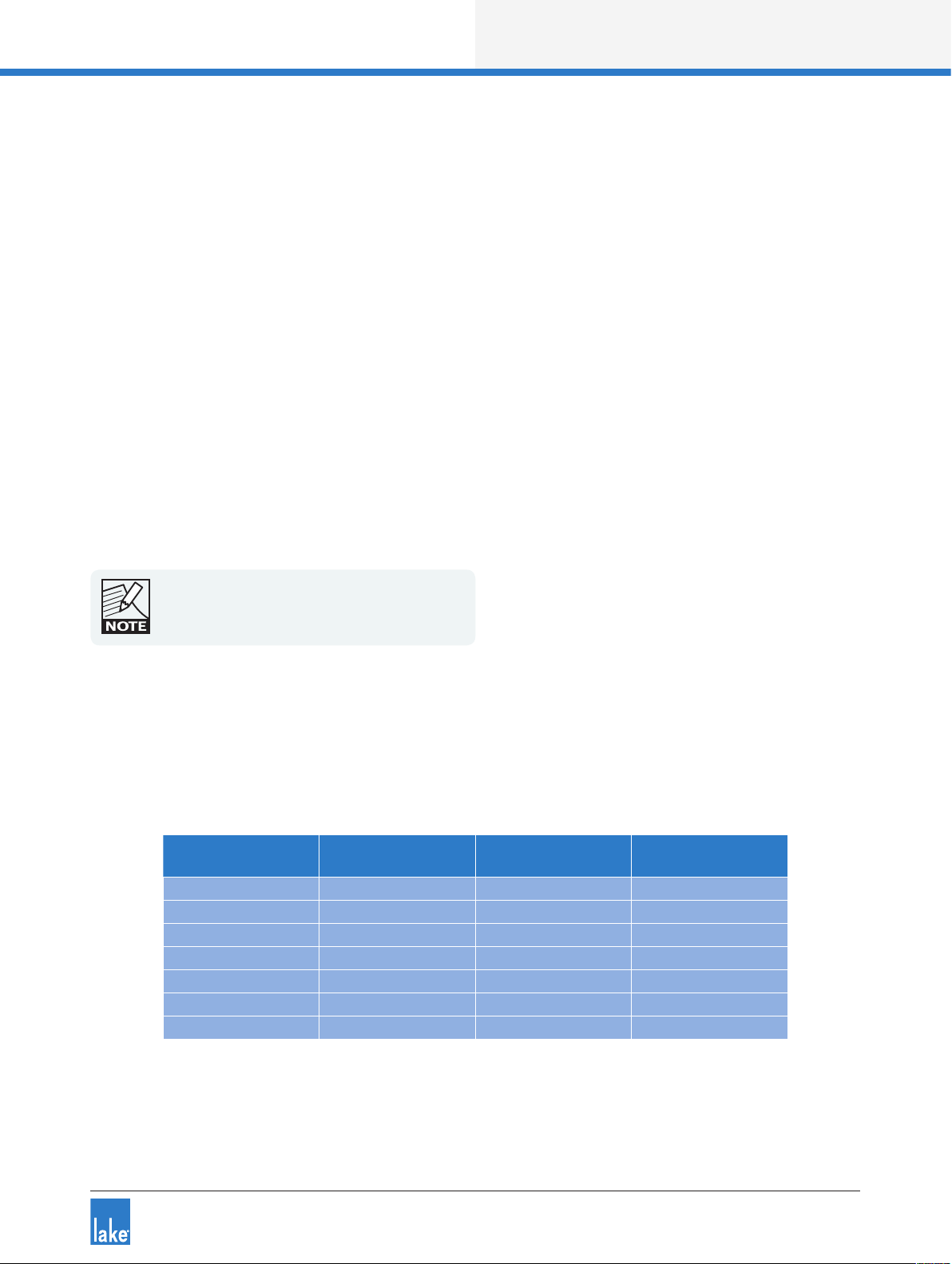
Application Guide
When using automatic detection, the AES3 digital input is monitored and will switch the clock source back
and forth depending on the availability of an AES3 signal.
Please refer to the Lake Controller Operation Manual for additional information.
9.4.3 Dante Clock Conguration
Dante uses its own digital clocking technology across the Ethernet network to ensure that all Dante devices
are synchronized. As part of this logic, an order of priority is dened to identify which device becomes
the Dante Master. A Dante-capable device with a valid BNC Word Clock is chosen as the highest priority,
followed by a device with a valid AES3 signal, then SPDIF, then an internally generated clock.
Dante only operates at 48 kHz or 96 kHz, and therefore only uses the Primary Digital Clock to lock the
sample rate for the Dante Master. The Primary Clock on all Dante Slaves will be overridden by the Dante
Clock. If an additional digital input signal is required on a device that is already a Dante slave, this secondary
digital input must be locked using the SRC clock.
The front panel I/O Status View indicates if that device is selected as Dante Clock Master. Conrmation of
Dante Master / Slave status is also displayed in the Lake Controller.
For further information on Digital Clock conguration and the Lake Controller user interface, please
refer to the Lake Controller Operation Manual.
9.4.4 Signal Processing Latency
The information in Table 9-1 lists the total latency for common input-output congurations when the audio
passes through the Module processing. Table 9-2 on page 60 shows the latency when congured as passthru (no Module processing).
Input
Conguration
Analog Analog 1.039 1.049
Analog 48 kHz sync 1.185 1.185
Analog 96 kHz sync 0.971 0.971
48 kHz sync Analog 1.208 1.219
48 kHz sync 48 kHz sync 1.358 1.358
96 kHz sync Analog 0.951 0.962
96 kHz sync 96 kHz sync 0.871 0.871
Output
Conguration
LM 26
Total Latency (ms)
LM 44
Total Latency (ms)
Table 9-1: Latency for Common I/O Congurations (via Module)
Lake LM Series Operation Manual Rev 1.2.8
59
Page 66

Application Guide
Input
Conguration
Analog Analog 0.226 0236
Analog 48 kHz sync 0.373 0.373
Analog 96 kHz sync 0.158 0.158
48 kHz sync Analog 0.395 0.406
48 kHz sync 48 kHz sync 0.545 0.545
96 kHz sync Analog 0.138 0.150
96 kHz sync 96 kHz sync 0.059 0.059
Table 9-2: Latency for Common I/O Congurations (Pass-thru)
Output
Conguration
LM 26
Total Latency (ms)
LM 44
Total Latency (ms)
60
Lake LM Series Operation Manual Rev 1.2.8
Page 67

LM 26 Technical Specications
10. LM 26 Technical Specications
2-in /6- out or 4-i n/4 -out digita l audio proce ssor
2 Contou r Module s or 4 M esa Mo dules
Raised C osine M esa and I deal Grap hic input equalizer s
Linear phase and classic crossovers and output EQ
LimiterM ax pea k and R MS limite r
Delay, mute, ph ase, gain
Audio Per formance
Internal sam ple rate 96 kHz
A/D an d D/A conversio n resolutio n 24 bit
Internal data p ath 32 bit floati ng point
Product prop agation delay, best c ase (96 kHz A ES to 96 k Hz AES) 0.871 ms
Product prop agation delay, anal og (Analo g in to Analog o ut) 1.039 ms
Maximu m available del ay 2 seconds
Analog
Inputs an d Output s 2 inputs, 6 outputs
Dynamic range, inp uts 116 dB
Dynamic range, ou tputs 115 dB
Frequency response, analog to digital
Frequency response, digital to analog
THD + Noise, inputs
THD + Noise, outputs
Iso- Float gro und isola tion Yes, separate s etting for i nput and out put
Input sen sitivit y settin gs 12 or 26 dBu
Maximu m outpu t level 21 dBu
Input imped ance 20 kOhm ba lanced, 10 kO hm unbalan ced
Commo n Mode Reje ction (CMR) >70 dB, 20 Hz to 20 kH z
Crosstalk -98 dB, 2 0 Hz to 20 kHz
AES3
Inputs an d Output s 4 inputs, 8 outpu ts
Suppor ted resolu tions Up to 24 bit
Suppor ted sampl e rates 44.1, 48, 88.2, 9 6, 176.4, 192 kHz
Termination Selectab le
Dante A udio N etwork
Inputs an d Output s 4 inputs, 8 out puts
Suppor ted sampl e rates 48, 96 k Hz
Suppor ts redundant pa ths Yes
Flexible top ology Yes
Networ k latency 0.5, 0.8, 1.3 , 4 ms
Front Pan el User I nterf ace
Display Daylight readab le monoch rome
Meters LED meters a nd clip indicato rs per chan nel
Mute acces s Mute butto n and LED ind ication pe r channel
LED Fault an d Warning indic ation Yes
Parameter adj ustment Rotary e ncoder
Standby Powe r button On /Standby
Back Pan el Inte rface
Analog inp uts and outp uts 2 + 6 XLR
AES inputs a nd outputs DB-2 5
Ethernet Dual Neut rik ether CON
GPIO DB- 9
Power Locking 3 -pin IEC
Control an d monitorin g interface V ia Ethernet f or Lake Con troller sof tware
Ethern et
Gigabit Ethe rnet 1000 Base-T
Fast Ethern et 100 Base -Tx
GPIO
Inputs 2 General Pu rpose Inpu ts (GPI) suppor ting exter nal contact c losure
Outputs 2 General Pu rpose Out puts (GPO) with i nternal con tact closure
Softw are configura ble input co ntrol Standby sta te, Mute state, Du al Preset reca ll
Softw are configura ble output i ndication Standby sta te, Mute state, Fau lts, Ready
Device P reset s
Frame presets 100
Power
Nominal vo ltage 100-240 VAC
Operating vo ltage 70-26 5 VAC
Power consu mption 30 W ma ximum
Dimens ions W: 48 3 mm (19”), H: 44 mm (1 U), Overall D: 2 90 mm (11.5”)
Weight 5 kg (11 lbs.)
Finish B lack painted ste el chassis w ith aluminu m handles
Approva ls CE, ANS I/UL 6 006 5 (ETL), C SA C22. 2 NO. 60 065, F CC
+/-0.1 dB, 20 Hz to 2 0 kHz
+/-0.0 3 dB, 20 H z to 20 kHz
0.00 024% at 1 kHz
0.00 037% at 1 kHz
Specifica tions su bject to c hange w ithout n otice
Lake LM Series Operation Manual Rev 1.2.8
61
Page 68

LM 44 Technical Specications
11. LM 44 Technical Specications
Lake fea tures
Module co nfiguration 2 Conto ur or 4 Mesa mo dules
Processing c hannels 6 in Contour m ode, 4 in Mesa m ode
Input routers 8 input routers w ith 4 priorities in each, sea mless failove r to lower priori ties
Module Inpu t mixer 4 ch. for Contour, 8 ch. for M esa-mo dules. Mix any ra tio betwee n all input route rs.
Input proces sing Parameteric EQ wi th Mesa and Id eal Graphic eq ualizers, bot h utilizing Rais ed Cosine algorithms
Output proc essing L inear phase or Classic cros sovers, Parametric EQ, shel ving and all- pass filters
Features Delay, Mute, Phase, G ain etc.
Limiters LimiterMax with Peak and RMS limiter. Configurable MaxRMSLevel, MaxRMSCorner, MaxRMSAttack,
SuperMo dule com patible Yes
Audio Performance
Conversion resolution 24-bit
Internal sample rate 96 kHz
Internal data path 32-bit floating po int
Product pro pagation d elay Best case (AE S synchronous 96 kHz to A ES synchronous 96 kHz v ia module) 0.871 ms
Maximu m available user d elay 2 seconds
Analog
Inputs and Ou tputs 4 inp uts, 4 output s
Frequency R esponse, analog- to-digit al +/-0.1 dB, 20 Hz to 2 0 kHz
Frequency R esponse, digital-to -analog +/-0.1 dB, 20 Hz to 20 kHz
THD+Noi se, Inputs 0.00024% ty pical at 1 kHz
THD+Noi se, Outputs 0.00 037% typi cal at 1 kHz
Dynamic Ra nge, Inputs 116 dB
Dynamic Range, Ou tputs 115 dB
Input Imp edance 20 kOhm bal anced, 10 kOh m unbalanced
Output I mpedance 50 ohm
Maximu m Input level +26 d Bu
Input Sensi tivity - set tings for digital full-s cale +12 dBu, +26 dBu
Maximu m Output level +21 dBu
Crosstalk, I nputs -98 dB, 20 Hz to 2 0 kHz
Crosstalk, O utputs -98 d B, 20 Hz to 20 kHz
Common M ode Rejection Ratio (CM RR) >70 dB, 20 Hz to 20 kH z
AES3/ EBU (sample rate c onverte rs available as des ired)
Inputs and Ou tputs 8 inp uts, 8 output s
Supporte d sample rates 44.1 kHz, 48 kHz, 8 8.2 kHz, 96 kHz, 176.4 kHz, 19 2 kHz (I/O indiv idually sele ctable)
Supporte d resolutio ns Up to 24-bi t
THD+Noi se 0 .000 02 % at 96 kHz and 0.00 006 % at 44.1 kHz sample rate
Dynamic Ra nge B ase48 -140 dBF S, Base44 -125 dBFS
Clockin g
Clock selec tion Manual or au tomatic acco rding to priorit y scheme
Oscillator t ype / Synchr onization High qualit y VCXO clock can provide Dante maste r clock or slave. Au tomatic synchronizatio n with Dante net work.
Base48 2 (Primary a nd SRC)
Base44 1 (SRC)
Clock accurac y < ± 7 ppm
Dante (Aud io Network)
Inputs and Ou tputs 4 inp uts, 8 output s
Supporte d sample rates 48 kHz, 9 6 kHz
Support re dundant paths Glitch-fre e Dual Redun dant Dante usin g two Ethern et networks
Receiver late ncy 0.5 ms, 0.8 ms, 1.3 m s, 4 ms
GPIO
Inputs 2 G eneral Purpose Inputs (GP I) supporti ng external c ontact closu re
Outputs 2 General Pu rpose Outp uts (GPO) with inte rnal contact c losure
Softwa re configurabl e input contro l Standby state, Mu te state, Dual pres et recall
Softwa re configurabl e output indi cation Standby st ate, Mute state, Faults, Ready
Device p resets
Frame presets 100
Power req uirements
Nominal Volt age 100-240 VAC
Operating Volt age 70-265 VAC
Power consu mption 30 W maximum
Front pa nel int erfac e
Display Daylight re adable mono chrome (128 x 64)
Meters LED for signal level and clip indicators per channel
Mute acces s Dedicated Mute button and LED indication per processing channel
Menu Intuitive and p owerful us er interface w ith soft keys
Status in dication LED Faul t and Warning indi cation and det ailed description on displ ay
Parameter A djustment Single /multiple parameter edits w ith rotary e ncoder
Back Pane l Interface
Analog Inp uts and Outpu ts 4 + 4 XLR
AES Inputs a nd Outputs DB-25 , with select able terminat ion
Ethernet Auto 100/10 00, Auto uplink, 2 x Neut rik etherC ON RJ45 c onnectors
GPIO DB -9
Power D etachable locking 3 -pin IEC
Control and m onitoring interface Via Ethernet f or Lake Cont roller soft ware, or DLM (the 3rd part y protocol)
Dimens ions (W/ H/D) 483 mm (19"), 44 m m (1 U), 290 mm (11.5")
Weight 5 Kg (11 lbs.)
Finish Black painted steel c hassis with c ast alumimu m handles
Approval s C E, ANSI/UL 60 065 (ETL), CSA C2 2.2 NO. 6006 5, FCC
Warrant y 3 years, com ponents and factory wor kmanship; see f ull warranty statement
Specif ications subje ct to chang e without notice
MaxRMSRelease and MaxPeakLevel
Analog (An alog in to Anal og out via mo dule) 1.049 ms
Pass thru (Ana log in to AES synchronous 9 6 kHz bypassing module) 0.158 ms
62
Lake LM Series Operation Manual Rev 1.2.8
Page 69

Warranty and Support
12. Warranty and Support
12.1 General
This product is manufactured by Lake, and it is warranted to be free from any defects caused by components or factory workmanship, under normal use and service, for a period of three (3) years from date of
purchase from an authorized Lake dealer.
If the product fails to perform as specied during the warranty period, Lake will undertake to repair, or at its
option, replace this product at no charge to its owner, provided the unit is returned undamaged, shipping
prepaid, to an authorized service facility or to the factory.
This warranty shall be null and void if the product is subjected to: repair work or alteration by a person
other than those authorized by us; mechanical damage including shipping accidents; war, civil insurrection,
misuse, abuse, operation with incorrect AC voltage; incorrect connections or accessories; operation with
faulty associated equipment; or exposure to inclement weather conditions. Damage due to normal wear and
tear is not covered by the warranty. Units on which the serial number has been removed or defaced will not
be eligible for warranty service.
Lake shall not be responsible for any incidental or consequential damages. Lake’s responsibility is limited
to the product itself. Lake takes no responsibility for any loss due to cancellation of any events, or rent of
replacement equipment or costs due to a third party’s or customer’s loss of prot, or any other indirect cost
or losses however incurred.
Lake reserves the right to make changes or improvements in design or manufacturing without assuming any
obligation to change or improve products previously manufactured.
This warranty is exclusive, and no other warranty is expressed or implied. This warranty does not affect the
customer’s statutory rights.
12.2 International Warranties
Please contact your supplier or distributor for this information, as rights and disclaimers may vary from
country to country.
12.3 Technical Assistance and Service
12.3.1 International Service
If your Lake product requires repair, contact your Lake dealer or distributor, or contact Lake by fax or email to
obtain the location of the nearest authorized service centre.
Lake LM Series Operation Manual Rev 1.2.8
63
Page 70

Warranty and Support
12.3.2 Factory Service
In the event a Lake product requires factory service, you may contact Lake’s service department for return
instructions and a Return Authorization number.
Please note for product return:
1. Use the original packing.
2. Include a copy of the sales receipt, your name, return address, phone and fax number, email address
and description of the defect.
3. Mark the Return Authorization number on the outside of the packing.
4. Ship the product prepaid to:
Lake
Faktorvägen 1
SE-434 37 Kungsbacka
SWEDEN
Phone: +46 300 56 28 00
Fax: +46 300 56 28 99
service@lakeprocessing.com
www.lakeprocessing.com
12.4 Trademarks
Lake is a national and/or international registered trademark of Lab.gruppen AB. LM, PLM, Loudspeaker
Management and Powered Loudspeaker Management are trademarks of Lab.gruppen AB.
Dolby is a registered trademark of Dolby Laboratories. Raised Cosine Equalization, LimiterMax and Iso-Float
are trademarks of Dolby Laboratories. Audinate is a registered trademark of Audinate Pty Ltd. Dante and Zen
are trademarks of Audinate Pty Ltd.
All other trademarks remain the property of their respective owners.
Copyright © 2011 Lab.gruppen AB. All rights reserved.
64
Lake LM Series Operation Manual Rev 1.2.8
Page 71

I N T E R N A T I O N A L C O N T A C T ► I N F O @ L A K E P R O C E S S I N G . C O M U S & C A N A D A C O N T A C T ► I N F O @ T C G - A M E R I C A S . C O M
W W W . L A K E P R O C E S S I N G . C O M
L A K E I S A W H O L L Y - O W N E D S U B S I D I A R Y O F L A B . G R U P P E N A B , S W E D E N
W W W . L A B G R U P P E N . C O M
 Loading...