

Page 1

USER MANUAL HEADLINES
Unpacking 2
Warnings 2
User responsibility 2
1. Speaker damage
2. Speaker output hazard.
3. Radio interference.
Introduction 3
1. Front panel
2. Rear panel
Installation 4
1. Mounting
2. Cooling
3. Operating voltage
4. Grounding
5. Power consumption
6. Input connections
7. Connecting speakers
Operation modes 6
1. Stereo
2. Tandem mono
3. Bridged mono
4. Stereo reverse
Operation 7
1. Operation precautions
2. Input attenuators
3. Gain switch
4. Indicators
Protections 8
1. Clip-limiter
2. Thermal protection
3. VHF protection
4. Short circuit protection
5. D.C. protection
Unpacking
USER MANUAL
LAB 500
Design features 9
• Cooling
•
Safety approvals
• EMC approvals
Specifications 9
• EMC-declaration
Appendix A 10
• Mains voltage selection
Maintenance 10
Troubleshooting 10
Warranty and disclaimers 11
• General
• International
Technical assistance and services 11
• International
• Factory services
1
Page 2

Carefully open the shipping carton and check for
any noticeable damage. Every LAB.GRUPPEN
amplifier is tested and inspected before leaving the
factory and should arrive in perfect condition. If
found to be damaged, notify the shipping company
immediately. Only the consignee may institute a
claim with the carrier, for damage incurred during
shipping. Be sure to save the carton and packing
materials for the carrier's inspection.
It is also advisable, to save the carton and packing
material, even if the amplifier is undamaged.
Should you ever need to ship the amplifier, use the
original packing.
Warnings
Read this before you are operating your amplifier:
• Do not use this amplifier if the power cord is
broken or frayed.
• Always operate the unit with the chassis
ground wire connected to the electrical safety
earth.
• Do not parallel or series connect an amplifier
output, with any other amplifier output. Do not
connect the amplifier output to any other
voltage source, such as battery, mains source,
or power supply, regardless of whether the
amplifier is turned on or off.
• Do not run the output of any amplifier back
into another channel's input.
• Do not block the air intake or exhaust ports.
Do not operate the amplifier near heat
producing devices such as radiators, stoves etc.
• Do not spill water or other liquids into or on
the unit. Do not operate the amplifier if
suspected or standing in liquid.
• Do not remove top or bottom covers. Removal
of the cover will expose hazardous voltages.
There is no serviceable parts inside and
removal may void warranty.
• Keep this manual for future reference.
User responsibility
1. Speaker damage
Your amplifier is very powerful and can be
potentially dangerous to both loudspeakers and
humans alike. Many loudspeakers can be easily
damaged or destroyed by overpowering, especially
with the high power available from a bridged
amplifier. Always check the speakers continuous
and peak power capabilities.
Even if the gain is reduced by using the
amplifier's front panel attenuator, it is still possible
to reach full output power, if the input signal level
is high enough.
2. Speaker output hazard
Power amplifiers are capable of producing
hazardous output voltages. To avoid electrical
shock, do not touch any exposed speaker wiring,
while the amplifier is operating. See page 6 about
outputs for proper connection of speakers.
3. Radio interference
This product has been tested, and complies with the
limits for the European Electro Magnetic
Compatibility (EMC) directive. These limits are
designed to provide reasonable protection against
harmful interference between electrical equipment.
However, there is no guarantee for no interference
even if the amplifier is EMC approved.
If the amplifier cause interference, which can be
easily determined by turning the amplifier on and
off, the user can correct the interference by one or
more of the following steps:
1. Increase the proximity between the equipment.
2. Connect the AC cord to an outlet on a different
circuit from that to which the affected unit is
connected.
3. If a radio receiver is interfered (normally
amplitude modulation); reorient the antenna.
4. Check if the affected unit complies with the
EMC limits for immunity, (CE-labelled).
If not, address the problem with the
manufacturer or supplier. All electrical products
sold in the EC must be approved for immunity
against electromagnetic fields, high voltage flashes,
and radio interference.
2
Page 3
Introduction
Thank you for purchasing a LAB.GRUPPEN power amplifier. This manual contains important information on
operating your amplifier correctly and safely. Please take some time and read this manual to familiarize yourself
with the amplifier.
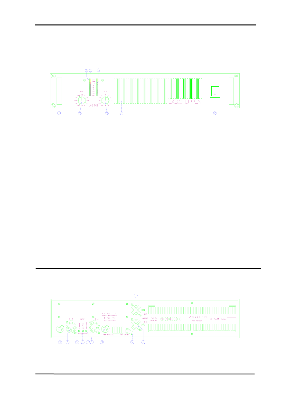
The front panel
Figure 1. Front panel
1. Carry/protection handle
Both handles can be used to carry the amplifier,
they also act as protection for the front panel. If so
desired they can be removed (by removing the
screws behind the front panel) for fixed installations,
or racks where the front covers are to shallow.
2. Input level attenuators
These controls are used to alter the signal level
entering the amplifier. They are calibrated in dB to
help set up active loudspeaker systems or cut down
unwanted noise from the input signal.
(See page 7).
3. Over temperature protect indicator.
This indicator is lit if the amplifier tries to
operate above its maximum operating
o
temperature(90
C). The indicator first comes on as a
warning to either turn down the input level or check
the cooling arrangements after which point the
amplifier will mute the input signal.
The rear panel
When the cooling fan have returned the output
heat sinks to the normal operating temperature the
input signal is unmuted.
4. VHF protection indicator
This indicator lights when constant signals,
above 20 kHz at full power, are present at the output
terminals. When this happens the input signal is
muted and the process cycles until the VHF signal is
no longer present. (See page 8).
5. Clip/limit indicator
This indicator tells when the amplifier output is
clipping or limiting.
6. Fan grill filter.
A foam filter is located behind the front panel to
prevent dust entering the amplifier.
7. Power actuator
This is used to start the amplifier. (See page 4 and 7).
Figure 2. Rear panel
3
Page 4

Please refer to diagram on page 3
1. Speaker connector
This type of speaker connector may be
unfamiliar to some users. A full description is found
in the operation section. (See page 6).
2. AC line cord (See page 5).
3. Input jack
Alternative to using input XLR or for linking
inputs with other amplifiers. (See page 5).
4. Input signal XLR (See page 5).
Installation
1. Mounting
The amplifier is two rack units high (2U) and will
mount in a standard EIA 19 inch rack. Amplifiers
may be stacked directly on top of each other. There
is no need for spacing between units. If it is the
intention to fill a rack with amplifiers, we
recommend racking is started from the bottom of
the rack. It is also recommended that rear supports
are used for amplifiers mounted in the middle of the
rack, especially if used as part of a portable system.
2. Cooling
Your amplifier uses forced air cooling system to
maintain a low and even operating temperature. All
Lab.gruppen amplifier, which are fan ventilated,
have front to rear cooling. There are several reasons
for this, one is that there's usually cooler air outside
the rack than inside and therefore the amplifiers can
run at higher continuos power levels without
thermal problems. Never try to reverse the air flow,
as the Intercooler® need a pressure chamber
between the fan and heat sink, and this only works
in one direction of the air flow (see Design features
on page 8).
Should a heat sink get too hot, its sensing circuit
will mute the hot channel. If the power supply
overheats, another sensing circuit will mute all
output channels, until it cools down to a safe
operating temperature.
Make sure that there is an adequate air supply in
front of the amplifier and that the rear of the
amplifier has sufficient space to allows the exhaust
to escape. If the amplifier is rack mounted, do not
use covers or doors on the front or rear of the rack.
For fixed installations with a central cooling
system, usually found in fixed installations with a
dedicated rack room, it may be necessary to
5. Phase reverse switch for channel B
For reversing the input signal phase of channel
B to allow bridged operation. (See page 7).
6. Link switch
Allows a single input to drive both channels
simultaneously. (See page 7).
7. Gain select switch
Allows amplifier gain to be switched between
29dB and its normal gain at 0.775mV input
sensitivity. (See page 7).
calculate the maximum heat emission. Refer to
Power consumption on page 5.
3. Operating voltage
A label just below the mains cable on the rear of
the amplifier indicates the AC mains voltage, for
which the amplifier is wired. Connect the power
cable only to the AC source referred to on the lab el.
The warranty will not cover damage caused by
connecting to the wrong type of AC mains.
For converting a 230 volt amplifier to 115 volt or
vice-versa, see Appendix A.
The amplifier is supplied with an approved European
AC line connector. If this connector is not
appropriate for your country, it can be cut off and
wired to a suitable connector in the following way :
BROWN LIVE
BLUE NEUTRAL
GREEN/YELLOW EARTH
Once the AC connector is connected to a suitable AC
supply, the amplifier can be started with the AC
actuator.
When you power up the amplifier, the fan then blow
at high speed before going onto "idle" and the 2
bottom green LED’s come on to show the output
circuits are receiving the correct rail voltage.
4. Grounding
There is no ground lift switch or terminal on this
amplifier. The signal ground is always floating via a
resistor to chassis and the grounding system is
automatic. If a potential above 0.6V presents itself
between signal ground and chassis ground, a short
circuit is introduced between the two, thereby
enabling electrical protection. If a unit in the system
is faulty, its mains fuse will blow, due to this
automatic ground system.
4
Page 5

If however you wish to tie the signal ground to
chassis, connect the XLR-connector’s shell lug to
pin 1. In the interest of safety never disconnect the
earth pin on the AC cord.
For all units that are EMC approved (radio
interference), there is an AC mains filter. This filter
needs the chassis ground for reference, otherwise a
current loop is formed via the signal ground.
Use the balanced input to avoid hum and
interference.
5. Power consumption
There are three ways to determine the
power/current consumption of the amplifier:
First, the peak current draw at full output
power. Under this condition the power will trip the
thermal limiting protection within less than 2
minutes. During this time, the temperature of the
power supply will be stabilised at a temperature
that will have no effect on the insulation rating o f
the AC line cord.
Table 1.
MAX OUTPUT POWER MAINS INPUT POWER
Power Full Power 1/3 Power 1/8 Power Idle
LAB 500
8 ohms 2X 180 700 500 200 100
4 ohms 2X 260 1000 700 300 100
2 ohms 2X 320 1600 800 400 100
Secondly, the maximum expected average
current under worst case program material which is
1/3 of full power according to the FTC-standard. At
this level the music will be in the state of constant
clip and is therefore the highest power level one
can obtain without completely obliterating the
program.
At last, the "normal operating power", as
measured according to the safety standard IEC 65
and used by a majority of safety agencies. The
normal operating power is measured using pink
noise, with an average output power equal to 1/8 of
full power. The one eighth of the total power is as
loud as you can play music while making some
attempt to avoid obvious clipping. It also
corresponds to a headroom of 9dB, which is very
low for an audio program.
In 2 ohms operation, the protection of the amplifier
circuit will not permit long term current draw and
the component temperature rise will stabilises well
below the rating.
sine wave note 1 note 2
note 1
Mean power with music as program source Normal" music power with 9dB headroom,
The amplifier driven to clip level
note 2
IEC standard power rating.
The current draw can be calculated by dividing the mains input power by the mains voltage.
We recommend you to design the power distribution for at least the current at 1/8 power and 1/3 power for
heavy duty demands like discos etc.
The heat power can be calculated as the following example:
We consider a headroom of at least 9dB and a 4 ohms load on an amplifier producing 260 watts per channel.
The 1/8 power per channel is then; 260 / 8 = 33 watts, total output; 2 x 33 = 66 watts.
The power consumption according to the chart above is then 300 watts.
The heat power produced is the difference between the power consumption and output power;
300 - 66 = 234 watts per amplifier.
6. Input connections
XLR Input connectors are balanced and wired
according to the IEC 268, that is pin 2 hot, and wired
in the following way:
PIN 1 GROUND/SHIELD
PIN 2 HOT
There are also TRS jacks for linking etc. They are
wired as follows:
TIP HOT
RING COLD
SLEEVE SHIELD/GROUND
PIN 3 COLD
Figure 4. TRS phone plug
The input impedance is high enough (20 kohms
balanced) to allow ”daisy-chaining”, or multiple
Figure 3. XLR input connector pinout
parallel input connections. To daisy chain, use the
TRS jacks provided on each channel. The input
circuits also have a high enough headroom, to accept
the maximum output level from virtually any low
level signal source.
5
Page 6

Figure 5. Rear panel connectors
Do not use XLR and TRS jacks on the same
channel simultaneously for mixing or other
purposes.
Figure 6. Balanced line
To connect an unbalanced source, tie pin 3 (ring on
TRS jack) down to the shield of the connector. If you
leave one pin disconnected, you will lose 6 dB in
gain.
Figure 7. Unbalanced line connection
A more optimal method for handling unbalanced
sources is shown in Figure 8. This is similar to the
connection for balanced lines, but pin 3 is tied down
to shield, at the source side instead. The hum and
noise rejection for the cable is equivalent to that for a
balanced line. To minimize hum in the audio, use
balanced inputs whenever possible.
Operation modes
1. Stereo operation
For stereo (dual channel ) operation, leave the Link
and Phase reverse switches in the undepressed
position. In this mode, both channels operate
independently of each other, with their level
attenuators controlling their respective levels.
Fi
gure 8. Balanced line with unbalanced equipment
7. Connecting speakers
Speaker connections are made via the two Neutrik
NL4FC Speakon connectors (1).
They are the only connectors currently available to
meet the EC safety requirements. They are wired in
the following manner:
Pin -1 Speaker ground.
Pin +1 Speaker positive.
Pin -2 No connection.
Pin +2 No connection.
Figure 9. Speakon connector
Please note that this is the standard wiring
convention for Speakon connectors adopted worldwide.
Never connect either output terminal to ground
or to some other output or input terminal (see
warning on page 2).
For normal two-channel operation, connect each
speaker load across the outputs positive and ground
terminals. Pay attention to speaker polarity;
loudspeakers connected out of polarity degrade
sound quality and may be damaged as a
consequence.
Keep the speaker cable wires as short as possible,
and use a good quality stranded speaker cable. Do
not use shielded wire, such as microphone or guitar
cable. Remember that the speaker cable robs the
power of the amplifiers in two ways:
Increases the load impedance and introduces
resistive power losses, so called I
2
R losses.
Never connect either output terminal to ground
or in parallel. The recommended minimum
nominal impedance, for stereo or tandem operation,
is 2 ohms per channel.
6
Page 7

2. Tandem mono
For tandem ( dual channel-single input) operation ,
depress the Link switch. Both channels can now be
driven by a signal, at either input connector. The
output connection is the same as in stereo mode.
You can use either TRS connectors for linking out
etc. Do not use the remaining XLR and TRS
connectors for mixing or other purposes. Both
level attenuators are active, allowing you to set
different levels for each channel.
Never connect either output terminal to ground
or in parallel.
3. Bridged mono
To bridge the amplifier, depress the Link switch (6)
and Phase reverse switch (5). Both channels are then
driven by a single signal at either input. You can
use any remaining input connectors for linking etc.
Do not use the remaining XLR and TRS as input
jacks simultaneously for mixing or other purposes.
To obtain an output, connect the speaker leads to pin
+1 on channel A Speakon to speaker positive
terminal and pin +1 on channel B Speakon to
speaker negative terminal . Do not connect either
of the -1 (negative) pins of the Speakons. Do not
connect speakers to channel A or B in the normal
manner in bridge mode, as this can cause serious
damage.
Figure 10. Bridge mono connection
Operation
1. Operation precautions
• Make sure that the power switch is off before
making any input or output connections or
operating the switches on rear panel. See pages
4-5 about installation.
• Make sure that the AC mains is correct and the
same as that is printed on the rear panel of the
amplifier. See pages 4-5 , about operating
voltage and power consumption.
• Make sure that the switches on the rear panel
for operation modes are in the correct position.
See pages 6-7, about operation modes .
• It is always a good idea to turn down the gain
controls during power up, to prevent speaker
damage, if there is a high signal level at the
input.
The recommended minimum nominal impedance
for bridged mono is 4 ohms (equivalent to driving
both channels at 2 ohms).
Driving bridged loads of less than 4 ohms may cause
a thermal overload.
Both level attenuators must be at the same position.
We recommend you to put them in the 0 dB (full)
position.
4. Stereo reverse
This mode is similar to the Tandem mono mode.
Apart from depressing the Link switch , you also
depress the Phase reverse switch, like in the Bridge
mono. Channel B is now phase reversed. To
compensate for that, connect pin +1 on channel B
Speakon to speaker negative terminal and pin -1
on channel B to speaker positive terminal.
Figure 11. Stereo reverse mode
Channel A output is connected as in the normal
stereo mode. By having channel A and B operating
in opposite polarity, the energy storage in the
power supply is more efficient. This means that the
amplifier can deliver up to 10% more power than in
tandem mono mode. This is significant for signals
below 100 Hz (sub bass etc.).
2. Input attenuators
The two input level attenuators on the front
panel, alter the signal level for their respective
amplifier channel in all modes. They are calibrated in
dB to help setting up active loudspeaker systems or
cutting down unwanted noise from the input signal.
In bridged mode, both controls must be in the same
position, so that the speaker load will be shared
equally between the channels.
3. Gain switch
The gain switch located on rear panel is for
changing the input sensitivity of the amplifier. This
can be handy when using low or high nominal input
signals e.g. most professional mixing consoles
operate at a nominal level of +4dBu therefore use the
29dB position (depressed switch), to give you plenty
of fader movement. On the other hand, for a disco
mixer that operates at a nominal level of 0dBu, use
7
Page 8

the upper position setting, which has a sensitivity of
0 dB for full power in 4 ohms.
Figure 12. Front indicators
Protection features
Each LAB.GRUPPEN amplifier has many advanced
protection features, that will protect both the
amplifier and the speakers connected to it, should a
fault condition arise. Under normal use these features
are inaudible. All protection circuits are independent.
Clip limiter
The clip limiter is included to prevent dangerous clip
signals reaching the speaker and damaging it. It
works by monitoring the output and comparing the
distortion produced between the input and output of
the amplifier. If the distortion exceeds 1%THD for
any reason ( voltage or current clipping), the limiter
reduces the input signal proportionally. Note that, if
the signal is distorted or clipped before it reaches the
amplifier, the clip limiter will not be activated. Under
normal operation the clip limiting is inaudible.
As a by-product, when the amplifier comes out of a
protect condition, the output level has a slow rise
time -the effect is like turning the gain up slowly.
Thermal protection
When the amplifier is driven very hard into low
impedance, the cooling fan go into high speed. If the
conditions that cause this continue, the temperature
indicator(s) will light as an indication that the
amplifier will soon thermal out. After five seconds
the amplifier will go into thermal protect, by muting
the input signal.
4. Indicators
The two bottom green ”ON” LEDs indicate that the
output circuits are receiving the correct rail voltage.
The ”-25 dB” LEDs glow when the output signal is
greater than -25dB, 0dB is referenced to full output
power. These LEDs also act as signal present
indicators. The rest of the green LEDs forms a bar
for output levels from -20dB to -5dB.
The Clip/limit indicator tells when the amplifier
output is clipping or limiti ng.
The remaining yellow LEDs indicate if any
protection circuits are activated. These are described
below.
After 15-20 seconds the amplifier will cool down
the Intercooler
Thermal protection starts when the Intercooler
®
and the cycle will begin again.
®
reaches a temperature above 900 C
VHF protection
When a signal of more than 20khz, at full output
power, is present at the output connectors for more
than five seconds, the VHF protection mutes the
input signal (this is indicated on the front panel (4)
labeled VHF). After five seconds the cycle starts
again.
If the VHF protection is required to be turned off i.e.
for studio monitors, please consult your supplier, as
this is a non-user adjustment.
Short circuit protection
All LAB.GRUPPEN amplifiers are completely
short circuit protected. The protection circuit
permits very high peak currents, but still holds the
output devices within the safe operation area. If a
short circuit is maintained, the channel affected will
eventually go into thermal protection and the cycle
will start again.
D.C. protection
There are two types of DC protection:
Fuses on the supply branches of each channel (this is
an IEC 65 requirement).
A Crowbar bar protection that shorts the output. Bot h
these circuits come into effect once a DC level of 10
volts or more is detected on either channel.
8
Page 9

Design features
Cooling
The LAB.GRUPPEN amplifier runs very cool due
to a patented heat sink called Intercooler
output devices (bi-polar) are mounted directly on a
copper heat sink thereby avoiding thermal losses
normally found when using mica washers (the heat
sink is mounted horizontally in front of a pressure
chamber) The air flow is constant along the whole
heat sink, thanks to a horizontal pressure chamber in
front of it, (in a conventional tunnel design the end of
the heat sink opposite to the fan invariably gets hotter
than that directly in front of the fan). When cool air
hits the geometric fins of the Intercooler
turbulence is produced thereby enabling efficient
cooling.
Safety approvals
Lab.Gruppen amplifiers are designed to meet the
IEC65, a stringent electrical safety approval from the
International Electro-technical Commission. The
IEC65 is recognized world-wide with most countries
having an equivalent.
EMC approvals
EMC stands for Electro Magnetic Compatibility. This
implies that the equipment should have low emission
of radio frequencies, directly as electromagnetic fields
in the air, and as conducted from the cables from and
to the unit. The unit should also be able to handle
electromagnetic fields, high voltage flashes, and radio
interference, coming into the unit via the air or cables.
Emission
The regulation now cover the frequency range from
150 kHz to 300 MHz. The maximum level radiated
from a unit has to be below 100 μV, ( 0.0001 V ).
TM
. The
TM
,
EMC-declaration
This audio power amplifier conforms with the
EMC-directive 89/336/EEC and relates to the
following standards:
EN 55013:1990
EN 50 082-1
Immunity
The equipment should be able to handle three
different types of interference:
• Electrostatic discharges up to 8 kV, hitting the
chassis or cables.
• Transients and bursts up to 1 kV, conducted
through the cables to the unit.
• Electromagnetic fields up to 3 V/m, radiated on
the unit and the cables in the frequency range of
27 - 500 MHz.
We have extended the tests in two cases and chosen a
standard used for heavy industrial situations. First, we
have tested conducted disturbances in the frequency
range 150 kHz - 80 MHz, by injecting 3V amplitude
modulated (80%) signals into all the cables ( inputs,
outputs and mains ). This covers noise from AM
transmitters, which are still in use in some areas.
Secondly, we have extended the range for
electromagnetic fields to 26 - 1000 MHz, with a level
of 6 V/m and 80% AM modulated.
In the range 895 - 905 MHz, we test with a field
strength of 35 V/m and 100% pulse modulation.
emulate the signals from a mobile phone close to the
unit. In all cases the noise plus distortion is below 1%,
at normal operation level, ( normal operation level is
1/8 of full power or -9 dB under clip point according
to IEC 65).
IEC 801-2, ed.1(1984)
IEC 801-3, ed.1(1988)
IEC 801-4, ed.1(1984)
SS-ENV 50 141 ed.1 (1994)
This
9
Page 10
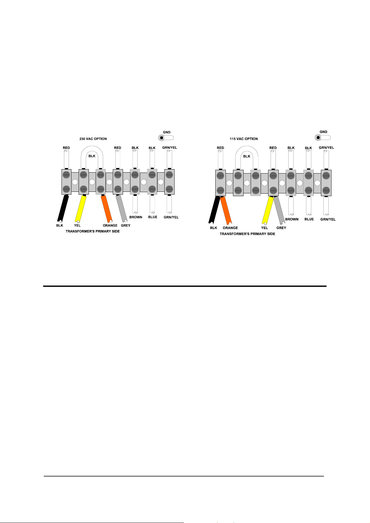
Appendix A
Mains voltage selection
LAB 500 is normally shipped for 230 volt AC
operation only. For export there is a 115/230 volt
AC option available. To check if the amplifier is
equipped with this option, please follow these
steps:
1. Make sure that the LAB 500 is unplugged from
the mains voltage.
2. Remove the top cover.
3. Locate the terminal block for the mains cable.
4. If the transformer’s primary side has two wires
only, the amplifier is for 230 volt operation
only.
5. If the transformer’s primary side has four
wires, the amplifier has the 115/230 volt
option.
6. To select the desired mains voltage, wire the
terminal block as shown in Figure 13 or 14.
7. For 230 volt operation; use a T6.3 A fuse (slow
blow), for 115 volt change to a T10 A fuse
(slow blow).
8. Replace the amplifier top cover.
9. For 115 volt operation; stick a ”115 VAC”
label on top of the 230 VAC label on rear
panel.
Figure 13. 230 VAC wiring
Maintenance
Under normal use the amplifier should give years
of trouble free service. The only user maintenance
required from the user is to vacuum the front grill
periodically.
In some extreme cases it may be necessary for
your supplier to clean the inside of the amplifier.
These conditions usually occur after prolonged use
in environments using "cracked- oil" smoke
machines.
If you are using your amplifier for heavy duty use
i.e. concert touring or industrial music it is
recommended that you have your amplifier
serviced every 3 years, purely as a preventative
measure
Troubleshooting
These are typical things to check if you think your
amplifier is faulty:
Warranty and disclaimers
Figure 14. 115 VAC wiring
Warning: This modification should only
be made of an experienced service
technician.
Fault: No output.
If the output bargraph is functioning there is
nothing wrong with the amplifier, and the likely
cause is an unsecured Speakon.
Check that the VHF protection is not activated. If
it is, remove possible high frequency oscillations
from the relevant input.
Fault: The amplifier goes into thermal protection
when driven at low level.
Check that your loudspeaker has not got a short
circuit in its windings, (this can occur when the
speaker coil gets warm).
Fault: The amplifier does not respond even after
checking above items.
In the unlikely event, that there is a non-user
rectifiable fault, return the amplifier to your
supplier or an approved service centre.
Lab Gruppen cannot be held responsible for
damage or injury, as a result of the top cover
being removed.
• General
10
Page 11

This product is manufactured by LAB.GRUPPEN
and is warranted to be free from defects in
components and factory workmanship under
normal use and service, for a period of one year
from the date of original purchase.
During the warranty period, LAB.GRUPPEN or its
nominated agents, will undertake to repair, or at its
option, replace this product at no charge to its
owner, when failing to perform as specified,
provided the unit is returned undamaged and
shipping pre-paid, to factory or authorised service
facility.
No other warranty is expressed or implied.
This warranty shall be null and void, if the product
is subjected to:
1) Repair work or alteration by person other than
those authorised by LAB.GRUPPEN or its agents.
2) Shipping accidents, war, civil insurrection,
misuse, abuse, operation with incorrect AC voltage,
operation with faulty associated equipment and
normal wear and tear. Units, on which the serial
number has been removed or defaced, will not be
eligible for warranty service.
3) LAB.GRUPPEN shall not be responsible for
any incidental or consequential damages, with
respect to the products warranted.
LAB.GRUPPEN reserve the right to make changes
or improvements in design or manufacturing,
without assuming any obligation to change or
improve products previously manufactured.
• International
Please contact your supplier for this information, as
rights and disclaimers may vary from country to
country.
Technical assistance and services
• International
If your LAB.GRUPPEN product needs repair,
contact your LAB.GRUPPEN dealer or distributor,
or contact LAB.GRUPPEN by fax, to obtain the
location of the nearest authorised service centre.
• Factory services
In the event that your LAB.GRUPPEN product
needs factory service, you shall contact
LAB.GRUPPEN service department for return
instructions and a Return Authorisation number.
Please note on product return:
1. Use the original packing
2. Include a copy of the sales receipt, your name,
return address, phone number, fax number and
defect description.
3. Mark the Return Authorisation number on the
outside of the packing.
4. Ship the product prepaid to:
LAB.GRUPPEN
Gullregnsvägen 16
434 44 Kungsbacka
SWEDEN
Telephone: +46 300 168 23
Fax +46 300 142 46
11
 Loading...