

Page 1

THE ARRICAM SYSTEM
USERS’ GUIDE
11/2003
Software Version 03E
Page 2

ALL ARTWORK, PICTURES AND TEXTS ARE COVERED
BY ARNOLD AND RICHTER COPYRIGHT.
THEY MUST NOT BE COPIED FOR REPRODUCTION
(E.G. ON CD-ROM DISKS OR INTERNET-SITES)
OR USED IN THEIR ENTIRE FORM OR IN EXCERPTS
WITHOUT PREVIOUS WRITTEN AGREEMENT.
IF YOU ARE DOWNLOADING PDF-FILES FROM OUR
INTERNET HOME-PAGE FOR YOUR PERSONAL USE,
MAKE SURE TO CHECK FOR UPDATED
VERSIONS.
WE CANNOT TAKE ANY LIABILITY WHATSOEVER
FOR DOWNLOADED FILES, AS TECHNICAL DATA ARE
SUBJECT TO CHANGE WITHOUT NOTICE.
Page 3

Disclaimer
No part of this document may be copied or reproduced
in any form or by any means without prior written
consent of ARRI. ARRI assumes no responsibility for any
errors that may appear in this document. The information
is subject to change without notice. For actual design,
refer to the latest publications of ARRI data sheets or
data books, etc., for the most up-to-date specifications
of ARRI products. Not all products and/or types are
available in every country. Please check with an ARRI
Sales Representative for availability and additional information.
While ARRI endeavours to enhance the quality, reliability and safety of the ARRI products, customers agree
and acknowledge that the possibility of defects thereof
cannot be eliminated entirely. To minimize risks of damage to property or injury (including death) to persons
arising from defects in the ARRI products, customers must
incorporate sufficient safety measures in their work with
the system. ARRI or its subsidiaries does not assume any
liability for infringement of patents, copyrights or other
intellectual property rights of third parties by or arising
from the use of ARRI products or any other liability arising from the use of such products.
No license, express, implied or otherwise, is granted
under any patents, copyrights or other intellectual
property rights of ARRI or others. ARRI or its subsidiaries
expressly excludes any liability, warranty, demand or
other obligation for any claim, representation, or cause,
or action,or whatsoever, express or implied, whether in
contract or tort, including negligence, or incorporated in
terms and conditions, whether by statue, law or otherwise. In no event shall ARRI or its subsidiaries be liable
Page 4

for or you have a remedy for recovery of any special,
direct, indirect, incidental, or consequential damages,
including but not limited to lost profits, lost savings,
lost revenues or economic loss of any kind or for any
claim by third party, downtime, good-will, damage to
or replacement of equipment or property, any costs or
recovering of any material or goods associated with the
assembly or use of our products, or any other damages
or injury of persons and so on or under any other legal
theory.
Page 5

Preface
At the beginning of the 21st century, the entertainment
industry more than ever demands broader knowledge
and greater skill from contemporary cinematographers.
Being used for feature films, miniseries, documentary
films, music promos or advertisements, all these different
kinds of productions request dedicated and versatile
cinematographic equipment. Because of the variety
of assignments today and tomorrow, cameras must be
mounted on dollies and cranes, on tripods and special
rigs, on Steadicam and sophisticated three axis remote
controlled heads, operated from the shoulder or on the
lap, in several extreme atmospheric conditions – these
are only a few out of a wide range of different tasks –
nowadays equipment must be flexible enough to allow
the best possible work without having to accept compromises. So far, the inventive and creative cinematographer and his/her crew have to get hold of cameras and
accessories suitable for all kinds of working situations.
Based on the huge amount of expertise collected during
designing and producing such cameras as the ARRIFLEX
435, 535 and 765 or the MOVIECAM Compact
and SL as well as with the intention to fulfil most of the
desires of today’s customers, the two leading companies
in the field, ARRI and MOVIECAM, have joined their
knowledge and inventive power to build a new line of
equipment, unifying the best of two worlds.
It was a real challenge for us to develop a system which
allows each cinematographer to set up the appropriate
equipment for each particular job more easily than ever
before.
The solution was to build up a wide range of
compatible accessories around two camera bodies,
each one optimised for dedicated operations.
The ARRICAM System Users’ Guide we herewith
present to you is not simply an instruction manual to a
new camera, but a handbook of an equipment line that
includes the most quiet compact 35 mm camera for
multiple applications and increased utilization.
Please take time to read the following pages carefully.
You will see that the ARRICAM System offers you a great
variety of possibilities. Like the camera system itself, its
System Users’ Guide consists of several interchangeable
parts that will continuously be updated.
In visiting our home page www.arri.com, you will find
all updated information about all components of the system. Furthermore, interesting news and publications can
be downloaded from there.
Frédéric-Gérard Kaczek AAC and the ARRICAM Team
Preliminary Remarks
The ARRICAM System is based on two different camera
bodies, each one with special characteristics. Even
though there are some important differences, several
parts of the two bodies are comparable in function and
design. Therefore, you will find some common descriptions in the following pages.
Design and technical data are subject to change!
Care and Cleaning
The ARRICAM System is almost maintenance-free.
There is only one requirement for a smooth operation:
the cameras and the accessories have to be meticulously clean. Therefore you should protect them against
any dirt or smudges.
Clean the camera exterior with a glass cleaner. Only
when really necessary, e.g. to remove camera tape
gum, alcohol or benzine should be used.
Caution!
1. When cleaning the equipment, do not moisten
connectors!
2. Never use acetone!
When applied properly, compressed air is the best
cleaner; a vacuum cleaner or an air syringe will do fine.
Cotton tips, orangesticks, soft and hard brushes may be
used for gentle cleaning.
Caution!
1. Compressed air should only be used for
blowing the magazines! Apart from this, high
pressure does more harm than good,
especially to glass surfaces.
2. The camera should only be lubricated at a
ARRICAM Maintenance Centre!
PREFACE
11/2003 ARRICAM System Users’ Guide
PREFACE
3
11/2003 ARRICAM System Users’ Guide
4
CARE AND CLEANING
11/2003 ARRICAM System Users’ Guide
5
Page 6

Table of Contents
Copyright notes
Disclaimer
Preface 3
Preliminary remarks 4
Care & cleaning 5
Table of Contents 6
Safety and Product specifications 10
THE ARRICAM CAMERA BODIES
1
The cameras’ front, dust check, beeper, lens port 17
The cameras’ right sides 23
The cameras’ rear 25
The cameras’ left sides, Door 28
The Camera Control Panels 31
The list of warnings and messages 44
The cameras’ top 57
The camera bodies’ bases 60
The cameras’ interiors, Movement, Aperture Plate,
Spacer Plate, Format Masks 61
THE MAGAZINES & MAGAZINE ADAPTERS
2
The four ARRICAM Magazines 73
Care & cleaning 76
The Magazine Cover 77
The Coreholder 78
The Digital Footage Counter 79
Setting unit of measurement and ASA 80
The Tightening Wheels 81
The Remaining Footage Indicator 82
The Loop Protector 84
The ARRICAM Magazine Adapters 85
Mounting/removing the Magazine Adapters 88
Mounting Studio Magazines on Adapters 90
Adapters’ Carrying Handles 94
The Studio Mag to Lite Camera Adapter 97
LOADING THE MAGAZINES,
3
THREADING THE CAMERAS
Loading the Magazines 101
Mounting Magazines and threading 106
THE ARRICAM OPTICAL VIEWFINDERS
4
Introduction/Overview 121
The ARRICAM Viewfinders 125
The ARRICAM 100% Video Tops (1) 130
Mounting a Viewfinder 132
The Viewfinders’ housing 134
Viewing Filter Lever 135
The Viewfinders’ Arms 137
Swivelling the Viewfinder Arms 137
Adjustment of the swivel friction 138
Ergonomy 140
Pivoting the Eyepiece 141
Levelling of the Viewfinder image 142
The swing-in de-squeezer 143
The Eyepiece 144
Mounting the Eyepiece 145
The Eyecup 146
The Heated Eyecup 147
The Eyepiece Extensions 148
Viewfinder Levelling Rod 150
The ARRICAM Fieldlens & Ground Glasses 151
The Frameglows 153
THE INTEGRATED VIDEO SYSTEM COMPONENTS
5
Important notes and safety specifications 161
The ARRICAM Video Assists’ components 163
The Video Assist 163
The 100% Video Tops (2) 165
Mounting the Video Assists 166
The connectors and the LED indicator 168
The mechanical adjustments of the CCD 173
The Video Assists’ Iris control dial 176
The Manual Gain Control button 176
The ON/OFF/CHECK/HIDE MENU switch & LED 177
The Menu/Store dial 178
The Video Assist On Screen Display (OSD) 179
The Video Menu Structure 180
The Video On Board Monitors 209
Control Menu of the 6.6” On Board Monitor 214
STUDIO READOUT, THE LENS DATA SYSTEM
6
Lens Data Screens
Mounting the Readout Unit & function 221
The Lens Data System (LDS) 224
The LDS Lenses 226
The Lens Data Boxes (LDB) 227
Mounting the Lens Data Boxes 229
The ARRICAM Studio LDB Adapter 231
Connectors and control LEDS 233
Connecting Lens Motors to the LDB 237
Lens Data Displays (LDD and LDD-FP) 238
Connecting the Lens Data Displays 241
The LDD and LDD-FP LEDs and controls 243
Function of the Lens Data Displays 246
The LDD Screen 248
The LDD-FP Screen 257
The LDD-FP Menu structure 260
Marking the Focus Scale 263
Focus Tracking 267
THE MANUAL CONTROL BOX, THE SPEED CONTROL BOX,
7
THE TIMING SHIFT BOX
Introduction 271
Automatic exposure compensation 272
Stroboscopy, motion blur and depth of field. 272
The Manual Control Box (MCB) 274
The MCB Cable Adaptor 275
The Speed Control Box (SCB) 281
SCB connectors 284
SCB controls and displays 285
Functions and operations of the SCB 292
The ramping function 294
The synchronisation features 297
The Timing Shift Box 301
The Remote Control Station (RCS) 303
THE IN-CAMERA SLATE BOX
8
The In-camera Slate Box (ISB) 309
Mounting the ISB 315
The ISB LEDs and controls 319
Jam-syncing 320
The ISB Handheld PC/Menu Structure 328
THE CAMERA SUPPORTS
9
Supports 345
Carrying Handles 345
Power Bridgeplate 349
The Camera Handgrips 351
The Shoulder Set 353
The Accessory Holders 355
The Universal Low Mode Set 352
ARRICAM POWER MANAGEMENT 361
10
MISCELLANEOUS
11
Standard 35/Super 35 Conversion 371
3 Perforation/4 Perforation Conversion 372
The Work Light 373
Checking the Mirror Shutter manually 374
The Wired Handgrip Attachment (WHA-2 & 3) 376
The Accessory Power Box (APB) 378
Tools 380
APPENDIX
12
Technical Data
Acronyms and Abbreviations
ARRI Group Addresses
Status, Warning and Troubleshooting List
Cables and Connectors
Acknowledgment
TABLE OF CONTENT
6
TABLE OF CONTENT
11/2003ARRICAM System Users’ Guide
7
11/2003ARRICAM System Users’ Guide
TABLE OF CONTENT
8
11/2003ARRICAM System Users’ Guide
Page 7

THE ARRICAM CAMERA BODIES
Lens Port, Camera Control Panels, Movement, Aperture Plate,
Gate, Spacer Plate, Format Masks
THE MAGAZINES AND MAGAZINE ADAPTERS
Studio Magazines, Lite Magazines, Dual Port Adapter, Back Load
Adapter, Top Load Adapter, Studio Mag to Lite Camera Adapter,
Lite Mag to Studio Camera Adapter
LOADING THE MAGAZINES,
THREADING THE CAMERAS
THE ARRICAM OPTICAL VIEWFINDERS
Studio Viewfinders, Lite Viewfinders, Viewfinder Extension, Eyepiece, Ground Glasses, Frameglows, Frameglow Masks
THE INTEGRATED VIDEO SYSTEM COMPONENTS
Studio Video Assist, Lite Video Assist, 100% Video Tops,
On Board Monitors
STUDIO READOUT, THE LENS DATA SYSTEM
LDS Lenses, Lens Data Boxes, Lens Data Displays,
Lens Data Screens
THE MANUAL CONTROL BOX, THE SPEED
CONTROL BOX, THE TIMING SHIFT BOX
MCB Adapter Cable, Remote Control Station
THE ARRICAM IN-CAMERA SLATE SYSTEM
In-camera Slate Box, Exposure Module, Handheld PC, OCR
THE CAMERA SUPPORTS
Power Bridgeplate, Shoulder Set, Carrying Handles, Brackets,
Universal Low Mode Set, Dovetail Attachment System
ARRICAM POWER MANAGEMENT
Batteries, Power Supply Unit
MISCELLANEOUS
35/Super 35 Conversion, Work Light, 3/4 Perforation Conversion,
Shutter Check, Wired Handgrip Attachment, Accessory Power Box, Tools
APPENDIX
Technical Data, Acronyms, Addresses, Cables and Connectors
Safety Specifications
Warnings
Notice
Operational error possible!
Danger of injury or equipment damage possible!
General Safety Specifications
Caution! Danger of injury! Never place your
hand in the lens port or inside of the camera
while it is RUNNING.
• In order to ensure optimal performance, it is essential
that you acquaint yourself with this Users’ Guide.
• Assembly and initial operation should be carried out
only by persons who are familiar with the equipment!
• Switch OFF the camera MAIN switch before making
electrical connections (i.e. plugging on accessory
boxes)!
• Never RUN the camera without a lens or a protective
cap mounted in the lens port.
• Never operate the movement locking mechanism
while the camera is RUNNING!
• Ensure that the camera is securely mounted!
• Remove the battery cable before transport or servicing!
• Repairs should be carried out only by authorized
service centres!
• Use only original ARRI replacement parts and
accessories!
SAFETY SPECIFICATIONS
11/2003 ARRICAM System Users’ Guide
10
Important Notes
• In wet weather the normal safety precautions for handling electrical equipment should be taken.
• Avoid operational errors!
• Clean optical surfaces only with a lens brush or a
clean lens cloth! In case of solid dirt moisten a lens
cloth with pure alcohol.
• Do not use solvents to clean the film gate!
• Do not remove any screws which are secured with
paint!
Product Specifications
In case of enquiries or when ordering parts, please
advise camera serial number and model.
Notice
This Users’ Guide applies to the ARRICAM Studio and the ARRICAM Lite as well as the whole
ARRICAM Accessory range. Sections that only apply
to one camera model or accessory type are indicated as such in the heading.
Several items described in this Users’ Guide are in
preparation.
Because ARRI has already published several dedicated manuals about accessories, e.g. Follow Focus
or Matte Boxes, this components are not described
here.
The products and accessories recommended by the
manufacturer fulfill the specifications of the EU-Guideline 89/336/EWG.
SAFETY/PRODUCT SPECIFICATIONS
11/2003 ARRICAM System Users’ Guide
11
Page 8
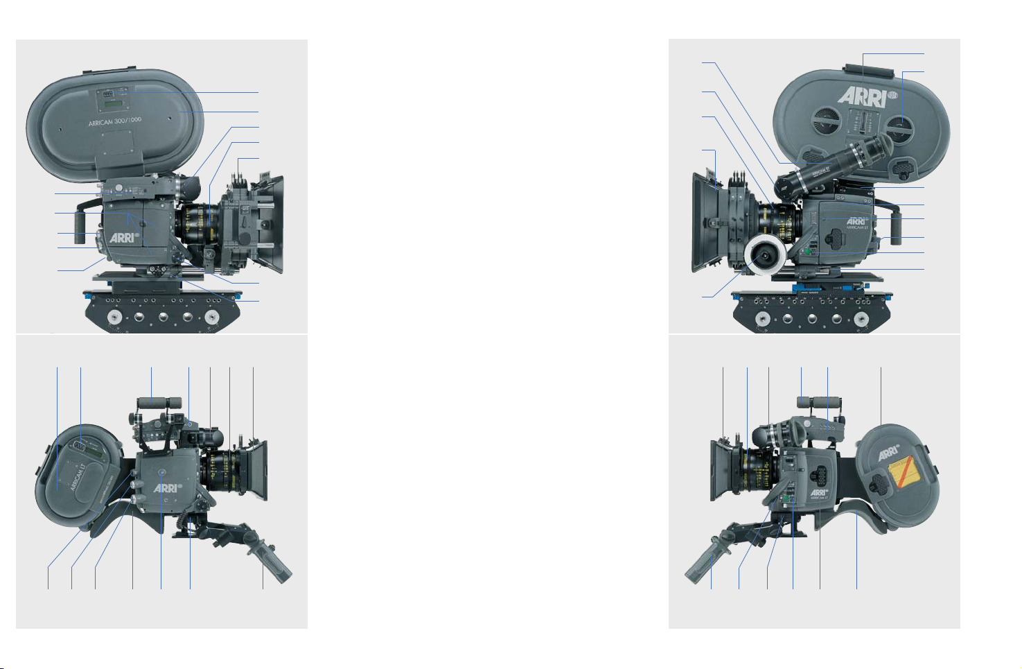
1 CAMERA MAIN SWITCH (ON/OFF)
2 POWER CONNECTOR (24 V)
6
7
8
9
10
5
4
3
2
1
6
24 25 23 9 2226
28
4231
11
21
3027
3 CAMERA ACCESSORY CONNECTOR (CAC)
4 CAMERA ACCESSORY PORT COVERS
5 STUDIO VIDEO ASSIST
6 FOOTAGE COUNTER
7 STUDIO MAGAZINE 300/1000
8 STUDIO VIEWFINDER
9 LDS LENS
10 MATTE BOX (MB 14)
11 ATTACHMENT ROSETTE
12 FOLLOW FOCUS
13 STUDIO MEDIUM EXTENSION
14 MANUAL FOOTAGE INDICATOR
15 TIGHTENING WHEEL
16 TOP LOAD ADAPTER WITH HANDGRIP
17 CAMERA DOOR
18 TAPE MEASURE HOOK
19 STUDIO DOOR FRICTION ADJUSTMENT SCREW
20 CAMERA CONTROL PANEL WITH RUN BUTTON
21 BASE PLATE
22 LIGHTWEIGHT MATTE BOX (LMB 5)
23 LITE VIEWFINDER
24 LITE CARRYING HANDLE
25 LITE VIDEO ASSIST
26 LITE SHOULDER MAGAZINE
27 SHOULDER PAD
28 RISER PLATE (SHOULDER SET)
29 LEFT HANDGRIP
30 RIGHT HANDGRIP WITH RUN BUTTON
13
10
12
8
9
922 24 25 2623
17 2728229
20
14
15
16
17
18
19
20
21
Page 9
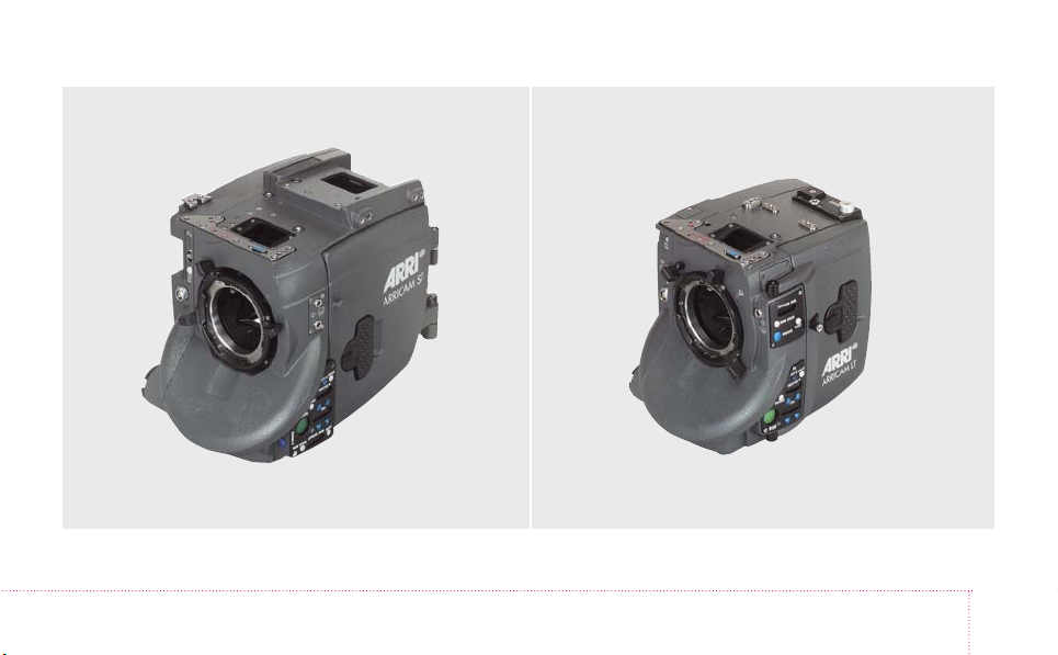
STUDIO LITE
THE ARRICAM CAMERA BODIES
1
Page 10

The Camera Bodies
The cameras’ front
On the front of both cameras, an LDS 54 mm ARRI PL
(positive lock) lens port accepts lenses (spherical or
anamorphic) fitted with either LDS PL or with the well
established regular PL mounts. Depending on the orientation of the lens port, the ARRICAM Cameras will allow
shooting in either Standard 35 or Super 35 format. The
shooting mode is shown by the number 1 (for 35) or 2
(for S35) facing the index.
Notice
It is recommended an ARRICAM Maintenance
Centre or rental house performs the change of format
from 35 to S35 or vice versa. If you must do it yourself, please see the related instructions in chapter
11 – Miscellaneous.
The ARRICAM Cameras are equipped with LDS PL
mounts which differ from the regular PL mounts of the
ARRIFLEX and MOVIECAM cameras in that they are
equipped with electrical contacts that communicate lens
data to the camera. Two sets of LDS contacts are integrated in each lens port to allow the fitting of the lens
according to the needs of the focus puller: The index
lines of the lens can be seen from the top and the bottom or left and the right side of the camera
Notice
Even though there is a difference between the LDS PL
mount and the regular PL mount, all 35mm lenses fitted
with PL mounts can be mounted in the new LDS PL port.
1 – THE CAMERA BODIES
11/2003 ARRICAM System Users’ Guide
17
Page 11
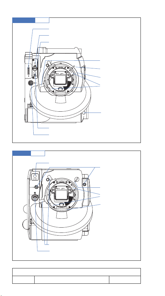
Studio front
Lite front
fig.1/1
fig.1/2
Lens Data Box connector
Beeper
Beeper volume control
DUST CHECK button
24 V dc outlet RS connector
DUST CHECK button
Lens port lever
35/S35 index
Lens port
35/S35 markings
UNLOCK button
(only on extended
control panel)
24 V outlets
heatable eyecup/
work light
35/S35 index
35/S35 markings
Lens port
Lens port levers
24 V dc outlet RS connector
1 – THE CAMERA BODIES
18
11/2003ARRICAM System Users’ Guide
Page 12

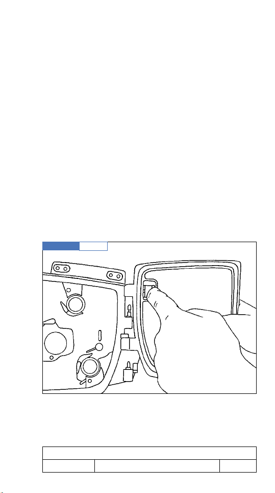
To remove a lens (or lens port cover), rotate the lens port
levers counter-clockwise as far as possible while grasping the lens firmly. Then carefully remove the lens.
To fit a lens, align guide groove in the lens flange with
locating pin in the lens port. Insert the lens flange flat on
the receptacle, making certain the pin engages the lensflange hole easily. Rotate lens lock gently clockwise to
secure until the lens is seated properly. Do not use force!
Notice
1. Especially with heavier lenses, great care must
be taken that the lens is mounted in a straight line
with the port.
2. The LDS Lens must be mounted in the 12 o’clock
or 3 o’clock position to enable the LDS functions.
3. When attaching the lens or lens port cover, take great
care not to harm any elements (e.g. LDS contacts).
4. Heavy and long lenses, such as ZEISS Variable
Prime Lenses or zoom lenses, must be supported
at all times by means of dedicated accessories.
5.
When mounting an LDS Lens, one must be sure
that the contacts and the mount itself are perfectly
clean in order to assure good electricronic communication as well as an even fit of the lens on
the camera port.
Both Studio and Lite
THE DUST CHECK BUTTON
Because the mirror and the movement are driven separately, moving the mirror by means of the inching knob
is not possible. It is also recommended not to move
it manually, there is danger of damage. To check the
gate, either by looking through the lens or by removing it, turn the mirror out of the way by briefly pushing
1 – THE CAMERA BODIES
11/2003 ARRICAM System Users’ Guide
19
Page 13
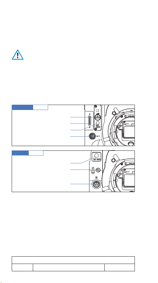
the DUST CHECK button. Even when shooting with a
reduced shutter angle, operating the DUST CHECK button, will open the shutter to 180° and DC will appear
on the FPS display(s).
Caution!
When you need to clean the gate, it is imperative
to turn OFF the camera power first.
After having cleaned the gate, turn the power ON and
briefly push the DUST CHECK button to turn the mirror
into the viewing position – the shutter will return to its
preset angle again automatically.
Studio front
Lite front
fig.1/3
Beeper volume control
Lens Data Box connector
DUST CHECK button
24 V dc outlet RS connector
fig.1/4
DUST CHECK button
24 V dc outlet
Work light/heated eyecup
24 V dc outlet RS connector
On the Studio and Lite
24V OUTLET RS CONNECTOR
To the left of the lens port there is a 24 V outlet marked RS
(
RUN
). This three-pin Fischer connector is protected by a
1.6 A resettable fuse and may be used to remote control
the camera status
RUN
or
STOP
as well as for supply
power to any kind of 24 V accessory, e.g. a zoom drive.
1 – THE CAMERA BODIES
20
11/2003ARRICAM System Users’ Guide
Page 14

Only on the Studio
BEEPER AND BEEPER VOLUME CONTROL
Only the ARRICAM Studio is equipped with a beeper.
Its volume can be increased in three steps by turning
the switch clockwise. The number shown on the switch
will indicate the adjustment: 1=low, 2=medium and
3=loud. When selecting the position 0, the beeper is
OFF
. When the beeper is not turned
briefly when the camera is in
RUN UP
OFF
, it will sound
or
RUN DOWN
status. It will beep intermittently as long as the camera is
RUNNING
in
ASYNC
status.
On the Studio
LDB CONNECTOR
Hidden behind the front right side camera cover (fig.
1/3), a large connector is mounted on the camera
front. When the cover is removed, either a Lens Data
Box Cable Adaptor or the Studio Lens Data Box itself
can be attached to this connector.
On the Lite
24 V HEATED EYECUP/WORK LIGHT OUTLETS
On both sides of the lens port, small connectors supply
the 24 V dc power for the following two accessories:
the Work Light and the Heated Eyecup.
1 – THE CAMERA BODIES
11/2003 ARRICAM System Users’ Guide
21
Page 15
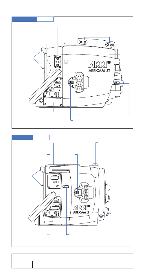
Studio right side
CAC connector
accessory attachments
fig.1/5
Attachments points for
accessory port covers
Lens port
levers
RS connector
for right
handgrip button
Threaded holes
for attaching
the lower cover
or ISB
Power
connector
Lite right side
Main
switch
fig.1/6
Main switch
Magazine
release knob
CAC
connector
Power
connector
1 – THE CAMERA BODIES
22
In-camera Slate
Box connector
Attachment for
Lens Data Box
Right handgrip
rosette attachment
Accessory attachments
Connector for
Lens Data Box
Lens port
levers
RS connector
for right
handgrip button
Attachment rosette
11/2003ARRICAM System Users’ Guide
Page 16
The cameras’ right sides
On the Studio and Lite
RIGHT HANDGRIP ROSETTE ATTACHMENT
The right handgrip is screwed into the threaded socket
in the rosette centre.
On the Studio and Lite
CONNECTOR FOR THE RIGHT HANDGRIP RUN
BUTTON
The 24 V RS connector can either be used to supply 24
V for accessories or to connect a switch for changing
between the
RUN
and
STOP
(i.e.
Standby
) status.
On the Studio and Lite
ACCESSORY ATTACHMENTS
The Carrying Handle or e.g. Universal Low Mode
Bracket is attached to the threaded sockets and gauged
holes on top of the right camera side.
On the Studio and Lite
PROTECTION COVERS
fig.1/7
Covers
➔
➔
➔
➔
➔
Protection covers are components of the ARRICAM System and should be handled with care. When removing
them from the camera bodies, store them immediately in
1 – THE CAMERA BODIES
11/2003 ARRICAM System Users’ Guide
23
Page 17

their cases. When no accessory box or cable adapter
is mounted on the camera, the appropriate protecting
cover must be fitted instead of it to protect the sensitive
connectors!
On the Studio only
RELEASE KNOB OF THE UPPER PROTECTION COVERS
To remove an upper protecting cover, press the release
knob and slide the upper front cover forward or the
upper rear cover backwards. When mounting the protection covers, be sure that they are flush to the camera
before sliding them into the locked position.
Notice
Do not tilt the upper covers during mounting or removing, and do not use force!
By removing the upper front cover the connector for the
Studio Lens Data Box (ST-LDB) will appear.
By removing the upper rear cover the connector for the
Speed Control Box (SCB) will appear.
On the Studio only
RELEASE SCREWS OF THE LOWER COVER
Remove the lower cover for mounting the In-camera
Slate Box (ISB).
On the Lite only
RELEASE SCREW OF THE COVER
To mount the LT-LDB on the Lite, you must first remove the
cover by unscrewing one 3 mm hex screw.
1 – THE CAMERA BODIES
1 – THE CAMERA BODIES
24
24
11/2003ARRICAM System Users’ Guide
01/2003ARRICAM System Users’ Guide
Page 18

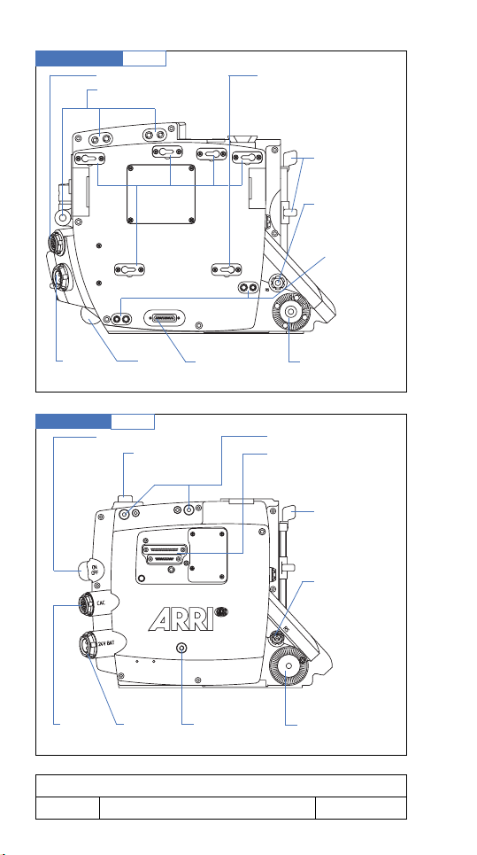
The cameras’ rear
On the Studio and Lite
CAC CONNECTOR FOR ACCESSORIES
The 16-pin Fischer connector, mounted obliquely for
convenience and labelled CAC (camera accessory connector) is the main communication port of the cameras.
Several accessories can be attached there. For further
information see the accessory descriptions and the fig.
1/8 and 1/9 on page 27.
POWER CONNECTOR
The 2-pin Fischer power receptacle, mounted obliquely
for convenience, is used to connect a 24 V battery
or a 24 V dc Power Supply Unit. Further information
about the power supply and power distribution of the
ARRICAM System is described in chapter 10 – Power
Management.
MAIN SWITCH
Protected by two flanges, the MAIN switch will interrupt
the power supply of all electronic components, except
the one of the clock in the In-camera Slate Box – it remains powered to keep the clock working.
SCREWS FOR MAINTENANCE PURPOSES ONLY
On both camera bodies, there are several screws which
are dedicated for maintenance work only. These screws
are marked with a special seal lacquer and/or a safety
label.
1 – THE CAMERA BODIES
1 – THE CAMERA BODIES
01/2003 ARRICAM System Users’ Guide
11/2003 ARRICAM System Users’ Guide
25
25
Page 19

Caution!
Do not touch these screws, otherwise severe damage can occur!
CAMERA OPENINGS
One of the main differences between the two camera
bodies is that you are able to mount Studio Magazines
in one of three different positions (top, back or inclined)
on the Studio by means of the various magazine
adapters while the Lite allows the attachment of the
lightweight Lite Magazines at the rear only. In order to
install Studio Magazines on the Lite, you will have to
use the Studio Magazine to Lite Camera Adapter. Lite
magazines may now be mounted on the Studio, in the
rear position only, by means of the Studio Camera to
Lite Magazine Adapter.
On the Studio only
REAR CAMERA OPENING AND MAGAZINE ADAPTER
ATTACHMENTS
In order to mount one of the four Studio Magazine
Adapters, fit the adapter on the camera body while taking care that the two adjusting pins enter the threaded
holes easily. Then you will have to tighten the six retaining screws firmly – see caution on page 88.
On the Studio only
CONNECTORS FOR THE SCB AND MCB/TSB
These two connectors allow the mounting of the Speed
Control Box (SCB) and the Manual Control Box (MCB)
or Timing Shift Box (TSB) – see chapter 7.
Both connectors must be protected by covers if not used.
1 – THE CAMERA BODIES
26
11/2003ARRICAM System Users’ Guide
Page 20
Notice
To use the Manual Control Box (MCB) or the Timing
Shift Box (TSB) and the Speed Control Box (SCB)
together, you must first mount the SCB and then the
MCB/TSB. To remove the SCB, you will first have to
remove the MCB/TSB from the camera: The MCB/
TSB physically blocks the attachment and removal of
the SCB
Studio rear
Lite rear
fig.1/8
fig.1/9
Threaded holes and connector for the
magazine adapters
Setscrew for maintenance onlyDoor hinge
Release button for magazines/mag.adapter
Camera opening
MCB/TSB connector
SCB connector
Attachements for
magazine adapters
CAC connector
Power connector
Main switch
Electric contacts
for the magazine/
mag.adapter
Main switch
CAC connector
Power connector
Camera opening Rails for the magazines/mag.adapter
1 – THE CAMERA BODIES
11/2003 ARRICAM System Users’ Guide
27
Page 21
The cameras’ left sides
On the Studio and Lite
THE CAMERA DOOR
The door is located on the camera’s left side. To open
the door, push the little spring-lock forwards and lift the
lock latch, then turn the lock latch counter-clockwise.
When closing the door, press it gently towards the camera body and then turn the lock latch clockwise. When
it is closed, the door lock latch must be flush with the
door; the spring-lock keeps the lock in this position.
Notice
When closing the door, be sure that the movement,
the film guides and the buckle switch are placed in
the correct position. When the movement is in its
loading position, the door cannot be closed.
Door Lock
fig.1/10
2.
➦
➡
1.
3.
1 – THE CAMERA BODIES
28
door lock safety
door lock latch
➡
11/2003ARRICAM System Users’ Guide
Page 22
On the Studio and Lite
HOOK FOR TAPE MEASURE
The tape measure can be attached to the hook that indicates the image plane. Further hooks are provided on
several accessories.
On the Studio only
ADJUSTABLE DOOR HINGE AND REMOVABLE DOOR
Should you want to alter the friction of the door use a 2
mm metric hex wrench to adjust the screw at the top of
the lower hinge until the desired friction is set.
To remove the door, loosen this screw fully, then by
pressing and holding the lever, lift the door up clear of
the hinges. When mounting the door on the camera,
take care that the hinge-pins enter the hinges properly.
Studio Door
fig.1/11
2.
➡
1.
➡
1 – THE CAMERA BODIES
11/2003 ARRICAM System Users’ Guide
29
Page 23
Studio left side
Viewfinder
mounting plate
fig.1/12
Connectors 24 V for
heated eyecup
work light
Accessory
attachment
Lens port
levers
Camera control panel
Indication of film plane/
Tape hook
Lite left side
fig.1/13
Upper camera
control panel
Lens port
levers
Lower camera
control panel
Door lock latch
Door lock safety
Viewfinder
mounting plate
Door lock
safety
Indication of film plane/
tape hook
Door
Adjustable
door hinge
Magazine/
adapter release
button
Door
Door
lock
latch
Threaded
hole for
magazine
adapter
1 – THE CAMERA BODIES
30
11/2003ARRICAM System Users’ Guide
Page 24

On the Studio only
CONNECTORS
Power (24 V) for the Heated Eyecup and the Work Light
is supplied via two co-axial connectors.
On the Studio only
ACCESSORY ATTACHMENT
The two threaded sockets and two gauged holes on top
of the camera left side allow mounting of several accessories including a bracket for Steadicam, a similar support system or the modular ARRICAM Carrying Handle
System.
The cameras’ control panels
On both, the Studio and the Lite, most of the functions
are controlled and monitored by means of the Camera
Control Panels. These Panels are located on the camera
left side to be easily accessible and visible for the operator and the focus puller. There are two types of Control
Panel in circulation: The original Standard Camera
Control Panel and the newer Extended Camera Control
Panel. (The Standard may be upgraded to an Extended
through a workshop procedure).
The Studio and the Lite Standard Control Panels are
equipped with FPS push wheel input units. On the
Extended Camera Control Panels, FPS and Shutter opening are set by means of finger operated buttons instead
of recessed ones that require a small poited tool to operate. Furthermore, the Studio Extended Camera Control
Panel has a third display to show the film length.
1 – THE CAMERA BODIES
11/2003 ARRICAM System Users’ Guide
31
Page 25

The Extended Camera Control Panels also allow the
user to select several settings offered in the display
options’ menu.
BASICS
All messages shown on the displays of several components (Camera Body, Accessory Boxes, Video Assists,
Readout Unit, etc.) are generated by computer software
(SW). Together with a firmware (FW), the software is
integrated in the camera bodies and several system
components.
Depending on the type of Camera Control Panel
(Standard or Extended), different indications and messages will be shown on the FPS display. As with other
computer systems, and based on the feedback by
ARRICAM Users, the software and also the firmware will
be updated when necessary. Therefore it is advisable to
know the version of the software and firmware installed
in your camera.
Also when requesting information, the technician will
ask you the software and firmware version number. Last
but not least, is also necessary to be aware that some
messages can be changed without notice when the system is updated. This User’s Guide is updated to cover
the release of version 03E.
Because some messages are exclusively for the
ARRICAM Maintenance Personnel, they are not listed in
this Users’ Guide.
1 – THE CAMERA BODIES
32
11/2003ARRICAM System Users’ Guide
Page 26
OPERATIONS
The Option mode allows the user
• to define the threshold voltage value that must be
reached to initiate the low battery warning.
• to check the software/firmware version installed in
the system components.
Extended Camera Control Panel
fig.1/14
AC
BD
Setting the threshold voltage of the low battery
warning
To set the threshold voltage of the low battery warning,
first turn
OFF
the camera power. Then, enter the Option
mode by holding the BRIGHT button on the Camera
Control Panel (camera left side) pressed and turn
ON
the camera MAIN switch.
Now the following messages will be displayed:
display: shutter FPS Footage
text:
LBat
NiCd
or
User
Nicd
shows that the low battery warning is set to a
default value for Nickel Cadmium batteries. This default
value is set in the factory and cannot be changed by
the users.
If a Lithium Ion or 26.2 volt NiCad battery is used, a different
low battery voltage is needed. To change it, select the
User
mode by pushing the button “C” or “D” – see fig. 1/14 above.
1 – THE CAMERA BODIES
11/2003 ARRICAM System Users’ Guide
33
Page 27

User
When
is displayed, pushing the button “B” will
change the display as follows:
display: shutter FPS Footage
text:
LBat
V21.7
User
By pushing the buttons “C” or “D”, the threshold voltage
can be set anywhere from 20.0 V to 29.9 V.
To save the change of the threshold value in the system,
either push the PHASE button on the Extended Camera Control Panel or switch
OFF
and ON the camera
MAIN switch.
While pushing the PHASE button, the actual voltage of
the power supply will appear on the FPS display.
Checking the software and firmware version installed
in several components
To find out which SW or FW version is actually
installed, first turn
OFF
the camera power, then, enter
the Option mode by holding the BRIGHT button on the
Camera Control Panel pressed (camera left side) and
turn
ON
the camera MAIN switch.
Now the following messages will be displayed:
display: shutter FPS Footage
text:
LBat
NiCd
or
User
By pushing button “B”, the display will change as follows:
display: shutter FPS Footage
text:
1 – THE CAMERA BODIES
34
CLD
V100
SW
11/2003ARRICAM System Users’ Guide
Page 28

This means that the Software Version 100 has been
installed in the Camera Control Panel. (CLD=Camera
Left Display) By pushing either “C” or “D”, the display
will change to a next component or to FW if SW is
already shown.
display: shutter FPS Footage
text:
SCB
FW
104c
Caution!
If a figure (software or firmware version) shown
on the FPS display is blinking, it means that the
installed software/firmware is incompatible with
other software/firmware already installed.
Whenever this happens, push the PHASE button to clear
the warning.
Notice
Only in case of a very serious problem (risk of damaging the camera, risk of wrong film exposure) will
the RUN LED glow red to indicate that the camera is
not ready to shoot. In this case, call your ARRICAM
Maintenance Centre.
Usually, a software/firmware incompatibility will not
affect the system and the camera will stay ready to
shoot. However, the indication of the incompatibility will
appear each time the camera is turned
ON
. This is to
remind you to consult a Maintenance Centre as soon as
you can. When the warning is displayed, basic camera
functions (correct exposure & film handling) will still work
although some accessories may not.
To leave the Option mode, push either the PHASE button or switch the camera MAIN switch
1 – THE CAMERA BODIES
11/2003 ARRICAM System Users’ Guide
OFF
and ON.
35
Page 29

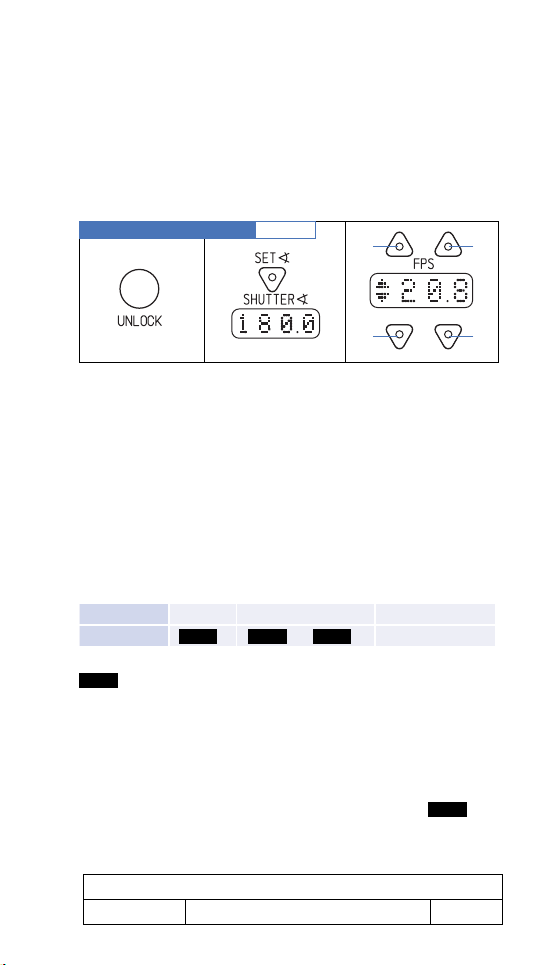
OPERATING THE EXTENDED CAMERA CONTROL
PANEL
In order to set fps or shutter angle on the Extended
Camera Control Panels, hold the unlock button while
pushing the selectors’ buttons. Otherwise
LOCK
will
appear in the related display when a setting button is
pushed.
ACRONYMS
speed control box
SCB
manual control box
MCB
timing shift box
TSB
lens data box
LDB
lens data display
LDD
wireless remote control
WRC
in-camera slate box
ISB
camera control box (ARRIMOTION/Jogbox)
CCB
software
SW
firmware
FW
camera left display (Camera Control Panel)
CLD
RUN BUTTON
Provided that the main power supply is switched
and the camera is
READY
(e.g. film is laced correctly,
power supply is ok), the camera will start to
RUN
ON
when
either the RUN button on the Camera Control Panel or
one of the other RUN buttons, e.g. on the Handgrip,
on the Speed Control Box or on a remote control unit is
pressed. Any of those RUN buttons can be employed
alternately to change the status of the camera
STOP
and vice versa.
1 – THE CAMERA BODIES
36
11/2003ARRICAM System Users’ Guide
RUN
or
Page 30

RUN LED INDICATOR
The RUN LED is off while the camera is in
Standby
or
not powered. When the camera is started, the RUN LED
will glow red while the camera is coming up to speed,
changing to green once the camera is
RUNNING
at
the preset frame rate. When a RUN button is pushed
again to stop the camera, the RUN LED will glow red
while the camera
SLOWS DOWN
camera has stopped
RUNNING
, going out when the
.
Notice
If the RUN LED glows red while the camera is not
RUNNING, it indicates that the camera is NOT
READY. – pushing a RUN button will have no effect.
If the camera is powered, the cause why the camera
is not in Standby status will be displayed on the FPS
displays – see page 44.
FPS SELECTOR
While the camera is
NOT RUNNING
, frame rates
from 1 to 40 (Lite) or 1 to 60 (Studio) can be preset.
If a higher rate is erroneously preset and the RUN button
is pressed, the camera will not start to
display will show
FPS!
.
RUN
and the
Notice
If an SCB is connected to the camera and it’s SPEED
CONTROL switch is set to ON, the FPS selector on the
camera left side is put overridden and either
SCB
will
show on the FPS display of the Standard Camera
Control Panel or the value preset on the SCB will show
on the FPS display of the Extended Camera Control
Panel while the camera is Standby. As soon as the camera is RUNNING, the actual fps rate will be shown.
1 – THE CAMERA BODIES
11/2003 ARRICAM System Users’ Guide
37
Page 31

Studio Standard Camera Control Panel
fig.1/15
RUN LED
PHASE button
Studio Extended Camera Control Panel
UNLOCK button
RUN
button
SHUTTER angle selector
SHUTTER angle display
FPS display
FPS selector
RUN button
fig.1/16
BRIGHT button
SHUTTER angle
selector
PHASE button
SHUTTER angle display
FPS selector
FPS display
RUN LED
RAW STOCK button
1 – THE CAMERA BODIES
38
FPS selector
RESET button
Film length display
11/2003ARRICAM System Users’ Guide
Page 32

Lite Standard Camera Control Panel
RUN LED
fig.1/17
Film length display
RESET button
Battery LED
SHUTTER angle selector
SHUTTER angle display
FPS display
PHASE button
RUN button
Lite Extended Camera Control Panel
fig.1/18
FPS selector
Film length display
RAW STOCK button
RESET button
UNLOCK button
SHUTTER angle
selector
BRIGHT
button
RUN button
PHASE button
SHUTTER angle display
FPS selector
FPS display
RUN LED
FPS selector
1 – THE CAMERA BODIES
11/2003 ARRICAM System Users’ Guide
39
Page 33

One advantage of the Extended Camera Control Panels
is that you can also enter the following preset frame rates:
shown on control panel real setting
6.2 fps 6.25 fps
12.5 fps 12.5 fps
16.6 fps 16.666 fps
23.9 fps 23.976 fps
29.9 fps 29.97 fps
33.3 fps 33.333 fps
All settings are only possible while the camera is not
RUNNING
setting button is pushed while the camera is
RUN
.
will appear in the related display if a
RUNNING
If a component such as the SCB, the MCB or the WRC
has control over the shutter opening, no setting of the
shutter angle is possible by means of the Camera
Control Panel buttons and the controlling device will be
displayed.
SHUTTER ANGLE SELECTOR
While the camera is in
STANDBY
, you may change
the shutter angle either by pushing with a pointed item
– e.g. toothpick – the little selector protected by the Plexiglas cover on the Standard Camera Control Panel or
by pushing the button on the Extended one. As soon as
one is pushed, the shutter advances to the new setting.
The value cycles through the following steps:
11.2° 22.5° 30° 43.2° 45° 60° 75° 86.4°
90° 105° 120° 135° 144° 150° 172.8° 180°
1 – THE CAMERA BODIES
40
11/2003ARRICAM System Users’ Guide
.
Page 34

PHASE BUTTON
Depending on the status of the camera, the PHASE
button allows two different operations.
When the camera is in
STANDBY:
While pressing the PHASE button continuously, the
INCHING
RUN
mode is activated and the movement will
at 1 FPS as long as the button is held down.
When the button is released, the mirror shutter will
automatically park in the viewing position.
While the camera
RUNS
in the
INCHING
mode the
power supply voltage will be displayed in the FPS
display as e.g.
When the camera is
V 24.6
RUNNING:
.
pushing the PHASE button will increase the preset FPS
rate by 0.2 fps as long as the button is held down. This
also works when e.g. the SCB or another remote device
controls the fps rate.
Exceptions:
While the camera is controlled
• by an SCB, the SCB switch is set to SYNC and the
PHASE switch is set to
FIXED
,
• by a Video Assist external synchronization signal.
• by an In-camera Slate Box synchronization signal.
• by an external device and
RAMP
the PHASE button is inactive. When it is
pushed, the FPS display will show
RUNNING
FIXD
a
SPEED
as long as
the button is held pressed.
1 – THE CAMERA BODIES
11/2003 ARRICAM System Users’ Guide
41
Page 35

RAWSTOCK
While the camera is in
STANDBY
press and hold the
RAWSTOCK button to display the film reserve as set by
the magazine.
BAT LED INDICATOR
The bat LED (Lite Standard Camera Control Panel only)
lights up red in case the supply voltage drops below the
threshold value defined in the option mode. The same
indication is provided on the other Camera Control Panels by a warning message on the FPS display.
FPS DISPLAY
Regarding the brightness control of displays
Many components of the ARRICAM System are fitted
with similar displays. The brightness of all these displays
can be adjusted to the needs of the users by means of
the dimmers located e.g. on the Speed Control Box, on
the Manual Control Box or on the Studio Readout. The
adjustment of the display brightness will automatically
affect all components connected to the camera body, so
individual adjustment for each display is not possible.
Regarding the messages shown on the FPS displays
All messages described on the following pages are
generated by the ARRICAM SW Version 3.0E When
requesting information from ARRICAM Maintenance
Technicians, please mention the version of the software
installed on your camera. (see Checking the Software
and Firmware section on page 34)
If another accessory has control over the camera the
Extended Camera Control Panel shows what speed the
1 – THE CAMERA BODIES
42
11/2003ARRICAM System Users’ Guide
Page 36

camera will run on its FPS display. At the same time, the
controlling component is shown e.g on the Studio Readout. As soon as you attempt to change the FPS value on
the Extended Camera Control Panel, its FPS display will
show the component which actually controls the camera
(e.g. MCB, SCB, WRC) – no changes will be possible
there.
The four digit display marked FPS will not only show
the actual frame rate while the camera is
RUNNING
,
but will also serve as an important central information
display. Warning messages will alternate with the fps
values. If there is more than one warning message, they
will alternate at a two seconds frequency.
When there is no reason for displaying warning messages, the FPS displays will inform about the following status.
Notice
As soon as the camera detects that the software of
any of the system components (e.g. Lens Data Box,
Video Assist) is incompatible, the warning
SW
will
appear on the FPS displays and the camera will go
to NOT READY. Simultaneously,
the SHUTTER displays. By pushing one of the
Phse
will appear on
PHASE
buttons, the warnings will disappear and the camera
goes to Standby. The warnings will appear automatically when the camera is powered ON in order to
remind you to ask an ARRICAM Maintenance Centre
to up-date the system as soon as possible.
1 – THE CAMERA BODIES
11/2003 ARRICAM System Users’ Guide
43
Page 37

MESSAGE
Explanation of the message, glows
MESSAGE
)
Explanation of the message,
(
glows alternately with an other message
MESSAGE
(
(
‹‹
)
)
MESSAGE
››
STANDBY
NOT READY
RUNNING
REMARK
Explanation of the message, blinks
Explanation of the message, blinks fast
The indicated status informs why the
camera is e.g. not ready or which component has control over the camera.
LIST OF MESSAGES AND WARNINGS on the FPS display
(Software Version 3.0E)
FPS DISPLAY
Camera is not powered.
....
Electronic problem.
REMARK An electronic problem occurs that can only
be fixed by Maintenance Technicians.
running point
REMARK An electronic problem occurs that can only
Electronic problem.
be fixed by Maintenance Technicians.
0.0
Camera is not
STANDBY Camera is ready to shoot with the preset fps
RUNNING
.
shown on the FPS selector (Standard Camera
Control Panel) or displayed (Extended Camera
Control Panel).
24.0
Camera is
RUNNING Camera is
RUNNING
RUNNING
.
with the preset fps
(e.g. 24 fps).
1 – THE CAMERA BODIES
44
11/2003ARRICAM System Users’ Guide
Page 38

-12.0
Camera is
RUNNING The camera is
RUNNING REVERSE
RUNNING REVERSE
FPS DISPLAY
.
with the
preset fps (e.g. 12 fps).
Asy
Asynchronity.
RUNNING Camera
RUNS
at another fps than the pre-
set rate.
Bat
(
(
NOT READY The power source does not supply the
)
)
Battery low.
requested voltage.
RUNNING If the camera cannot reach the preset fps
rate,
Bat
and the current fps rate will alternatively light up on the display.
See more – chapter 10, page 363.
Bukl
(
(
NOT READY At least one of the buckle trip switches has
)
)
Buckle trip.
been tripped.
CAL
(
)
Lens calibration in progress
STANDBY
CAL
alternates with
FPS
or further warning
message.
RUNNING
CAL
alternates with
FPS
or further warning
message.
CCB
Camera Control Box.
STANDBY The ARRIMOTION CCB controls the cam-
era.
–CCB
Camera Control Box.
STANDBY The ARRIMOTION CCB controls the camera
for shooting
1 – THE CAMERA BODIES
11/2003 ARRICAM System Users’ Guide
REVERSE
.
45
Page 39

Covr
(
)
Dual Port Adapter Cover is missing.
FPS DISPLAY
While a magazine is mounted on the Dual
Port Adapter, the remaining adapter opening is not light tight because the Dual Port
Adapter special Aluminium Cover is missing.
STANDBY ATTENTION: camera remains in Standby even
if the Dual Port Adapter Cover is missing!
Covr
alternates with
FPS
or further
warning messages.
RUNNING ATTENTION: camera can
RUN
even when
the Dual Port Adapter Cover is missing!
Covr
alternates with
FPS
or further
warning messages.
DC
(
(
NOT READY The DUST CHECK or PHASE button has
(
)
)
Dust check.
been pushed while the camera is
BY
.
Door
)
Lite Magazine to Studio Camera Adapter
STAND
door is not closed.
RUN.
Door
Door
alternates
alternates
STANDBY Camera remains in Standby.
RUNNING Camera continues to
with
with
FPS
or further warning messages.
FPS
or further warning messages.
End
Film end warning.
STANDBY Less than 6 m/20 ft unexposed film remain
in the magazine.
0.0
.
RUNNING Less than 6 m/20 ft unexposed film remain
in the magazine.
actual fps e.g.:
1 – THE CAMERA BODIES
46
End
will alternate with
End
will alternate with
24.0
.
11/2003ARRICAM System Users’ Guide
Page 40

FPS DISPLAY
Fixd
No manual phase.
RUNNING The PHASE button has been pushed while
the SPEED CONTROL switch on the SCB is
set on SYNC mode and the PHASE switch
has been set to FIXED.
FPS!
(
(
STAND BY An fps rate below or above the fps range of
)
)
Wrong preset fps.
the camera has been preset.
!FW!
(
(
STANDBY Firmware incompatibility.
NOT READY Camera is not ready to shoot.
(
STANDBY Software incompatibility.
NOT READY Camera is
(
NOT READY Camera is not ready.
RUNNING The camera stops
REMARK This message will only be displayed on the
)
)
Firmware updating.
!SW!
(
)
)
Software updating.
NOT READY
Hbat
(
)
)
The power supply voltage is too high.
era components will be shut
.
RUNNING
and all cam-
OFF
.
FPS display on the Camera Control Panel.
Heat
Camera Heater is ON.
STANDBY The shutter value will alternate with
to show that the Heater is
NOT READY Camera remains in
RUNNING By pushing the RUN button, the camera
should start to
RUN
ON
Standby
.
. If not, the camera is
Heat
.
.
not warm enough to ensure correct running.
While the camera is
era
Heater turns itself
RUN
NING, the Cam-
OFF
.
1 – THE CAMERA BODIES
11/2003 ARRICAM System Users’ Guide
47
Page 41

FPS DISPLAY
Jam
(
(
NOT READY At least one sprocket guide is open or a film
)
)
Guides, jam.
jam has occurred.
Mag
(
(
)
)
There is a problem with the magazine or
magazine adapter.
NOT READY Camera is not ready.
MCB
Manual Control Box controls camera.
STANDBY An MCB has control over the camera.
-MCB
Manual Control Box controls camera.
STANDBY An MCB has control over the camera and
the
REVERSE
shooting mode has been
selected on the SCB.
m/ft
(
)
A magazine with a unit of measurement
different to its predecessor has been mounted.
STANDBY
m/ft
alternates with
FPS
or further warning
messages. Acknowledge by pressing PHASE
or change the unit of measurement.
Movm
Movement open.
NOT READY The movement block is not in the fully closed
position.
M/S!
(
(
RUNNING The mirror shutter and the movement have
)
)
Movement/shutter async.
lost synchronization.
MTmp
(
(
)
)
Movement motor has overheated due to
overload.
STANDBY The camera goes into NOT READY Wait for
motor to cool down.
1 – THE CAMERA BODIES
48
11/2003ARRICAM System Users’ Guide
Page 42

FPS DISPLAY
Out
(
(
NOT READY Shows that no film is left.
RUNNING The camera stops and goes to
)
)
Stock out.
NOT READY
the RUN LED will glow red.
REMARK To reset, take the magazine off.
RAMP
(
)
Ramping problem.
NOT READY Alternates with FPS or messages like SCB,
WRC, etc.
Check ramp values, at least, one of the
settings is out of the possible range.
Rev!
(
(
STANDBY When REV is selected while an LT Mag.
STANDBY An SCB has control over the camera.
STANDBY An SCB has control over the camera and
)
)
REVERSE RUN
is used,
SCB
Speed Control Box controls camera.
– SCB
Speed Control Box controls camera.
the
REVERSE
not possible.
Rev!
will show the incompatibility.
shooting mode has been
selected.
Spd!
(
(
RUNNING The camera stops and goes into NOT READY.
)
)
The camera has exceeded its speed limit.
Pressing the PHASE button resets the warning.
SW
(
(
NOT READY Appears simultaneously with
)
)
Software incompatibility.
on the SHUTTER display.
1 – THE CAMERA BODIES
11/2003 ARRICAM System Users’ Guide
Phse
warning
49
Page 43

FPS DISPLAY
Syn
(
)
Synchronization.
STANDBY SCB controls the camera to
RUN FWD
(forward) and the SPEED CONTROL switch
is set to SYNC but no valid sync signal is
present.
RUNNING Camera changes to
ATTENTION: Alternates with actual fps even
NOT READY
.
though the synchronization fails!
–Syn
(
)
Synchronization.
STANDBY SCB controls the camera to
RUN REVERSE
and the SPEED CONTROL switch is set to
SYNC but no valid sync signal is present.
RUNNING Camera changes to
ATTENTION: Alternates with actual fps even
NOT READY
.
though the synchronization fails!
TcSy
(
)
Synchronization.
STANDBY The In-camera Slate Box is set in SYNC
mode but there is no valid input signal
present.
RUNNING Camera changes to NOT READY.
ATTENTION: Alternates with actual fps even
though the synchronization fails!
REMARK No REV filming is possible when
TcS y
is displayed.
Time
(
(
)
)
The camera has timed out after 350m of
continuous running to prevent it running
indefinitely.
STANDBY Camera is
NOT READY
. This can be
cleared by pressing the PHASE button.
RUNNING The camera stops and goes into NOT
READY.
1 – THE CAMERA BODIES
50
11/2003ARRICAM System Users’ Guide
Page 44

FPS DISPLAY
TkUp
(
(
)
)
The take up side of the magazine has no
tension.
NOT READY Camera is
RUNNING The magazine feed side has tension but the
take up side
NOT READY
RUNS
.
free. Most likely the film
has not been attached correctly to the take
up core. Reload the magazine.
Updt
Software updating.
STANDBY Software update in progress.
NOT READY Camera is
V 24.6
Camera is
NOT READY Camera is
RUNNING While the PHASE button on the Camera
NOT READY
INCHING
.
NOT READY
.
.
Control Panel is pressed down, the camera
is
INCHING
and the actual voltage
(e.g. 24.6 V dc) is displayed.
V 3.3
In-camera Slate Box power management.
The ISB battery voltage (e.g. 3.3 V) will
appear while the TEST button on the
In-Camera Slate Box is pushed.
ViSy
(
)
Synchronization.
STANDBY The Video Assist IVS controls the synchroni
zation of the camera but there is no valid
input signal present.
RUNNING Camera changes to NOT READY.
ATTENTION: Alternates with actual fps even
though the synchronization fails!
REMARK No REV filming is possible when
ViSy
is
displayed
1 – THE CAMERA BODIES
11/2003 ARRICAM System Users’ Guide
51
Page 45

FPS DISPLAY
Wind
Magazine is taking up loose film.
NOT READY Camera is
RUNNING Either there is no film in the magazine, the
NOT READY
.
whole exposed film is still in the magazine
or, most likely, the film head has come out
of the take up core. Reload the magazine.
REMARK If an empty magazine is mounted on the
camera,
camera is powered – the camera is
READY
Wind
appears as soon as the
NOT
. The message will fade out after
about 25 sec. with a 120/400 Mag. or
about 35 sec. with a 300/1000 Mag.
Notice
Only when
Wind
fades out, you will be able to
start the camera.
Caution!
Do not turn the camera ON when a loaded
magazine is mounted but the film is not threaded.
For testing purposes without film, either remove the
loaded magazine or mount an empty magazine
on the camera.
WRC
WRC controls the camera.
STANDBY A Wireless Remote Control has control over
the camera.
– WRC
WRC controls the camera.
STANDBY A Wireless Remote Control has control over
the camera and the
REVERSE
shooting mode
has been selected.
1 – THE CAMERA BODIES
52
11/2003ARRICAM System Users’ Guide
Page 46

FURTHER MESSAGES ARE ONLY DISPLAYED ON THE
EXTENDED CAMERA CONTROL PANELS
FPS DISPLAY/EXTENDED CAMERA CONTROL PANEL ONLY
CCB
‹‹
STANDBY No fps adjustment is possible on the Cam-
››
CCB controls the camera.
era Control Panel because ARRIMOTION
CCB/Jogbox controls the camera.
– CCB
‹‹
STANDBY No
››
CCB controls the camera.
REVERSE
fps adjustment is possible
because ARRIMOTION CCB/Jogbox
controls the camera.
LOCK
Camera Control Panel is locked.
STANDBY Press the UNLOCK button to adjust the fps.
MCB
‹‹
STANDBY No fps adjustment is possible on the Cam-
››
MCB controls the camera.
era Control Panel because MCB controls
the camera.
– MCB
‹‹
STANDBY No
››
MCB controls the camera.
REVERSE
fps adjustment is possible
because MCB controls the camera.
RUN
Camera is
RUNNING No fps adjustment is possible while the cam-
era is
RUNNING
RUNNING
.
.
SCB
‹‹
STANDBY No fps adjustment is possible on the Panel
››
SCB controls the camera.
because SCB controls the camera.
– SCB
‹‹
STANDBY No fps adjustment is possible because SCB
››
SCB controls the camera.
controls the camera.
1 – THE CAMERA BODIES
11/2003 ARRICAM System Users’ Guide
53
Page 47

FPS DISPLAY/EXTENDED CAMERA CONTROL PANEL ONLY
Syn
‹‹
STANDBY No adjustment of the fps is possible
››
SCB is in
SYNC
mode.
because the Speed Control Box SCB controls the camera to
RUN FORWARD
and the
SPEED CONTROL switch is set to SYNC.
– Syn
‹‹
STANDBY No adjustment of the fps is possible
››
SCB is in
SYNC
mode.
because the Speed Control Box SCB controls the camera to
RUN REVERSE
and the
SPEED CONTROL switch is set to SYNC.
TcSy
‹‹
STANDBY No adjustment of the fps is possible
››
ISB is active and SCB is in
SYNC
mode.
because the In-camera Slate Box ISB controls the camera and the SPEED CONTROL
switch is set to SYNC.
ViSy
‹‹
STANDBY No adjustment of the fps is possible
››
IVS controls the camera.
because Video Assist IVS controls the camera.
WRC
‹‹
STANDBY No fps adjustment is possible on the Cam-
››
WRC controls the camera.
era Control Panel because WRC controls
the camera.
– WRC
‹‹
STANDBY No
››
WRC controls the camera.
REVERSE
the SCB because WRC controls the camera.
1 – THE CAMERA BODIES
54
fps adjustment is possible on
11/2003ARRICAM System Users’ Guide
Page 48

LIST OF MESSAGES AND WARNINGS ON THE
SHUTTER DISPLAY (Software Version 3.0E)
As long as the camera is
Standby
and the SHUTTER SET
SHUTTER DISPLAY
button is pushed, the display will show the preset value.
While the camera is
RUNNING
, the SHUTTER display
will automatically show the actual shutter opening
angle.
Beside this, the SHUTTER display is also used to show
further information.
ISB0
Shutter closed.
RUNNING The In-camera Slate System is
era
RUNS UP
or
DOWN
ON
, the cam-
, and the mirror
shutter is set to 0 degrees.
CCB
(
(
STANDBY No shutter adjustment is possible on the
)
)
CCB controls the camera.
Camera Control Panel because ARRIMOTION CCB controls the camera.
Err
(
(
STANDBY Shutter error. The actual shutter angle does
)
)
Shutter problem.
not equal the preset shutter setting.
NOT READY When a shutter error occurs, the camera
stops and changes to
NOT READY
.
Lock
Camera Control Panel is locked.
STANDBY Press UNLOCK button to change the shutter
setting.
MCB
(
(
STANDBY No shutter adjustment is possible on the
)
)
MCB controls the camera.
Camera Control Panel because MCB controls the camera.
1 – THE CAMERA BODIES
11/2003 ARRICAM System Users’ Guide
55
Page 49

SHUTTER DISPLAY
Run
(
(
RUNNING The shutter adjustment is not possible while
(
STANDBY No shutter adjustment is possible on the
)
)
Camera is
the camera is
SCB
(
)
)
SCB controls the camera.
RUNNING
RUNNING
.
.
Camera Control Panel because SCB controls the camera.
TSB
(
)
The Timing Shift Box TSB is operational.
STANDBY Alternates with shutter angle.
RUNNING Alternates with shutter angle.
WRC
(
(
STANDBY No shutter adjustment is possible on the
)
)
WRC controls the camera.
Camera Control Panel because WRC controls the camera.
REMARK: The following message will not be displayed
on the Extended Camera Control Panel.
MCB
(
)
Shutter selector is pushed while the Manual
Control Box MCB switch is set to control the
shutter.
STANDBY Alternates with shutter angle.
RUNNING Alternates with shutter angle.
Phse
(
(
NOT READY Appears simultaneously with the
)
)
Software incompatibility.
SW
warning in the FPS display.
REMARK: By pushing one of the PHASE buttons the
camera goes in
1 – THE CAMERA BODIES
56
STAND BY
status.
11/2003ARRICAM System Users’ Guide
Page 50

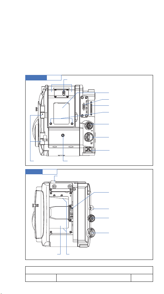
The cameras’ top
On Studio & Lite
EXCHANGEABLE ENGRAVED VIEWFINDER
MOUNTING PLATE
The engraved Viewfinder Mounting Plate shows the format the camera has been set to – either STANDARD 35
or SUPER 35 format – see fig. 1/19.
Notice
The adjustment should be done by trained personnel
of ARRICAM Maintenance Centres or rental houses.
If, for some reason, you have to change the format of
the camera, please see the description of the
procedure in chapter 11 – Miscellaneous.
When attaching a viewfinder, carefully line up the pins
on the base of the viewfinder with the holes on the
Viewfinder Mounting Plate. Be sure that both plugs connect easily.
Viewfinder Mounting Plate
fig.1/19
Viewfinder attachments
(threaded holes)
Format label
Viewfinder attachments
(gauged holes)
On Studio & Lite
ADJUSTING SCREWS
Caution!
Do not touch the adjusting screws – they must
be used by technicians of the ARRICAM Maintenance Centres only!
1 – THE CAMERA BODIES
11/2003 ARRICAM System Users’ Guide
57
Page 51

Studio top
Viewfinder
connector
Viewfinder
window
Tape
hook
fig.1/20
Lens cap
Viewfinder
mounting plate
Dovetail bracket
for accessories
Magazine adapter
attachment
Adjustable
door hinge
fig.1/21
Lite top
Viewfinder
connector
Door
hinge
Tape
hook
Viewfinder
window
Release knob for magazines/adapter
1 – THE CAMERA BODIES
58
CAC connector
Connector for the
magazine adapters
Lens cap
Viewfinder
mounting plate
Attachment for
accessories
11/2003ARRICAM System Users’ Guide
Page 52

On the Studio only
MAGAZINE ADAPTER ATTACHEMENT
The magazine adapters are fixed to the Studio body by
six screws. Firmly screw them into the threaded sockets
on the camera top.
Notice
The two screws in the middle of the adapter should
be tightened first! (As indicated on the adapter.)
On the Studio only
CONNECTOR FOR THE MAGAZINE ADAPTERS
This connector provides communication between the
magazines and the Studio.
On the Lite only
FIXTURE FOR CARRYING HANDLE AND UNIVERSAL
LOW MODE SET
Several fixtures are provided for mounting either Carrying Handles or the Universal Low Mode Set or similar
support system. For mounting instruction see chapter 9
– Camera Supports.
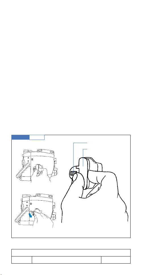
RELEASE-KNOB FOR MAGAZINE UNLOCKING
To remove a camera opening cover, an Lite Magazine or either of the Lite Magazine Adapters, push the
RELEASE knob and, while holding it pressed down, carefully pull the magazine sideways out of the Lite body.
Caution!
Do not touch the adjusting screws!
1 – THE CAMERA BODIES
11/2003 ARRICAM System Users’ Guide
59
Page 53

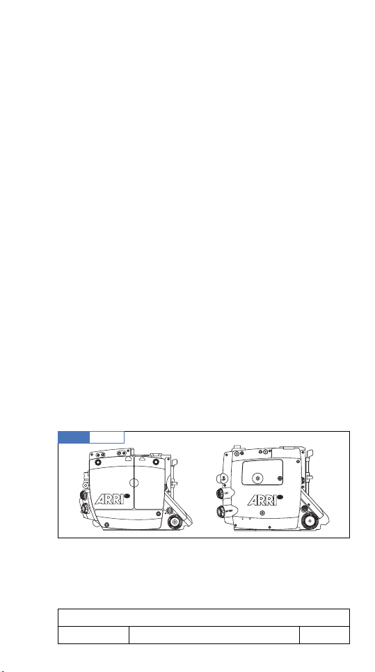
The camera bodies’ bases
When mounting the camera on a head or a Baseplate,
be sure that both plates, the gauged holes and the
threaded sockets are clean. When using the Power
Bridgeplate, slide the cover on the base of the cameraback to allow the supply of power to the contacts
provided on the plate.
Caution!
Before fixing the camera, please check that the
3/8” tightening screws will not penetrate the
camera base more than 0.27” or 7 mm.
Both camera bases are similar.
Caution!
Any screws not previously described are strictly
reserved for Maintenance Technicians only! Do
not touch any of these adjusting screws!
Studio base
Threaded
holes
fig.1/22
Gauged holes
Lite base
Sliding cover of the
power connectors
1 – THE CAMERA BODIES
60
Attachment for
shoulder pad
11/2003ARRICAM System Users’ Guide
Page 54

The camera bodies’ interiors
Despite the different sizes of the cameras’ interiors, both
cameras are equipped with similar components.
THE MOVEMENT
Either a 4 or 3 perforation pull-down movement can be
installed in both camera bodies by trained Maintenance
Technicians. Both movements are fitted with similar
operational items. By turning the movement locking lever
clockwise, the movement will slide back into the loading position. By turning the lever counter-clockwise, the
movement block will slide forwards to the Aperture Plate
and finally lock in place.
Caution!
• Before sliding the movement to the loading
position, turn the INCHING knob until the index
is in the LOOP position.
• In order to secure the movement in its shooting
position, push the lever counter-clockwise to
overcome a mechanical resistance with a click,
which will hold the movement firmly in this front
shooting position.
Movement
adjustment screw
1 – THE CAMERA BODIES
11/2003 ARRICAM System Users’ Guide
fig.1/23
Spacer plate
Movement
Front film guide
Spacer plate handle
Spacer plate safety spring
Movement
locking lever
Inching knob
Pitch
adjustment screw
61
Page 55

fig.1/24
Lite Interior
Upper loop marking
Upper buckle trip
Upper film guide releasing knob
Upper film guide
Rrear buckle trip
Lower film guide
Lower buckle trip
Lower loop marking
Lower film guide releasing knob
Upper sprocket/loop adjustment sprocket roller
Aperture plate locking lever (see fig. 1/25 and 1/28)
Studio Interior
1 – THE CAMERA BODIES
62
Lower sprocket/loop adjustment sprocket roller
11/2003ARRICAM System Users’ Guide
Page 56

THE PITCH ADJUSTMENT SCREW
In order to adjust the movement to the properties and
dimensions of the film material in use, and at the same
time achieve the quietest and most gentle film transport,
the pitch can be controlled. The PITCH Adjustment
screw has marks and buffer stops; the adjusting range is
a narrow segment of a screw turn. While the camera is
running at the normal frame rate (24 or 25 fps), slowly
turn the PITCH Adjustment screw with a 3 mm metric
hex wrench back and forth until the noise level reaches
its minimum. In this position, the camera
RUNS
smoothly
and quitely. This PITCH Adjustment should be repeated
whenever the raw stock type is changed.
THE MOVEMENT ADJUSTMENT SCREW (FW/REV)
Because some Black & White films have unusual
mechanical properties, it is recommended to set the
movement to REV, in order to obtain the optimum steadiness when shooting in
REVERSE
with these materials.
To do so, turn the screw with a 3 mm metric hex
wrench.
THE INCHING KNOB
The large knurled knob allows manual
INCHING
of the
camera. Be aware that turning this INCHING knob will
only move the pull-down claws and register pins but not
move the shutter. While the camera is powered, the film
in the magazine is tensioned automatically. If you want
to prevent this, e.g. when threading the camera, first
move one of the buckle trips out of its rest position.
1 – THE CAMERA BODIES
11/2003 ARRICAM System Users’ Guide
63
Page 57

THE APERTURE PLATE
These Aperture Plates are made of extremely hard material; the film touches the Plate only in the perforation
area. The openings for the registration pins are located
left and right of the gate. A side guide rail is attached
to the Aperture Plate right side. Clean the Aperture Plate
carefully and regularly. Only when it is badly smudged
– which will rarely be the case when handled meticulously – you should clean it very carefully with a small
brush or a toothpick.
Caution!
Never lubricate the Aperture Plate!
The film gate with the Aperture Format Mask and Filter
Holder is integrated in the Aperture Plate. A set with
several Aperture Format Masks is available. If it is
intended to shoot with open gate, it is recommended
to use the Universal Aperture Format Mask in order to
avoid the risk of image overlapping and flare.
Aperture Plate
fig.1/25
Gate
1 – THE CAMERA BODIES
64
in-camera
slate window
11/2003ARRICAM System Users’ Guide
Page 58

UNIVERSAL (open gate)
1 : 1.33 Full aperture (ANSI)
1 : 1.375 Academy
1 : 1.66
1 : 1.85
1 : 2.35
S35 / 1 : 1.78
S35 / 1 : 1.85 (ANSI)
S35 / 1 : 1.85 (Asymmetric)
S35 / 1 : 2.35 (ANSI)
MOUNTING AND REMOVING THE APERTURE PLATE
In order to check the gate, to exchange a Aperture
Format Mask or a filter, the Aperture Plate must be
removed from the camera body.
To extract the Aperture Plate:
1. turn the camera MAIN switch
OFF
2. turn the INCHING knob until its marking matches the
LOOP index
3. swing the movement locking lever clockwise until the
movement reaches its rear position
4. lift the Aperture Plate locking lever while holding the
black handle of the Aperture Format Mask in order to
avoid that the Aperture Plate hits the movement block
5. take hold of the Aperture Plate by the Aperture Format
Mask handle, lift it and extract the Aperture Plate.
Caution!
• The surfaces where the Aperture Plate meets the
camera body must be meticulously clean – any
dirt might alter the flange focal distance.
• In case the Aperture Plate is slanting, start inserting again.
1 – THE CAMERA BODIES
11/2003 ARRICAM System Users’ Guide
65
Page 59

Studio Interior
Aperture plate
locking lever
fig.1/26
To insert the Aperture Plate:
While holding the Aperture Format Mask handle, insert
the Aperture Plate on the mouting rail. Gently press it forward while lifting the spring loaded Aperture Plate locking lever. As soon as it is in place, bring the lever back
to its resting position (=lock) again. You can only insert
the Aperture Plate parallel to the shaft!
Notice
For mounting, the Aperture Plate has a V-shaped
notch at its bottom edge. This notch must be absolutely clean to make sure the Aperture Plate can be
seated properly.
1 – THE CAMERA BODIES
66
11/2003ARRICAM System Users’ Guide
Page 60

Studio Interior
fig.1/27
Aperture plate
v-shaped notch
Caution!
When inserting the Aperture Plate in the camera,
be sure that the locking lever completely returns fully.
The correct resting position is flush with the Plate.
THE APERTURE FORMAT MASKS AND FILTER HOLDER
Caution!
• An Aperture Format Mask and a Filter Holder
must always be inserted in the Aperture Plate.
• The Aperture Plate can only be locked if the
Filter Holder and the Aperture Format Mask are
correctly inserted.
1 – THE CAMERA BODIES
11/2003 ARRICAM System Users’ Guide
67
Page 61

To remove a Aperture Format Mask or a Filter Holder:
1. remove the Aperture Plate from the camera body
2. pull the Filter Holder sideways out of the Aperture
Plate
3. press the Aperture Format Mask lightly on its side flap
towards the film gate and then pull it out sideways
To insert a Aperture Format Mask or a Filter Holder:
1. check that the Aperture Plate and the contact surface
are absolutely clean
2. push the new Aperture Format Mask sideways into
the Aperture Plate
3. check that the film gate is perfectly clean
4. insert (or preferably not) a gelatine filter into the
Holder and cut it appropriately
5. check meticulously if the filter is free of imperfection,
dust, dirt, fingerprint, etc.
6. push the Filter Holder behind the Aperture Format
Mask into the Aperture Plate
7. insert the Aperture Plate into the camera body.
Aperture Plate
1 – THE CAMERA BODIES
68
fig.1/28
Filter holder
Aperture
Format Mask
11/2003ARRICAM System Users’ Guide
Page 62

Notice
• Sliding the movement block forwards when the
Aperture Plate is not correctly in place can cause
damage to the camera!
• The presence of a filter in the film gate will be
shown on the Lens Data Display and on the System
Line on the video monitor.
Caution!
• Be careful not to damage Aperture Plate or gate
– this might have serious consequences!
• Unless absolutely necessary, avoid placing a
gelatine filter in the film gate. Even a microscopic air bubble or speck of dirt will be seen
extremely enlarged on the screen.
• If there is no other alternative and you have to
use a filter in the gate, do not forget to clearly
mark the type of filter inserted in the camera.
THE IN-CAMERA SLATE WINDOW
The Aperture Plate has two slots for the pull-down claws
and a round window that allows the exposing of the
In-camera Slate on the film. The slots as well as the
surface of the Aperture Plate and the little window must
always be clean – check regularly.
THE SPACER PLATE
In the centre of the front film guide, there is an opening
for the Spacer Plate. This Plate – held firmly in place
by magnets – has raised surfaces that hold the film
in the gate plane. Smudged surfaces may cause film
scratches!
1 – THE CAMERA BODIES
11/2003 ARRICAM System Users’ Guide
69
Page 63

To clean the Spacer Plate, it must be removed first
1. slide the movement to its rear position.
2. press the safety spring fixture downwards, at the
same time press the Spacer Plate backwards by its
handle.
3. remove the Spacer Plate by pulling it upwards
4. check Spacer Plate thoroughly and – if necessary –
clean it with lint-free cloth or a toothpick. Also clean
the rear of the Spacer Plate.
Caution!
While manipulating the Spacer Plate, great care
must be taken not to touch the Aperture Plate and
the gate with the Spacer Plate. If you take the
Spacer Plate out of the camera, it is paramount
to slide the movement to its rear position before
removing or inserting the Plate.
To install the Spacer Plate
1. take hold of the Spacer Plate by its handle and insert
it at an angle from above into the movement block.
2. push the Spacer Plate downwards until it locks
audibly in place.
Spacer Plate
1 – THE CAMERA BODIES
70
fig.1/29
11/2003ARRICAM System Users’ Guide
Page 64

THE MAGAZINES AND MAGAZINE ADAPTERS
2
Page 65

The Four ARRICAM Magazines
Convention: In the following description, the cover is
considered being the magazine front. So a mounted
magazine will have the latches on the camera left side.
All ARRICAM Magazines are built to ensure the
smoothest and quietest operation possible. Therefore
high-end electronics and mechanical components have
been assembled in rugged but lightweight shells. Due to
the characteristics of the material used and the special
treatment of the surfaces, temperatures up to 40° C/
104° F will not affect proper operation of the ARRICAM
Equipment. If the ambient temperature drops below -10°
C/-14° F, thermostatically controlled heaters will automatically ensure an adequate temperature in the cameras and the Studio Magazines. In case of heavy frost, a
Heated Barney will help. Motors, heater and digital footage counter are located at the rear of the magazines.
The roller assemblies contain three or four rollers. Roller
bearings should be serviced at an ARRICAM Maintenance Centres only. The roller assembly is best cleaned
with a small vacuum cleaner.
The ARRICAM System includes four application specific
magazines.
1. Studio Magazine 300/1000 for Studio and Lite
2. Studio Magazine 120/400 for Studio and Lite
3. Lite Shoulder Magazine for Lite and Studio
4. Lite Steadicam Magazine for Lite and Studio
Caution!
No other ARRI or MOVIECAM Magazine can be
used with the ARRICAM Cameras.
2 – THE MAGAZINES AND MAGAZINE ADAPTERS
11/2003 ARRICAM System Users’ Guide
73
Page 66

Studio Magazine 300/1000
fig.2/1
Studio Magazine 120/400
Lite Shoulder Magazine
Lite Steadicam Magazine
fig.2/2
fig.2/3
fig.2/4
2 – THE MAGAZINES AND MAGAZINE ADAPTERS
74
11/2003ARRICAM System Users’ Guide
Page 67

The two main differences between the Studio and Lite
Magazines are that only the Studio Magazines allow filming in REVERSE mode and they are equipped with heaters.
Both Studio Magazines allow FORWARD filming from 1
to 40 fps on the Lite and from 1 to 60 fps with the
Studio. With both cameras, the Studio Magazines
allow shooting REVERSE from 1 to 32 fps.
Notice
• When using the Studio with a Steadicam, no
special magazine is needed because of the
orientation of the Back Load Adapter.
• To mount Studio Magazines on the Studio, one of
the three magazine adapters is necessary – see
fig. 2/15 and 2/16 on page 86.
• To use Studio Magazines on the Lite, the Studio
Mag to Lite Camera Adapter must be used – see
fig. 2/28 on page 97.
• To use the Lite Magazines on the Studio, the Lite
Mag to Studio Camera Adapter must be used
– see fig. 2/18 on page 87.
• Lite Magazines mount directly on the Lite without
any adapters – see fig. 2/28 on page 97.
Because of the size of the Studio Magazine 300/1000,
secure it when the equipment is used in high g-force conditions by mounting the Magazine Stabilization Bracket.
Magazine Stabilization Bracket
2 – THE MAGAZINES AND MAGAZINE ADAPTERS
11/2003 ARRICAM System Users’ Guide
fig.2/5
Magazine
Stabilization
Bracket
75
Page 68

CARE & CLEANING
Magazine Interior
The magazines interior’s coating has to be thoroughly
clean. Remove any smudges immediately! Clean the
interior and film plates from dust carefully with a vacuum
cleaner.
Notice
Do not use compressed air because you will risk
blowing dust or film particles into inaccessible areas!
A rubber o-ring light trap is in the lid – inspect it regularly
for mechanical damage and clean it with a dry cloth
– do not use solvents!
Magazine Exterior
Clean magazine painted surfaces and Plexiglas cover
with a window cleaner (caution – do not moisten connector!). Keep connector, tightening wheels and footage
counter clean and inspect them regularly for mechanical
damage. Clean the light trap plate thoroughly before
attaching it to the camera. Check the connector and
remove possible dust out of the recesses by blowing
carefully, e.g. with an aerosol spray (avoid blowing on
the roller assembly), or better, with a vacuum cleaner.
2 – THE MAGAZINES AND MAGAZINE ADAPTERS
76
11/2003ARRICAM System Users’ Guide
Page 69

MAGAZINE COVER
To open a magazine, lay it down carefully on its rear
(digital footage counter side). Push the small safety catch
and hold it; then flip up the latch and turn it.
To open a Studio Magazine 120/400 or either of the
Lite Magazines, turn the latches counter-clockwise. To
open the Studio Magazine 300/1000, turn the left
latch counter-clockwise and the right one clockwise.
Studio Magazine 300/1000 Door Latches
fig.2/6
➦
➡
Caution!
When closing the magazine, be sure that nothing gets caught between the door and the
magazine’s body. Be careful that the safety catch
engages properly in the latch, both parts must fit
flush together when the magazine is closed.
2 – THE MAGAZINES AND MAGAZINE ADAPTERS
11/2003 ARRICAM System Users’ Guide
77
Page 70

COREHOLDER
By pressing the release knob on top of the coreholder,
the three core locks move inwards. Now slide a plastic
film core on the coreholder until it reaches the film plate
and you hear a first ”click”. Hold the coreholder (without
pressing the release knob) and – simultaneously – rotate
the core gently to the left or right until you hear a second ”click”. Only now the core is properly seated.
If you do not hear the ”clicks”, the coreholder pin has
engaged in the slit of the core already at the beginning.
If it is not properly seated – have another try.
Locked cores are released by pressing the release knob
on the coreholder.
Caution!
In case of a malfunction of a coreholder, do not
disassemble it – the magazine should be serviced
at an ARRICAM Maintenance Centre only.
Coreholder
2 – THE MAGAZINES AND MAGAZINE ADAPTERS
78
fig.2/7
Core
release
knob
11/2003ARRICAM System Users’ Guide
Page 71

DIGITAL FOOTAGE COUNTER
All four ARRICAM Magazines are equipped with a
digital footage counter. Being powered by its own onboard buffer battery, the memory of the counter will display the remaining footage, regardless if the magazine
is mounted to a camera or not. When a magazine is
attached to a powered camera, the magazine’s buffer
battery recharges automatically.
In case nothing is displayed (which can happen if the
magazine has been left unused for a long time), simply
mount the magazine to a powered camera to reactivate
the display. The magazine battery usually recharges
automatically during the shooting period. There are also
Studio and Lite Magazine Charge Cables available
to charge the counter batteries without the need for a
camera body.
Studio Magazine Footage Counter
Lite Magazine Footage Counter
2 – THE MAGAZINES AND MAGAZINE ADAPTERS
11/2003 ARRICAM System Users’ Guide
fig.2/8
fig.2/9
79
Page 72

To set the RAW STOCK display, first use the preset
selector switches to indicate the amount of filmstock
loaded. Then push the button marked SET RAW
STOCK for 2 seconds until the footage counter stores
the input figure.
When the camera is RUNNING, the footage counter
counts down (e.g. from 0305 m to 0000 m). The display on the magazine will always show the remaining
footage. If the camera is set to REVERSE the counter will
count back up.
SETTING THE UNIT OF MEASUREMENT
Remaining film length is displayed in either feet or
meters – a mark next to the counter figure indicates
the option selected. In order to change the unit of
measurement, depress the SET RAW STOCK and the
SHOW/SET ASA buttons simultaneously for about 3
seconds. This can be done either while the magazine is
not mounted or when the magazine is mounted but the
camera is not powered. The displayed unit (m or ft) will
affect all film length displays on the camera. If the unit of
measurement on a new magazine is different to the previous magazine, then the camera will display a warning
that can be reset by pressing the PHASE button.
SETTING ASA FOR IN-CAMERA SLATE EXPOSURE
In order to achieve the best readability of the In-camera
Slate information, all ARRICAM Magazines allow the
setting of the film speed to control the exposure of the
markings. By pushing the button marked SHOW/SET
ASA next to the footage counter display with a toothpick, the cursor will move on the display, from m or ft to
ASA, and the set sensitivity will appear for about 3 sec.
2 – THE MAGAZINES AND MAGAZINE ADAPTERS
80
11/2003ARRICAM System Users’ Guide
Page 73

By using the push wheel switches, the desired sensitivity
can be preset and by pushing the SET ASA button for 2
seconds it will be fed into the system.
Notice
• When feeding the ASA rate of the film in the system, please consider if the film will be processed
to its actual sensitivity or if it will be pushed. So
e.g. if a 250 ASA film is to be pushed 1 stop, a
rate of 500 ASA should be fed in.
• Because the displays of the Lite Magazines have
only four digits, no cursor will appear when selecting the ASA rate.
Caution!
All four digits must always be used in feeding the
rate, so for example
0320
.
TIGHTENING WHEELS (STUDIO MAGAZINES ONLY)
As long as power is supplied to the camera, the magazine’s incorporated electronically controlled motors will
provide a permanent and appropriate film tension.
However, it is recommended you tighten the film manually in the magazine by turning the tightening wheels
before connecting the camera to the power supply. This
will take up any loose film that may have unwound prior
to mounting the magazine on the camera.
A tightening wheel for each side is built into the cover
of the two Studio Magazines. By depressing the tightening wheel, you may the core via friction plates in the
direction of the arrow. The spring which brings the tightening wheel back to its resting position can be checked
by depressing it slightly.
2 – THE MAGAZINES AND MAGAZINE ADAPTERS
11/2003 ARRICAM System Users’ Guide
81
Page 74

Studio Magazine Tightening Wheel
fig.2/10
Caution!
Do not press the tightening wheels while the camera is RUNNING!
If a tightening wheel does not pop back into its
resting position, the magazine has to be repaired
at an ARRICAM Maintenance Centre.
Notice
The fed raw stock – wound emulsion in – winds off
left hand spindle clockwise. The film winds onto the
right hand spindle clockwise – the emulsion is always
facing into the roll.
REMAINING FOOTAGE INDICATOR
As well as the digital footage counter, the Studio Magazine 300/1000 also has a remaining film length indicator. Only when the camera is not RUNNING, move
the indicator gently towards the upper side of the magazine; the footage indicator lever will swing towards the
film roll. The film length remaining in the magazine’s left
half – usually the unexposed film – is shown on a scale
located between the tightening wheels.
2 – THE MAGAZINES AND MAGAZINE ADAPTERS
82
11/2003ARRICAM System Users’ Guide
Page 75

Although the footage indicator lever is spring-loaded to
return to a neutral position when released, it should be
moved back manually. The footage indicator arm should
lie flat on the magazine cover interior. Check spring and
arm attachment by gently moving them.
Caution!
Due to the length of the footage indicator lever,
care should be taken when checking it!
Studio Magazine remaining footage indicator
➡
Studio Magazine footage lever
fig.2/12
fig.2/11
2 – THE MAGAZINES AND MAGAZINE ADAPTERS
11/2003 ARRICAM System Users’ Guide
83
Page 76

LOOP PROTECTOR
Magazines should always be protected by a clean Loop
Protector.
Two different Loop Protectors are provided, one for the
Studio Magazines, the other one for the Lite Magazines.
Studio Magazine Loop Protector Lite Magazine Loop Protector
fig.2/13
LABEL
Self-adhesive labels, supplied by the ARRICAM Maintenance Centres, can be slid into a holder on the outside
of the magazines. Use these labels to identify film during shooting and stick them onto the film cans later.
fig.2/14
Label
2 – THE MAGAZINES AND MAGAZINE ADAPTERS
84
11/2003ARRICAM System Users’ Guide
Page 77

The ARRICAM Magazine Adapters
STUDIO MAGAZINE ADAPTERS
Preliminary remarks
There are two ARRICAM Studio magazines:
• the Studio Magazine 300/1000
• the Studio Magazine 120/400
The only other magazines that can be mounted on the
ARRICAM Studio are the ARRICAM Lite magazine by
means of a special adapter.
The use of an adapter is always necessary for mounting
a magazine on the ARRICAM Studio.
There are four possibilities for mounting magazines on
the ARRICAM Studio:
1. Studio magazine horizontally at the top with the
Top Load Adapter or the Dual Port Adapter e.g. for
operation with geared or fluid head
2. Studio magazine inclined at the rear with the Dual
Port Adapter e.g. for shoulder operation or with a
geared or fluid head
3. Studio magazine vertically at the rear with the Back
Load Adapter e.g. for handheld or Steadicam operation
4. Lite magazine only at the rear with the Lite Mag to
Studio Camera Adapter
2 – THE MAGAZINES AND MAGAZINE ADAPTERS
11/2003 ARRICAM System Users’ Guide
85
Page 78

Studio –Top & Back Load Adapters
fig.2/15
Studio – Dual Port Adapter
fig.2/16
2 – THE MAGAZINES AND MAGAZINE ADAPTERS
86
11/2003ARRICAM System Users’ Guide
Page 79

Studio – Magazine Overview
fig.2/17
Top Load Adapter
Studio Magazine 300/1000
Dual Port Adapter
ARRICAM Studio
Back Load Adapter
Lite Mag to
Studio Camera Adapter
Studio – Lite Mag to Studio Camera Adapter
Studio Magazine 120/400
Lite Shoulder Magazine
Lite Steadicam Magazine
fig.2/18
2 – THE MAGAZINES AND MAGAZINE ADAPTERS
11/2003 ARRICAM System Users’ Guide
87
Page 80

The four adapters are equipped with similar safety locks
and connectors for the mounting and electronic linking
of the magazines to the camera body
Notice
• If one of the Lite Viewfinders or the Lite 100%
Video Top together with its Lite Video Assist is
mounted on the ARRICAM Studio, top mounting of
magazine is not possible.
• When using the Dual Port Adapter the Lite Video
Assist cannot be installed.
MOUNTING/REMOVING THE ADAPTERS
The four adapters are fastened on the camera body by
six 3 mm hex screws: two on top, two on the top-rear
edge and two at the lower rear of the camera body
opening. Pins on the adapter fit into holes on the camera body and ensure a perfect fit of the adapters on the
camera.
After checking that all contact surfaces are absolutely
clean, offer the adapter forward towards the camera
until the register pins engage.
Caution!
Depress gently on the adapter and first tighten
both 3 mm hex screws on the top-rear edge (middle) of the adapter.
Then tighten the four remaining screws. When
removing the adapter, also unscrew the middle
screws first – see fig. 1/8 on page 27.
2 – THE MAGAZINES AND MAGAZINE ADAPTERS
88
11/2003ARRICAM System Users’ Guide
Page 81

Studio –Magazine Adapter mounting
fig.2/19
Studio – Dual Port Adapter mounting
fig.2/20
2 – THE MAGAZINES AND MAGAZINE ADAPTERS
11/2003 ARRICAM System Users’ Guide
Mounting
screws
89
Page 82

MOUNTING STUDIO MAGAZINES ON ADAPTERS
Position the back part of the magazine’s roller assembly on the rear/lower dovetail of the magazine
adapter. Pull the film loop with your left hand through
the adapter opening into the camera. Push the magazine carefully into the adapter until it engages in the
magazine latch.
Caution!
When attaching the magazine, be careful that the
film does not get caught between the magazine
and the dovetail on the adapter opening!
Because the lock mechanism is very quiet, make
sure that the magazine is mounted firmly before
releasing it. To double check that the magazine is
properly seated and locked, briefly pull the magazine away from the camera.
Caution!
To prevent the powered camera automatically
pulling the film into the magazine when mounting
it, either switch the power OFF or open one of the
film guides first – see chapter 3, fig. 3/7.
2 – THE MAGAZINES AND MAGAZINE ADAPTERS
90
11/2003ARRICAM System Users’ Guide
Page 83

REMOVING STUDIO MAGAZINES FROM ADAPTERS
Before removing a magazine, be sure that no film is
threaded in the movement. To remove the magazine,
hold the safety button depressed when moving the
release lever clockwise while holding the magazine
firmly!
Studio – Top Load Adapter, release button
Studio – Back Load Adapter, release button
fig.2/21
fig.2/22
2 – THE MAGAZINES AND MAGAZINE ADAPTERS
11/2003 ARRICAM System Users’ Guide
91
Page 84

CAMERA COVER CAP
If no magazine is mounted on the camera, you
should always fit a Camera Cover Cap to the
adapter. The engraving ‘ARRICAM’ should cover the
electrical contacts.
Studio – Back Load Adapter, Camera Cover Cap
fig.2/23
2 – THE MAGAZINES AND MAGAZINE ADAPTERS
92
11/2003ARRICAM System Users’ Guide
Page 85

Notice
• While shooting with the Dual Port Adapter, its
Cover Cap, complete with handgrip, obviously
must be installed to avoid light entering the camera. In order to be safe, the warning
Covr
will
appear on the FPS displays to remind you to cover
the cavity.
• The Dual Port Adapter Cover Cap with detachable
handgrip is not compatible with the one of the
other magazine adapters.
Studio – Dual Port Adapter, Cover Cap and Handgrip
fig.2/24
2 – THE MAGAZINES AND MAGAZINE ADAPTERS
11/2003 ARRICAM System Users’ Guide
93
Page 86

ADAPTERS’ CARRYING HANDLES
Each Studio Magazine Adapter is equipped with a
handle.
Notice
When using a Lite Viewfinder or the Lite 100% Video
Top on the ARRICAM Studio, you must first remove
the handgrip from the Back Load Adapter before you
can install the Lite Video Assist.
To do so, unscrew the four 3 mm hex screws by using a
3 mm metric hex wrench and remove the Carrying Handle. (The two rear screws are concealed in the uprights
of the rear handle riser). Now unscrew the two 3 mm
screws out of the bottom part of the previously removed
Carrying Handle and fix them in the two threaded sockets on the adapter’s front. Do not forget to replace these
screws when remounting the Carrying Handle!
To carry the camera in this configuration, replace
the removed Handle with the Studio Centre Carrying
Handle.
Caution!
On the Dual Port Adapter, the handgrip is part
of the removable Cover Cap. Therefore you must
be sure that the cover is mounted firmly to the
adapter before carrying the camera.
2 – THE MAGAZINES AND MAGAZINE ADAPTERS
94
11/2003ARRICAM System Users’ Guide
Page 87

Studio – Back Load Adapter, Handgrip mounting
fig.2/25
Mounting screws
Studio – Back Load Adapter, Handgrip mounting
fig.2/26
Concealed screws
2 – THE MAGAZINES AND MAGAZINE ADAPTERS
11/2003 ARRICAM System Users’ Guide
95
Page 88

MOUNTING LITE MAGAZINES ON THE ARRICAM LITE
Before being able to install a magazine, the ARRICAM
Lite Camera Cover Cap must be removed. Press the Lite
Magazine release button and slide the cover out of the
camera body. Now carefully slide the Lite Magazine
onto the rails until you hear a gentle click. When closing
the camera door, the magazine will automatically be
held in the correct position.
Lite – Magazine attachment
Threaded holes for Lite
Magazine Adapter
Lite Magazine release
button
fig.2/27
Camera
cover cap
2 – THE MAGAZINES AND MAGAZINE ADAPTERS
96
11/2003ARRICAM System Users’ Guide
Page 89

THE STUDIO MAG TO LITE CAMERA ADAPTER
In order to mount the Studio Magazines on the Lite,
there is an adapter for the LIte that replicates the receptacle of the ARRICAM Studio Magazine Adapters. The
adapter door located at the left side of the Studio Mag
to Lite Camera Adapter can be swung towards you to
facilitate the threading of the film.
Lite – Studio Mag to Lite Camera Adapter
fig.2/28
2 – THE MAGAZINES AND MAGAZINE ADAPTERS
11/2003 ARRICAM System Users’ Guide
97
Page 90

MOUNTING THE STUDIO MAG TO LITE CAMERA
ADAPTER ON THE ARRICAM LITE
Instead of a Lite Magazine, the Studio Mag to Lite
Camera Adapter can be mounted on the ARRICAM Lite.
As soon as the adapter sits tightly in place, secure it by
tightening the three hex screws with a 3 mm metric hex
wrench.
Lite – Studio Mag to Lite Camera Adapter
fig.2/29
➡
➡
MOUNTING AND REMOVING STUDIO MAGAZINES
ON/FROM THE LITE
Because the Studio Mag to Lite Camera Adapter has
the same mechanism as the one of the Studio Magazine
Adapters, please see previous instructions for that section.
Caution!
Before closing the camera door, be sure that the
adapter door is closed first.
2 – THE MAGAZINES AND MAGAZINE ADAPTERS
98
11/2003ARRICAM System Users’ Guide
Page 91

LOADING THE MAGAZINES, THREADING THE CAMERAS
3
Page 92

Loading The Magazines
Preliminary remark
The Lite Shoulder and Steadicam Magazine are loaded
in the same way as the Studio Magazines.
The main differences between the Studio and Lite
Magazines are:
• the magazines’ throats (roller assemblies)
• that before loading an active displacement type
Lite Magazine, you have to move the coreholders
to the right in order to be able to feed a120m/
400ft roll of film.
1. Clean darkroom/changing tent.
2. Remove the loop protector.
3. Lift the magazine’s cover. Check and clean
magazine.
4. Lay the magazine down carefully in the darkroom
or changing tent onto footage counter side; roller
assembly is facing you.
5. Insert core on the take up side.
side
fig.3/1
➡
Lite Magazine
Feed
3 – LOADING THE MAGAZINES
11/2003 ARRICAM System Users’ Guide
Take up
side
101
Page 93

From now on in total darkness!
6. Put film roll on the empty can and place it to the
magazine’s left side.
7. Wind off just enough film to insert it into the roller
assembly to the left of the main roller. Push the film
gently into the slot until it emerges from the other side.
Take up
side
fig.3/2
Opposite view
Studio Magazine
8. Pull approx. 30cm/1ft film towards you.
Unlock the left coreholder by depressing the core
release knob.
Place film roll onto the coreholder – caution: do
not press, film might be scratched! – the roll should
slide towards magazine bottom smoothly until you
hear a first ”click”.
Hold the plate or the coreholder – but without
pushing the core release knob and – simultaneously – turn the roll gently clockwise until you hear
a second ”click”. Only now the roll is properly
seated. If you don’t hear a second ”click”, lift the
roll from the coreholder and repeat the operation.
Feed
side
3 – LOADING THE MAGAZINES
102
11/2003ARRICAM System Users’ Guide
Page 94

9. From outside insert film into the roller assembly
between central and right roller.
Studio Magazine
Studio Magazine
Take up
fig.3/3
fig.3/4
side
Opposite view
Feed
side
10. Attach to take up core. Feed film into core slot so
that no acute angle forms when turning the core
clockwise. Wind just enough film around take up
core to make sure it will not accidentally slide out
again. Wound up film has to be flush with the core
and lie flat on take up plate or coreholder disk.
3 – LOADING THE MAGAZINES
11/2003 ARRICAM System Users’ Guide
103
Page 95

Tighten the two rolls by holding the left one and
turning the right one clockwise.
Core – film inserting
fig.3/5
Correct Incorrect way
Do not tighten the film too much because it will be
scratched!
The film windings on the feed side must not pro-
trude below the plate; film might touch the magazine bottom.
11. Close and latch magazine after checking that film
is properly seated and nothing is caught between
magazine bottom and cover! Before turning light on
or open the changing bag, check that the door is
closed properly.
Caution!
When closing the magazine, care should be
taken that nothing (e.g. changing tent, film bag,
etc.) is caught between magazine cover and
magazine base.
Especially with the Studio Magazine 300/1000,
closing the lid too forcibly might lead to light
leakage! Furthermore, the rubber light seal might
3 – LOADING THE MAGAZINES
104
11/2003ARRICAM System Users’ Guide
Page 96

become damaged!
Gently pull at the door to make sure that the
magazine is safely closed.
From now on in the light
12. Attach a loop protector.
13. Input length and ASA rate of unexposed film into
footage counter – see page 79, fig 2/8 and 2/9
and insert a label into the dedicated holder.
3 – LOADING THE MAGAZINES
11/2003 ARRICAM System Users’ Guide
105
Page 97

Mounting A Magazine And
Threading The Cameras
Preliminary remark
Despite small differences – the release mechanism of the
film guides and the buckle switch – both cameras are
threaded in the same way.
Caution!
• Because no tightening wheels are provided on
the Lite Magazines, it is imperative to control
the adequate winding before shooting. To
do so, check the film to ensure the magazine
motors provide the correct tension. When RUNNING UP and then DOWN, no free film loop
should remain in the chamber.
• If a short end remains in an Lite Magazine that
has to be removed from the camera, it is recommended to separate the rolls because it will not
be possible to tension the film manually before
re-mounting the Lite Magazine on the camera
again (reloading). By pushing a film loop in the
magazine manually, a risk of jam is given.
1. Open the camera door and remove the Camera
Cover Cap.
On the ARRICAM Studio
Remove the cover from the Magazine Adapter.
While pushing the silver magazine release safety button, push down the release lever to remove either the
cover or a magazine.
3 – THREADING THE CAMERAS
106
11/2003ARRICAM System Users’ Guide
Page 98

Notice
• Be sure to put the cover in a safe place in order to
find it easily when you will remove the magazine.
• When using the Dual Port Adapter, place and
secure firmly the special cover on the opening you
will not use to mount the magazine.
On the ARRICAM Lite
Open the camera door.
Push the silver release button down to slide out the
Camera Cover Cap.
Release
button
fig.3/6
➡
➡
Lite Magazine
3 – THREADING THE CAMERAS
11/2003 ARRICAM System Users’ Guide
107
Page 99

On both cameras
2. Swing away the rear film guides by pushing the
upper and lower release buttons.
Studio – threading
fig.3/7
Release
button
Release
button
3. Slide the movement to its rear position by rotating
the lever clockwise.
Studio – threading
fig.3/8
4. Pull some film out of the magazine until the loop is
about one hand width long.
Caution!
For the following steps, make sure
• that the film will not get caught between the
magazine and the adapter!
• that the magazine is firmly attached to the
magazine adapter
Lite
Lite
3 – THREADING THE CAMERAS
108
11/2003ARRICAM System Users’ Guide
Page 100

On the ARRICAM with a Studio Magazine Adapter:
5. Carefully place the magazine onto the adapter. Pull
some more film out of the magazine feed side and
lay the film into the proper path. Swing magazine
towards camera body until it engages in the latch.
Double check that the magazine is secured firmly.
Studio – threading
Studio – threading
fig.3/9
fig.3/10
3 – THREADING THE CAMERAS
11/2003 ARRICAM System Users’ Guide
109
 Loading...