

Page 1
ám=ONMM=
rpbo=j^kr^i=
=
Page 2

N= `lkqbkqp=
1 CONTENTS .......................................................................................................................................1
2 APPROVALS.....................................................................................................................................2
3 WARNINGS ......................................................................................................................................2
3.1 Explanation of graphical symbols ..............................................................................................2
3.2 WARNING.................................................................................................................................2
3.3 CAUTION ..................................................................................................................................2
3.4 Important Safety Instructions .....................................................................................................2
3.5 User responsibility......................................................................................................................3
3.5.1 Speaker damage..................................................................................................................3
3.5.2 Speaker output hazard ........................................................................................................3
3.5.3 Radio interference ..............................................................................................................3
4 INTRODUCTION..............................................................................................................................4
4.1 Unpacking ..................................................................................................................................4
4.2 Front Panel .................................................................................................................................4
4.3 Rear Panel...................................................................................................................................5
5 REAR PANEL FEATURES ..............................................................................................................6
5.1 Gain switch.................................................................................................................................6
5.1.1 The DIP-switch...................................................................................................................6
5.1.2 Sensitivity...............................................................................................................................6
5.1.3 Options ...............................................................................................................................6
5.2 Link switch .................................................................................................................................6
5.3 Operation modes.........................................................................................................................7
5.3.1 Stereo mode............................................................................................................................7
5.3.2 Note for bench test .............................................................................................................7
5.3.3 Tandem mode.....................................................................................................................7
5.3.4 Bridge mono mode .............................................................................................................7
5.3.5 Bridge mono mode features................................................................................................8
6 INSTALLATION...............................................................................................................................8
6.1 Mounting ....................................................................................................................................8
6.2 Cooling .......................................................................................................................................8
6.3 Operating voltage .......................................................................................................................8
6.4 Denmark: ....................................................................................................................................9
6.5 Grounding...................................................................................................................................9
6.6 Power consumption ....................................................................................................................9
6.6.1 Calculation........................................................................................................................10
7 CONNECTIONS..............................................................................................................................10
7.1 Input connections .....................................................................................................................10
7.1.1 Balanced inputs ................................................................................................................10
7.1.2 Unbalanced inputs ............................................................................................................11
7.2 Connecting speakers.................................................................................................................12
8 OPERATION ...................................................................................................................................12
8.1 Operation precautions...............................................................................................................12
8.2 Powering up – Soft start ...........................................................................................................12
8.3 Input attenuators .......................................................................................................................13
8.4 Indicators..................................................................................................................................13
9 PROTECTION FEATURES............................................................................................................13
9.1.1 Clip Limiter ......................................................................................................................13
9.1.2 Thermal protection ...........................................................................................................14
9.1.3 VHF protection.................................................................................................................14
9.1.4 Short circuit protection.....................................................................................................14
9.1.5 AC mains voltage protection ............................................................................................14
9.1.6 D.C. protection .................................................................................................................14
10 MAINTENANCE.........................................................................................................................15
10.1 Troubleshooting........................................................................................................................15
11 SPECIFICATIONS ......................................................................................................................16
i~ДKЦкмййЙе== = = = = = ========================N
rлЙк=j~ем~д===бm=ONMM====sЙклбзе=MKP======OMMPJMOJOR=
Page 3
12 WARRANTY...............................................................................................................................17
O= =^mmols^ip=
This equipment conforms to the requirements of the EMC directive 89/336/EEC, amended
by 92/31/EEC and 93/68/EEC and the requirements of the Low Voltage Directive
73/23/EEC, amended by 93/68/EEC.
Standard Applied EMC Emission EN55103-1, E3
EMC Immunity EN55103-2, E3, with S/N below 1% at normal operation level.
Electrical Safety EN60065, Class
P= t^okfkdp=
PKN= bсйд~е~нбзе=зС=Цк~йЬбЕ~д=лугДздл=
The lightning symbol within a triangle is
intended to alert the user to the
presence of un-insulated “dangerous voltage”
within the amplifier’s enclosure that may be of
sufficient magnitude to constitute a risk of
electric shock to humans.
The exclamation point within a triangle is
!
intended to alert the user to presence of
important operating and service instructions in
the literature accompanying the product.
PKO= t^okfkd==
To reduce risk of fire or electric shock, do not
expose this apparatus to rain or moisture.
PKP= `^rqflk=
To reduce the risk of fire or electric shock, do
not remove screws. No user-serviceable parts
inside. Refer servicing to qualified service
personnel.
PKQ= fгйзкн~ен=p~СЙну=fелнкмЕнбзел=
Before using your amplifier, be sure to carefully read the applicable items of these operating
instructions and the safety suggestions
1. Keep this manual for future reference.
2. Heed all warnings.
3. Follow all instructions.
4. Do not use this unit near water. Do not spill water or other liquids into or on the unit. Do not
operate the amplifier while wet or standing in liquid.
5. Clean only with dry cloth.
6. Do not block the air intake or exhaust ports. Install the unit in accordance with the instructions.
!
7. Do not operate the amplifier near heat producing devices such as radiators, heat registers, stoves
or other apparatus that produce heat.
8. Always operate the unit with the chassis ground wire connected to the electrical safety earth. Do
not defeat the safety purpose of a grounding-type plug. A grounding type plug has two pins and
a third grounding prong. The third prong is provided for your safety. If the provided plug does
not fit into your outlet, consult an electrician for replacement of the obsolete outlet.
9. Connect only to AC power outlets rated 230-240V (or 100-120V), 50-60Hz.
10. Do not use this amplifier if the power cord is broken or frayed. Protect the power cord from
being walked upon or pinched particularly at the plugs and the point where it exits from the
apparatus.
11. Only use accessories specified by the manufacturer.
12. The unit is intended to use in a 19” rack. Follow the mounting instructions. When a rack on
!
wheels is used, use caution when moving the loaded rack to avoid injury from tipping over.
13. Unplug this apparatus during lightning storms or when unused for long periods of time.
i~ДKЦкмййЙе== = = = = = ========================O
rлЙк=j~ем~д===бm=ONMM====sЙклбзе=MKP======OMMPJMOJOR=
Page 4

14. Do not connect an amplifier output in parallel or series with any other amplifier’s output. Do
not connect the amplifier output to any other voltage source, such as battery, mains source, or
power supply, regardless of whether the amplifier is turned on or off.
15. Do not run the output of any amplifier back into another channel's input.
16. Refer all servicing to qualified service personnel. Servicing is required when the apparatus has
been damaged in any way such as:
• Power-supply cord or plug is damaged
• Liquid has been spilled into the unit
• An object has fallen into the unit
• The unit has been exposed to rain or moisture
• The unit does not operate normally
• The unit was dropped or the enclosure is damaged
17. Do not remove top or bottom covers. Removal of the cover will expose hazardous voltages.
There are no serviceable parts inside and removal may void the warranty.
18. An experienced user shall always supervise this professional audio equipment, especially if
inexperienced adults or minors are using the equipment.
PKR= rлЙк=кЙлйзелбДбдбну=
PKRKN= péÉ~âÉê=Ç~ã~ÖÉ=
Your amplifier is very powerful and can be potentially dangerous to both, loudspeakers and
humans alike. Many loudspeakers can be easily damaged or destroyed by overpowering,
!
especially with the high power available from a bridged amplifier. Always check the speakers’
continuous and peak power capabilities.
Even if the amplifier’s front panel attenuators can be used to reduce the gain, it is still possible to reach
full output power if the input signal level is high enough.
PKRKO= pйЙ~вЙк=змнймн=Ь~т~кЗ=
Power amplifiers are capable of producing hazardous output voltages. To avoid electrical s
do not touch any exposed speaker wiring while the amplifier is operating. See page 12
outputs for proper connection of speakers.
PKRKP= o~Збз=бенЙкСЙкЙеЕЙ=
A sample of this product has been tested and complies with the limits for the European Electro
Magnetic Compatibility (EMC) directive. These limits are designed to provide reasonable protection
against harmful interference from electrical equipment. This product uses radio frequency energy and if
not used or installed in accordance with these operating instructions, may cause interference to other
equipment, such as radio receivers. However, there is no guarantee that interference will not occur in a
particular installation.
If this equipment does cause harmful interference to radio or television reception, which can be
determined by turning the equipment on and off, the user is encouraged to try to correct the interference
by one or more of the following measures:
• Reorient or relocate the antenna.
• Increase the separation between the equipment and receiver.
• Connect the equipment into an outlet on a circuit different from that to which the receiver is
connected.
• Check if the affected unit complies with the EMC limits for immunity, (CE-labelled). If not,
address the problem with the manufacturer or supplier. All electrical products sold in the
EC must be approved for immunity against electromagnetic fields, high voltage flashes, and
radio interference.
• Consult the dealer or an experienced radio/TV technician for help.
hock,
about
i~ДKЦкмййЙе== = = = = = ========================P
rлЙк=j~ем~д===бm=ONMM====sЙклбзе=MKP======OMMPJMOJOR=
Page 5
Q= fkqolar`qflk=
Thank you for purchasing a Lab.gruppen power amplifier. This manual contains important information
on operating your amplifier correctly and safely. Please take some time and read this manual to
familiarize you with the advanced features of this amplifier.
QKN= rей~ЕвбеЦ=
Carefully open the shipping carton and check for any noticeable damage. Every Lab.gruppen amplifier
is tested and inspected before leaving the factory and should arrive in perfect condition. If found to be
damaged, notify the shipping company immediately. Only the consignee may institute a claim with the
carrier for damage incurred during shipping. Be sure to save the carton and packing materials for the
carrier's inspection.
It is also advisable to save the carton and packing material, even if the amplifier is undamaged. Should
you ever need to ship the amplifier, always use the original packing.
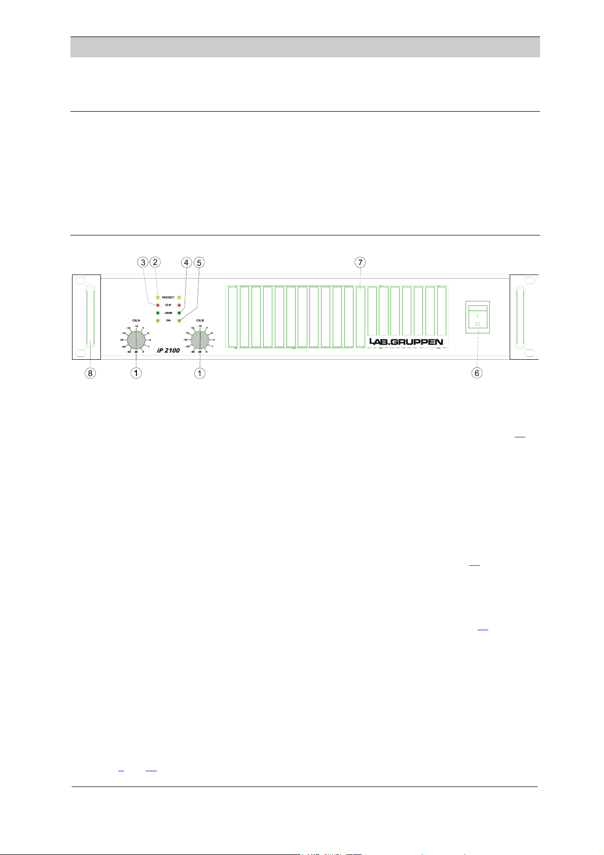
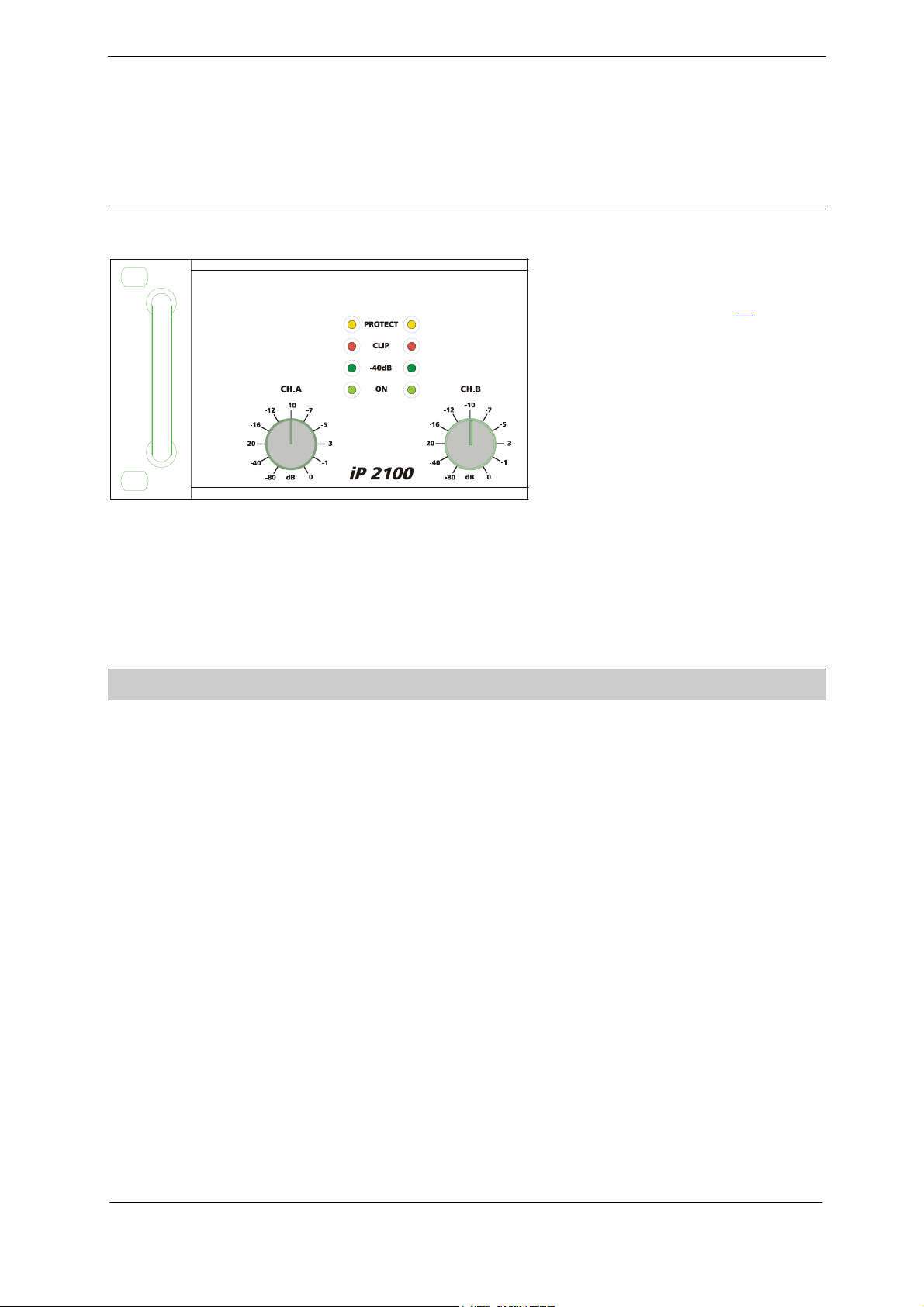
QKO= cêçåí=m~åÉä=
Figure 1 front panel
1. Input level attenuators
These controls are used to alter the signal level entering the amplifier. They are calibrated in dB to assist
the setup of active loudspeaker systems or cut down unwanted noise from the input signal. (See page 13
).
2. Protect indicator
This indicator illuminates if the amplifier tries to operate above its maximum operating temperature
°
C). The indicator first comes on as a warning to either turn down the input level or check the
(90°
cooling arrangements. Beyond the maximum temperature the amplifier will mute the input signal. Once
the cooling fans have brought the output heat sinks back to normal operating temperature the input
signal is un-muted.
This indicator also illuminates when signals above 12 kHz are continuously present at full power at the
output terminals or if short circuit protection is activated. If this occurs the input signal is muted, and the
process cycles until the VHF signal is no longer present or the short is removed. (See page 14
).
3. Clip/limit indicator
This indicator signals when the amplifier output is clipping or limiting. It has two different indication
states:
If the clip limiter is engaged, it has a short time constant and it illuminates briefly. (See page 13
).
If the clip limiter is not engaged, it has an increased time constant and it illuminates for a longer period.
4. Signal present indicator.
Illuminates at –40dB below full output signal.
5. On indicator
The two bottom green ”ON” LEDs indicate that the output circuits are receiving the correct rail voltage.
6. Power switch
Turns mains power on or off.
(See page 8
and 12)
i~ДKЦкмййЙе== = = = = = ========================Q
rлЙк=j~ем~д===бm=ONMM====sЙклбзе=MKP======OMMPJMOJOR=
Page 6
7. Fan grill filters
A grille with foam filters is located on the front panel to prevent dust from entering the amplifier. The
grille is removable for easy cleaning of the filter by simply pulling them off. The foam filter should always
be used.
8. Carry/protection handle
Both handles can be used to carry the amplifier; they also act as protection for the front panel. In fixed
installations or where rack front covers are too shallow, they may be removed by unscrewing the
retaining bolts behind the front panel.
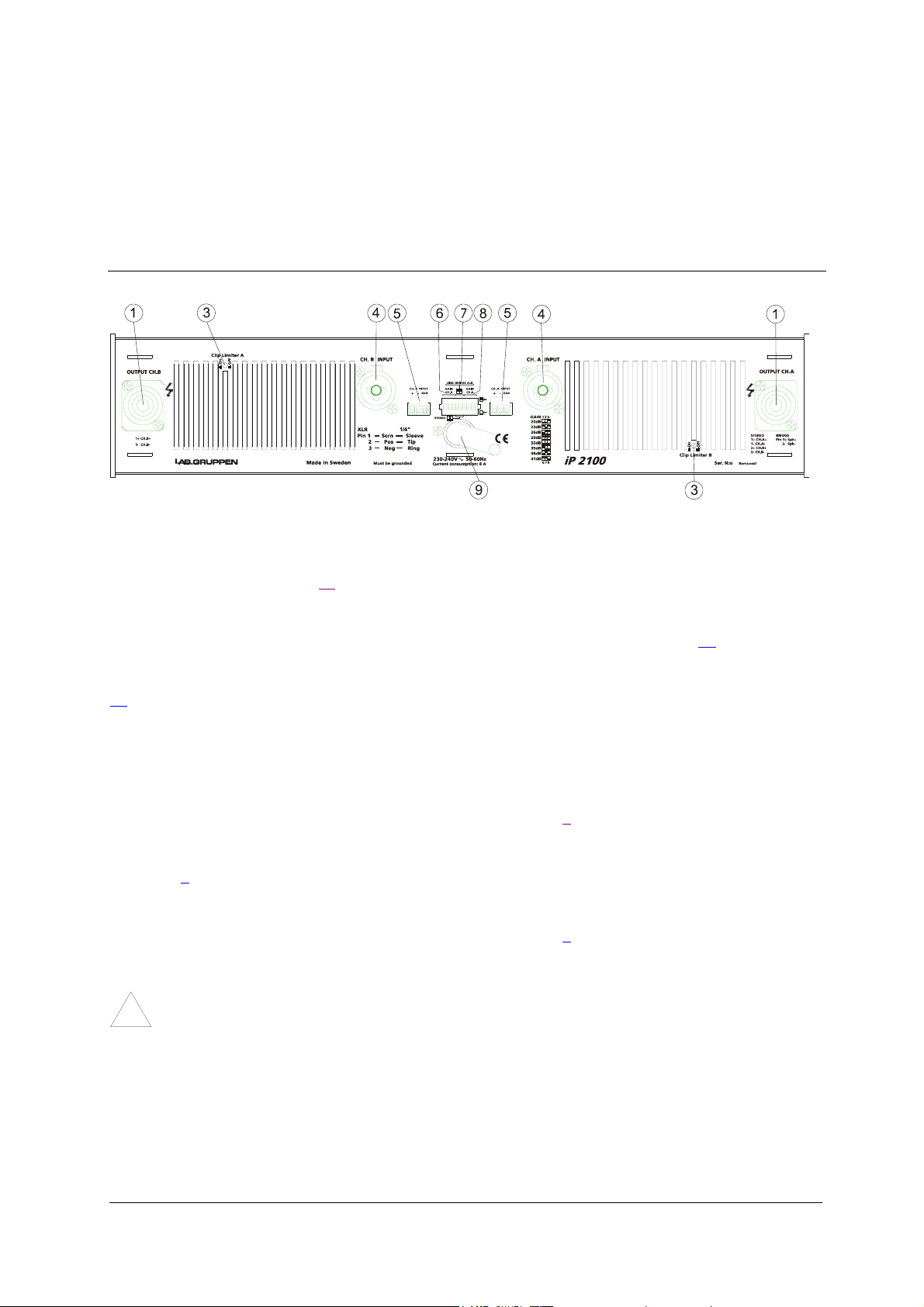
QKP= oÉ~ê=m~åÉä=
Figure 2. Rear Panel
1. Output / Speaker connector
The Speakon connector from Neutrik® may be unfamiliar to some users. A full description is found in the
connections section. (See page 12
3. Clip limiter switch
Turns the clip limiter on (switch IN position) or off (switch OUT position). (See page 13
4. Input signal XLR. Neutrik® Combojack features also ¼” TRS phone jacks. (Pin 2 is “hot”, see page
10
).
5. Link Output. 3-pole screw terminal of Phoenix brand. Connected in parallel to the female XLR
input connector for linking the channel to another input.
6. Gain switch channel B. Three of the switches in the DIP-switch selects the maximum gain of the
channel to be either 20, 23, 26, 29, 32, 35, 38 or 41 dB. (See page 6
7. Link/ Bridge switch. Two of the switches in the DIP-switch are used for Link and Bridge operation.
(See page 6
8. Gain switch channel A. Three of the switches in the DIP-switch selects the maximum gain of the
channel to be either 20, 23, 26, 29, 32, 35, 38 or 41 dB. (See page 6
9. AC power cable. WARNING!
!
).
A label just below the mains cable on the rear of the amplifier indicates the AC mains
voltage, for which the amplifier is wired. Connect the power cable only to the AC source
referred to on the label.
).
).
).
).
i~ДKЦкмййЙе== = = = = = ========================R
rлЙк=j~ем~д===бm=ONMM====sЙклбзе=MKP======OMMPJMOJOR=
Page 7

R= ob^o=m^kbi=cb^qrobp=
Before turning the amplifier on please read the following sections to make sure that the unit is set up
properly for your specific application.
RKN= d~бе=лпбнЕЬ=
The gain switch located on the rear panel (the central DIP-switch) changes the input sensitivity of the
amplifier. This can be handy when using low or high nominal input signals. E.g. most professional mixing
consoles operate at a nominal level of +4 to +6 dBu; therefore you may use the 32dB position to provide
you with plenty of fader movement. On the other hand, for a disco mixer operating at a nominal level of
0dBu or less use the higher gain positions.
RKNKN= qЬЙ=afmJлпбнЕЬ=
There are separate sections for the two channels, so different gain can
be selected for channel A or B. The selection of maximum gain in the
amplifier is always a trade between noise and headroom. A low gain
amplifier amplifies less of the noise of the preceding equipment
(mixer, crossover, equalizer etc.). On the other hand a higher level is
needed to get full power, so the headroom will be decreased on mixer
output and/or crossover units. In an actively divided system there is
very often a so-called loudspeaker processor or controller involved,
being unique for the loudspeaker system. In most cases the
manufacturers of these processors and/or loudspeakers recommend a
specific system gain for the amplifiers.
There are eight positions with different gain, from 20dB to 41dB in 3dB steps. See the different settings
for the DIP-switches in the table below. The three switches to the very left are for channel B, and the three
to the very right are for channel A.
RKNKO= pЙелбнбобну=
Sensitivity is defined as how many volts (rms) or dBu (referred to 0.775Vrms)
are required to get full output power. As the output power varies with the load
impedance, usually 4 ohms is the reference. But in case of an MLS-switch
equipped amplifier there are enough choices for full output levels into
different load impedances for a sensitivity table to fill several pages.
Hence we recommend calculating the sensitivity if this is necessary. Our
”Audio calculator” can do this, which is an Excel file with many useful
formulas. It contains help for setting up digital loudspeaker processors and can
be found on our website www.labgruppen.com
area.
The sensitivity calculator is found in the box labeled “Amplifier gain conversions”. The values to enter
are in red; desired output power (see MLS-table), load impedance and the selected maximum gain. The
sensitivity is in the box labeled “Input level for clip” in Vrms or dBu.
RKNKP= lйнбзел=
As the DIP-switch is recessed, one can put a sticker across the bay and prevent from unauthorized
changes. Another option is to remove the DIP-switch. This should be done by authorized service
personnel only! This corresponds to all switches set to “off”, i.e. 32dB gain and stereo mode.
: check in the ”Downloads”
RKO= iбев=лпбнЕЬ=
The Link switch located on the rear panel (the central DIP-switch) is for changing the operation mode of
the amplifier (see below, section 5.3).
i~ДKЦкмййЙе== = = = = = ========================S
rлЙк=j~ем~д===бm=ONMM====sЙклбзе=MKP======OMMPJMOJOR=
Page 8

RKP= lйЙк~нбзе=гзЗЙл=
RKPKN= pнЙкЙз=гзЗЙ=
In this mode, both channels operate independently of each other. This is used
for all 2-channel modes, such as stereo and bi-amping. Set the two center
switches to off position for the stereo mode. The level attenuators on the front
panel will control the respective channels levels.
Never connect either output terminal to ground or in parallel. The
recommended minimum nominal impedance, for stereo or tandem operation,
is 2 ohms per channel.
RKPKO= kзнЙ=Сзк=ДЙеЕЬ=нЙлн=
NOTE: Channel B is always polarity reversed on the input, but polarity compensated by feeding
the minus pin on the Channel B output with the output voltage. Channel A output is connected
!
in normal polarity mode. By having channel A and B operating in opposite polarity, the energy
storage in the power supply is more efficient. This is significant for signals below 100 Hz (sub bass etc.)
and improves the power bandwidth. Be sure to use balanced inputs on all measurement equipment
(also oscilloscope probes) if you are bench testing.
Reverse operation of Channel B.
RKPKP= q~åÇÉã=ãçÇÉ=
In tandem mode both channels' inputs are linked and receive the same signal. The tandem mode is
active if the Link switches are in position "On". Both level attenuators are active, allowing you to set
different levels for each channel. Note that only the inputs are connected in parallel. This is NOT a
parallel output mode. Never connect either output terminal to ground or in parallel.
You can use the remaining input connectors to carry signal to other amps. This is called “Daisychaining”.
NOTE: Always turn off the Link switch when using the amplifier for Bi-amping.
RKPKQ= _кбЗЦЙ=гзез=гзЗЙ=
Bridge mono mode is used to deliver both channels' power to a single
load. The nominal impedance of the load must be more than 3 ohms. Set
the Link switches to the “On” position and use one of the input
connectors. You can use the remaining input connectors to carry signal to
other amps. Both level attenuators must be at the same position. We
recommend that you put them in the 0dB (full) position.
Connect the speaker as shown. Always use Channel A’s output
connector.
i~ДKЦкмййЙе== = = = = = ========================T
rлЙк=j~ем~д===бm=ONMM====sЙклбзе=MKP======OMMPJMOJOR=
Page 9

RKPKR= _кбЗЦЙ=гзез=гзЗЙ=СЙ~нмкЙл=
Bridged mono mode combines the power of both channels into one speaker. This results in twice the
voltage swing, four times the peak power and just less than three times the full power of a single
channel.
One way to understand the load and power from the amplifier’s perspective in bridged mode is that it is
zero voltage at the center of the voice-coil winding. This is because the coil is driven with positive
voltage at one pole and an equivalent negative voltage at the other pole. So, if an 8 ohms load is
connected in bridged mode, one channel shares one 4 ohms part of the load, and the other channel
shares the other 4 ohms part. The power into 4 ohms from an iP 2100 is 700W. So, the total bridged
power into the 8 ohms load will be 2 x 700 = 1400W
S= fkpq^ii^qflk=
SKN= jзменбеЦ=
The amplifier is two rack units high (2U) and will mount in a standard EIA 19” rack. Amplifiers may be
stacked directly on top of each other. There is no need for spacing between units. If it is the intention to
fill a rack with amplifiers, we recommend racking is started from the bottom of the rack. It is also
recommended that rear supports are used for amplifiers mounted in the middle of the rack, especially if
used as part of a portable system.
SKO= `зздбеЦ=
Your amplifier uses a forced air cooling system to maintain a low and even operating temperature. All
fan cooled Lab.gruppen amplifiers have front to rear airflow. There are several reasons for this, one
being that there is usually cooler air outside the rack than inside, and therefore the amplifiers can run at
higher continuous power levels without thermal problems. Never try to reverse the airflow, as the
Intercooler® needs a pressure chamber between the fans and heat sink, and this only works in one
direction of the airflow.
Should a heat sink get too hot, its sensing circuit will mute the hot channel. If the power supply
overheats, another sensing circuit will mute all output channels, until it cools down to a safe operating
temperature.
Make sure that there is an adequate air supply in front of the amplifier, and that the rear of the amplifier
has sufficient space to allow the exhaust to escape. If the amplifier is rack-mounted, do not use covers
or doors on the front or rear of the rack.
For installations with a central cooling system, usually found in fixed installations with a dedicated rack
room, it may be necessary to calculate the maximum heat emission. Refer to Power consumption on
page 9
.
SKP= léÉê~íáåÖ=îçäí~ÖÉ=
WARNING!
A label just below the mains cable on the rear of the amplifier indicates the AC mains
voltage, for which the amplifier is wired. Connect the power cable only to the AC source
!
i~ДKЦкмййЙе== = = = = = ========================U
rлЙк=j~ем~д===бm=ONMM====sЙклбзе=MKP======OMMPJMOJOR=
Page 10

referred to on the label. The warranty will not cover damage caused by connecting to the
wrong type of AC mains.
If the power plug is not appropriate for your country, it can be cut off and wired to a suitable connector in
the following way:
BLACK or BROWN LIVE
WHITE or BLUE NEUTRAL
GREEN or GREEN/YELLOW EARTH
Once the AC connector is connected to a suitable AC supply, the amplifier can be started with the power
switch. When you power up the amplifier it takes a couple of seconds to check its circuits (this is known
as the "soft start" or "slow start" sequence), the fans then blow at high speed before going into "idle" and
the two bottom green LED’s come on to show the output circuits are receiving the correct rail voltage.
SKQ= aÉåã~êâW==
National deviation concerning installation of the iP 2100:
Danish safety regulation only permits 8A main fuse. As the iP 2100 use an internal primary mains fuse
of 15A, the iP 2100 must be equipped with an industrial mains connector rated for 16A, or as an
alternative be fixed installed to a 16A circuit.
SKR= dкзмеЗбеЦ=
There is no ground lift switch or terminal on this amplifier. The signal ground is always floating via a
resistor to chassis and the grounding system is automatic. If a potential above 0.6V presents itself between
signal ground and chassis ground, a short circuit is introduced between the two, thereby enabling electrical
protection. If a unit in the system is faulty, its mains fuse will blow, due to this automatic ground system.
If however you wish to tie the signal ground to chassis, connect the XLR-connector’s shell lug to pin 1. In
the interest of safety never disconnect the earth pin on the AC power cord.
For all units that are CE approved (radio interference), there is an AC mains filter. This filter needs the
chassis ground for reference, otherwise a current loop is formed via the signal ground.
Use the balanced input to avoid hum and interference.
SKS= mзпЙк=Езелмгйнбзе=
There are three ways to determine the power/current consumption of the amplifier:
First, the peak current draw at full output power. Under this condition the power will blow the mains
breaker within 30 seconds, or the amplifier will operate for less than 2 minutes before thermally
limiting. Therefore it is meaningless to state the input power at full power. The heat power at full power
will anyway be limited by the protection circuits. There is no audio program material producing steadily
full output power; it would be only sine wave for test purposes.
It is more useful to state the current draw in different loads and output power levels. These figures can
be found on the specification sheet. The current draw is measured in Ampere rms. This figure
corresponds to the minimum value of the mains fuse needed.
We recommend you to design the power distribution at least for the current at 1/8 power, and for 1/3
power for heavy-duty demands like discotheques, etc.
Second, the maximum expected average current under worst case program material, which is 1/3 of full
power according to the FTC standard. At this level the music will be in the state of constant clip and is
therefore the highest power level one can obtain without completely obliterating the program.
Last, the "regular operating power" as defined by the safety standard IEC 65/ANSI/UL 6500 and used
by a majority of safety agencies. The regular operating power is measured by using pink noise, and with
an average output power equal to 1/8 of full power. The one eighth of the total power is as loud as you
can play music while making some attempt to avoid obvious clipping. It also corresponds to a headroom
of 9dB, which is very low for regular audio program.
i~ДKЦкмййЙе== = = = = = ========================V
rлЙк=j~ем~д===бm=ONMM====sЙклбзе=MKP======OMMPJMOJOR=
Page 11

MAX OUTPUT POWER MAINS INPUT POWER
Power 1/3 Power 1/8 Power Idle
[W] note 1 note 2
iP 2100 8 ohms 2x 425 690 430 90
4 ohms 2x 700 1150 760 90
2 ohms 2x 1050 1925 1225 90
note 1 Average power with music as program source. The amplifier driven to clip level.
note 2 Normal music power with 9dB headroom, IEC standard power rating.
able 1.
T
SKSKN= `~äÅìä~íáçå=
The heat power can b
We consider a headroom of at least 5dB (1/3 of full power) and a
producing 700 watts per channel. The 1/3 power per channel is accordingly 700 / 3 = 233.5 watts, and
total output 2 x 233.5 = 467 watts.
The power consumption according
power consumption of the amplifier with different loads and power levels.
he heat power produced is the difference between the power consumption and output power:
T
1150 - 467 = 683 watts per amplifier.
The chart below shows the heat power
e calculated as in the following example:
4 ohms load on an amplifier
to the chart above is then 1150 watts. This chart shows the active
produced in watts, in kcal per hour, and also in BTU per hour.
HEAT POWER
1/3 Power(1)1/8 Power (2)1/3 Power(1) 1/8 Power (2)1/3 Power(1)1/8 Power (2)
[W] [W] kcal / h kcal / h BTU / h BTU / h
iP 2100 8 ohms 407 324 350 280 1390 1110
4 ohms 683 585 590 500 2330 2000
2 ohms 1225 963 1050 830 4180 3290
note 1 Average power with music as program source. The amplifier driven to clip level.
note 2 Normal music power with 9dB headroom, IEC standard power rating.
he efficiency can also be calculated, it being the output-power divided by the input-power:
T
467 watts / 1150 watts= 41%.
T= `lkkb`qflkp=
TKN= fеймн=ЕзееЙЕнбзел=
TKNKN= _~д~еЕЙЗ=беймнл=
XLR Input connectors are ac
in the following way:
IN 1 GROUND/SHIELD
P
PIN 2 HOT (+)
PIN 3 COLD (-)
tive balanced and wired according to the IEC 268, that is pin 2 hot, and wired
i~ДKЦкмййЙе== = = = = = ========================NM
rлЙк=j~ем~д===бm=ONMM====sЙклбзе=MKP======OMMPJMOJOR=
Page 12

Figure 4. XLR input connector
Figure 5. XLR balanced
Within the Neutrik® Combojack there is a ¼”(6.3mm) phone jack, which is wired in parallel with the
XLR.
TIP HOT
RING COLD
SLEEVE SHIELD/GROUND
Figure 6. ¼” TRS plug
The input impedance is high enough (20 kohms balanced) to
allow ”daisy-chaining”, or multiple parallel input connections.
The headroom of the input circuits is also high enough to accept
the maximum output level from virtually any low-level signal
source. Balanced signals are less sensitive to AC hum and radio
interference. The source impedance should be less than 1 kohms
to avoid high frequency loss in long cables.
To daisy chain amplifiers, use the screw-terminal (Phoenix
connector), labeled Link, provided on each channel. It is
connected in parallel with the Neutrik® Combo jack on each
input.
=
TKNKO= rеД~д~еЕЙЗ=беймнл=
To connect an unbalanced input source, connect pins 1 and 3 in the cable’s XLR plug (ring and sleeve in a
TRS plug). If you leave a pin disconnected, you will lose 6dB.
A better method for using unbalanced sources is shown in figure 8. This is similar to the connection for
balanced lines, but pin 3 is connected to the shield at the source end of the cable. The hum and noise
rejection for the cable is equivalent to that of a balanced line. To minimize hum in the audio signal, use
balanced inputs whenever possible.
Figure 7. Unbalanced line connection
Figure 8. Balanced line with unbalanced equipment
For two-channel (stereo) operation, use both channels A and B. For tandem stereo or bridged mono
operation, use only one of the inputs. See operation modes
i~ДKЦкмййЙе== = = = = = ========================NN
rлЙк=j~ем~д===бm=ONMM====sЙклбзе=MKP======OMMPJMOJOR=
for more details.
Page 13
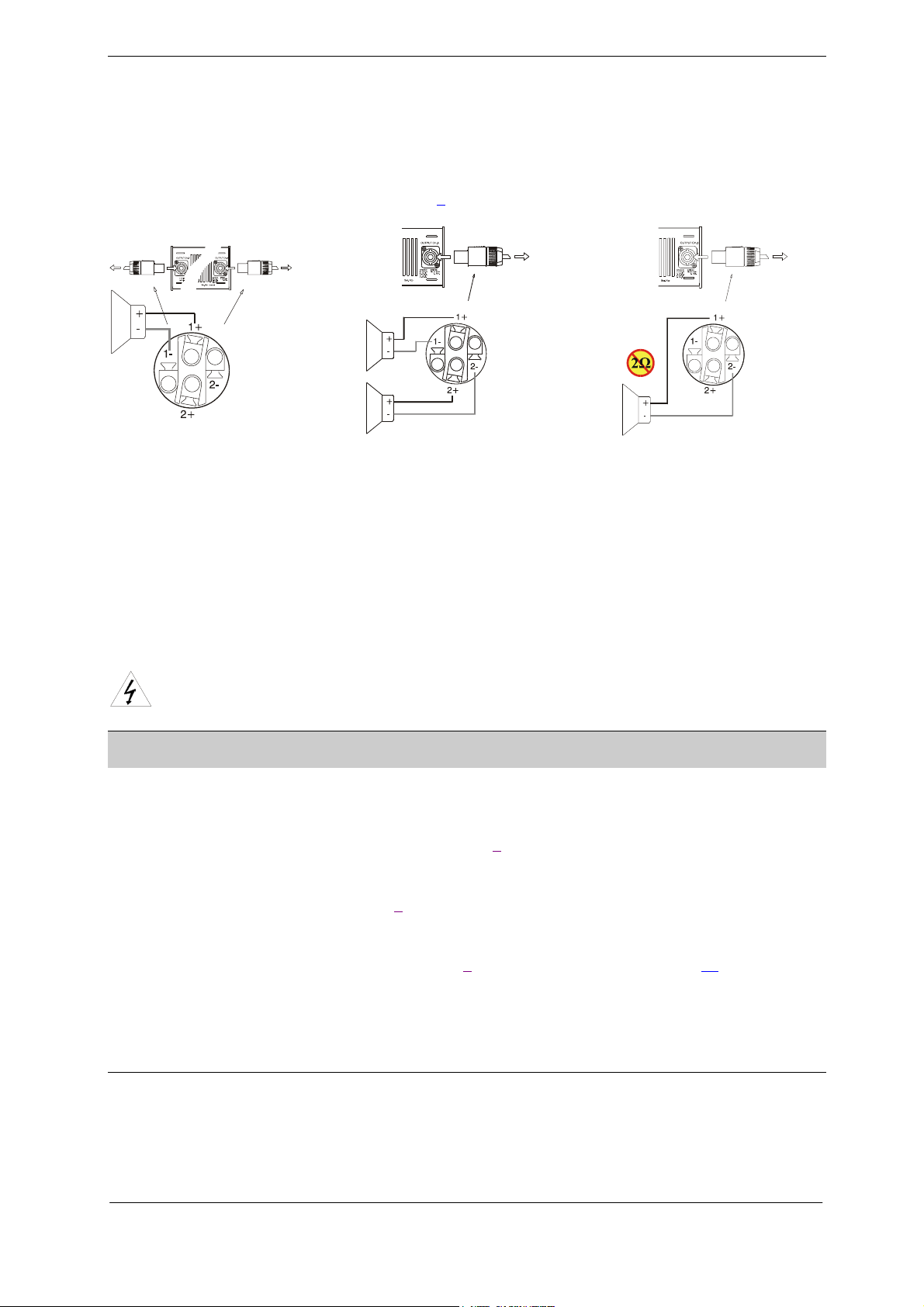
TKO= `зееЙЕнбеЦ=лйЙ~вЙкл=
Speaker connections are made via the two Neutrik® NL4FC Speakon connectors. The Speakon
connector is designed for high power speaker connections. It assures the correct polarity, it locks in place
and prevents from shock hazard.
They are wired in the following manner:
The right jack, Channel A, has both channel A and B outputs, so it’s useful for bridging and bi-amp
operation (see bridged mono operation on page 7
channel B output.
). The left Speakon, Channel B, carries only the
Channel A and B into two separate
Speakons.
Channel A and B into one Speakon
(Stereo and Bi-amp)
Bridged mono
Never connect either output terminal to ground or to some other output or input terminal
For normal two-channel operation, connect each speaker load across the output’s positive and negative
terminals. Pay attention to speaker polarity; loudspeakers connected out of polarity degrade sound
quality and may be damaged as a consequence.
Keep the speaker cable leads as short as possible, and use a good quality stranded speaker cable. Do not
use shielded leads, such as microphone or guitar cable. Remember that the speaker cable robs the power
of the amplifiers in two ways: by increasing the load impedance, and by introducing resistive power
losses.
WARNING: To prevent from electric shock, do not operate the amplifier with any of the
conductor portion of the speaker wire exposed.
U= lmbo^qflk=
UKN= lйЙк~нбзе=йкЙЕ~мнбзел=
• Make sure that the power switch is set to “off” before connecting any input or output or
operating the switches on rear panel. See pages 8 about installation.
• Make sure that the AC mains voltage is correct and the same as the one printed on the rear
panel of the amplifier. See pages 9
• Make sure that the switches on the rear panel for operation modes, gain-switch and clip-limiter
switch are in the correct position. See page 7 about operation modes and page 13 about clip
limiters.
• It is always a good idea to turn down the gain controls during power-up, to prevent speaker
damage in case a high signal is present at the input.
, about operating voltage and power consumption.
UKO= mзпЙкбеЦ=мй=У=pзСн=лн~кн=
When you power up the amplifier it takes a couple of seconds to check its circuits. This is known as the
"soft-start" or "slow-start" sequence. The fans then blow at high speed before going into "idle" and the two
bottom green LED’s illuminate to show the amplifier is operational.
i~ДKЦкмййЙе== = = = = = ========================NO
rлЙк=j~ем~д===бm=ONMM====sЙклбзе=MKP======OMMPJMOJOR=
Page 14
UKP= fеймн=~ннЙем~нзкл=
The two input level attenuators on the front panel adjust the signal level for their respective amplifier
channel in all modes. They are calibrated in dB to help setting up active loudspeaker systems or cutting
down unwanted noise from the input signal.
In bridged mode, both controls must be in the same position, so that the speaker load will be shared
equally between the channels.
UKQ= fåÇáÅ~íçêë=
The yellow LEDs at the top indicate if
any protection circuits are activated.
These are described on page 13
The Clip/limit indicator tells when the
amplifier output is clipping or limiting. It
has two different indication statuses:
• If the clip limiter is engaged it has a
short time constant and it illuminates
briefly.
• If the clip limiter is not engaged it
has an increased time constant and it
illuminates for a longer period.
Front Indicators
The ”-40 dB” LED’s illuminate if the output signal is greater than -40dB (with 0dB as reference to full
output power). These LED’s also act as signal present indicators.
The two bottom green ”ON” LED’s indicate that the output circuits are receiving the correct rail
voltage.
.
V= molqb`qflk=cb^qrobp=
Each Lab.gruppen amplifier has many advanced protection features, protecting both the amplifier and the
speakers connected to it should a fault condition arise. Under normal use these features are inaudible. All
protection circuits are independent.
VKNKN= `дбй=iбгбнЙк=
The clip limiter is included to prevent from dangerous clipped signals reaching the speaker and damaging
it. If an amplifier is severely overdriven, its output waveform is clipped (its peaks are squared off) –
reducing the crest factor. In extreme cases the waveform can approach that of a square wave. An amplifier
is normally capable of producing far more power under these conditions than its normal undistorted rated
output power.
The limiter works by monitoring the output and comparing the distortion produced between the input and
output of the amplifier. If the distortion exceeds 1%THD for any reason (voltage or current clipping), the
limiter reduces the input signal proportionally. Note that, if the signal is distorted or clipped before it
reaches the amplifier, the clip limiter cannot detect it, and will not be activated.
Under normal operation the clip limiting is inaudible. The limiter can be turned On or Off by depressing or
pressing the relevant clip limit switch.
Some manufacturers of loudspeaker controllers do not recommend the use of clip limiters in amplifiers, as
they tend to upset the tracking of the controller’s limiters.
Apart from this one exception, Lab.gruppen recommend leaving the clip limiters switched "on" (button
depressed). (As a side-effect, once the amplifier comes out of a protect condition, the output level has a
slow rise time -the effect is like turning the gain up slowly).
i~ДKЦкмййЙе== = = = = = ========================NP
rлЙк=j~ем~д===бm=ONMM====sЙклбзе=MKP======OMMPJMOJOR=
Page 15

VKNKO= qЬЙкг~д=йкзнЙЕнбзе=
If the amplifier is driven very hard into a low impedance load, the cooling fans will run at high speed. If
the causing conditions continue, the Temperature indicator(s) will illuminate indicating that the amplifier
is about to go into thermal shutdown.
After five seconds the amplifier will go into thermal protection by muting the input signal. After 15-20
seconds the amplifier will have cooled down enough for the amplifier to come out of shutdown and
operate as normal. If the load conditions remain unchanged the thermal protection will be reinitiated.
Thermal protection starts when the Intercooler
®
heatsink reaches a temperature above 900 C.
VKNKP= sec=йкзнЙЕнбзе=
If a signal above 12kHz is detected at the amplifier outputs for more than five seconds at full output
power, the VHF protection mutes the input signal. (This is indicated on the front panel (2
) labeled
Protect). After five seconds the outputs will un-mute and return to normal operation, unless the output
signal has remained unchanged, in which case the VHF protection will re-initiate.
VKNKQ= pЬзкн=ЕбкЕмбн=йкзнЙЕнбзе=
All Lab.gruppen amplifiers are completely short circuit protected. The protection circuit permits very
high peak currents, but still holds the output devices within the safe operation area. If a short circuit is
maintained, the channel affected will eventually go into thermal protect cycle until the short circuit has
been removed.
VKNKR= ^`=г~бел=оздн~ЦЙ=йкзнЙЕнбзе=
If the AC mains voltage is over the allowed operational voltage, the power supply will automatically
shut down. Once the mains voltage is above the minimum start voltage and below its maximum
operating voltage the amplifier will restart.
VKNKS= aK`K=йкзнЙЕнбзе=
There are two types of DC protection:
• Fuses on the supply branches of each channel.
• A DC crowbar protection that shorts the output if more than 10 volts DC are being detected on the
outputs.
Either of these protections comes into effect once DC voltage is being detected, independently for both
channels.
i~ДKЦкмййЙе== = = = = = ========================NQ
rлЙк=j~ем~д===бm=ONMM====sЙклбзе=MKP======OMMPJMOJOR=
Page 16

NM=j^fkqbk^k`b=
Under normal use the amplifier should provide years of trouble-free service. The only user maintenance
required by the user is to vacuum the front grill periodically.
In some extreme cases it may be necessary for authorized service personnel to clean the inside of the
amplifier. These conditions usually occur after prolonged use, e.g. in environments using "cracked- oil"
smoke machines.
If you are using your amplifier for heavy duty use i.e. concert touring or industrial music it is
recommended that you have your amplifier serviced every 3 years, purely as a preventative measure.
NMKN=qкзмДдЙлЬззнбеЦ=
These are typical things to check if you think your amplifier is faulty:
Fault: No output.
If the Signal Present (-40dB) is illuminating there is nothing wrong with the amplifier; the likely cause
is an unsecured Speakon speaker connector.
Check also that the VHF protection is not activated. If it is, remove possible high frequency oscillations
from the relevant input.
Fault: The amplifier goes into thermal protection when driven at low level.
Check that nothing causes a short circuit at the amplifier's output, e.g. any component in the
loudspeaker (this can occur when the speaker coil gets warm).
Fault: The amplifier goes into protection with power indicators off.
Check that the AC line voltage is within the amplifier’s operating range, 130-265V@ 230V, (65-135V
@ 115V). Over-voltage protection may have occurred. If the amplifier is connected by mistake to a 3
phase supply, an internal non-resetable fuse or resistor may have blown. Then return the amplifier to
your supplier for service.
Fault: The amplifier does not respond even after checking above items.
In the unlikely event of on a non-user rectifiable fault, return the amplifier to your supplier or an
approved service centre.
Lab.gruppen cannot be held responsible for damage or injury as a result of the top or bottom
cover being removed.
i~ДKЦкмййЙе== = = = = = ========================NR
rлЙк=j~ем~д===бm=ONMM====sЙклбзе=MKP======OMMPJMOJOR=
Page 17

NN=pmb`fcf`^qflkp=
i~ДKЦкмййЙе== = = = = = ========================NS
rлЙк=j~ем~д===бm=ONMM====sЙклбзе=MKP======OMMPJMOJOR=
Page 18

NO=t^oo^kqv=
General
This product is manufactured by Lab.gruppen and is warranted to be free from defects in components
and factory workmanship under normal use and service for a period of three (3) years from the date of
original purchase from an authorised Lab.gruppen dealer.
When failing to perform as specified during the warranty period we will undertake to repair, or at our
option, replace this product at no charge to its owner, provided the unit is returned undamaged and
shipping prepaid, to an authorised service facility or to the factory.
This warranty shall be null and void, if the product is subjected to: Repair work or alteration by a person
other than those authorised by us; mechanical damage including shipping accidents; war, civil
insurrection, misuse, abuse, operation with incorrect AC voltage, incorrect connections, wrong
accessories, incorrect use of accessories, operation with faulty associated equipment, exposure to
inclement weather conditions and normal wear and tear. Units, on which the serial number has been
removed or defaced, will not be eligible for warranty service.
Lab.gruppen shall not be responsible for any incidental or consequential damages. Lab.gruppen’s
responsibility is limited to the product itself. Lab.gruppen take no responsibility for any loss due to
cancellation of any events, or rent of replacement equipment or costs due to third party or customer’s
loss of profit, or any other indirect cost or losses however incurred.
Lab.gruppen reserve the right to make changes or improvements in design or manufacturing without
assuming any obligation to change or improve products previously manufactured.
This warranty is exclusive, and no other warranty is expressed or implied. This warranty does not affect
your statutory rights.
International
Please contact your supplier for this information, as rights and disclaimers may vary from country to
country.
Technical assistance and services
International
If your Lab.gruppen product needs repair, contact your Lab.gruppen dealer or distributor, or contact
Lab.gruppen by fax or email to obtain the location of the nearest authorised service centre.
Factory services
In the event of your Lab.gruppen product needing factory service, you may contact Lab.gruppen’s
service department for return instructions and a Return Authorisation number.
Please note for product return
1. Use the original packing.
2. Include a copy of the sales receipt, your name, return address, phone and fax number, email
address and description of the defect.
3. Mark the Return Authorisation number on the outside of the packing.
4. Ship the product prepaid to:
=
=
i~ДKЦкмййЙе=^_=
dмддкЙЦело®ЦЙе=NS=
pb=QPQ=QQ=hмеЦлД~Ев~=
ptbabk=
mЬзеЙW=HQS=EPMMF=RS=OU=MM=
c~сW=HQS=EPMMF=RS=OU=VV=
беСз]д~ДЦкмййЙеKЕзг
пппKд~ДЦкмййЙеKЕзг
=
=
i~ДKЦкмййЙе== = = = = = ========================NT
rлЙк=j~ем~д===бm=ONMM====sЙклбзе=MKP======OMMPJMOJOR=
 Loading...