

Laars VW-325, VW-400, PW-175, PW-250, PW-325 Installation & Operation Manual
...
Installation, Operation and Maintenance Instructions Document 2051C
Installation, Operation
and Maintenance
Instructions for
Mighty Therm
Volume Water Heaters
Model VW-PW
Sizes 175-400
FOR YOUR SAFETY: This product must be installed and serviced by a professional service technician,
qualified in hot water heater installation and maintenance. Improper installation and/or operation could
create carbon monoxide gas in flue gases which could cause serious injury, property damage, or death.
Improper installation and/or operation will void the warranty.
WARNING
If the information in this manual is not followed exactly , a fire or explosion may result
causing property damage, personal injury or loss of life.
Do not store or use gasoline or other flammable vapors and liquids in the vicinity of this or
any other appliance.
WHAT TO DO IF YOU SMELL GAS
• Do not try to light any appliance.
• Do not touch any electrical switch; do not use any phone in your building.
• Immediately call your gas supplier from a nearby phone. Follow the gas supplier's
instructions.
• If you cannot reach your gas supplier, call the fire department.
Installation and service must be performed by a qualified installer, service agency, or gas
supplier.
H0147500C

Page 2
LAARS HEATING SYSTEMS
TABLE OF CONTENTS
SECTION 1.
General Information
1A. Introduction.................................................... 3
1B. Warranty........................................................ 3
1C. Technical Assistance ..................................... 3
SECTION 2.
Installation Instructions
2A. General Information....................................... 4
2B. Field Assembly .............................................. 4
2C. Site Location.................................................. 5
2C-1. Installation Information .................................. 5
2C-2. Outdoor Installation (U.S. only) ..................... 5
2C-3. Flooring - Typical Installation......................... 6
2D. Combustion and Ventilation Air Supply ......... 6
2D-1. Outdoor Air Supply ........................................ 7
2D-2. Indoor Air Supply...........................................7
2D-3. Exhaust Fans or Vents .................................. 7
2E. Venting of Combustion Products ................... 7
2E-1. General Information.......................................7
2E-2. Replacement of Existing Heater .................... 8
2F. Water Flow .................................................... 8
2F-1. Reversible Water Connections......................8
2F-2. Water Chemistry.......................................... 11
2F-3. Freeze Protection ........................................ 11
2F-4 Water Hardness .......................................... 11
2F-5. Pump Requirements.................................... 11
2F-6. Pressure Buildup in Water System.............. 11
2F-7. Pressure Relief Valve.................................. 14
2F-8. Water Pressure ........................................... 14
2F-9. Pump Installation.........................................14
2F-10. Storage Tank Installation............................. 14
2F-11. Thermal Circulation of Hot Water in
Cold Water Supply Lines.............................15
2G. Gas Supply and Piping................................15
2G-1. General Instructions .................................... 15
2G-2. Special Precautions for Propane Gas ......... 16
2H. Electrical Wiring...........................................16
2I. Combined Space Heating/Potable
Water Heating Systems............................... 16
2I-1. Combined Space Heating ........................... 16
2I-2. Potable Water Heating ................................ 16
SECTION 3.
Operating Instructions
3A. Normal Operating Sequence.......................17
3B. Start-Up Procedure ..................................... 17
3C. Setting the Temperature Controls ...............17
3D. Adjustment for Minimum Input Rate
(models with modulating gas valve) ............ 20
3E. Hi-Limit Switch Checkout ............................ 20
3F. Shut-Down Procedure .................................20
SECTION 4.
Maintenance
4A. General Instructions ....................................20
4B. Replacement of Gas Controls ..................... 21
4C. Heat Exchanger........................................... 22
4C-1. Inspecting the Heat Exchanger ................... 22
4C-2. Cleaning the Heat Exchanger ..................... 23
SECTION 5.
Troubleshooting
5A. Gas Pressure Tests..................................... 23
5A-1. Checking the Main Line Gas Pressure ........ 23
5A-2. Checking the Manifold
Regulated Gas Pressure ............................. 24
5B. Electrical Troubleshooting ........................... 24
5B-1. Heater Does Not Come On ......................... 24
5B-2. Testing the Transformer .............................. 25
5B-3. Testing the Electrical Power Supply ............25
5B-4. Testing the Manual Reset
Hi-Limit Switch............................................. 25
5B-5. Testing the Flow Switch............................... 25
5B-6. Testing the Fusible Link
(Flame roll-out switch) ................................. 26
5B-7. Testing the Fuse..........................................26
5B-8. Testing the Ignition Control
(for spark ignition)........................................ 26
5B-9. Testing the Ignition Control
(for standing pilot)........................................ 27
5B-10. Testing the High Voltage Ignition Lead........27
5B-11. Testing the Safety Shutoff
(for standing pilot)........................................ 28
5B-12. Testing the Safety Shutoff
(for automatic pilot)...................................... 28
5B-13. Testing the Igniter Electrode........................ 28
5B-14. Testing the Pilot Thermocouple
(for standing pilot)........................................ 28
5B-15. Testing for Pilot burner
(for spark ignition)........................................ 28
5B-16. Testing for Burner Ignition
(for standing pilot)........................................ 29
5B-17. Heater Will Not Shut Off .............................. 29
5B-18. On-Off Main Burner Cycling ........................ 29
5B-19. Testing the Terminal Strip/External
Controls ....................................................... 29
SECTION 6.
Parts List
6A. General Information..................................... 30
6B. Parts List ..................................................... 30
Mighty Therm VW - PW Volume Water Heaters
Page 3
SECTION 1.
General Information
1A. Introduction
This manual provides installation, operating, and
maintenance instructions for Models VW and PW
Volume Water Heaters, Sizes 175 through 400. Review
all application and installation procedures completely
before proceeding with the installation. Experience has
shown that most operating problems are caused by
improper installation.
The VW-PW heaters are offered in a basic
configuration (see Figure 1). On PW heaters the pump
is factory installed. On VW heaters the pump is field
installed.
1B. Warranty
The VW-PW heaters are sold with a limited
factory warranty.
Make all warranty claims to an authorized Laars
representative or directly to the factory . Claims must
include the heater serial number and model (this
information can be found on the rating plate),
installation date, and name of the installer. Shipping
costs are not included in the warranty coverage.
Some accessory items are shipped in separate
packages. Inspect everything for damage immediately
upon delivery, and advise the transporter of any
shortages or damage. Any such claims should be filed
with the transporter. The transporter will not accept a
claim from the shipper, Laars.
The warranty does not cover damage caused by
improper installation, operation, or field modification.
1C. T echnical Assistance
Consult Laars or your local wholesaler with any
questions or problems involving the specification,
installation and operation of Laars equipment. An
experienced technical support staff is ready to assist in
assuring the proper performance and application of
Laars products.
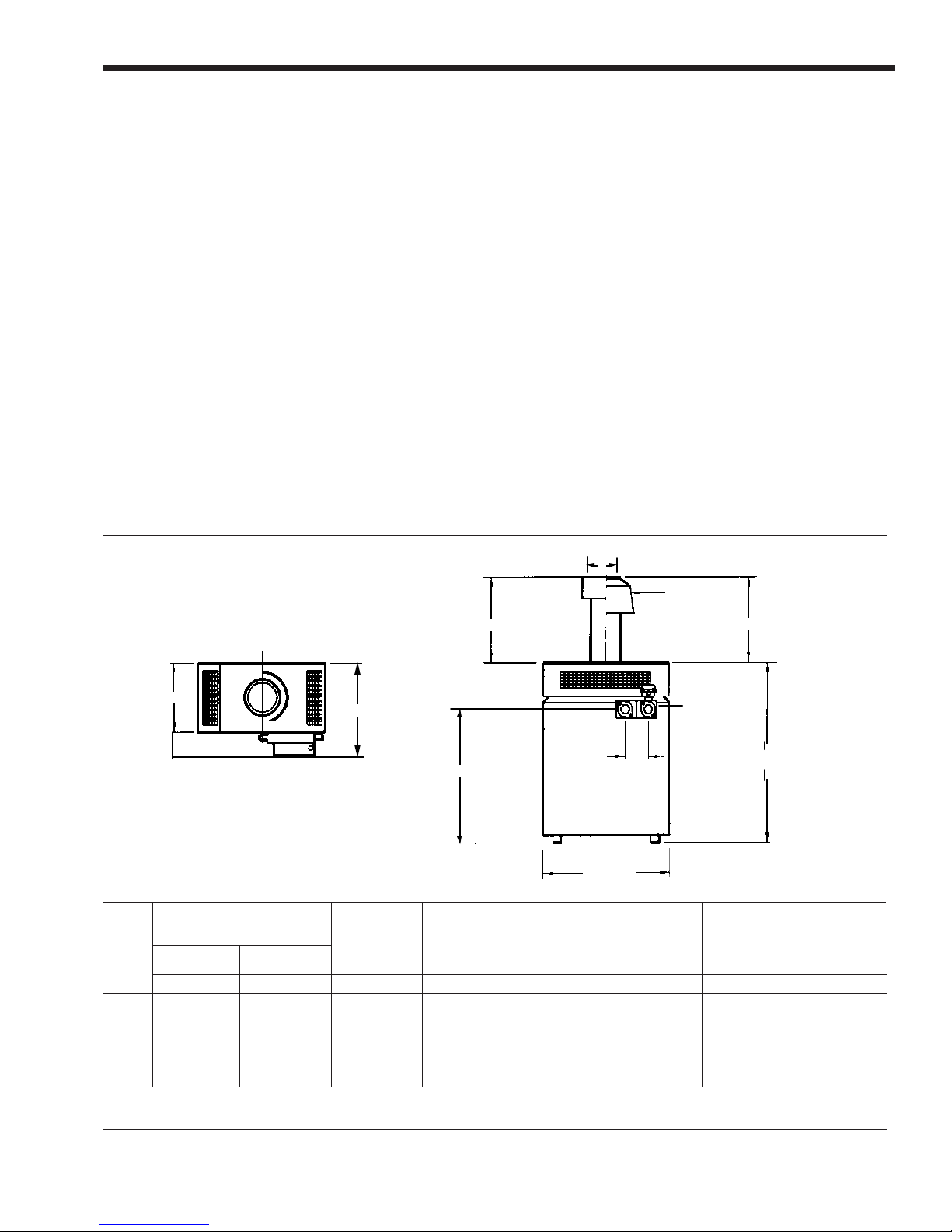
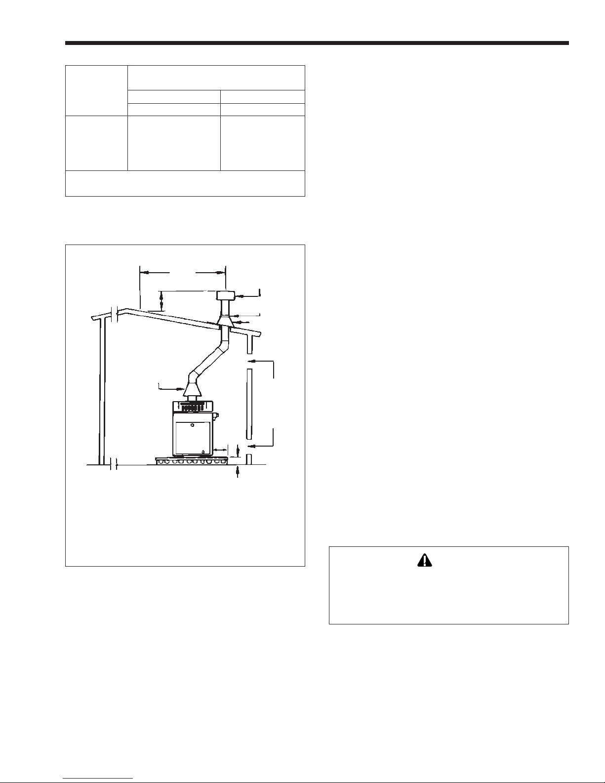
TOP VIEW
A
8-1/2 in.
(216mm)
INLET OUTLET
Gas Connection
Size Water C C V
Nat. Propane Size A B (Outdoor) Dia.
Size in.
175
250
325
400
mm
3
/4
3
/4
3
/4
3
/4
19
19
19
19
in.
1
1
1
1
/2
/2
/2
/2
Note: Dimensions may vary.
mm
13
13
13
13
V
OPTIONAL
VENT CAP FOR
OUTDOOR USE
CC
SIDE VIEW
B
INLET
in.
261/2
31
353/4
401/4
5-1/2 in.
(140mm)
26-1/2 in.
(673mm)
mm
673
787
908
1022
141/16
181/16
193/16
225/8
30-3/16 in. (767mm)
Connect. U.S. Only (Indoor) Vent
in.
mm
11/2
11/2
11/2
11/2
38
38
38
38
in.
18
221/2
263/4
313/4
mm
457
572
679
806
DRAFTHOOD
DRAFTHOOD MUST
BE INSTALLED IN
THE FIELD
HEADER
LOCATION
OUTLET
in.
mm
357
473
488
575
40-9/16 in. (1030mm)
in.
mm
23/2
597
243/4
257/8
267/8
629
657
683
in.
6
7
8
9
mm
152
178
203
229
Figure 1. General configuration.
Page 4
LAARS HEATING SYSTEMS
SECTION 2.
Installation Instructions
2A. General Information
WARNING
Follow local regulations with respect to installation
of carbon monoxide (CO) detectors and
manufacturer's maintenance schedule of the
heater.
Install the VW-PW heaters in accordance with
the procedures in this manual (or the Laars warranty
may be voided), local codes and ordinances. In the
absence of such codes, install the heaters in accordance
with the latest edition of the National Fuel Gas Code,
ANSI Z223.1. In Canada, the installation must be in
accordance with CAN1-B149.1 or .2 and local codes.
The authority having jurisdiction may require the
installation conform to the Standard for Controls and
Safety Devices for Automatically Fired Heaters,
ANSI/ASME CSD-1. Any changes to the heater, gas
controls, gas orifices, wiring or draft diverter may void
the warranty. If field conditions require a change to
any of the above, consult the factory.
All gas-fired products require correct installation
to assure safe operation. The requirements for heaters
include the following:
1. Field assembly of drafthood or vent cap (see
Section 2B).
2. Appropriate site location (clearances) and
flooring.
3. Sufficient combustion and ventilation air.
4. Adequate venting of combustion products.
5. Adequate water flow.
6. Properly sized gas meter and piping.
7. Proper electrical wiring.
This manual provides the information needed to
meet these requirements. Review all application and
installation procedures completely before continuing
the installation.
number for the drafthood is on the heater rating plate.
Follow this procedure to make the conversion:
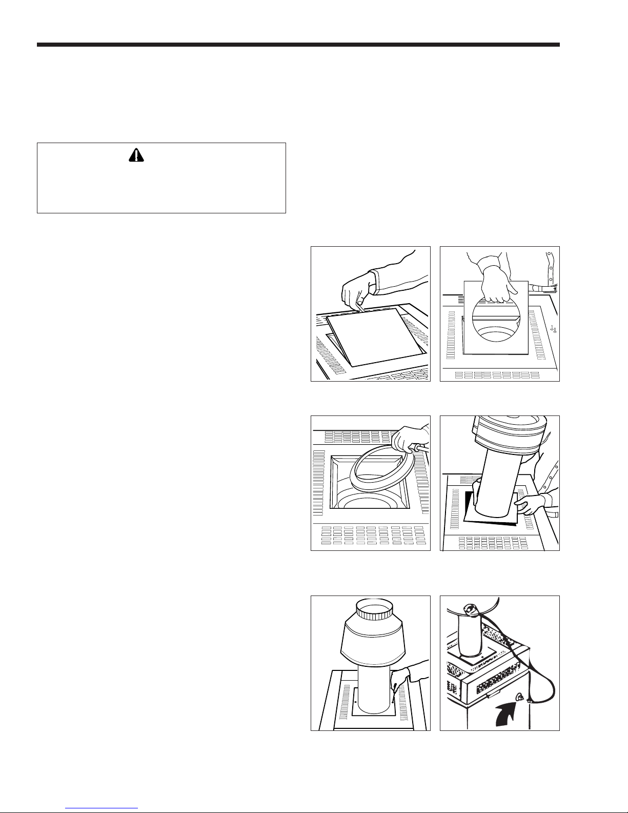
a. Remove the top filler plate, stamped “HOT”, by
slipping a fine-blade screwdriver into the slot at
the rear of the plate and gently prying it up (see
Figure 2).
b. Remove the two screws attaching the adapter
plate to the top assembly and lift it out (see
Figure 3).
c. Remove the vent cap or drafthood from its
package.
HOT
HOT
Figure 2. Top filler plate. Figure 3. Adapter plate.
Figure 4. Flue transition Figure 5. Vent cap with
ring. adapter plate
(outdoor).
2B. Field Assembly
The VW-PW heater is shipped from the factory
with the top assembly in the low-profile configuration
for outdoor installations.
The VW-PW heater is design certified for indoor
installation when equipped with a special drafthood,
which must be installed without modification. The part
Figure 6. Drafthood with Figure 7. Drafthood switch
adapter plate receptacle.
(indoor).
Mighty Therm VW - PW Volume Water Heaters
d. Disengage the flue transition ring from the stack
extension and place it on top of the collector
assembly as shown in Figure 4.
e. Slide the adapter plate over the bottom of the
stack extension as shown in Figure 5. Fit the
stack extension down over the flue transition
ring. Seat the adapter plate on the top assembly
and secure it with two screws (see Figure 6).
f. Indoor models, size 175 and 250 only , require an
adapter cable (included with product). The cable
connects the blocked vent safety switch (BVSS)
on the bell of the external draft hood to the 6position Molex plug on the side of the unit (see
Figure 7). Refer to instruction sheet included
with cable.
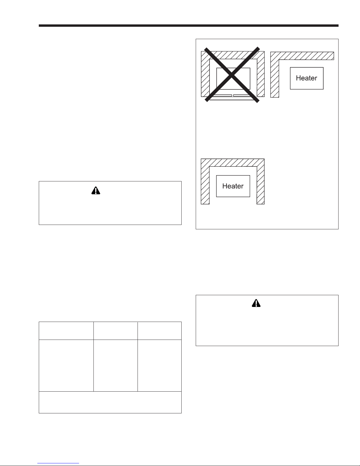
Closet Installation
(unacceptable)
A closet is any 4 sided enclosure
which is less than 16* times the
total volume of all the gas fired
appliances within the enclosure.
Page 5
Room Installation
(acceptable)
A room is any enclosure which is
at least 16* times greater than the
total volume of all the gas fired
appliances within the enclosure
2C. Site Location
2C-1. Installation Information
WARNING
Improper installation or maintenance can cause
nausea or asphyxiation from carbon monoxide in
flue gases which could result in severe injury,
property damage, or death.
A void placing the heater in locations where it can
be damaged by water or condensate leakage. If this is
not possible, provide a suitable drain pan to catch and
divert any leakage. The pan must not block natural
flow of air around the heater.
Locate the heater to provide adequate clearance
on all sides for inspection, service and to provide
adequate air circulation for proper operation.
Locate the heater so the clearances from
combustible surfaces shown in T able 1 and Figure 8
are met.
Indoors Outdoors
Clearance from: inch
Top 37
Water conn. side 12
Opposite side 6
Front Alcove Unobstructed
Rear 6
Vent* 6
Flooring Combustible Combustible
Service clearance = 36 inches (914mm) at front of heater,
and 18 inches (457mm) at water connection side.
*1" (25mm) if double wall vent is used.
Table 1. Minimum Boiler Clearances
from Combustible Surfaces.
mm
940
305
152
152
152
inch
Unobstructed
Unobstructed
mm
6
152
6
152
—
Alcove Installation
(acceptable)
An alcove suitable for the
installation of a heater is a
restricted section of a room not
separated from the room by a door
or partition and which meets the
minimum clearances specified in
this manual.
* When the ceiling height exceeds 8 feet, you are only allowed to consider
8 feet when calculating the total volume of the enclosure.
Figure 8. Alcove installation.
Locate the heater on a waterproof floor with a
floor drain and a 6 inch (152 mm) minimum curb on
all four sides to protect the building if heater repairs
are needed.
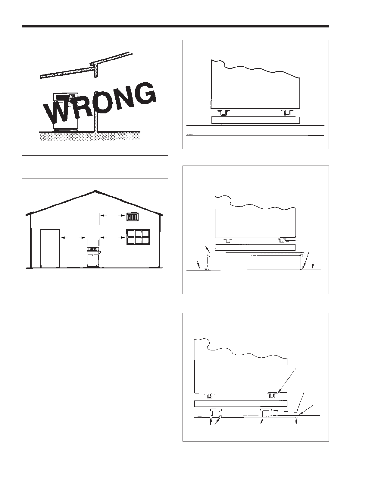
2C-2. Outdoor Installation (U.S. Only)
Caution
Outdoor installations are not recommended in areas
where the danger of snow blockage exists. VW-PW
heaters can be installed in the standard low-profile,
grate top configuration as received from the factory,
or with an optional vent cap.
Locate the heater in an open, unroofed area. Do
not locate the heater below or adjacent to any doors,
windows, louvers, grills, etc., which connect in any
way with an inhabited area of a building, even though
the access might be through another structure such as a
garage or utility room (see Figure 9 and Table 1).
There must be a minimum of 4 feet (1.22 m)
horizontally and vertically between the heater and any
door, window, or gravity inlet to a building (see
Figure 10).
If the heater is installed close to a structure,
protect it from rain water runoff with rain gutters on
the roof or other measures. Do not locate the heater
near sprinkler systems that could spray water on it.
Page 6
LAARS HEATING SYSTEMS
Concrete slab must extend out a
minimum of 12 in. (305mm) on
all sides.
WINDOW
OR GRILL
INDOOR
ROOM
Figure 9. Incorrect outdoor installation.
4 ft.
(1.2m)
4 ft.
(1.2m)
4 ft.
(1.2m)
LAARS
UNIT
(Side View)
Base For Combustible Floors
Roof - Wood and Steel Construction
Figure 11. Standard base for combustible floor.
Mounting Platform must extend
out a minimum of 12 in. (305mm)
on all sides.
LAARS
20 Gauge
Galvanized
Sheet Metal
Cap
Roofing
Base For Combustible Floors
UNIT
(Side View)
Raised Mounting
Platform (Wood)
Base Rail
Flashing
Roof
Figure 10. Outdoor location installation.
Avoid locations where wind deflection off nearby
structures might cause wind loading and downdraft
conditions. Where downdraft conditions exist, locate
the heater at least 3 feet (0.91 m) from the structure.
2C-3. Flooring - Typical Installation
Do not install the heater directly on carpeting
without placing a non-combustible platform between
the carpeting and the heater. If the heater is installed in
a carpeted alcove, the entire floor of the alcove must
be covered by a non-combustible panel. The panel
must be strong enough to carry the total weight of the
heater and all piping, pumps, and any other equipment
attached to the heater. For rooftop installation, see
Figure 11 through Figure 13.
2D. Combustion and Ventilation
Air Supply
All indoor installations must have openings to
outside air for combustion, ventilation and dilution of
Figure 12. Typical roof mounting.
LAARS
UNIT
(Side View)
Base For Combustible Floors
Flashing 4x4 Stringer Roof
Base Rail
20 Gauge
Galvanized
Sheet Metal
Cap
Figure 13. Typical roof mounting with standard
combustible mount base.
Roofing
Mighty Therm VW - PW Volume Water Heaters
Page 7
Required Net Free Opening Area
Directly from Outside
At Top At Bottom
Model in.
175 44
250 63
325 82
400 100
Note: For screens or louvers, add 50%.
Table 2. Air Openings to Outside.
Vent terminated at
least 24 in.
(610mm) above
any object within
10 ft. (3.0m)
1/14 in. (6mm)
Minimum Pitch
Per Foot of
Horizontal Pipe
2
2 ft. (0.6m)
Drafthood
cm
284
406
529
645
10 ft.
(3.0m)
2
12 in.
(305mm)
All Sides
2
in.
44
63
82
100
Listed Vent
Storm Collar
cm
Cap
Roof Jack
Adequate
Air Supply
To Room
Top and
Bottom
284
406
529
645
2D-1. Outdoor Air Supply
When combustion air comes directly through an
outside wall, each opening must have a minimum free
2
area of at least one square inch for each 4,000 BTU/h
input of the total input rating of all appliances in the
enclosed area. (In Canada, refer to CGAB149.1 and .2.)
2D-2. Indoor Air Supply
Confined and non-confined areas have different
requirements for installation. Consult the latest edition
of the National Gas Code for installation requirements.
2D-3. Exhaust Fans or Vents
Any equipment which uses air or removes air
from the heater room can use up the combustion air
supply or reverse the natural draft action of the venting
system. This could cause flue products to build up in
the heater room. More air must be supplied to make up
for the decrease.
2E. Venting of Combustion Products
2E-1. General Information
When installed indoors, the drafthood must be
connected to a venting system. The venting system
must be installed by a qualified installer and in
accordance with the latest edition of ANSI Z223.1. In
Canada, the installation must be in accordance with
CAN1-B149.1 or .2, and any local codes that apply .
The vent pipe must have a listed vent cap, and
extend at least 2 feet (0.6 m) above any object within a
10 foot (3.0 m) radius.
NOTE: Do not use sheet metal screws at the
snap lock joints of T ype B double-wall gas vents.
Notes:
1. The drafthood must sit directly on top of the heater
as shown and must not be altered in any manner.
2. An Underwriters' Laboratories listed vent cap is required to eliminate downdraft and allow the heater
to function properly.
3. Use approved roof fitting.
Figure 14. Indoor installation and venting.
flue gases from inside the building (see Figure 14 and
T able 2 ). Laars does not recommend indoor
installations that do not provide combustion air from
outside the building.
Heater rooms which are confined spaces require
two permanent air supply openings: one within 12
inches (305 mm) of the ceiling, the other within 12
inches (305 mm) of the floor.
NOTE: Check with louver manufacturers for
net free area of louvers. If screens or louvers are
installed, add 50 percent for each screen/louver to the
net free area Check all local codes applicable to
combustion air.
Do not weld or bolt the vent pipe to the heater
drafthood. The weight of the stack must not rest on the
heater. The drafthood and heater top must be easily
removable for normal heater service and inspection.
WARNING
Avoid ending heater vents near air conditioning or
air supply fans. The fans can pick up exhaust flue
products from the heater and return them inside the
building, creating a possible health hazard.
Avoid horizontal runs of the vent pipe and 90
degree elbows, reductions, and restrictions. Horizontal
runs should have at least a 1/4 inch (6.3 mm) rise per
foot in the direction of flow . Support a vent connector
for the design and weight of the material used to
maintain clearances and physical damage and separate
of joints.
Always use double-wall or insulated vent pipe
(Type B or equivalent).

Page 8
LAARS HEATING SYSTEMS
WARNING
In cold weather, uninsulated outside vents can chill
the rising flue products, blocking the natural draft
action of the venting system. This can create a
health hazard by spilling flue products into the
heater room.
A void oversize vent piping or extremely long
runs of the pipe which may cause too much cooling
and condensation of flue gasses.
When the installation of a power vent or draft fan
in the venting system is necessary , qualified personnel
should design the installation following good
engineering practices and all applicable codes. A
suitable draft switch must be wired into the heater
control circuit at the terminal designated Field
Interlock to keep the heater from firing unless there is
a positive draft.
2E-2. Replacement of Existing Heater
When a heater is removed from a common
venting system, the venting system may be too large
for proper venting of the other appliances connected to
it.
If replacing an existing heater with a VW or PW
heater and the existing heater was connected to a
common venting system, the common venting system
must comply with ANSI Z223.1/National Fire
Protection Association (NFPA) 54. When resizing any
portion of the common venting system, the common
venting system should be resized to approach the
minimum size as determined using the tables in ANSI
Z223.1/NFPA 54, Appendix G. In Canada, the
common venting system should be resized so the
installation will be in accordance with CAN/CGA
B149.1 or .2.
2F. Water Flow
2F-1. Reversible Water Connections
NOTE: This procedure is not recommended for
the PW pump-mounted models.
Laars ships the VW heater with the water
connections on the right side. The VW heater can be
installed with the water connections on either side. It
could be necessary , or helpful, to switch the
connections to the left side to improve access for
installation service. Have a professional service
technician perform this modification before installing
the heater using the following procedures:
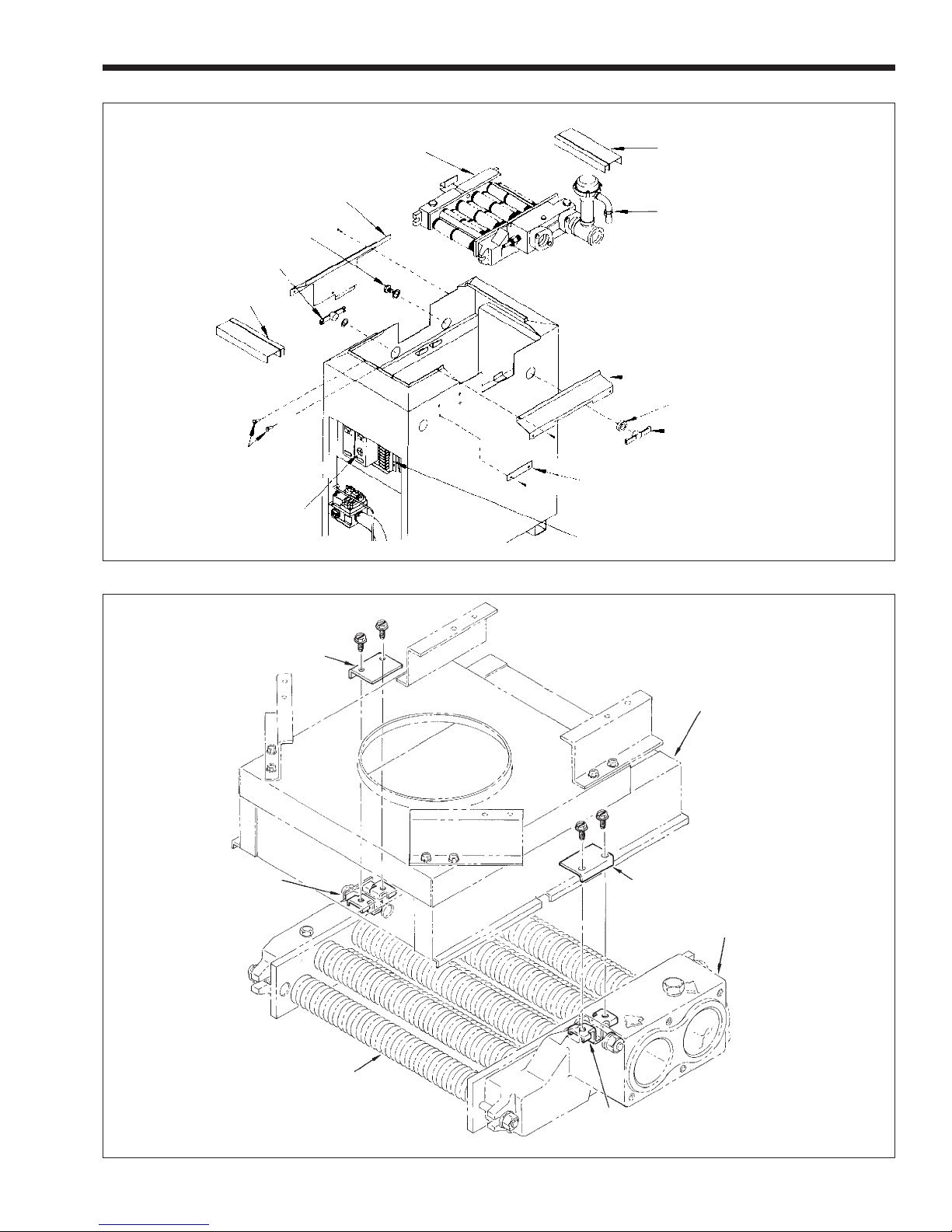
1. Remove the front cover.
2. If there is a vent cap or drafthood installed, they
must be removed before removing the grate top
assembly. On indoor installations (sizes 175-
250), the drafthood switch must be disconnected
at the left side of the heater.
3. If the unit is in the low-profile outdoor
configuration, remove the hex-head screws
(see Figure 15) and lift the grate top assembly
straight up.
4. Remove the screws that fastens the flue collector
holddown clamps and remove the clamps (see
Figure 16).
5. Remove the flue collector assembly by lifting it
out of the chassis.
6. Remove the screws that fastens the gap closures
and put them aside.
7. Remove the three grommets.
8. Remove the drain valves and plug. There is one
hex plug on the left side, near the rear of the
jacket. The drain valves are located on the left
side and right side of the heater (see Figure 9).
9. Remove the four screws that fastens the metal
channels covering the capillary tube on the right
side of the jacket, and lay the channels aside.
10. In the control compartment, find the manual reset
high-limit switch box (see Figure 15) and loosen
the screw on the top to remove the cover.
11. Loosen the screw that fastens the white wire and
remove it from the terminal. Pull it out through
the top of the case and separate the other white
wire from the red wire coming from the fuse
holder. Gently pull the two white wires out of the
control compartment and coil them on top of the
heat exchanger.
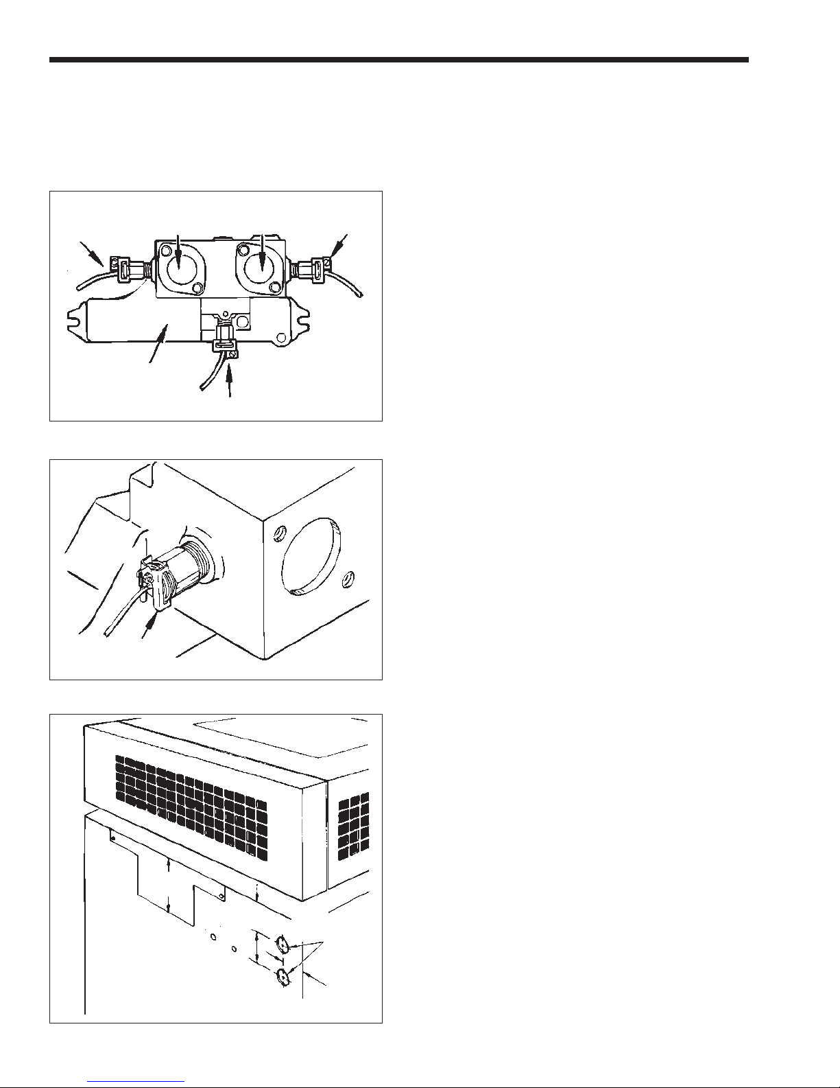
12. A temperature control sensing bulb is located in
the front of the header on the inlet side and a
manual reset hi-limit sensing bulb is located on
the back side of the header on the outlet side (see
Figure 17). Remove these sensing bulbs from the
header. The following steps for removal apply to
all sensing bulbs:
a. If there is more than one capillary tube coming
out of the header, label the capillary tubes.
b. Loosen the screw on the capillary tube
retaining clip, then gently pry the clip apart
until it comes free from the temperature
control (see Figure 18).
c. Pull the sensing bulbs out of the temperature
control.
d. Gently pull the capillary tubes into the control
compartment.
e. Pull the temperature sensing bulb out of the
header, and temporarily route it to the front of
the heater.
Mighty Therm VW - PW Volume Water Heaters
Page 9
GAP CLOSURE
DRAIN PLUG
DRAIN VALVE
REAR TILE
COVER
HEX HEAD
SCREWS
MANUAL RESET
HIGH LIMIT
SWITCH BOX
Figure 15. Heat exchanger reversal.
HEAT EXCHANGER
ASSEMBLY
REAR TILE COVER
FLOW SWITCH
CONDUIT
GAP CLOSURE
GROMMET
METAL CHANNEL
(FOR CAPILLARY TUBE)
TERMINAL STRIP
DRAIN
VALVE
Bracket
Clamp
Flue Collector
Clamp
In/Out Header
Heat Exchanger
Figure 16. Flue collector Holddown Clamps.
Bracket
Page 10
LAARS HEATING SYSTEMS
13. Use a pair of diagonal cutters to cut the plastic
tie around the wire bundle in the control
compartment.
14. On the terminal strip, disconnect the two brown
wires from No. 5 and No. 6 terminals.
2-Stage/
Operating
Controller
Figure 17. Sensory bulb locations.
Retaining
Figure 18. Retaining clip removal.
Attach Capillary
Covers on
Left Side
LEFT
Figure 19. Hole location, left side.
Inlet Outlet
Header
Modulating (if installed)
Clip
3.1 in.
(79mm)
2.4 in.
(61mm)
2.4 in.
(61mm)
High Limit
0.9 in. dia.
(23mm)
(Two holes)
FRONT
1.9 in.
(48mm)
15. Remove the flow switch conduit retaining clip
and the elbow leading into the jacket.
16. Reach inside the control compartment and release
the retaining nut in the upper right corner. The
nut should only be finger-tight.
17. When the conduit is pulled away from the jacket,
pull the two brown wires out of the control
compartment. Coil the conduit and wires on top
of the heat exchanger.
18. Use a chassis punch to put two 7/8 inch (22 mm)
holes in the front left side of the jacket (see
Figure 19).
19. Remove the front and rear tile covers (see
Figure 15).
20. Lift out the heat exchanger assembly, turn it 180
degrees, and reseat the unit in the heater with the
water connections on the left side.
21. Reinstall the front and rear tile covers.
22. Push the capillary tube(s) out through the lower
hole in the left side of the jacket.
23. Install the sensing bulb(s) into the appropriate
temperature control (keep in mind that the
positions of the inlet and outlet have been
reversed. The inlet is now behind the outlet).
24. Fasten the capillary tube(s) by squeezing the
retaining clip together, then tighten the screw.
25. Feed the two brown wires through the top hole
on the left side until the conduit elbow is against
the jacket.
26. Fasten the conduit by sliding the retaining nut
over the two brown wires (inside the control
compartment) then screwing it down finger-tight
on the conduit elbow .
27. Straighten the capillary tubing and fasten it to the
side of the heater under the channel. Use the selftapping screws to fasten the channel to the jacket.
28. Feed the two white wires into the control
compartment. Attach one wire to the terminal in
the manual reset hi-limit switch. If one is not
installed, attach it to terminal No. 1. Connect the
other wire to the red wire attached to the fuse
holder.
29. Attach the two brown wires to terminals No. 5
and 6 on the terminal strip. Keep all wiring away
from surfaces that will get hot during heater
operation.
30. Replace the gap closures and tighten the screws
securely .
31. Replace the three grommets and the cap.
32. Reinstall the drain plug and drain valves.
33. Slip the flue collector assembly back down inside
the enclosure.
 Loading...