

LAARS U.H.E. Installation Manual
y
Installation and Operation Instructions Document 1 1036
TM
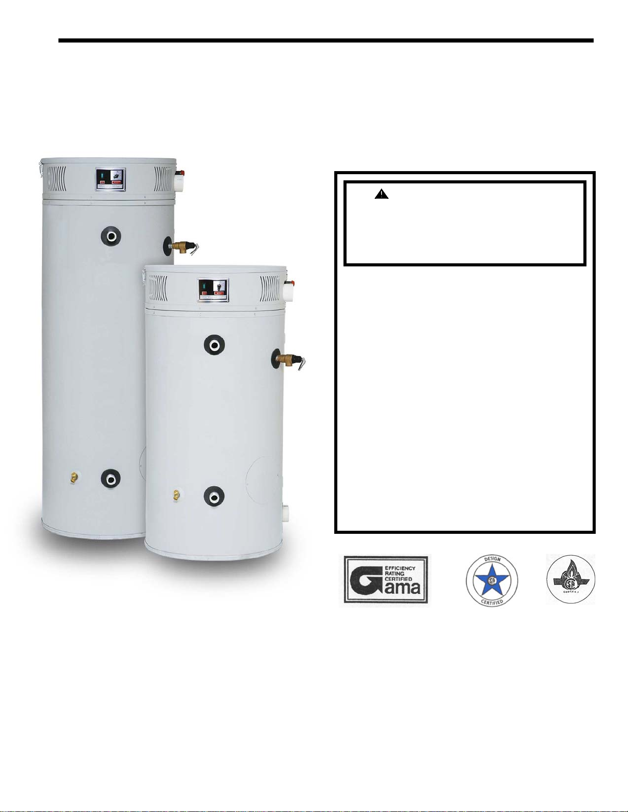
LAARS® U.H.E.
Ultra-High Efficiency Commercial W ater Heaters
WARNING: If the information in
these instructions is not followed
exactly, a fire or explosion may
result causing property damage,
personal injury or death
- Do not store or use gasoline or other
flammable vapors and liquids in the
vicinity of this or any other appliance
- WHAT TO DO IF YOU SMELL GAS
• Do not try to light any appliance.
• Do not touch any electrical switch; do
not use any phone in your building.
• Immediately call your gas supplier
from a neighbor’s phone. Follow the
gas supplier’s instructions.
• If you cannot reach your gas supplier,
call the fire department.
- Installation and service must be
performed b
a qualified installer, service
agency or gas supplier
PLACE THESE INSTRUCTIONS ADJACENT TO HEATER AND NOTIFY OWNER TO KEEP FOR FUTURE REFERENCE
g
p
a
t
t
y
SECTION I: IMPORTANT INFORMATION
READ CAREFULLY
This gas-fired water heater is design certified by CSA International under the American National
Standard, Z21.10.3 (as indicated on the rating plate) and CAN/CGA 4.3-M (as indicated on the rating
plate) available from CSA Standards Association, 178 Rexdale Blvd., Etobicoke, Ontario, Canad
M9W 1R3.
This water heater must be installed in accordance with local codes. In the absence of local codes, i
must be installed in compliance with the National Fuel Gas Code (ANSI Z223.1-Latest Edition), or in
Canada CAN/CGA B149.1 Natural Gas Installation Code (Latest Edition) or CAN/CGA B149.2
Propane Installation Code (Latest Edition).
The following terms are used throughout this manual to bring attention to the presence of hazards a
various risk levels, or to important information concerning product life.
DANGER
Indicates an imminently
hazardous situation, which, if not
avoided, will result in death,
serious injury or substantial
property damage.
WARNING
Indicates a potentially hazardous
situation, which, if not avoided,
could result in death, serious
injury or substantial property
e.
dama
This water heater has a limited warrant
water heater has been installed, maintained and operated in accordance with these instructions.
NOTICE
. The warranty for this water heater is valid only if the
I IMPORTANT INFORMATION................2 VII GAS CONNECTIONS............................33
II SPECIFICATIONS....................................5 VIII ELECTRICAL CONNECTIONS...........35
III GENERAL INFORMATION....................6 IX OPERATING INSTRUCTIONS.............36
IV INSTALLATION INSTRUCTIONS.........9 X MAINTENANCE....................................39
V WATER CONNECTIONS.......................15 XI TROUBLE SHOOTING GUIDE............43
VI VENTING................................................17 XII PARTS LIST...........................................44
TABLE OF CONTENTS
CAUTION
Indicates potentially hazardous
situation, which, if not avoided,
may result in moderate or minor
injury or property damage.
Indicates special instructions on
installation, operation or
maintenance, which are
important but not related to
ersonal i
NOTICE
njury hazards.
2
DANGER
DO NOT store or use gasoline or other flammable, combustible, or corrosive vapors and/or liquids in the vicinity of
this or any other appliance.
DO NOT install any damaged venting system components. If damage is evident then please contact the supplier
where the water heater was purchased or the manufacturer listed on the rating plate for replacement parts.
Use only vent terminals provided or factory authorized terminals for venting this water heater.
This water heater is equipped with an adjustable thermostat to control water temperature. Hot water temperatures
required for automatic dishwasher and laundry use can cause scald burns resulting in serious personal injury and/or
death. The temperature at which injury occurs varies with the person’s age and the time of exposure. The slower
response time of disabled persons increases the hazards to them. NEVER allow small children to use a hot water tap,
or to draw their own bath water. NEVER
Failure to properly install the vent and air intake (if applicable) system could result in property damage, personal
injury, or death
leave a child or disabled person unattended in a bathtub or shower.
WARNING
Improper installation, adjustments, alteration, service or maintenance can cause property damage, personal injury or
loss of life. Failure to follow all instructions in the proper order can cause personal injury or death. Read and
understand all instructions, including all those provided with the appliance before installing, starting-up, operating,
maintaining or servicing this appliance. Keep this manual and literature in legible condition with this water heater
for reference by owner and service technician.
This water heater requires regular maintenance and service to operate safely. Follow the instructions contained in
this manual.
Installation, maintenance, and service must be performed only by a qualified, skilled and knowledgeable installer or
service provider.
Installation is not complete unless a temperature and pressure relief valve is installed into the proper location at the
top of this water heater.
It is the responsibility of the installing contractor to see that all controls are correctly installed and are properly
operating when the installation is complete.
This water heater is suitable for installation on combustible flooring. Do not install water heater on carpeting.
DO NOT operate this water heater without first being certain it is filled with water.
DO NOT tamper with or alter the water heater and/or controls.
DO NOT operate water heater with jumpered or absent controls or safety devices.
DO NOT operate water heater if any external part has been under water. Immediately call a qualified service
agency to inspect the appliance and to replace any part of the control system including gas controls, which has been
under water.
DO NOT attempt to use this water heater with any gas other than the type listed on the rating plate. Do not attempt
to convert this water heater for use with a gas other than the type for which it is equipped. Failure to use the proper
gas can create an unsafe condition resulting in property damage, bodily injury, or death. Consult your local gas
supplier or gas company if there are any questions.
DO NOT operate this water heater if the input rate exceeds the rate shown on the water heater rating plate.
This water heater contains very hot water under high pressure. Do not unscrew any pipe fittings nor attempt to
disconnect any components of this water heater without positively assuring the water is cool and is not under
pressure. Always wear protective clothing and equipment when installing, starting up or servicing this water heater
to prevent scald injuries. Do not rely on the temperature gauges to determine the temperature. Do not touch any
components unless they are cool.
This water heater must be properly vented and connected to an approved vent system in good condition. DO NOT
operate water heater with the absence of an approved vent system. A clean and unobstructed vent system is
necessary to allow noxious fumes that could cause injury or loss of life to vent safely and will contribute toward
maintaining the water heater’s efficiency.
3
WARNING
This water heater needs fresh air for safe operation and must be installed so there are provisions for adequate
combustion and ventilation air. Insufficient air supply will cause a recirculation of combustion products resulting in
contamination that may be hazardous to life. This will result in carboning or sooting of the combustion chamber,
burners, and flue tubes and creates a risk of asphyxiation.
This water heater requires its own separate venting system. DO NOT connect the exhaust vent into an existing vent
pipe or chimney.
Water heater materials of construction, products of combustion and the fuel contain carbon monoxide, nitrogen
oxides, aldehydes and/or other toxic or harmful substances which can cause death or serious injury and which are
known to the state of California to cause cancer, birth defects and other reproductive harm. Always use proper
safety clothing, respirators and equipment when servicing or working nearby this water heater.
Flammable items, pressurized containers or any other potential fire hazardous articles must never be placed on or
adjacent to the water heater. Open containers of flammable material should not be stored or used in the same room
with this water heater.
Insulation blankets are not required for this water heater. This water heater meets or exceeds the ASHRAE/IES
90.1b (latest edition) standards with respect to insulation and standby loss requirements.
Hydrogen gas can be produced in an operating water heater that has not had water drawn from the tank for a long
period of time (generally two weeks or more). Hydrogen gas is extremely flammable. To prevent the possibility of
injury under these conditions, we recommend the hot water faucet to be open for several minutes at the kitchen sink
before you use any electrical appliance, which is connect to the hot water system. If hydrogen is present, there will
be unusual sounds such as air escaping through the pipes as hot water begins to flow. Do not smoke or have open
flame near the faucet at the time it is open.
WARNING
Liquefied petroleum gases/propane gas is heavier than air and will remain at floor level if there is a leak.
Basements, crawl spaces, closets and areas below ground level will serve as pockets for accumulation of leaking
gas. Before lighting, smell all around the appliance area for gas. Be sure to smell next to the floor.
IF YOU SMELL GAS:
• DO NOT try to light any appliance.
• DO NOT touch any electric switch; do not use any telephone in your building.
• Immediately call your gas supplier from a telephone in another building. Follow the gas supplier’s
DO NOT OPERATE THE APPLIANCE UNTIL THE LEAKAGE IS CORRECTED!
instructions.
• If you cannot reach your gas supplier, call the fire department.
4
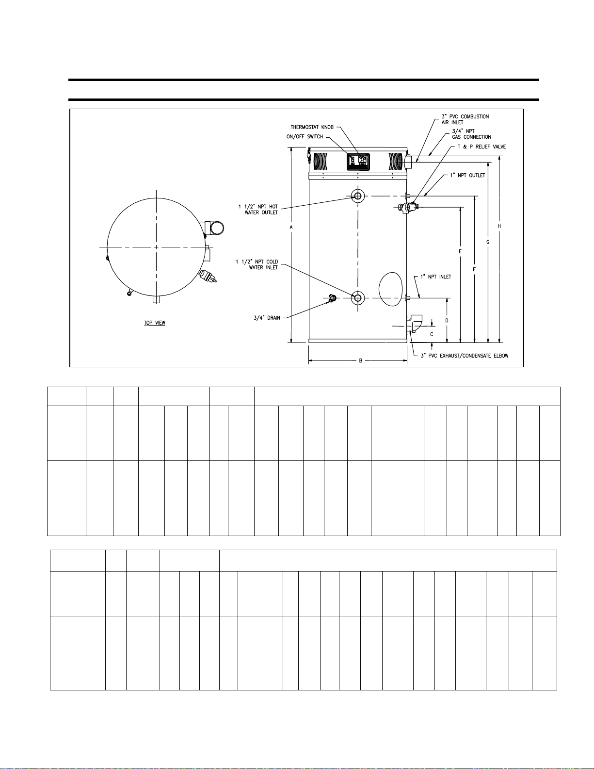
SECTION II: SPECIFICATIONS
Figure 1. Dimensional Layout
1st Hr.
Del.
Storage
Volume
Capacity
Gallons
BTU/h
60 125,000 187 364 145 104 60 95.0 57 28 1/4 5 13 40 42 1/2 52 ½ 53 ½ 1 ½ 1 ¾ ¾ 570
60 150,000 211 423 169 121 60 92.0 57 28 1/4 5 13 40 42 1/2 52 ½ 53 ½ 1 ½ 1 ¾ ¾ 570
60
199,999
100
150,000
100
199,999
100
250,000
100
300,000
100 399,999 516 1,115 446 319 100 92.0 77 5/8 28 1/4 5 13 60 62 1/2 73 1/8 73 1/4 1 1/2 1 1 1 950
Input
Rate
Gal.
100°F
Rise
Recovery GPH
At Degree Rise
At
40°F 100°F 140°F
265
558
250
450
309
597
364
735
405
836
223
180
239
294
335
159
129
171
210
239
Stg.
Cap.
U.S.
Gal.
60
100
100
100
100
Therm.
Eff.
%
91.0
98.1
97.5
96.0
91.0
A
Ht. B Dia.
57
28 1/4
77 5/8
28 1/4
77 5/8
28 1/4
77 5/8
28 1/4
77 5/8
28 1/4
C
Flr to
Vent
Outlet
5
5
5
5
5
Flr to
Inlet
Wtr.
Conn
DIMENSIONS ( INCHES )
D
E
F
Flr to
Fl. to
T&P
Outlet
Valve
Wtr.
Conn
Conn
13
40
60
60
60
60
42 1/2
62 ½
62 ½
62 ½
62 ½
13
13
13
13
G
Fl. to Air
Intake
52 ½
73 1/8
73 1/8
73 1/8
73 1/8
H
Fl. to
Gas
Conn.
53 ½
74 ¾
74 ¾
74 ¾
74 ¾
Front
Wtr.
Conn.
Dia.
1 ½
1 ½
1 ½
1 ½
1 ½
Space
Heating
Conn.
Dia.
1
1
1
1
1
Gas
Conn.
Dia.
¾
¾
¾
¾
¾
Relief
Valve
Open.
DIMENSIONS ( MILLIMETERS)
D
E
F
Flr to
Fl. to
T&P
330
330
330
330
330
330
330
Valve
Conn
1016
1016
1016
1524
1524
1524
1524
Outlet
Wtr.
Conn
1080
1080
1080
1588
1588
1588
1588
G
Fl. to Air
Intake
1334
1334
1334
1857
1857
1857
1857
Fl. to
Gas
Conn.
1359
1359
1359
1899
1899
1899
1899
H
Front
Space
Wtr.
Conn.
Dia.
38
38
38
38
38
38
38
Heating
Conn.
Dia.
25
25
25
25
25
25
25
Gas
Conn.
Dia.
19
19
19
19
19
19
19
Relief
Valve
Open.
19
19
19
19
19
25
25
Storage Volume
Capacity
Gallons
60
60
60
100
100
100
100
100 117.2 1,953 4,221 1,688 1,208 379 92.0 1972 718 127 330 1524 1588 1857 1861 38 25 25 25 431
Input
Rate
KW
36.6
43.9
58.6
43.9
58.6
73.2
87.9
1st Hr.
Del. LPH
at 56°C
Rise
1003
1170
1378
1533
At Degree Rise
22°C 56°C 78°C
708
1378
799
1601
2112
946
1703
2260
2782
3165
Recovery LPH
549
394
640
458
844
602
681
488
905
647
1113
795
1268
905
Stg.
Cap.
Liter
227
227
227
379
379
379
379
Therm.
Eff.
%
95.0
92.0
91.0
98.1
97.5
96.0
91.0
A
Ht.B Dia.
1448
718
1448
718
1448
718
1972
718
1972
718
1972
718
1972
718
C
Flr to
Vent
Outlet
127
127
127
127
127
127
127
Flr to
Inlet
Wtr.
Conn
Shpg.
Wt.
(LBS)
¾
570
¾
900
¾
900
1
900
1
900
Shpg.
Wt.
(KG)
259
259
259
408
408
408
408
Table 1. Specifications
5

SECTION III: GENERAL INFORMATION
FEATURES
This water heater contains the following features:
MAIN POWER ON/OFF SWITCH – The front panel of this water heater has a lighted ON/OFF switch, which is
illuminated when the main power is turned on to indicate power to the water heater.
COMBUSTION SYSTEM –This water heater is equipped with a self-compensating negative pressure pre-mix
combustion system. As the blower operates, air is drawn in through the air intake and into a venturi, which pulls gas
from the gas valve. The gas and air is then mixed in the combustion blower and sent through the transition tube into the
burner. The Hot Surface Ignition System (HSI) then ignites the gas/air fuel mixture to produce flue products
(combustion). The flame sensor signals the ignition module (described below), that a flame is present.
IGNITION MODULE – The ignition module provides the timing for the combustion system. A sequence of operation
(S-OP) is described in “Section IX - Operating Instruction.” As the combustion system progresses through the S-OP,
LED’s illuminate, allowing accurate trouble-shooting should the need arise. If a failure occurs, the system will “blink”
the LED that corresponds to the failure as described in the “Section XI Troubleshooting Guide.”
ADJUSTABLE THERMOSTAT – This water heater is equipped with an adjustable thermostat to control water
temperature. Hot water temperatures required for automatic dishwasher and laundry use can cause scald burns resulting
in serious personal injury and/or death.
The temperature may be adjusted from about 80°F to about 180°F. The thermostat was adjusted to 120°F before the
water heater was shipped from the factory. It is recommended that lower temperatures be used to avoid the risk of
scalding. Refer to the “Warnings” and the section on SCALDING in “Section V - Water Connections.” It is further
recommended, in all cases, that the water temperature be set for the lowest temperature, which satisfies your hot water
needs. This will also provide the most energy efficient operation of the water heater and minimizes scale formation.
Setting the water heater temperature at 120°F will reduce the risk of scalds. Some states require setting the specific
lower temperatures.
The top immersion well of the single bulb controller also contains the high limit (energy cutoff) sensor. The high limit
switch interrupts the main burner gas flow should the water temperature reach approximately 200°F.
Should the high limit switch activate, it must be manually reset. This can be accomplished by turning the main power
on/off switch to the off position and then back to the on position and allowing the water temperature of the tank to drop
below 160°F.
Contact your qualified installing contractor, service provider or manufacturer listed on the rating plate if continued high
limit switch operation occurs.
SERVICE PANEL – The service panel is located behind the service panel access cover, which is located by the
exhaust elbow near the bottom of the water heater. This panel contains a differential pressure switch that monitors the
pressure across the exhaust orifice. A collector high limit switch is used to monitor the ambient temperature between
the first pass collector and the exhaust collector. This is a manually re-settable switch. If this switch continues to trip,
please contact an authorized service agency.
LATCHES – The latches allow easy access for servicing the water heater from the top. Simply remove the two latches
for servicing and re-latch upon completion. No tools are required to obtain access to the top of the water heater.
6
TEMPERATURE AND PRESSURE RELIEF VALVE –
WARNING
Keep clear of the combination temperature and pressure relief valve discharge line outlet. The
discharge may be hot enough to cause scald injury. The water is under pressure and may splash.
For protection against excessive temperatures and pressure, install temperature and pressure protective
equipment required by local codes, but not less than a combination temperature and pressure relief
valve certified by a nationally recognized testing laboratory that maintains periodic inspection of
production of listed equipment or materials as meeting the requirements of the Standard for Relief
Valves and Automatic Gas Shutoff Devices for Hot Water Supply Systems, ANSI Z21.22 and the
Standard CAN1-4.4 Temperature, Pressure, Temperature and Pressure Relief Valves and Vacuum
Relief Valves. The combination temperature and pressure relief valve must be marked with a
maximum set pressure not to exceed the maximum working pressure of the water heater. The
combination temperature and pressure relief valve rating must not be less than the hourly rating of th
water heater
Install the combination temperatu
pu
this
rpose on the water heater.
Note: Some models may already be equipped or supplied with an installed combination temperature
and pressure relief valve. Verify that the combination temperature and pressure relief valve complies
with local codes. If the combination temperature and pressure relief valve does not compl
s,
co
de replace it with one that does. Follow the installation instructions above on this page
Install a discharge line so that water discharged from the combination temperature and pressure relief
valve will exit within six (6) inches (15.2 cm) above, or any distance below the structural floor and
cannot contact any live electrical part. The discharge line is to be installed to allow for complete
drainage of both the combination temperature and pressure relief valve and the discharge line. The
discharge opening must not be subjected to blockage or freezing. DO NOT thread, plug or cap the
discharge line. It is recommended that a minimum clearance of four (4) inches (10.0 cm) be provided
on the side of the w
pressure relief valve.
o
D
o n t place a valve between the combination temperature and pressure relief valve and the
!
tan
k
CONDENSATE DRAIN - The water heater should either be raised several inches above the floor on a concrete slab or
use a low profile condensate pump to allow free drainage of condensate from the elbow drain fitting. This water heater
is a condensing type unit and requires a drain to be located in close proximity to allow the condensate to drain safely.
The condensate drains from the unit at the exhaust elbow located near the bottom of the unit. The preferred connection
to the drain fitting is to use a ¾" PVC elbow sealed with silicone over the outside of the drain outlet and use ¾" PVC for
the drain trap and condensate line to a drain. Use a thick bead of silicone caulk over the outside of the drain outlet
connection before assembling the elbow. This is preferred over using the threaded tap because the larger drain line will
drain more freely and if too much force is applied to the plastic threads, the fitting may crack and cause a leak. Make
sure the condensate drain line slopes down, away from the water heater at least 1/8" per foot toward the drain. The
condensate drain pipe must not be routed through an area subject to below freezing temperatures. The condensate
build-up will block the exhaust outlet, which will cause improper operation. Refer to Figure 2 for the proper connection
of a PVC elbow to the drain outlet and a condensate trap.
ater heater for servicing and maintenance of the combination temperature and
re and pressure relief valve into the opening provided and marked for
y with local
e
7
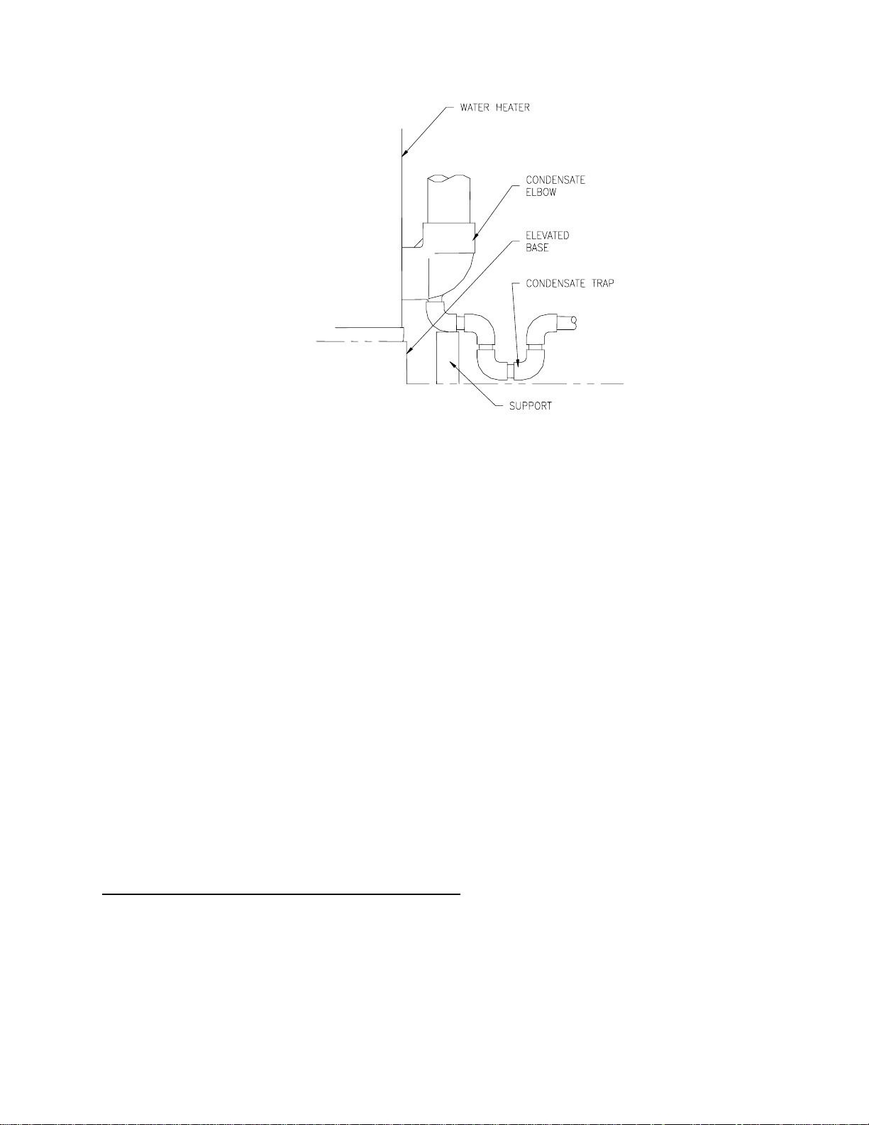
Figure 2. Condensate Elbow With Trap
CLEANOUT – All models are equipped with a cleanout opening to aid in removal of hard water deposits from the
tank bottom. If this water heater operates under hard water conditions, the following should be performed at least every
3 months: Turn off water supply and drain the water heater. Remove the cleanout jacket cover and tank cover. When
cleaning the tank, care must be taken to avoid trying to break deposits loose as this could damage the glass lining and
shorten the life of the water heater. After cleaning, re-install the cleanout tank cover and jacket cover, and refill with
water. Refer to the section, “Section X – Maintenance” in this Installation and Operating Instruction manual for the
procedures for filling and draining the water heater.
SACRIFICIAL ANODES – Four sacrificial anode rods have been installed in the tank head to extend tank life. The
anode rods should be inspected periodically for corrosion and replaced when necessary to prolong tank life. Water
conditions in your area will influence the time interval for inspection and replacement of the anode rods. The use of a
water softener may increase the speed of anode consumption. More frequent inspection of the anodes is needed when
using softened (or phosphate treated) water. Contact the installing contractor, or service provider that installed the
water heater or the manufacturer listed on the rating plate for anode replacement information.
POWERED ANODE SYSTEM (399,999 BTU/HR. MODELS ONLY) – Two powered anodes and one magnesium
anode rod are used on models with input ratings of 399,999 Btu/hr. The powered anode system provides corrosion
protection to the tank by supplying a low voltage current to the titanium anode rods and then periodically comparing
this current with the potential between the anode rod and tank wall to make corrections. The powered anode system is
designed to extend the tank life without requiring anode rod replacement. The powered anode system consists of two
titanium powered anode rods located in the front top of the water heater tank and a powered anode control module
located on the right side of the control panel. More details on the powered anode system are in “Section X –
Maintenance” in this Installation and Operating Instruction Manual.
DISHWASHING MACHINE REQUIREMENTS
All dishwashing machines meeting the National Sanitation Foundation requirements are designed to operate with water
flow pressures between 15 and 25 pounds per square inch. Flow pressures above 25 pounds per square inch, or below
15 pounds per square inch, will result in improperly sanitized dishes.
The National Sanitation Foundation also recommends circulation of 180°F water. Where this is done, the circulation
should be very gentle so that it does not cause any unnecessary turbulence inside the water heater. The circulation
should be just enough to provide 180°F water at the point of take-off to the dishwashing machine. Adjust flow by
means of the valve in the circulation line.
8
g
j
y
n
f
r
K
SECTION IV: INSTALLATION INSTRUCTIONS
INSTALLATION OF THIS WATER HEATER REQUIRES ABILITY EQUIVALENT
TO THAT OF A LICENSED TRADESMAN IN THE FIELD INVOLVED.
PLUMBING, AIR SUPPLY, VENTING, GAS SUPPLY AND ELECTRICAL WOR
ARE REQUIRED.
DO NOT ATTEMPT TO LIGHT ANY GAS APPLIANCE IF YOU ARE NOT
CERTAIN OF THE FOLLOWING:
• Liquefied petroleum gases/propane gas and natural gas have an odorant added by the
gas supplier that aids in detection of the gas.
• Most people recognize this odor as a “sulfur” or “rotten egg” smell.
• Other conditions, such as “odorant fade” can cause the odorant to diminish i
intensity, or “fade”, and not be as readily detectable.
• If you have a diminished sense of smell, or are in any way unsure of the presence o
gas, immediately contact your gas supplier from a telephone in another building.
• Gas detectors are available. Contact your gas supplier or plumbing professional fo
more information.
Liquefied petroleum gases/propane gas is heavier than air and will remain at floor level if there
is a leak. Basements, crawl spaces, closets and areas below ground level will serve as pockets
for accumulation of leaking gas. Before lighting, smell all around the appliance area for gas.
Be sure to smell next to the floor.
IF YOU SMELL GAS:
• Do not try to light any appliance.
• Do not touch any electric switch; do not use any telephone in your building.
• Immediately call your gas supplier from a telephone in another building. Follow the
gas supplier’s instructions.
• If you cannot reach your gas supplier, call the fire department.
DO NOT OPERATE THE APPLIANCE UNTIL THE LEAKAGE IS CORRECTED!
This water heater must be located in an area where leakage of the tank, water line
connections, or the combination temperature and pressure relief valve will not result in
e to the area adjacent to the water heater or to lower floors of the structure. When
dama
such locations cannot be avoided, a suitable drain pan must be installed under the water
heater. The drain pan depth must be suitable for draining and collecting water, and have
a minimum length and width of at least four (4) inches (10.0 cm) measured from the
acket of the water heater. The drain pan, as described above, can be purchased from
our plumbing professional. The drain pan must be piped to an adequate drain. The
piping must be at least ¾ inch (2.0 cm) in diameter and pitched for proper drainage.
WARNING
WARNING
9
UNPACKING
INSPECT SHIPMENT carefully for any signs of damage.
1. All equipment is carefully manufactured, inspected and packed.
2. Any claims for damage or shortage in shipment must be filed immediately with manufacturer and noted on the
Bill of Lading.
3. Remove all venting components from the combustion assembly compartment by removing the latches.
NOTICE
The vent terminals and the condensate elbow that is supplied with this water heater are stored at the top
in the Combustion Assembly Compartment. To access the vent terminals and condensate elbow,
unlatch the top lid and remove parts. Be sure to replace the top and relatch.
LOCATE WATER HEATER in front of final position before removing crate.
1. LOCATE so that venting connections will be short and direct.
2. THIS WATER HEATER IS SUITABLE FOR INSTALLATION ON COMBUSTIBLE FLOOR. Do not
install this water heater on carpeting.
3. FOR BASEMENT INSTALLATION, provide a solid level elevated base such as concrete or other suitable
pad to raise the water heater at least 3” to provide a slope of 1/8” to ¼” per foot for the condensate line to a
suitable drain.
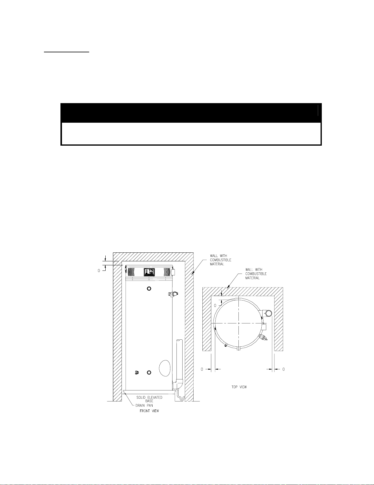
4. Minimum clearance to combustible material is 0” for the Top, Sides, and Rear of this water heater.
However, it is recommended that at least 18” from the Top, 24” from the Front, 4” for the Left Side
and Rear, and 12” from the Right Side Exhaust Elbow of the water heater be provided for servicing.
Clearance for servicing may be reduced down to minimum clearance to combustible material, but service
time and effort may be greatly increased.
Figure 3a. Minimum Clearance To Combustible Material
10
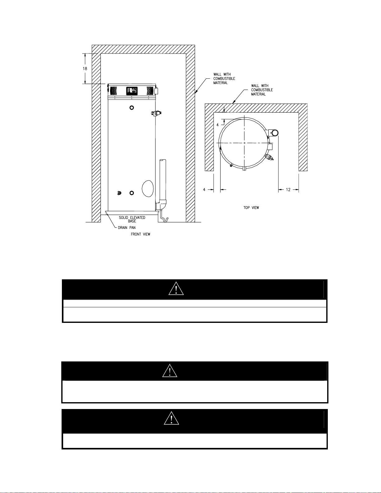
Figure 3b. Recommended Minimum Clearances For Service Access
REMOVE CRATE
1. Remove all banding and pry off crate sides carefully so as not to damage the water heater.
2. Carefully roll/lift the water heater from the crate base.
CAUTION
Do not drop water heater. Do not bump water heater jacket against floor.
Do not bump exhaust vent pipe against crate or other objects. This will damage the heater and cause it
to be inoperable or create nuisance problems.
MOVE WATER HEATER TO PERMANENT POSITION by sliding or walking. Place drain pan underneath water
heater
INSTALL TEMPERATURE AND PRESSURE RELIEF VALVE (if not already installed).
WARNING
Temperature and pressure relief valve discharge piping must be piped near floor to eliminate potential
of severe burns. Do not pipe in any area where freezing could occur. Do not install any shut-off
valves, plugs or caps to the temperature and pressure relief valve or piping.
CAUTION
If the building cold water supply has a back-flow preventer, check valve or water meter with check
valve, provisions for thermal expansion of water in the hot water system must be provided.
11

DANGER
Temperature setting should not exceed safe temperature at fixtures. See water temperature control
warning on page 16. If higher preheat temperatures are necessary to obtain adequate booster output,
add an anti-scald valve for hot water supplied to fixtures.
LOCATION
KEEP APPLIANCE AREA CLEAR AND FREE OF COMBUSTIBLE MATERIALS, GASOLINE AND
OTHER FLAMMABLE VAPORS AND LIQUIDS.
This water heater must be located in an area where the general public does not have access to set temperatures.
AIR REQUIREMENTS
1. Do not obstruct the flow of combustion and ventilating air.
2. For safe operation, adequate air is needed for combustion and ventilation. Sooting may result in serious
damage to the water heater and risk of fire or explosion. It can also create a risk of asphyxiation. Such a
condition often will result in a yellow, luminous burner flame, causing carboning or sooting of the combustion
MECHANICAL EXHAUSTING OF ROOM AIR
UNCONFINED SPACE
CONFINED SPACE
chamber, burner and flue tubes.
1. Where an exhaust fan is installed in the same room with this water heater and combustion air is drawn from
inside the room, sufficient openings for air must be provided in the walls. UNDERSIZED OPENINGS
WILL CAUSE AIR TO BE DRAWN INTO THE ROOM THROUGH THE WATER HEATER’S
VENTING SYSTEM, CAUSING POOR COMBUSTION THAT MAY BE HAZARDOUS TO LIFE.
SOOTING MAY RESULT IN SERIOUS DAMAGE TO THE WATER HEATER AND RISK OF FIRE OR
EXPLOSION, WHICH CAN ALSO CREATE A RISK OF ASPHYXIATION. Refer to local codes and /or
National Fuel Gas Code for proper air opening sizing.
1. In buildings of conventional frame, brick or stone construction, unconfined spaces may provide adequate air
for combustion and ventilation.
2. If the unconfined space is within a building of tight construction (buildings using the following construction:
weather stripping, heavy insulation, caulking, vapor barrier, etc.), air for combustion and ventilation must be
obtained from outdoors. This may be accomplished by piping air directly to the water heater from outside or
providing opening or ducts in the wall. The installation instructions for confined spaces in tightly constructed
buildings must be followed to ensure adequate air supply.
1. When drawing combustion air from inside a conventionally constructed building to a confined space, such a
space shall be provided with two permanent openings.
• The top opening is to be located within twelve (12) inches of the enclosure top and the bottom
opening within twelve (12) inches of the enclosure bottom.
• Each opening shall have a free area of at least one square inch per 1000 Btu/h of the total input of all
appliances in the enclosure, but not less than 100 square inches.
2. If the confined space is within a building of tight construction, air for combustion and ventilation must be
obtained from outdoors. This may be accomplished by piping air directly to the water heater from outside or
providing opening or ducts in the wall. When directly communicating with the outdoors through vertical
ducts, two permanent openings, located in the above manner, shall be provided.
• Each opening shall have a free area of not less than one square inch per 4000 Btu/h of the total input
of all appliances in the enclosure.
• If horizontal ducts are used, each opening shall have a free area of not less than one square inch per
2000 Btu/h of the total input of all appliances in the enclosure.
12
3. If the water heater is installed as a direct vent (outside air piped directly to the water heater), then additional
opening, other than the opening for the air intake, are not required. However, adequate ventilation air must
CHEMICAL VAPOR CORROSION
be provided in all cases to prevent increased room temperature.
Corrosion of the flue ways and vent system will occur if air for combustion contains certain chemical vapors.
Such corrosion may result in poor combustion and create a risk of asphyxiation, as well as reducing the life of the
water heater. Spray can propellants, cleaning solvents, refrigerator and air conditioning refrigerants, swimming
pool chemicals, calcium and sodium chloride, waxes and process chemicals are corrosive. Products of this sort
should not be stored near the water heater or outside by the air intake (if applicable).
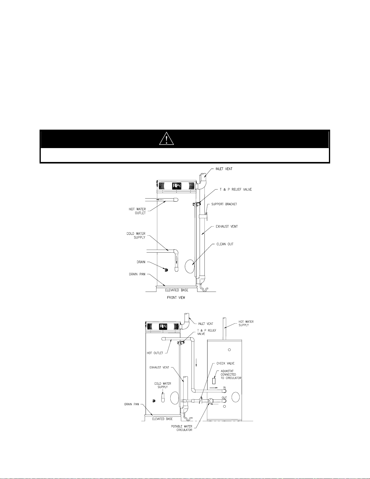
TYPICAL INSTALLATION ILLUSTRATION
CAUTION
If the building cold water supply has a back-flow preventer, check valve or water meter with check valve provisions
for thermal expansion of water in the hot water system must be provided.
Figure 4. Typical Front Inlet Connection
Figure 5. Typical Front Inlet Connect with Storage Heater
13
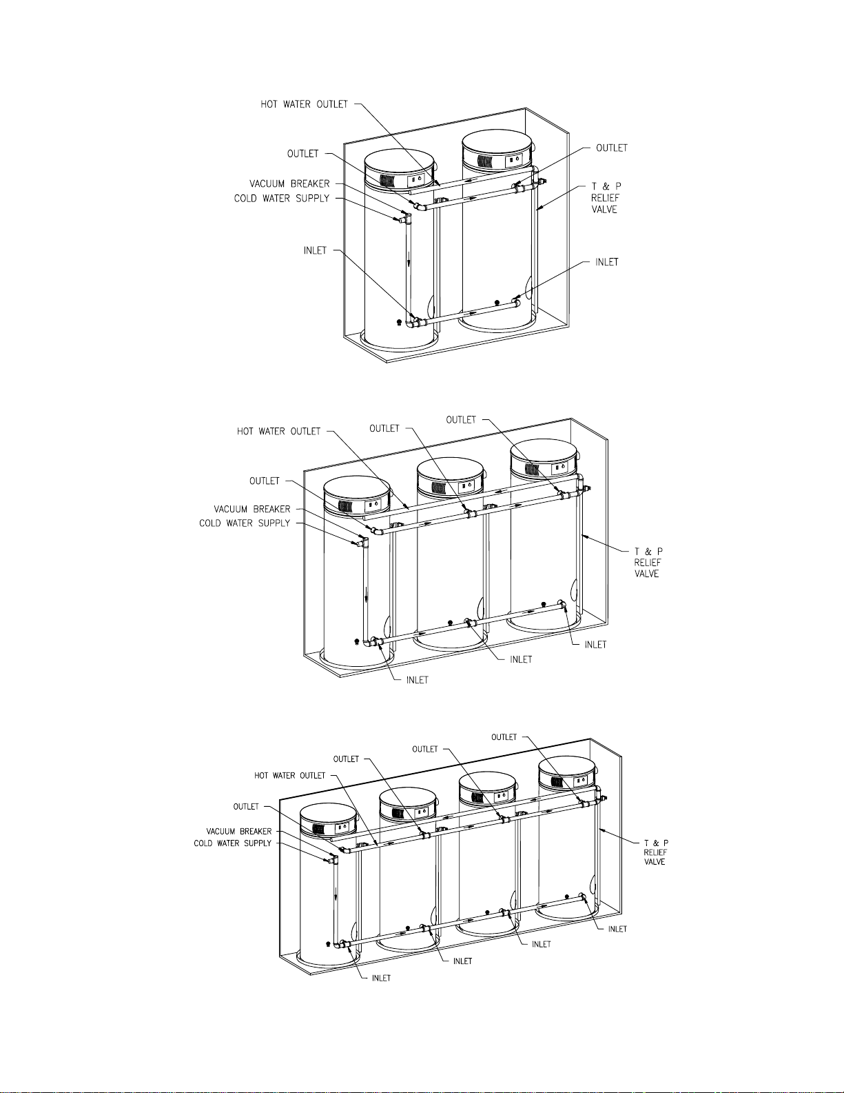
Figure 6. Typical Two Water Heater Connection
Figure 7. Typical Three Water Heater Connection
Figure 8. Typical Four Water Heater Connection
14
SECTION V: WATER CONNECTIONS
WARNING
Failure to install and maintain a new, listed temperature and pressure relief valve will release the manufacturer from
any claim, which might result from excessive temperature and pressures.
Hydrogen gas can be produced in an operating water heater that has not had water drawn from the tank for a long
period of time (generally two weeks or more). HYDROGEN GAS IS EXTREMELY FLAMMABLE. To prevent
the possibility of injury under these conditions, we recommend the hot water faucet to be open for several minutes at
the kitchen sink before you use any electrical appliance, which is connected to the hot water system. If hydrogen is
present, there will be an unusual sound such as air escaping through the pipes as hot water begins to flow. Do not
smoke or have open flame near the faucet at the time it is open.
Keep clear of the combination temperature and pressure relief valve discharge line outlet. The discharge may be hot
enough to cause scald injury. The water is under pressure and may splash.
CAUTION
If sweat fittings are to be used, DO NOT apply heat to the nipples in front or side of the water heater. Sweat the
tubing to the adapter before fitting the adapter to the water connections. It is imperative that heat is not applied to
the nipples containing a plastic liner.
INSTRUCTIONS FOR CONNECTIONS
1. BEFORE PROCEEDING WITH THE INSTALLATION, CLOSE THE MAIN WATER SUPPLY VALVE.
After shutting off the main water supply, open a faucet to relieve the water line pressure to prevent any water
from leaking out of the pipes while making the water connections to the water heater. The COLD water inlet
and HOT water outlet are identified on the water heater. Make the proper plumbing connections between the
SCALDING
This water heater can deliver scalding temperature water at any faucet in the system. Be
careful whenever using hot water to avoid scalding injury. Certain appliances such as
dishwashers and automatic clothes washers may require increased temperature water. By
setting the thermostat on this water heater to obtain the increased temperature water required
by these appliances, you might create the potential for scald injury. To protect against injury,
you should install an ASSE approved mixing valve in the water system. This valve will
reduce point of discharge temperature by mixing cold and hot water in branch supply lines.
Such valves are available from the local plumbing supplier.
water heater and the plumbing system to the house. Install a shut-off valve in the cold water supply line.
2. If this water heater is installed in a closed water supply system, such as the one
having a back-flow preventer in the cold water supply, provisions must be made to
control thermal expansion. DO NOT operate this water heater in a closed system
without provisions for controlling thermal expansion. Warranties do not cover
damages from thermal expansion such as pressure bulges and/or deformities. Your
water supplier or local plumbing inspector should be contacted on how to control this
situation.
3. After installation of the water lines, open the main water supply valve and fill the
water heater. While the water heater is filling, open several hot water faucets to
allow air to escape from the water system. When a steady stream of water flows
through the faucets, close them and check all water connections for possible leaks.
4. Never operate the water heater without first being certain it is filled with water.
15
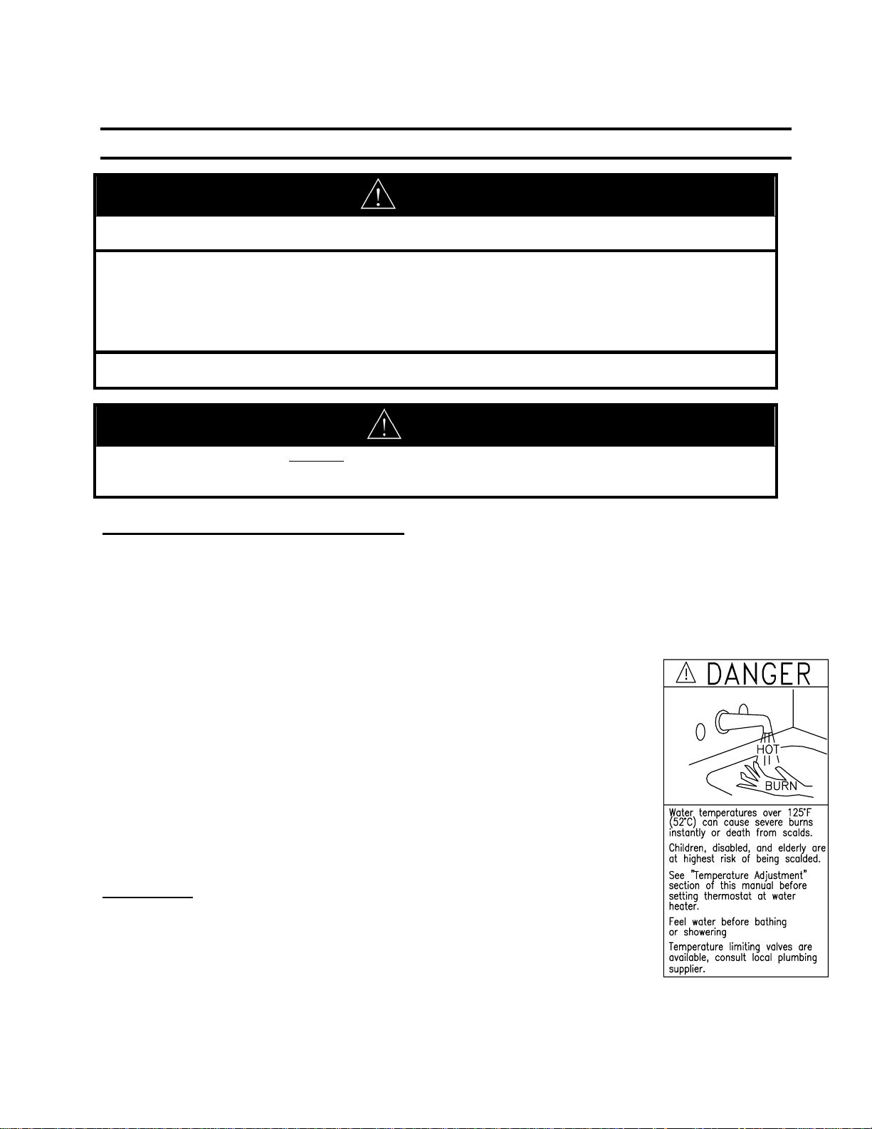
Figure 9. Scald
Warning
 Loading...