

Page 1
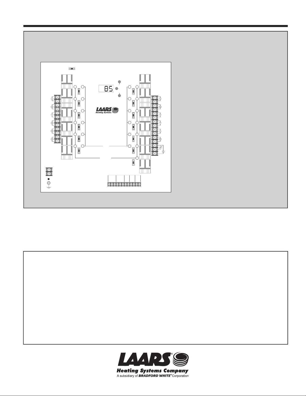
LINE
NEUT
OUTPUT 8
OUTPUT 9
OUTPUT 7
OUTPUT 10
OUTPUT 11
OUTPUT 12
INCREMENT
AUTO
OFF
LEAD STAGE
ROTATION
SELECT
SETTING
UP
DOWN
INPUTS
1 2 345 6 789
10
SAFETY
GROUND
MUST BE
CONNECTED
11
12
Sensor ComShield + SensorCom
DryContact
Only
DryContact
Only
TEMP
SHUTDOWN
/SETBACK
PROVE
/DHW
SYSTEM
Output 7
OFF
AUTO
ON
Output 8
OFF
AUTO
ON
Output 9
OFF
AUTO
ON
Output 10
OFF
AUTO
ON
Output 11
OFF
AUTO
ON
Output 12
OFF
AUTO
ON
OFF
AUTO
ON
OUTPUT 1
OUTPUT 2
OUTPUT 3
OUTPUT 4
OUTPUT 5
OUTPUT 6
Output 1
OFF
AUTO
ON
Output 2
OFF
AUTO
ON
Output 3
OFF
AUTO
ON
Output 4
OFF
AUTO
ON
Output 5
OFF
AUTO
ON
Output 6
OFF
AUTO
ON
System
LEAD
OUTPUT ON
4-20ma
OUTDOOR
SC
Page 2

SC FUNCTION CHART . . . . . . . . . . . . . . . . . . . . . . . . . . . . . . . . . . . . . . . . . . . . . . . . . . . . . . . . . . 3
DIP SWITCH CHART
. . . . . . . . . . . . . . . . . . . . . . . . . . . . . . . . . . . . . . . . . . . . . . . . . . . . . . . . . . . . 4
INSTALLATION .
M
OUNTING THE SC . . . . . . . . . . . . . . . . . . . . . . . . . . . . . . . . . . . . . . . . . . . . . . . . . . . . . . . . . . . . . 5
S
ET THE DIP SWITCHES . . . . . . . . . . . . . . . . . . . . . . . . . . . . . . . . . . . . . . . . . . . . . . . . . . . . . . . . . . 5
W
IRING THE POWER INPUTS . . . . . . . . . . . . . . . . . . . . . . . . . . . . . . . . . . . . . . . . . . . . . . . . . . . . . . . . 5
WIRING THE INPUT TERMINALS . . . . . . . . . . . . . . . . . . . . . . . . . . . . . . . . . . . . . . . . . . . . . . . . . . . . . . 5
W
IRING THE STAGE OUTPUTS . . . . . . . . . . . . . . . . . . . . . . . . . . . . . . . . . . . . . . . . . . . . . . . . . . . . . . . 7
WIRING THE SYSTEM OUTPUT . . . . . . . . . . . . . . . . . . . . . . . . . . . . . . . . . . . . . . . . . . . . . . . . . . . . . . 7
BEFORE POWER UP . . . . . . . . . . . . . . . . . . . . . . . . . . . . . . . . . . . . . . . . . . . . . . . . . . . . . . . . . . . . . 7
P
OWER UP SEQUENCES . . . . . . . . . . . . . . . . . . . . . . . . . . . . . . . . . . . . . . . . . . . . . . . . . . . . . . . . . . 8
ADJUSTING THE CONTROL SETTING
. . . . . . . . . . . . . . . . . . . . . . . . . . . . . . . . . . . . . . . . . . . . 10
SET POINT CONTROL WITH NORMAL SEQUENCING . . . . . . . . . . . . . . . . . . . . . . . . . . . . . . . . . . . . . . . . 10
DIP SWITCH 8 - OFF . . . . . . . . . . . . . . . . . . . . . . . . . . . . . . . . . . . . . . . . . . . . . . . . . . . . . . . . . . . 10
SET POINT CONTROL WITH OSS SEQUENCING . . . . . . . . . . . . . . . . . . . . . . . . . . . . . . . . . . . . . . . . . . 11
O
UTDOOR RESET WITH NORMAL SEQUENCING . . . . . . . . . . . . . . . . . . . . . . . . . . . . . . . . . . . . . . . . . . . 12
OUTDOOR RESET WITH OSS SEQUENCING . . . . . . . . . . . . . . . . . . . . . . . . . . . . . . . . . . . . . . . . . . . . . 13
SC-6 AND SC-12 OUTPUT WIRING
. . . . . . . . . . . . . . . . . . . . . . . . . . . . . . . . . . . . . . . . . . . . . . . 14
WIRING THE STAGE OUTPUTS . . . . . . . . . . . . . . . . . . . . . . . . . . . . . . . . . . . . . . . . . . . . . . . . . . . . . . 14
SC-6P OUTPUT WIRING . . . . . . . . . . . . . . . . . . . . . . . . . . . . . . . . . . . . . . . . . . . . . . . . . . . . . . . . 15
WIRING THE STAGE OUTPUTS . . . . . . . . . . . . . . . . . . . . . . . . . . . . . . . . . . . . . . . . . . . . . . . . . . . . . . 15
SAMPLE WIRING AND PLUMBING DIAGRAMS . . . . . . . . . . . . . . . . . . . . . . . . . . . . . . . . . . . . . 16
OUTPUT RELAY CHARTS . . . . . . . . . . . . . . . . . . . . . . . . . . . . . . . . . . . . . . . . . . . . . . . . . . . . . . .
17
OPERATION . . 18
SET POINT CONTROL SETTINGS . . . . . . . . . . . . . . . . . . . . . . . . . . . . . . . . . . . . . . . . . . . . . . . . . . . . 18
OUTDOOR RESET SETTINGS . . . . . . . . . . . . . . . . . . . . . . . . . . . . . . . . . . . . . . . . . . . . . . . . . . . . . . . 19
NORMAL SEQUENCING SETTINGS . . . . . . . . . . . . . . . . . . . . . . . . . . . . . . . . . . . . . . . . . . . . . . . . . . . . 20
O
VERSIZE SYSTEM SEQUENCING SETTINGS . . . . . . . . . . . . . . . . . . . . . . . . . . . . . . . . . . . . . . . . . . . . 21
SYSTEM OUTPUT SETTINGS . . . . . . . . . . . . . . . . . . . . . . . . . . . . . . . . . . . . . . . . . . . . . . . . . . . . . . . 22
LEAD STAGE . . . . . . . . . . . . . . . . . . . . . . . . . . . . . . . . . . . . . . . . . . . . . . . . . . . . . . . . . . . . . . . . . 22
OUTPUT CONTROLS . . . . . . . . . . . . . . . . . . . . . . . . . . . . . . . . . . . . . . . . . . . . . . . . . . . . . . . . . . . . 23
EXTERNAL SET POINT . . . . . . . . . . . . . . . . . . . . . . . . . . . . . . . . . . . . . . . . . . . . . . . . . . . . . . . . . . . 23
TROUBLESHOOTING . . . . . . . . . . . . . . . . . . . . . . . . . . . . . . . . . . . . . . . . . . . . . . . . . . . . . . . . . . 26
LIMITED WARRANTY . . . . . . . . . . . . . . . . . . . . . . . . . . . . . . . . . . . . . . . . . . . . . . . . . . . . . . . . . . 28
5
Page 3
LINE
NEUT
OUTPUT 8
OUTPUT 9
OUTPUT 7
OUTPUT 10
OUTPUT 11
OUTPUT 12
INCREMENT
AUTO
OFF
LEAD STAGE
ROTATION
SELECT
SETTING
UP
DOWN
INPUTS
1 2 345 6 789
10
SAFETY
GROUND
MUST BE
CONNECTED
11
12
Sensor Com Shield + Sensor Com
DryContact
Only
DryContact
Only
TEMP
SHUTDOWN
/SETBACK
PROVE
/DHW
SYSTEM
Output 7
OFF
AUTO
ON
Output 8
OFF
AUTO
ON
Output 9
OFF
AUTO
ON
Output 10
OFF
AUTO
ON
Output 11
OFF
AUTO
ON
Output 12
OFF
AUTO
ON
OFF
AUTO
ON
OUTPUT 1
OUTPUT 2
OUTPUT 3
OUTPUT 4
OUTPUT 5
OUTPUT 6
Output 1
OFF
AUTO
ON
Output 2
OFF
AUTO
ON
Output 3
OFF
AUTO
ON
Output 4
OFF
AUTO
ON
Output 5
OFF
AUTO
ON
Output 6
OFF
AUTO
ON
System
LEAD
OUTPUT ON
4-20 ma
OUTDOOR
SC
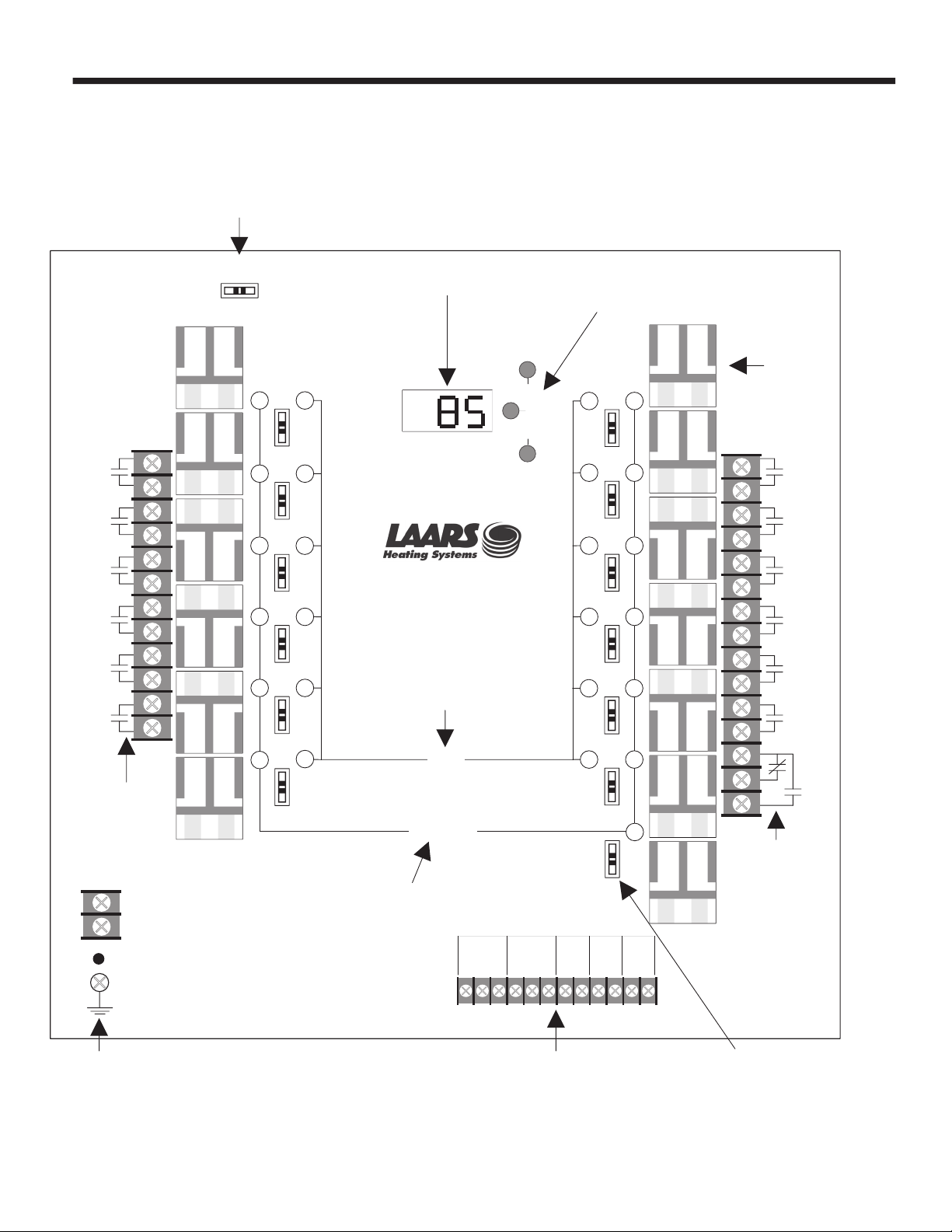
Digital display reads
sensor value constantly
Install a relay for
each output stage
which will be active
Use these three buttons
to adjust the settings
In AUTO, the lead stage will automatically
rotate among the active outputs. Press to
INCREMENT for manual rotation.
Each Stage
Output has
one set of
N.O. contacts
The green LEAD stage
light indicates which
stage will be activated
first on a system call
The red OUTPUT lights
indicate when the relays
are energized and the
N.O. contacts are
continuous.
The System
Output is
SPDT
Each output can be switched
ON, AUTO, or OFF. In AUTO,
the output will be controlled
based on system requirements.
120 VAC Power Input
GND must be connected
Sensor, Shutdown/Setback,
Prove/DHW, and Outdoor
input terminals
Page 4
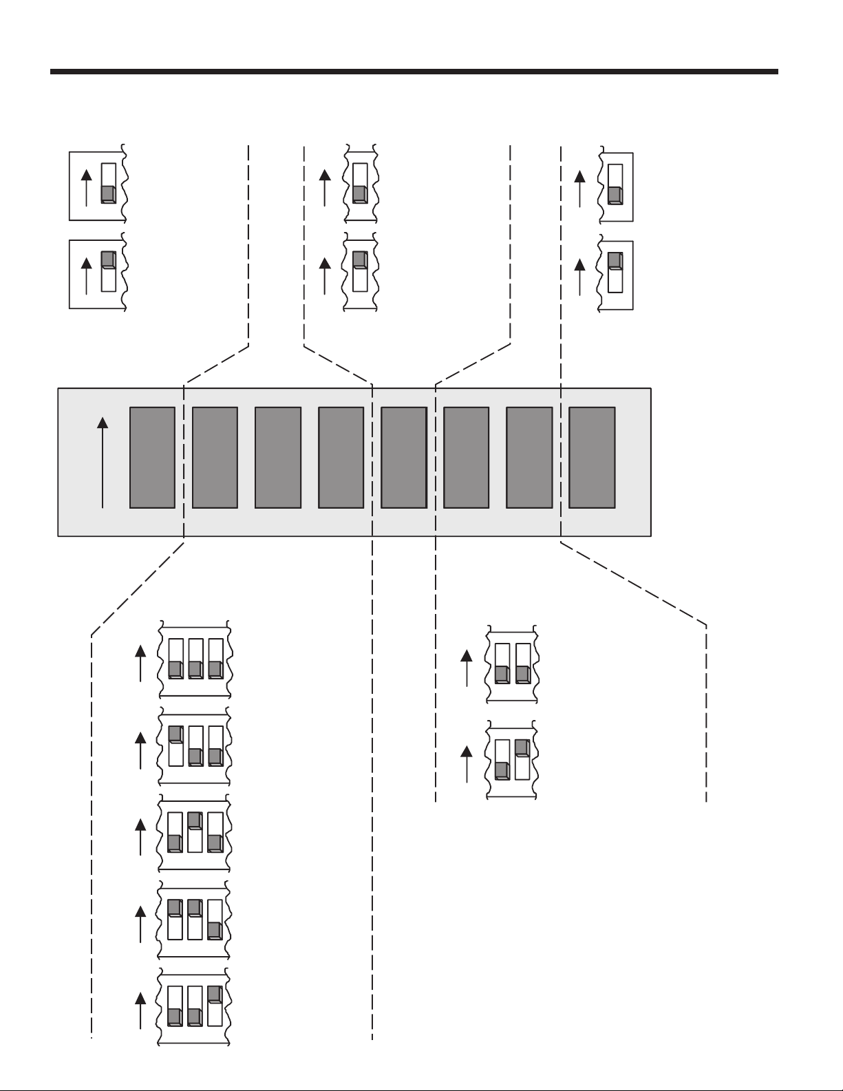
1 2 3 4 5 6 7 8
ON
Switch 1
System Output
Switch 5
Rotation
Switches 6 and 7
Input Type
5
First On/Last Off
Lead stage rotates
every 24 hours
5
First On/First Off
First stage on is
the first stage
turned off
Temperature
6 7
External Set Point
Available for temperature
systems only, 4-20mA
signal changes Set Point
6 7
ON
ON
ON
ON
Switch 8
Set Point or Reset
8
Set Point
Set Point control
for temperature
8
Outdoor Reset
Hydronic heating
control with
outdoor reset
ON
ON
1
System Pump
SYSTEM relay is on
based on outside
temp, Shutdown,
and DHW priority
1
Combustion Air
Damper/Prove
SYSTEM relay is
on when any
OUTPUT is on
ON
ON
Switches 2, 3, and 4
Stage Type
2Stage Lo/Lo/Hi/Hi
On load increase
sequence on Lo
stages first, then Hi
stages
2
On/Off Stages
Each stage is
either on or off
2 Stage Lo/Hi
On load increase
sequence Lo to Hi
then next Lo to Hi
3 4
2 3 4
2
3 Stages
On load increase
sequence Lo, Mid,
Hi
3 4
2 3 4
4 Stages
On load increase
sequence Lo,
LoMid, HiMid, Hi
2 3 4
ON
ON
ON
ON
ON
ON
Page 5
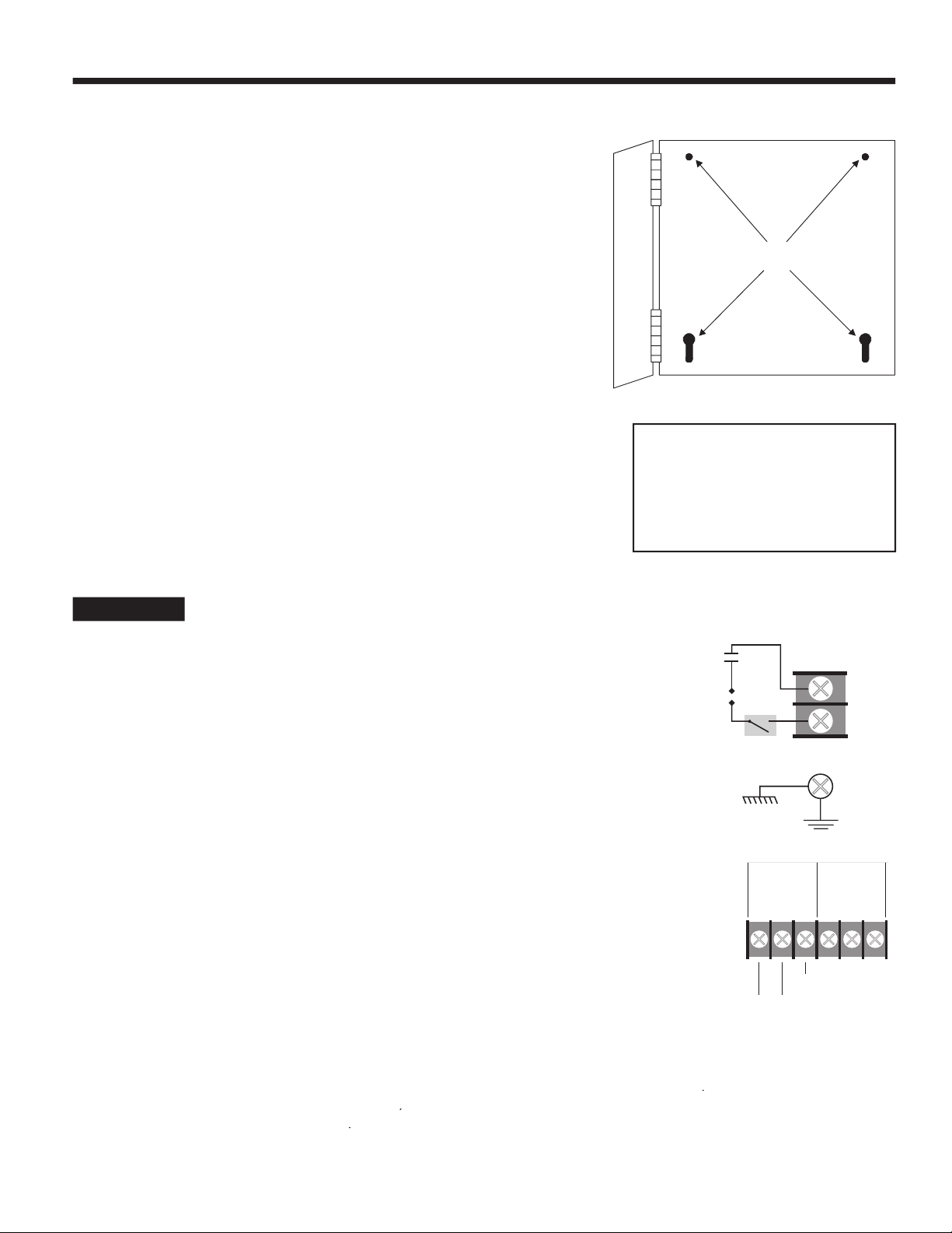
temperature is from 20 to 120°F.
the enclosure.
the metal front panel).
- System relay output type - Combustion Air Damper, or System Pump operation
- Stage type - On/Off, Lo/Hi, 3 Stage or 4 Stage
- Rotation Sequence - First On/Last Off or First On/First Off
- Input type - Temperature or External Set Point
- Operation - Set Point or Outdoor Reset
IMPORTANT
The dip switches must be set correctly. Carefully, check the details of the installation and
WIRING THE POWER INPUTS
voltage wiring.
LINE.
NEUT.
WIRING THE INPUT TERMINALS
and
NOT
be installed in between boiler connections to header. If the sensor does not
register the output of all the stages, it will not be able to Sequence properly.
2 COM
Mounting Holes
LINE
NEUT
Surge
Suppressor
Power Switch
Ground
Line
Neut
INPUTS
1 2 3
4
5 6
Sensor Com Shield + Sensor Com
TEMP PRES 4-20 ma
Shield
To Temperature Sensor
in Common Header
Page 6
6
and dip switch 7 must be
monitor the 4-20mA input to change the set point. (See wiring sensor on pg. 3) Also, see pg. 23 for
EMS programming parameters.
and
SETBACK
setting to 0 the
SHUTDOWN
feature is enabled by
were on will remain on until the System Delay is over, then they will also turn off.
SHUTDOWN
feature can be used whenever it is desirable to turn off the SC from a remote
SETBACK
is enabled by adjusting control
SETBACK
setting to a value higher
than 0 and closing a dry contact wired to terminals 7 and 8, the SC will immediately reduce the
temperature of the circulating hot water by the
SETBACK
setting amount (see pg. 20 to
SETBACK)
SHUTDOWN/SETBACK
signal must be a dry contact only to terminals 7 and 8. No voltage can be
placed across the
SHUTDOWN/SETBACK
terminals.
and
) and Domestic Hot Water (
).
PROVE
feature is used to check system components’ operation before activating any stages. See
pg. 24 for typical applications.
PROVE
input terminals are open, the SC will enable only the System Output relay. All Stage
PROVE
input is open.
DHW
) input is enabled by closing a dry contact, the Calculated water
temperature or the Set Point will change to 200°F and the decimal point on the left-most digit on the
DHW
input will take priority over the outdoor reset function or the Outdoor Cutoff temperature.
Regardless of outdoor temperature, when the
DHW
input is closed, the SC will Sequence stages to
hold 200°F.
NO
external conditions must be met before Stage Output is activated and terminals
and
are not used for Domestic Hot
Water (see pg. 25),
DO NOT
remove the factory installed jumper across the
PROVE/DHW
terminals.
PROVE/DHW
signal must be a dry contact only to terminals 9 and 10. No voltage can be placed across the
PROVE/DHW
terminals.
IMPORTANT
input terminals must be
and
).
). If it is installed, it will act as an Outdoor
windows, exhaust fans, vents, or other possible heat sources.
and 12.
Note that both sensor shields will be connected
to terminal 3.
Dry Contact
Prove or Domestic
Hot Water Signal
INPUTS
5 6 7
8910
11
Sensor Com
DryContact
Only
DryContact
Only
SHUTDOWN
/SETBACK
PROVE
/DHW
OUTD
4-20 ma
INPUTS
5 6 7
89101112
Sensor Com
DryContact
Only
DryContact
Only
SHUTDOWN
/SETBACK
PROVE
/DHW
4-20 ma
OUTDOOR
To Outdoor Sensor
In Shade
Shield
2 3
4
Com Shield +
TEMP
4
5 6
+ Sensor Com
4-20 ma
SC Source Current
24VDC Excitation Voltage
(-) Input
(+) Signal
INPUTS
5 6 7
8
9
Sensor Com
DryContact
Only
DryContact
SHUTDOWN
/SETBACK
PROVE
4
+
4-20 ma
Dry Contact
Shutdown and
Setback Signal
4
5 6
+ Sensor Com
4-20 ma
EMS Sourcing Current
(-) Input
(+) Signal
Page 7
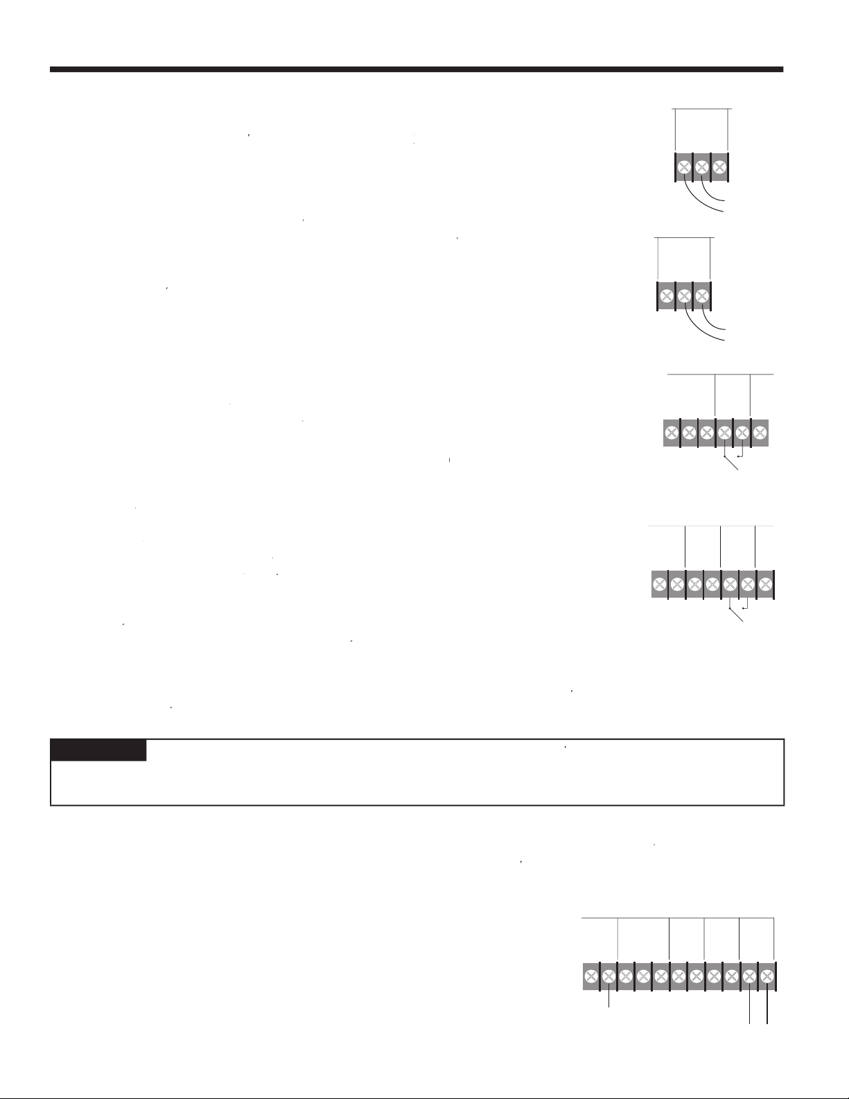
WIRING THE STAGE OUTPUTS
WIRING THE SYSTEM OUTPUT
- If there is no call for stage output, the System relay is off
- On a call for stage output, the System relay is energized
- When the
PROVE
input is made, the lead stage is energized
- The System relay remains energized as long as any stage is active
- When the last stage turns off, the System relay remains energized for the period of
time set by the System Delay (see pg. 22)
- Then the System relay is turned off.
PROVE
inputs. The
PROVE
input can be used in a
and the Shutdown is not
- The System relay will be energized when any stage is active
- After the last stage is turned off, the System relay will remain energized for the period of time set by the System Delay (see pg.
22) and then turn off.
- When the outdoor temperature below the Outdoor Cutoff + 2°F (
+ 2°F), the
- Otherwise, the System relay will be off above
+ 2°F (after the System Delay
has expired).• When the control is set
- The System relay will be off for an adjustable period of time set by the DHW Priority Time
- After the Priority Time has elapsed, when the outdoor temperature is below the Outdoor Cutoff + 2°F (
+ 2°F) setting, the
- When the outdoor temperature is 2°F above the Outdoor Cutoff (
+
2°F), the System relay will be off at all times.
switch in the
AUTO
position.
switch in the
position.
LEAD STAGE
switch in the
AUTO
position for automatic rotation.
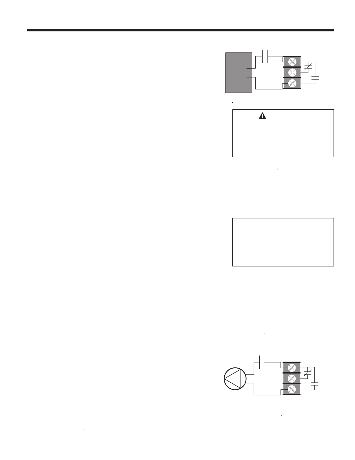
SYSTEM
C.
N.C.
N.O.
Combustion
Air Damper
Line
Neut
SYSTEM
C.
N.C.
N.O.
System Pump
Line
Neut
WARNING
Page 8

the parameters are correct, there is no need to make any adjustments.
reapply power.
the SC will operate in Fahrenheit. If the display shows
then the SC will operate in Celsius.
button to increase the value,
DOWN
button to decrease the value.
and
(see pg. 25).
the Input terminals
and
will function in the Prove mode. If the display shows
then the same
terminals will function in the DHW mode.
button to increase the value, or
the
DOWN
button to decrease the value.
will fl ash.
Normal
or PID type Sequencing mode provides the most stable operation. Stages are turned on or off
based on the rate of change of the system temperature and the impact a stage has on that rate.
) Sequencing
mode that brings on stages proportionally, based on how high above or far below the Set Point the current system temperature is.
For more details, see pg. 21.
(Normal) then the SC will Sequence in the PID type mode. If the display shows
then SC will
around the Set Point
button to increase the value, or the
DOWN
button to decrease the value.
will fl ash. This completes the startup Sequence and the SC will display the sensor temperature.
the SC will operate in Fahrenheit. If the display shows
then the SC will operate in Celsius.
button to increase the value,
DOWN
button to decrease the value.
Minimum Water Temperature
INCREMENT
AUTO
OFF
LEAD STAGE
ROTATION
For Automatic Lead
Stage Rotation
Output
OFF
AUTO
ON
For Non-Active
Stages
For Stages Which are
to be Part of the
Automatic Sequence
Page 9

button to increase the
value, or the
DOWN
button to decrease the value.
will fl ash.
and
(see pg. 25).
the Input terminals
and
will function in the Prove mode. If the display shows
then the same
terminals will function in the DHW mode.
button to increase the value, or
the
DOWN
button to decrease the value.
will fl ash.
based on the rate of change of the system temperature and the impact a stage has on that rate.
Sequencing mode
that brings on stages proportionally, based on how high above or far below the Set Point the current system temperature is. For
more details, (see pg. 21).
then the SC will Sequence in the PID type mode. If the display shows
then SC will
button to increase the value, or the
DOWN
button to decrease the value.
will fl ash. This completes the startup Sequence and the SC will display the sensor temperature.
Page 10

ADJUSTING THE CONTROL SETTING
SELECT SETTING
button.
Set Point Control with Normal Sequencing Temperature or External Set Point pg. 10
Set Point Control with Oversize System Sequencing Temperature or External Set Point pg. 11
Outdoor Reset Control with Normal Sequencing pg. 12
Outdoor Reset Control with Oversize System Sequencing pg. 13
Press SELECT
SELECT
SETTING
UP
DOWN
Press and
Hold to
Adjust
Press to Scroll
Through Control
Settings
Control Settings
Display
Button
Once
Twice
♦
♦♦
3 Times
3 or 4 Times
4 or 5 Times
5 or 6 Times
6 or 7 Times
7 or 8 Times
7 or more Times
8 or more Times
8 or more Times
♦♦
♦♦
♦♦
SET POINT CONTROL WITH NORMAL SEQUENCING
Dip Switch 8 - OFF
DISPLAY Press and hold either the UP or DOWN button to adjust
The Set Point is the temperature which the SC will sequence stages to hold. Note that if you are
using the External Set Point, you will not be able to change the Set Point unless you adjust the 4-
Set Point
Outdoor Temp
Outdoor Cutoff
Reaction Time
System Delay
Purge Time
Boiler runtime
Program Offset
Last Stage Hold
Setback
DHW Priority Time
20mA input. The Set Point is adjustable between -30
This is the outdoor sensor temperature value.
Available only when the outdoor sensor is installed. When the outdoor temperature falls below the
Outdoor Cutoff value, the SC will activate stages for heat. The Outdoor Cutoff can be set ON or OFF
and from 40 to 100°F. Default is 60°F.
The Reaction Time controls the minimum run time for a stage (1/2 the Reaction Time). Also, it controls how long should a stage run before it activates/subtracts another stage. It is adjustable from half
a minute (0.5) to 8.0 minutes. Default is 2 minutes.
The System Delay controls how long the System relay will remain energized after the last Output has
been turned off or the outdoor temperature rises above the Starter. The System Delay is adjustable
from 0 to 30 minutes. Default is 0.
The Purge Time should be set to the length of the unit’s purge cycle. The Purge Time will apply
when any ON/OFF unit is activated. On multiple stage units, the Purge Time will only apply to the Lo
stages. The Purge Time is adjustable from 0.0 to 10.0 minutes.
This is the minimum amount of time any boiler will run after the Purge cycle has been completed. This
timer does not apply when only one stage is running, the Last Stage Hold LSH applies in that case.
The Boiler Runtime is adjustable between 0 to 60 minutes. Default is 0.
The Programmed Offset fi ne tunes the External Set Point. With a known 4mA input, the offset can be
set to make the External Set Point 110°F. The Program Offset is adjustable between -10
Default is 0°F.
To prevent short cycling of the last stage in low load conditions, the system temperature can exceed
the Set Point by the amount selected by the Last Stage Hold before the last stage is turned off. The
Last Stage Hold is adjustable between 0°F to 20°F. Default is 10°F.
The Setback adjusts the number of degrees the Set Point water temperature will be reduced when
Input terminals 7 and 8 are closed. If the Setback is set to 0, then the system will Shutdown on a
closure. The Setback is adjustable from 0°F to 40°F. Default is 0°F.
Only available when the System Output is set to System Pump (dip switch 1 is ON and dip switch 6 is
OFF ) This setting adjusts the amount of time the System relay output will remain off during a DHW
call. If the DHW call is not satisfi ed before the DHW priority time has elapsed, the System relay will
energize to provide heat. The DHW Priority is adjustable from 0 to 4 hours in half hour increments.
Default is 0.
°F to 250°F. Default is 70°F.
Default is 0.
°F to +10°F.
8 or more Times
♦ Actual temperature values are not adjustable
♦♦ May not be available, depending on status of the outdoor sensor and dip switches.
♦
Default
The SC returns to the default display of system water temperature.
Page 11

Press SELECT
Button
Once
SET POINT CONTROL WITH OSS SEQUENCING
Dip Switch 8 - OFF
DISPLAY Press and hold either the UP or DOWN button to adjust
The Set Point is the temperature which the SC will sequence stages to hold. Note that if you are
Set Point
using the External Set Point, you will not be able to change the Set Point unless you adjust the 420mA input. The Set Point is adjustable between -30
°F to 250°F. Default is 70°F.
♦
Twice
3 Times
♦♦
3 or 4 Time
4 or 5 Times
4 or more Times
5 or more Times
5 or more Times
5 or more Times
Outdoor Temp
Outdoor Cutoff
System Delay
♦♦
Program Offset
Throttling Range
♦♦
Setback
♦♦
DHW Priority Time
♦
Default
This is the outdoor sensor temperature value.
Available only when the outdoor sensor is installed. When the outdoor temperature falls below the
Outdoor Cutoff value, the SC will activate stages for heat. The Outdoor Cutoff can be set ON or OFF
and from 40 to 100°F.
The System Delay controls how long the System relay will remain energized after the last Output has
been turned off or the outdoor temperature rises above the Starter. The System Delay is adjustable
from 0 to 30 minutes. Default is 0.
The Programmed Offset fi ne tunes the Pressure input or the External Set Point. With a known 4mA
input, the offset can be set to make the External Set Point 110°F. The Program Offset is adjustable
between -10°F to +10°F. Default is 0°F.
The throttling range sets the number of degrees or psi above and below the Set Point where stages
will be turned on or off. The Throttle Range is adjustable from 1
24 for details.
The Setback adjusts the number of degrees the Set Point water temperature will be reduced when
Input terminals 7 and 8 are closed. If the Setback is set to 0, then the system will Shutdown on a
closure. The Setback is adjustable from 0°F to 40°F. Default is 0°F.
Only available when the System Output is set to System Pump (dip switch 1 is ON and dip switch 6 is
OFF ) This setting adjusts the amount of time the System relay output will remain off during a DHW
call. If the DHW call is not satisfi ed before the DHW priority time has elapsed, the System relay will
energize to provide heat. The DHW Priority is adjustable from 0 to 4 hours in half hour increments.
Default is 0.
The SC returns to the default display of system water temperature.
Default is 60°F.
♦ Actual temperature values are not adjustable
♦♦ May not be available, depending on status of the outdoor sensor and dip switches.
°F to 20°F. Default is 5°F. See page
Page 12

Press SELECT
Button
Once♦
OUTDOOR RESET WITH NORMAL SEQUENCING
Dip Switch 6 and 7 - OFF and 8 - ON
DISPLAY Press and hold either the UP or DOWN button to adjust
This is the water temperature the SC will stage outputs to hold. It is based on outdoor temperature,
Calculated
Reset Ratio, and the Offset value. If OFF is shown, there is no call for heat. If PrF is shown, the SC
is waiting for a Prove signal before activating stages.
Twice
3 Times
4 Times
5 Times
6 Times
7 Times
8 Times
9 Times
10 Times
11 Times
12 Times
♦
Outdoor Temp
Outdoor Cutoff
Reset Ratio
Offset
Reaction Time
System Delay
Purge Time
Boiler runtime
Last Stage Hold
Setback
♦♦
DHW Priority Time
This is the outdoor sensor temperature value.
When the outdoor temperature falls below the Outdoor Cutoff value, the SC will give heat. When the
outdoor temperature is above the Outdoor Cutoff, the Calculated value will be OFF and no stages will
be activated except on a DHW call. The Outdoor Cutoff can be set ON or OFF and from 40 to 100°F.
Default is 60°F.
The Reset Ratio controls the amount of heat which enters the heating system based on the outdoor
temperature. A higher numbered Reset Ratio will result in a higher Calculated water temperature.
See the chart on pg. 19 for the reset curves. The Reset Ratio is adjustable from 1 to 12. Default is 7.
The Offset moves the reset curves vertically up or down. For example, changing the offset from 0 to
-10 will decrease the water temperature 10°F regardless of outdoor temperature or the reset curve
selected. The Offset is adjustable from -40
The Reaction Time controls the minimum run time for a stage (1/2 the Reaction Time). Also, it controls how long should a stage run before it activates/subtracts another stage. It is adjustable from half
a minute (0.5) to 8.0 minutes. Default is 2 minutes.
The System Delay controls how long the System relay will remain energized after the last Output has
been turned off or the outdoor temperature rises above the Starter. The System Delay is adjustable
from 0 to 30 minutes.
The Purge Time should be set to the length of the unit’s purge cycle. The Purge Time will apply
when any ON/OFF unit is activated. On multiple stage units, the Purge Time will only apply to the Lo
stages. The Purge Time is adjustable from 0.0 to 10.0 minutes.
This is the minimum amount of time any boiler will run after the Purge cycle has been completed. This
timer does not apply when only one stage is running, the Last Stage Hold LSH applies in that case.
The Boiler Runtime is adjustable between 0 to 60 minutes. Default is 0.
To prevent short cycling of the last stage in low load conditions, the system temperature can exceed
the Calculated water Temperature by the amount selected by the Last Stage Hold before the last
stage is turned off. The Last Stage Hold is adjustable between 0
The Setback adjusts the number of degrees the Set Point water temperature will be reduced when
Input terminals 7 and 8 are closed. If the Setback is set to 0, then the system will Shutdown on a
closure. The Setback is adjustable from 0°F to 40°F. Default is 0°F.
Only available when the System Output is set to System Pump (dip switch 1 is ON and dip switch 6 is
OFF ) This setting adjusts the amount of time the System relay output will remain off during a DHW
call. If the DHW call is not satisfi ed before the DHW priority time has elapsed, the System relay will
energize to provide heat. The DHW Priority is adjustable from 0 to 4 hours in half hour increments.
Default is 0.
°F to 40°F. Default is 0°F.
Default is 0.
°F to 20°F. Default is 10°F.
12 to 13 Times
♦
Default
The SC returns to the default display of system water temperature.
♦ Actual temperature values are not adjustable
♦♦ May not be available, depending on status of the outdoor sensor and dip switches.
Page 13

Press SELECT
Button
Once♦
OUTDOOR RESET WITH OSS SEQUENCING
Dip Switch 6 and 7 - OFF and 8 - ON
DISPLAY Press and hold either the UP or DOWN button to adjust
This is the water temperature the SC will stage outputs to hold. It is based on outdoor temperature,
Calculated
Reset Ratio, and the Offset value. If OFF is shown, there is no call for heat. If PrF is shown, the SC
is waiting for a Prove signal before activating stages.
Twice
3 Times
4 Times
5 Times
6 Times
7 Times
8 Times
9 Times
♦
Outdoor Temp
Outdoor Cutoff
Reset Ratio
Offset
System Delay
Throttling Range
Setback
♦♦
DHW Priority Time
This is the outdoor sensor temperature value.
When the outdoor temperature falls below the Outdoor Cutoff value, the SC will give heat. When the
outdoor temperature is above the Outdoor Cutoff, the Calculated value will be OFF and no stages will
be activated except on a DHW call. The Outdoor Cutoff can be set ON or OFF and from 40 to 100°F.
Default is 60°F.
The Reset Ratio controls the amount of heat which enters the heating system based on the outdoor
temperature. A higher numbered Reset Ratio will result in a higher Calculated water temperature.
See the chart on pg. 19 for the reset curves. The Reset Ratio is adjustable from 1 to 12.
The Offset moves the reset curves vertically up or down. For example, changing the offset from 0 to
-10 will decrease the water temperature 10°F regardless of outdoor temperature or the reset curve
selected. The Offset is adjustable from -40
The System Delay controls how long the System relay will remain energized after the last Output has
been turned off or the outdoor temperature rises above the Starter. The System Delay is adjustable
from 0 to 30 minutes.
The throttling range sets the number of degrees or psi above and below the Set Point where stages
will be turned on or off. The Throttle Range is adjustable from 1°F to 20°F. Default is 5°F. See page 21
for details.
The Setback adjusts the number of degrees the Set Point water temperature will be reduced when
Input terminals 7 and 8 are closed. If the Setback is set to 0, then the system will Shutdown on a
closure. The Setback is adjustable from 0°F to 40°F. Default is 0°F.
Only available when the System Output is set to System Pump (dip switch 1 is ON and dip switch 6 is
OFF ) This setting adjusts the amount of time the System relay output will remain off during a DHW
call. If the DHW call is not satisfi ed before the DHW priority time has elapsed, the System relay will
energize to provide heat. The DHW Priority is adjustable from 0 to 4 hours in half hour increments.
Default is 0.
°F to 40°F. Default is 0°F.
Default is 7.
9 to 10 Times♦
Default
The SC returns to the default display of system water temperature.
♦ Actual temperature values are not adjustable
♦♦ May not be available, depending on status of the outdoor sensor and dip switches.
Page 14

Additional output relays can be
WARNING
This Laars Heating Systems control is strictly an operating control; it should
SC
Outputs
Output
NO
C
Limit
Circuit
ON/OFF Units
Lo
Output
2 Stage Units
Hi
Output
NO
C
Hi
Circuit
Lo
Output
3 Stage Units
NO
C
Mid
Output
Hi
Output
Lo
Output
4 Stage Units
LoMid
Output
HiMid
Output
Hi
Output
NO
C
Limit
Circuit
NO
C
Limit
Circuit
NO
C
Mid
Circuit
NO
C
Hi
Circuit
NO
C
Limit
Circuit
NO
C
LoMid
Circuit
NO
C
HiMid
Circuit
NO
C
Hi
Circuit
through
) which is to be used must have
position (see pg. 23).
WIRING THE STAGE OUTPUTS
SYSTEM,
must not exceed 15A.
contacts associated with it.
2 Stage (Lo/Hi) Units
relays associated with it.
relays associated with it.
4 Stage (Lo/LoMid/HiMid/Hi) Units
relays associated with it.
Page 15

which is to be used must have a relay installed in the socket.
SYSTEM
relay which can be used for main or system pumps, or
particular type of installation.
which does not have a relay must have its stage switch to the OFF
position (see pg. 23).
WIRING THE STAGE OUTPUTS
SYSTEM
must not exceed 15A.
2 Stage (Lo/Hi) Units
positions.
positions.
4 Stage (Lo/Mid/Hi) Units
positions.
SC
Outputs
ON/OFF Units
2 Stage Units
3 Stage Units
4 Stage Units
NO
C
To Pump
Starter
NO
C
Limit
Circuit
Boiler Pump
Output
Boiler
Output
NO
C
To Pump
Starter
Boiler Pump
Output
NO
C
Limit
Circuit
Lo
Output
NO
C
Hi
Circuit
Hi
Output
NO
C
To Pump
Starter
Boiler Pump
Output
NO
C
Limit
Circuit
Lo
Output
NO
C
Mid
Circuit
Mid
Output
NO
C
Hi
Circuit
Hi
Output
NO
C
To Pump
Starter
Boiler Pump
Output
NO
C
Limit
Circuit
Lo
Output
NO
C
LoMid
Circuit
LoMid
Output
NO
C
HiMid
Circuit
HiMid
Output
NO
C
Hi
Circuit
Hi
Output
WARNING
This Laars Heating Systems control is strictly an operating control; it should
verify proper operation and correct any safety problems prior to the installation of
this Laars Heating Systems control.
Additional output relays can be
Page 16

Boiler 3 Boiler 2 Boiler 1
Output 1
Output 2
Output 3
Outdoor
Sensor
System
Temperature
Sensor
System
Pump
DHW
Dry Contact
(optional)
SC
Laars
Connecting the SC Control to
three Pump-Mounted Boilers (or Boilers with Built-in
Pump Time Delay) and Domestic Hot Water
using Outdoor reset Setting
System
Output
Power
Sensor Inputs
Boiler 3 Boiler 2 Boiler 1
Output 1
Output 2
Output 3
Connect to 120VAC
see page 5
Outdoor
Sensor
System
Temperature
Sensor
System
Pump
DHW
Dry Contact
(optional)
SC
Laars
Connecting the SC6P Control to
three Non-Pump-Mounted Boilers and Domestic
Hot Water using Outdoor reset Setting
System
Output
Power
Sensor Inputs
Pump 3
Pump 2
Pump 1
Pump 3 Pump 2 Pump 1
Connect to 120VAC
see page 5
Plumbing
Class 1 Wiring
Class 2 Sensor Wiring
The laars SC Sequencing control DOES NOT source power for boiler stages or pumps. It operates as dry contact switch.
A separate power source for the burners and pumps must be supplied.1.Laars is aware that each installation is unique. Thus, Laars is not responsibe for any installation related to any electrical
or plumbing diagram generated by Laars. The provided illustrations are to demonstrate Laars' control operating concept only.
2.
The drawings do not necessrily depict the locations of inlet and outlet water connections. Inlet and outlet connections vary
by product type.
3.
Pump 3* Pump 2* Pump 1*
External Pump is used when boiler does not have mounted pump.
Pump is interlocked with boiler's pump time delay.
*
Page 17

6 Stage Sequencer - SC 6
The
SYSTEM
relay will be energized when any Stage Output relay is energized.
2 3 4 5 6 1 2 3 1 2 1
On/Off On/Off On/Off On/Off On/Off
Output 1 Limit Limit Limit Limit Limit Limit Limit Limit Limit Limit Limit
Output 2 Limit Limit Limit Limit Limit HiFire HiFire HiFire MidFire MidFire LoMid
Output 3 Limit Limit Limit Limit Limit Limit HiFire HiFire HiMid
Output 4 Limit Limit Limit HiFire HiFire Limit HiFire
Output 5 Limit Limit Limit MidFire
Output 6 Limit HiFire HiFire
System
♦ ♦ ♦ ♦ ♦ ♦ ♦ ♦ ♦ ♦ ♦
Lo/Hi Lo/Hi Lo/Hi 3 Stages 3 Stages 4 Stages
12 Stage Sequencer - SC 12
7 8 9 10 11 12 4 5 6 3 4 2 3
On/Off On/Off On/Off On/Off On/Off
Output 1 Limit Limit Limit Limit Limit Limit Limit Limit Limit Limit Limit Limit Limit
Output 2 Limit Limit Limit Limit Limit Limit HiFire HiFire HiFire MidFire MidFire LoMid LoMid
Output 3 Limit Limit Limit Limit Limit Limit Limit Limit Limit HiFire HiFire HiMid HiMid
Output 4 Limit Limit Limit Limit Limit Limit HiFire HiFire HiFire Limit Limit HiFire HiFire
Output 5 Limit Limit Limit Limit Limit Limit Limit Limit Limit MidFire MidFire Limit Limit
Output 6 Limit Limit Limit Limit Limit Limit HiFire HiFire HiFire HiFire HiFire LoMid LoMid
Output 7 Limit Limit Limit Limit Limit Limit Limit Limit Limit Limit Limit HiMid HiMid
Output 8 Limit Limit Limit Limit Limit HiFire HiFire HiFire MidFire MidFire HiFire HiFire
Output 9 Limit Limit Limit Limit Limit Limit HiFire HiFire Limit
Output 10 Limit Limit Limit HiFire HiFire Limit LoMid
Output 11
Output 12 Limit HiFire HiFire HiFire
System
♦ ♦ ♦ ♦ ♦ ♦ ♦ ♦ ♦ ♦ ♦ ♦ ♦
Limit Limit Limit MidFire HiMid
Lo/Hi Lo/Hi Lo/Hi Lo/Hi 3 Stages 3 Stages 4 Stages 4 Stages
6 Stage Sequencer with Pumps - SC 6P
2 3 4 5 6 2 3 4 2 3 2
On/Off On/Off On/Off On/Off On/Off
Output 1 Pump Pump Pump Pump Pump Pump Limit Pump Pump Pump Pump
Output 2 Limit Limit Limit Limit Limit Limit Limit Limit Limit Limit Limit
Output 3 Pump Pump Pump Pump Pump HiFire HiFire HiFire MidFire MidFire LoMid
Output 4 Limit Limit Limit Limit Limit Pump Pump Pump HiFire HiFire HiMid
Output 5 Pump Pump Pump Pump Limit Limit Limit Pump Pump HiFire
Output 6 Limit Limit Limit Limit HiFire HiFire HiFire Limit Limit Pump
Output 7 Pump Pump Pump Pump Pump MidFire MidFire Limit
Output 8 Limit Limit Limit Limit Limit HiFire HiFire LoMid
Output 9 Pump Pump HiFire HiFire Pump HiMid
Output 10
Output 11
Output 12
System
♦
♦ ♦ ♦ ♦ ♦ ♦ ♦ ♦ ♦ ♦ ♦
Limit Limit Pump Limit HiFire
Pump Limit MidFire
Limit HiFire HiFire
Lo/Hi Lo/Hi Lo/Hi 3 Stages 3 Stages 4 Stages
Page 18

temperature around the Set Point.
because of the Setback setting (see pg. 24) or the DHW mode (see pg. 25).
then the Outdoor Cutoff or the Shutdown is active (see below and pg. 24).
Pushing the
or
DOWN
buttons while the Set Point is being displayed will not change the value of the Set Point.
terminals are open. In this case, the SC
will control the system to maintain the Set Point temperature.
not register a fault from the Outdoor sensor (
Open or
short).
unless there is a DHW call.
and
can be programmed to provide either a lower Set Point temperature in
heating or Shutdown.
INPUT
terminals
7
and
to Shutdown, set the Setback/Shutdown value to 0. When the SC is Shutdown, the Set
Point display will show
Page 19

temperature display will show
to indicate this condition.
to indicate this condition.
below the Calculated temperature. The size of the fl uctuation depends on the number of stages, the size of each stage, the system
pressing the
or
DOWN
button while it is displayed.
for open or
for
not register a fault from the Outdoor sensor (
Open or
short).
unless there is a DHW call.
temperature.
temperature. The Reset Ratios are shown as Outdoor Temperature:Water
water temperature will raise 1 degree.
Note that this is not the point where the SC will begin giving heat. That point
Outdoor Temperature (in °F)
70 60
50
40 20
30 0 -10
10 -20
W ater Tempera ture (in °F)
100
120
110
130
140
150
160
180
170
190
200
210
220
12 11 10 9
8
7
6
4
3
2
5
1
1:4 1:3 1:2 1:1.5
1:1.25
1:1
1.25:1
1.5:1
2:1
3:1
4:1
8:1
temperature setting.
Page 20

value of the Calculated water temperature by the same amount.
the specifi c outdoor temperature and Reset Ratio, then increasing the
to 160°F.
temperatures are warm in the warm weather, decrease the Offset. If the
baseboard radiation is to change the Offset by
4° for every degree you wish to change the building temperatures. For
radiant heat applications, change the Offset by 1° or 2° for every degree
you wish to change the building temperature.
INPUT
terminals
and
can be programmed to provide either a lower
INPUT
terminals
7
and
to Shutdown, set the Setback/
by the Calculated water temperature display showing
be reduced by the amount of the Setback. This will be indicated by
the System Temperature display fl ashing and the Calculated water
temperature display fl ashing the new value.
Reaction Time has elapsed. The Purge Time
and Last Stage Hold
also change the
If the Reaction Time is shorter than this, the SC may activate additional Stage Outputs before it can see the impact of each Stage
time to settle out.
) to eight minutes (
).
Outdoor Temperature
Water Temperature
70 405060
130
120
110
100
1:3
4:1
1:1
Outdoor Temperature
Water Temp erature
70 405060
110
100
90
80
1:3
4:1
1:1
Outdoor Temperature
Water Temperature
70 405060
150
140
130
120
1:3
4:1
1:1
With a 0° Offset, the
ratio curves begin at
100° WaterTemperature.
With a -20° Offset, the
ratio curves begin at
80° WaterTemperature.
With a +20° Offset, the
ratio curves begin at
120° WaterTemperature.
Page 21

has elapsed, then the SC will begin counting down the Reaction Time. Therefore, if the Purge Time applies to a particular Stage
to 10 minutes (
).
turned off. In those cases, the Last Stage Hold
(see below) applies.
) to 6 minutes (
).
then turn off as soon as the Purge Time
water temperature plus the Last Stage Hold value.
will be turned on or off.
below the Set Point. A second stage will be activated when the temperature falls two full Throttling Ranges below the Set Point,
to prevent the last stage from short cycling when the load is low or when the stage is oversized.
Throttling Range Example
Heating Application Set Point = 180°F Throttling Range(
) = 5°F 4 Boiler Stages, A, B, C, and D
Falling Temperature Rising Temperature
Temperature Calculation Stage Turned On Stages On Stage Turned Off Stages On
185°F
180°F 180 - (0)THR None None None A
175°F 180 - (1)THR A A B A
171 to 174°F --- --- A --- A,B
170°F 180 - (2)THR B A,B C A,B
166 to 169°F --- --- A,B --- A,B,C
165°F 180 - (3)THR C A,B,C D A,B,C
161 to 165°F --- --- A,B,C None A,B,C,D
160°F 180 - (4)THR D A,B,C,D None A,B,C,D
180 + (1)THR
None None A None
Page 22

will remain energized for a period set by the System Delay.
by the System Delay.
for System Pump operation.
will allow the DHW call to be satisfi ed more quickly.
provide heat to the building.
indicate which Stage Output is currently the Lead Stage.
LEAD STAGE
switch controls the rotation of the Stage Outputs.
switches is not set to
AUTO
(see pg. 23). Any unit which has one or more of
is not considered as part of the rotation.
LEAD STAGE
switch is in the
position, whichever stage is presently the Lead Stage will always remain the Lead
LEAD STAGE
switch to the
INCREMENT
position and then release it. The green
LEAD STAGE
switch to the
AUTO
position (see rotation types below).
position.
Page 23

position.
switch.
AUTO
AUTO
used for testing individual outputs.
(see chart on pg.17). Also, if a Stage Output needs maintenance or is not working properly, it can be switched
to the
position.
indicate which outputs are energized.
the SC to provide an outdoor air reset function for hot water heat.
and dip switch 7 must be
Point.
knob.
NOTE: The Set Point will read
whenever the 4-20mA signal falls below 3.9mA or rises above 20.1mA.
4-20mA Input SC Set Point
4 60°F
6 80°F
8 100°F
10 120°F
12 140°F
14 160°F
16 180°F
18 200°F
20 220°F
Page 24

water temperature will be maintained at 200°F. When the call for DHW is removed, the SC will then resume Shutdown.
) control setting must be set to zero. Zero is the default value. Any
nonzero number will enable Setback
(see pg. 22).
times. When the time clock contacts open, then the SC will resume circulating the higher temperature water.
) control setting must be set to the desired number of Setback degrees. If the
and
are shorted.
During the DHW call, the water
temperature will be maintained at 200°F. When the call for DHW is removed, the SC will return to the Setback
Set Point
temperature.
PROVE
input terminals must be continuous for any Stage Output to be active. If the
PROVE
inputs are opened when Stage
the System Delay time).
and
provide a DHW input. To check or change the function of these terminals, see pgs. 6 and 8.
to indicate when stages are not being energized because the
Prove signal is not made.
PROVE
input does not affect the status of the System Output.
PROVE
input terminals.
wired to open a combustion air damper. An end switch on the damper can then be wired back to the
PROVE
input terminals. The
PROVE
input must be shorted for Stage Outputs to be activated. When not using the Prove function, the
PROVE
input must
be shorted. (The SC is shipped with a jumper to short out the
PROVE
terminals.)
PROVE
input, see pg. 6.
WARNING
The SC
input can not be used as a safety limit. All equipment must have its own certifi ed limit and safety
wired into the SC
Page 25

DHW
terminals are closed, the SC Set Point immediately changes to 200°F. This will happen regardless of outdoor
temperature, the status of the Setback/Shutdown inputs, or the External Set Point (if that function is being used).
DHW
input is wired to an aquastat which monitors the domestic hot water temperature. When the aquastat calls
DHW
input terminals.
- The System relay output will be open for the time set by the DHW Priority time
- After the DHW priority time has elapsed, the System relay output will revert to its normal mode of operation (that is either
on or off depending on outdoor temperature.)
Page 26

Check the 120VAC power input to the SC. Turn power to the SC off and back on.
First check the dip switch (see pg. 4 ) to be sure the SC is confi gured to read a temperature
Incorrect Temperature Display.
The SC sees a short across the input terminals. Remove the wires from the
&
)
Remove the wires from the
(
and
) inputs. The display should change to read
If it doesn’t, the SC may be damaged. Take an ohm reading across the detached sensor wires.
Check the wires from the outdoor sensor are continuous to the SC. Then follow the procedure
The SC sees a short across the input terminals. Remove the wires from the
and
) inputs. The display should change to read
Remove the wires from the
(
) inputs. The outdoor temperature display
right. If it doesn’t, the sensor may be damaged.
Check the dip switch (pg. 4).
Check that the wiring is appropriate for the application (see pg. 23). Then use an ampmeter to measure the 4-20mA input. If the
There is no green lead stage light on
Check the 120VAC power input to the SC. Turn power to the SC off and back on. If more than one lead stage LED lights, the
unit may be damaged.
TEMPERATURE
(in Degrees F)
0 42683
10 31215
20 23089
25 19939
30 17264
35 14985
40 13040
45 11374
50 9944
55 8714
60 7653
70 5941
80 4649
90 3667
100 2914
110
120 1879
130 1524
140 1243
150 1021
160 842
170 699
180 583
190 489
200 412
Value
(in Ohms)
2332
Page 27

There are more than one green lead stage lights on
Check the 120VAC power input to the SC. Turn power to the SC off and back on. If only one lead stage LED does not light, the
unit may be damaged.
Only units which have (all stages of) their
switches in the
AUTO
position and which are designated as Unit or
Lo stages (see chart on pg. 19) can be lead. If there is more than one stage which meets this criteria, the SC may be damaged.
Check the dip switch is set up for First On/Last Off rotation (see pg. 4). Check the lead stage can be rotated as described above.
Finally, check if the
INCREMENT/OFF/AUTO
switch is in the
AUTO
position. In the
AUTO
position, the lead stage should
rotate among the possible lead stages every 12 hours after the unit is fi rst powered up, and then every 24 hours thereafter. If the
panel loses power, the lead stage and the rotation counters will be reset.
Check the dip switch is set up for First On/First Off rotation (see pg. 4). Check the lead stage can be rotated as described above.
Finally check if the
INCREMENT/OFF/AUTO
switch is in the
AUTO
position.
When switched to
Remove any wires attached to the SC output. Check for continuity across the SC N.O. contacts. If there is continuity, the SC
The SC is calling for this unit to be on. Follow the procedure above.
which may be causing it to run.
Make sure that the red output lights on the SC correspond to the stage’s operation. If they don’t, follow the steps above.
temperature is correct and the display does not read
or
stage switches. Only
units which (have all stages) switched to
AUTO
will be part of the automatic Sequencing.
When switched to
component does not come on
Remove any wires attached to the SC
SYSTEM
terminals. Check for continuity across the N.O. contacts. Then check the
N.C. terminals are open. If both are true, the SC is working correctly. Check the wiring and the component being energized to
component is not on
The SC is calling for the unit. Follow the procedure above.
component is on
The SC is not calling for the unit to run. Remove any wires attached to the SC
SYSTEM
output terminals. Check the N.O.
terminals are open. Then check the N.C. terminals are closed. If both conditions are true, the SC output is working correctly.
Page 28

800.900.9276 • Fax 800.559.1583 (Customer Service, Service Advisors)
20 Industrial Way, Rochester, NH 03867 • 603.335.6300 • Fax 603.335.3355
1869 Sismet Road, Mississauga, Ontario, Canada L4W 1W8 • 905.238.0100 • Fax 905.366.0130
www.Laars.com Litho in U.S.A. © Laars Heating Systems 0806 Document 4200
 Loading...