

Laars Pennant PNCP 500, Pennant PNCP 750, Pennant PNCP 1250, Pennant PNCP 1500, Pennant PNCP 1750 Installation And Operation Instructions Manual
...
Installation and Operation Instructions Document 3164D
Installation and Operation
Instructions for
™
Pennant
Pool Heater
Model PNCP
U.S. Reg. 2,765,423
FOR YOUR SAFETY: This product must be installed and serviced by a professional service technician,
qualified in hot water boiler installation and maintenance. Improper installation and/or operation could
create carbon monoxide gas in flue gases which could cause serious injury, property damage, or death.
Improper installation and/or operation will void the warranty.
If the information in this manual is not
WARNING
followed exactly, a fire or explosion may
result causing property damage, personal
injury or loss of life.
Do not store or use gasoline or other
flammable vapors and liquids in the vicinity
of this or any other appliance.
WHAT TO DO IF YOU SMELL GAS
• Do not try to light any appliance.
• Do not touch any electrical switch; do not
use any phone in your building.
• Immediately call your gas supplier from a
nearby phone. Follow the gas supplier's
instructions.
• If you cannot reach your gas supplier, call
the fire department.
Installation and service must be performed by
a qualified installer, service agency, or gas
supplier.
Assurez-vous de bien suivres les instructions
données dans cette notice pour réduire au
minimum le risque d’incendie ou d’explosion ou
pour éviter tout dommage matériel, toute
blessure ou la mort.
Ne pas entreposer ni utiliser d’essence ni
d’autres vapeurs ou liquides inflammables dans
le voisinage de cet appareil ou de tout autre
appareil.
QUE FAIRE SI VOUS SENTEZ UNE ODEUR DE GAZ:
• Ne pas tenter d’allumer d’appareils.
• Ne touchez à aucun interrupteur. Ne pas vous
servir des téléphones dansle bâtiment où vous
vous trouvez.
• Appelez immédiatement votre fournisseur de
gaz depuis un voisin. Suivez les instructions
du fournisseur.
• Si vous ne pouvez rejoindre le fournisseur de
gaz, appelez le sservice des incendies.
L’installation et l’entretien doivent être assurés par
un installateur ou un service d’entretien qualifié ou
par le fournisseur de gaz.
AVERTISSEMENT
H2311900D

Page 2
LAARS Heating Systems
TABLE OF CONTENTS
SECTION 1.
General Information
1.1 Introduction..................................................... 3
1.2 Model Identification......................................... 3
1.3 Warranty......................................................... 4
1.4 Dimensions..................................................... 4
1.5 Locating the Appliance ................................... 4
1.6 Locating Heater with Respect to Pool
System Loop................................................... 6
1.7 Locating Appliance for Correct Horizontal Vent/
Ducted Air Distance From Outside Wall ......... 6
SECTION 2.
Venting and Combustion Air
2.1 Combustion Air ............................................... 6
2.1.1 Combustion Air From Room........................... 6
2.1.2 Intake Combustion Air .................................... 7
2.2 Venting ........................................................... 7
2.2.1 Vent Categories.............................................. 7
2.2.2 Category I Vent............................................... 7
2.2.3 Common Venting Systems ............................. 8
2.2.4 Category III Vent............................................. 8
2.3 Locating Vent & Combustion Air Terminals .... 8
2.3.1 Side Wall Vent Terminal ................................. 8
2.3.2 Side Wall Combustion Air Terminal ................ 9
2.3.3 Vertical Vent Terminal .................................. 10
2.3.4 Vertical Combustion Air Terminal ................. 10
2.4 Vent Terminals for Outdoor Units ................. 10
SECTION 3.
Gas Supply and Piping
3.1 Gas Supply and Piping ................................. 10
SECTION 6.
Operating Instructions
6.1 Sequence of Operation................................. 14
6.2 Filling the Heater System ............................. 15
6.3 Operating the Burner and Set Up ................. 15
6.3.1 Set Up for 0 to 2500 Feet Altitude ................ 15
6.3.2 High Altitude Adjustment and Set Up ........... 16
6.4 Shutting Down the Pennant.......................... 16
6.5 Backwash Switch Operation......................... 17
6.6 Spring and Fall Operation
Stand-by Service .......................................... 17
6.7 Winter Operation .......................................... 17
6.8 To Restart the Pennant ................................ 17
6.9 Therapeutic Pools (Spas) ............................. 17
SECTION 7.
Maintenance
7.1 System Maintenance .................................... 18
7.2 Appliance Maintenance and
Component Description ................................ 18
7.2.1 Burners......................................................... 18
7.2.2 Filter ............................................................. 18
7.2.3 Gas Valves ................................................... 19
7.2.4 Pool Loop High Limit Control........................ 19
7.2.5 Automatic Reset High Limit Control.............. 19
7.2.6 Temperature Control .................................... 19
7.2.7 Ignition Controls............................................ 19
7.2.8 Ignitors.......................................................... 1 9
7.2.9 Ignition Sensors............................................ 19
7.2.10 Transformer.................................................. 19
7.2.11 Blowers ........................................................ 19
7.2.12 Flow Switch .................................................. 19
7.2.13 Heat Exchanger Coil .................................... 20
SECTION 4A.
Water Connections
4.1 Piping ........................................................... 11
4.2 Automatic Chlorinators ................................. 12
4.3 Sensor Locations.......................................... 12
SECTION 5.
Electrical Connections
5.1 Main Power................................................... 13
5.2 Temperature (Operating) Control ................. 13
5.3 Programming the Temperature Control........ 1 3
5.3.1 Temperature Control Overview .................... 13
5.3.2 Programming Control Parameters................ 14
5.3.3 Setpoint - LSP .............................................. 14
5.3.4 Differential - dLS........................................... 14
5.3.5 Pump Operation ........................................... 14
5.3.6 Heater Purge (Pump Delay) - PD ................. 14
5.4 Limit Controls................................................ 14
SECTION 8.
Trouble Shooting
8.1 Resolving Lockouts ...................................... 20
8.2 Delayed Ignition – Possible Causes ............. 21
8.3 Short Cycling ................................................ 21
8.4 High Gas Consumption ................................ 21
8.5 Troubleshooting the Pool Heater
Temperature Control .................................... 21
8.6 Troubleshooting Pennant Controls ............... 21
SECTION 9.
Replacement Parts
9.1 General Information...................................... 22
9.2 Parts List....................................................... 22
Pennant Pool Heater
Page 3
SECTION 1.
General Information
In the Commonwealth of Massachusetts, this
appliance must be installed by a licensed plumber or
gas fitter.
WARNING
The Pennant pool heater must be installed in
accordance with the procedures detailed in this
manual, or the Laars Heating Systems warranty
may be voided. The installation must conform to the
requirements of the local jurisdiction having
authority, and, in the United States, to the latest
edition of the National Fuel Gas Code, ANSI
Z223.1/NFPA54. In Canada, the installation must
conform to the latest edition of CAN/CGA-B149.1,
Natural Gas Installation Code or CAN/CGA-B149.2,
Propane Gas Installation Code, and/or local codes.
Where required by the authority having jurisdiction,
the installation of Pennant appliances must conform
to the Standard for Controls and Safety Devices for
Automatically Fired Boilers, ANSI/ASME CSD-1.
Any modifications to the boiler, its gas controls, or
wiring may void the warranty. If field conditions
require modifications, consult the factory
representative before initiating such modifications.
1.1 Introduction
This manual provides information necessary for
the installation, operation, and maintenance of Laars
Heating Systems Pennant copper tube pool heaters.
Read it carefully before installation.
All application and installation procedures
should be reviewed completely before proceeding with
the installation. Consult the Laars Heating Systems
factory, or local factory representative, with any issues
or questions regarding this equipment. Experience has
shown that most operating issues are caused by
improper installation.
The Pennant appliance is protected against over
pressurization. A pressure relief valve is fitted to all
appliances. It is installed on the outlet header, at the
water outlet of the appliance.
IMPORTANT: The inlet gas pressure to the appliance
must not exceed 13" W.C. (3.2kPa).
All installations must be made in accordance
with the 1). American National Standard Z223.1/
NFPA54-Latest Edition “National Fuel Gas Code” or
2). CAN/CGA 1-B149 “Installation Codes for Gas
Burning Appliances and Equipment” and with the
requirement of the local utility or other authorities
having jurisdiction. Such applicable requirements take
precedence over the general instructions contained
herein.
All electrical wiring is to be done in accordance
with the local codes, or in the absence of local codes,
with: 1). The National Electrical Code ANSI/NFPA
No. 70-latest Edition, or 2). CSA STD. C22.1
“Canadian Electrical Code - Part 1”. This appliance
must be electrically grounded in accordance with these
codes.
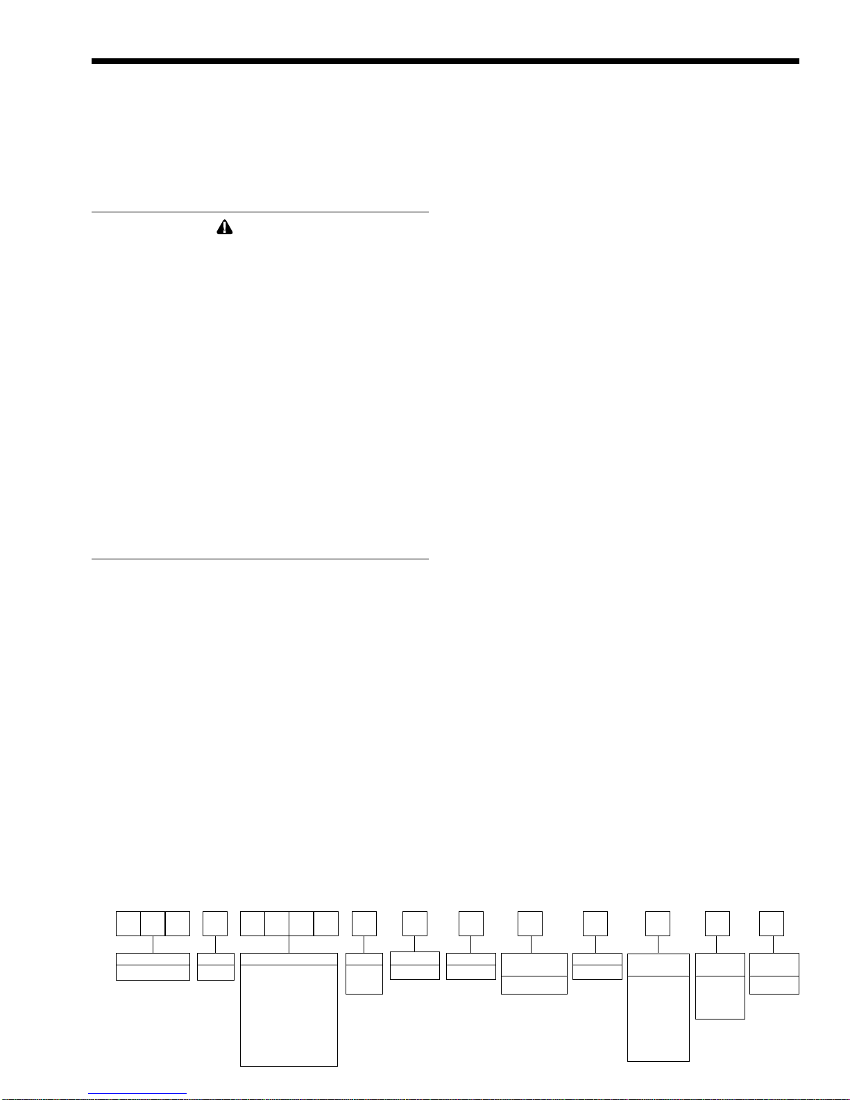
1.2 Model Identification
Consult the rating plate on the unit. The
following information describes the model number
structure.
Model Character Designation
1-3 Model Series Designation
P N C = Pennant
4 Usage
P = Pool Heater
5-8 Size
0 5 0 0 = 500,000 BTU/h input
0 7 5 0 = 750,000 BTU/h input
1 0 0 0 = 999,000 BTU/h input
1 2 5 0 = 1,250,000 BTU/h input
1 5 0 0 = 1,500,000 BTU/h input
1 7 5 0 = 1,750,000 BTU/h input
2 0 0 0 = 1,999,000 BTU/h input
9 Fuel
N = Natural Gas
P = Liquid Propane
10 Altitude
A = 0-10,000 feet
11 Location
C = Indoor and Outdoor
12 Firing Mode
C = On-off
1234567891011 12 13 14 1516
PNC P A C C 2 N
SERIES
PN C
USAGE
P
SIZE
0500
0750
1000
1250
1500
1750
2000
FUEL
N
P
ALTITUDE
A
LOCATION
C
FIRING
MODE
C (ON/OFF)
REVISION
2
HEAT
EXCHANGER
B
C
K
N
P
S
OPTIONS
CODE
X
J
L
PUMP
OPTIONS
N
Page 4
LAARS Heating Systems
13 Revision
2 = Second version
14 Heat Exchanger
B = Glass-lined CI / copper / brz trim (std. PNCP)
K = Bronze / copper
P = Glass-lined cast iron / cu-nickel / brz trim
S = Bronze / cu-nickel
15 Option Code
X = Standard unit
J = CSD-1, FM, IRI, IL
L = MN and LDS (Indoor units only)
16 Pump Options
N = Pump mounted, normal pump
1.3 Warranty
Laars Heating Systems’ Pennant appliances are
covered by a limited warranty. The owner should fill
out the warranty registration card and return it to Laars
Heating Systems.
All warranty claims must be made to an
authorized Laars Heating Systems representative or
directly to the factory. Claims must include the serial
number and model (this information can be found on
the rating plate), installation date, and name of the
installer. Shipping costs are not included in the
warranty coverage.
Some accessory items are shipped in separate
packages. Verify receipt of all packages listed on the
packing slip. Inspect everything for damage
immediately upon delivery, and advise the carrier of
any shortages or damage. Any such claims should be
filed with the carrier. The carrier, not the shipper, is
responsible for shortages and damage to the shipment
whether visible or concealed.
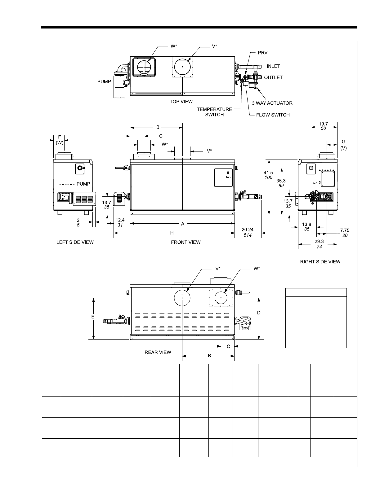
1.4 Dimensions
(See Figure 1.)
1.5 Locating the Appliance
The appliance should be located to provide
clearances on all sides for maintenance and inspection.
It should not be located in an area where leakage of
any connections will result in damage to the area
adjacent to the appliance or to lower floors of the
structure.
When such a location is not available, it is
recommended that a suitable drain pan, adequately
drained, be installed under the appliance.
The appliance is design certified by CSAInternational for installation on combustible flooring;
in basements; in closets, utility rooms or alcoves. The
location for the appliance should be chosen with
regard to the vent pipe lengths and external plumbing.
The unit shall be installed such that the gas ignition
system components are protected from water
(dripping, spraying, rain, etc.) during operation and
service (circulator replacement, control replacement,
etc.). When vented vertically, the Pennant must be
located as close as practical to a chimney or outside
wall. If the vent terminal and/or combustion air
terminal terminate through a wall, and there is
potential for snow accumulation in the local area, both
terminals should be installed at an appropriate level
above grade.
The dimensions and requirements that are shown
in Table 2 should be met when choosing the locations
for the appliance.
HEATER VENT COLLAR VENT PIPE & PIPE MAX. PIPE MAX. NO. SIDE WALL SIDE WALL
HORIZONTAL AIR COLLAR
SIZE SIZE DIAMETER* DIAMETER LENGTH OF ELBOWS VENT COMBUSTION
IN. CM IN. CM IN CM FT. M PART NUMBER PART NUMBER
500 8 20 6 15 6 15 50 15 3 CA001401 20260701
750 10 25 8 20 6 15 50 15 3 CA001402 20260701
1000 10 25 8 20 8 20 50 15 3 CA001402 20260703
1250 12 30 8 20 8 20 50 15 3 CA001403 20260703
1500 12 30 8 20 8 20 50 15 3 CA001403 20260703
1750 14 36 8 20 8 20 50 15 3 CA001405 20260703
2000 14 36 12 30 12 30 50 15 3 CA001404 20260706
*Horizontal venting requires stainless vent pipe. See Table 5.
Table 1. Horizontal Vent / Combustion Air Parameters.
TERMINAL AIR TERMINAL
Pennant Pool Heater
Page 5
Shipping Weight
Size lbs. kg
500 480 218
750 560 254
1000 670 304
1250 730 331
1500 815 370
Dimensions shown in
inches cm
SIZE A B C D E F G H W* V* PIPE
1750 880 400
AIR VENT HORIZ.
CONN. CONN. VENT
500 33½ 85 15¾ 40 5¾ 15 29¾ 76 32¾ 83 7¾ 20 8¾ 22 46 117 6 15 8 20 6 15
750 45½ 116 21¾ 55 5¾ 15 29¾ 76 32¾ 83 7¾ 20 8¾ 22 58 147 6 15 10 25 8 20
1000 57½ 146 28¾ 73 5¾ 15 29¾ 76 32¾ 83 7¾ 20 7 18 70 178 8 20 10 25 8 20
1250 68 172 34 86 101/8 26 30¾ 78 29½ 75 8¾ 22 8¾ 22 80 203 8 20 12 30 8 20
1500 78½ 199 39¾ 101 101/8 26 30¾ 78 29½ 75 8¾ 22 8¾ 22 91 231 8 20 12 30 8 20
1750 89 226 44½ 113 101/8 26 30¾ 78 29½ 75 8¾ 22 8¾ 22 101 256 8 20 14 36 8 20
2000 99½ 253 49¾ 126 101/8 26 30¾ 78 29½ 75 8¾ 22 8¾ 22 112 284 12 30 14 36 12 30
*Air and vent connections may be on top or back of the Pennant, and are field convertible. Dimensions in inches cm.
Figure 1. Dimensional Data.
Page 6
LAARS Heating Systems
1.6 Locating Heater with Respect to Pool
System Loop
For the best results, the Pennant should be
located within 15 feet (4.6m) of the pool system loop.
The pump is sized for 30 feet (9.1m) of piping.
If the appliance must be installed with longer
piping runs, then larger diameter piping shall be used.
Consult the factory for assistance.
1.7 Locating Appliance for Correct
Horizontal Vent/Ducted Air Distance
From Outside Wall
The forced draft combustion air blower/blowers
in the appliance has/have sufficient power to pull air
and vent properly when the following guidelines for
horizontal air and vent are followed (see Table 1).
NOTE: On all model sizes, the vent collar size is larger
than the size of the vent pipe that can be used. Vent
collar size and horizontal pipe diameters can be found
in Table 1. The larger vent collar size is to
accommodate Category I (vertical) vent systems.
NOTE: When located on the same wall, the Pennant
combustion air intake terminal must be installed a
minimum of 12" (30cm) below the exhaust vent
terminal and separated by a minimum of 36 inches
(91cm) horizontally.
The air intake terminal must be installed high
enough to avoid blockage from snow, leaves and other
debris. Never obtain combustion air from the pool
area. Corrosion of and/or damage to the pool heater
may result.
SECTION 2.
Venting and Combustion Air
2.1 Combustion Air
Pennant pool heaters must have provisions for
combustion and ventilation air in accordance with
section 5.3, Air for Combustion and Ventilation, of the
National Fuel Gas Code, ANSI Z223.1, or Sections
7.2, 7.3 or 7.4 of CAN/CGA B149, Installation Codes,
or applicable provisions of the local building codes.
A Pennant appliance may receive combustion air
from the space in which it is installed, or it can be
ducted directly to the unit from the outside.
Ventilation air must be provided in either case. Never
obtain combustion air from the pool area. Corrosion of
and/or damage to the pool heater may result.
2.1.1 Combustion Air From Room
In the United States, the most common
requirements specify that the space shall communicate
with the outdoors in accordance with method 1 or 2,
which follow. Where ducts are used, they shall be of
the same cross-sectional area as the free area of the
openings to which they connect.
Method 1: Two permanent openings, one
commencing within 12 inches (30 cm) of the top and
one commencing within 12 inches (30 cm) of the
bottom, of the enclosure shall be provided. The
openings shall communicate directly, or by ducts, with
the outdoors or spaces that freely communicate with
the outdoors. When directly communicating with the
outdoors, or when communicating to the outdoors
through vertical ducts, each opening shall have a
minimum free area of 1 square inch per 4000 Btu/hr
APPLIANCE CLEARANCE FROM SERVICE ACCESS
REQUIRED RECOMMENDED
SURFACE COMBUSTIBLE MATERIAL CLEARANCE
inches cm inches cm
Left Side 1 2.5 24 61
Right Side 1 2.5 24 61
Top 1 2.5 12 30
Back 1 2.5 **12** 30**
Front 1 2.5 36 91
Vertical
(Category 1) 6* 15.2*
Vent
Horizontal per UL1738 venting
(Category 3) system supplier’s
Vent instructions
*1" (2.5cm) when b-vent is used.
**When vent and/or combustion air connects to the back,
recommended clearance is 36" (91cm).
Table 2. Clearances.
BOILER
SIZE SQUARE INCHES SQUARE CM
500 125 807
750 188 1213
1000 250 1613
1250 313 2020
1500 375 2420
1750 438 2826
2000 500 3226
*Net Free Area in Square Inches / Square cm
Area indicated is for one of two openings; one at floor level and
one at the ceiling, so the total net free area could be double the
figures indicated.
This chart is for use when communicating directly with the
outdoors. For special conditions and alternate methods, refer to
the latest edition of ANSI Z223.1.
Note: Check with louver manufacturers for net free area of
louvers. Correct for screen resistance to the net free area if a
screen is installed. Check all local codes applicable to
combustion air.
Table 3. Combustion Air Openings.
EACH OPENING*
Pennant Pool Heater
Page 7
(5.5 square cm/kW) of total input rating of all
equipment in the enclosure. When communicating to
the outdoors through horizontal ducts, each opening
shall have a minimum free area of not less than
1 square inch per 2000 Btu/hr (11 square cm/kW) of
total input rating of all equipment in the enclosure.
Table 3 shows data for this sizing method, for each
Pennant model.
Method 2: One permanent opening, commencing
within 12 inches (30 cm) of the top of the enclosure,
shall be permitted. The opening shall directly
communicate with the outdoors or shall communicate
through a vertical or horizontal duct to the outdoors or
spaces that directly communicate with the outdoors
and shall have a minimum free area of 1 square inch
per 3000 Btu/hr (7 square cm/kW) of the total input
rating of all equipment located in the enclosure. This
opening must not be less than the sum of the areas of
all vent connectors in the confined space.
Other methods of introducing combustion and
ventilation air are acceptable, providing they conform
to the requirements in the applicable codes listed
above.
In Canada, consult local building and safety
codes or, in absence of such requirements, follow
CAN/CGA B149.
2.1.2 Intake Combustion Air
Never obtain combustion air from the pool area.
Corrosion of and/or damage to the pool heater may
result. The combustion air can be taken through the
wall, or through the roof. When taken from the wall, it
must be taken from out-of-doors by means of the
Laars horizontal wall terminal (see Table 2). When
taken from the roof, a field-supplied rain cap or an
elbow arrangement must be used to prevent entry of
rain water (see Figure 2).
Use single-wall galvanized pipe, per table 4,
for the combustion air intake (see Table 1 for
appropriate size). Route the intake to the heater as
directly as possible. Seal all joints with tape. Provide
adequate hangers. The unit must not support the
weight of the combustion air intake pipe. Maximum
linear pipe length allowed is 50 feet (15.2m). Three
elbows have been calculated into the 50-foot (15.2m)
linear run. Subtract 10 allowable linear feet (3.0m) for
every additional elbow used (see Table 1). When
fewer than 3 elbows are used, the maximum linear
pipe length allowed is still 50 feet (15.2m).
The connection for the intake air pipe is on the
filter box. The Pennant appliances may have venting
and combustion air ducting attached to the top or the
back. They are shipped with the connections at the
top. For attaching either or both pipes to the back, the
mounting flanges are reversible by removing the
mounting screws and orienting the flanges in the
desired position. Replace the screws after positioning
flanges. Run a bead of silicone around the collar and
slide the pipe over the collar. Secure with sheet metal
screws.
In addition to air needed for combustion, air shall
also be supplied for ventilation, including all air
required for comfort and proper working conditions
for personnel. The Pennant loses less than 1 percent of
its input rating to the room, but other heat sources may
be present.
2.2 Venting
2.2.1 Vent Categories
Depending upon desired Pennant venting, it may
be considered a Category I or a Category III
appliance. In general, a vertical vent system will be a
Category I system. However, in rare instances, a
Pennant’s vertical vent system may be considered
Category III. In the U.S., the National Fuel Gas Code
(American National Standard Z223.1-Latest Edition),
or in Canada the CSA B149.1 (latest edition), defines
a Category I vent system, and includes rules and tables
to size these vent systems. If the Pennant’s vertical
vent system does not satisfy the criteria for Category I
venting, it must be vented as a Category III system.
All Pennant vent systems which discharge
horizontally (without the use of a power venter) are
considered Category III vent systems.
TERM DESCRIPTION
Pipe
Joint
Sealing
Table 4. Required Combustion Air Piping Material.
Single-wall galvanized steel pipe, 24 gauge
minimum (either insulated or non-insulated)
Permanent duct tape or aluminum tape
Figure 2. Combustion Air and Vent Through Roof.
Page 8
LAARS Heating Systems
2.2.2 Category I Vent
When vented as a category I appliance, the vent
system must conform to the National Fuel Gas Code
(American National Standard Z223.1-Latest Edition)
in the U.S., or in Canada, to CSA B149.1 (latest
edition). The vent system must be sized and installed
for a Category I Fan-Assisted Appliance.
If chimney height is greater than 25 feet, or if
multiple units are vented into the same vertical vent, a
barometric damper must be installed on each
appliance, such that the flue draft does not exceed
(negative) 0.1" w.c.
If using a power venter for any type of Category
I venting, the draft should be set between (negative)
0.01 and 0.10" w.c.
2.2.3 Common Venting Systems
Pennant units are Category I fan-assisted when
vented vertically and adhering to all applicable codes.
Pennant units are not allowed to be vented into a
common horizontal vent system, unless a properlysized vent fan is used, and the common vent system is
properly designed by the vent fan manufacturer or a
qualified engineer.When common venting Pennant
fan-assisted heaters with other appliances through one
shared vertical duct called a “common vent”, special
care must be taken by the installer to ensure safe
operation. In the event that the common vent is
blocked, it is possible, especially for fan-assisted
devices, to vent backwards through non-operating
appliances sharing the vent, allowing combustion
products to infiltrate occupied spaces. If the
appliances are allowed to operate in this condition,
serious injury or death may occur.
WARNING
Operation of appliances with a blocked common
vent may lead to serious injury or death. Safety
devices must be implemented to prevent blocked
common vent operation. If safe operation of all
appliances connected to a common vent cannot be
assured, including prevention of spillage of flue
gasses into living spaces, common venting should
not be applied, and appliances should each be
vented separately.
It is for this reason that, in addition to following
proper vent sizing, construction and safety
requirements from the National Fuel Gas Code, ANSI
Z223.1 or in Canada, from CSA B149.1 as well as all
applicable local codes, it is required that installers
provide some means to prevent operation with a
blocked common vent. It is suggested that a blocked
vent safety system be employed such that if the switch
from one appliance trips due to excessive stack spill or
backpressure indicating a blocked vent condition, that
all appliances attached to the vent be locked out and
prevented from operating. (Note that the Pennant Pool
Heater is equipped with a blocked vent safety
(pressure) switch, as shipped.) As an additional
precaution, it is recommended that a Carbon
Monoxide (CO) alarm be installed in all enclosed
spaces containing combustion appliances. If assistance
is required in determining how a blocked vent safety
system should be connected to a LAARS product,
please call Applications Engineering at (603) 335-
6300.
Refer to the installation and operating
instructions on all appliances to be common vented for
instructions, warnings, restrictions and safety
requirements. If safe operation of all appliances
connected to a common vent cannot be assured,
including prevention of spillage of flue gasses into
living spaces, common venting should not be applied,
and appliances should each be vented separately.
2.2.4 Category III Vent
When the Pennant is vented with horizontal
discharge, it must be installed per this installation
manual and the venting system manufacturer’s
installation instructions. The vent system must be
sealed stainless steel, per Table 5.
Route the vent pipe to the heater as directly as
possible. Seal all joints and provide adequate hangers
as required in the venting system manufacturer’s
Installation Instructions. Horizontal portions of the
venting system must be supported to prevent sagging
and may not have any low sections that could trap
condensate. The unit must not support the weight of
the vent pipe. Horizontal runs must slope downwards
not less than ¼ inch per foot (2 cm/m) from the unit to
the vent terminal. Reference Table 2 for the size of the
Category III vent system. Up to three elbows can be
used with 50 linear feet (15.2m) of pipe. Subtract 10
allowable linear feet (3.0m) for every additional elbow
used.
TERM DESCRIPTION
Pipe Must comply with UL Standard 1738
such as Type 29-4C Stainless Steel
(either insulated or non-insulated).
Joint Follow vent manufacturer’s instructions
Sealing
Table 5. Required Horizontal Venting Material.
2.3 Locating Vent & Combustion Air
Terminals
2.3.1 Side Wall Vent Terminal
The Laars side wall vent hood (listed in Table 1)
must be used when the heater is vented through a side
wall. It provides a means of installing vent piping
through the building wall, and must be located in
accordance with ANSI Z223.1/NFPA 54 and
applicable local codes. In Canada the installation must
be in accordance with CAN/CGA B149.1 or .2 and
Pennant Pool Heater
Page 9
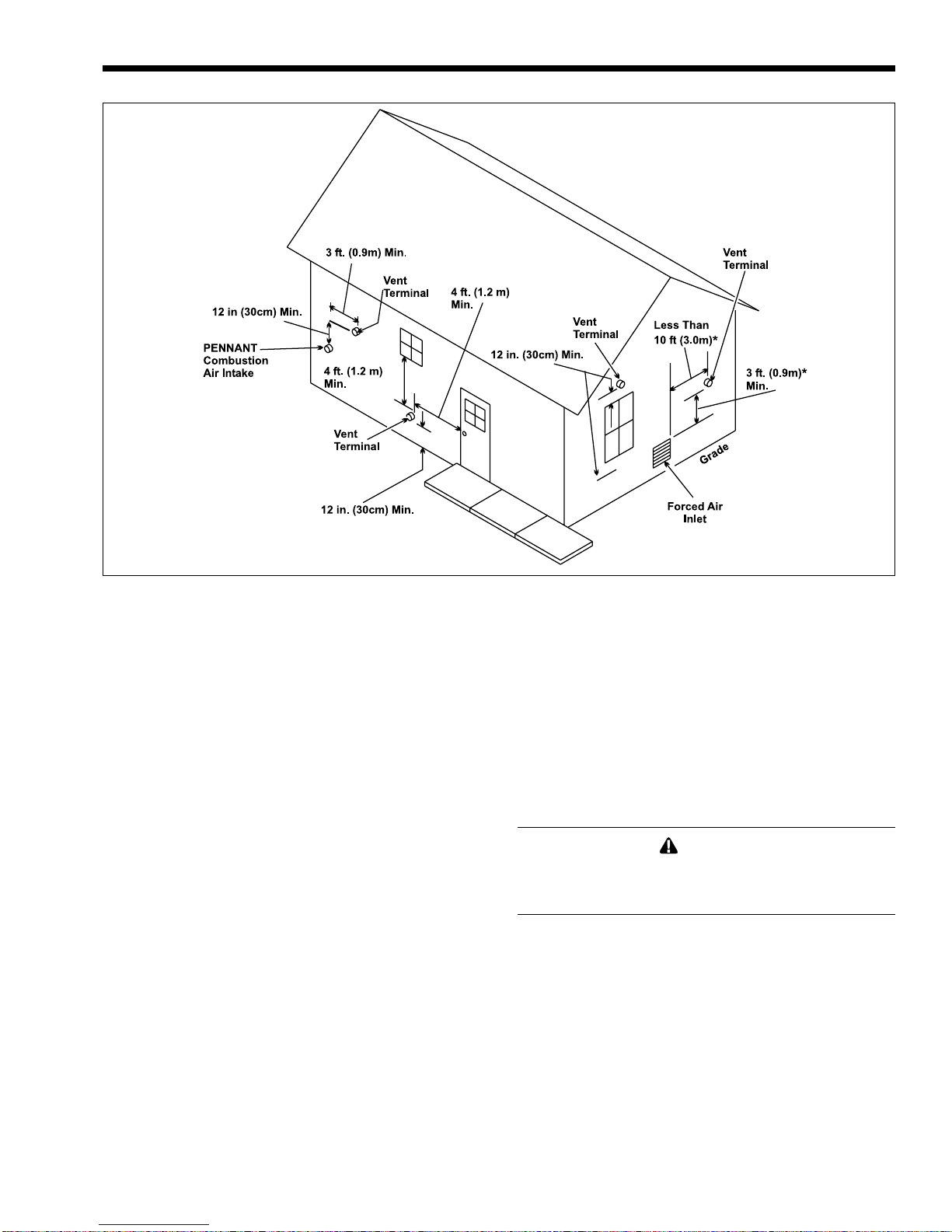
*When vent terminal is less than 10 feet (3m) horizontally
from a forced air inlet, the terminal must be at least 3 feet
(0.9m) above the air inlet.
Figure 3. Combustion Air and Vent Through Side Wall.
local applicable codes (see Figure 3). Consider the
following when installing the terminal:
1. Through-the-wall vent terminals must terminate
at least 7-feet above a public walkway.
2. Locate the vent terminal so that vent gases
cannot be drawn into air conditioning system
inlets. The National Fuel Gas Code requires that
it be at least 3 feet (0.9m) above any such inlet
that is within a horizontal distance of 10 feet (3m).
3. Locate the vent terminal so that vent gases
cannot enter the building through doors,
windows, gravity inlets or other openings. The
National Fuel Gas Code requires that it be
located at least 4 feet (1.2m) below, 4 feet (1.2m)
horizontally from, or 1 foot (0.3m) above such
openings. Whenever possible, locations under
windows or near doors should be avoided.
4. Locate the vent terminal so that it cannot be
blocked by snow. The National Fuel Gas Code
requires that it be at least 12 inches (30 cm)
above grade, but the installer may determine it
should be higher, depending upon local
conditions.
5. Locate the terminal so the vent exhaust does not
settle on building surfaces and other nearby
objects. Vent products may damage such
surfaces or objects.
6. Locate the terminal at least 6 feet (1.8m)
horizontally from any gas or electric metering,
regulating, or relief equipment.
7. If the Pennant uses ducted combustion air from
an intake terminal located on the same wall,
locate the vent terminal at least 3 feet (0.9m)
horizontally from the combustion air terminal,
and locate the vent terminal at least 1 foot (0.3m)
above the combustion air terminal.
8. Note that side wall vent terminals for models
750-2000 are shipped with reducers for the vent
collars, to accommodate horizontal vent sizes,
shown in Table 1.
WARNING
The outdoor vent terminal gets hot. Unit must be
installed in such a way as to reduce the risk of
burns from contact with the vent terminal.
2.3.2 Side Wall Combustion Air Terminal
Never obtain combustion air from the pool area.
Corrosion of and/or damage to the pool heater may
result. The Laars side wall combustion air terminal
(listed in Table 1) must be used when the unit takes its
combustion air through a duct from a side wall.
Consider the following when installing the terminal:
1. Do not locate the air inlet terminal near a source
of corrosive chemical fumes (e.g., cleaning fluid,
chlorinated compounds, etc.)
2. Locate the terminal so that it will not be subject
to damage by accident or vandalism.
3. Locate the combustion air terminal so that it
cannot be blocked by snow. The National Fuel

Page 10
LAARS Heating Systems
Gas Code requires that it be at least 12 inches
(30 cm) above grade, but the installer may
determine it should be higher, depending upon
local conditions.
4. If the Pennant is side-wall vented to the same
wall, locate the vent terminal at least 3 feet
(0.9m) horizontally from the combustion air
terminal, and locate the vent terminal at least 1
foot (0.3m) above the combustion air terminal
(see Figure 3).
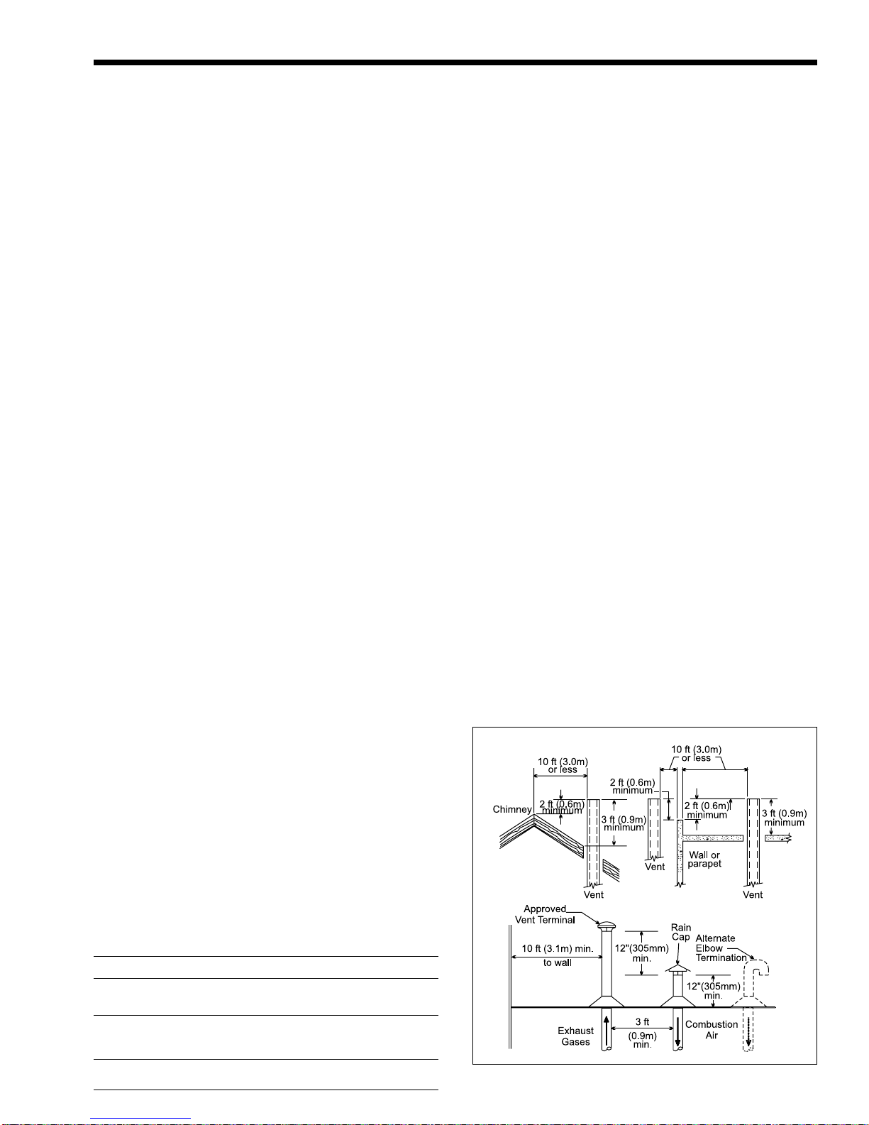
2.3.3 Vertical Vent Terminal
When the unit is vented through the roof, the
vent must extend at least 3 feet (0.9m) above the point
at which it penetrates the roof. It must extend at least 2
feet (0.6m) higher than any portion of a building
within a horizontal distance of 10 feet (3.0m), and
high enough above the roof line to prevent blockage
from snow. When the combustion air is taken from the
roof, the combustion air must terminate at least 12"
(30cm) below the vent terminal (see Figure 2).
2.3.4 Vertical Combustion Air Terminal
When combustion air is taken from the roof, a
field-supplied rain cap or an elbow arrangement must
be used to prevent entry of rain water (see Figure 2).
The opening on the end of the terminal must be at
least 12" (30cm) above the point at which it penetrates
the roof, and high enough above the roof line to
prevent blockage from snow. When the vent
terminates on the roof, the combustion air must
terminate at least 12" (30cm) below the vent terminal.
2.4 Vent Terminals for Outdoor Units
For outdoor applications, the vent and
combustion air openings must be covered with proper
terminals to prevent rain, snow and other objects from
falling into the Pennant.
Part numbers for the terminals to cover the vent
and combustion air openings are shown in Table 6.
Vent opening must be on top of the unit, and the
combustion air opening must be on the back of the
unit. The terminals are connected directly to the unit.
No vent piping is used.
Alternately, the installer may use a short piece of
OUTDOOR VENT OUTDOOR
SIZE TERMINAL COMBUSTION
AIR TERMINAL
500 20254703 D2007900
750 20254705 D2007900
1000 20254705 D2008000
1250 D2007700 D2008000
1500 D2007700 D2008000
1750 D2007800 D2008000
2000 D2007800 D2008200
galvanized single wall or B-vent and an approved rain
cap for the vent termination. A minimum 12" of vent
height is acceptable. In addition, a properly sized
single wall galvanized 90° ell can be used for the
intake air terminal, with the open end of the ell facing
down to prevent rain infiltration. The combustion air
inlet opening must still be high enough to prevent
blockage by snow (see Section 2.3.2).
SECTION 3.
Gas Supply and Piping
3.1 Gas Supply and Piping
Gas piping should be supported by suitable
hangers or floor stands, not by the appliance.
The Pennant’s gas train allows the user to pipe
the gas from either the right side or the left side of the
unit. As shipped, the right side of the gas train is
capped off, and there is a manual valve on the left
side. If desired, the manual valve on the left side of the
gas train may be moved to the right side, and the cap
on the right side may be moved to the left.
Review the following instructions before
proceeding with the installation.
1. Verify that the appliance is fitted for the proper
type of gas by checking the rating plate. Laars
Heating Systems appliances are normally
equipped to operate at elevations up to 2000
feet (610m). Pennant appliances may be adjusted
to operate properly at higher elevations;
however, input will be reduced if the heating
value of the gas supply is below sea level values.
2. The maximum inlet gas pressure must not exceed
DISTANCE FROM GAS METER
SIZE AND
GAS TYPE 0-100' 0-31m 100-200' 31-61m 200-300' 61-91m
500 natural 1-1/2" 3.8cm 2" 5.1cm 2" 5.1cm
500 propane 1" 2.5cm 1-1/2" 3.8cm 1-1/2" 3.8cm
750 natural 2" 5.1cm 2" 5.1cm 2-1/2" 6.4cm
750 propane 1-1/2" 3.8cm 1-1/2" 3.8cm 2" 5.1cm
1000 natural 2" 5.1cm 2-1/2" 6.4cm 3" 7.6cm
1000 propane 1-1/2" 3.8cm 2" 5.1cm 2-1/2" 6.4cm
1250 natural 2-1/2" 6.4cm 2-1/2" 6.4cm 3" 7.6cm
1250 propane 2" 5.1cm 2" 5.1cm 2-1/2" 6.4cm
1500 natural 2-1/2" 6.4cm 3" 7.6cm 3" 7.6cm
1500 propane 2" 5.1cm 2-1/2" 6.4cm 2-1/2" 6.4cm
1750 natural 2-1/2" 6.4cm 3" 7.6cm 3" 7.6cm
1750 propane 2" 5.1cm 2-1/2" 6.4cm 2-1/2" 6.4cm
2000 natural 3" 7.6cm 3" 7.6cm 3-1/2" 8.9cm
2000 propane 2-1/2" 6.4cm 2-1/2" 6.4cm 3" 7.6cm
Notes:
1. These figures are based on 1/2" (0.12kPa) water column
pressure drop.
2. Check supply pressure and local code requirements before
proceeding with work.
3. Pipe fittings must be considered when determining gas pipe
sizing.
OR LAST STAGE REGULATOR
Table 6. Vent Terminals for Outdoor Units
Table 7. Gas Piping Size.
Pennant Pool Heater
Page 11
13" W.C (3.2kPa). The minimum inlet gas
pressure is 5" W.C. (1.2kPa).
3. Refer to Table 7, size supply.
4. Run gas supply line in accordance with all
applicable codes.
5. Locate and install manual shutoff valves in
accordance with state and local requirements.
6. A sediment trap must be provided upstream of
the gas controls.
7. All threaded joints should be coated with piping
compound resistant to action of liquefied
petroleum gas.
8. The appliance and its individual shutoff valve
must be disconnected from the gas supply piping
during any pressure testing of that system at test
pressures in excess of 1/2 PSIG (3.45kpa).
9. The unit must be isolated from the gas supply
system by closing its individual manual shutoff
valve during any pressure testing of the gas
supply piping system at test pressures equal to or
less than 1/2 PSIG (3.45kpa).
10. The appliance and its gas connection must be
leak tested before placing it in operation.
11. Purge all air from gas lines.
Caution
Do not use open flame to check for leaks.
NOTE: The Pennant appliance and all other gas
appliances sharing the gas supply line must be firing
at maximum capacity to properly measure the inlet
supply pressure. The pressure can be measured at
the supply pressure port on the gas valve. Low gas
pressure could be an indication of an undersized gas
meter, undersized gas supply lines and/or an
obstructed gas supply line. The Pennant may not fire if
the gas pressure lower than 5" w.c.
SECTION 4.
Water Connections
4.1 Piping
Hot water piping should be supported by suitable
hangers or floor stands. Do not support piping with
this appliance. Due to expansion and contraction of
copper pipe, consideration should be given to the type
of hangers used. Rigid hangers may transmit noise
through the system resulting from the piping sliding in
the hangers. It is recommended that padding be used
when rigid hangers are installed. Maintain 1"
clearance to combustibles for hot water pipes.
Pipe the discharge of the relief valve (full size) to
a drain or in a manner to prevent injury in the event of
pressure relief. Install shutoff valves where required
by code.
Pennant Pool Heaters are equipped with mounted
pumps, which serve the heater plus 30 feet of fullsized piping with a normal number of fittings. If the
pool’s loop is more than 15 feet away from the heater,
please contact the factory.
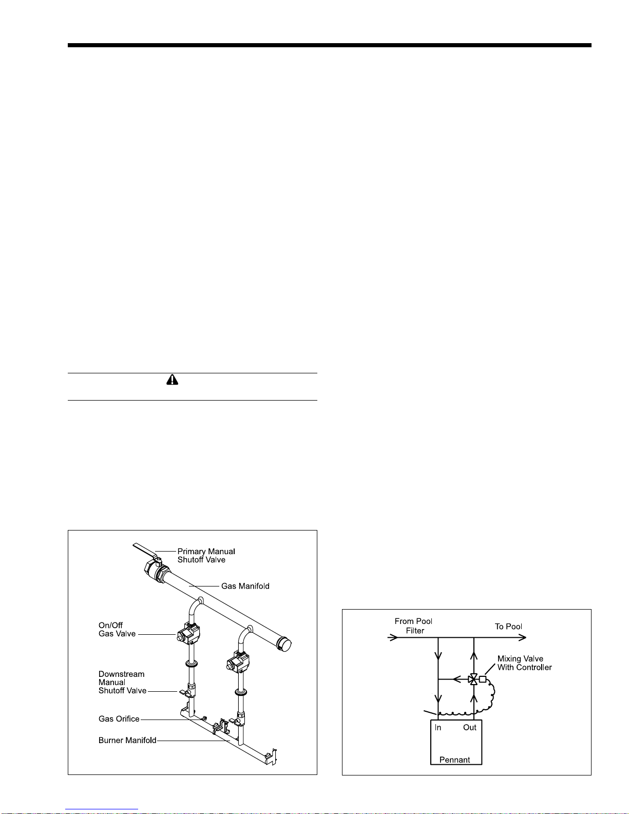
A mixing system is mounted on the heater. The
system consists of a three-way valve, temperature
control and piping. The temperature sensor for the
control is in the heater inlet. When the control detects
water temperature that is below 120°F (49°C), it will
direct the three-way valve to actuate, which sends
water from the outlet of the heater back to the inlet.
The outlet water that is diverted to the inlet mixes with
the return water from the pool, and keeps the inlet
temperature at or above 120°F (49°C) (see Figure 5).
This keeps cold return water from causing condensing
on the outside of the Pennant heat exchanger.
IMPORTANT NOTE: Since heater outlet
temperatures can reach 150°F (66°C) in some cases,
copper or CPVC are recommended materials for
heater connection piping. PVC material may be used
for the inlet valve and the piping upstream of it.
When pipe, fittings, grids or any other element of
the filter system are made of plastic materials, they
may be damaged by the momentary “back siphoning”
Mixing Controller
Sensor (120°F)
Pool Loop / Inlet
(2 used)
Figure 5. Mixing System.Figure 4. Typical Gas Train Configuration.
 Loading...