

Page 1
Installation and Operation Instructions Document 3164E
Installation and Operation
Instructions for
™
PENNANT
Pool Heater
Model PNCP
U.S. Reg. 2,765,423
FOR YOUR SAFETY: This product must be installed and serviced by a professional service technician,
qualied in hot water boiler installation and maintenance. Improper installation and/or operation could
create carbon monoxide gas in ue gases which could cause serious injury, property damage, or death.
Improper installation and/or operation will void the warranty.
WARNING
If the information in this manual is not
followed exactly, a re or explosion may
result causing property damage, personal
injury or loss of life.
Do not store or use gasoline or other
ammable vapors and liquids in the vicinity
of this or any other appliance.
WHAT TO DO IF YOU SMELL GAS
• Do not try to light any appliance.
• Do not touch any electrical switch; do not
use any phone in your building.
• Immediately call your gas supplier from a
nearby phone. Follow the gas supplier's
instructions.
• If you cannot reach your gas supplier, call
the re department.
Installation and service must be performed
by a qualied installer, service agency, or gas
supplier.
Assurez-vous de bien suivres les instructions
données dans cette notice pour réduire au
minimum le risque d’incendie ou d’explosion
ou pour éviter tout dommage matériel, toute
blessure ou la mort.
Ne pas entreposer ni utiliser d’essence ni
d’autres vapeurs ou liquides inammables dans
le voisinage de cet appareil ou de tout autre
appareil.
QUE FAIRE SI VOUS SENTEZ UNE ODEUR DE GAZ:
• Ne pas tenter d’allumer d’appareils.
• Ne touchez à aucun interrupteur. Ne pas vous
servir des téléphones dansle bâtiment où vous
vous trouvez.
• Appelez immédiatement votre fournisseur de
gaz depuis un voisin. Suivez les instructions
du fournisseur.
• Si vous ne pouvez rejoindre le fournisseur de
gaz, appelez le sservice des incendies.
L’installation et l’entretien doivent être assurés par
un installateur ou un service d’entretien qualié ou
par le fournisseur de gaz.
AVERTISSEMENT
H2311900E
Page 2

Page 2
LAARS Heating Systems
TABLE OF CONTENTS
SECTION 1.
General Information
1.1 Introduction ...................................................... 3
1.2 Model Identication .......................................... 3
1.3 Warranty .......................................................... 4
1.4 Dimensions ...................................................... 4
1.5 Locating the Appliance..................................... 4
1.6 Locating Heater with Respect to Pool
System Loop .................................................... 6
1.7 Locating Appliance for Correct Horizontal Vent/
Ducted Air Distance From Outside Wall .......... 6
SECTION 2.
Venting and Combustion Air
2.1 Combustion Air ................................................ 6
2.1.1 Combustion Air From Room ............................ 6
2.1.2 Intake Combustion Air...................................... 7
2.2 Venting ............................................................. 7
2.2.1 Vent Categories ............................................... 7
2.2.2 Category I Vent ................................................ 8
2.2.3 Common Venting Systems .............................. 8
2.2.4 Category III Vent .............................................. 8
2.3 Locating Vent & Combustion Air Terminals ...... 8
2.3.1 Side Wall Vent Terminal ................................... 8
2.3.2 Side Wall Combustion Air Terminal .................. 9
2.3.3 Vertical Vent Terminal .................................... 10
2.3.4 Vertical Combustion Air Terminal ................... 10
2.4 Vent Terminals for Outdoor Units ................... 10
SECTION 3.
Gas Supply and Piping
3.1 Gas Supply and Piping ...................................11
SECTION 4A.
Water Connections
4.1 Piping ............................................................. 12
4.2 Automatic Chlorinators .................................. 13
4.3 Sensor Locations ........................................... 13
SECTION 5.
Electrical Connections
5.1 Main Power .................................................... 13
5.1.1 Sizes 500-1500 .............................................. 13
5.1.2 Sizes 1750-2000 ............................................ 13
5.1.3 Separate Pump Circuit................................... 13
5.1.4 Auxiliary Time Clock Wiring ........................... 14
5.1.5 All Sizes ......................................................... 14
5.2 Temperature (Operating) Control .................. 14
5.3 Programming the Temperature Control ......... 14
5.3.1 Temperature Control Overview ...................... 14
5.3.2 Programming Control Parameters ................. 14
5.3.3 Setpoint - LSP ................................................ 15
5.3.4 Differential - dLS ............................................ 16
5.3.5 Pump Operation............................................. 16
5.3.6 Heater Purge (Pump Delay) - PD .................. 16
5.4 Limit Controls ................................................. 16
SECTION 6.
Operating Instructions
6.1 Sequence of Operation .................................. 16
6.2 Filling the Heater System............................... 17
6.3 Operating the Burner and Set Up .................. 17
6.3.1 Set Up for 0 to 2500 Feet Altitude.................. 17
6.3.2 High Altitude Adjustment and Set Up ............. 18
6.4 Shutting Down the Pennant ........................... 18
6.5 Backwash Switch Operation .......................... 18
6.6 Spring and Fall Operation
Stand-by Service ........................................... 19
6.7 Winter Operation............................................ 19
6.8 To Restart the Pennant .................................. 19
6.9 Therapeutic Pools (Spas) .............................. 19
SECTION 7.
Maintenance
7.1 System Maintenance ..................................... 20
7.2 Appliance Maintenance and
Component Description ................................. 20
7.2.1 Burners .......................................................... 20
7.2.2 Filter ............................................................... 20
7.2.3 Gas Valves ..................................................... 20
7.2.4 Pool Loop High Limit Control ......................... 20
7.2.5 Automatic Reset High Limit Control ............... 20
7.2.6 Temperature Control ...................................... 21
7.2.7 Ignition Controls ............................................. 21
7.2.8 Ignitors ........................................................... 21
7.2.9 Ignition Sensors ............................................. 21
7.2.10 Transformer ................................................... 21
7.2.11 Blowers .......................................................... 21
7.2.12 Flow Switch ................................................... 21
7.2.13 Heat Exchanger Coil...................................... 21
SECTION 8.
Trouble Shooting
8.1 Resolving Lockouts........................................ 22
8.2 Delayed Ignition – Possible Causes .............. 22
8.3 Short Cycling ................................................. 22
8.4 High Gas Consumption.................................. 23
8.5 Troubleshooting the Pool Heater
Temperature Control ...................................... 23
8.6 Troubleshooting Pennant Controls ................ 23
SECTION 9.
Replacement Parts
9.1 General Information ....................................... 23
9.2 Parts List ........................................................ 23
Page 3
Pennant Pool Heater
Page 3
SECTION 1.
General Information
In the Commonwealth of Massachusetts, this
appliance must be installed by a licensed plumber or
gas tter.
WARNING
The Pennant pool heater must be installed in
accordance with the procedures detailed in this
manual, or the Laars Heating Systems warranty
may be voided. The installation must conform to
the requirements of the local jurisdiction having
authority, and, in the United States, to the latest
edition of the National Fuel Gas Code, ANSI
Z223.1/NFPA54. In Canada, the installation must
conform to the latest edition of CAN/CGA-B149.1,
Natural Gas Installation Code or CAN/CGA-B149.2,
Propane Gas Installation Code, and/or local codes.
Where required by the authority having jurisdiction,
the installation of Pennant appliances must
conform to the Standard for Controls and Safety
Devices for Automatically Fired Boilers, ANSI/
ASME CSD-1. Any modications to the boiler, its
gas controls, or wiring may void the warranty. If eld
conditions require modications, consult the factory
representative before initiating such modications.
1.1 Introduction
This manual provides information necessary for
the installation, operation, and maintenance of Laars
Heating Systems Pennant copper tube pool heaters.
Read it carefully before installation.
All application and installation procedures
should be reviewed completely before proceeding with
the installation. Consult the Laars Heating Systems
factory, or local factory representative, with any issues
or questions regarding this equipment. Experience
has shown that most operating issues are caused by
improper installation.
The Pennant appliance is protected against over
pressurization. A pressure relief valve is tted to all
appliances. It is installed on the outlet header, at the
water outlet of the appliance.
IMPORTANT: The inlet gas pressure to the appliance
must not exceed 13" W.C. (3.2kPa).
All installations must be made in accordance
with the 1). American National Standard Z223.1/
NFPA54-Latest Edition “National Fuel Gas Code”
or 2). CAN/CGA 1-B149 “Installation Codes for Gas
Burning Appliances and Equipment” and with the
requirement of the local utility or other authorities
having jurisdiction. Such applicable requirements take
precedence over the general instructions contained
herein.
All electrical wiring is to be done in accordance
with the local codes, or in the absence of local
codes, with: 1). The National Electrical Code ANSI/
NFPA No. 70-latest Edition, or 2). CSA STD. C22.1
“Canadian Electrical Code - Part 1”. This appliance
must be electrically grounded in accordance with these
codes.
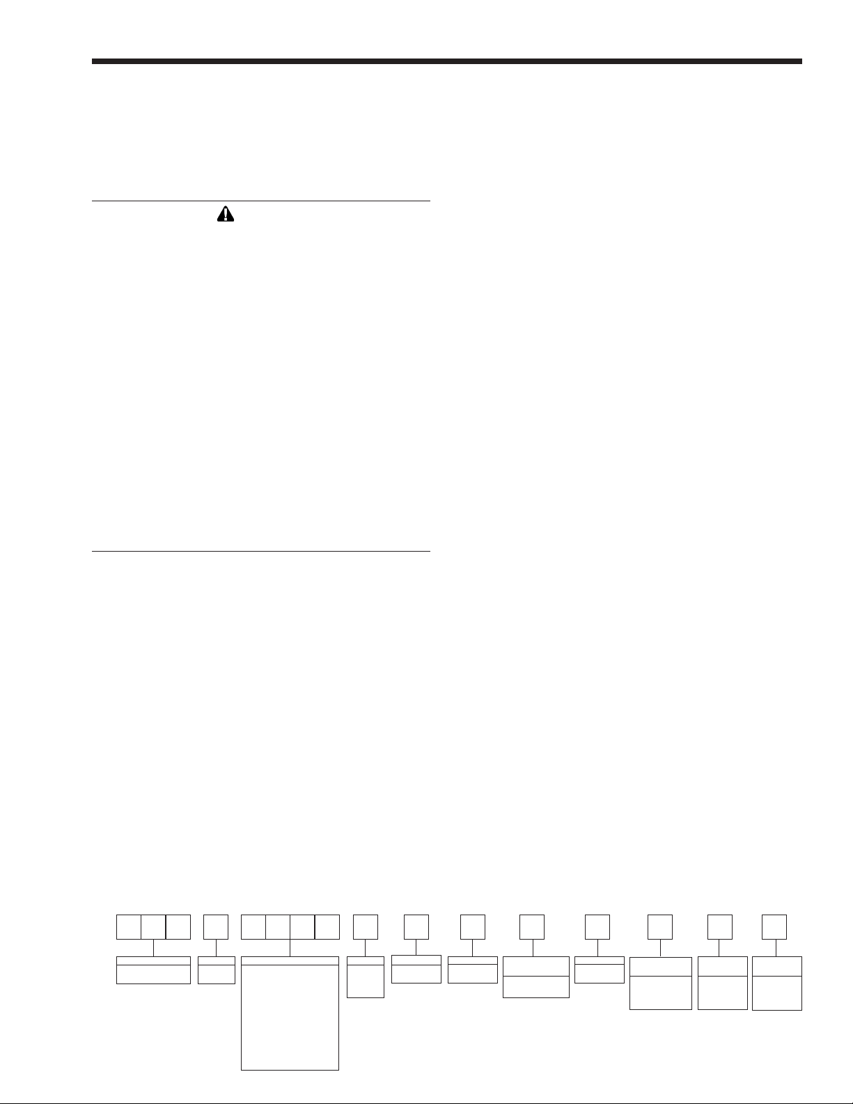
1.2 Model Identication
Consult the rating plate on the unit. The
following information describes the model number
structure.
Model Character Designation
1-3 Model Series Designation
P N C = Pennant
4 Usage
P = Pool Heater
5-8 Size
0 5 0 0 = 500,000 BTU/h input
0 7 5 0 = 750,000 BTU/h input
1 0 0 0 = 999,000 BTU/h input
1 2 5 0 = 1,250,000 BTU/h input
1 5 0 0 = 1,500,000 BTU/h input
1 7 5 0 = 1,750,000 BTU/h input
2 0 0 0 = 1,999,000 BTU/h input
9 Fuel
N = Natural Gas
P = Liquid Propane
10 Altitude
A = 0-10,000 feet
11 Location
C = Indoor and Outdoor
12 Firing Mode
C = On-off
13 Revision
2 = Second version
1 2 3 4 5 6 7 8 9 10 11 12 13 14 15 16
P N C P A C C 2
SERIES
P N C
USAGE
P
SIZE
0 5 0 0
0 7 5 0
1 0 0 0
1 2 5 0
1 5 0 0
1 7 5 0
2 0 0 0
FUEL
N
P
ALTITUDE
A
LOCATION
C
FIRING
MODE
C (ON/OFF)
REVISION
2
HEAT
EXCHANGER
B
P
OPTIONS
CODE
X
J
PUMP
OPTIONS
N
B
Page 4

Page 4
LAARS Heating Systems
14 Heat Exchanger
B = Glass-lined CI / copper / brz trim (std. PNCP)
P = Glass-lined cast iron / cu-nickel / brz trim
15 Option Code
X = Standard unit
J = CSD-1, FM, IRI, IL
16 Pump Options
N = Pump mounted, TACO, normal water pump
B = Pump mounted, B&G, optional normal water pump
1.3 Warranty
Laars Heating Systems appliances are covered
by a limited warranty. Owners should submit online
warranty registration at www.Laars.com.
All warranty claims must be made to an authorized
Laars Heating Systems representative, directly to
Customer Service, or online at www.Laars.com.
Claims must include the serial number and model
(this information can be found on the rating plate),
installation date, and name of the installer. Shipping
costs are not included in the warranty coverage.
Some accessory items are shipped in separate
packages. Verify receipt of all packages listed on
the packing slip. Inspect everything for damage
immediately upon delivery, and advise the carrier of
any shortages or damage. Any such claims should be
led with the carrier. The carrier, not the shipper, is
responsible for shortages and damage to the shipment
whether visible or concealed.
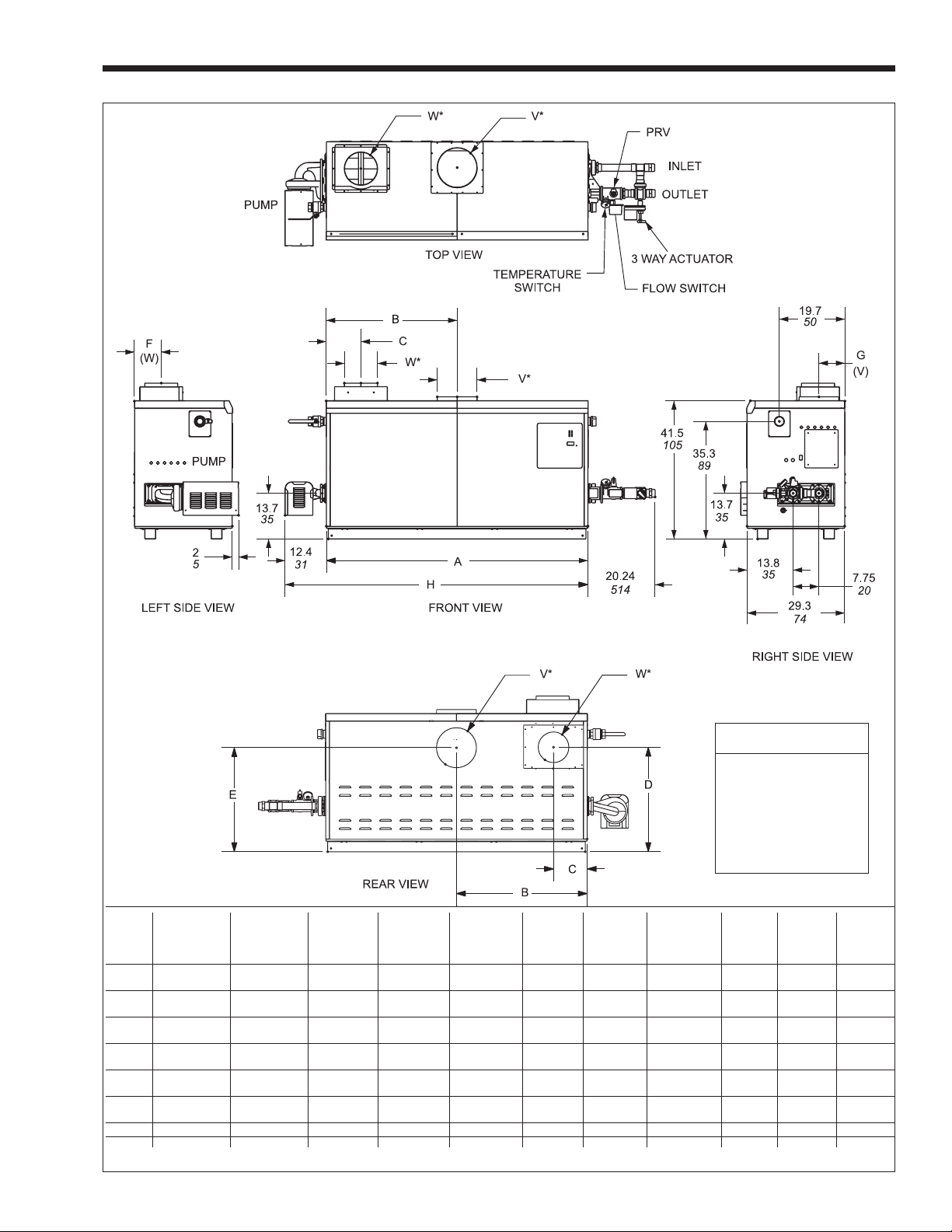
1.4 Dimensions
(See Figure 1.)
1.5 Locating the Appliance
The appliance should be located to provide
clearances on all sides for maintenance and inspection.
It should not be located in an area where leakage of
any connections will result in damage to the area
adjacent to the appliance or to lower oors of the
structure.
When such a location is not available, it is
recommended that a suitable drain pan, adequately
drained, be installed under the appliance.
The appliance is design certied by CSAInternational for installation on combustible ooring;
in basements; in closets, utility rooms or alcoves.
The location for the appliance should be chosen
with regard to the vent pipe lengths and external
plumbing. The unit shall be installed such that the gas
ignition system components are protected from water
(dripping, spraying, rain, etc.) during operation and
service (circulator replacement, control replacement,
etc.). When vented vertically, the Pennant must
be located as close as practical to a chimney or
outside wall. If the vent terminal and/or combustion
air terminal terminate through a wall, and there is
potential for snow accumulation in the local area, both
terminals should be installed at an appropriate level
above grade.
The dimensions and requirements that are shown
in Table 2 should be met when choosing the locations
for the appliance.
HORIZONTAL AIR COLLAR
HEATER VENT COLLAR VENT PIPE & PIPE MAX. PIPE MAX. NO. SIDE WALL SIDE WALL
SIZE SIZE DIAMETER* DIAMETER LENGTH OF ELBOWS VENT COMBUSTION
TERMINAL AIR TERMINAL
IN. CM IN. CM IN CM FT. M PART NUMBER PART NUMBER
500 8 20 6 15 6 15 50 15 3 CA001401 20260701
750 10 25 8 20 6 15 50 15 3 CA001402 20260701
1000 10 25 8 20 8 20 50 15 3 CA001402 20260703
1250 12 30 8 20 8 20 50 15 3 CA001403 20260703
1500 12 30 8 20 8 20 50 15 3 CA001403 20260703
1750 14 36 8 20 8 20 50 15 3 CA001405 20260703
2000 14 36 12 30 12 30 50 15 3 CA001404 20260706
*Horizontal venting requires stainless vent pipe. See Table 5.
Table 1. Horizontal Vent / Combustion Air Parameters.
Page 5
Pennant Pool Heater
Page 5
Shipping Weight
Size lbs. kg
500 480 218
750 560 254
1000 670 304
1250 730 331
1500 815 370
1750 880 400
Dimensions shown in
inches cm
AIR VENT HORIZ.
CONN. CONN. VENT
SIZE A B C D E F G H W* V* PIPE
500 33½ 85 15¾ 40 5¾ 15 29¾ 76 32¾ 83 7¾ 20 8¾ 22 46 117 6 15 8 20 6 15
750 45½ 116 21¾ 55 5¾ 15 29¾ 76 32¾ 83 7¾ 20 8¾ 22 58 147 6 15 10 25 8 20
1000 57½ 146 28¾ 73 5¾ 15 29¾ 76 32¾ 83 7¾ 20 7 18 70 178 8 20 10 25 8 20
1250 68 172 34 86 101/8 26 30¾ 78 29½ 75 8¾ 22 8¾ 22 80 203 8 20 12 30 8 20
1500 78½ 199 39¾ 101 101/8 26 30¾ 78 29½ 75 8¾ 22 8¾ 22 91 231 8 20 12 30 8 20
1750 89 226 44½ 113 101/8 26 30¾ 78 29½ 75 8¾ 22 8¾ 22 101 256 8 20 14 36 8 20
2000 99½ 253 49¾ 126 101/8 26 30¾ 78 29½ 75 8¾ 22 8¾ 22 112 284 12 30 14 36 12 30
*Air and vent connections may be on top or back of the Pennant, and are eld convertible. Dimensions in inches cm.
Figure 1. Dimensional Data.
Page 6

Page 6
LAARS Heating Systems
1.6 Locating Heater with Respect to Pool
System Loop
For the best results, the Pennant should be
located within 15 feet (4.6m) of the pool system loop.
The pump is sized for 30 feet (9.1m) of piping.
If the appliance must be installed with longer
piping runs, then larger diameter piping shall be used.
Consult the factory for assistance.
1.7 Locating Appliance for Correct
Horizontal Vent/Ducted Air Distance
From Outside Wall
The forced draft combustion air blower/blowers
in the appliance has/have sufcient power to pull air
and vent properly when the following guidelines for
horizontal air and vent are followed (see Table 1).
NOTE: On all model sizes, the vent collar size is
larger than the size of the vent pipe that can be used.
Vent collar size and horizontal pipe diameters can
be found in Table 1. The larger vent collar size is to
accommodate Category I (vertical) vent systems.
NOTE: When located on the same wall, the Pennant
combustion air intake terminal must be installed
a minimum of 12" (30cm) below the exhaust vent
terminal and separated by a minimum of 36 inches
(91cm) horizontally.
The air intake terminal must be installed high
enough to avoid blockage from snow, leaves and other
debris. Never obtain combustion air from the pool
area. Corrosion of and/or damage to the pool heater
may result.
SECTION 2.
Venting and Combustion Air
2.1 Combustion Air
Pennant pool heaters must have provisions for
combustion and ventilation air in accordance with
section 5.3, Air for Combustion and Ventilation, of the
National Fuel Gas Code, ANSI Z223.1, or Sections
7.2, 7.3 or 7.4 of CAN/CGA B149, Installation Codes,
or applicable provisions of the local building codes.
A Pennant appliance may receive combustion
air from the space in which it is installed, or it can be
ducted directly to the unit from the outside. Ventilation
air must be provided in either case. Never obtain
combustion air from the pool area. Corrosion of and/or
damage to the pool heater may result.
2.1.1 Combustion Air From Room
In the United States, the most common
requirements specify that the space shall communicate
with the outdoors in accordance with method 1 or 2,
which follow. Where ducts are used, they shall be of
the same cross-sectional area as the free area of the
openings to which they connect.
Method 1: Two permanent openings, one
commencing within 12 inches (30 cm) of the top
and one commencing within 12 inches (30 cm) of
the bottom, of the enclosure shall be provided. The
openings shall communicate directly, or by ducts,
with the outdoors or spaces that freely communicate
with the outdoors. When directly communicating
with the outdoors, or when communicating to the
outdoors through vertical ducts, each opening shall
have a minimum free area of 1 square inch per 4000
REQUIRED RECOMMENDED
APPLIANCE CLEARANCE FROM SERVICE ACCESS
SURFACE COMBUSTIBLE MATERIAL CLEARANCE
inches cm inches cm
Left Side 1 2.5 24 61
Right Side 1 2.5 24 61
Top 1 2.5 12 30
Back 1 2.5 **12** 30**
Front 1 2.5 36 91
Vertical
(Category 1) 6* 15.2*
Vent
Horizontal per UL1738 venting
(Category 3) system supplier’s
Vent instructions
*1" (2.5cm) when b-vent is used.
**When vent and/or combustion air connects to the back,
recommended clearance is 36" (91cm).
Table 2. Clearances.
BOILER EACH OPENING*
SIZE SQUARE INCHES SQUARE CM
500 125 807
750 188 1213
1000 250 1613
1250 313 2020
1500 375 2420
1750 438 2826
2000 500 3226
*Net Free Area in Square Inches / Square cm
Area indicated is for one of two openings; one at oor level and
one at the ceiling, so the total net free area could be double the
gures indicated.
This chart is for use when communicating directly with the
outdoors. For special conditions and alternate methods, refer to
the latest edition of ANSI Z223.1.
Note: Check with louver manufacturers for net free area of
louvers. Correct for screen resistance to the net free area
if a screen is installed. Check all local codes applicable to
combustion air.
Table 3. Combustion Air Openings.
Page 7
Pennant Pool Heater
Page 7
Btu/hr (5.5 square cm/kW) of total input rating of all
equipment in the enclosure. When communicating to
the outdoors through horizontal ducts, each opening
shall have a minimum free area of not less than
1 square inch per 2000 Btu/hr (11 square cm/kW) of
total input rating of all equipment in the enclosure.
Table 3 shows data for this sizing method, for each
Pennant model.
Method 2: One permanent opening, commencing
within 12 inches (30 cm) of the top of the enclosure,
shall be permitted. The opening shall directly
communicate with the outdoors or shall communicate
through a vertical or horizontal duct to the outdoors
or spaces that directly communicate with the outdoors
and shall have a minimum free area of 1 square inch
per 3000 Btu/hr (7 square cm/kW) of the total input
rating of all equipment located in the enclosure. This
opening must not be less than the sum of the areas of
all vent connectors in the conned space.
Other methods of introducing combustion and
ventilation air are acceptable, providing they conform
to the requirements in the applicable codes listed
above.
In Canada, consult local building and safety
codes or, in absence of such requirements, follow
CAN/CGA B149.
2.1.2 Intake Combustion Air
Never obtain combustion air from the pool area.
Corrosion of and/or damage to the pool heater may
result. The combustion air can be taken through the
wall, or through the roof. When taken from the wall, it
must be taken from out-of-doors by means of the Laars
horizontal wall terminal (see Table 1). When taken
from the roof, a eld-supplied rain cap or an elbow
arrangement must be used to prevent entry of rain
water (see Figure 2).
Use single-wall galvanized pipe, per table
4, for the combustion air intake (see Table 1 for
appropriate size). Route the intake to the heater as
directly as possible. Seal all joints with tape. Provide
adequate hangers. The unit must not support the
weight of the combustion air intake pipe. Maximum
linear pipe length allowed is 50 feet (15.2m). Three
elbows have been calculated into the 50-foot (15.2m)
linear run. Subtract 10 allowable linear feet (3.0m) for
every additional elbow used (see Table 1). When fewer
than 3 elbows are used, the maximum linear pipe
length allowed is still 50 feet (15.2m).
TERM DESCRIPTION
Pipe Single-wall galvanized steel pipe, 24 gauge
minimum (either insulated or non-insulated)
Joint Permanent duct tape or aluminum tape
Sealing
The connection for the intake air pipe is on the
lter box. The Pennant appliances may have venting
and combustion air ducting attached to the top or the
back. They are shipped with the connections at the
top. For attaching either or both pipes to the back,
the mounting anges are reversible by removing the
mounting screws and orienting the anges in the
desired position. Replace the screws after positioning
anges. Run a bead of silicone around the collar and
slide the pipe over the collar. Secure with sheet metal
screws.
In addition to air needed for combustion, air
shall also be supplied for ventilation, including all air
required for comfort and proper working conditions
for personnel. The Pennant loses less than 1 percent of
its input rating to the room, but other heat sources may
be present.
2.2 Venting
2.2.1 Vent Categories
Depending upon desired Pennant venting, it
may be considered a Category I or a Category III
appliance. In general, a vertical vent system will be
a Category I system. However, in rare instances, a
Pennant’s vertical vent system may be considered
Category III. In the U.S., the National Fuel Gas Code
(American National Standard Z223.1-Latest Edition),
or in Canada the CSA B149.1 (latest edition), denes
a Category I vent system, and includes rules and tables
to size these vent systems. If the Pennant’s vertical
vent system does not satisfy the criteria for Category I
venting, it must be vented as a Category III system.
All Pennant vent systems which discharge
horizontally (without the use of a power venter) are
considered Category III vent systems.
Table 4. Required Combustion Air Piping Material.
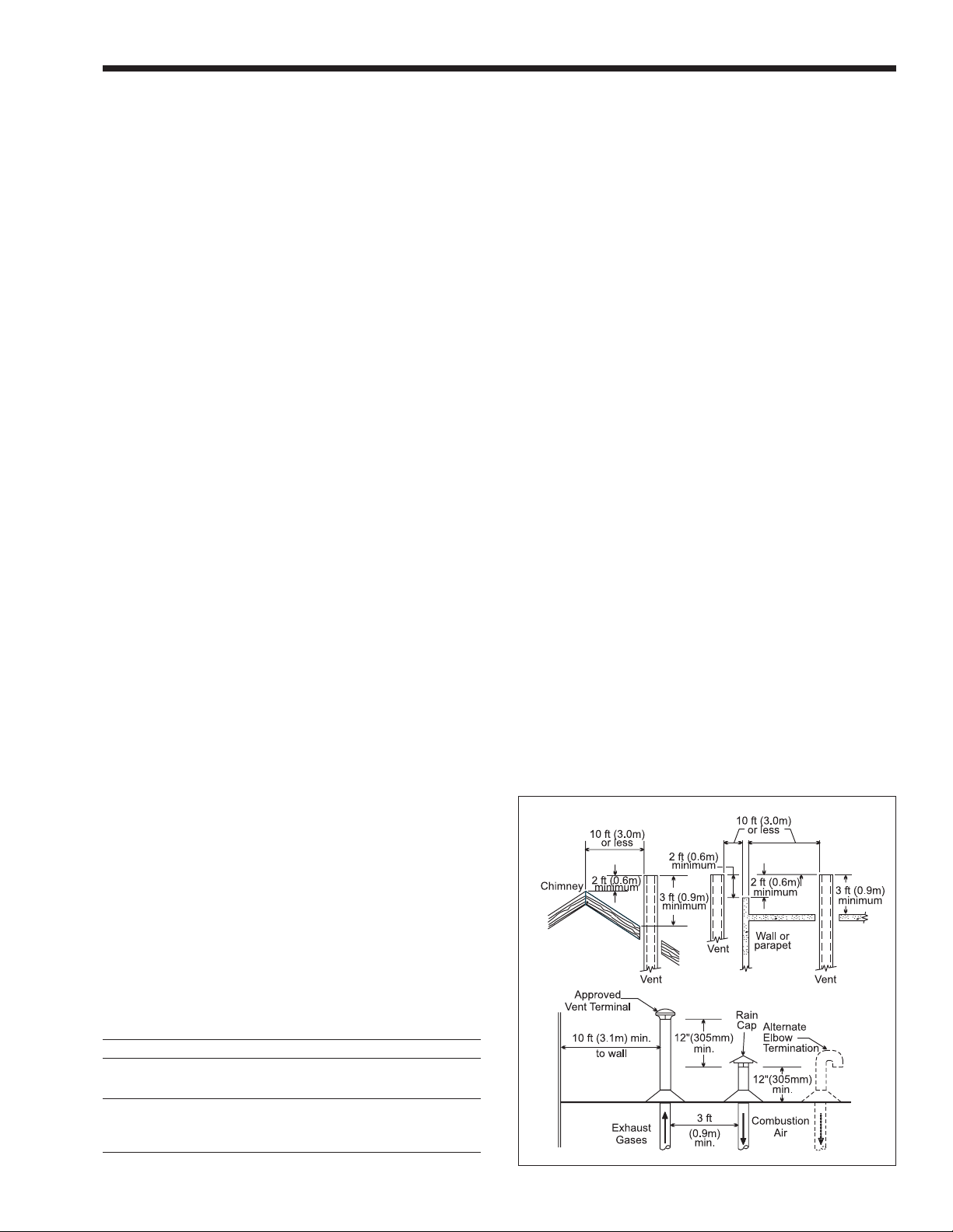
Figure 2. Combustion Air and Vent Through Roof.
Page 8

Page 8
LAARS Heating Systems
2.2.2 Category I Vent
When vented as a category I appliance, the vent
system must conform to the National Fuel Gas Code
(American National Standard Z223.1-Latest Edition)
in the U.S., or in Canada, to CSA B149.1 (latest
edition). The vent system must be sized and installed
for a Category I Fan-Assisted Appliance.
If chimney height is greater than 25 feet, or
if multiple units are vented into the same vertical
vent, a barometric damper must be installed on each
appliance, such that the ue draft does not exceed
(negative) 0.1" w.c.
If using a power venter for any type of Category
I venting, the draft should be set between (negative)
0.01 and 0.10" w.c.
2.2.3 Common Venting Systems
Pennant units are Category I fan-assisted when
vented vertically and adhering to all applicable codes.
Pennant units are not allowed to be vented into a
common horizontal vent system, unless a properly-
sized vent fan is used, and the common vent system
is properly designed by the vent fan manufacturer or
a qualied engineer.When common venting Pennant
fan-assisted heaters with other appliances through
one shared vertical duct called a “common vent”,
special care must be taken by the installer to ensure
safe operation. In the event that the common vent
is blocked, it is possible, especially for fan-assisted
devices, to vent backwards through non-operating
appliances sharing the vent, allowing combustion
products to inltrate occupied spaces. If the
appliances are allowed to operate in this condition,
serious injury or death may occur.
WARNING
Operation of appliances with a blocked common
vent may lead to serious injury or death. Safety
devices must be implemented to prevent blocked
common vent operation. If safe operation of all
appliances connected to a common vent cannot
be assured, including prevention of spillage of ue
gasses into living spaces, common venting should
not be applied, and appliances should each be
vented separately.
It is for this reason that, in addition to
following proper vent sizing, construction and safety
requirements from the National Fuel Gas Code,
ANSI Z223.1 or in Canada, from CSA B149.1 as
well as all applicable local codes, it is required that
installers provide some means to prevent operation
with a blocked common vent. It is suggested that a
blocked vent safety system be employed such that if
the switch from one appliance trips due to excessive
stack spill or backpressure indicating a blocked vent
condition, that all appliances attached to the vent be
locked out and prevented from operating. (Note that
the Pennant Pool Heater is equipped with a blocked
vent safety (pressure) switch, as shipped.) As an
additional precaution, it is recommended that a Carbon
Monoxide (CO) alarm be installed in all enclosed
spaces containing combustion appliances. If assistance
is required in determining how a blocked vent safety
system should be connected to a LAARS product,
please call Applications Engineering at the telephone
number on back cover of this manual.
Refer to the installation and operating
instructions on all appliances to be common vented
for instructions, warnings, restrictions and safety
requirements. If safe operation of all appliances
connected to a common vent cannot be assured,
including prevention of spillage of ue gasses into
living spaces, common venting should not be applied,
and appliances should each be vented separately.
2.2.4 Category III Vent
When the Pennant is vented with horizontal
discharge, it must be installed per this installation
manual and the venting system manufacturer’s
installation instructions. The vent system must be
sealed stainless steel, per Table 5.
Route the vent pipe to the heater as directly as
possible. Seal all joints and provide adequate hangers
as required in the venting system manufacturer’s
Installation Instructions. Horizontal portions of the
venting system must be supported to prevent sagging
and may not have any low sections that could trap
condensate. The unit must not support the weight of
the vent pipe. Horizontal runs must slope downwards
not less than ¼ inch per foot (2 cm/m) from the unit to
the vent terminal. Reference Table 1 for the size of the
Category III vent system. Up to three elbows can be
used with 50 linear feet (15.2m) of pipe. Subtract 10
allowable linear feet (3.0m) for every additional elbow
used.
2.3 Locating Vent & Combustion Air
Terminals
2.3.1 Side Wall Vent Terminal
The Laars side wall vent hood (listed in Table
1) must be used when the heater is vented through
a side wall. It provides a means of installing vent
piping through the building wall, and must be located
in accordance with ANSI Z223.1/NFPA 54 and
applicable local codes. In Canada the installation must
be in accordance with CAN/CGA B149.1 or .2 and
TERM DESCRIPTION
Pipe Must comply with UL Standard 1738
such as Type 29-4C Stainless Steel
(either insulated or non-insulated).
Joint Follow vent manufacturer’s instructions
Sealing
Table 5. Required Horizontal Venting Material.
Page 9
Pennant Pool Heater
Page 9
Figure 3. Combustion Air and Vent Through Side Wall.
local applicable codes (see Figure 3). Consider the
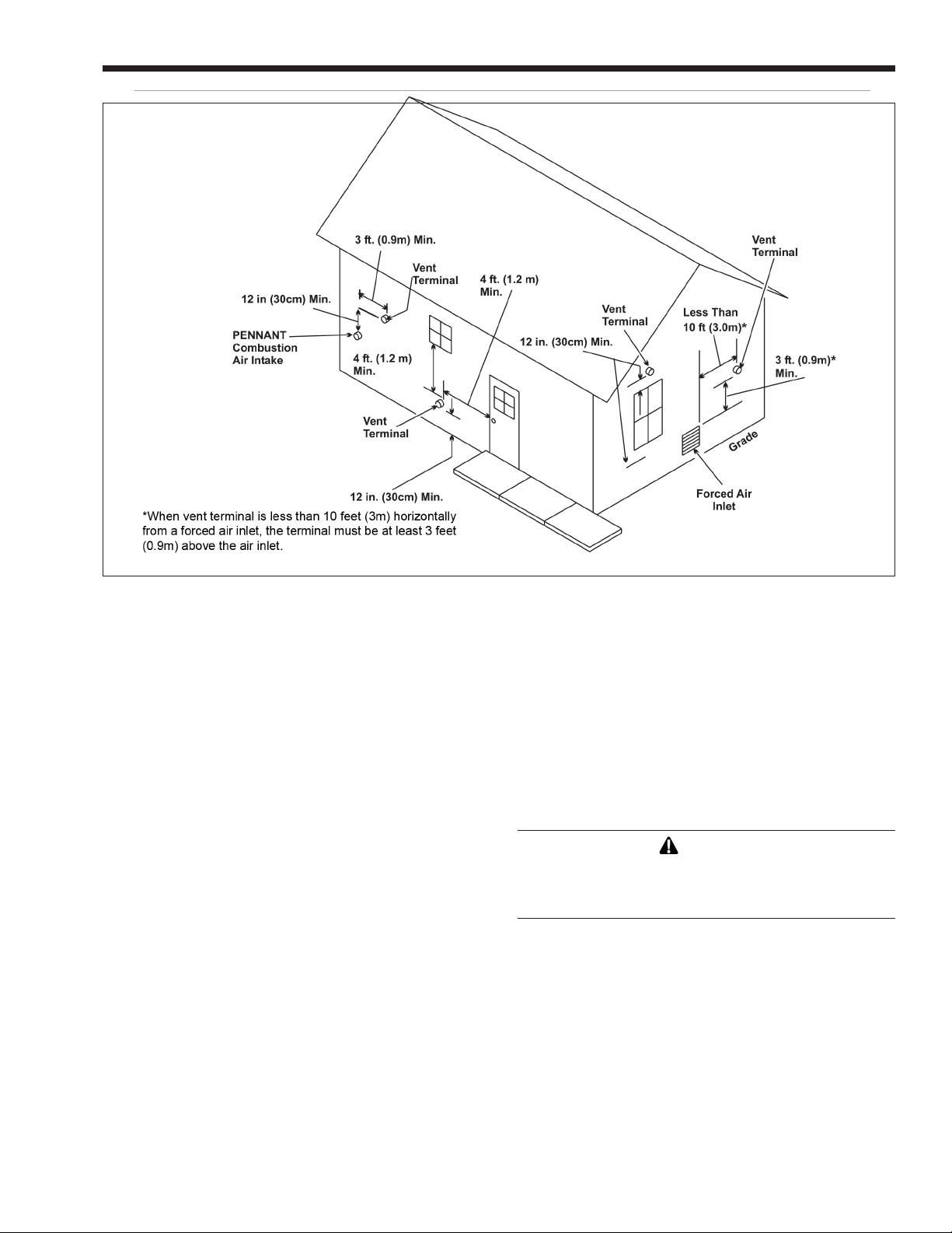
following when installing the terminal:
1. Through-the-wall vent terminals must terminate
at least 7-feet above a public walkway.
2. Locate the vent terminal so that vent gases cannot
be drawn into air conditioning system inlets. The
National Fuel Gas Code requires that it be at least
3 feet (0.9m) above any such inlet
that is within a horizontal distance of 10 feet (3m).
3. Locate the vent terminal so that vent gases cannot
enter the building through doors, windows,
gravity inlets or other openings. The National
Fuel Gas Code requires that it be located at least
4 feet (1.2m) below, 4 feet (1.2m) horizontally
from, or 1 foot (0.3m) above such openings.
Whenever possible, locations under windows or
near doors should be avoided.
4. Locate the vent terminal so that it cannot be
blocked by snow. The National Fuel Gas Code
requires that it be at least 12 inches (30 cm)
above grade, but the installer may determine
it should be higher, depending upon local
conditions.
5. Locate the terminal so the vent exhaust does
not settle on building surfaces and other nearby
objects. Vent products may damage such surfaces
or objects.
6. Locate the terminal at least 6 feet (1.8m)
horizontally from any gas or electric metering,
regulating, or relief equipment.
7. If the Pennant uses ducted combustion air from
an intake terminal located on the same wall,
locate the vent terminal at least 3 feet (0.9m)
horizontally from the combustion air terminal,
and locate the vent terminal at least 1 foot (0.3m)
above the combustion air terminal.
8. Note that side wall vent terminals for models
750-2000 are shipped with reducers for the vent
collars, to accommodate horizontal vent sizes,
shown in Table 1.
WARNING
The outdoor vent terminal gets hot. Unit must be
installed in such a way as to reduce the risk of
burns from contact with the vent terminal.
2.3.2 Side Wall Combustion Air Terminal
Never obtain combustion air from the pool area.
Corrosion of and/or damage to the pool heater may
result. The Laars side wall combustion air terminal
(listed in Table 1) must be used when the unit takes
its combustion air through a duct from a side wall.
Consider the following when installing the terminal:
1. Do not locate the air inlet terminal near a source
of corrosive chemical fumes (e.g., cleaning uid,
chlorinated compounds, etc.)
2. Locate the terminal so that it will not be subject
to damage by accident or vandalism.
3. Locate the combustion air terminal so that it
cannot be blocked by snow. The National Fuel
Page 10

Page 10
LAARS Heating Systems
Gas Code requires that it be at least 12 inches (30
cm) above grade, but the installer may determine
it should be higher, depending upon local
conditions.
4. If the Pennant is side-wall vented to the same
wall, locate the vent terminal at least 3 feet
(0.9m) horizontally from the combustion air
terminal, and locate the vent terminal at least 1
foot (0.3m) above the combustion air terminal
(see Figure 3).
2.3.3 Vertical Vent Terminal
When the unit is vented through the roof, the
vent must extend at least 3 feet (0.9m) above the point
at which it penetrates the roof. It must extend at least
2 feet (0.6m) higher than any portion of a building
within a horizontal distance of 10 feet (3.0m), and high
enough above the roof line to prevent blockage from
snow. When the combustion air is taken from the roof,
the combustion air must terminate at least 12" (30cm)
below the vent terminal (see Figure 2).
2.4 Vent Terminals for Outdoor Units
For outdoor applications, the vent and
combustion air openings must be covered with proper
terminals to prevent rain, snow and other objects from
falling into the Pennant.
Part numbers for the terminals to cover the vent
and combustion air openings are shown in Table
6. Vent opening must be on top of the unit, and the
combustion air opening must be on the back of the
unit. The terminals are connected directly to the unit.
No vent piping is used.
Alternately, the installer may use a short piece
of galvanized single wall or B-vent and an approved
rain cap for the vent termination. A minimum 12" of
vent height is acceptable. In addition, a properly sized
single wall galvanized 90° ell can be used for the
intake air terminal, with the open end of the ell facing
down to prevent rain inltration. The combustion air
inlet opening must still be high enough to prevent
blockage by snow (see Section 2.3.2).
2.3.4 Vertical Combustion Air Terminal
When combustion air is taken from the roof, a
eld-supplied rain cap or an elbow arrangement must
be used to prevent entry of rain water (see Figure 2).
The opening on the end of the terminal must be at least
12" (30cm) above the point at which it penetrates the
roof, and high enough above the roof line to prevent
blockage from snow. When the vent terminates on the
roof, the combustion air must terminate at least 12"
(30cm) below the vent terminal.
OUTDOOR VENT OUTDOOR
SIZE TERMINAL COMBUSTION
AIR TERMINAL
500 20254703 D2007900
750 20254705 D2007900
1000 20254705 D2008000
1250 D2007700 D2008000
1500 D2007700 D2008000
1750 D2007800 D2008000
2000 D2007800 D2008200
Table 6. Vent Terminals for Outdoor Units
Page 11
Pennant Pool Heater
Page 11
SECTION 3.
Gas Supply and Piping
3.1 Gas Supply and Piping
Gas piping should be supported by suitable
hangers or oor stands, not by the appliance.
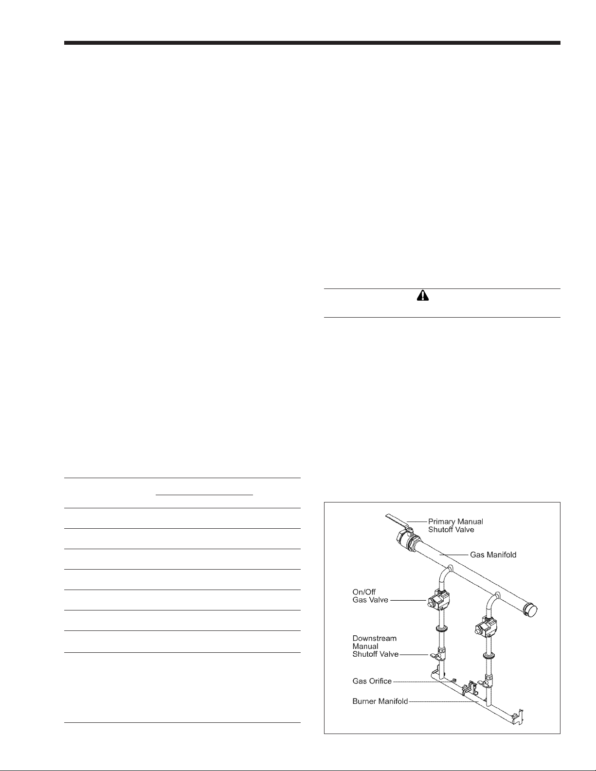
The Pennant’s gas train allows the user to pipe
the gas from either the right side or the left side of
the unit. As shipped, the right side of the gas train is
capped off, and there is a manual valve on the left side.
If desired, the manual valve on the left side of the gas
train may be moved to the right side, and the cap on
the right side may be moved to the left.
Review the following instructions before
proceeding with the installation.
1. Verify that the appliance is tted for the proper
type of gas by checking the rating plate. Laars
Heating Systems appliances are normally
equipped to operate at elevations up to 2000 feet
(610m). Pennant appliances may be adjusted to
operate properly at higher elevations; however,
input will be reduced if the heating value of the
gas supply is below sea level values.
2. The maximum inlet gas pressure must not exceed
13" W.C (3.2kPa). The minimum inlet gas
pressure is 5" W.C. (1.2kPa).
3. Refer to Table 7, size supply.
4. Run gas supply line in accordance with all
applicable codes.
5. Locate and install manual shutoff valves in
accordance with state and local requirements.
6. A sediment trap must be provided upstream of
the gas controls.
7. All threaded joints should be coated with
piping compound resistant to action of liqueed
petroleum gas.
8. The appliance and its individual shutoff valve
must be disconnected from the gas supply piping
during any pressure testing of that system at test
pressures in excess of 1/2 PSIG (3.45kpa).
9. The unit must be isolated from the gas supply
system by closing its individual manual shutoff
valve during any pressure testing of the gas
supply piping system at test pressures equal to or
less than 1/2 PSIG (3.45kpa).
10. The appliance and its gas connection must be
leak tested before placing it in operation.
11. Purge all air from gas lines.
Caution
Do not use open ame to check for leaks.
NOTE: The Pennant appliance and all other gas
appliances sharing the gas supply line must be ring
at maximum capacity to properly measure the inlet
supply pressure. The pressure can be measured at
the supply pressure port on the gas valve. Low gas
pressure could be an indication of an undersized
gas meter, undersized gas supply lines and/or an
obstructed gas supply line. The Pennant may not re if
the gas pressure lower than 5" w.c.
DISTANCE FROM GAS METER
SIZE AND
GAS TYPE 0-100' 0-31m 100-200' 31-61m 200-300' 61-91m
500 natural 1-1/2" 3.8cm 2" 5.1cm 2" 5.1cm
500 propane 1" 2.5cm 1-1/2" 3.8cm 1-1/2" 3.8cm
750 natural 2" 5.1cm 2" 5.1cm 2-1/2" 6.4cm
750 propane 1-1/2" 3.8cm 1-1/2" 3.8cm 2" 5.1cm
1000 natural 2" 5.1cm 2-1/2" 6.4cm 3" 7.6cm
1000 propane 1-1/2" 3.8cm 2" 5.1cm 2-1/2" 6.4cm
1250 natural 2-1/2" 6.4cm 2-1/2" 6.4cm 3" 7.6cm
1250 propane 2" 5.1cm 2" 5.1cm 2-1/2" 6.4cm
1500 natural 2-1/2" 6.4cm 3" 7.6cm 3" 7.6cm
1500 propane 2" 5.1cm 2-1/2" 6.4cm 2-1/2" 6.4cm
1750 natural 2-1/2" 6.4cm 3" 7.6cm 3" 7.6cm
1750 propane 2" 5.1cm 2-1/2" 6.4cm 2-1/2" 6.4cm
2000 natural 3" 7.6cm 3" 7.6cm 3-1/2" 8.9cm
2000 propane 2-1/2" 6.4cm 2-1/2" 6.4cm 3" 7.6cm
Notes:
1. These gures are based on 1/2" (0.12kPa) water column
pressure drop.
2. Check supply pressure and local code requirements before
proceeding with work.
3. Pipe ttings must be considered when determining gas pipe
sizing.
OR LAST STAGE REGULATOR
Table 7. Gas Piping Size.
Figure 4. Typical Gas Train Conguration.
Page 12
Page 12
LAARS Heating Systems
SECTION 4.
Water Connections
4.1 Piping
Hot water piping should be supported by suitable
hangers or oor stands. Do not support piping with
this appliance. Due to expansion and contraction of
copper pipe, consideration should be given to the type
of hangers used. Rigid hangers may transmit noise
through the system resulting from the piping sliding in
the hangers. It is recommended that padding be used
when rigid hangers are installed. Maintain 1" clearance
to combustibles for hot water pipes.
Pipe the discharge of the relief valve (full size) to
a drain or in a manner to prevent injury in the event of
pressure relief. Install shutoff valves where required by
code.
Pennant Pool Heaters are equipped with mounted
pumps, which serve the heater plus 30 feet of fullsized piping with a normal number of ttings. If the
pool’s loop is more than 15 feet away from the heater,
please contact the factory.
A mixing system is mounted on the heater. The
system consists of a three-way valve, temperature
control and piping. The temperature sensor for the
control is in the heater inlet. When the control detects
water temperature that is below 120°F (49°C), it will
direct the three-way valve to actuate, which sends
water from the outlet of the heater back to the inlet.
The outlet water that is diverted to the inlet mixes with
the return water from the pool, and keeps the inlet
temperature at or above 120°F (49°C) (see Figure 5).
This keeps cold return water from causing condensing
on the outside of the Pennant heat exchanger.
IMPORTANT NOTE: Since heater outlet temperatures
can reach 150°F (66°C) in some cases, copper
or CPVC are recommended materials for heater
connection piping. PVC material may be used for the
inlet valve and the piping upstream of it.
When pipe, ttings, grids or any other element
of the lter system are made of plastic materials, they
may be damaged by the momentary “back siphoning”
of hot water from the heater when the lter pump stops
running.
See Figure 6 for proper connection of the
Pennant heater to the pool loop.
4.2 Automatic Chlorinators
Figure 5. Mixing System.
The Pennant Pool Heater is shipped with a eld-installed mixing system, and must be piped in primarysecondary style, as shown. A remote pool temperature sensor and remote pool temperature high limit
are wired to the Pennant, to be mounted in the pool water loop, as shown.
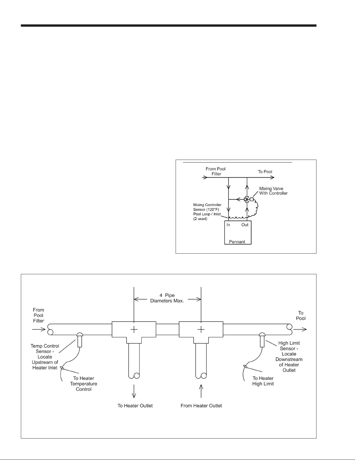
Figure 6. Pool Heater Piping.
Page 13

Pennant Pool Heater
Page 13
A concentration of chlorine in the heater can be
very destructive; therefore the following rules about
the installation and operation of such devices must be
followed:
1. The chlorinator should be installed so it
introduces the gas or solution downstream of the
heater.
2. The chlorinator should be wired so it cannot
operate unless the lter pump is operating.
3. The chlorinator should be provided with an anti-
siphon device so that the draining of the piping
after the pump shuts off will not siphon chlorine
solution into the heater.
4. When the operation of a chlorinator is such
that it must be installed in the pump suction, or
some other place where the chlorine solution
ows through the heater, corrosion of the
heater can occur. Excessive concentrations of
chlorine resulting from improper adjustment or
chlorinator equipment failure are responsible
for this corrosion. The heater warranty does not
cover the resulting damage to the heat exchanger.
4.3 Sensor Locations
Two sensors must be installed in the pool loop, as
shown in Figure 6. The inlet sensor for the temperature
control must be installed in the pool loop within 12”
(30 cm) of the inlet to the heater. This sensor is not
installed in a well. For sensitivity, it must be installed
in direct contact with the pool water ow. The second
sensor, the high limit sensor, must be installed in the
pool loop within 12” (30 cm) downstream of the heater
outlet. This sensor is a capillary and bulb. It shall be
used with the immersion well that is provided.
SECTION 5.
Electrical Connections
WARNING
The appliance must be electrically grounded in
accordance with the requirements of the authority
having jurisdiction or, in the absence of such
requirements, with the latest edition of the National
Electrical Code, ANSI/NFPA 70, in the U.S. and
with latest edition of CSA C22.1 Canadian Electrical
Code, Part 1, in Canada. Do not rely on the gas
or water piping to ground the metal parts of the
boiler. Plastic pipe or dielectric unions may isolate
the boiler electrically. Service and maintenance
personnel, who work on or around the boiler, may
be standing on wet oors and could be electrocuted
by an ungrounded boiler.
Single pole switches, including those of safety
controls and protective devices must not be wired in a
grounded line.
All electrical connections are made in the eld
wiring terminal strip, which is located at the right side
of the appliance.
NOTE: All internal electrical components have been
prewired. No attempt should be made to connect
electrical wires to any other location except the eld
wiring strip.
5.1 Main Power
5.1.1 Sizes 500-1500
Pennant pool heater sizes 500-1500 use a single
120-volt fused supply. The installer can change the
single service heaters to use a separate circuit for the
pump, if desired. Instructions to make this change are
found in Section 5.1.3.
Pennant 500-1500 main power (L1, N1 &
Ground) shall be connected to the three wires (10
AWG) supplied. Over-current protection ratings can be
found in Table 8.
5.1.2 Sizes 1750-2000
Pennant Sizes 1750-2000 require two 120-volt
fused supplies.
Heater circuit can be identied with 10AWG
wires to include black, white and green (all solid
colors). Pump circuit can be identied with three
12AWG wires to include a black wire with a white
tracer (stripe), a white and green wire.
5.1.3 Separate Pump Circuit
Conversion to separate pump circuit will
necessitate removing the three jumpers within
the internal wiring of the 120-volt portion of the
heater (see Figure 7). Only do this with the power
disconnected to the unit!
To rewire the pump circuit, bring in another
120-volt fused supply (L2, N2 & Ground). Connect
incoming power (L2) to the main power switch using
Page 14

Page 14
LAARS Heating Systems
spade (fork) terminal. From the other side of the main
power switch connect to the main terminal block using
a ¼" female insulated quick connect. This will be
the same position where the jumper had terminated
(see Figure 7). Connect N2 and Ground to the main
terminal block using ¼" female insulated quick
connect (refer to Figure 7).
5.1.4 Auxiliary Time Clock Wiring
If a time clock is used to control the pool lter
pump operation, a separate switch or relay must be
used to shut off the heater at least 15 minutes before
the lter pump is shut off. A remote switch or relay,
if installed, should be connected across the “Other
Ints” terminals on the eld-wiring terminal strip (see
Figure 9) after removing the factory-installed jumper
from those terminals. For manual shut off, a switch is
provided and identied with a label on the right side of
the heater.
All eld-installed electrical safety devices and
controllers may also be connected across the Pennant’s
“Other Ints” terminals after the factory-installed
jumper is removed. If a remote switch or relay
(mentioned above) is installed, the other eld-installed
electrical safety devices and controllers should be
wired in series with that switch or relay.
5.1.5 All Sizes
Wiring diagrams are shown in Section 10 in
Figures 13 through 17. Field wiring is shown in
Section 10 in Figure 18.
IMPORTANT NOTE: If the backwash operation is
manual the heater must be shut off manually during
backwashing.
5.2 Temperature (Operating) Control
The Pennant temperature control operates by
measuring the pool loop return temperature, before
the heater inlet piping. It is adjustable to a maximum
of 104° F and will prevent heater operation at return
temperatures above 104° F. It also controls the pool
heater pump and the temperature of the water entering
the heat exchanger. It also controls the Pennant pump
operation and the mixing system, which tempers the
water entering the heat exchanger to prevent damage
from condensation. The sensors for the control
are installed as shown in Figure 6 and Section 4.3,
Sensor Locations. The automatic mixing system
sensor, already installed, is shown in Figure 5. During
operation, the automatic mixing system diverts water
from the outlet to the inlet to “pre warm” the water to
a minimum inlet temperature of 120°F. This prevents
condensation from forming, which can damage the
heater.
5.3 Programming the Temperature
Control
5.3.1 Temperature Control Overview
The digital display on the control has the
following uses:
• To display the actual pool loop temperature
during normal operating mode.
• To allow the user to view and adjust the
control settings.
Figure 8 identies the control buttons.
The Pool Heater Temperature Control face
contains an LCD screen and four (4) buttons (see
Figure 8). The LCD screen will display the pool loop
return temperature during normal operation. When
the control is rst powered up, it displays . It
then displays the temperature at the pool loop sensor.
After the temperature is displayed, the current settings
(parameters) may be viewed. To scroll through the
parameters, press the down arrow button to advance to
the next parameter.
Figure 7. Removing Jumpers.
5.3.2 Programming Control Parameters
There are four (4) control parameters that may
be set. They are the Pool Loop Temperature (LSP), the
Pool Loop Temperature Differential (dLS), the Boiler
Temperature (bsp) and the Pump Off Delay (Pd).
The pool loop temperature (desired pool
temp-erature) is set by changing the LSP parameter.
After scrolling through the parameters until LSP is
displayed, press the enter button. The setpoint will be
displayed. Press the up arrow or down arrow buttons
until the desired setpoint is displayed. Press the
enter button and the setpoint will be activated. The
display will return to indicating the present pool loop
temperature.
In addition to the ability to set the pool loop
temperature, the differential associated with that
setting may also be adjusted. The differential is set by
Page 15

Pennant Pool Heater
Page 15
changing the dLS parameter. After scrolling through
the parameters until dLS is displayed, press the enter
button. The setpoint will be displayed. Press the up
arrow or down arrow buttons until the desired setpoint
is displayed. Press the enter button and the setpoint
will be activated. The display will return to indicating
the present pool loop temperature.
The boiler operating temperature is set by
changing the bsp parameter. After scrolling through
the parameters until bsp is displayed, press the enter
button. The setpoint will be displayed. Press the up
arrow or down arrow buttons until the desired setpoint
is displayed. Press the enter button and the setpoint
will be activated. The display will then return to
indicating the pool loop temperature.
The last parameter that may be adjusted is Pd,
the pump off delay. After again scrolling through the
parameters until Pd is displayed, press the enter button.
The pump delay time will be displayed. The pump off
delay may be set between 0.1 and 10 minutes. Press
the up arrow or down arrow buttons until the desired
setpoint is displayed. Press the enter button and the
setpoint will be activated. The display will again return
to indicating the present pool loop temperature.
By depressing the upper left hand button at
any time during the programming, the menu may be
returned to the beginning.
5.3.3 Setpoint - LSP
The setpoint is the desired temperature around
which the heater will control (desired pool temperature). It is adjustable between 60° F and 104° F.
SINGLE TWO CIRCUIT
SIZE CIRCUIT HEATER PUMP
500 20 15 15
750 20 15 15
1000 (TACO) 20 / (B&G) 30 20 15
1250 30 25 15
1500 30 25 15
1750 25 20
2000 25 20
Figure 8. Pool Heater Controller.
Table 8. Electrical Data (Amps).
Figure 9. Typical Control Panel.
Page 16

Page 16
LAARS Heating Systems
5.3.4 Differential - dLS
The differential (dLS) is the number of degrees
between the temperature at which the heater turns off
and the temperature at which the heater restarts. It is
adjustable from 1° F to 10° F.
5.3.5 Pump Operation
The pump energizes when there is a heat demand.
5.3.6 Heater Purge (Pump Delay) - Pd
After a demand is satised, the pump will
continue to run for a preset length of time. That length
of time is adjustable from 0.1 to 10 minutes and is
programmed by the parameter Pd.
Caution
Should overheating occur or the gas supply fail to
shut off, turn off the manual gas control valve to the
appliance.
5.4 Limit Controls
In addition to the pool heater temperature control,
Pennant appliances are tted with a Pool Loop high
limit set at 135° F and an automatic reset heater high
limit with a maximum setting of 190° F.
The Pool Loop high-limit sensing bulb is to be
installed in the sensor well (supplied), downstream of
the heater (see Figure 6). If sufcient capillary length
exists to reach the sensor location, the control may
remain in its location near the rear of the cabinet on
the right side, behind the slide out drawer (see Figure
9). If the sensor location is farther from the heater than
the capillary will reach to, then the control should be
moved to the remote location and the wires extended
to the new location of the control. If the controller
needs to be moved, and it is being moved to an
outdoor location, the control will need to be put in a
weather-tight enclosure to protect it from rain, snow,
etc.
The other limit control limits the temperature of
the discharge from the heat exchanger to a maximum
of 190° F. This limit should be set to a minimum of
175° F. To set the limit controls, remove the control
panel cover and pull the control panel out to gain
access. Appliances with reversed heat exchangers
have the limit controls relocated to the left side of the
appliance. The left access door must be removed to
gain access to the limit controls on these appliances.
SECTION 6.
Operating Instructions
6.1 Sequence of Operation
The amber “Ready” light on the front panel
indicates that the control system is energized. Upon
a call for heat from the pool temperature control, the
green “Heat” indicator on the front panel will light.
The green “Pump” indicator on the front panel
will light.
Once the water ow switch makes, and if all of
the safety interlocks are closed, the ignition module(s)
will energize the blower(s) for a 15-second pre-purge,
followed by a 20-second period to allow the ignitor(s)
to heat.
Energizing the blower pressurizes the air box
(which supplies air to the burners) and closes the
normally-open contact(s) of the airow pressure
switch(es). This allows the ignition module to proceed
with the ignition sequence.
The blocked ue pressure switch senses the
pressure difference between the exhaust plenum and
the blower inlet plenum. It will interrupt the airow
sensing circuit if this pressure exceeds a maximum
value. If airow is not proven, the ignition module
will either attempt ignition again (up to three times) or
will lockout (if the optional lockout ignition module is
used).
The ignition module checks that the ignitor
current has reached a minimum value and energizes
the gas valves at the end of the ignitor-heating period.
The green indicators on the front panel will light,
indicating that the gas valves are open.
After a 4-second trial for ignition, the ignitor
switches off, and unless the ame sensor detects
a ame, the gas valves will close and the ignition
module will either attempt ignition again (up to three
times) or will lockout (if the optional lockout ignition
module is used). Note: at this point, if gas pressure is
below the required 5" w.c. minimum, the pool heater
will lock out.
If ame is sensed, the burner will continue to
re as long as there is a call for heat. Pennant 1250,
1500, 1750 and 2000 models start at part load. When
the gas valves controlled by the rst ignition module
are energized, the second ignition module is energized
and enters the same ignition sequence just described.
If there is a subsequent loss of ame signal, the burner
will attempt re-ignition up to three times (only once
if optional lockout ignition module is used.) Loss of
ame signal from the rst ignition module will cause
shutdown of the heater.
When the call for heat is satised, the gas
valves close and the blower(s) continues to run for 30
seconds. The pump will continue to run for the length
of time selected at startup by the adjustment of the
pump time delay (Pd).
Page 17

Pennant Pool Heater
Page 17
If a call for heat is prevented from being satised
either by a safety interlock or due to an ignition
lockout, the red “Service” indicator on the front panel
will light. To reset the standard ignition module, toggle
the Pennant power switch off, and then on again. (To
reset the optional single try lockout ignition module,
the reset button on the module must be pressed.
Interrupting power to this module will not reset the
lockout.)
The Pennant 1250, 1500, 1750 and 2000 models
have two ignition modules that control different
burners.
6.2 Filling the Heater System
1. Ensure the system is fully connected, lled with
water and all valves are open.
2. Start up heater according to the procedure in this
manual. Operate the entire system for one (1)
hour.
3. After placing the unit in operation, the ignition
system safety shutoff device must be tested. First,
shut off the manual gas valve, and call the unit
for heat. After the pre-purge and ignitor heat-up
time, the main gas terminals will be energized,
attempting to light, for four (4) seconds, and
then will de-energize. The unit will go into
lockout mode. Second, turn the power off and
then on again, push the reset button (optional
Ignition Module only), open the manual gas
valve and allow the unit to light. While the unit is
operating, close the manual gas valve and ensure
that power to the main gas valve no longer exists.
4. Check the entire system for leaks.
Caution
Protect the heater from low pH water if an “acid
start up” or similar technique is used. Corrosion of
the heater and heat exchanger due to low pH water
is not covered under the limited warranty. The water
must be neutralized to normal pH levels before
lling the heater and starting up the system.
Important: The installer is responsible for identifying
to the owner/operator the location of all emergency
shutoff devices.
WARNING
Do not use this appliance if any part has been
under water. Immediately call a qualied service
technician to inspect the appliance and to replace
any part of the control system and any gas control
that may have been under water.
6.3 Operating the Burner and Set Up
6.3.1 Set Up for 0 to 2500 Feet Altitude
The setup must be checked before the unit is put
in operation. Problems such as failure to start, rough
ignition, strong exhaust odors, etc. can be due to
improper setup. Damage to the heater resulting from
improper setup is not covered by the limited warranty.
1. Using this manual, make sure the installation
is complete and fully in compliance with the
instructions.
2. Determine that the appliance and system are
lled with water and all air has been bled from
both. Open all valves.
3. Observe all warnings on the Operating
Instructions label and turn on gas and electrical
power to appliance.
4. Switch on the appliance power switch located on
the right side of the unit.
5. The Pennant will enter the start sequence, as long
as the unit is being called for heat. The blower
and pump come on for pre-purge, then the ignitor
warm-up sequence starts and after the ignitor
warm-up is complete and all safety devices are
veried, the gas valves open. If ignition doesn’t
occur, check that there is proper gas supply.
Wait 5 minutes and start the unit again. During
initial start up, air in the gas line may cause the
Pennant to "lock out" during the rst few trials
for ignition. Depending on the ignition modules
installed, the manual reset button on the ignition
module(s) may need to be depressed to restart the
heater.
6. When the unit is running, the supply gas pressure
must be checked. Inlet gas pressure must not
exceed 13" W.C. (3.2kPa). The minimum inlet
gas pressure is 5" W.C. (1.2kPa).
7. Once the inlet gas pressure is veried, the
outlet gas pressure from each valve (manifold
gas pressure) must be checked, and adjusted, if
necessary. The manifold gas pressure must be
2.5" W.C. (0.62kPa).
8. Complete the setup by checking the CO2 at the
outlet of the unit. The CO2 should be 8% for
natural gas, or 9.2% for propane.
9. After placing the appliance in operation, the
Burner Safety Shutoff Device must be tested.
To test:
(a) Close gas shutoff valve with burner
operating.
(b) The ame will go out and blower will
continue to run for the post purge cycle.
Three (3) additional attempts to light will
follow (only one (1) attempt for optional
module). Ignition will not occur as the gas
is off. The ignition control will lockout, and
will have to be reset before the unit will
operate. The ignition control reset button
is located on each ignition control, in the
lower right corner, and can be reset by
depressing. It is not marked on the ignition
control label.
(c) Open gas shutoff valve. Restart the
appliance. The ignition sequence will
start again and the burner will start. The
Page 18

Page 18
LAARS Heating Systems
appliance will return to its previous mode
of operation.
NOTE: Models 1250, 1500, 1750 and 2000 have two
ignition controls and two ignitors.
6.3.2 High Altitude Adjustment and Set Up
Pennant appliances may be operated at high
altitude (7700 ft., 2347 m) with a reduction in output
of approximately 10%. At elevations higher than 7700
ft. (2347 m) the reduction in output will exceed 10%
and at elevations below 7700 ft. (2347 m) it will be
less than 10%. When adjusted properly, the appliance
will perform properly at any altitude. High altitude
adjustment must not be made on appliances operating
at elevations below 2500 ft. (762 m).
No orice changes are required to adjust the
Pennant appliances for high altitude. High altitude
adjustment is accomplished by adjustment of the gas
valve manifold pressure and the air shutter(s). The
required instruments used to assist in these adjustments
are a CO2 or O2 Analyzer and a U-Tube Manometer or
other device capable of reading a pressure of 2.5-3.0
inches W.C. (0.62-0.75 kPa).
Start the adjustment process by checking the CO2
in the “as installed” condition. Adjust the air shutter(s)
so that the CO2 is about 8% or the O2 is about 6.8% for
appliances operating on Natural Gas. For appliances
operating on LP Gas adjust the air shutter(s) so that the
CO2 is about 9.2% or the O2 is about 6.8%. Appliances
with two blowers should be adjusted so that the air
shutters below each blower are open the same amount.
Once the CO2 or O2 has been set, the manifold
pressure may be adjusted. Remove the 1/8 NPT plug
from the lower side of the gas valve that is to be set
and install a tting, hose and manometer. Start the
appliance and observe the manifold pressure. Manifold
pressure must be adjusted to 3.0 in. W.C. (0.75 kPa)
(for high altitude only, standard operating pressure is
2.5 in. W.C. (0.62 kPa)). It is adjusted by removing the
slotted cap on the gas valve and turning the adjustment
screw (beneath the cap) clockwise to increase pressure
. After the adjustments have been completed, the t-
ting, hose and manometer have been removed and the
1/8" plug has been replaced, replace the cap. Repeat
this process until all gas valves have been set. Note:
The pressure can be set only when the appliance is
operating and only when the particular gas valve being
adjusted is energized by a call for heat.
After all of the gas valve manifold pressures
have been set, the CO2 or O2 must be reset. CO2 or O2
will have changed when the manifold pressure was
HEATER MINIMUM FILTER
MODEL PUMP FLOW RATE
PNCP 500 240 GPM
PNCP 750 360 GPM
Table 9. Minimum Filter Pump Flow Rates For Spas.
adjusted. Open the air shutter(s) to reduce the CO2 or
O2 to the values achieved previously.
The procedure is complete when all gas valves
are adjusted to a manifold pressure of 3.0 in. W.C.
(0.75 kPa) and the CO2 is adjusted to 8.0% for Natural
Gas appliances or 9.2% for LP appliances. When using
an O2 analyzer, the correct O2 is 6.8% for both Natural
Gas and LP appliances.
Caution
Should any odor of gas be detected, or if the gas
burner does not appear to be functioning in a
normal manner, close main shutoff valve, do not
shut off switch, and contact your heating contractor,
gas company, or factory representative.
6.4 Shutting Down the Pennant
1. Switch off the shutdown switch (located above
the Main Power Switch).
2. Wait until the “pump” light (located on the front
panel) goes out.
3. Switch off the main electrical disconnect switch.
4. Close all manual gas valves.
5. If freezing is anticipated, drain the Pennant and
be sure to also protect piping connected to the
Pennant from freezing.
This step to be performed by a qualied service person.
6.5 Backwash Switch Operation
Pennant Pool Heaters are equipped with a lter
backwash switch, which is located above the main
power switch. The switch is intended to provide a
means by which the heater can be safely shut down for
pool lter service, without causing nuisance tripping
of the heater high limit.
This switch is internally wired in series with the
Other Interlocks terminals, and will interrupt the call
for heat signal when open. Please note that when the
backwash switch is active the heater “Service” light
will be illuminated.
To place the heater into backwash mode proceed
as follows:
1. Turn the backwash switch down to the “Filter
Backwash Mode” position.
2. Wait for the heater outlet temperature to drop
down to a temperature equal to the pool water
return temperature.
3. Turn the main power switch off.
Pool lter servicing may now proceed normally.
After completion of the lter servicing, place the
heater back into service as follows:
1. Turn the main power switch on.
2. Allow time for the pump to turn on, and purge air
from the heater.
3. Turn the backwash switch up to the “Normal”
position.
Page 19

Pennant Pool Heater
Page 19
The service light will turn out, and the heater will
resume normal operation. Please note that if the heater
is equipped with a low water cut off there will be a
brief delay while the LWCO completes a self-check.
6.6 Spring and Fall Operation
Stand-by Service
Turn the thermostat down to approximately 70°F
(21°C). This will prevent the pool and surrounding
ground from becoming chilled and permit the pool to
be raised to swimming temperature in a shorter length
of time. Do Not Operate below 60°F (16°C).
6.7 Winter Operation
Complete Shutdown
1. See Section 6.4
2. If the heater is not protected from freezing
temperatures, it should be completely drained
before the rst frost. Drain the heater by
removing the plug at the end of the inlet/outlet
header casting. Also, remove the small plug at
the bottom of the pump housing. Do not replace
either plug until the time that relling is desired.
The heater must be level for complete draining.
When compressed air is used to blow out lines,
it is still necessary to follow these directions.
Because of the potential for electrical power
failure or pump failure, freeze protection should
never be accomplished by operating the pool
heater and the lter pump. Either of those failures
will potentially allow a freeze up and cause
damage to the heater and the attached system.
3. Improper use of the heater: The Laars PNCP
pool heater is not designed for continuous use as
a “anti-freezing” device for pools. Operating the
heater at low water temperatures will damage the
heat exchanger.
6.8 To Restart the Pennant
If drained, follow Section 6.2 in this manual for
proper lling and purging.
1. Switch off the main electrical disconnect switch.
2. Close all manual gas valves.
3. WAIT FIVE (5) MINUTES.
4. Set the pool aquastat to its lowest setting.
5. Open all manual gas valves.
6. Reset all safety switches.
7. Set the temperature controller to the desired
temperature setting and switch on electrical
power.
8. Burner will go through a prepurge period and
ignitor warm-up period, followed by ignition.
6.9 Therapeutic Pools (Spas)
Therapeutic pools or “spa” pools are usually
piped and controlled so that very warm or hot water,
often with air injection, is forced at high velocity
into a conned area of a swimming pool or into a
small separate pool. For the purposes of this manual,
any application in which the water temperature is
maintained above 85°F (30°C) is considered a spa.
SPECIAL SET-UP AND OPERATING
PROCEDURES APPLY TO SPAS.
1. Models PNCP1000 and larger should not be used
for spas due to their higher temperature rises.
2. To ensure that the spa inlet does not exceed 104°F
(40°C), the spa lter pump must circulate water
at the minimum ow rates shown in Table 9.
NOTE: Maximum Spa Temperature Is Assumed To Be
100°F (38°C).
3. Spas are excellent for relaxation, body-
conditioning and for arthritic and rheumatic
problems, but can be hazardous.
WARNING
The U. S. Consumer Product Safety Commission
has warned that elevated temperatures in spas and
hot tubs can be hazardous. Follow these “Safety
Rules for Hot Tubs:”
• Spa or hot tub water temperatures should never
exceed 104°F (40°C). A temperature of 100°F
(38°C) is considered safe for a healthy adult.
Special caution is suggested for young children.
• Drinking of alcoholic beverages before or during
hot tub use can cause drowsiness, which could
lead to unconsciousness and subsequently lead
to drowning.
• Pregnant women beware! Soaking in water
above 102°F (39°C) can cause fetal damage
during the rst three months of pregnancy
(resulting in the birth of a brain-damaged or
deformed child). Pregnant women should stick
to the 100°F (38°C) maximum rule.
• Before entering the spa or hot tub, users should
check the water temperature with an accurate
thermometer; spa or hot tub thermostats may
err in regulating water temperatures by as much
as 4°F (2°C).
• Persons with a medical history of heart disease,
circulatory problems, diabetes or blood pressure
problems should obtain their physician’s advice
before using spas or hot tubs.
• Persons taking medications which
induce drowsiness, such as tranquilizers,
antihistamines or anticoagulants, should not
use spas or hot tubs.
Page 20

Page 20
LAARS Heating Systems
SECTION 7.
Maintenance
7.1 System Maintenance
1. Lubricate the system water-circulating pump, if
required, per the instructions on the pump.
2. Inspect the venting system for obstruction or
leakage at least once a year. Periodically clean
the inlet air lter and the screens in the vent terminal and combustion air terminal (when used).
3. Keep the appliance area clear and free from
combustible materials, gasoline, and other
ammable vapors and liquids.
4. If the appliance is not going to be used for
extended periods in locations where freezing
normally occurs, it should be isolated from the
system and completely drained of all water. All
systems connected to it should also be drained or
protected from freezing.
5. Low water cutoffs, if installed, should be
checked every 6 months. Float type low water
cutoff should be ushed periodically.
6. Inspect ue passages, and clean with brushes/
vacuums, if necessary. Sooting in ue passages
indicates improper combustion. Determine the
cause and correct.
7. Inspect the vent system and air intake system,
and ensure that all joints are sealed properly. If
joints need to be resealed, completely remove
existing sealing material, and clean with alcohol.
Apply new sealing material, and re-assemble.
7.2 Appliance Maintenance and
Component Description
Only genuine Laars replacement parts should be used.
Caution
Label all wires prior to disconnection when servicing
controls. Wiring errors can cause improper and
dangerous operation. Verify proper operation after
servicing.
7.2.1 Burners
Close main manual gas valve before proceeding.
Checking the burners for debris - Remove the ignitor
inspection panels(s) and ignitor(s) and inspect the
burners through the ignitor hole(s) using a ashlight
to illuminate. If there is any indication of debris on
the burners that are visible, all the burners will need
to be inspected more thoroughly. Remove the screws
from around the front of the air box (large panel from
which the ignitor inspection panel(s) were removed),
and remove the large panel. Remove the gas manifold
assemblies and the burner panels. Inspect the burners.
Clean burners, if necessary, by blowing compressed
air from the outside of the burners into the center
of the burner. A dirty burner may be an indication
of improper combustion or dirty combustion air.
Determine the cause, and correct. Replace the burners
in the reverse order.
7.2.2 Filter
The lter used in the Pennant is washable with
an 83% arrestance. Since the lter is washable, it
will only need replacement in very rare cases. If lter
replacement is needed, it should only be replaced with
a factory part. Inspect the air lter. If there is debris on
the air lter, remove it from the lter box, and wash
it with mild soap and water. Ensure that the lter is
completely dry before re-installing, in reverse order.
7.2.3 Gas Valves
The gas valves are designed to operate with
supply pressures of 4-13 inches w.c. (1.0 to 3.2 kPa).
To remove a valve, shut off 120-volt power
and the manual gas shutoff valve. Remove the top
front panel from the unit. Disconnect the wires to the
valve. Disengage the anged tting before and after
the valve, and remove the valve. Re-install in reverse
order. Ensure o-rings are properly installed for both
inlet and outlet. Turn on manual gas shutoff valve and
120 volt power and check appliance operation and
tightness of gas valve connections.
For location of gas train and control components,
see Figures 4, 11 and 9, 12 respectively.
The gas and electric controls on the appliance
are engineered for long life and dependable operation,
but the safety of the equipment depends on their
proper functioning. It is strongly recommended that
a qualied service technician inspect the basic items
listed below every year.
a. Ignition controls
b. Ignitors
c. Water temperature control
d. Automatic gas valve
e. Pressure switches
f. Blowers
7.2.4 Pool Loop High Limit Control
The high limit switch is an automatic reset switch
with an adjustable set point, up to 135°F (57°C). To
replace the switch, shut off the 120-volt power to the
appliance. Remove the cover from the switch to access
the mounting screws. Remove the screws, and pull the
switch off the control panel. Remove the capillary and
bulb from the thermal well located in the pool loop
adjacent to the heater outlet. Replace in reverse order.
7.2.5 Automatic Reset High Limit Control
An automatic reset high limit is used to limit
heater water from exceeding 200°F. The high limit
switch has an adjustable set point, up to 190°F (88°C).
To replace the switch, shut off the 120-volt power
to the appliance. Remove the cover from the switch
Page 21

Pennant Pool Heater
Page 21
to access the mounting screws. Remove the screws,
and pull the switch off the control panel. Remove the
capillary and bulb from the thermal well located in the
header. Replace in reverse order.
7.2.6 Temperature Control
The temperature control is a single stage control.
To replace the control, shut off the 120-volt power to
the appliance. Unplug all of the electrical connectors,
remove the retainer clip and the control. Replace in
reverse order.
7.2.7 Ignition Controls
The ignition controls ensure the proved
interrupted-type ignition system. They control the
hot surface ignitor(s) and prove that the ame signal
is appropriate for powering the gas valves. It also
controls the blower’s pre-purge and post-purge.
Pennant sizess 500, 750 and 1000 have one ignition
control. Sizes 1250, 1500, 1750 and 2000 have two
ignition controls. On these models, one ignition
control provides for part-load start-up and the second
control brings the heater to full rate, after the rst
control has started the part-load burners.
To replace a control, shut off the 120-volt power
to the appliance. Remove the cover from the control
panel. Remove the electrical connectors from the
ignition control. Take out the controller’s mounting
screws, and pull the controller out. Replace in reverse
order.
7.2.8 Ignitors
The ignitors used are 120v “Hot Surface” type.
They are energized whenever there is a call for heat
and switched off when ignition is established and the
ame has been sensed. Pennant sizess 500, 750 and
1000 have one ignitor. Sizes 1250, 1500, 1750 and
2000 have two ignitors. To replace the ignitor, shut
off the 120- volt power to the appliance, remove the
ignitor access panel, disconnect the Molex connector,
remove the two mounting screws on the ignitor ange,
and pull the ignitor out. Install in reverse order, always
using a new ignitor gasket with the replacement
ignitor.
power. Unplug the transformer wires, remove the
mounting screws and remove the transformer. Replace
transformer in the reverse order.
7.2.11 Blowers
The combustion air blowers bring the combustion
air for the Pennant from the upper chamber to the
lower chamber. Mixing of the gas and air occurs in the
burners. If a blower change is required, turn off the
120-volt power and gas supply to the unit. Remove
the front panel. Disconnect the blower’s wire harness.
Remove the screws at the blower ange, and pull the
blower out. Replace blower in reverse order, ensuring
that all joints are made correctly. After replacement,
ensure that the unit operates properly, by following
the set-up procedure in this manual. Use caution in
handling the blower, ensuring you do not put pressure
on the blower wheel.
7.2.12 Flow Switch
The unit uses a paddle-type ow switch to en-
sure the unit has water ow before ignition is allowed.
7.2.13 Heat Exchanger Coil
Caution
Black carbon soot buildup on a dirty heat exchanger
can be ignited by a random spark or ame. To
prevent this from happening, dampen the soot
deposits with a wet brush or ne water spray before
servicing the heat exchanger.
The Pennant has a pre-mixed burner system.
These systems provide the burners with sufcient air
for complete combustion, and black carbon sooting is
seldom experienced. If sooting is suspected, view ports
for inspection of the heat exchanger are provided on
both sides of the heater. They are located below the
headers, and are accessed by opening the small round
cover that is attached by one screw. In the unlikely
event that there is a buildup of black carbon soot
or other debris on the heat exchanger, clean per the
following:
Caution
Ignitor gets hot.
7.2.9 Ignition Sensors
The ignition sensors ensure that the main ame
is ignited, so that raw gas is not allowed to ll the
combustion chamber. The ignitors are the ignition
sensors on Pennant appliances. There are no separate
ignition sensors.
7.2.10 Transformer
The Pennant’s transformer is not capable of
supplying control voltage for external devices. Should
a transformer need replacing, shut off the 120-volt
1. Disconnect the electrical supply to the unit.
2. Turn off the gas supply by closing the manual gas
valve on the heater.
3. Disconnect and remove the wires, conduit and
sensors from all components that are attached to
the inlet/outlet header.
4. Isolate the heat exchanger from the water supply.
5. Disconnect the header anges from the inlet and
outlet.
6. Allow the heat exchanger to drain. Remove
the front cover(s). Remove the venting and
remove the top, by removing the screws that
attach the top to the side panels. Remove the
Page 22

Page 22
LAARS Heating Systems
side panels. Remove the front lower panels
sealing the combustion area. To remove the
gas train, disconnect the unions located above
the intermediate pan and the eld installed
union located outside the cabinet, and pull up,
bringing the union end connectors through the
grommets in the intermediate pan. To remove
the intermediate pan, remove the slide out control
assembly and blower(s) to reveal the screws.
Remove the screws holding the intermediate pan,
and lift up to remove it. The heat exchanger has
integral metal sections attached, which connect
to the frame of the boiler. Locate and remove
the screws along the front, rear and bottom of
the integral metal sections, and remove the heat
exchanger and metal sections by lifting up. On
the larger appliances, a center heat exchanger
support must be unbolted before it can be
removed.
7. Remove the heat exchanger from the unit.
NOTE: The heat exchangers are heavy and will
require two people to remove to avoid personal injury.
8. Clean the heat exchanger: A light accumulation
of soot or corrosion on the outside of the heat
exchanger can be easily removed. Use a wire
brush to remove loose soot and scale from the
heat exchanger. Do not use water or compressed
air for cleaning.
9. NOTE: While the heat exchanger is out of the
unit, inspect the rewall refractory insulation.
Replace if necessary.
10. Inspect the inside of the copper tubes for scale
buildup. Scale can build up on the inner surface
of the heat exchanger tubes, which can restrict
water ow. If the tubes show signs of scaling,
clean the internal surface. Laars offers a tube
cleaning kit part number R0010000.
11. Reassemble in the reverse order, and check
appliance operation after start-up.
NOTE: The Warranty does not cover damage
caused by lack of required maintenance, lack of
water ow, or improper operating practices.
SECTION 8.
Trouble Shooting
8.1 Resolving Lockouts
There are many causes of lockouts. The three
most common causes are: (1) inadequate gas supply,
(2) poor combustion, (3) ignitor failure.
1. Inadequate gas supply: Before proceeding, ensure
that the gas supply has not been shutoff or the LP
tank (LP boilers) is not empty. Then, restart the
boiler and observe the operational cycle. After
a 15-second fan pre-purge, the ignitor will heat
up for 20 seconds, and then the unit will light.
If it does not, check the gas supply pressure to
the appliance, after resetting the appliance and
attempting another start-up. The gas pressure to
the appliance must be above 5" W.C. (1.2kPa)
throughout the entire start-up cycle. If it is not,
correct the supply problem (check gas valves or
supply piping). If the supply pressure is adequate,
consult the factory for assistance.
2. Poor Combustion: Poor combustion should be
suspected if there is a strong ue gas odor. The
odor may result from an improper gas/air ratio
(high or low O2 or CO2). Pennant appliances
operate best with 45% excess air (8% CO2 on
natural gas, 9.2% CO2 on LP). Check the CO2 of
the appliance and adjust if necessary.
3. Ignitor failure: If the boiler goes through a
normal start cycle but combustion does not
occur, and the gas pressure is at least 5" w.c.,
ignitor failure may be the cause. Check the
ignitor by unplugging it, allowing it to cool to
room temperature, and measuring the ignitor
resistance. It should be 50-80 ohms. If the
resistance is not 50-80 ohms, replace the ignitor.
If the resistance is correct, reset the boiler and
check for 120 VAC at the ignitor plug during
the start cycle. If there is no voltage, replace the
faulty ignitor wire harness or the ignition control.
8.2 Delayed Ignition - Possible Causes
A defective burner can cause a delayed ignition.
If the gas supply pressure is proper and the gas
valves are functioning properly, then burners should
be inspected. There should be no distortion or
perforations in the burners outside of the active burner
port area. Replace if indicated.
8.3 Short Cycling
Because of the large mass of pool systems, short
cycling should not exist. If it does, it will be caused
by insufcient ow in the pool loop. Check that there
is no blockage in the pool loop such as a plugged or
partially plugged pool lter.
Page 23

Pennant Pool Heater
Page 23
8.4 High Gas Consumption
Appliances operating with an improper air/
fuel ratio are very inefcient and consequently, have
very high gas consumption. Because efciency is
high when the CO2 is high (or O2 is low), appliances
operating with low CO2 or high O2 (especially LP
appliances) consume more gas. Adjust the CO2 or O2
for optimum efciency. If no combustion analyzing
equipment (CO2 or O2) is available then a proper
adjustment of the air/fuel ratio (CO2 or O2) cannot
be accomplished. However, by briey snifng the
ue gases it is possible to determine if the CO2 or
O2 is within the proper range. No signicant ue gas
odor should be detected when combustion is proper.
A strong piercing smell indicates poor combustion
and generally a lean mixture - low CO2 or high O
The CO2 should be 8% (natural gas, 9.2% LP) at high
re. To check the CO2, rst verify that the supply gas
pressure is within 5" to 13" w.c. (1.2 to 3.2 kPa) With
the Pennant running with both stages ring, set the
air box pressure to 1.5" w.c. (0.37 kPa) (as a starting
point), by adjusting the air shutter(s) at the bottom of
the fan(s). Check the CO2, and adjust the air shutters if
further adjustment to the CO2 is needed. Sizess 1250,
1500, 1750 and 2000 have two blowers and two air
chambers (boxes). The pressure of each air box must
be equal when the nal adjustment is made.
.
2
The 24V power to the T’STAT terminal of the ignition
module(s) are routed through the safety interlocks.
The ladder diagram for sizess 1250, 1500, 1750
and 2000 is shown in Figure 14. These models have
two ignition modules, each with its own blower, and
each controlling part of the input so that startup at
reduced input is provided. The blowers are energized
by the ignition modules indirectly via switching relays.
When either ignition module receives a call for heat, it
switches its blower to high speed and the blower of the
idle ignition module to low speed.
The wiring schematic for the Pennant 500 – 1000
is shown in Figure 15, and the schematic for the 1250
– 2000 models is shown in Figures 16 and 17. All
24V wiring is routed through the diagnostic PC board.
Wiring harnesses connect between the diagnostic PC
board and the control components, indicator board,
or eld wiring terminal strip. The diagnostic board
contains LEDs that indicate open status of the safety
interlocks, and quick-connect terminals that provide
tests points for checking voltage/continuity at various
points in the control circuit.
Certain control elements that may need to be
rewired in the eld are connected via the eld wiring
terminal strip rather than to the diagnostic PC board.
These include the low-water cutoff (LWCO), external
alarm, and water ow switch.
8.5 Troubleshooting the Pool Heater
Temperature Control
With a Voltmeter, test for 24 VAC between
terminals 1 & 2 on the 10 pin connector. Check that
the sensor temperature is lower than the setpoint
temperature by at least the differential setting. If this
is true, check that there is 24 VAC at the yellow wire
on the 4 pin connector. If there is not 24 VAC, check
that the high limit is not open. If there is 24 VAC at the
yellow wire on the 4 pin connector and not at the light
blue wire on that connector, replace the control.
8.6 Troubleshooting Pennant Controls
The Pennant series consists of three sizes with
one ignition module (500, 750 & 1000) and four sizess
with two ignition modules (1250, 1500, 1750 and
2000).
A diagnostic panel, that includes test points, as
well as diagnostic lights, is provided in the control
module. It is located on the right side of the module,
behind the display. To access, remove the retaining
screws from the display cover panel and remove
it. Grasp the control module at its base and pull it
outward. Ladder diagrams are shown in Figures 13 and
14.
Figure 13 shows the diagram for the 500, 750 &
1000. These have one blower and one ignition module.
The blower is energized directly through the “inducer”
terminals F1 and F2 of the (Fenwal) ignition module.
SECTION 9.
Replacement Parts
Only genuine Laars replacement parts should be used.
9.1 General Information
To order or purchase parts for the Laars Pennant,
contact your nearest Laars dealer or distributor. If
they cannot supply you with what you need, contact
Customer Service (see back cover for address,
telephone and fax numbers).
9.2 Parts List
See next page.
Page 24

Page 24
LAARS Heating Systems
Item Description Size Size Size Size Size Size Size
500 750 1000 1250 1500 1750 2000
Sheet Metal Components
See Figure 10
1 Panel, Jacket, Side Left 5C3420 5C3420 5C3420 5C3420 5C3420 5C3420 5C3420
2 Panel, Jacket, Side Right 5C3526 5C3526 5C3526 5C3526 5C3526 5C3526 5C3526
3 Panel, Jacket, Front 5C3320 7C3320 10C3320 12C3320
3 Panel, Jacket, Front, Left 15C3320 17C3320 20C3320
4 Panel, Jacket, Front, Right 15C3320 17C3320 20C3320
5 Panel, Jacket, Rear 5C3220 7C3220 10C3220 12C3220 15C3220 17C3220 20C3220
5A Panel, Jacket, Rear, Filter Enclosure 15C3026 15C3026 15C3026
6 Panel, Jacket, Top 5C3021 7C3021 10C3021 12C3021
Panel, Jacket, Top, Left 15C3021 17C3021 20C3021
7 Panel, Jacket, Top Right 15C3025 17C3025 20C3025
8 Control Door, Access 5C3011 5C3011 5C3011 5C3011 5C3011 5C3011 5C3011
9 Plate, Gas Pipe Seal 5C3304 5C3304 10C3304 20C3304 20C3304 20C3304 20C3304
(2) (2) (2) (2) (2) (2) (2)
10 Plate, Cover, Wiring 5C3502 5C3502 5C3502 5C3502 5C3502 5C3502 5C3502
11 Plate, Vent 5C3004 10C3004 10C3004 20C3004 20C3004 20C3004 20C3004
12 Cover, Vent Plate 20C3006 20C3006 20C3006 20C3006
13 Plate, Cover, Filter 5C3002 5C3002 5C3002 15C3002 15C3002 15C3002 15C3002
14 Collar, Vent 5C3106 10C3100 10C3100 15C3100 15C3100 20C3100 20C3100
15 Air Filter Assembly 5C3700 5C3700 10C3700 15C3700 15C3700 15C3700 20C3700
16 Air Filter R2014700 R2014700 R2014700 R2014700 R2014700 R2014700 R2014700
(1) (1) (1) (2) (2) (2) (2)
16A Trim, Jacket, Front 5C3019 7C3019 10C3019 12C3019 15C3019 17C3019 20C3019
16B Housing, Rain Shield, Pump 5F3015 5F3015 5F3015 5F3015 5F3015 5F3015 5F3015
16C Cover, Housing, Pump 5F3016 5F3016 5F3016 5F3016 5F3016 5F3016 5F3016
16D Bracket, Support, Pump Cover 5F3017 5F3017 5F3017 5F3017 5F3017 5F3017 5F3017
Internal Components
See Figures 11 and 12
17 Base Assembly 5C1020 7C1020 10C1020 12C1020 15C1020 17C1020 20C1020
18 Chamber, Front 5C2003 7C2003 10C2003 12C2003 15C2003 17C2003 20C2003
18A Chamber, Left Side, Front 5C2015 5C2015 5C2015 5C2015 5C2015 5C2015 5C2015
18B Chamber, Right Side, Front 5C2016 5C2016 5C2016 5C2016 5C2016 5C2016 5C2016
Page 25

Pennant Pool Heater
Page 25
Size Size Size Size Size Size Size
19 Chamber, Rear 5C2006 7C2006 10C2006 12C2006 15C2006 17C2006 20C2006
Item Description 500 750 1000 1250 1500 1750 2000
20 Chamber Assembly, Left, Bottom 5C2601 5C2601 5C2601 5C2601 5C2601 5C2601 5C2601
21 Chamber Assembly, Right, Bottom 5C2201 5C2201 5C2201 5C2201 5C2201 5C2201 5C2201
22 Chamber, Top 5C2001 7C2001 10C2001 12C2001 15C2001 17C2001 20C2001
23 Chamber, Side, Top 5C2002 5C2002 5C2002 5C2002 5C2002 5C2002 5C2002
24 Exhaust Plenum 5C2007 10C2007 10C2007 20C2007 20C2007 20C2007 20C2007
25 Bracket, Chamber, Front 5C2009 7C2009 10C2009
Bracket, Chamber, Front Left 12C2011 15C2011 17C2011 20C2011
26 Bracket, Chamber, Front Right 12C2009 15C2009 17C2009 20C2009
27 Divider, Chamber, Front 15C2010 20C2002
27A Divider, Upper, Chamber, Front 15C2005 15C2005
27B Divider, Lower, Chamber, Front 15C2002 15C2002
28 Cover, Chamber 5C2004 7C2004
Cover, Chamber, Front Left 10C2004 12C2010 15C2004 17C2010 20C2010
29 Door, Chamber Access 5C2005 5C2005 5C2005 5C2005 5C2005 5C2005 5C2005
(1) (1) (1) (2) (2) (2) (2)
30 Cover, Chamber, Front Right 12C2008 15C2004 17C2008 20C2008
Gasket Tape, Rear, Base (43') R2014500 R2014500 R2014500 R2014500 R2014500 R2014500 R2014500
Gasket Tape, Front, Base (63') R2014600 R2014600 R2014600 R2014600 R2014600 R2014600 R2014600
32 Ignitor, Hot Surface, with Gasket 2400-286 2400-286 2400-286 2400-286 2400-286 2400-286 2400-286
(1) (1) (2) (2) (2) (2) (2)
33 Tile, Side (Right and Left) T2015601 T2015601 T2015601 T2015601 T2015601 T2015601 T2015601
(2) (2) (2) (2) (2) (2) (2)
34 Tile, Front T2017300
(1)
35 Tile, Front, Left Side T2016200 T2016800 T2016800 T2016800 T2016800 T2016800
(1) (1) (1) (1) (1) (1)
35A Tile, Front, Right Side T2016300 T2017100 T2017900 T2017100 T2017900 T2017100
(1) (1) (1) (1) (1) (1)
35B Tile, Front, Center T2016900 T2016900 T2016900 T2016900
(1) (1) (2) (2)
36 Tile, Rear T2015700
(1)
37 Tile, Rear, Left Side T2017500 T2016600 T2016600 T2016600 T2016600 T2016600
(1) (1) (1) (1) (1) (1)
Page 26

Page 26
LAARS Heating Systems
Size Size Size Size Size Size Size
Item Description 500 750 1000 1250 1500 1750 2000
37A Tile, Rear, Right Side T2016600 T2016600 T2018100 T2016600 T2018100 T2016600
(1) (1) (1) (1) (1) (1)
37B Tile, Rear, Center T2017200 T2017200 T2017200 T2017200
(1) (1) (2) (2)
38 Tile, Bottom T2015500
(1)
39 Tile, Bottom, Left Side T2017400 T2017400 T2017400 T2017400 T2017400 T2017400
(1) (1) (1) (1) (1) (1)
39A Tile, Bottom, Right Side T2016500 T2017400 T2018000 T2017400 T2018000 T2017400
(1) (1) (1) (1) (1) (1)
39B Tile, Bottom, Center T2015900 T2015900 T2015900 T2015900
(1) (1) (2) (2)
41 Heat Exchanger, Copper R2014901 R2014902 R2014903 R2026701 R2014904 R2026702 R2014905
Heat Exchanger, Cupro-Nickel R2027801 R2027802 R2027803 R2027804 R2027805 R2027806 R2027807
42 Water Barrier, Inlet/outlet 20230103 20230103 20230103 20230103 20230103 20230103 20230103
43 Water Barrier, Inlet 10338300 10338300 10338300 10338300 10338300 10338300 10338300
44 Gasket, Header S0095100 S0095100 S0095100 S0095100 S0095100 S0095100 S0095100
(2) (2) (2) (2) (2) (2) (2)
45 Cover, In/Out, Glass-Lined Cast Iron 10364504 10364504 10364504 10364504 10364504 10364504 10364504
Cover, In/Out, Bronze 10364501 10364501 10364501 10364501 10364501 10364501 10364501
46 Well, Temperature Control RE2058300 RE2058300 RE2058300 RE2058300 RE2058300 RE2058300 RE2058300
47 Gasket, Flange S0063700 S0063700 S0063700 S0063700 S0063700 S0063700 S0063700
(2) (2) (2) (2) (2) (2) (2)
48 Flange, Cast Iron 10391302 10391302 10391302 10391302 10391302 10391302 10391302
Flange, Bronze 20255401 20255401 20255401 20255401 20255401 20255401 20255401
49 Relief Valve, PNCH, 75 PSI A0063300 A0063600 A0063600 A0063600 A0063600 A0002700 A0002700
Relief Valve, PNCV, 125 PSI RA0001200 RA0001200 RA0001200 RA0001200 A0064400 A0064400 A0066400
50 Tee, Adapter, Outlet, Cast Iron 20150302 20150302 20150302 20150302 20150302 20150313 20150313
Tee, Adapter, Outlet, Bronze 20150301 20150301 20150301 20150301 20150301 20150301 20150303
51 Flow Switch RE0013000 RE0013000 RE0013000 RE0013000 RE0013000 RE0013000 RE0013000
52 Gauge, Temperature/Pressure RA0079000 RA0079000 RA0079000 RA0079000 RA0079000 RA0079000 RA0079000
54 Low Water Cutoff E2076500 E2076500 E2076500 E2076500 E2076500 E2076500 E2076500
55 Pump Housing, Glass-lined, Cast Iron R20607600 R20607600 R20607600 R20607600 R20607600 R20607600 R20607600
Pump Housing, Bronze 10483300 10483300 10483300 10483300 10483300 10483300 10483300
56 Gasket, Pump Adapter not used on current production (was S0024600)
Page 27

Pennant Pool Heater
Page 27
57 Pump Adapter, Glass-lined Cast Iron not used on current production (was 10364200)
Pump Adapter, Bronze 10364201 10364201 10364201 10364201 10364201 10364201 10364201
58 Bafe,Diffuser,PumpInlet 10338400 10338400 10338400 10338400 10338400 10338400 10338400
59 Pressure Switch RE0240900 RE0240900 RE0240900 RE0240900 RE0240900 RE0240900 RE0240900
(2) (2) (2) (3) (3) (3) (3)
60 Blower R2060900 R2060900 R2060900 R2060900 R2060900 R2060900 R2060900
(1) (1) (1) (2) (2) (2) (2)
61 Weldment, Blower Mount 5C5300 5C5300 5C5300 5C5300 5C5300 5C5300 5C5300
(1) (1) (1) (2) (2) (2) (2)
Size Size Size Size Size Size Size
Item Description 500 750 1000 1250 1500 1750 2000
62 Damper,DuctAssembly,Blower 15C5400 15C5400 15C5400 15C5400
(2) (2) (2) (2)
Electrical Components
See Figure 12A
64 Bracket, Control Panel Mounting 5C7103 5C7103 5C7103 5C7103 5C7103 5C7103 5C7103
65 Terminal Board, Field Wiring E2307400 E2307400 E2307400 E2307400 E2307400 E2307400 E2307400
66 IgnitionControl,SingleTry,CSD-1 E2107300 E2107300 E2107300 E2107300 E2107300 E2107300 E2107300
(1) (1) (2) (2) (2) (2) (2)
66A IgniltionControl,3-Try,non-CSD-1 E2313900 E2313900 E2313900 E2313900 E2313900 E2313900 E2313900
(1) (1) (2) (2) (2) (2) (2)
67 DiagnosticBoard E2105500 E2105500 E2105500 E2105500 E2105500 E2105500 E2105500
68 Indicator Light Panel Board E2105600 E2105600 E2105600 E2105600 E2105600 E2105600 E2105600
69 Temperature Control E2321700 E2321700 E2321700 E2321700 E2321700 E2321700 E2321700
70 High Limit, Auto Reset, 200°F E2217700 E2217700 E2217700 E2217700 E2217700 E2217700 E2217700
71 High Limit, Auto Reset, 135°F E2104800 E2104800 E2104800 E2104800 E2104800 E2104800 E2104800
72 Relay,Pump(SPST) E0098300 E0098300 E0098300 E0098300 E0098300 E0098300 E0098300
Relay,Fan(DPDT) E0076600 E0076600 E0076600 E0076600
(2) (2) (2) (2)
74 Transformer E2310400 E2310400 E2310400 E2312800 E2312800 E2312800 E2312800
(2) (2) (2) (2)
75A CircuitBreaker(non-CSD-1) E22106200 E22106200 E22106200 E2318800 E2318800 E2318900 E2318900
CircuitBreaker,CSD-1 E22106200 E2318800 E2318800 E2318900 E2318900 E2318900 E2318900
75B Switch, Rocker, 30A, 125VAC E2343300 E2343300 E2343300 E2343300 E2343300 E2343300 E2343300
Sensor, Temp Control E2314300 E2314300 E2314300 E2314300 E2314300 E2314300 E2314300
Page 28

Page 28
LAARS Heating Systems
Size Size Size Size Size Size Size
Item Description 500 750 1000 1250 1500 1750 2000
Gas Train Components
See Figure 10
76 Manifold, Gas Supply 5C6700 7C6700 10C6700 12C6700 15C6700 17C6700 20C6700
77 Valve, Ball V2003100 V2003100 R2003700 R2011600 R2011600 R2011600 R2011600
Burner Trays
Note: Burner Tray Assemblies contain item numbers 78 through 81.
Burner Manifold Assy, 3 Burners, Right, Nat 5C6600 5C6600 5C6600 5C6600 5C6600
(1) (1) (2) (1) (1)
Burner Manifold Assy, 3 Burners, Left, Nat 5C6500 5C6500 5C6500 5C6500 5C6500
(1) (2) (3) (1) (2)
Burner Manifold Assy, 4 Burners, Right, Nat 10C6600 10C6600 10C6600 10C6600
(1) (1) (1) (2)
Burner Manifold Assy, 4 Burners, Left, Nat 10C6500 10C6500 10C6500 10C6500
(2) (2) (2) (4)
Burner Manifold Assy, 3 Burners, Right, LP 5C6620 5C6620 5C6620 5C6620 5C6620
(1) (1) (2) (1) (1)
Burner Manifold Assy, 3 Burners, Left, LP 5C6520 5C6520 5C6520 5C6520 5C6500
(1) (1) (3) (1) (2)
Burner Manifold Assy, 4 Burners, Right, LP 10C6620 10C6620 10C6620 10C6620
(1) (1) (1) (2)
Burner Manifold Assy, 4 Burners, Left, LP 10C6520 10C6520 10C6520 10C6520
(2) (2) (2) (4)
78 Valve, Gas, Combination V2017600 V2017600 V2017600 V2017600 V2017600 V2017600 V2017600
(2) (3) (3) (5) (5) (6) (6)
79 Valve, Manual Shutoff V2000200 V2000200 V2000200 V2000200 V2000200 V2000200 V2000200
(2) (3) (3) (5) (5) (6) (6)
80 Orice, Gas, Natural L2013000 L2013000 L2013000 L2013000 L2013000 L2013000 L2013000
(6) (9) (12) (15) (18) (21) (24)
Orice, Gas, Propane L2012400 L2012400 L2012400 L2012400 L2012400 L2012400 L2012400
(6) (9) (12) (15) (18) (21) (24)
81 Burner Manifold, 3 Burners, Right L2012900 L2012900 L2012900 L2012900 L2012900
(1) (1) (2) (1) (1)
Burner Manifold, 3 Burners, Left L2012800 L2012800 L2012800 L2012800 L2012800
Page 29

Pennant Pool Heater
Page 29
Size Size Size Size Size Size Size
(1) (2) (3) (1) (2)
Item Description 500 750 1000 1250 1500 1750 2000
Burner Manifold, 4 Burners, Right L2012700 L2012700 L2012700 L2012700
(1) (1) (1) (2)
Burner Manifold, 4 Burners, Left L2012600 L2012600 L2012600 L2012600
(2) (2) (2) (4)
82 Burner Tray, 3 Burners L2012200 L2012200 L2012200 L2012200 L2012200
(2) (3) (5) (2) (3)
Burner Tray, 4 Burners L2012500 L2012500 L2012500 L2012500
(3) (3) (3) (6)
82A Gasket, Burner Tray, 3 Burner S2012700 S2012700 S2012700 S2012700 S2012700
(2) (3) (5) (2) (3)
Gasket, Burner Tray, 4 Burner S2012500 S2012500 S2012500 S2012500
(3) (3) (3) (6)
Page 30

Page 30
LAARS Heating Systems
Figure 10. Sheet Metal Components.
Page 31

Pennant Pool Heater
Page 31
Figure 11. Internal Components.
Page 32

Page 32
Enlargement
from previous
page
LAARS Heating Systems
A
Figure 12. Heat Exchanger Components.
Page 33

Pennant Pool Heater
SECTION 10.
Wiring Diagrams
Page 33
Figure 13. Pennant 500 - 1000 Ladder Diagram.
Page 34

Page 34
LAARS Heating Systems
Figure 14. Pennant 1250 - 2000 Ladder Diagram.
Page 35

Pennant Pool Heater
Page 35
Figure 15. Pennant 500 - 1000 Wiring Schematic.
Page 36

Page 36
LAARS Heating Systems
Figure 16. Pennant 1250 - 1500 Wiring Schematic.
Page 37

Pennant Pool Heater
Page 37
Figure 17. Pennant 1750 - 2000 Wiring Schematic.
Page 38

Page 38
LAARS Heating Systems
Figure 18. Field Wiring.
Page 39

Pennant Pool Heater
Page 39
Page 40

Dimensions and specications subject to change without notice in accordance with our policy of continuous product improvement.
800.900.9276 • Fax 800.559.1583 (Customer Service, Service Advisors & Technical Support)
20 Industrial Way, Rochester, NH 03867 • 603.335.6300 • Fax 603.335.3355 (Applications Engineering)
1869 Sismet Road, Mississauga, Ontario, Canada L4W 1W8 • 905.238.0100 • Fax 905.366.0130
www.Laars.com Litho in U.S.A. © Laars Heating Systems 1306 Document 3164E
H2311900E
 Loading...