

Page 1
Installation and Operation Instructions Document 1330E
Installation and Operation
Instructions for
®
with Touchscreen Display
Modulating Boilers and
Volume Water Heaters
Outdoor models
NTH & NTV
Sizes 150 – 850 MBTU/h
Indoor models
NTH Sizes 285 – 850 MBTU/h
NTV Sizes 150 – 850 MBTU/h
FOR YOUR SAFETY: This product must be installed and serviced by a professional service technician,
qualied in hot water boiler and heater installation and maintenance. Improper installation and/or operation
could create carbon monoxide gas in ue gases which could cause serious injury, property damage, or
death. Improper installation and/or operation will void the warranty.
WARNING
If the information in this manual is not
followed exactly, a re or explosion may
result causing property damage, personal
injury or loss of life.
Do not store or use gasoline or other
ammable vapors and liquids in the vicinity
of this or any other appliance.
WHAT TO DO IF YOU SMELL GAS
• Do not try to light any appliance.
• Do not touch any electrical switch; do not
use any phone in your building.
• Immediately call your gas supplier from a
nearby phone. Follow the gas supplier’s
instructions.
• If you cannot reach your gas supplier, call
the re department.
Installation and service must be performed
by a qualied installer, service agency, or gas
supplier.
Assurez-vous de bien suivres les instructions
données dans cette notice pour réduire au
minimum le risque d’incendie ou d’explosion
ou pour éviter tout dommage matériel, toute
blessure ou la mort.
Ne pas entreposer ni utiliser d’essence ni
d’autres vapeurs ou liquides inammables dans
le voisinage de cet appareil ou de tout autre
appareil.
QUE FAIRE SI VOUS SENTEZ UNE ODEUR DE GAZ:
• Ne pas tenter d’allumer d’appareils.
• Ne touchez à aucun interrupteur. Ne pas vous
servir des téléphones dansle bâtiment où vous
vous trouvez.
• Appelez immédiatement votre fournisseur de
gaz depuis un voisin. Suivez les instructions
du fournisseur.
• Si vous ne pouvez rejoindre le fournisseur de
gaz, appelez le sservice des incendies.
L’installation et l’entretien doivent être assurés par
un installateur ou un service d’entretien qualié ou
par le fournisseur de gaz.
AVERTISSEMENT
H2374100E
Page 2

Table of Contents
LAARS Heating Systems
SECTION 1
General Information
1.A Introduction .......................................................1
1.B Warranty ...........................................................1
1.C ModelIdentication ...........................................1
1.D Safety ...............................................................2
1.E Appliance Overview .......................................4-9
1.F Dimensions, Indoor Models ............................10
1.G Dimensions, Outdoor Models .........................12
1.H The Installation Kit ..........................................14
SECTION 2
Locating the Appliance
2.A General Information ........................................ 16
2.B Locating Appliance for Correct Vent Distance
from Outside Wall or Roof Termination ...........16
SECTION 3
Venting and Combustion Air
3.A General Venting ..............................................17
3.B Combustion Air ...............................................17
3.C Venting ............................................................19
3.D Locating Vent & Combustion Air Terminals .....21
3.E Common V ent Test .........................................25
SECTION 4
Gas Supply and Piping
......................................26
SECTION 5
Pump Requirements
5.A Boiler Flow and
Head Requirements ........................................27
5.B Water Heater
Flow and Head Requirements ........................27
SECTION 6A
Water Connections - Boiler
6A.1 Boiler System Piping: Hot Supply
6A.2
6A.3
6A.4
6A.5
6A.6 Recognized Chemicals ...................................29
Connections
Boiler Cold W
Condensate Drain ...........................................29
Freeze Protection ...........................................29
Boiler Suggested Piping Schematics .........29-35
....................................................28
ater Make-Up ............................28
SECTION 6B
Water Connections - Water Heater
6B.1 Heater Water Quality ......................................36
6B.2
6B.3
6B.4
6B.5
6B.6
6B.7
Piping Requirements ......................................36
Cold W
Condensate Drain ...........................................37
Freeze Protection ...........................................37
Heater Suggested Piping Schematics ............37
Heater Suggested Pumps ..............................37
ater Make-Up ......................................36
SECTION 7
Electrical and Wiring Diagrams
7.A Installation Warnings .......................................39
7B Main Power Connections ................................39
7.B,1 Pump Connections and Operation .................. 39
7.B.2 Optional VARI-PRIMETM .................................39
7.C Hydronic Heating Using External Mod ............41
7.D Optional Field Connections .............................41
7.E Lead Lag Connections ....................................42
7.F Building Automation Systems Connections ....43
7.G System Wiring Diagram ..................................44
7.H Ladder Diagram .............................................. 45
i
Page 3

NEOT
HERM
Commercial Boilers and Water Heaters, 150 to 850 MBTU/h
SECTION 8
Using the Touch Screen
8.A The Touch Screen ........................................47
8.B Using the Touch Screen ................................47
8.C Login (required for some parameters) ...........48
8.D VericationProcessforSafety-Related
Parameters ....................................................49
8.E Checking Individual Parameters ....................50
8.F Setting the Date and Time..............................51
8.G The Conguration Menu
8.G.1 SystemIdentication&Access ...................53
8.G.2ACH-CentralHeatConguration...............53
2B Setting Up 4-20 mA Set Point ..................53
8.G.3 OutdoorResetConguration ......................54
8.G.4 DHW-DomesticHotWaterConguration .54
8.G.5 WarmWeatherShutdownConguration ....54
8.G.6 DemandPriorityConguration ...................55
8.G.7 ModulationConguration ............................55
8.G.8 Pump Connections .....................................55
8.G.9 StatisticsConguration ...............................56
8.G.10 High Limits ................................................56
8.G.11 Stack Limits ................................................56
8.G.12 Anti-CondensationConguration ..............56
8.G.13 FrostProtectionConguration ..................56
8.G.14 SystemConguration ...............................56
8.G.15 FanConguration .....................................57
8.G.16 SensorConguration ................................57
About Lead Lag
8.G.17LeadLagFollowerConguration ..............60
8.G.18LeadLagLeaderConguration ................62
8.H Congurefora
Building Automation System ..........................65
TheCongurationSub-Menus(ALL18) .......53
.............................. ................58
8.I Combustion Setup
8.J Adjusting CO2 ...............................................68
............................52
...................................66
SECTION 9
First Start Up and Adjustment
9.A Filling the Boiler System .................................71
9.B First Operation ................................................71
9.C Shutting Down the NeoTherm Unit .................72
9.D Restarting the NeoTherm Unit ........................72
SECTION 10
Maintenance
10.A System Maintenance ......................................73
10.B Appliance Maintenance and Component
Description ......................................................73
10.C Battery Back Up for Date and Time ................76
10.D Gas Conversion ..............................................76
SECTION 11
Troubleshooting
11.A About Lockouts, Holds, and Alerts ...................78
11.A.1 Responding to a Lockout, Hold, or Alert ......78
11.A.2 Viewing the Lockout and Alert Histories .......78
1 1.B T roubleshooting Table .................................80-87
11.C Diagnostic Tests and Input/Output Indicators ..88
11.D Lead Lag Follower Diagnostics ........................89
11.E Statistics ...........................................................89
11.F Analysis ............................................................89
11.G Control Snapshot .............................................89
11.H Operating Sequence ........................................ 90
SECTION 12
Replacement Parts
12.A General Information .......................................91
12.B Parts List ...................................................91-93
12.C Parts Illustrations ....................................93-100
ii
Page 4

LAARS Heating Systems
Page 5
NEOT
HERM
Commercial Boilers and Water Heaters, 150 to 850 MBTU/h
SECTION 1
GENERAL INFORMATION
1.A Introduction
This manual provides information necessary for the
installation, operation, and maintenance of LAARS
Heating Systems NeoTherm boilers and water heaters.
Read it carefully before starting the installation.
All application and installation procedures should
be reviewed completely before proceeding with the
installation. Consult the LAARS Heating Systems
factory, or local factory representative, with any
problems or questions regarding this equipment.
Experience has shown that most operating problems
are caused by improper installation.
NeoTherm is protected against over pressurization. A
pressure relief valve is included with each NeoTherm.
Some NeoTherms may require that the PRV be
installed prior to lling the system. Refer to Figures 2-9
for PRV locations.
1.B Warranty
LAARS Heating Systems NeoTherms are covered by a
limited warranty . The owner should complete the warranty
registration at www.Laars.com.
All warranty claims must be made to an authorized
LAARS Heating Systems representative. Claims must
include the serial number and model (this information
can be found on the rating plate), installation date, and
name of the installer. Shipping costs are not included in
the warranty coverage.
NOTE: Throughout the content of this manual,
the NeoTherm will be referred to as a ‘unit’.
NeoTherm = unit
Page 1
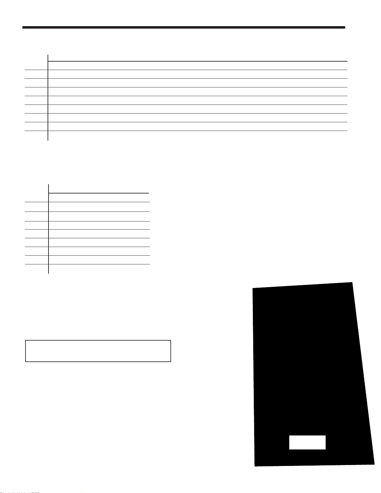
1.C Model Identication
Consult the Rating Plate on the side of the unit. The
following information describes the model nomenclature
(number structure).
(1-2) Model Series Designation
N T = NeoTherm
(3) Usage
H = Hydronic
V = Volume Water
(4-6) Size
1 5 0 = 150,000 BTU/hr input
1 9 9 = 199,000 BTU/hr input, Heater only
2 1 0 = 210,000 BTU/hr input, Boiler only
2 8 5 = 285,000 BTU/hr input
3 9 9 = 399,000 BTU/hr input
5 0 0 = 500,000 BTU/hr input
6 0 0 = 600,000 BTU/hr input
7 5 0 = 750,000 BTU/hr input
8 5 0 = 850,000 BTU/hr input
(7) Fuel
N = Natural Gas
P = LP Gas
(8) Options Code
X = Standard Unit
J = CSD-1, FM, GAP, IL Code (size 500-850 only)
C - STANDARD (Canada)
D - CSD-1 (Canada)
E - OUTDOOR
F - OUTDOOR (Canada)
G - CSD-1, OUTDOOR
H - CSD-1, OUTDOOR (Canada)
(9) Pump Options
N = Pump included (150-500 only)
X = No pump (conguration available for all sizes)
W = HLW w/ Pump (option for Heater only)
L = HLW w/out Pump (option for Heater only)
(10) Revision
3 = Third version
Model Nomenclature
1 2 3 4 5 6 7 8 9 10 11
SERIES
N T
USAGE
H -
HYDRONIC
V - VOLUME
WATER
SIZE
MBTU/h
1 5 0
1 9 9
2 1 0
2 8 5
3 9 9
5 0 0
6 0 0
7 5 0
8 5 0
FUEL
N - NATURAL
P - PROPANE
OPTIONS CODE
X -
STANDARD
J - CSD-1, FM, GAP ,
IL (500-850 only)
C - ST ANDARD (Canada)
D - CSD-1 (Canada)
E - OUTDOOR
F - OUTDOOR (Canada)
G - CSD-1, OUTDOOR
H - CSD-1, OUTDOOR
(Canada)
PUMP OPTIONS
N -
PUMP INCL.
(150-500 only)
X -
NO PUMP
W - HLW w/PUMP
(opt for Heater only)
L - HLW w/out
PUMP
(opt for Heater only)
3 N T
REVISION
3 - THIRD
Page 6
Page 2
1.D Safety Notes
LAARS Heating Systems
WARNING
These units must be installed in accordance with
the procedures detailed in this manual, or the
Manufacturer’s warranty will be voided. The installation
must conform to the requirements of the local jurisdiction
having authority , and, in the United States, to the latest
edition of the National Fuel Gas Code, ANSI Z223.1/
NFPA54. In Canada, the installation must conform
to the latest edition of CSA B149.1 Natural Gas and
Propane Gas Installation Code, and/or local codes.
Where required by the authority having jurisdiction, the
installation of these units must conform to the Standard
for Controls and Safety Devices for Automatically Fired
Boilers, ANSI/ASME CSD-1. Any modications to the
boiler, its gas controls, or wiring may void the warranty. If
eld conditions require modications, consult the factory
representative before initiating such modications.
NOTE: All installations must be made in accordance with
1) American National Standard Z223.1/NFPA54-Latest
Edition “National Fuel Gas Code” or
2) CSA B149.1 “Natural Gas and Propane Installation
Code” or in Canada reference the B149.1 latest
edition and with the requirement of the local utility or
other authorities having jurisdiction. Such applicable
requirements take precedence over the general
instructions contained herein. All electrical wiring is to
be done in accordance with the local codes, or in the
absence of local codes, with: 1) The National Electrical
Code ANSI/NFPA No. 70-latest Edition, or
2) CSA STD. C22.1 “Canadian Electrical Code - Part
1”. This appliance must be electrically grounded in
accordance with these codes.
DANGER
• Water temperature over 125°F (52°C) can cause
severe burns instantly or death from scalds.
• Children, disabled and
elderly are at highest
risk of being scalded.
• See instruction manual
before setting temperature
at heating appliance.
• Feel water before bathing
or showering.
• If this appliance is used
to produce water that could scald if too hot, such
as domestic hot water use, adjust the outlet control
(limit) or use temperature limiting valves to obtain a
maximum water temperature of 125°F (52°C).
WARNING
Fire or Explosion Hazard
Improper conguration can cause fuel buildup and
explosion. Improper user operation may result in
property loss, severe physical injury, or death.
Any changes to safety-related conguration
parameters must only be done by experienced and/or
licensed burner/boiler operators and mechanics.
If any odor of gas is detected, or if the gas burner does
not appear to be functioning in a normal manner, close
the main gas shuto valve. Do not shut o the power
switch. Contact your heating contractor, gas company,
or factory representative.
DANGER
The inlet gas pressure to the appliance must not
exceed 13” W.C. (3.2kPa).
WARNING
:
Cancer and Reproductive Harm
www.P65Warnings.ca.gov
As required by the State of California Proposition 65.
Note: The unit is protected against over-pressurization.
A pressure relief valve is included with each unit.
WARNING
Carbon Monoxide Hazard
Improper adjustment of the burners may lead to poor
combustion quality , increasing the amount of carbon
monoxide produced. Excessive carbon monoxide levels
may lead to personal injury or death.
Page 7
NEOT
Electrical Shock Hazard
Edition, or 2) CSA STD. C22.1 “Canadian Electrical Code
HERM
Electrical shock can cause severe injury, death or
property damage. Disconnect the power supply before
beginning installation or changing the wiring to prevent
electrical shock or damage to the equipment. It may
be necessary to turn o more than one power supply
All electrical wiring is to be done in accordance with
local codes, or in the absence of local codes, with: 1)
The National Electrical Code ANSI/NFPA No. 70 - latest
- Part 1.” This appliance must be electrically grounded in
Commercial Boilers and Water Heaters, 150 to 850 MBTU/h
WARNING
disconnect.
accordance with these codes.
Page 3
Page 8
Page 4
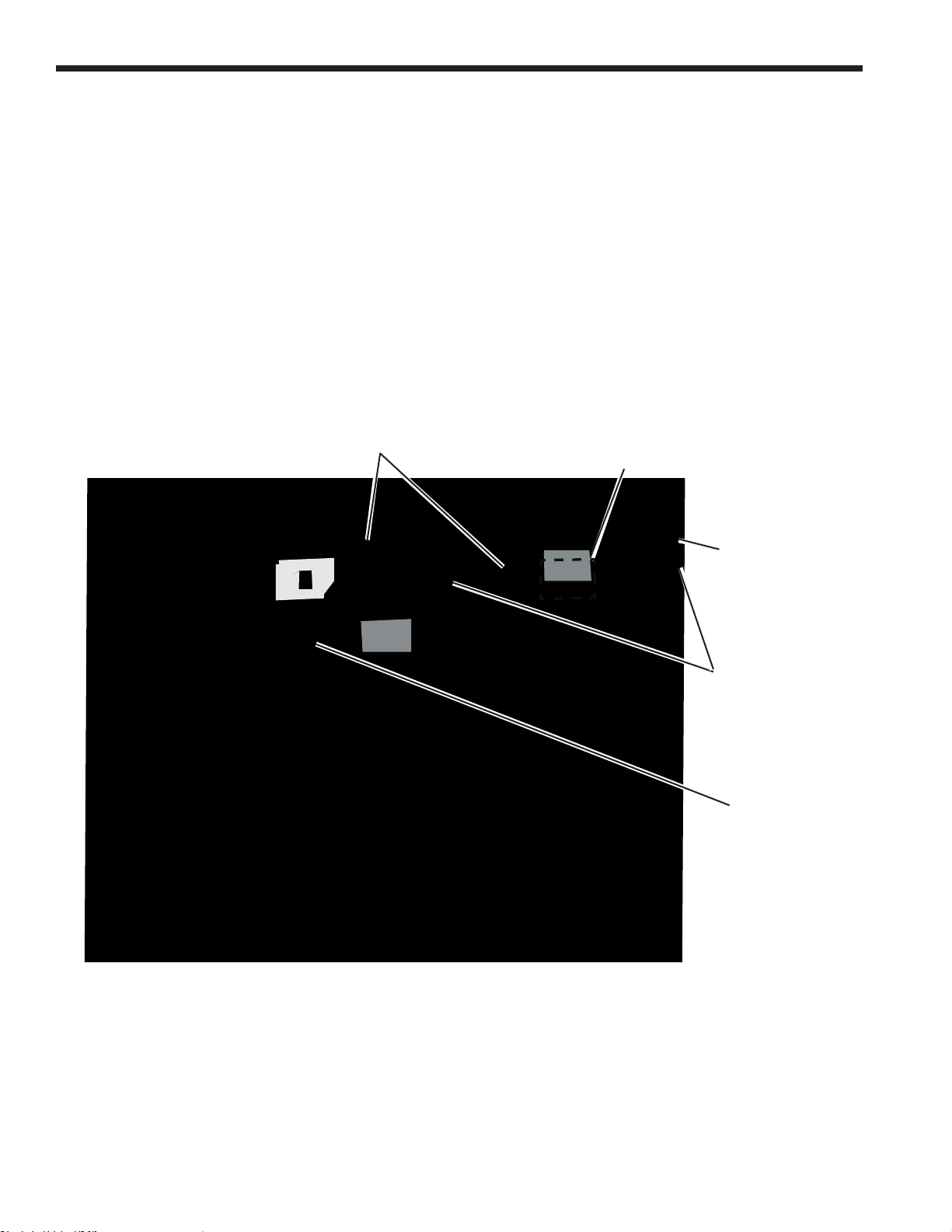
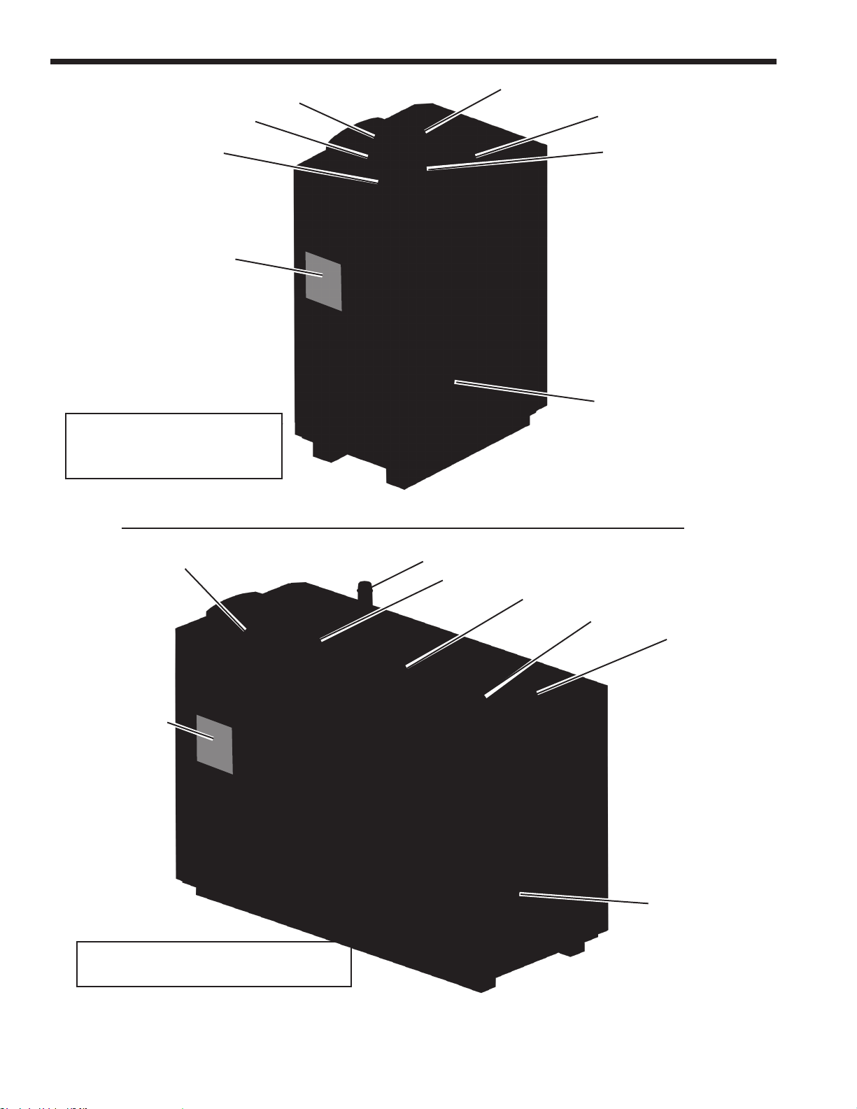
1.E Model Overview
LAARS Heating Systems
These units are oered in both Indoor and Outdoor
models for all sizes. The physical appearance of the
indoor and outdoor units is drastically dierent because
the outdoor model oers a fully weathertight enclosure
that hides the touchscreen. Whereas the indoor model
is not fully weathertight and the touchscreen can be
accessed without having to open the unit. See Figure 1
through Figure 9.
Both the indoor and the outdoor models have the
On/O switch on the outside of the unit.
ON / OFF
SWITCH
Both also have the Rating Plate on the outside panel
to the right. See Figure 8 on page 8
The only component (interior) dierence between the
indoor and outdoor models is that all of the piping for the
outdoor model, with the exception of the exhaust vent, is
at the BACK of the unit. Figure 9 on page 9
The gas connection, the air inlet, and the water inlet and
outlet are all at the back of the unit. This is consistent for
all sizes.
THE TOUCH SCREEN ON
OUTDOOR UNIT IS LOCATED
BEHIND FRONT PANEL
2 SCREWS
FASTEN FRONT
PANEL INTO
PLACE
INDOOR OUTDOOR
Figure 1. All models open from the front
DOOR LATCHES
(RELEASE BOTH
LA TCHES T O
OPEN)
DOOR
HANDLE
(PULL TO OPEN)
Page 9
NEOT
HERM
Commercial Boilers and Water Heaters, 150 to 850 MBTU/h
Page 5
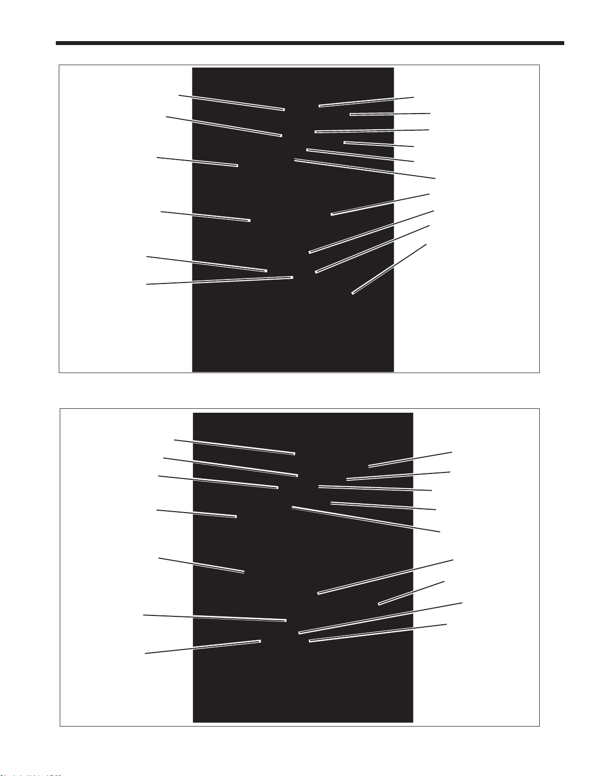
EXHAUST VENT CONNECTION
GAS CONNECTION
TOUCHSCREEN
HEAT EXCHANGER
AIR/ GAS
BLOWER
VENTURI
PRESSURE RELIEF VALVE
WATER INLET
WATER OUTLET
AIR INLET CONNECTION
AIR PRESSURE SWITCH
ON / OFF SWITCH
DRAIN VALVE
GAS VALVE
AIR TRANSITION
CONDENSATE TRAP
Figure 2. Location of Components, Sizes 150-210
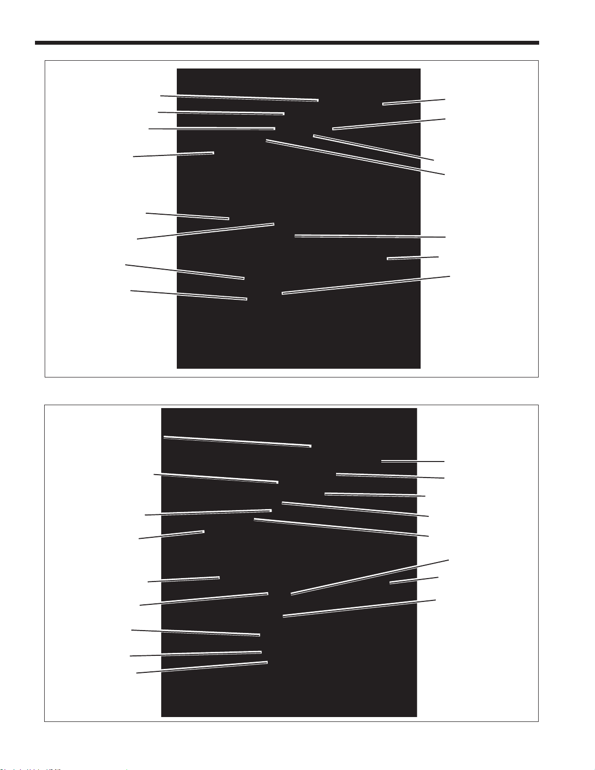
EXHAUST VENT CONNECTION
AIR INLET CONNECTION
GAS CONNECTION
TOUCHSCREEN
HEAT EXCHANGER
GAS VALVE
AIR/ GAS
BLOWER
WATER INLET
WATER OUTLET
PRESSURE RELIEF VALVE
AIR PRESSURE SWITCH
ON / OFF SWITCH
DRAIN VALVE
CONDENSATE TRAP
VENTURI
AIR TRANSITION
Figure 3. Location of Components, Size 285
Page 10
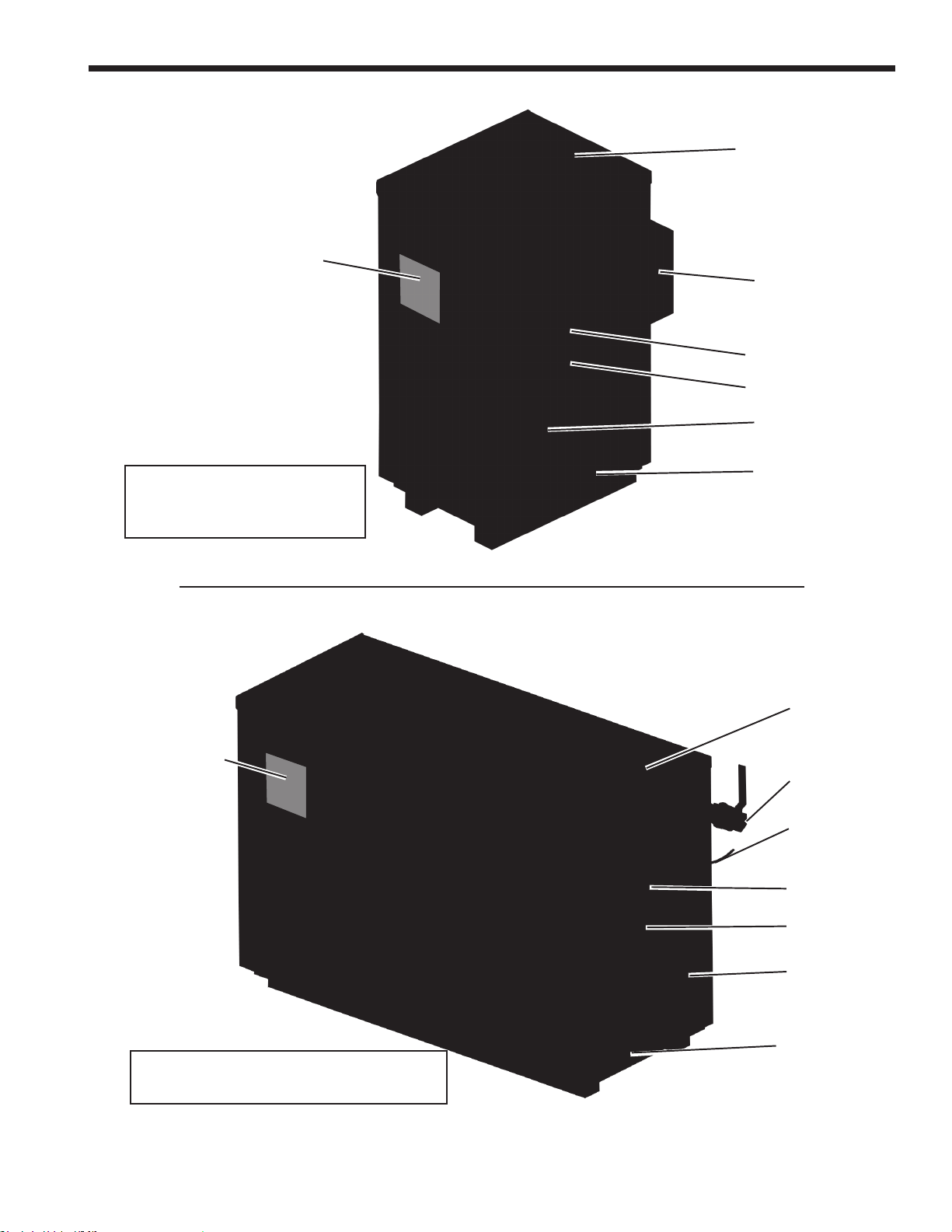
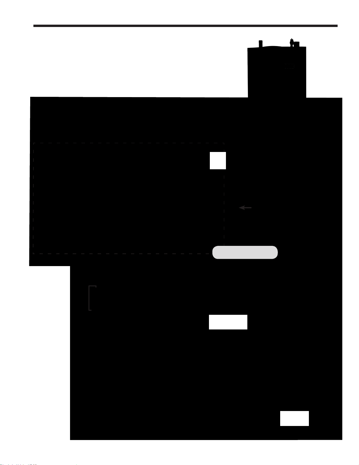
Page 6
LAARS Heating Systems
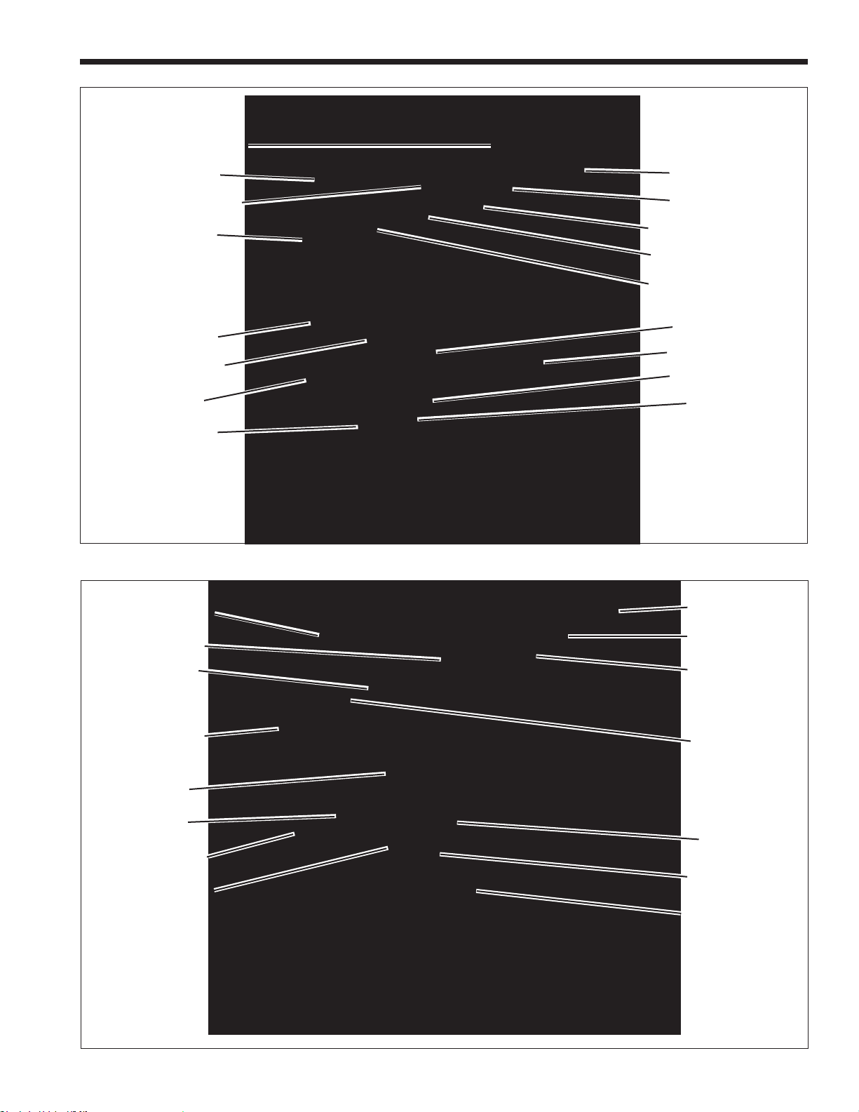
EXHAUST VENT CONNECTION
PRESSURE RELIEF VALVE
GAS CONNECTION
TOUCHSCREEN
HEAT EXCHANGER
MANUAL SHUTOFF
GAS VALVE
AIR/ GAS
BLOWER
VENTURI
WATER INLET
WATER OUTLET
AIR INLET CONNECTION
ON / OFF SWITCH
DRAIN VALVE
CONDENSATE TRAP
GAS VALVE
Figure 4. Location of Components, Indoor Size 399
EXHAUST VENT CONNECTION
PRESSURE RELIEF VALVE
GAS CONNECTION
TOUCHSCREEN
HEAT EXCHANGER
MANUAL SHUTOFF
GAS VALVE
VENTURI
GAS VALVE
GAS PRESSURE
SWITCH
WATER INLET
WATER OUTLET
AIR INLET CONNECTION
AIR PRESSURE SWITCH
ON / OFF SWITCH
DRAIN VALVE
CONDENSATE TRAP
AIR/ GAS BLOWER
Figure 5. Location of Components, Indoor Size 500
Page 11
NEOT
HERM
EXHAUST VENT CONNECTION
Commercial Boilers and Water Heaters, 150 to 850 MBTU/h
Page 7
GAS CONNECTION
PRESSURE RELIEF VALVE
TOUCHSCREEN
MANUAL SHUTOFF
GAS VALVE
HEAT EXCHANGER
GAS VALVE
MANUAL SHUTOFF
GAS VALVE
Figure 6. Location of Components, Size 600
WATER INLET
WATER OUTLET
AIR INLET CONNECTION
AIR PRESSURE SWITCH
ON / OFF SWITCH
DRAIN VALVE
CONDENSATE TRAP
AIR/ GAS BLOWER
VENTURI
GAS CONNECTION
PRESSURE RELIEF
VALVE
AIR INLET
TOUCHSCREEN
GAS VALVE
VENTURI
AIR/ GAS BLOWER
HEAT EXCHANGER
WATER INLET
EXHAUST VENT
CONNECTION
WATER OUTLET
ON / OFF SWITCH
DRAIN VALVE
MANUAL SHUTOFF
GAS VALVE
CONDENSATE TRAP
Figure 7. Location of Components, Sizes 750 and 850
Page 12
Page 8
LAARS Heating Systems
CONNECTION
WATER OUTLET
AIR INLET
RATING PLATE
Indoor 150 MBH
For piping dimensions/
locations for all Indoor units,
See Table 1 on page 10
GAS
PRV
EXHAUST
VENT
W
ATER INLET
CONDENSATE
TRAP OUTLET
(Trap is built-in)
AIR INLET
RATING PLATE
Indoor 850 MBH
For piping dimensiona/locations for all
Indoor units, See Table 1 on page 10
GAS CONNECTION
PRV
WATER OUTLET
W
ATER INLET
EXHAUST
VENT
CONDENSATE
TRAP OUTLET
(Trap is built-in)
GAS
CONNECTION
Figure 8. Connection piping is on the BACK for ALL Outdoor Sizes
Page 13
NEOT
HERM
Commercial Boilers and Water Heaters, 150 to 850 MBTU/h
EXHAUST
VENT
RATING PLATE
AIR INLET
FILTER BOX
Page 9
Outdoor 150 MBH
For piping dimensions/
locations for all outdoor units,
See Table 2 on page 12
RATING PLATE
WATER OUTLET
WATER INLET
CONDENSA
TRAP OUTLET
(Trap is built-in)
CONNECTION
PRV must be added to this pipe
*
during installation.
TE
GAS
EXHAUST
VENT
GAS
CONNECTION
*
Outdoor 850 MBH
For piping dimensions/locations for all
Outdoor units, See Table 2 on page 12
Figure 9. Connection piping is on the BACK for ALL Outdoor Sizes
POWER SUPPLY
FOR PUMP
(if ordered with
WATER OUTLET
W
ATER INLET
AIR INLET
FILTER BOX
CONDENSATE
TRAP OUTLET
(Trap is built-in)
PRV must be added to this pipe
*
during installation.
a pump)
*
Page 14
Page 10
L
SUGGESTED SERVICE CLEARANCE
38
1
/
2
(98)
8
3
/
4
(22)
7
1
/
2
(19)
25 (64)
LAARS Heating Systems
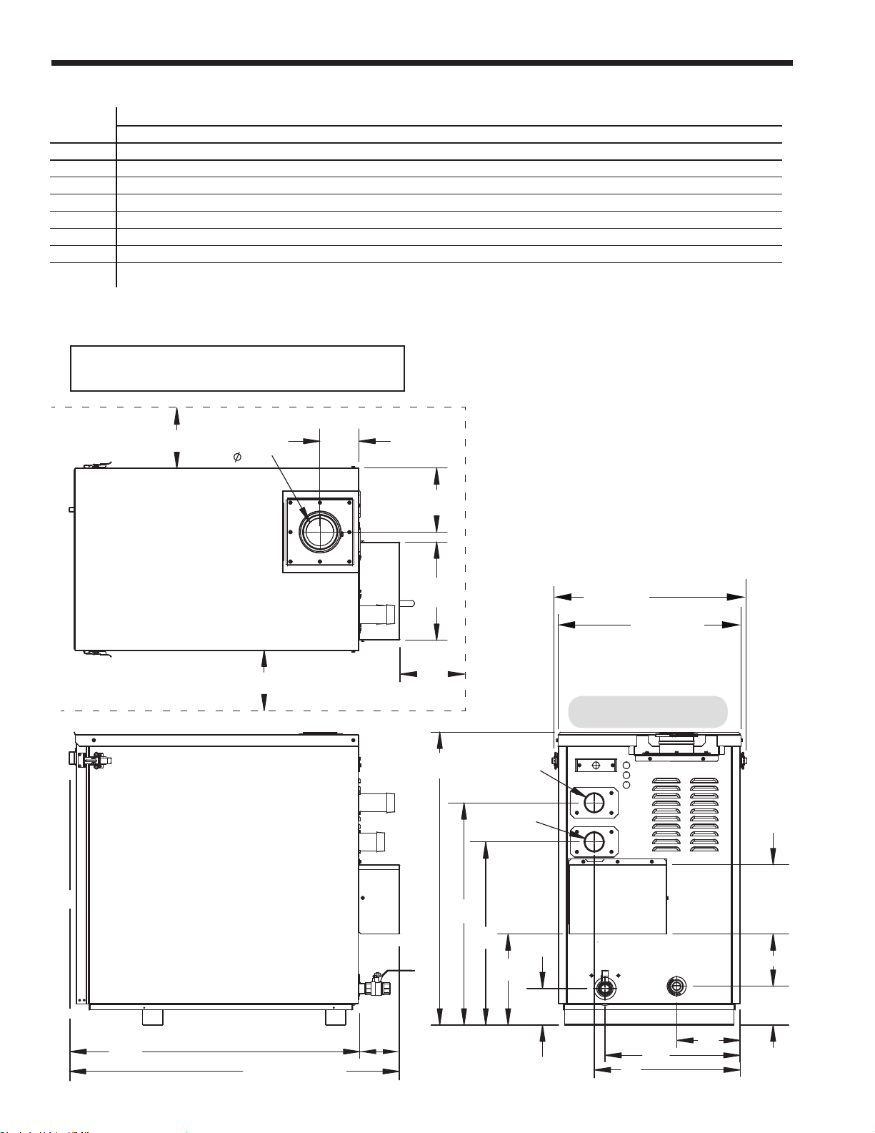
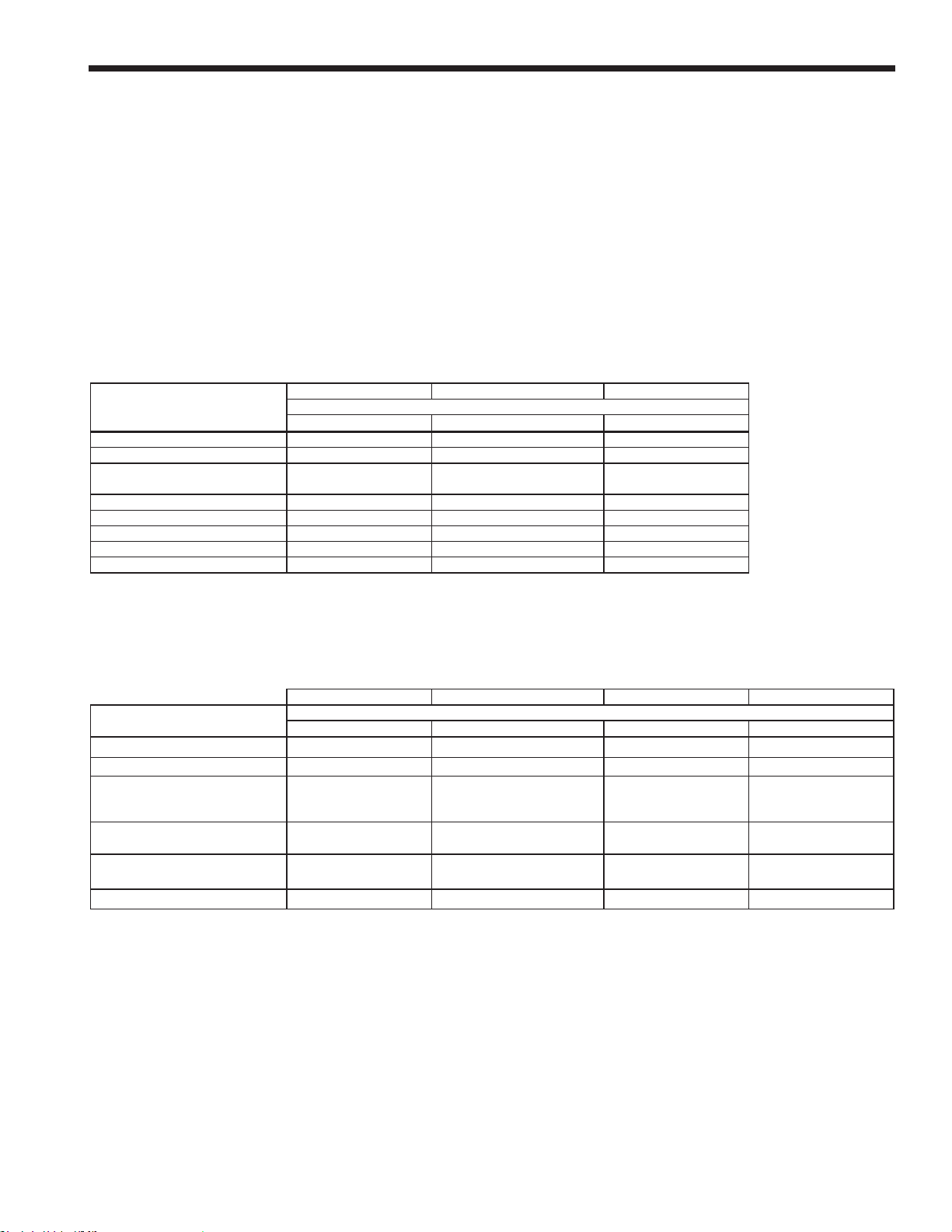
1.F Dimensions, Indoor Models
A B C D E F G J K M N
Size in cm in cm in cm in cm in cm in cm in cm in cm in cm in cm in cm
150 13¼ 34 5¼ 14 18¼ 46 3¼ 8 10¾ 28 7½ 19 14¼ 36 19½ 49 7½ 19 15¼ 39 13 33
199/210 20½ 52 5¼ 14 18¼ 46 3¼ 8 17¾ 45 7½ 19 14¼ 36 19½ 49 11¾ 30 15¼ 39 13 33
285 20¼ 52 7¼ 19 19½ 50 6¼ 16 11¼ 29 13½ 34 14 36 15 38 17 43 18¾ 48 13 33
399 25 64 5¼ 13 19½ 50 4¼ 11 14¾ 37 18½ 47 19¼ 49 16½ 42 21¾ 55 18¾ 48 13 33
500 30¼ 77 5¼ 13 19½ 50 4¼ 11 15¼ 38 20 51 20½ 52 19 48 26 66 18¾ 48 13 33
600 29¾ 76 5 13 19½ 50 4¼ 11 15 38 20 51 3 8 19 48 26 66 18¾ 48 8¼ 21
750 35½ 90 6 15 19½ 50 5¼ 13 19 48 40½ 103 3¼ 8 19 48 30¾ 78 18¾ 48 8¼ 21
850 39¾ 101 6 15 19½ 50 5¼ 13 19 48 44¾ 114 3½ 9 19 48 35 89 18¾ 48 8¼ 21
Table 1. Dimension Drawing, Indoor Sizes 150-850
SIZE in cm in cm in cm
L
AIR INLET VENT
(length)
150 19½ 49 3 7.6 3 7.6
199/210
285 26¾ 68 4 11 4 11
399 31½ 80 4 11 4 11
500 37¾ 96 4 11 4 11
600 37¾ 96 4 11 4 11
750 51 130 4 11 6 17
850 55¼ 140 4 11 6 17
26¾ 68 3 7.6
3 7.6
Table 1. (dimensions continued)
Dimensions are nominal and are shown
in inches, cm.
*Unit is shipped with adapters for the air
and vent that accept standard pipe of
the proper size and type.
For Water Connection Pipe Sizes, See “Table 14.
Water Connection Pipe Sizes” on page 28
Page 15
NEOT
L
SUGGESTED SERVICE CLEARANCE
38
1
/
2
(98)
8
3
/
4
(22)
7
1
/
2
(19)
HERM
Commercial Boilers and Water Heaters, 150 to 850 MBTU/h
All Indoor Units have a very
similiar component design with
piping dimensions/locations
that increase as the unit size
increases.
Water and gas piping is
always on the left side of the
unit. Table 1 gives the exact
dimensions for all of the
dierent model sizes.
Page 11
See “Table 3. Suggested
Service Clearances” on
page 16
ALL Models
Page 16
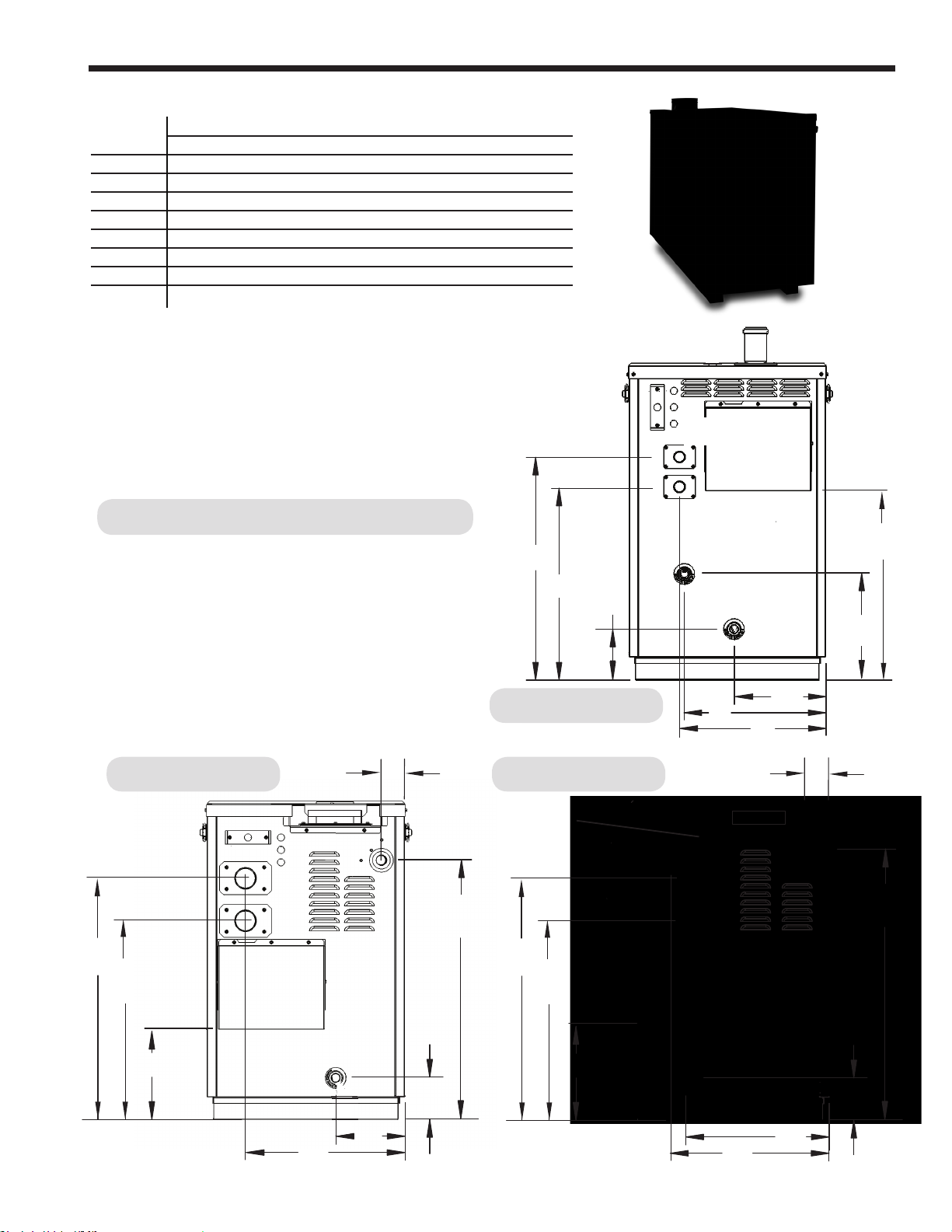
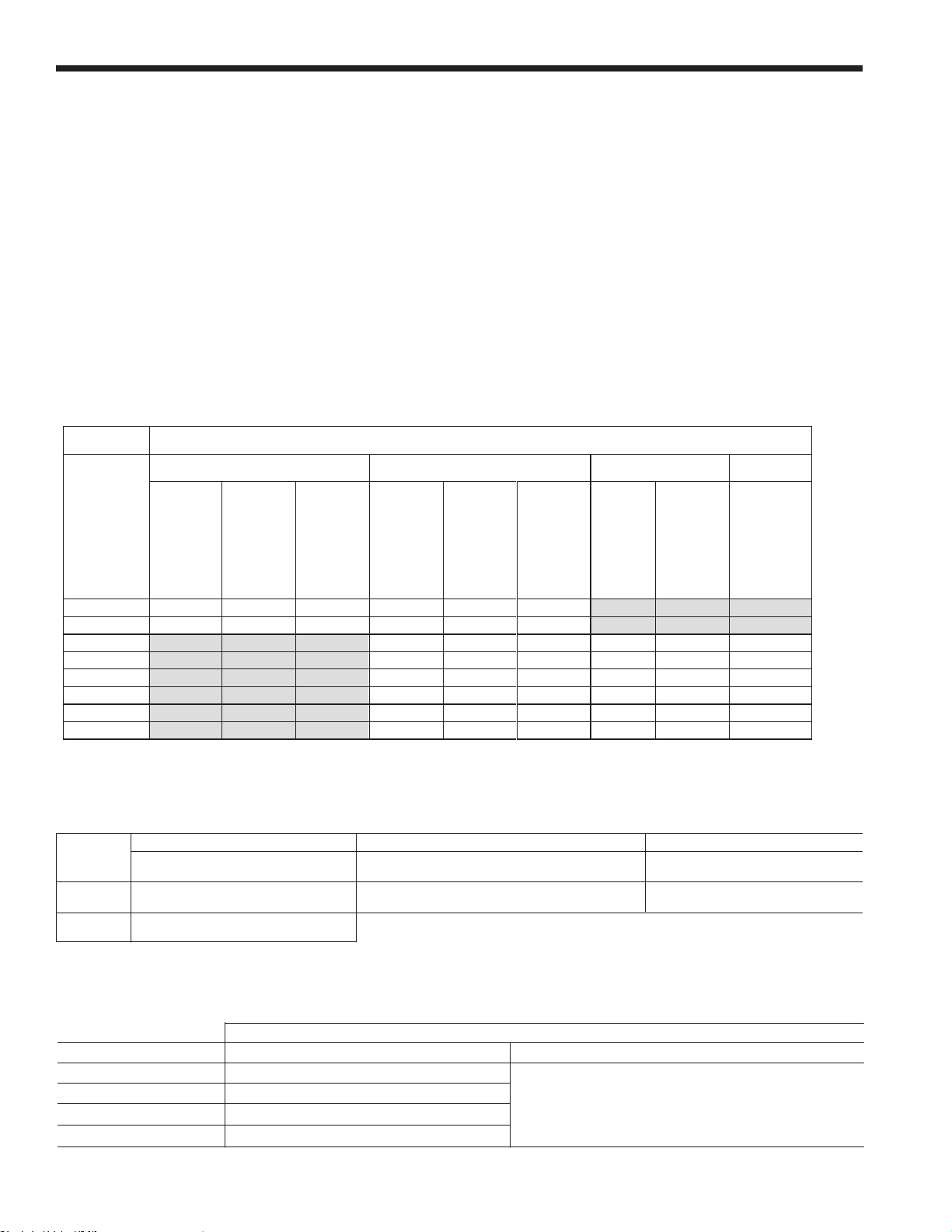
Page 12
SIZE
in cm in cm in cm in cm in cm in cm in cm in cm in cm in cm in cm in cm
150
6-1/4" 16 11" 28 13" 33 17-1/4" 43.8 23-1/2" 60 18" 45.7 27" 69 23-1/2" 60 5-1/4" 13 20" 60 25-1/2" 65 3 7.6
199 / 210
6-1/4" 16 11" 28 13" 33 17-1/4" 43.8 23-1/2" 60 18" 45.7 27" 69 24-1/2" 60 5-1/4" 13 27" 68.6 32-1/2" 82.5 3 7.6
285
6" 15.5 11" 28 5" 13 17-1/4" 43.8 24" 61 19" 48 28-1/4" 72 12" 30.5 7-1/4" 18.4 27" 68.6 32-1/2" 82.5 4 11
399
8" 15.5 19-1/2" 50 7-3/4" 20 17-1/4" 43.8 24" 61 19" 48 28-1/4" 72 12" 30.5 6" 15.2 31-1/4"" 80.5 37-3/4" 96 4 11
500
5" 13 17-3/4" 45 5" 13 8-1/4" 21
24" 61 19" 48 29-1/4" 74 12" 30.5 5.5" 14 38" 96.5 43-1/2" 110.5 4 11
600
33-1/2" 85 3.0" 8 5" 13 8-1/4" 21 24" 61 19" 48 29-1/4" 74 12" 30.5 5-3/4" 14.6 38" 96.5 43-1/2" 110.5 4 11
750
32-3/4" 83.2 3.0" 8 5-1/4" 13.4 17-1/4" 43.8 24" 61 19" 48 29-1/4" 74 12" 30.5 5-3/4" 14.6 51-1/4" 130 57-3/4" 146.7 6 17
850
32-3/4"
83.2
3.0"
8
5-1/4"
13.4
17-1/4"
43.8
24"
61
19"
48
29-1/4"
74
12"
30.5
5-3/4"
14.6
55-3/4" 141.5 61-1/4" 155.5 6 17
E
F
VENT
ABCDGJK
L (Length)
T (Total Length)
1.G Dimensions, Outdoor Models
Table 2. Dimension Drawing, OUTDOOR Sizes 150-850
LAARS Heating Systems
For Water Connection Pipe Sizes, See “Table 14.
Water Connection Pipe Sizes” on page 28
12 (31)
VENT
K
TOP VIEW
12 (31)
SUGGESTED SERVICE CLEARANCE
See “Table 3. Suggested Service Clearances” on page 16
8 (21)
(33)
13
12
(31)
1
38
/
(98)
2
Dimensions are nominal and are shown
in inches, cm.
*Unit is shipped with adapters for the air
and vent that accept standard pipe of
the proper size and type.
26 (66)
25 (64)
ALL Model Sizes
285 - 500 MBH
WATER
OUTLET
WATER
INLET
G
AIR FILTER
BOX
9 (23)
E
J
GAS INLET
A
L
Total length
T
1
/
5
(9)
2
F
RIGHT SIDE VIEW
CONDENSATE
TRAP OUTLET
D
B
BACK VIEW
C
Page 17
NEOT
F
8
21
13
33
8
21
13
33
SIZE
in cm in cm in cm in cm in cm in cm in cm in cm in cm in cm in cm in cm
150
6-1/4" 16 11" 28 13" 33 17-1/4" 43.8 23-1/2" 60 18" 45.7 27" 69 23-1/2" 60 5-1/4" 13 20" 60 25-1/2" 65 3 7.6
199 / 210
6-1/4" 16 11" 28 13" 33 17-1/4" 43.8 23-1/2" 60 18" 45.7 27" 69 24-1/2" 60 5-1/4" 13 27" 68.6 32-1/2" 82.5 3 7.6
285
6" 15.5 11" 28 5" 13 17-1/4" 43.8 24" 61 19" 48 28-1/4" 72 12" 30.5 7-1/4" 18.4 27" 68.6 32-1/2" 82.5 4 11
399
8" 15.5 19-1/2" 50 7-3/4" 20 17-1/4" 43.8 24" 61 19" 48 28-1/4" 72 12" 30.5 6" 15.2 31-1/4"" 80.5 37-3/4" 96 4 11
500
5" 13 17-3/4" 45 5" 13 8-1/4" 21
24" 61 19" 48 29-1/4" 74 12" 30.5 5.5" 14 38" 96.5 43-1/2" 110.5 4 11
600
33-1/2" 85 3.0" 8 5" 13 8-1/4" 21 24" 61 19" 48 29-1/4" 74 12" 30.5 5-3/4" 14.6 38" 96.5 43-1/2" 110.5 4 11
750
32-3/4" 83.2 3.0" 8 5-1/4" 13.4 17-1/4" 43.8 24" 61 19" 48 29-1/4" 74 12" 30.5 5-3/4" 14.6 51-1/4" 130 57-3/4" 146.7 6 17
850
32-3/4"
83.2
3.0"
8
5-1/4"
13.4
17-1/4"
43.8
24"
61
19"
48
29-1/4"
74
12"
30.5
5-3/4"
14.6
55-3/4" 141.5 61-1/4" 155.5 6 17
E
F
VENT
A
BCDGJ
K
L (Length)
T (Total Length)
5-3/4"
14.6
55-3/4" 141.5 61-1/4" 155.5 6 17
VENT
K
L (Length)
T (Total Length)
HERM
Commercial Boilers and Water Heaters, 150 to 850 MBTU/h
Table 2. (dimensions ontinued)
Page 13
Ø
WATER
OUTLET
AIR FILTER
BOX
BACK VIEWS of the Outdoor Models
The Outdoor versions have a greater component location
variance than the Indoor models. 4 Back Views are given to
show the piping dimensions/locations for all of the dierent
piping layouts. Table 2 gives the exact dimensions for all of the
dierent model sizes.
600 MBH
WATER
OUTLET
WATER
INLET
B
GAS INLET
A
G
E
A
150 - 210 MBH
750 - 850 MBH
KNOCK-OUTS FOR
POWER TO
ALL OPTIONAL
EQUIPMENT
WATER
INLET
CONDENSATE
TRAP OUTLET
GAS INLET
D
B
GAS INLET
WATER
OUTLET
WATER
INLET
J
C
B
A
G
AIR FILTER
BOX
CONDENSATE
TRAP OUTLET
F
D
C
E
J
G
E
J
AIR FILTER
BOX
CONDENSATE
TRAP OUTLET
C
D
F
Page 18
Page 14
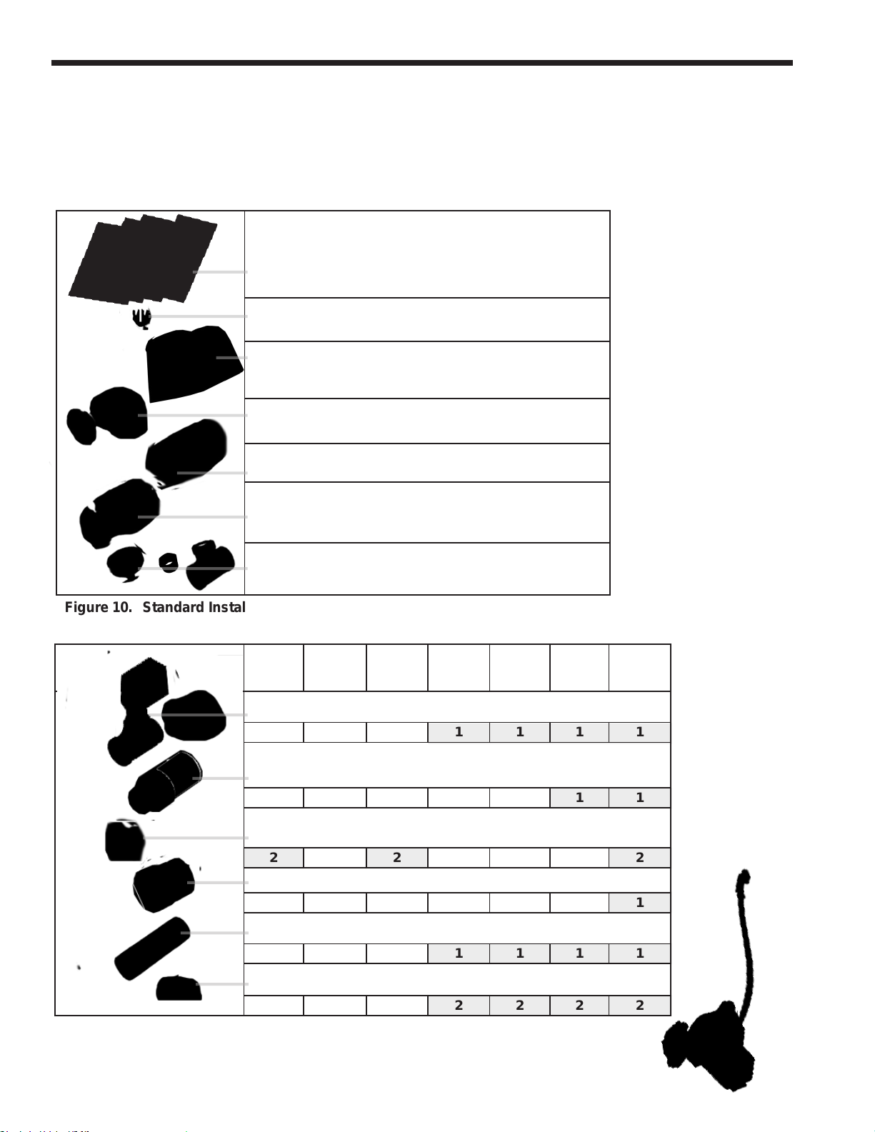
1.H The Installation Kit (installation parts box).
The Indoor models are shipped in a single crate with the
Installation Kit (cardboard box). Check the contents of the
Installation Kit with the items listed in Figure 10 and Figure 11.
Additional parts may be packed inside the unit.
Doc ument Bag
(all documents in one bag)
Term inal Block Jumper
(the Terminal Block Jumper is in the document bag)
Sen sor Kits (Tank, Outdoor and System Sensors, all in the
same bag (2 boxes, a sensor, and a wire).
Volume Water Heaters will not have an Outdoor Sensor
Air I ntake Terminal Assembly
(elbow and a screen)
Vent Pipe
Exh aust Terminal Assembly
(end pipe and a screen),
Tem p/Pressure Gauge Kit
(a bushing, an NPT Tee, and the gauge in a small box)
Figure 10. Standard Installation Components
LAARS Heating Systems
Some accessory
items may be shipped
in separate packages.
Verify receipt of all
packages listed on
the packing slip.
Inspect everything for
damage immediately
upon delivery, and
advise the carrier
of any shortages or
damage. Any such
claims should be led
with the carrier.
The carrier, not the
shipper, is responsible
for shortages and
damage to the
shipment whether
visible or concealed.
80/105
Flow Switch Kit
150
199/210
285 399 500 600 7
(ow switch, 2 wires, and an NPT tee)
1 1 1 1
Exhaust Adapter Assembly
Grid Screen, Venting
2 2 2
Vent Adapter, 6” PVC to 6” Stainless Steel
NPT Pipe (for ow switch)
1 1 1 1
Grommets for ow switch wires
2 2 2 2
Figure 11. Additional Components, depending on model size.
50/850
1 1
1
Optional Indoor Pump Kit
Page 19
NEOT
EXPLODED VIEW
4
3
2
HARNESS
D
C
2
DWG NO.
50D4140
SH
1
REV
A
CJ 5/17/16
REVISIONS
REV.
CHANGE:
APPR
ENGR APPR
ECN
DRAFT
CHECK
REMOVED ITEM 2 A2116100 FROM 50D4140.
A
15-127N-05
XR 5/17/16
AIR FILTER
OUTLET
WATER
WATER
INLET
BOX
GAS INLET
CONDENSATE
TRAP OUTLET
J
A
C
G
E
VENT
K
8
(21)
13
(33)
9 (23)
38
1
/
2
(98)
TOP VIEW
SUGGESTED SERVICE CLEARANCE
12 (31)
12
(31)
12
(31)
HERM
Commercial Boilers and Water Heaters, 150 to 850 MBTU/h
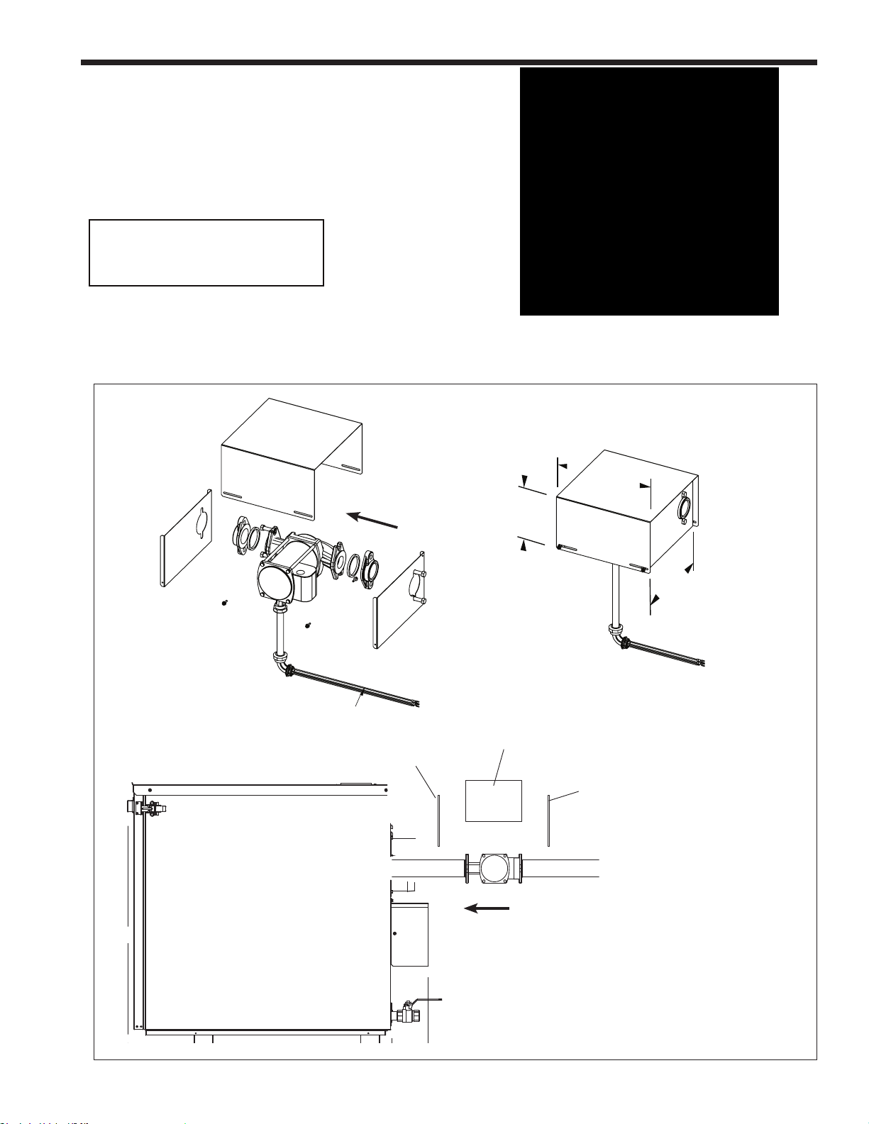
The OUTDOOR Model Installation Kits, in
addition to what is shown in Figure 10 and
Figure 11, will include:
Some Class IV venting
components are not included with
units shipped to Canada.
Outdoor Pump Kit
Page 15
Vent Pipe Extender,
Pipe Adapter,
Bird Screen,
PRV,
NPT Pipe Tee
Figure 12. Additional components for
outdoor models.
EXPLODED VIEW
HARNESS
FLOW
SIDE PANEL
11
1/
4
6
1/
”
2
ASSEMBLED
VIEW
TOP PANEL
FLOW
SIDE PANEL
WATER INLET
”
11
1/
”
4
Figure 13. Outdoor Pump Kit
NOTE: The pump and outdoor housing will
typically be shipped inside the unit. Pump will
need to be piped and wired on site. A 62” long
wire harness is provided but a conduit will need
to be provided by the electrician at time of boiler
installation.
Page 20

Page 16
LAARS Heating Systems
SECTION 2
LOCATING THE UNIT
2.A General Information
The ‘Indoor’ unit is designed and CSA-certied
for indoor installations only.
The ‘Outdoor’ unit is designed and CSA-certied for
outdoor installations only.
If installing in a location that may experience freezing
temperatures, precautions must be taken to prevent water
in the heat exchanger and condensate inside and outside
of the boiler from freezing. Damage due to freezing water
or condensate is not covered by the warranty.
The appliance should be located to provide clearances on
all sides for maintenance and inspection. It should not be
located in an area where leakage of any connections will
result in damage to the area adjacent to the appliance or
to lower oors of the structure. When such a location is
not available, it is recommended that a suitable drain pan,
adequately drained, be installed under the appliance.
Always install the unit on a rm, level surface.
The unit is design certied by CSA-International for
installation on combustible ooring; in basements; in
closets, utility rooms or alcoves. These units must never be
installed on carpeting. The location for the unit should be
chosen with regard to the vent pipe lengths and external
plumbing and on a level surface.
The Indoor units shall be installed such that the gas ignition
system components are protected from water (dripping,
spraying, rain, etc.) during operation and service (circulator
replacement, control replacement, etc.). When vented
vertically, the unit must be located as close as practical to
the vertical section of the vent. If the vent terminal and/or
combustion air terminal terminate through a wall, and there
is potential for snow accumulation in the local area, both
terminals should be installed at an appropriate level above
grade or the maximum expected snow line.
The Outdoor units must be installed at least 10 ft (the vent
pipe) from any door or window. The exhaust vent shall
not be under any overhang or roof. Use only the vent
components included with the boiler.
The dimensions and requirements that are shown in Table
3 should be met when choosing the locations for the
appliance.
2.B Locating Appliance for Correct Vent
Distance from Outside Wall or
Roof Termination
The forced draft combustion air blower in the appliance
has sucient power to vent properly when the
guidelines in Table 4 are followed.
For concentric vent terminal kit (optional), follow
installation instructions included with the kit.
NOTE: When located on the same wall, the
combustion air intake terminal must be installed a
minimum of 12” below the exhaust terminal.
Models 399-850 also require a minimum horizontal
distance from intake to exhaust terminal of 36”.
INDOOR OUTDOOR
UNIT SURFACE INCHES CM INCHES CM
Left Side 1 2.5 12 31
Right Side 12 31 12 31
Top (for ue) 24 61 48 122
Back 6 15 12* 31
Closet, Front 1 2.5 1 2.5
Front 24 61 24 61
Vent Per Vent Manufacturer
Certied by CSA for zero clearance to combustible materials on all sides.
from lter box face. See “Table 2. Dimension Drawing, OUTDOOR
*
Sizes 150-850” on page 12
*
Table 3. Suggested Service Clearances
INTAKE / EXHAUST
STANDARD MAX EQUIV. OPTIONAL MAX EQUIV.
SIZE VENT FT. M VENT FT. M
150 3” 100 30 n/a — —
199/210 3” 100 30 n/a — —
285 4” 100 30 n/a — —
399 4” 100 30 n/a — —
500 4” 100 30 n/a — —
600
750 4” 40 6.1 6” 100 30
850 4” 40 6.1 6” 100 30
Combustion Intake and Vent must be the same size.
Installations in the U.S. require exhaust vent pipe that is a combination
of PVC & CPVC complying with ANSI/ASTM D1785 F441 or stainless
steel complying with the stainless steel vent suppliers listed in Section 3.
Installations in Canada require exhaust vent pipe that is certied to
ULC S636.
Intake (air) pipe must be PVC or CPVC that complies with ANSI/ASTM D1785
F441, ABS that complies with ANSI/ASTM D1527 or galvanized material.
The installer must comply fully with the manufacturer’s installation
instructions, including use of minimum exhaust length CPVC, to main-
tain ANSI Z21.13 safety certication.
Closet and alcove installations do not allow the use of PVC under any
circumstances
To calculate max equivalent length, measure the linear feet of the pipe,
and add 5 feet (1.5m) for each 90° elbow used. Add 2 1/2 feet (.76
meters) for each 45 elbow used.
*
feet, any even or uneven combination of length is allowed. For overall
lengths greater than 40 equivalent feet, the exhaust may be up to 20
feet greater than the intake length.
4” 40 6.1 6” 100 30
*
For any combination of vent and intake lengths up to 40 equivalent
Table 4. Vent / Air Pipe Sizes and Length
Page 21
NEOT
ALLOWABLE SINGLE WALL STAINLESS STEEL VENT SUPPLIERS AND PART NUMBERS
Safe-T Vent EZ Seal FasNSeal Z Flex
2SVSAxx (OD)
2SVSTTAxx (ID)
Horizontal Termination (bir d screen
Horizontal Termination
(bird screen)
IASPPxx (2" - 4")
IASSSxx (5" - 12")
IASSSxx (5" - 12")
xPPS-VTML (5"-8")
Trade Name / Model
Trade Name / Model
HERM
Commercial Boilers and Water Heaters, 150 to 850 MBTU/h
SECTION 3
VENTING AND COMBUSTION AIR
3.A General Venting
This product requires a special venting system. Refer to
venting supplier’s instructions for complete parts list and
method of installation. The manufacturers and product
lines listed on the following tables have been tested and
authorized to safely operate with this unit. Suppliers
of stainless steel and polypropylene venting that are
not listed on these tables are not permitted for use with
these category III/ IV products.
MFR MODEL NUMBER (ABBREVIATED)
Selkirk
Example Components
90° Elbow 9x14 FSELB90xx 2SVEExx90
Pipe 9x07 FSVLxxxx 2SVEPxxxx
Boiler Adapter 5x01BOI FSAAUx
9x92 FSBSx 2SVSTPXxx
Vertical Termination (rain cap) 5X00CI FSRCx 2SVSRCxx
Inlet Air Termination 9xTERM FSAIHXX* 2SVSTEXxx90
Adapter, SS to CPVC FSA-xxFNSM-xPVCF
Adapter SS to PP FSAAUx-xPP 2ZDCPVCx**
Table 5. Allowable Single Wall Stainless Steel Vent Suppliers and Part Numbers
Do not mix venting suppliers and models in venting
systems. Failure to comply could result in personal
injury, property damage, or death.
Installations must comply with applicable national, state
and local codes.
DuraVent
*4", 6" & 7" only **up to 6"
NovaFlex
Page 17
ALLOWABLE POLYPROPYLENE VENT MANUFACTURERS / TRADE NAMES
MFR MODEL NUMBER (ABBREVIATED)
CentroTherm DuraVent
Example Components
Single Wall Pipe ISVLxxxx xPPS-x 83x002 ZDPx
Elbow ISELxxxx xPPS-E90L 83x08 2ZDEx87
PVC Adapter ISAGLxxxx
Vertical Termination
Air Inlet 2ZDESx
InnoFlue PolyPro
xPPS-ADL (to 4")
xPPS-xxPVCM-xPPF (>4")
xPPS-BG (2" - 6")
IASPPxx (2" - 4")
xPPS-VKL (<5")
Table 6. Allowable Polypropylene Vent Manufacturers / Trade Names
NOTES:
1. “x”, “xx”, and “xxxx” refer to variations in nominal size. See manufacturer’s catalog for a particular application.
3.B Combustion Air
These boilers and water heaters must have provisions
for combustion and ventilation air in accordance with the
applicable requirements for Combustion Air Supply and
Ventilation in the National Fuel Gas Code, ANSI Z223 1;
or in Canada, the Natural Gas and Propane Installation
Code, CSA B149.1. All applicable provisions of local
building codes must also be adhered to.
These units can take combustion air from the space
in which it is installed, or the combustion air can be
ducted directly to the unit. Ventilation air must be
provided in either case.
Combustion Air From Room In the United States,
the most common requirements specify that the space
shall communicate with the outdoors in accordance
Selkirk
PolyFlue
83x040 2ZDCPVCx
83x050 2ZDESx
83x050 2ZDESx
NovaFlex
Z-Dens
Page 22
Page 18
HORIZONTAL INTAKE AND EXHAUST PVC VENT TERMINAL KITS
Size
2” PVC
3” PVC
4” PVC
6” PVC
Standard
Concentric
CA006000
Flush Mount
CA010100
Standard
CA005900
Concentric
239-44069-01
Flush Mount
CA010101
Standard
Flush Mount
CA010102
Standard
80
incl.
opt.
opt.
opt.
opt.
opt.
105
incl.
opt.
opt.
opt.
opt.
opt.
150
incl.
opt.
opt.
199/210
incl.
opt.
opt.
285
opt.
opt.
opt.
incl.
opt.
n/a
399
n/a
n/a
n/a
incl.
opt.
n/a
500
n/a
n/a
n/a
incl.
opt.
n/a
600
n/a
n/a
n/a
incl.
opt.
opt.
750
n/a
n/a
n/a
incl.
n/a
opt.
850
n/a
n/a
n/a
incl.
n/a
opt.
incl.
opt.
opt.
LAARS Heating Systems
with method 1 or 2, which follow. Where ducts are used,
they shall be of the same cross-sectional area as the
free area of the openings to which they connect.
Method 1: Two permanent openings, one commencing
within 12” (300mm) of the top and one commencing
within 12” (300mm) of the bottom, of the enclosure
shall be provided. The openings shall communicate
directly, or by ducts, with the outdoors or spaces
that freely communicate with the outdoors. When
directly communicating with the outdoors, or when
communicating to the outdoors through vertical ducts,
each opening shall have a minimum free area of 1
square inch per 4000 Btu/hr (550 square mm/kW) of
total input rating of all equipment in the enclosure. When
communicating to the outdoors through horizontal ducts,
HORIZONTAL INTAKE AND EXHAUST PVC VENT TERMINAL KITS
2” PVC 3” PVC 4” PVC 6” PVC
each opening shall have a minimum free area of not
less than 1 square inch per 2000 Btu/hr (1100 square
mm/kW) of total input rating of all equipment in the
enclosure.
Method 2: One permanent opening, commencing
within 12” (300mm) of the top of the enclosure, shall
be permitted. The opening shall directly communicate
with the outdoors or shall communicate through a
vertical or horizontal duct to the outdoors or spaces that
directly communicate with the outdoors and shall have a
minimum free area of 1 square inch per 3000 Btu/hr (734
square mm/kW) of the total input rating of all equipment
located in the enclosure. This opening must not be less
than the sum of the areas of all vent connectors in the
conned space.
Size
Concentric vent terminal = 10 ft. pipe length
incl.
Standard
opt.
Concentric
CA006000
opt.
Flush Mount
CA010100
Standard
CA005900
Concentric
239-44069-01
Flush Mount
CA010101
Standard
Flush Mount
CA010102
Standard
Table 7. PVC Vent Terminal Kits
PRO TECH (FasNSeal) HEAT FAB (Saf-T-Vent) Z FLEX (Z-Vent)
SIZE Boiler Flue Intake Air Boiler Intermediate Flue Intake Air Boiler Flue Intake Air
Adapter Termination Termination Adapter Adapter Termination Termination Adapter Termination Termination
399-600 F303759 FSBS4 FSAIH04 KB285600 9454BUREZ-1* 9492 9414TERM 2SVSLA04 2SVSTP04
FSRC4(R.C) 303888 5400CI 2SVSRCX04
750-850 F303759 FSBS6 FSAIH04
303888
Figure 14. Approved Stainless Terminations and Adapters
INSTALLATION STANDARDS
MATERIAL UNITED STATES CANADA
ABS ANSI/ASTM D1527
PVC, sch 40 ANSI/ASTM D1785 or D2665 Air pipe material must be chosen
CPVC, sch 40 ANSI/ASTM F441
Single wall galv. steel 26 gauge
based upon the intended application of the boiler.
2SVSTEX0490
Figure 15. Required Combustion Air Pipe Material
Page 23
NEOT
Other methods of introducing combustion and ventilation
air are acceptable, providing they conform to the
requirements in the applicable codes listed above.
In Canada, consult local building and safety codes or, in
absence of such requirements, follow CAN/CSA B149.
Ducted Combustion Air
The combustion air can be taken through the wall, or
through the roof. When taken from the wall, it must be
taken from out-of-doors by means of a horizontal wall
terminal, kit, See Table 7.
See Table 4 to select the appropriate diameter air
pipe. When taken from the roof, a eld-supplied rain cap
or an elbow arrangement must be used to prevent entry
of rain water. (See Figure 17)
Use ABS, PVC, CPVC or galvanized pipe for the
combustion air intake. (See Table 4.) The pipe should
be sized per Table 2. Route the intake to the boiler as
directly as possible. Seal all joints. Provide adequate
hangers. The unit must not support the weight of the
combustion air intake pipe. Maximum linear pipe length
allowed is shown in Table 4. Subtract 5 allowable linear
ft. (1.5m) for every elbow used.
The connection for the intake air pipe is at the top of the
unit.
In addition to air needed for combustion, air shall also be
supplied for ventilation, including air required for comfort
and proper working conditions for personnel. Refer to
the applicable codes.
HERM
Commercial Boilers and Water Heaters, 150 to 850 MBTU/h
3.C Venting
This unit is a Category IV appliance and may be
installed with PVC and CPVC that complies with ANSI/
ASTM D1785 F441, polypropylene that complies with
ULC-S636 Class IIb, or a stainless steel venting system
that complies with UL 1738 Standard. (See Table 6)
The unit’s vent can terminate through the roof, or
through an outside wall.
When using PVC/CPVC for vent material, venting
must be connected to the CPVC section included with
sizes 80-850. The CPVC vent section included with
the unit may be broken by CPVC ttings if necessary,
but never reduced in total length. See Table 4 to
select the appropriate vent pipe diameter. When using
polypropylene, all vent material must be produced by
the same manufacturer, and have a ULC-S636 rating.
All installations should be done following the vent
supplier’s recommended installation techniques.
If manufacturer’s instructions are not available
for the material used, follow the manufacturers
recommendations.
Route vent pipe to the heater as directly as possible.
Please see Table 4 on page 16 for proper diameter vs.
length allowed.
Page 19
WARNING
Failure to use polypropylene CPVC or stainless steel
venting for the rst 20” (285-600) / 30” (199 / 210)
of vent material or for any part of the venting that is
installed inside a closet may lead to property damage,
personal injury or death. The proper length of this
material is supplied with boiler. Boilers in the U.S. may
use pipe included with the boiler.
Failure to use the appropriate vent material,
installation techniques, glues/sealants could lead to
vent failure causing property damage, personal injury
or death.
Use of cellular core PVC (ASTM F891), cellular core
CPVC, or Radel® (polyphenolsulfone) in non-metallic
venting systems is prohibited and that covering nonmetallic vent pipe and ttings with thermal insulation is
prohibited.
All venting must be installed according to this manual
and any other applicable local codes, including but
not limited to, ANSI Z223.1/NFPA 54, CSA B149.1,
CSAB149.2 and ULC-S636. Failure to follow this
manual and applicable codes may lead to property
damage, severe injury, or death.
NOTE: The ue temperature of the unit changes
dramatically with changes in operating water
temperature. Therefore, it is necessary to assess
the application of the boiler to determine the
required certied vent class. If the unit is installed
in an application where the ambient temperature
is elevated, and/or installed in a closet/alcove,
polypropylene, CPVC or stainless steel material is
required. If the system temperatures are unknown
at the time of installation, Class IIB or higher
venting material is recommended.
NOTE: The vent pipe must pitch upward, toward
the vent terminal, not less than 1/4” per foot, so
that condensate will run back to the unit and drain
out thru the condensate trap. Horizontal portions of
the venting system must be supported to prevent
sagging and may not have any low sections that
could trap condensate. Seal all joints and provide
adequate hangers as required in the venting system
manufacturer’s Installation Instructions. The unit must
not support the weight of the vent pipe.
Page 24
Page 20
INSTALLATION STANDARDS
MATERIAL UNITED STATES CANADA
Stainless Steel UL 1738 Venting must be ULC-S636 certied for use as
PVC, sch 40 ANSI/ASTM D1785 venting material. The venting material class must be
CPVC, sch 40 ANSI/ASTM F441 chosen based upon the maximum ue gas temperature
Polypropylene
ULC-S636 and the intended application of the boiler.
LAARS Heating Systems
Figure 16. Required Exhaust Vent Material
Venting Requirements Unique to Canada
These boilers and water heaters are Vent Category IV
appliances. Per the requirements of CAN/CSA-B149.1,
*
*
only BH vent systems can be connected to these units
and such vent systems, either ULC S636 certied
stainless steel or other ULC S636 certied BH vent (eg.
*
*
plastics) must be installed per the vent manufacturer’s
*
certied installation instructions.
As a result, two items listed in the Installation Kit (Figure
10 and Figure 11) are not included with these units for
Canada (underlined):
In Canada, refer to CAN/CSA B199.1
*
*
Figure 17. Combustion Air and Vent Through Roof
REMARQUE : Acheminer le tube d’évent à l’appareil de
chauage le plus directement possible. Veuillez voir le
tableau 4 à la page 13 pour le bon diamètre vs. longueur
autorisée. Le tuyau d’évacuation doit pitch vers le haut,
vers la borne d’évent, pas moins de 1/4 “ par pied,
de sorte que les condensats courir vers l’ et appareil
écouler thru le réservoir des condensats. Portions
horizontales du système d’aération doit être soutenu
pour empêcher l’aaissement et peut ne pas avoir de
faibles sections qui pourraient piéger des condensats
IMPORTANT NOTE ABOUT COMMON VENTING: A
single vent that is shared by multiple units MUST be
engineered by a competent venting specialist, and
involves the selection of draft inducing equipment,
hardware and controls to properly balance ue gas
pressures. Do not common vent units unless the
vent system meets this requirement. These units
are never permitted to share a vent with Category I
appliances.
A exhaust vent terminal (not included)
B. air intake terminal
C. temperature/pressure gauge kit
D. circulator pump/wire harness (units with pump)
E. CPVC exhaust pipe section (80-500) (not incl.)
F. outdoor/system sensor kit
G. ow switch kit (399-850)
H. alternate size vent/terminal screens
J. exhaust vent adapter CPVC/ST ST (750-850)
It is the responsibility of the appropriately licensed
technician installing this unit to use ULC S636 certied
vent material consistent with the requirements as
described in the Venting and Combustion Air section.
Class I venting systems are suitable for gas-red
appliances producing ue gas temperature of more than
135°C, but not more than 245°C.
Class II venting systems are suitable for gas-red
appliances producing ue gas temperatures of 135°C or
less.
Class II venting systems are further classied into four
temperature ratings as follows:
A Up to and including 65°C
B Up to and including 90°C
C Up to and including 110°C, and
D Up to and including 135°C
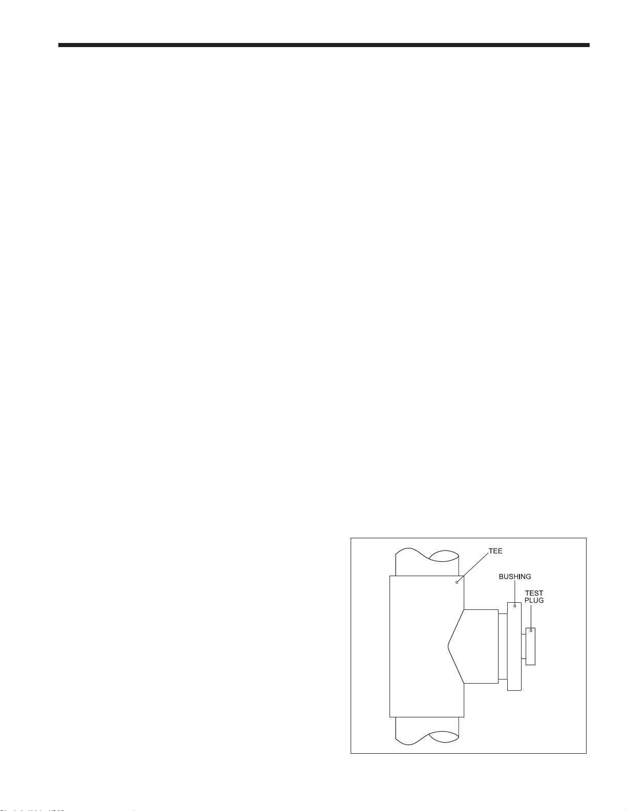
IMPORTANT! It is also the responsibility of the installer
to ensure that a ue gas sampling port is installed in
the vent system. This ue gas sampling port must be
installed near the ue connection of the unit: within
Page 25
NEOT
HERM
Commercial Boilers and Water Heaters, 150 to 850 MBTU/h
Page 21
2 feet of the ue connection. There is no ue gas
sampling port internal to the unit, so one must be
installed in the vent system external to the unit. A ue
gas sampling port available as a component of the
ULC S636 certied vent system is preferred. However,
if one is not available with the certied vent system,
the manufacturer suggests using a tee with the
branch connection sized to allow for insertion of a ue
gas analyzer probe. The branch connection must be
resealable with a cap or other by other means to ensure
the vent system remains sealed. (See Figure 18)
Consideration must be given to the placement and
orientation of the ue gas sampling port to ensure that
condensate is free to ow back into the unit and not
collect anywhere in the vent system - including in the
ue gas sampling port.
An exhaust vent terminal must be installed. If an
exhaust vent terminal is not available with the certied
vent system, the manufacturer suggests the use of a
coupler tting from the certied vent system into which
the vent terminal screen, included with the unit and
shown in the Unpacking section, be installed. Be sure to
install and terminate both vent and combustion air pipes
per the Venting and Combustion Air section of the unit’s
instructions.
3.D Locating Vent and Combustion Air
Terminals
Side Wall Vent Terminal
The appropriate side wall vent terminal must be used.
The terminal must be located in accordance with
ANSI Z223.1/NFPA 54 and applicable local codes. In
Canada, the installation must be in accordance with
CSA B149.1 or .2 and local applicable codes. Consider
the points listed on the following page when installing
the terminal.
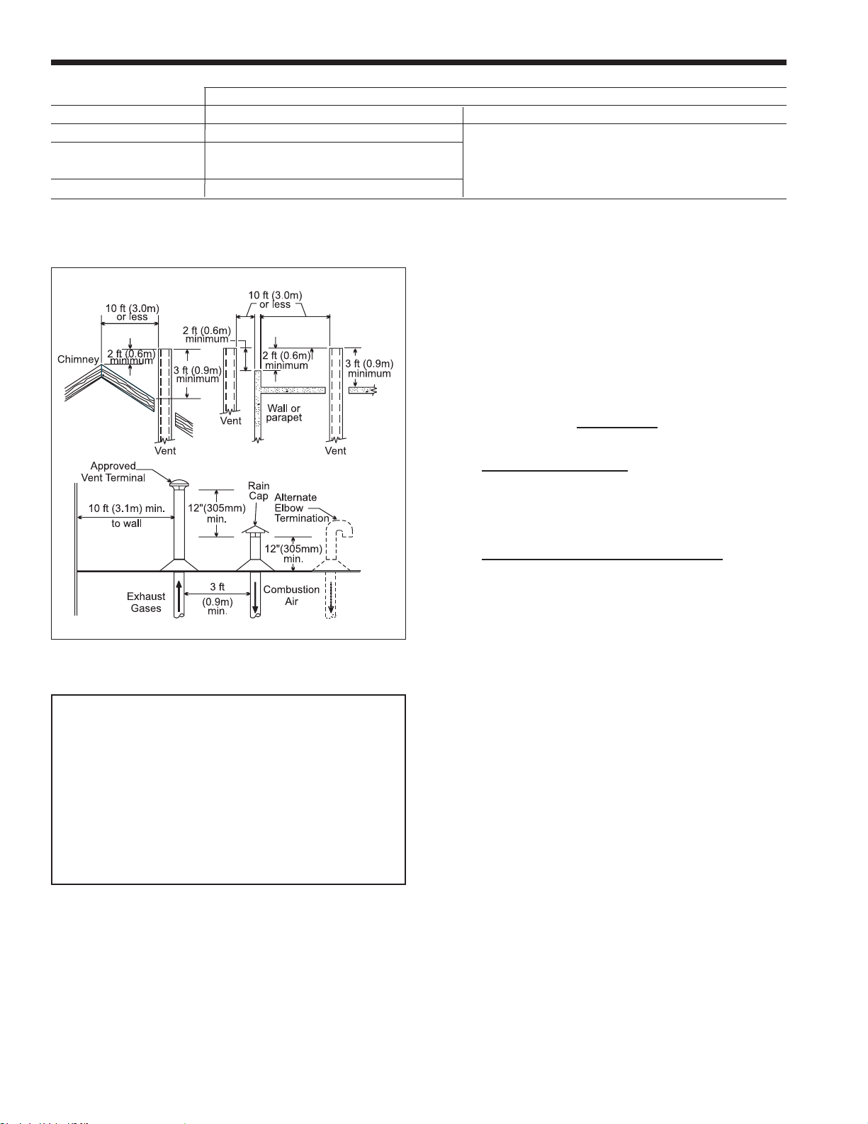
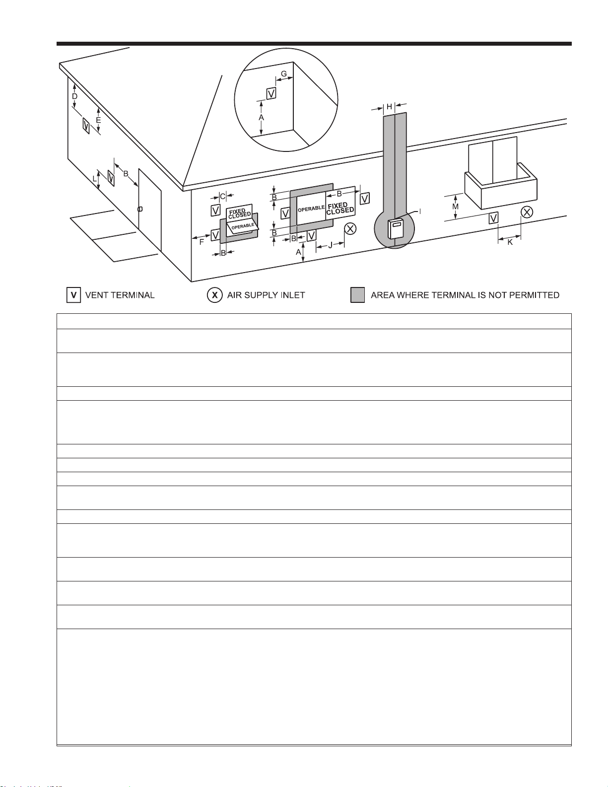
1. Figure 20 shows the requirements for mechanical
vent terminal clearances for the U.S. and Canada.
The outdoor models must be installed at least 10
ft (the vent pipe) from any door or window that
can be opened. The exhaust vent shall not be
under any overhang or roof. Use only the vent
components included with the boiler.
2. Vent terminals for condensing appliances or
appliances with condensing vents are not
permitted to terminate above a public walkway,
or over an area where condensate or vapor could
create a nuisance or hazard.
3. Locate the vent terminal so that vent gases cannot
be drawn into air conditioning system inlets.
4. Locate the vent terminal so that vent gases cannot
enter the building through doors, windows, gravity
inlets or other openings. Whenever possible, avoid
locations under windows or near doors.
5. Locate the vent terminal so that it cannot be
blocked by snow. The installer may determine
that a vent terminal must be higher than the
minimum shown in codes, depending upon
local conditions.
6. Locate the terminal so the vent exhaust does
not settle on building surfaces or other nearby
objects. Vent products may damage surfaces or
objects.
7. If the boiler or water heater uses ducted
combustion air from an intake terminal located on
the same wall.
If the vent termination is located in an area exposed to
high winds, an optional PVC tee (the same diameter as
the vent pipe) may be used. The tee’d vent termination
oers greater protection from wind related operating
issues.
Side Wall Combustion Air Terminal
The side wall combustion air terminal, or concentric
terminal must be used when the heater takes air from
a side wall. (See page 18 ) Contact manufacturer
for AL29-4C termination ttings. Consider the following
when installing the terminal. (See Figure 20 through
Figure 19.)
1. Do not locate the air inlet terminal near a source
of corrosive chemical fumes (e.g., cleaning uid,
chlorine compounds, etc.)
2. Locate the terminal so that it will not be subject to
damage by accident or vandalism. It must be at
least 7 feet (2.1m) above a public walkway.
3. Locate the combustion air terminal so that it
cannot be blocked by snow. The National Fuel
Gas Code requires that it be at least 12 inches
(30cm) above grade, but the installer may
Figure 18. Test Port - ULC-S636 system
Page 26
Page 22
determine it should be higher, depending upon
local conditions.
4. For concentric vent, follow instructions
included with vent kit.
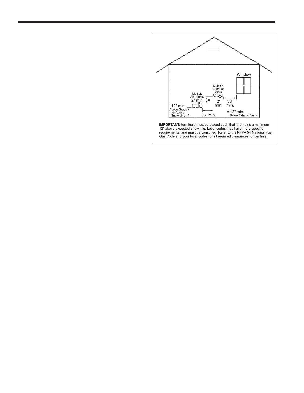
5. Multiple vent kits should be installed such that the
horizontal distance between the outlet group and
the inlet group is 36” (90cm). (Figure 21.)
6. The vent outlet for models 199-285 must be no
lower than the center of the air inlet, and must be
at least 12” (30cm) away from the air inlet. Vent
outlets for models 399-850 must be at least 12”
above the top of the air inlet, and must be at least
36” (90cm) horizontally from the air inlet. (page
24.)
Vertical Vent Terminal
When the unit is vented through the roof, the vent must
extend at least 3 feet (0.9m) above the point at which
it penetrates the roof. It must extend at least 2 feet
(0.6m) higher than any portion of a building within a
horizontal distance of 10 feet (3.0m), and high enough
above the roof line to prevent blockage from snow.
The vent terminal included with the unit can be used
in both vertical and horizontal applications. When the
combustion air is taken from the roof, the combustion
air must terminate at least 12” (30cm) below the vent
terminal. (See Figure 17.)
Vertical Combustion Air Terminal
When combustion air is taken from the roof, a eld-
supplied rain cap or an elbow arrangement must be
used to prevent entry of rain water. (Figure 17.) The
opening on the end of the terminal must be at least 12”
(30cm) above the point at which it penetrates the roof,
and high enough above the roof line to prevent blockage
from snow. When the vent terminates on the roof, the
combustion air must terminate at least 12” (30cm) below
the vent terminal.
Installations in the Commonwealth of
Massachusetts
In Massachusetts the following items are required if the
side-wall exhaust vent termination is less than seven
(7) feet above nished grade in the area of the venting,
including but not limited to decks and porches. From
Massachusetts Rules and regulations 248 CMR 5.08
(begininning on 2nd page following):
1. Installation of Carbon Monoxide Detectors
At the time of installation of the side wall vented gas
fueled appliance, the installing plumber or gas-tter
shall observe that a hard-wired carbon monoxide
detector with an alarm battery back-up is installed
on the oor level where the gas appliance is to
be installed. In addition, the installing plumber or
gastter shall observe that a battery operated or
LAARS Heating Systems
Figure 19. Multiple Side-Wall Terminals,
hard-wired carbon monoxide detector with an alarm
is installed on each additional level of the dwelling,
building or structure served by the side-wall
horizontally vented gas fueled equipment. It shall
be the responsibility of the property owner to secure
the services of qualied licensed professionals
for installation of hard-wired carbon monoxide
detectors.
a. In the event that the side-wall horizontally vented
gas fueled equipment is installed in a crawl space or
an attic, the hard-wired carbon monoxide with alarm
and battery back-up may be installed on the next
adjacent oor level.
b. In the event that the requirements of the
subdivision cannot be met at the time of completion
of installation, the owner shall have a period of thirty
(30) days to comply with the above requirements,
provided, however, that during said thirty (30)
day period, a battery operated carbon monoxide
detector with an alarm be installed.
2. Approved Carbon Monoxide Detectors
Each carbon monoxide detector shall comply with
NFPA 720 and be ANSI/UL 2034 listed and IAS
certied.
3. Signage
A metal or plastic identication plate shall be
permanently mounted to the exterior of the building
at a minimum height of eight (8) feet above grade
directly in line with the exhaust vent terminal for
horizontally vented gas fueled heating appliance or
equipment. The sign shall read, in print no less than
one-half (1/2) inch in size: “GAS VENT DIRECTLY
BELOW, KEEP CLEAR OF ALL OBSTRUCTIONS.”
Page 27
NEOT
HERM
Commercial Boilers and Water Heaters, 150 to 850 MBTU/h
*When vent terminal is less than 10 feet (3m) horizontally
from a forced air inlet, the terminal must be at least 3 feet
(0.9m) above the air inlet. (US only)
Page 23
U.S. Installations (see note 1) Canadian Installations (see note 2)
A= Clearance above grade, veranda, porch, 12 inches (30 cm) 12 inches (30 cm)
deck, or balcony See note 6 See note 6
B= Clearance to window or door that may be Direct vent only: 12 inches (30cm); 36 inches (91 cm)
opened Other than Direct vent: 4 ft (1.2m) below or to NT 80 only - 12 inches (30 cm)
side of opening; 1 ft (30cm) above opening
C= Clearance to permanently closed window See note 4 See note 5
D= Vertical clearance to ventilated sot located
above the terminal within a horizontal See note 4 See note 5
distance of 2 feet (61cm) from the center
line of the terminal
E= Clearance to unventilated sot See note 4 See note 5
F= Clearance to outside corner See note 4 See note 5
G= Clearance to inside corner See note 4 See note 5
H= Clearance to each side of center line 3 feet (91 cm) within a height 15 feet
extended above meter/regulator assembly See note 4 above the meter/regulator assembly
I= Clearance to service regulator vent outlet See note 4 3 feet (91 cm)
J= Clearance to nonmechanical air supply Direct vent only: 12” (30cm) 80-285; 36” (91cm)
inlet to building or the combustion air inlet 399-850. Other than Direct vent: 4 ft (1.2m) below 36 inches (91 cm)
to any other appliance or to side of opening; 1 ft (30cm) above opening NT 80 only - 12 inches (30 cm)
K= Clearance to a mechanical air supply inlet 3 feet (91 cm) above if within 10 feet (3 m) 6 feet (1.83 m)
horizontally
L= Clearance above paved sidewalk or paved Vent termination not allowed in this location 7 ft (2.1 m)
driveway located on public property for category IV appliances. See note 5
M= Clearance under veranda, porch, deck, See note 4 12 inches (30 cm) (see note 3)
or balcony
Notes:
1. In accordance with the current ANSI Z223.1 / NFPA 54 National Fuel Gas Code.
2. In accordance with the current CAN/CSA-B149.1 Installation Codes.
3. Permitted only if veranda, porch, deck, or balcony is fully open on a minimum of two sides beneath the oor.
4. For clearances not specied in ANSI Z223.1 / NFPA 54, clearance is in accordance with local installation codes and the requirements of the
gas supplier.
5. For clearances not specied in CAN/CSA-B149, clearance is in accordance with local installation codes and the requirements of the gas
supplier.
6. IMPORTANT: Terminal must be placed such that it remains a minimum 12” above expected snow line. Local codes may have more
specic requirements, and must be consulted.
Figure 20. Combustion Air and Vent Through Side Wall
Page 28
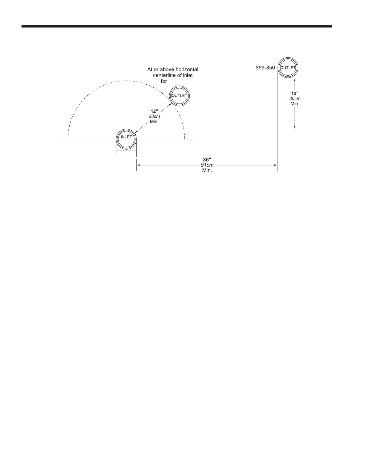
Page 24
150-285
Figure 21. Minimum Venting Distance
LAARS Heating Systems
4. Inspection
The state or local gas inspector of the side-wall
horizontally vented gas fueled appliance shall not
approve the installation unless, upon inspection, the
inspector observes carbon monoxide detectors and
signage installed in accordance with the provisions of
248 CMR 5.08(2)(a) 1-4.
Page 29

NEOT
HERM
Commercial Boilers and Water Heaters, 150 to 850 MBTU/h
Page 25
3.E Common Vent Test
NOTE: This section does not describe a method for
common venting these high eciency condensing units. It
describes what must be done when a unit is removed from
a common vent system. These units require special vent
systems and fans for common vent. Contact the factory if
you have questions about common venting these units.
NOTE: When an existing boiler is removed from a
common venting system, the common venting system is
likely to be too large for proper venting of the appliances
remaining connected to it.
At the time of removal of an existing boiler, the following
steps shall be followed with each appliance remaining
connected to the common venting system placed in
operation, while the other appliances remaining connected
to the common venting system are not in operation.
1. Seal any unused openings in the common venting
system.
2. Visually inspect the venting system for proper size
and horizontal pitch and determine there is no blockage or
restriction, leakage, corrosion and other deciencies which
could cause an unsafe condition.
3. Insofar as it is practical, close all building doors and
windows and all doors between the space in which the
appliances remaining connected to the common venting
system are located and other spaces of the building. Turn
on clothes dryers and any appliance not connected to
the common venting system. Turn on any exhaust fans,
such as range hoods and bathroom exhausts, so they will
operate at maximum speed. Do not operate a summer
exhaust fan. Close replace dampers.
4. Place in operation the appliance being inspected.
Follow the lighting instructions. Adjust the thermostat so
the appliance will operate continuously .
5. Test for spillage at the draft hood relief opening after
5 minutes of main burner operation. Use the ame of a
match or candle, or smoke from a cigarette, cigar or pipe.
6. After it has been determined that each appliance
remaining connected to the common venting system
properly vents when tested as outlined above, return
doors, windows, exhaust fans, replace dampers and any
other gas burning appliance to their previous conditions of
use.
7. Any improper operation of the common venting
system should be corrected so that the installation
conforms to the National Fuel Gas Code, ANSI Z223.1/
NFPA 54 and/or CSA B149.1, Installation Codes. When
resizing any portion of the common venting system, the
common venting system should be resized to approach
the minimum size as determined using the appropriate
tables and guidelines in the National Fuel Gas Code, ANSI
Z223.1 NFPA 54 and/or CSA B149.1, Installation Codes.
REMARQUE : Lorsqu’une chaudière existante est
supprimée d’un système de ventilation commun, le
système de ventilation commun est susceptible d’être
trop grande pour garantir une aération correcte des
appareils restant connecté à elle. Lors de la dépose
d’une chaudière existante, les étapes suivantes
doivent être suivies avec chaque appareil reste
connecté à la système de ventilation commun mis en
opération, alors que les autres appareils connectés
restants à la politique commune de système d’aération
ne sont pas en opération.
1.
Joint les ouvertures inutilisées dans le système de
ventilation commun.
Inspecter visuellement le système de ventilation
2.
à la taille correcte et espacement horizontal et
déterminer il n’y a pas de blocage ou de restriction,
de
fuite, de corrosion et d’autres lacunes que pourrait
causer une condition dangereuse
3.
Dans la mesure où cela est pratique, fermer
tous les bâtiments de portes et fenêtres et toutes
les portes entre l’espace dans lequel les appareils
connectés restants à la système de ventilation
commun
Allumer les sécheuses et tout appareil non connecté
au système de ventilation commun. Mettez sous
tension tous les ventilateurs d’échappement d’air, tels
que les hottes de cuisine et salle de bains exhausts,
an qu’ils fonctionnent à la vitesse maximum. Ne pas
faire fonctionner un ventilateur d’échappement d’été.
Fermer cheminée amortisseurs.
4.
inspecté. Suivez les instructions d’éclairage. Réglez
le thermostat de sorte que l’appareil fonctionnera en
continu.
5.
Test pour les pertes sur les projets d’ouverture de
secours de capot après 5 minutes de fonctionnement
du brûleur principal. Utilisez la amme d’une
allumette ou une bougie allumée, ou de la fumée
d’une cigarette, un cigare ou une pipe.
6.
reste connecté au système de ventilation commun
correctement évents lorsque testé comme décrit
ci-dessus, le retour des portes, des fenêtres,
ventilateurs d’échappement, amortisseurs de
cheminée et tout autre appareil de combustion du
gaz à leurs conditions d’utilisation précédente.
Tout fonctionnement incorrect du système de
7.
ventilation commun devrait être corrigée de sorte
que l’installation est conforme aux code de gaz
combustible National, ANSI Z223.1/NFPA 54 et/
ou CSA B149.1, Codes d’installation. Lors du
redimensionnement de toute portion de la système
de ventilation commun, le système de ventilation
commun doit être redimensionné à l’approche de la
taille minimale, déterminée en utilisant les tableaux
appropriés et des lignes directrices dans le National
sont situés et d’autres espaces du bâtiment.
Place dans le fonctionnement de l’appareil
Après qu’il a été déterminé que chaque appareil
Code de gaz combustible, ANSI Z223.1 NFPA 54 et/
ou CSA B149.1, Codes d’installation.
Page 30

Page 26
LAARS Heating Systems
SECTION 4
GAS SUPPLY AND PIPING
All Installations must conform to the National Fuel
Gas Code ANSI Z223.1/NFPA54, and/or local codes.
In Canada, the installation must conform to the latest
edition of CSA B149.1 Natural Gas and Propane Gas
Installation Code, and/or local codes. Gas piping should
be supported by suitable hangers or oor stands, not
the appliance.
Review the following instructions before proceeding
with the installation.
1. Verify that the appliance is tted for the proper type of
gas by checking the rating plate. The unit will function
properly without the use of high altitude modication
at elevations up to 10,000 feet (3050 m).
2. The maximum inlet gas pressure must not
exceed 13” W.C. (3.2kPa). The minimum inlet gas
pressure is 4” W.C. (1.0kPa).
3. Refer to Table 8 to size the piping.
4. Run gas supply line in accordance with all
applicable codes.
5. Locate and install manual shuto valves in
accordance with state and local requirements.
6. A sediment trap must be provided upstream of the
gas controls.
7. All threaded joints should be coated with
piping compound resistant to action of liqueed
petroleum gas.
8. The appliance and its individual shuto valve
must be disconnected from the gas supply piping
during any pressure testing of that system at test
pressures in excess of 1/2 PSIG (3.45kPa).
9. The unit must be isolated from the gas supply
system by closing its individual manual shuto
valve during any pressure testing of the gas
supply piping system at test pressures equal to or
less than 1/2 PSIG (3.45kPa).
10. The appliance and its gas connection must be
leak tested before placing it in operation.
11. Purge all air from gas lines.
WARNING:
Open ame can cause gas to ignite and result in
property damage, severe injury, or loss of life.
NOTE: This appliance and all other gas appliances sharing
the gas supply line must be ring at maximum capacity to
properly measure the inlet supply pressure. The pressure can
be measured at the supply pressure port on the gas valve.
Low gas pressure could be an indication of an undersized gas
meter, undersized gas supply lines and/or an obstructed gas
supply line. Some units are equipped with low and high gas
pressure switches that are integrally vent limited. These types
of devices do not require venting to atmosphere.
NATURAL GAS
REQUIRED
SIZE
150 150
199/210 199/210
285 285
399 399
500 500
600 600
750 750
850 850
CU FT
/
TO SIZE PIPING:
HR.
Measure linear distance from meter outlet to last
boiler. Add total input of all boilers and divide
by 1000 to obtain cu ft / hr required. Add total
equivalent length of ttings used according to
Table 9. Align total length (pipe and ttings) on left
side column of Table 10 with highest cubic feet of
gas required.
Notes:
Consult and conrm with Applicable Fuel Gas
Code before beginning work. Verify gas inlet
pressure is between 4 and 13 in W.C. before
starting boiler.
Table 8. To Size Your Piping
EQUIVALENT LENGTHS OF STRAIGHT PIPE FOR TYPICAL SCH 40 FITTINGS
NOMINAL PIPE SIZE
FITTING 1/2” 3/4” 1” 1-1/4” 1-1/2” 2”
LINEAR FEET
90° ELBOW 3.6 4.4 5.2 6.6 7.4 8.5
TEE 4.2 5.3 6.6 8.7 9.9 12
T able 9. Equivalent Lengths of Straight Pipe, SCH 40
SCH 40 METAL PIPE CAPACITY FOR 0.60 SPECIFIC GRAVITY NATURAL GAS
NOMINAL PIPE SIZE @ 0.30” W.C. PRESSURE DROP
LENGTH 1/2” 3/4” 1” 1-1/4” 1-1/2” 2”
FT CUBIC FEET OF GAS PER HOUR
20 92 190 350 730 1100 2100
40 130 245 500 760 1450
60 105 195 400 610 1150
80 90 170 350 530 990
100 150 305 460 870
T able 10. Nominal Pipe Size @ 0.30” W.C. Press Drop
SCHED 40 METAL PIPE CAPACITY FOR 1.50 SPECIFIC GRAVITY
NOMINAL PIPE SIZE @ 11” W.C. INLET AND 0.5” W.C. PRESSURE DROP
SIZE 1/2” 3/4” 1” 1-1/4” 1-1/2” 2”
LENGTH MAXIMUM CAPACITY IN THOUSANDS OF BTU PER HOUR
20 200 418 787 1616 2422 4664
40 137 287 541 1111 1664 3205
60 110 231 434 892 1337 2574
80 94 197 372 763 1144 2203
100 84 175 330 677 1014 1952
NOTES:
1. Follow all local and national LP gas codes for line sizing and equipment
requirements.
2. Verify that inlet gas pressure remains between 4 and 13 inches of water
column before and during operation.
Source: ANSI Z223.1-80 National Fuel Gas Code.
T able 1 1. Nominal Pipe Size @ 0.11” W.C. and 0.5” Press Drop
UNDILUTED PROPANE
Page 31

NEOT
HERM
Commercial Boilers and Water Heaters, 150 to 850 MBTU/h
SECTION 5
PUMP REQUIREMENTS
5.A Boiler Flow and Head Requirements Boiler
TEMPERATURE RISE IN °F
20°F 25°F 30°F 35°F 40°F
FLOW H/L FLOW H/L FLOW H/L FLOW H/L FLOW H/L
SIZE GPM FT GPM FT GPM FT GPM FT GPM FT
150 14.3 28.5 11.4 19 9.5 13.6 8.1 11.2 7.1 8.8
199/210 20 24.1 16 16.7 13.4 11.6 11.3 9 9.9 6.9
285 27 25.5 22 17.5 18 14 15 10.5 13 8
399 39 28 31 20 25 14.5 22 11 19 9
500 48 24 38 16 32 12 27 9 24 8
600 58 44 46 31 38 22 33 18 29 15
750 72 37 58 23 48 17 41 13 36 10
850 81 33 65 22 54 15 46 10 41 8
Page 27
TEMPERATURE RISE IN °C
11°C 14°C 17°C 19°C 22°C
FLOW H/L FLOW H/L FLOW H/L FLOW H/L FLOW H/L
SIZE lpm m lpm m lpm m lpm m lpm m
150 54 8.7 43 5.8 36 4.1 31 3.4 27 2.7
199/210 76 7.3 61 5.1 51 3.5 43 2.7 37 2.1
285 102 7.8 83 5.3 68 4.3 57 3.2 49 2.4
399 148 8.5 117 6.1 95 4.4 83 3.4 72 2.7
500 182 7.3 144 4.9 121 3.7 102 2.7 91 2.4
600 220 13.4 174 9.4 144 6.7 125 5.5 110 4.6
750 273 11.3 220 7.0 182 5.2 155 4.0 136 3.0
850 307 10.1 246 6.7 204 4.6 174 3.0 155 2.4
Table 12. Boiler Water Flow Data
5.B Water Heater Flow and Head
Requirements - Heater
NORMAL WATER*
Flow H/L Temp Flow H/L Temp
Size gpm feet Rise °F lpm m Rise °C
150 19 49 15 72 14.9 8
199 25 28 15 95 8.5 8
285 36 33 15 98 10.1 8
399 50 35 15 189 10.7 8
500 63 28 15 239 8.5 8
600** 60 24 19 227 7.3 11
750** 68 35 21 257 10.7 12
850** 68 26 24 257 7.9 13
* Maximum water hardness of 10 grains per gallon allowed.
** See SECTION 6B.7 for pump information.
Table 13. Water Heater Flow Data
Page 32

Page 28
SECTION 6
WATER CONNECTIONS - Part A
Section 6 is divided into two parts. Section
6A covers Boiler units designed for hydronic
heating. Section 6B covers Heater models,
which are designed exclusively for “volume
water” domestic hot water applications. Refer
to the proper section for instructions on
installing and piping your product. Refer to
Table 9 for the connection pipe sizes required.
6.A Boiler
6.A.1 Boiler Water Piping -
NOTE: This appliance must be installed in a closed
pressure system with a minimum of 12 psi (82.7kPa)
static pressure at the boiler.
Water piping should be supported by suitable hangers or
oor stands. Do not support piping with this appliance.
Due to expansion and contraction of copper pipe,
consideration should be given to the type of hangers
used. Rigid hangers may transmit noise through the
system resulting from the piping sliding in the hangers.
It is recommended that padding be used when rigid
hangers are installed. Maintain 1” (2.5cm) clearance to
combustibles for hot water pipes.
Pipe the discharge of the relief valve (full size) to a drain
or in a manner to prevent injury in the event of pressure
relief. Install an air purger, an air vent, a diaphragm-type
expansion tank, and a hydronic ow check in the system
supply loop. Minimum ll pressure must be 12psig
(82.7kPa). Install shuto valves where required by code.
BOILER PIPE SIZE, HEATER PIPE SIZE,
SIZE INCHES SIZE INCHES
150 1 150 1¼
210 1 199 1¼
285 1¼ 285 2
399 1¼ 399 2
500 1½ 500 2
600 1½ 600 2
750 2 750 2
850 2 850 2
LAARS Heating Systems
This unit’s eciency is higher with lower return
water temperatures. Therefore, to get the most of low
return temperature with multiple boilers, pipe as shown in
Figure 22 through Figure 28
Boiler models 150-500 can also be ordered with or
without a pump included.
Units MUST be piped in a primary-secondary fashion
(using either piping or a hydraulic separator) such that
the pump that is mounted on the boiler ONLY serves the
boiler.
When the pump is supplied by the manufacturer, the
boiler must be located within 15 feet (4.6m) of the supply
and return header (or the hydraulic separator). Pumps
supplied by the manufacturer are sized for a maximum
of 30 feet (9.1m) of connection size piping and the
headloss of the boiler only. (See Table 12.)
If longer pipe lengths are required, the pump should
be sized for the boiler and for the piping it will serve.
Even with pumps supplied by others, the manufacturer
strongly recommends primary-secondary piping.
6.A.2 Boiler Cold Water Make-Up
1. Connect the cold water supply to the inlet
connection of an automatic ll valve.
2. Install a suitable back ow preventer between the
automatic ll valve and the cold water supply.
3. Install shut o valves where required.
The boiler piping system of a hot water heating boiler
connected to heating coils located in air handling
appliances where they may be exposed to refrigerated
air circulation must be equipped with ow control valves
or other automatic means to prevent gravity circulation
of the boiler water during the cooling cycle.
A boiler installed above radiation level, or as required by
the authority having jurisdiction, must be provided with a
low water cuto device either as a part of the boiler or at
the time of boiler installation.
Table 14. Water Connection Pipe Sizes
Page 33

NEOT
HERM
Commercial Boilers and Water Heaters, 150 to 850 MBTU/h
6.A.3 Condensate Drain
A condensate drain trap is built into the unit.
No additional or secondary trap is required. .
Connect a 3/4” PVC pipe between the drain connection
and a oor drain (or a condensate pump if a oor drain
is not accessible).
The condensate drain must be installed so as to prevent
accumulation of condensate. When a condensate
pump is not used, the tubing must continuously slope
downward toward the drain with no spiraling. Consult
local codes for the proper disposal method for the
condensate.
If installing in a location that may experience freezing
temperatures, precautions must be taken to prevent
water in the heat exchanger and condensate inside
and outside of the boiler from freezing. Damage due
to freezing water or condensate is not covered by the
warranty.
Page 29
it expands which may result in bursting of pipes, or
damage to the boiler, which could result in leaking or
ooding conditions.
Do not use automotive antifreeze. To help prevent
freezing, the use of inhibited glycol concentrations
between 20% and 35% glycol. Typically, this
concentration will serve as burst protection for
temperatures down to approximately -5°F (-20°C).
If temperatures are expected to be lower than -5°F
(-20°C), glycol concentrations up to 50% can be used.
When concentrations greater than 35% are used, water
ow rates must be increased to maintain a 20°F to 25°F
temperature rise through the boiler.
NOTE: Manufacturers supplied pumps are not all
capable of maintaining the reduced temperature rise
required with glycol concentrations greater than
35%. If glycol concentrations required are greater
than 35% a eld supplied pump should be used.
Caution
Condensate is mildly acidic (pH = 5), and may harm
some oor drains and/or pipes, particularly those
that are metal. Ensure that the drain, drainpipe,
and anything that will come in contact with the
condensate can withstand the acidity, or neutralize
the condensate before disposal. Damage caused by
failure to install a neutralizer kit or to adequately
treat condensate will not be the manufacturer’s
responsibility.
6.A.4 Freeze Protection
WARNING
Glycol must not be used in domestic hot water
applications. Refer to Section 6B.4 for instructions on
Heater, domestic hot water freeze protection.
Indoor units are certied for indoor use only. Outdoor
units are additionally certied for outdoor use.
Proper precautions for freeze protection are
recommended for boiler installations in areas where the
danger of freezing exists.
Power outage, interruption of gas supply, failure of
system components, activation of safety devices, etc.,
may prevent a boiler from ring. Any time a boiler
is subjected to freezing conditions, and the boiler
is not able to re, and/or the water is not able to
circulate, there is a risk of freezing in the boiler
or in the pipes in the system. When water freezes,
Caution
Dierent glycol products may provide varying degrees of
protection. Glycol products must be maintained properly
in a heating system, or they may become ineective.
Consult the glycol specications, or the glycol
manufacturer, for information about specic products,
maintenance of solutions, and set up according to your
particular conditions.
6.A.5 Boiler Suggested Piping Schematics
Figure 22 through Figure 28 show suggested piping
congurations for Boilers. These diagrams are only
meant as a guide. All components or piping required by
local code must be installed.
6.A.6 Recognized Chemicals
The following manufacturers oer glycols, inhibitors,
and anti foamants that are suitable for use in these
units. Please refer to the manufacturers instructions for
proper selection and application.
1. Sentinel Performance Solutions Group
2. Hercules Chemical Company
3. Dow Chemical Company
Page 34

Page 30
LAARS Heating Systems
Figure 22. Hydronic Piping — Single Boiler, Zoning with Circulators
Page 35

NEOT
HERM
Commercial Boilers and Water Heaters, 150 to 850 MBTU/h
Page 31
Figure 23. Hydronic Piping — Single Boiler, Low Temp Radiant Space Heating Using Low Loss Header and
Zone Valves
Page 36

Page 32
Figure 24. Hydronic Piping — Multiple Boilers, Zoning
with Circulators
LAARS Heating Systems
Figure 25. Hydronic Piping — Multiple Boilers with Indirect DHW Tank Piped from System Loop
Page 37

NEOT
HERM
Commercial Boilers and Water Heaters, 150 to 850 MBTU/h
Page 33
Figure 26. Hydronic Piping — Multiple Boilers, Reverse Return, Multi-Temp Zones, Zoning with Circulators
Page 38

Page 34
LAARS Heating Systems
Figure 27. Hydronic Piping — Heating Zones with Indirect DHW Tank Piped with Zone Pumps
The indirect DHW tank is piped directly o of the boiler. The boiler pump must shut down during DHW operation.
Page 39

NEOT
HERM
Commercial Boilers and Water Heaters, 150 to 850 MBTU/h
Page 35
Figure 28. Hydronic Piping, Multiple Boilers with Indirect DHW O of One Boiler
The boiler pump must shut down during DHW operation.
Page 40

Page 36
SECTION 6
WATER CONNECTIONS - Part B
Section 6 is divided into two parts. Section
6A covers Boiler units designed for hydronic
heating. Section 6B covers Heater models,
which are designed exclusively for “volume
water” domestic hot water applications. Refer
to the proper section for instructions on
installing and piping your product. Refer to
Table 14 on page 28 for the connection pipe
sizes required.
6.B Water Heater
6.B.1 Heater Water Quality
Heater water heaters must be installed in water
conditions of 10gpg hardness or less with a pH range
of 8.2 to 9.5. Operating the Heater in water with
higher hardness levels will cause heat exchanger
fouling, erosion, or corrosion leading to premature
component failure, reduced eciency, heat exchanger
failure or system failure. Failure of this type will not be
warranted. If the water in use exceeds the conditions
recommended, a water softener or other device should
be installed to improve water quality.
6.B.2 Piping Requirements
Water piping should be supported by suitable hangers
and oor stands. Do not support piping with the
appliance. Due to expansion and contraction of copper
pipe, consideration should be given to the type of
hangers and supports used. Rigid hangers may transmit
noise through the system resulting from piping sliding in
the hangers. It is recommended that padding be used
when rigid hangers are installed. Maintain 1” (2.5cm)
clearance to combustibles for hot water pipes.
Pipe the discharge of the relief valve (full size) to the
drain or in a manner to prevent injury in the event of
pressure relief. Install a diaphragm-type expansion
tank, ow check, and shuto valves where needed or as
required by code.
This unit 150-500 can be ordered with pumps. Whether
the factory pumps or other pumps are installed, the
piping should be installed such that the pump supplies
ow to the heater it is attached to only. The factory
pumps are sized for 30 feet and 6 elbows of total pipe
length, so the heater should be placed within 15 feet of
the tank. If longer runs are required, a properly-sized
eld-supplied pump should be used.
See Section 5.2 and Table 13
6.B.3 Cold Water Make-Up
The cold water make-up may be connected to the tank
LAARS Heating Systems
or to the inlet of the boiler as shown in Figure 29 through
Figure 32. Install back ow preventers and shut os
where needed or required by code. Pipe sizes may
have to be increased to accomodate cold water makeup ow.
6.B.4 Condensate Drain
A condensate drain trap is built into the unit.
Connect a 3/4” PVC pipe between the drain connection
and a oor drain (or a condensate pump if a oor drain
is not accessible).
The condensate drain must be installed so as to prevent
accumulation of condensate. When a condensate
pump is not used, the tubing must continuously slope
downward toward the drain with no spiraling.
Consult local codes for the proper disposal method for
the condensate.
Caution
Condensate is mildly acidic (pH = 5), and may harm
some oor drains and/or pipes, particularly those
that are metal. Ensure that the drain, drainpipe,
and anything that will come in contact with the
condensate can withstand the acidity, or neutralize
the condensate before disposal. Damage caused by
failure to install a neutralizer kit or to adequately
treat condensate will not be the manufacturer’s
responsibility.
6.B.5 Freeze Protection
These un are certied for outdoor use but they should not
be subjected to freezing temperatures. In an event such
as power outage, component failure or other issue when
freezing is likely , the heater and system must be drained to
avoid the risk of damage due to freezing. Glycol must not be
used in volume water heating applications.
6.B.6 Heater Suggested Piping Schematics
Figure 29 through Figure 32 show suggested piping
congurations for Heater boilers. These diagrams are
only meant as guides. All components or piping required
by local code must be installed.
6.B.7 Heater Suggested Pumps
Possible pumps for Heater sizes 600-850 are Grundfos
model TP 40-160/2B, or for size 600 (only) is Armstrong
model E22B. See Table 13 for heater water ow and head
requirements.
Note - The head loss for the piping, ttings, and
accessories must be calculated and added to the heater
head loss to get the total required pump head. An
undersized pump will result in insucient ow which can
result in scale buildup and failure of the heat exchanger.
Page 41

NEOT
NOTES:
1. Optional CWMU & Recirc. line location.
2. Locate Heater DHW sensor or remote aquastat well
in lower 1/3 of tank.
3. Back ow preventer may be required - check local codes.
4. Thermal expansion tank may be required - check local codes.
5. Factory mounted pumps are sized for a max pipe length of
30’ total, 6-90° elbows, full pipe size.
6. Caution: Pump sizing must be based on water hardness at job site.
HERM
Commercial Boilers and Water Heaters, 150 to 850 MBTU/h
Page 37
WARNING: This drawing shows
suggested piping conguration and
valving. Check with local codes and
ordinances for additional requirements.
Figure 29. DHW Piping, One Heater, One Vertical Tank
NOTES:
1. Optional CWMU & Recirc. line location.
2. Locate Heater DHW sensor or remote aquastat well in lower 1/3 of tank.
3. Back ow preventer may be required - check local codes.
4. Thermal expansion tank may be required - check local codes.
5. Factory mounted pumps are sized for a max pipe length of
30’ total, 6-90° elbows, full pipe size.
6. Caution: Pump sizing must be based on water
hardness at job site.
Figure 30. DHW Piping, One Heater, Two Vertical Tanks
WARNING: This drawing shows
suggested piping conguration and
valving. Check with local codes and
ordinances for additional requirements.
Page 42

Page 38
WARNING: This drawing shows
suggested piping conguration and
valving. Check with local codes and
ordinances for additional requirements.
LAARS Heating Systems
NOTES:
1.
Optional CWMU & Recirc. line location.
2.
Locate Heater DHW sensor or remote aquastat
well in lower 1/3 of tank.
3.
Back ow preventer may be required - check
local codes.
4.
Thermal expansion tank may be required -
check local codes.
Factory mounted pumps are sized for a max
5.
pipe length of 30’
6. Caution: Pump sizing must be based on
water hardness at job site.
total, 6-90° elbows, full pipe size.
Figure 31. DHW Piping, Two Heaters, One Vertical Tank
NOTES:
1. Optional CWMU & Recirc.
line location.
2. Locate Heater DHW sensor
or remote aquastat well
in lower 1/3 of tank.
3. Back ow preventer may be
required - check local codes.
4. Thermal expansion tank may be
required - check local codes.
5. Factory mounted pumps are sized
for a max pipe length of 30’ total,
6-90° elbows, full pipe size.
6. Caution: Pump sizing must
be based on water
hardness at job site.
WARNING: This drawing shows
suggested piping conguration and
valving. Check with local codes and
ordinances for additional requirements.
Figure 32. DHW Piping, Two Heaters, Two Vertical Tanks
Page 43

NEOT
HERM
Commercial Boilers and Water Heaters, 150 to 850 MBTU/h
SECTION 7
INST ALLATION AND WIRING
7.A Installation Warnings
WARNING
The appliance must be electrically grounded in
accordance with the requirements of the authority
having jurisdiction or, in the absence of such
requirements, with the latest edition of the National
Electrical Code, ANSI/NFPA 70, in the U.S. and with
the latest edition of CSA C22.1 Canadian Electrical
Code, Part 1, in Canada. Do not rely on the gas or
water piping to ground the metal parts of the boiler.
Plastic pipe or dielectric unions may isolate the boiler
electrically. Service and maintenance personnel, who
work on or around the boiler, may be standing on wet
oors and could be electrocuted by an ungrounded
boiler. Electrocution can result in severe injury or
death.
Single pole switches, including those of safety
controls and protective devices, must not be wired in
a grounded line.
All electrical connections are made on the terminal
blocks that are located inside the control panel.
Wiring connections are shown in Figure 34.
All internal electrical components have been
prewired. No attempt should be made to connect
electrical wires to any other location except the
terminal blocks.
Caution
The supply voltage to the unit must not be
disconnected, except for service or isolation, or
unless otherwise instructed by procedures outlined
in this manual. To signal a call for heat, use the 24V
eld interlock, as shown in the wiring diagram.
DO NOT MAKE AND BREAK THE LINE VOLTAGE
TO THE UNIT TO SIGNAL A CALL FOR HEAT.
A call for heat/ end call for heat MUST be connected
to the eld interlock terminals. Some components
are designed to have constant voltage during normal
operation. If the units’s supply voltage is toggled
as a call for heat signal, premature failure of these
components may result.
The unit does not recognize 4mA as a call for heat.
If the call for heat is not connected between the
eld interlock terminals, the unit will remain in low
re when it sees 4mA as a modulating signal. See
Section 7.4 for more details.
Page 39
7.B Main Power Connections
Connect a 15A fused, 120-volt supply to the main power
switch. (The hot leg is connected directly to the switch.)
The neutral leg is connected directly to the white wire.
The ground wire can be connected to the grounding lug
on the control panel.
See Figure 33 on page 40 for all references to power
connections in Section 7.
7.B.1 Pump Connections and Operation
The controller in the unit energizes the pump contacts
when it receives a call for heat. Once the call for heat is
satised, the pump will remain on for the dened pump
overrun time.
The Boiler Pump terminals (TB5 - max 7.4 FLA) are
fed by 120V (violet wire) internally from the main power
feed. The System and DHW contacts are dry contacts.
Appropriate voltage must be supplied to the System
and DHW pumps for proper operation.
The System pump connections are located on terminal
block 5 (TB5) in the control panel. (See Figure 33.) The
System pump contacts are rated for 120Vac, 7.4 Amps.
To use the contacts, power must be supplied on one
terminal with the other terminal wired to the pump or a
relay controlling the pump.
The DHW pump connections are located on terminal
block 5 (TB5) in the control panel and are rated for
120Vac, 7.4 Amps. To use the contacts, power must be
supplied on one terminal, and the other terminal wired
to the pump or a relay controlling the pump.
Additional 120VAC circuits may be required for the
pumps.
7.B.2 Optional VARI-PRIME
VARI-PRIMETM is a variable speed pump control
that is optional equipment on all commerical boilers.
Pump speed is controlled to maintain a user-chosen
temperature rise between the inlet and outlet of the unit.
VARI-PRIME will operate the boiler pump at
maximum ow during boiler startup to ensure stable
operation is reached before introducing variable water
ow. This key feature keeps the boiler’s combustion
and variable speed pump’s ow in phase with each
other, protecting the heat exchanger from potential low
ow conditions.
Contact your manufacturers representative for more
details.
TM
Page 44

Page 40
Page 38
LAARS Heating Systems
LAARS Heating Systems
Figure 33. Power & Control Panel Layout
Factory
installed
100Ω
resistor
Figure 34.
Outdoor Sensor Jumper on W
All water heating units are shipped
from the factory with a resistor (jumper)
between the outdoor sensor terminals
(terminals 1 and 2 on TB7). If this
resistor is removed, the water heater will
not be able to heat water above 140°F.
ater Heaters
Page 45

NEOT
HERM
Commercial Boilers and Water Heaters, 150 to 850 MBTU/h
7.C Hydronic Heating Using External
Modulation Control
About External Control -
When the unit is used for hydronic heating with external
modulation control, a call for heat must be supplied to
the “T-T or Interlock” terminal. Once the call is supplied
the control starts the Boiler and System pumps and
begins the ignition process. Once in Run, the unit
monitors the ame signal, call for heat, safeties, and
water temperatures. The boiler setpoint is used to limit
the maximum water temperature leaving the boiler
only. The modulation rate is controlled by a 4-20mA
signal supplied by an external control. (This can also be
0-10Vdc using a converter - part number CA006100.)
When setting up a system using an external control,
take care to set Anti-Short Cycle feature to prevent
“hunting “ and possible premature component failure.
Page 41
BOILER
PUMP CONNECTIONS
SIZES VOLTS PHASE AMPS
199–850 120 Single 2* 115V – Maximum 1HP
No Pump or 7.4A max
199-500 Less
With Pump 120 Single than
6*
*
Minimum 15A circuit required
RATINGS
(Boiler, System Pump and
DHW Pump Connections)
115V – Maximum 1HP
or 7.4A max
Table 15. Boiler Electrical Data
7.D Optional Field Connections
Terminal block 8 (TB8) in the control panel is used for the
‘Safety Chain’ and for connecting optional components
such as low water cutos, ow switches, additional high
limits, and other eld-supplied devices that must be
interlocked with the boiler. These are non-powered dry
contacts only. All safeties or end switches must be wired
in series by removing the supplied jumpers.
See Figure 33
NOTE: When installing any eld-supplied options like
Low Water Cuto, High Limits, or a Flow Switch, always
remove the jumper that is factory installed at that location
on the TB8 block.
SIZES VOLTS PHASE AMPS
199-500 120 Single 2*
No pump
199 120 Single 7*
With pump
285-500 120 Single 8*
With pump
600-850 See Pump Rating Plate FLA
No pump (must be less than 7.4 FLA)
Minimum 15A circuit required
*
Table 16. Heater Electrical Data
WATER HEATER
Page 46

Page 42
TO CASCADING
UNITS 3 THRU 8
(TYP)
TO CASCADING
UNITS 3 THRU 8
(TYP)
COM2
C
B
A
LAARS Heating Systems
7.E Lead Lag Connections
These units can be connected in a Lead Lag series up to a
total of 8 controllers. One as the Lead control and 7 more as
the following controllers. See Figure 35.
For general info and menu set-up for Lead Lag using your
Touchscreen, See Section 8, page 58 ‘About Lead Lag’.
Lead Boiler
Gateway
Control
(H2354400
Doc# 4236)
Figure 35. Wiring Diagram for Lead Lag Connections and
the Gateway Building Automation System
Page 47

NEOT
TO CASCADING
UNITS 3 THRU 8
(TYP)
TO CASCADING
UNITS 3 THRU 8
(TYP)
COM2
C
B
A
TO CASCADING
UNITS 3 THRU 8
(TYP)
TO CASCADING
UNITS 3 THRU 8
(TYP)
COM2
C
B
A
HERM
Commercial Boilers and Water Heaters, 150 to 850 MBTU/h
Following Boiler
Page 43
7.F Building Automation
System Connections
These units can be controlled and
monitored through the included
Modbus ports.
Gateway Control (H2354400 Doc#
4236).
Connect the 4-20mA signal from
an external control or building
automation system to terminal
block 7 (TB7) in the control panel.
See Figure 33. The connections
are labeled Remote Analog Input.
When making the connections,
follow the polarity designations
shown on the label.
Signals from a Building Automation
System can be connected to the
MB2 Modbus connections on the
controller.
See Figure 35.
For additional information on
setting up Modbus and other
communication protocols, contact
the factory.
Page 48

Page 44
PRESSURE
SWITCH
BR
OR/WH
B
R
O
R
/
W
H
NC
COM
TABLE 1 -COLOR ABBREVIATIONS
BL = BLUE
BLK = BLACK
BRN = BROWN
CL - CLEAR
DKB = DARK BLUE
GN = GREEN
GY = GRAY
LTGN = LIGHT GREEN
OR = ORANGE
PUR = PURPLE
R = RED
TN = TAN
VT = VIOLET
WH = WHITE
Y = YELLOW
TABLE 2 - GAS VALVE WIRE COLORS
GAS VALVE PIN NO. 80-285 399-500 600-850
YRBY1
KBLB-2
LB-BKD3
NRGANNG4
GY/BL
Y
THERMO-FUSE
(ON SOME MODELS)
GY
CONDENSATE
LEVEL SWITCH
TRANSFORMER
110VAC INPUT
24VAC OUTPUT
TB8 FIELD
CONNECTIONS
OUTLET
TE
SENSOR
(P2)
T
-
T
O
R
IN
T
E
R
L
O
C
K
A
N
A
L
O
G
IN
P
U
T
+
A
N
A
L
O
G
IN
P
U
T
-
O
U
T
D
O
O
R
T
E
M
P
S
E
N
S
O
R
TB7
FIELD
CONNECTIONS
SAFETY
CHAIN
TB4
24V
COMMON
TB3
24V
"HOT"
Y
R
T
N
T
N
/
Y
B
R
B
R
/
W
H
R
/
Y
R
GY/R
Y
DKB
Y
BLK
WH
R
Y
GY/BL
Y
GY/R
LOW
WATER
CUTOFF
FIELD INSTALLED
OPTIONS
WH/GY
GR/VT
GR/BL
Y
BL
ADD'L
HIGH
LIMIT
R
FLOW
SWITCH
TO TB1 PIN2
TO TB2 PIN2
W
H
/
G
Y
B
L
G
R
/
B
L
R
G
R
/
V
T
G
Y
/
R
W
H
/R
/G
N
TO J6-2
Y
TO J4-10
O
U
T
D
O
O
R
T
E
M
P
S
E
N
S
O
R
TO
GAS
VALVE
P1
1
2
2
1
61
6
1
6
1
Y
W
H
&
G
R
TB6
FIELD
CONNECTIONS
A
L
A
R
M
TO J6-7
TO J6-8
B
L
B
L
/
Y
O
R
/
B
L
K
W
H
/
G
Y
W
H
/O
R
A
L
A
R
M
D
H
W
T
E
M
P
S
E
N
S
O
R
B
L
K
/
O
R
A
Q
U
A
S
T
A
T
O
P
T
IO
N
S
Y
S
T
E
M
S
E
N
S
O
R
TABLE 1.
COLOR ABBREVIATIONS
OPTIONAL SWITCH
USED ON SOME
MODELS. IF SWITCH
IS NOT INSTALLED IN
THIS LOCATION. THE
TERMINAL JUMPER
SHOULD BE IN PLACE
GY/WH
1
7.G System Wiring Diagram
LAARS Heating Systems
Figure 36. Wiring Diagram, All Sizes
Page 49

BOILER
PUMP
GND
BLK
WH
GN
COM 2
24Vac
24V com
1
2345678
TO TB4-1
TO TB3-1
COM 1
BL/GN
Y/GN
NOTES:
ALL CONNECTORS ARE VIEWED FROM REAR 1.
OF CONNECTOR (INSERTION END)
H2355400C
GY/BL
GY/WH
GY
Y
CONDENSATE
LEVEL RELAY
7 8
5
3
1 2
4
6
GY/RD
BOILER PUMP
INTERRUPT
JUMPERS
V+
V-
A
OR/GN
LTGN
DISPLAY
TOUCH-SCREEN
2
43
21
43
21
HIGH/LOW
GAS PRESSURE
SWITCH
500-850 CSD-1 ONLY
FLAME
ROD
BLOWER
GND
HV
SPARK
P5
P4
3
1
5
1
J6-1
J6-2
3 1
2
GND
STACK
TEMP
(P3)
INLET
TEMP
SENSOR
(P1)
OUTLET
TE
MP
SENSOR
(P2)
J9-1
J9-2
J9-4
J9-5
J9-6
J2-4
J2-3
J2-2
J2-1
J8-1
J8-2
J8-6
J8-7
J8-8
J8-9
J8-10
J8-11
J8-12
J5-2
J5-1
J4-2
J4-3
J4-4
J4-5
TB5
BOILER
CONNECTIONS
J4-7
GND
J4-12
J4-10
J4-6
SW 1
TB2
110V
NEUTRAL
TB1
110V
"HOT"
BLK
WH
GR
CUSTOMER
POWER INPUT
CONTROL MODULE
(Honeywell)
R
PUR
PUR/BLK
WH/BL
DKB
DKB/Y
DKB
FS-2
DKBDKB
WH/BL
WH/BL
WH/R
WH/R
FS-1
DKB/Y
PK
R/BLK
WH/GN
GR/R
W
H
CL
CL
CL
CL
CL
WH/R/GN
TN/BRN
OR
TN/BL
TN/R
Y
VT
WH
W
H
BLK
BLK
BLK
TO
XFORMER
WH
TO XFORMER
WH/R
BRN/WH
BRN
R/Y
PUR
PUR/BLK
TN/Y
TN
WH
TN/BLK
WH/OR
WH/GY
TO TB6 P2
TO TB6 P1
TO TB4-P1
GY
DKB
GY
BLK
TO TB8 P1
BLK
WH
GR
CRIMP NUT
GY
NEUTRAL
L
PUMP
NEUTRAL
L
FIELD
OPTIONS
DRY CONTACTS
ONLY SEE I/O
MANUAL SECT 5.3
WH
WH
1
6
1 2
1 2
GY
J1-2
J1-3
SPARK
IGNITOR
P
U
R
O
R
PUR
OR
PRESSURE
SWITCH
3
2
1
4
GAS
VALVE
GND
SEE
TABLE 2
2
3 7
J10-7
J10-8
OR/BLK
BLK/OR
MS-2
MS-1
R2
R1
6
4
21
3
5
87
PUMP
BYPASS
RELAY
BRN
BRN
OR
TN/BRN
WH
TN/BLK
TN/BL
TAN/R
BLK/Y
BLK
Y
GR
BLK/Y
VT
COM
NO
FACTORY INSTALLED
OPTION FOR 500 -850
CSD-1 ONLY
DHW
SYS
PUMP
J8-3
J8-4
J8-5
SEE
TABLE 2
J6-3
J6-7
J6-8
TO TB4
DKB/Y
BL
OR
OPTIONAL SWITCH
USED ON SOME
MODELS. IF SWITCH
IS NOT INSTALLED IN
THIS LOCATION. THE
TERMINAL JUMPER
SHOULD BE IN PLACE
THERMO-FUSE
GND
B
VDC
A
B
ECOM
MB2
MB1
NEOT
HERM
Commercial Boilers and Water Heaters, 150 to 850 MBTU/h
Page 45
Page 50

Page 46
7.H Ladder Diagram
LAARS Heating Systems
Figure 37. Ladder Diagram
Page 51

NEOT
HERM
Commercial Boilers and Water Heaters, 150 to 850 MBTU/h
SECTION 8
USING THE TOUCH SCREEN
The Touch Screen
on OUTDOOR
units is located
behind the front
panel.
Page 47
e home screen shows a picture of the unit’s controller. e
color of the controller depends on the status, as shown below.
Color Status Control
Icon
Blue Normal operation
Red Lockout
Gray Standby mode (Burner
switch o )
Figure 38. Touch Screen
8.A The Touch Screen
The Touch Screen is located front and center on
the units and allows you to navigate into all of the
functionality and control that is available to setup and
customize your heating and/or hotwater system.
8.B Using the Touch Screen
A screen saver is programmed into the display. Simply
touch the screen to wake it up.
While under normal operation, the Touch Screen will
automatically present this Home Screen. See Menu 1
Gray and
crossed
out
Yel l o w Hold state. is could
Figure 39. Boiler Status Colors
To check the operation of the appliance, press
the large Control Icon on the Home screen. The
system will present a Status Summary screen for the
appliance:
Communication problem
be Anti short cycle, fan
speed transitions, etc.
Menu 1. Home Screen
Menu 2. Status Summary
Page 52

Page 48
LAARS Heating Systems
Screen Menu Icons
There are several icons at the top of the Touch Screen
Menus (and most of the other screens) that will help
you move around the system:
Home Upper left-hand
corner
Camera Upper left-hand
corner
Bell Upper left-hand
corner
Padlock Upper right-hand
corner
Back Upper right-hand
corner
Sometimes a screen is used to present a list, and often
the list is too long to present on a single screen view. To
see the rest of the list, pull down on the bar on the right
side of the screen, or use the up- and down-arrows.
To make a change, or to get more information about one
of the items on the list, press on the line for that item.
Return to Home page
Screen-shot of current
menu as a JPG le
System in Lockout,
Reset required
Locked or Unlocked.
See Menu 3
Return to previous
to go through an additional “verication” process. For
more information, see the section on “Conguration.”)
When a password is necessary, the system will present
the keyboard screen. See Menu 3.
lnt
Menu 3. Keyboard Screen
The passwords used by this system are “case
sensitive” – it matters whether a letter in the password
is capitalized or not. Pressing the Shift key toggles
between capital and lower case letters.
“BS” stands for “Back Space,” and also works as a
Delete key.
Anyone can view all of the parameters. However,
to change most of the parameters, you will need a
password.
At the bottom of the screen, the system indicates that
you need to enter a password.
8.C Login (required for some parameters)
To change some parameters, a Login (password) is
required. The control system includes three levels of
password protection:
OEM Factory Password Setup and parameter
changes Available only to the factory.
Login Installer Password
Setup and parameter changes made
when the system is installed, and some
diagnostic and troubleshooting functions.
The installer level password is “lnt” (lower
case “LNT.”) See Menu 3
User (no password required)
Non-critical adjustments and functions,
including adjusting the Central Heat and
Domestic Hot Water setpoints, monitoring
the input and output variables, reading
parameters from the controller, and reading
the error log
(For some special safety-related functions, besides
entering the correct password, the system will ask you
Menu 4. Login Required
The screen used to Login is similar to the Keyboard
screen.
It may be dicult for some operators to press the keys
on this screen. In this case, use the back of a plastic
pen, or a stylus, or a pencil eraser. (Do not use sharp
metal tools – these may damage the plastic surface of
the screen.)
Each time you press a key, the system will respond with
a beep. If you are entering a password, an asterisk (*)
will appear for each character you enter. The beeps
and asterisks will help you enter the correct number of
Page 53

NEOT
HERM
Commercial Boilers and Water Heaters, 150 to 850 MBTU/h
Page 49
characters for your password.
When changing a numerical value, the system
presents a numerical entry screen, as shown below.
Menu 5. Numeric Entry Screen
8.D Verication Process for Safety-
Related Parameters
The verication process allows the user to
conrm that all the changes made are correct
and that there have not been any inadvertent
changes made.
1. When you start to change a parameter that
is related to safety, the system will present a
warning which looks like this:
2. If you make a change in any group that could
aect the safe operation of the unit, the control
system will ask you to “verify” the change before
it is accepted.
3. Once all parameters have been changed, return
to the congure menu. In the lower right hand
corner of the screen you will see ‘VERIFY’ Press
VERIFY, then press BEGIN to start verication.
Notes –
• Once you change one of these safety-related
parameters, you must nish the verication process
for the group that includes the parameter, or the
control system will not let the boiler operate. Y ou
can wait to do the verication until you have changed
parameters in other groups, but before you return the
boiler to service, you must complete the verication
process for all groups that have been changed.
• At the end of the verication process, you must press
the Reset button on the front of the controller. See
Figure 40. You have to do this within 30 seconds, or
the verication will be cancelled. To make it easy to
reach the Reset button, open the door on the front
of the boiler and slide out the control panel before
beginning the verication.
Menu 6. Parameter Safety Warning
WARNING
Changing safety parameters should only be
conducted by experienced, licensed boiler operators
and mechanics. Hazardous burner conditions can
happen with improper operations that may result in
PROPERTY LOSS, PHYSICAL INJURY, or DEATH.
Press OK to continue. The system will ask you
to login before you make a change. (For more
information on logging in, see Section 8.2.)
Figure 40. Reset Button on Controller
4. The system will present a listing for each group
of parameters that need verication
See Menu 7.
Page 54

Page 50
Menu 7. Safety Parameter Conrmation
5. For each group, check the list carefully. Press
Yes if all of the parameters in the group have
been entered correctly. For each group, you are
given 30 seconds to select Yes/No.
A count-down timer is shown at the bottom of the
screen.
If you made changes in other safety-related
groups, verify the entries in those groups in the
same way. Do this until the following screen
shows
LAARS Heating Systems
8.E Checking Individual Parameters
1. From the ‘Home’ screen (Menu 9), press the icon
for the controller.
Menu 9. ‘Home’ screen
2. The Status Summary page for the controller will
appear. This shows the current operating condition
of the controller, and also shows some of the
conguration settings.
See Menu 10
Menu 8. Safety Parameter Reset
6. When the process is complete, the system will
tell you to reset the control system. The Reset
button is located on the front of the controller.
You must press the Reset button within 30
seconds, or the verication will be cancelled. A
count-down timer is shown at the bottom of the
screen.
Menu 10. Status Summary Screen
Notice the four buttons at the bottom of each
Status Summary screen:
• Congure – Allows an installer to change some
of the setup parameters used by the system. A
password may be required.
• Operation – Used to adjust the setpoints,
change the fan speed, turn a burner on or o, or
turn the pumps on or o.
• Diagnostics – Allows you to run diagnostic tests,
or check the inputs and outputs used by the
system.
• Details – Allows you to check the status of all of
the setup parameters on the control system.
Page 55

NEOT
HERM
Commercial Boilers and Water Heaters, 150 to 850 MBTU/h
8.F Setting the Date and Time on the
System Display
The display includes an internal clock, which keeps
track of the date and time. This setting is important,
because log entries for Lockouts and Alerts include time
listings. If the Date and Time setting for the boiler is not
correct, the listings in the Lockout and Alert logs will be
incorrect.
To set the clock:
1. Start at the ‘Home’ screen.
Page 51
Menu 13. Display Setup Screen
4. Press ‘Set Date/Time’ button.
Menu 11. ‘Home’ screen
2. Press the Setup button on the lower right corner
of the screen. The system will present the Setup
screen.
Menu 12. Setup Screen
3. Press the Display Setup button at the bottom of
the screen.
Menu 14. Date and Time
5. Use the arrows to change the date and time,
and then press the OK button.
Battery
The display has a removable battery (CR2032) to
store time, date, lockout, and alerts in the event of a
power failure. It has an expected lifetime of 10 years.
The battery can be accessed from the back of the
Touchscreen display.
(Back)
Battery ( CR2032 )
Page 56

Page 52
8.G The Conguration Menu
is the gateway to the parameters that the
factory, the installer, or the end user will need in order
to setup, service, maintain, or adjust the unit.
There are eighteen (18) items in the Conguration
Menu that can be viewed. Please Review Menu 17.
Each of these items will have Sub-Menus in which you
can make parameter adjustments and congurations.
LAARS Heating Systems
8.7.1
8.7.2
8.7.3
8.7.4
8.7.5
1. From the Home Page screen (Menu 15), press
the icon for the controller.
Menu 15. Home Screen
2. The Status Summary page for that controller will
appear. See Menu 16
8.7.6
8.7.7
8.7.8
8.7.9
8.7.10
8.7.11
8.7.12
8.7.13
8.7.14
8.7.15
8.7.16
8.7.17
8.7.18
Menu 17. The Conguration Menu
From the Conguration Menu there are
18 Conguration Sub-Menus. Use the scroll tab on the
right to view them all.
The next section of this manual will show the installer
these sub-menus and the basics on how to setup/adjust
these congurations.
Menu 16. Status Summary Screen
3. Press the Congure button to start a conguration
session for the controller.
Page 57

NEOT
HERM
Commercial Boilers and Water Heaters, 150 to 850 MBTU/h
The Conguration Sub-Menus ( ALL 18 )
8.G. 1
__
18
Page 53
8.G.2.b Setting Up 4-20 mA Setpoint
Some of these congurations will require a Login rst.
See Menu 3 on page 48
When using the unit for hydronic heating, a call for
heat must be supplied to the “T-T” terminals found on
TB7 labeled “T-T or Interlock”. Once a call for heat
is established, the control will start the appropriate
(selected) pumps, and begin the ignition process.
8.G.1 System Identication & Access
This sub-menu will display information regarding software,
date codes, model numbers and program name, as well
as giving the installer access to re-name the boiler and
to change the modbus addresses for lead lag operation.
Press the back arrow on the top right corner of the screen
to return to the ‘Conguration Menu’.
The Central Heat Conguration Menu ( ) has three
sub-menus and each of them can be reached by
scrolling left or right thru the arrows on the left and
right. See Menu 18. The three sub-menus are
‘Central Heat’, ‘Setpoint’, and ‘Modulation’.
To set up 4-20 mA Setpoint, you will need to go into
the ‘Setpoint’ sub-menu rst and change the Setpoint
source from Local to S2 (J8-6) 4-20 mA. Then go to
the ‘Modulation’ sub-menu and set the Modulation
source to Local. Both Setpoint and Modulation
cannot have their source set as Local.
From the Central Heat Conguration Sub-Menu,
choose either the left or right arrow.
Menu 18. The Setpoint submenu
until you are on the ‘Setpoint’ sub-menu,
then Click onto ‘Local’.
8.G.2 Heat Conguration
8.G.2.a CH - Central Heat Conguration
Make sure that CH is Enabled and then press one of the
black arrows (either side) to get to the Set-Point screen.
Press on the ‘Setpoint’ box to make adjustments to
setpoint, and modulation for a single boiler CH demand.
Click onto the down arrow to see further options.
Page 58

Page 54
LAARS Heating Systems
Choose S2 (J8-6) 4-20 mA, then press OK
Then scroll over to the Modulation sub-menu and
click onto Modulation rate source.
8.G.3 Outdoor Reset Conguration
At this sub-menu, conrm that Central Heat is Enabled.
Next, press onto the Maximum Outdoor Temperature,
Minimum Outdoor Temperature, and Low Water
Temperature to get to each and adjusting their setpoints in
those sub-menus.
8.G.4 DHW - Domestic Hot Water
Conguration
Select Local, then press OK.
DHW - Domestic Hot Water is used to congure the
DHW temperature parameters for water heaters
(Heater) and for indirect water heaters that are used
with boiler (Boiler) systems.
Press on the Setpoint box to get to the adjustment submenu.
setpoint.
Then adjust it up or down to your desired DHW
8.G.5 Warm Weather Shutdown
Conguration
From this sub-menu you will be able to enable/disable the
Warm Weather Shutdown feature and adjust the set
point.
Page 59

NEOT
HERM
Commercial Boilers and Water Heaters, 150 to 850 MBTU/h
8.G.6 Demand Priority Conguration
From the Demand Priority Conguration, the installer
can adjust the priority of the dierent demand types.
Central Heat, Lead Lag, Domestic Hot Water
The control uses arrows as indicators to point to the
loop with higher priority.
8.G.7 Modulation Conguration
Page 55
fed by 120V (violet wire) internally from the main power
feed. The System and DHW contacts are dry contacts.
Appropriate voltage must be supplied to the System
and DHW pumps for proper operation.
The System pump connections are located on terminal
block 5 (TB5) in the control panel. The System pump
contacts are rated for 120Vac, 7.4 Amps. To use the
contacts, power must be supplied on one terminal
with the other terminal wired to the pump or a relay
controlling the pump.
From this sub-menu the installer has the ability to adjust
the range of modulation for the CH, and DHW demands.
The unit is designed with a 5:1 turn down ratio. Any
change to the minimum and maximum modulation rates
will aect the overall ratio of the boiler. The installer
level password will allow changes to these parameters.
Consult the factory if an adjustment is needed to any of
these parameters.
8.G.8 Pump Connections
The controller in the unitenergizes the pump contacts
when it receives a call for heat. Once the call for heat is
satised, the pump will remain on for the dened pump
overrun time.
The DHW pump connections are located on terminal
block 5 (TB5) in the control panel and are rated for
120Vac, 7.4 Amps. To use the contacts, power must be
supplied on one terminal, and the other terminal wired
to the pump or a relay controlling the pump. Additional
120VAC circuits may be required for the pumps.
The Boiler Pump terminals (TB5 - max 7.4 FLA) are
Page 60

Page 56
8.G.9 Statistics Conguration
LAARS Heating Systems
The statistics conguration sub-menu allows the
installer to view Burner Cycles, Burner Run Time, DHW
Pump Cycles, Boiler Pump Cycles, and System Pump
Cycles.
This sub-menu is ‘Read-Only’
8.G.10 High Limits
The outlet High limit can be adjusted using the installer
password. After a change is made, the control will
lockout and require a Safety Verication (see Section
8.3 for more details on Safety Verication).
8.G.13 Frost Protection
Frost protection will assist in keeping the unit from
freezing when the unit is not able to re, but is still
able to run the pumps. The frost overrun time can be
changed on this screen.
8.G.14 System Conguration
8.G.11 Stack Limits
8.G.12 Anti-Condensation Conguration
Anti-condensation (frost protection) is enabled/disabled
on this screen
The installer can set the control to display
temperature units in °F or °C, can adjust the anti
short -cycle time, the low re cuto time, burner
o inhibit time, and can set the time allowed for an
alarm to sound before being silenced.
Page 61

NEOT
HERM
Commercial Boilers and Water Heaters, 150 to 850 MBTU/h
8.G.15 Fan Conguration
To increase/decrease the speed at which the fan
control loop reacts to a decrease in fan speed,
adjust the Fan gain down parameter. Similarly,
to increase/decrease the speed at which the fan
control loop reacts to an increase in fan speed,
adjust the Fan gain up parameter. The minimum
duty cycle is a view only parameter. To set a xed
RPM at which the fan should ramp up or down,
adjust the Speed up ramp or Speed down ramp
respectively.
Page 57
8.G.16 Sensor Conguration
The outdoor temperature can be read from the
outdoor sensor that is shipped with the unit.
Page 62

Page 58
Low demand The first boiler in
sequence fires at
less than 65%
First
boiler
Second
boiler
Demand increases Once the first boiler
reaches 65%,
the second boiler
switches on, and by
default, both modulate
together between 20%
and 65% (this can be adjusted up to 20% and 85%).
Nearing max. demand Once both reach 65%,
then they are both
allowed to go over
65%
LAARS Heating Systems
About Lead Lag Operation
Y ou can cascade up to eight
(150 - 850 MBH) boilers or water heaters.
For wiring connections to Lead Lag,
see Figure 35 on page 42
About Lead Lag Operation -
If an installation includes two or more boilers,
they may be set up for “Lead Lag” operation. One
boiler will be set up as the “Leader”, and the others
will operate as “Followers.” Figure 42 shows an
installation with the Lead Lag Maximum of eight
(150-850 MBH) boilers. The boiler controllers
are connected in a “daisy chain” using a Modbus
connection.
A single System sensor is used to monitor the
demand for heat. The input from this sensor is used
by the Leader controller to control the modulation
rates of all of the operating boilers.
Lead Lag Modulation Cycle -
Note - We will explain the modulation cycle here,
in case you need to understand how the Lead Lag
system actually operates. If you are installing the
unit(s) and want to skip this section, just remember
that, as the heating demand increases, the Lead Lag
system puts more boilers on-line. As the heating
demand is reduced, the Lead Lag system shuts o
some of the boilers.
The signal from the System sensor is sent to the unit
operating as the Lead Lag Leader. A Run sequence
is initiated when the system temperature falls to the
Lead Lag Central Heat setpoint. (Actually this is the
LL CH setpoint less the On Hysteresis value. The
default setting for On Hysteresis is 5°F, but this is
adjustable.)
Notice that, when a boiler is operating as part of a
Lead Lag system, it does not use the normal CH
setpoint – it uses the special LL CH setpoint on the
Lead Lag Leader.
The unit acting as the Lead Lag Leader
decides which boiler is assigned to start rst.
This assignment is rotated across all of the
available boilers so that any one boiler does
not run signicantly longer than the others. The
Lead Lag controller tracks the run times for all
of the boilers, and uses this to calculate the
starting order for the boilers. This means that
each time the system starts up, a dierent boiler
may start rst.
Caution
You should set the Modbus addresses before
you connect the Modbus wiring. If the wiring
is attached before the Modbus addresses on
the controls are changed, there will be multiple
controls with the same address, and the system
will not work.
WARNING
If the Modbus addresses are not assigned
properly, the system could fail to operate
correctly, or it might operate in an unsafe
manner. This could lead to property damage,
personal injury or death.
• When the Run sequence is initiated, the boiler
with the least amount of runtime will re.
• If the heating demand increases so that the
ring rate of that rst boiler rises to your
boiler congurations Base Load Value (see
Figure 41 or Figure 43), the next boiler
in the sequence will start up and begin
ring at 20 to 35% fan speed (depending
on your conguration). After this, the entire
conguration of boilers will modulate up or
down together, in reaction to the changes in
demand.
Figure 41. Lead Lag Operation, 2 boilers.
Page 63

NEOT
Low demand The first boiler in
sequence fires at
less than 65%
1 2 3 4
Demand increases Once the first boiler
reaches 65%,
the second boiler
switches on, and
both modulate
together between 20%
and 65% (this can be adjusted up to 20% and 85%).
Demand increases Once the first two
boilers reach 65%,
the third boiler
switches on, and all
boilers modulate together
between 20% and 65%. This continues as demand increases.
5 6 7 8
Nearing max. demand The last boiler becomes
active. Once all boilers
reach 65%, all are
allowed to go over
65%
The Lead/Lag controller will change the firing order of
the burners, based on the run time of each burner.
Touch
Screen
Lead Lag
Master
Addr
1
Addr
2
Addr
3
Boiler 4
Addr
4
Boiler 5
Addr
5
Boiler 6
Addr
6
Boiler 7
Addr
7
Boiler 8
Addr
8
Boiler 3Boiler 2
Boiler 1
HERM
Commercial Boilers and Water Heaters, 150 to 850 MBTU/h
Figure 42. “ Lead Lag” Operation in a System with Eight Boilers. Note: The Displays on
Boilers 2 through 8 will display information pertaining only to that specic boiler.
Page 59
Number of boil-
Base load value
ers installed
1 NA
2 65%
3 50%
4 35%
5 35%
6 35%
7 35%
8 35%
Figure 44. Base Load Settings
Control Settings for Lead Lag
System - Part 1
1. Power up all of the boilers in the system.
2. In an installation with several boilers,
you must give each boiler a dierent
name, sot that the controller of the Lead
Lag Leader can communicate with the
other units. All of the units come from
the factory with a Modbus address of
“1,” so you will need to change some of
these addresses. On each unit, go to
the screen for “System ID and Access,”
and enter a unique name.
3. The unit operating as the Lead Lag
Leader must be ‘Leader Enabled’ rst
and then set up address “1,” and the
other boilers should each be ‘Follower
Enabled’ and have unique Modbus
address numbers typically 2 through X
(total number of boilers)
Figure 43. Lead Lag Operation, 3 or more boilers
Page 64

Page 60
8.G.17 Lead Lag Follower Conguration
Note: The system sensor and outdoor sensor will
need to be wired to the Master boiler only.
The input from these sensors is used by the Master
control to control the modulation rate of all the
operating boilers it is connected to. See the manual
for sensor and cascade wiring.
When a boiler is operating as part of a Lead Lag
system, it does not use the normal “CH set point” –
it uses the “Lead Lag CH set point” on the Master
control.
It is STRONGLY recommended to start each boiler
to complete combustion set up and perform all safety
checks before setting up Lead Lag cascade. See
‘Combustion Setup’ in this manual.
Before tapping on Lead Lag Follower Conguration
in the Conguration Menu, you must rst go to
System Identication
Select Boiler Name
LAARS Heating Systems
The Conguration Menu
At the top select ‘System Identication & Access’
Type in the correct name for this following boiler,
then scroll down.
Type in the Modbus address for this following boiler
Page 65

NEOT
HERM
Commercial Boilers and Water Heaters, 150 to 850 MBTU/h
8.G.17 Lead Lag Follower Cong (continued)
Page 61
Return to the conguration menu by pressing the
Back arrow. Next, you will need to conrm that the
master conguration is Disabled.
Then you will need to conrm that the Follower
conguration is
Press ‘Lead Lag Save Conguration
Enabled.
In the conguration menu, scroll down to the bottom
and press onto Lead Lag Master Conguration.
Make sure that Master enable is ‘Disabled’ then press
the Back arrow to return to the conguration menu.
Press Disabled
Select ‘Enable Follower for built-in Lead Lag Leader’
Then select OK
Repeat these steps on all follower units.
Page 66

Page 62
8.G.18 Lead Lag Leader Conguration
Wiring Connections for Lead Lag -
The controller in each boiler includes two wiring
terminals for the Modbus system, labeled “MB1”
and “MB2.” MB1 has the wiring connections to the
User Interface display on each unit, and MB2 is
used to communicate with the other boilers in the
Lead Lag system.
For wiring connections to Lead Lag,
see Figure 35 on page 42
To reach the controller, open the cabinet of the
unit. The front panels on the indoor model pop o
when pulled forward. The outdoor model has two
latches that must be released on the sides before
pulling the panel forward and then up and o.
The wiring from the controller on the rst boiler
runs to the controller on the next boiler. Use 22
AWG or thicker shielded twisted-pair wire with drain.
Two twisted pairs or three conductors are needed.
Wire A on MB2 of Boiler 1 must be connected to A
on MB2 of Boiler 2, wire B on Boiler 1 goes to B on
Boiler 2, and wire C on Boiler 1 goes to C on Boiler
2. Repeat this wiring for any other boilers in the
system. Connect all of the drain wires and ground
the drain wire on one end of the assembly only.
The Conguration Menu
Select ‘Lead Lag Master Conguration’
LAARS Heating Systems
Note: The system sensor and outdoor sensor will
need to be wired to the Master boiler only.
The input from these sensors is used by the Master
control to control the modulation rate of all
of the operating boilers it is connected to. See the
manual for sensor and cascade wiring.
When a boiler is operating as part of a Lead Lag
system, it does not use the normal “CH set point” –
it uses the “Lead Lag CH set point” on the Master
control.
It is STRONGLY recommended to start each boiler
to complete combustion set up (See page 66
) and perform all safety checks before setting up
Lead Lag cascade.
Conrm the Master control is ‘Enabled’.
If not enabled, press to select.
Select Master Control ‘Enable’
and Press OK
Page 67

NEOT
HERM
Commercial Boilers and Water Heaters, 150 to 850 MBTU/h
8.G.18 Lead Lag Leader Cong (continued)
Page 63
With the Master Control now Enable, press the setting
box labeled ‘CH setpoint’. Here you can adjust the
desired Lead/ Lag system setpoint.
With desired CH Setpoint set, then press ‘Advanced
Settings’.
From this screen, use the Left or Right arrows to scroll
to other screens. Make adjustments if needed.
From the ‘Warm Weather Shutdown’ screen, adjust the
setpoint.
When nished, press the arrow to advance to the ‘Rate
Allocation’ screen.
Adjust the “Base Load Common” value to the number
of boilers in the cascade system. See chart for values.
If you are using Outdoor Reset for Lead/ Lag, adjust the
Maximum Outdoor Temp, Minimum Outdoor Temp and
Low Water Temp by touching each set point line. The set
point screen will appear. Make the adjustment,
then press OK.
When nished, press the arrow to advance to the ‘Warm
Weather Shutdown’ screen.
Chart for base values
Page 68

Page 64
8.G.18 Lead Lag Leader Cong (continued)
LAARS Heating Systems
Note: In the Lead Lag Follower Sub-Menu, Identify
each control (including the Lead Lag Master) as a
Follower by turning on ‘Follower Enable.
From the Status Summary Screen, press the
‘Congure’ button.
Press ‘Disabled’’
Choose ‘Enable Follower for built-in Lead Lag Master’
Then press ‘OK’.
The lead boiler (Master control) is now congured.
Scroll down and press ‘Lead Lag Follower
Conguration’
Page 69

NEOT
HERM
Commercial Boilers and Water Heaters, 150 to 850 MBTU/h
8.H Congure for a
Building Automation System
These units can be controlled and monitored through
the included Modbus ports. If communication protocols
are desired, manufacturer oers the Gateway Control
to allow BACnet, LON, and other communications
protocols.
The Modbus Connections must be completed as
shown in Figure 33 on page 40, and Figure 35 on
page 42.
And you must set up your CH Conguration for
SetPoint and Modulation as shown on Menu 18 on
page 53
Modbus and other communication protocols, contact
the factory.
For additional information on setting up
Page 65
Menu 21. Display Setup -COM2
Select the COM2 tab and make sure that the COM2
port is enabled.
Menu 19. Home Screen
Starting at the Home Screen, tap onto the Display
Setup button on the bottom right of the lead boilers
screen.
Menu 20. Setup Menu
From the Setup menu, tap the Display Setup
button.
Menu 22. Display Setup -Gateway
Select the Gateway tab and make sure that the
Gateway on COM2 port is enabled. Then return to
the Homescreen.
Page 70

Page 66
8.I Combustion Setup
In this section, we will explain how to adjust the gas
valve so the unit will run eciently at both the High
Fire and Low Fire conditions.
Required tools: Screwdrivers, Torx bits,
Allen Wrench Set, Combustion Analyzer
WARNING
Improper adjustment may lead to poor combustion
quality , increasing the amount of carbon monoxide
produced. Excess carbon monoxide levels may
lead to personal injury or death.
Menu 25. I/O Status Menu
LAARS Heating Systems
1. On the Gas Valve, locate the adjustments for
High Fire, and Low Fire. See Figure 45 on page
68 thru Figure 48 on page 70.
Refer to Table 17 on page 68 and Table 18 on
page 69 for appropriate CO2 ranges.
2. Press the Control Icon at the center of the Home
Screen.
Menu 23. ‘Home’ screen
5. Press the ‘Diagnostics Test’ button.
Menu 26. Modulation Test Menu
6. Make sure you are logged in and the padlock
symbol is unlocked.
3. The system will present the Status Summary
screen.
Menu 24. Status Summary Screen
4. Press the ‘Diagnostics’ button in the lower right
corner.
Page 71

NEOT
HERM
Commercial Boilers and Water Heaters, 150 to 850 MBTU/h
Page 67
7. Conrm that the boiler is running and then press
‘Start Test’
8. Press ‘Maximum Modulation’.
You will have 5 minutes to adjust Hi-Fire CO2. A
test timer will appear on the bottom right corner of
the screen counting up to 5 to 5 minutes.
Be sure to give your combustion analyzer time
to get a stable reading after making the Hi-Fire
adjustment at the gas valve.
10. Press ‘Minimum Modulation’
11. Press ‘Start Test’. You will have 5 minutes to adjust
Low-Fire CO2. Press ‘Stop Test’ when done.
12. Repeat steps 6 through 11 a few times to
conrm that both Hi-Fire and Low-Fire are within
the acceptable levels for your unit.
See Figure 45 thru Figure 48.
9. Once Hi-Fire CO2 is within an acceptable range,
press ‘Stop Test’.
Page 72

Page 68
LAARS Heating Systems
8.J Adjusting CO
2
These units use 3 dierent gas valves depending
on the the size of the model. All of them have
a Hi-Fire and Low-Fire adjustment.
See page 68 for models 150-285,
See page 69 for models 399-500, and
See page 70 for models 600-850.
The Gas Valve in the 150 thru 285 is at the front
of the unit and can be reached after the front
panel is pulled forward and then o.
Always be patient with your combustion analyzer
when making adjustments to the valve at both
Hi-Fire and Low-Fire.
Be sure to put the cap back onto the valve when
you are done making your adjustments at the
gas valve.
150–285
Figure 45. Gas Valve 80 - 285 Mbtu
Gas Pressure Tap
under
cap
GAS TYPE HIGH FIRE, CO
LOW FIRE, CO
2
DIFFRNTL PRESSURE
2
Natural 8.8 to 9.8% 0.5% lower than
Propane 9.8 to 10.2%
high re setting
inches wc)
(
3.6” to 3.9”
Table 17. Residential, sizes 150 - 285 Mbtu
CO
Range and Dierential Pressure
2
Page 73

NEOT
HERM
Commercial Boilers and Water Heaters, 150 to 850 MBTU/h
The Gas Valve in the 399 and 500 is at the front of the
unit and can be reached after the front panel is pulled
forward and then o.
Always be patient with your combustion analyzer
when making adjustments to the valve at both Hi-Fire
and Low-Fire.
399
500
Page 69
Figure 46. Gas Valve 399 - 500 Mbtu
GAS TYPE HIGH FIRE, CO
Natural 8.8 to 9.0% 0.5% lower than -.005” to
Propane
9.8 to 10.0%
LOW FIRE, CO2 MANIFOLD
2
high re setting
PRESSURE
-.015” wc
Table 18. Commercial, sizes 399 - 850 Mbtu CO2
Range and Manifold Pressure
Page 74

Page 70
Inlet gas pressure
High re CO
2 adjustment
(under cap)
Gas
pressure
tap
Low re CO
2
adjustment
Outlet gas
pressure
Inlet gas
pressure
Gas pressure tap
Outlet Gas
Outlet
Pressure
gas pressure
(manifold
pressure)
LAARS Heating Systems
The Gas Valve in the 600 is at the front of
the unit and can be reached after the front
panel is pulled forward and then o.
600
750, 850
The Gas Valve in the 750 and 850 models
can only be reached by removing the top
panel of the unit. It cannot be accessed from
the front like the smaller units.
Always be patient with your combustion
analyzer when making adjustments to the
valve at both Hi-Fire and Low-Fire.
Be sure to put the cap back onto the
valve when you are done making your
adjustments at the gas valve.
under
cap
Figure 48. Gas Valve 600 - 850
Mbtu
under
cap
Page 75

NEOT
HERM
Commercial Boilers and Water Heaters, 150 to 850 MBTU/h
Page 71
SECTION 9 - FIRST ST ART UP AND
ADJUSTMENT
9.A Filling the Boiler System
1. Ensure the system is fully connected. Close all
bleeding devices and open the make-up water
valve. Allow the system to ll slowly.
2. If a make-up water pump is employed, adjust the
pressure switch on the pumping system to provide
a minimum of 12 psi (81.8 kPa) at the highest
point in the heating loop.
3. If a water pressure regulator is provided on the
make-up water line, adjust the pressure regulator
to provide at least 12 psi (81.8 kPa) at the highest
point in the heating loop.
4. Open all of the bleeding devices on all radiation
units at the high points in the piping throughout
the system, unless automatic air bleeders are
provided at these points.
Note - There is an air bleed located on the left
side of unit, on top of the water manifold.
5. To remove all air from the heat exchanger, cycle
the boiler pump on and o 10 times, 10 seconds
on and 10 seconds o, . Then run the system and
appliance pumps for a minimum of 30 minutes
with the gas shut o.
WARNING
Failure to remove all air from the heat exchanger
could lead to property damage, severe injury or death.
6. Open all strainers in the circulating system, check
the operation of the ow switch (if equipped), and
check for debris. If any debris is present, clean it
out to ensure proper circulation.
12. Prime the condensate trap with water. (This is not
required for Boiler 600, 750, and 850 units.)
13. Refer to local codes and the make-up water valve
manufacturer’s instructions as to whether the
make-up water valve should be left open or closed.
14. After placing the unit in operation, the ignition
system safety shuto device must be tested.
First, shut o the manual gas valve, and call
the unit for heat. The main gas terminals will be
energized, and attempt to light, for four seconds,
and then will de-energize. The unit will go into
lockout after the required number of trial for ignition
periods.
Next, turn the power O, and then On again.
Press the manual reset button on the boiler control,
open the manual gas valve, and allow the unit to
light. While the unit is operating, close the manual
gas valve and ensure that power to the main gas
valve has been cut.
15. Within three days of start-up, recheck all air
bleeders and the expansion tank as described in
Step 4.
Important Note: The installer is responsible for
identifying to the owner/operator the location of all
emergency shuto devices.
WARNING
Do not use this appliance if any part has been under
water. Manufacturer requires boilers and water
heaters to be replaced, not repaired, if they have
been partially or completely submerged.
9.B First Operation
7. Recheck all air bleeders as described in Step 4.
8. Start up the boiler according to the procedure
listed in this manual. Operate the entire system,
including the pump, boiler, and radiation units for
one hour.
9. Shut down the entire system and vent all radiation
units and high points in the system piping, as
described in Step 4.
10. Close the make-up water valve and check
the strainer in the pressure reducing valve for
sediment or debris from the make-up water line.
Reopen the make-up water valve.
11. Check the gauge for correct water pressure and
also check the water level in the system. If the
height indicated above the boiler insures that
water is at the highest point in the circulating loop,
then the system is ready for operation.
Caution
The initial setup must be checked before the unit is
put in operation. Problems such as failure to start,
rough ignition, strong exhaust odors, etc. can be due
to improper setup. Damage to the boiler resulting
from improper setup is not covered by the limited
warranty.
REQUIRED TOOLS: dierential pressure gauge
capable of reading negative 0.01 inches W.C.
(0.002kPa), screw drivers, Torx bits, combustion
analyzer.
1. Using this manual, make sure the installation
is complete and in full compliance with the
instructions and all local codes.
2. Determine that the appliance and system are lled
with water and all air has been bled from both.
Open all valves.
Page 76

Page 72
LAARS Heating Systems
3. Observe all warnings on the Operating
Instructions label and turn on the gas and main
electrical power (circuit breaker) to the unit.
4. If the unit has the optional gas pressure switches,
the low pressure gas switch will need to be reset.
5. Turn the unit on at the On/O switch.
6. The unit will begin the start sequence. The blower
and pump will energize for the pre-purge period,
then the ignition sequence will start. After all
safety devices have been veried, the gas valve
will open. If ignition doesn’t occur, turn o the unit,
and check that there is proper gas supply. Wait 5
minutes before restarting.
7. Follow Section 8.10 for set up of Combustion
Mixture.
8. After placing the appliance in operation, the
Burner Safety Shuto Device must be tested:
• Close the gas shuto valve with the burner operating.
• The ame will go out and the blower will continue
to run for the post purge cycle. One or three
additional attempts to light will follow. Each cycle
will include pre-purge, ignitor on, valve/ame on,
and post purge. Ignition will not occur because the
gas is o. The ignition control will lockout after a
single try or a third try depending on the controller
model.
• Open the gas shuto valve. Reset the boiler
control by pressing the Reset button on the control
or on the display. If the unit has the optional gas
pressure switches, you will need to reset the low
pressure switch. Find the low pressure switch and
press the reset button. Restart the appliance. The
ignition sequence will start again and the burner
will start. The appliance will return to its previous
mode of operation.
9.C Shutting Down the Unit
1. Turn o the main electrical disconnect switch.
2. Close all manual gas valves.
3. If you think the unit might freeze, drain it. All
water must be removed from the heat exchanger,
or damage from freezing may occur. Also be
sure to protect the piping in the building from
freezing.
Caution
This step must be performed by a qualied service
person.
9.D Restarting the Unit
If the unit has been drained, see Section 9.1 in this
manual for instructions on lling and purging the
unit properly, before continuing.
1. Turn o the main electrical disconnect switch.
2. Close all manual gas valves.
3. WAIT FIVE (5) MINUTES.
4. Set the aquastat or thermostat to its lowest
setting.
5. Open all manual gas valves.
6. Reset all safety switches (low pressure gas
switch, manual reset high limit, etc.).
7. Set the temperature controller to the desired
temperature setting, and switch on electrical
power.
8. The burner will go through a prepurge period
followed by ignition.
DANGER
If you detect any odor of gas, or if the gas burner
does not appear to be functioning in a normal
manner, CLOSE THE MAIN SHUTOFF VALVE.
Do not shut o the switch. Contact your heating
contractor, gas company, or factory representative.
Page 77

NEOT
HERM
Commercial Boilers and Water Heaters, 150 to 850 MBTU/h
Page 73
SECTION 10
MAINTENANCE
WARNING
Disconnect all power to the appliance before
attempting any service. Contact with electricity can
result in severe injury or death.
10.A System Maintenance
Do the following once every 6 months.
1. On Outdoor models only as needed per air quality,
remove and inspect the air lter. Clean with soapy water
if needed. Be sure that lter is dry before re-inserting
back into air lter box. Replace air lter if damaged. .
Do the following once every year:
1. Lubricate all the pumps in the system, per the
instructions on the pump.
2. Inspect the venting system for obstruction or leakage.
Periodically clean the screens in the vent terminal
and combustion air terminal (when used).
3. Remove and inspect the air lter. Clean with soapy
water if needed. Be sure that lter is dry before reinserting back into air lter box. Replace air lter if
damaged.
4. Keep the area around the unit clear and free of
combustible materials, gasoline, or other ammable
vapors or liquids.
5. If the unit is not going to be used for extended
periods in locations where freezing normally occurs,
it should be isolated from the system and completely
drained of all water.
6. Low water cutos, if installed, should be checked
every year on commercial units. Residential models
need to be checked every 5 years. Float type low
water cutos should be ushed periodically.
7. Inspect and clean the condensate collection, oat
switch and disposal system yearly.
8. When a means is provided to neutralize condensate,
ensure that the condensate is being neutralized
properly.
9. Inspect the ue passages, and clean them using
brushes or vacuums, if necessary. Sooting in ue
passages indicates improper combustion. Determine
the cause of the problem and correct it.
10. Inspect the vent system and air intake system, and
ensure that all joints are sealed properly. If any joints
need to be resealed, completely remove the existing
sealing material, and clean with alcohol. Apply new
sealing material, and reassemble.
11. The Pressure Relief Valve should be inspected and
tested every year.
Caution
Label all wires prior to disconnection when servicing
controls. Wiring errors can cause improper and danger-
ous operation. Verify proper operation after servicing.
Avertissement
Tous les ls avant la déconnexion lors de l’entretien
des contrôles. Les erreurs de câblage peut causer le
mauvais et de danger-uo opération. Vérier le fonctionnement correct après l’entretien.
10.B Appliance Maintenance and
Component Description
Use only genuine replacement parts.
The gas and electric controls in the unit are engineered
for long life and dependable operation, but the safety
of equipment depends on their proper functioning. Only
a qualied service technician should inspect the basic
items listed below every year:
a. Appliance control
b. Automatic gas valve
c. Air lter
d. Pressure switches
e. Blower
f. Pump
Burner
Check the burner for debris. Remove the blower arm
assembly to access the burner. Remove the four bolts
connecting the blower to the arm. (See Figure 47.)
Remove the ve bolts which hold the burner arm in
place. Pull the burner up and out. Clean the burner, if
necessary, by blowing compressed air from the outside
of the burner into the center, and wipe the inside clean
with glass cleaner. A dirty burner may be an indication of
improper combustion or dirty combustion air. Determine
the cause of this, and correct it. If the burner gasket is
damaged, replace it when replacing the burner.
NOTE: When installing the burner, make sure the
ange is aligned with the mating surface, as each is
keyed to control the t.
Modulating Gas Valve / Venturi
The modulating gas valve consists of a valve body that
incorporates the On/O gas ow control and a negative
pressure regulator. It provides the air/gas ratio control
in combination with the Venturi to the unit. It is designed
to operate with a gas supply pressure between 4 and
13 inches w.c. To remove the gas valve and/or Venturi,
shut o the 120 Volt power supply to the boiler. Turn o
all manual gas valves connecting the boiler to the main
g. Flow switch
h. Low water cuto
i. Burner
j. Heat exchanger
k. Ignitor
Page 78

Page 74
3/16”
LAARS Heating Systems
gas supply line. Remove the front door of the boiler to
gain access to the gas valve and Venturi. Disconnect
the four ange bolts connecting the gas manifold pipe
to the gas valve. Remove the electrical connections to
the gas valve. Remove the bolts connecting the Venturi
ange to the blower. This allows the entire gas valve and
Venturi assembly to be removed to facilitate inspection
and cleaning.
Reassemble the valve/Venturi assembly in reverse
order, making sure to include all gaskets and O-rings.
Turn on the manual gas valves and check for gas leaks.
Turn on the 120 Volt power. Place the unit in operation
following the instructions in Section 9. Once the boiler
is operating. check for leaks again and conrm that all
fasteners are tight.
Check the appliance setup according to Section 9.
Appliance Control
The unit has an integrated control that incorporates
manual reset high limit control, operating temperature
control, modulating control, ignition control, outdoor reset
control, pump control and many other features. If any of
these features are thought to be defective, please consult
the factory for proper trouble shooting practices prior to
replacing the control. If control replacement is required,
turn o all power to the appliance and shut o all manual
gas valves to the appliance. Remove the front door to
the appliance and the plastic bezel and the control panel.
Remove all wire connections from the control board.
The control board connections are keyed to only allow
connection in the proper location, but proper handling
techniques should be used to avoid damage to the wiring
or connectors. To remove the control, push in on the two
tabs on the left side of the board to unlatch the clips from
the control panel. Rotate the control around the fastening
points on the right side of the control to remove the hooks
from the control panel. To replace the control, repeat the
steps listed above in the reverse orders making sure
to connect all wires in the proper locations. Place the
appliance in operation following the steps outlined in
Section 9.
Ignitor Assembly
The ignitor assembly is a two rod system that consists
Figure 47 - Burner Service
Ignitor Assembly
Page 79

NEOT
HERM
Commercial Boilers and Water Heaters, 150 to 850 MBTU/h
Page 75
of a ground rod and a spark rod (See Figure 47). To
remove the ignitor assembly, shut o the 120 Volt
power supply to the appliance. Turn o all manual
gas valves connecting the appliance to the main gas
supply line. Remove the front door of the boiler to gain
access to the ignitor assembly. Remove the two wires
connected to the assembly. Then remove the two bolts
connecting the ignitor assembly to the burner door. If
the old ignitor assembly is determined to be defective,
install a new ignitor assembly (check that the spark gap
is 3/16”). Replace the gasket if necessary.
Flame Sensor
The ame sensor is a single rod system. To replace
the ame sensor electrode, shut o the 120 Volt power
supply to the boiler. Turn o all manual gas valves
connecting the boiler to the main gas supply line.
Remove the front door of the boiler to gain access to
the ame sensor electrode. Remove the ame sensor
wire from the electrode. Remove the two bolts fastening
the electrode to the burner doors. Remove and replace
the old ame sensor gasket. If the old electrode is
determined to be defective, install a new ame sensor
electrode in the reverse order.
Caution
The ignitor and sensor may be hot, and can cause
burns or injury.
Transformer with Integral Circuit Breaker
The appliance has a 24Vac transformer with integral
4 amp circuit breaker installed to supply the control
voltage required for the appliance. The transformer is
sized to provide power for the unit only, and should not
be used to supply power to additional eld devices. If
additional loads are added, or a short occurs during
installation, the integral circuit breaker may trip. If this
happens, be sure to reset the circuit breaker before
replacing the transformer.
The transformer is mounted underneath the control
panel. If the transformer must be replaced, turn o
the 120Vac power to the appliance. Remove the
transformer wires from the terminal blocks. Remove
the fasteners holding the transformer, then remove
the transformer. Replace with a new transformer in the
reverse order.
If the transformer is replaced with a part other than the
OEM transformer, be sure to add circuit protection if it is
not integral to the new transformer.
Blower
The combustion air blower is a high-pressure centrifugal
blower with a variable speed motor. The speed of the
motor is determined by the control logic. 120 Volt power
remains on to the blower at all times. If the blower
must be changed, turn o the 120 Volt power and gas
supply to the unit. Take the front panel o. Disconnect
the 120 Volt and control signal connections from the
blower. Disconnect the bolts connecting the Venturi to
the blower housing. Disconnect the fan outlet bolts from
the burner door blower arm. If the fan is determined to
be defective, replace the existing fan with a new one,
reversing the steps listed above. Be sure to install all of
the required O-rings and gaskets between the blower
arm and the blower and blower face and venturi ange.
Heat Exchanger Coils
Black carbon soot buildup on the heat exchanger is
caused by one or more of the following; incomplete
combustion, combustion air problems, venting problems,
or heater short cycling. Soot buildup or other debris on
the heat exchanger may restrict the ue passages.
If black carbon soot buildup on the heat exchanger is
suspected, disconnect the electrical supply to the unit,
and turn o the gas supply by closing the manual gas
valve on the unit. Access the heat exchanger through
the burner door at the front of the boiler, and inspect the
tubing using a ashlight. If there is a buildup of black
carbon soot or other debris on the heat exchanger, clean
using this procedure:
WARNING
Black carbon soot buildup on a dirty heat exchanger
can be ignited by a random spark or ame. To prevent
this from happening, dampen the soot deposits with
a wet brush or ne water spray before servicing the
heat exchanger.
NOTE: The Warranty does not cover damage caused
by lack of required maintenance, lack of water ow,
or improper operating practices.
WARNING
Failure to rinse the debris from the heat exchanger
and temporary drain line may lead to clogged
condensate lines, traps and neutralizers. Condensate
pumps (if used) may also be damaged by the debris
left behind, possibly causing property damage.
WARNING
Failure to include proper circuit protection may lead
to premature component failure, re, injury or death.
1. Shut o the 120 Volt power supply to the boiler
2. Turn o all manual gas valves connecting the
boiler to the main gas supply line.
3. For size 600 models only:
(All other sizes please skip to step four)
Page 80

Page 76
LAARS Heating Systems
size 600 models will require the gas valve to be
removed in order to remove the burner door. To
do this, remove the wiring connections from the
gas valve. Remove the ange bolts from the gas
supply pipe connected to the gas valve (1B).
Remove the ange bolts connecting the gas
train to the Venturi (1A). Remove the gas train
assembly, and keep the gaskets and O-rings.
4. Remove the four bolts connecting the blower
ange to the burner door arm.
5. Remove the nuts located on the outside diameter
of the burner door to the heat exchanger.
6. Remove the burner door and burner assembly
from the heat exchanger.
7. Disconnect the condensate drain line.
8. Attach a longer hose to the drain and run it to a
bucket.
9. Clean the heat exchanger by brushing away
any light accumulations of soot and debris. Use
a brush with soft bristles (non metallic) to avoid
damaging the surfaces of the heat exchanger
tubes.
10. Once the tubes have been brushed clean, rinse
the tubes and combustion chamber with a small
amount of water to rinse all of the debris out of
the bottom of the ue collector and into the longer
condensate trap line. This will be diverted into
the separate container.
11. Install all components removed in the reverse
order to place the appliance back in operation. Be
sure all gaskets are in place as the components
are installed. Replace any damaged gaskets. Do
not reuse damaged gaskets.
12. Place the appliance in operation according to
the instructions in Section 10. Check all gas
connections for leaks. Conrm that all fasteners
are tight.
Optional Gas Pressure Switches
The high and low gas pressure switches are 24V
manual reset switches that act to cut power to the gas
valves if the gas pressure is too low or too high for
proper operation.
If your boiler is equipped with the Optional Gas
Pressure Switches, then the Low Pressure Switch will
need to be reset.
The gas pressure switches used are integrally vent
limited, and do not require venting to atmosphere. To
remove a switch, remove the screw on the plastic
housing and pull the clear cover o. Disconnect the two
wires from the screw terminals. Twist the switch o the
pipe nipple. Reassemble in reverse order. For natural
gas, set the low gas pressure switch to 3” w.c. For
propane, set the low gas pressure switch to 5” w.c. For
natural and propane, set the high gas pressure switch
to 14”.
10.C Battery Backup for Date & Time
The touchscreen does have an internal battery for
back-up of the date and time settings. To access the
battery, the front panel and the touch screen display
must be removed so that the small plastic door on the
back of the touchscreen can be accessed.
The battery is a CR2032 ‘coin type’ battery and has
an expected service life of 6 years. If the battery needs
to be replaced, nd the small plastic door on the back
of the Touchscreen Display, remove the old battery and
insert the new battery.
Page 81

NEOT
HERM
Commercial Boilers and Water Heaters, 150 to 850 MBTU/h
10.D Gas Conversion
These units can easily be converted from natural to
propane gas or from propane to natural gas in the eld.
Some units require the addition of a gas orice along
with proper gas valve adjustment. Other units require
no additional parts - only proper gas valve adjustment.
Please contact the manufacturer for specic
information regarding the gas conversion of a particular
appliance. If a gas conversion is performed, the unit
must be identied with the appropriate gas labels and
a conversion sticker to allow technicians performing
maintenance in the future to properly identify the type
of gas being used in the appliance.
size (mbtu) Kit number
150 CA006203
199 / 210 CA006204
285 CA006205
399 CA008600
500 CA008600
600 CA008600
750 CA008600
850 CA008600
Page 77
Table 16a - Propane Gas Conversion Kits
size (mbtu) Kit number
150 CA006206
199 / 210 CA006206
285 CA006206
399 CA008600
500 CA008600
600 CA008600
750 CA008600
850 CA008600
Table 16b - Natural Gas Conversion Kits
Page 82

Page 78
Section 11
TROUBLESHOOTING
11.A Lockouts, Holds, and Alerts
The control system responds to three kinds of
trouble indications:
• LOCKOUT: A “lockout” is caused by a serious
problem that might involve a safety issue.
Once the controller enters a lockout, the
burners will shut down, and will not be allowed
to run again until the cause of the problem
is corrected, and the control is manually
reset. The controller will also lockout if you
change a safety-related parameter, and the
unit will require ‘Safety Verifi cation’ before the
control will be allowed to operate. (For more
information on verifi cation, see Section 9)
During a lockout condition, the image of the
affected controller on the ‘home’ screen will
appear in red. A bell symbol will appear in the
upper left-hand corner of the control screen.
The system maintains a “history” of the 15 most
recent lockouts.
• HOLD: The system may enter a “hold” for a
period of time before locking out. This allows
the controller to see if the error becomes
resolved prior to the hard lockout. Holds may
also show during ignition sequence and normal
operation, as the control moves from one task
to another.
• ALERT: An “alert” indicates that some feature
of the control system’s operation was not
correct, delayed or waiting for a response.
This indicates a change in state of the control
system and doesn’t necessarily mean there is
a problem. For example, Alerts occur as the
fan speed transitions from the pre-purge to the
startup. This indicates that the control system
is waiting for a condition to be satisfi ed. No
Reset is required to recover from an alert. The
system maintains a “history” of the 15 most
recent alerts. Sometimes it can be helpful to
check this list as a troubleshooting aid.
Lockout will appear in an orange bar across the
bottom of the screen. If you tap the orange bar,
the system will present more information about
the Lockout.
Correct the cause of the problem, and press the
Reset button.
3. If an Alert occurs while the system is running,
the system will present a note across the
bottom of the screen. If you tap the orange bar,
the system will present more information about
the Alert. Press the OK button to indicate that
you have seen the Alert.
4. If an audible alarm on the display is active, you
can use the Silence button to stop it.
LAARS Heating Systems
11.A.2 Viewing the Lockout and Alert
Histories
If your boiler is in a Lockout status, the Home
Screen will be look like Menu 1
1. To view the Lockout/Alert history, start at the
‘home’ screen Menu 1.
Menu 1. ‘Home’ screen (shown in Lockout)
2. Touch the Control Icon in the center of the
screen and the Status Summary Screen will
appear.
11.A.1 Responding to a Lockout, Hold, or Alert
1. If a problem occurs while the system is starting
up, the system will declare a Hold. A brief
explanation of the cause of the Hold will appear
in an orange bar across the bottom of the
screen. If you tap the orange bar, the system
will present more information about the Hold.
Correct the cause of the problem, and press the
button on the screen to clear the Hold.
2. If a serious problem continues, the system will
Lockout. A brief explanation of the cause of the
Menu 2. Status Summary Menu
Page 83

NEOT
HERM
Commercial Boilers and Water Heaters, 150 to 850 MBTU/h
Page 79
3. Press the long Yellow Alert or Yellow Lockout Bar
(the long bar will be a long Grey ‘History’ Bar if
not currently in Alert or Lockout).
Menu 3. OK, Lockouts, Alerts, or Silence.
Choose which history list you would like to see.
OK: brings you back to the status summary screen.
LOCKOUTS brings you to a list of the last 15
lockout events.
ALERTS brings you to a list of the last 15 alerts.
SILENCE allows you to silence an alarm.
If you choose ‘LOCKOUTS’, this menu will appear.
Menu 5. Lockout History
4. You can see more detailed information of an alert
or lockout by touching the special entry on the
screen.
From here you can select ‘OK’ to back out of current
screen or ‘Lockouts’ to bring up a list of the
last 15 Lockout occurances. Press ‘Alerts’ to
bring up a list of the last 15 Alerts, and ‘Silence
Alarm’ in the event of a lockout condition.
By silencing the alarm, the audible alert has
been disabled. However, the Lockout is still
active. Reset of the control is needed once the
condition has been repaired.
If you choose ‘ALERTS’, this menu will appear.
Menu 6. Lockout History (showing selected)
Note: The most recent Lockout or Alert will be at the
top of the menu list.
Menu 4. Alert History
Menu 7. Lockout Detail
Return back to the Status Summary Menu by
pressing the ‘Back’ arrow.
Page 84

Page 80
11.B Troubleshooting Table
This table includes a listing of the fault codes that may be displayed. Some of these can be corrected by
changing a parameter, while other conditions are more complicated, and will require a service technician.
The fi rst column lists the code number that will appear at the beginning of the Lockout or Hold message in
the orange bar at the bottom of the screen. The second column lists the text as it will appear on the Touch
Screen. The third column shows whether the condition will cause a Hold, or Lockout, or both. The fourth
column lists some suggestions for corrective action.
Code Description Lockout
or Hold
Procedure
1 Unconfi gured safety data L 1. New device, complete device confi guration
and safety verifi cation.
2. If fault repeats, replace module
2 Waiting for safety
data verifi cation
L 1. Device in Confi guration mode and safety
parameters need verifi cation and a device
needs reset to complete verifi cation.
2. Confi guration ended without verifi cation, re
enter confi guration, verify safety parameters
and reset device to complete verifi cation.
3. If fault repeats, replace module.
3 Internal fault:
Hardware fault
H
Internal fault
1. Reset module
2. If fault repeats, replace module.
4 Internal fault:
Safety Relay key feedback error
H
5 Internal fault:
Unstable power (DC DC) output
H
6 Internal fault:
Invalid processor clock
H
7 Internal fault:
Safety relay drive error
H
8 Internal fault:
Zero crossing not detected
H
9 Internal fault:
Flame bias out of range
H
10 Internal fault:
Invalid burner control state
L
11 Internal fault:
Invalid burner control state fl ag
L
12 Internal fault:
Safety relay drive cap short
H
13 Internal fault:
PII (Pre-Ignition Interlock) shorted
to ILK (Interlock)
H or L
15 Internal fault:
Safety relay test failed due to
feedback ON
L
LAARS Heating Systems
Page 85

NEOT
16 Internal fault:
Safety relay test failed due to
safety relay OFF
L
Internal fault
1. Reset module
2. If fault repeats, replace module.
17 Internal fault:
Safety relay test failed due to
safety relay not OFF
L
18 Internal fault:
Safety relay test failed due to
feedback not ON
L
19 Internal fault:
Safety RAM write
L
20 Internal fault:
Internal fault: Flame ripple and
overfl ow
H
21 Internal fault:
Flame number of sample
mismatch
H
22 Internal fault:
Flame bias out of range
H
23 Internal fault:
Bias changed since heating cycle
starts
H
24 Internal fault:
Spark voltage stuck low or high
H
25 Internal fault:
Spark voltage changed too much
during fl ame sensing time
H
26 Internal fault:
Static fl ame ripple
H
27 Internal fault:
Flame rod shorted to ground
detected
H
28 Internal fault:
A/D linearity test fails
H
29 Internal fault:
Flame bias cannot be set in
range
H
30 Internal fault:
Flame bias shorted to adjacent
pin
H
31 Internal fault:
SLO electronics unknown error
H
32-46Internal fault:
Safety Key 0 through 14
L
47 Flame Rod to ground leakage H
48 Static fl ame (not fl ickering) H
Code Description Lockout
or Hold
Procedure
HERM
Commercial Boilers and Water Heaters, 150 to 850 MBTU/h
Page 81
Page 86

Page 82
LAARS Heating Systems
Code Description Lockout
or Hold
Procedure
49 24 VAC voltage low/high H 1. Check the module and display connections.
2. Check the module power supply and make
sure that frequency, voltage and VA meet the
specifi cations.
50 Modulation fault H Internal sub-system fault.
1. Review alert messages for possible trends.
2. Correct possible problems.
51 Pump fault H Internal sub-system fault.
1. Review alert messages for possible trends.
2. Correct possible problems.
52 Motor tachometer fault H Internal sub-system fault.
1. Review alert messages for possible trends.
2. Correct possible problems.
53 AC input phases reversed L 1. Check the module and display connections.
2. Check the module power supply and make
sure that both frequency and voltage meet
the specifi cations.
3. On 24 VAC applications, assure that J4
terminal 10 and J8 terminal 2 are connected
together.
59 Internal Fault: Mux pin shorted L Internal Fault.
1. Reset module.
2. If fault repeats, replace module.
61 Anti short cycle H
Will not be a lockout fault. Hold Only.
62 Fan speed not proved H
63
Rollout switch, is regarding the
SAFETY CHAIN (OFF)
Could be one of the following:
Flow Switch (Standard Equipment
Sizes 399 and Up)
Additional High Limit (Field Supplied)
Optional Pressure Switch (Size 399
Only)
Low Water Cut Off (Standard
Equipment on All CSD-1 Models)
Low Gas Pressure Switch – Inlet
Side of Gas Valve (Standard
Equipment on All CSD-1 Models)
High Gas Pressure Switch – Outlet
Side of Gas Valve (Standard
Equipment on All CSD-1 Models)
Condensate Level Switch – All
Models
H
1. Reset the low gas pressure valve and the high
gas pressure valve.
2. Check for power at Terminal Block 8 (TB8 for
the ‘Safety Chain’ components.
3. Check wiring and correct any faults.
4. Check all safety interlocks connected to the
safety circuit to assure proper function.
5. If code persists, contact Tech Support.
Page 87

NEOT
64 PII (Pre-Ignition Interlock) OFF H or L 1. Check wiring and correct any faults.
2. Check Preignition Interlock switches to
assure proper functioning.
3. Check the valve operation.
4. Reset and sequence the module; monitor
the PII status.
5. If code persists, replace the module.
67 ILK (Interlock) OFF H or L 1. Check wiring and correct any possible
shorts.
2. Check Interlock (ILK) switches to assure
proper function.
3. Verify voltage through the interlock string to
the interlock input with a voltmeter.
4. If steps 1-3 are correct and the fault persists,
replace the module.
68 ILK (Interlock) ON H or L
70 Wait for leakage test completion H 1. Internal Fault. Reset module.
2. If fault repeats, replace module.
78 Demand Lost in Run H 1. Check wiring and correct any possible
errors.
2. If previous steps are correct and fault
persists, replace the module.
79 Outlet high limit H or L 1. Check wiring and correct any possible
errors.
2. Replace the outlet high limit.
3. If previous steps are correct and fault
persists, replace the module.
80 DHW (Domestic Hot Water) high
limit
H or L 1. Check wiring and correct any possible
errors.
2. Replace the DHW high limit.
3. If previous steps are correct and fault
persists, replace the module.
81 Delta T limit H or L 1. Check inlet and outlet sensors and pump
circuits for proper operation.
2. Recheck the Delta T Limit to confi rm proper
setting.
3. If previous steps are correct and fault
persists, replace the module.
82 Stack limit H or L 1. Check wiring and correct any possible
errors.
2. Replace the Stack high limit.
3. If previous steps are correct and fault
persists, replace the module.
91 Inlet sensor fault H 1. Check wiring and correct any possible
errors.
2. Replace the Inlet sensor.
3. If previous steps are correct and fault
persists, replace the module.
Code Description Lockout
or Hold
Procedure
HERM
Commercial Boilers and Water Heaters, 150 to 850 MBTU/h
Page 83
Page 88

Page 84
92 Outlet sensor fault H 1. Check wiring and correct any possible
errors.
2. Replace the Outlet sensor.
3. If previous steps are correct and fault
persists, replace the module.
93 DHW (Domestic Hot Water)
sensor fault
H 1. Check wiring and correct any possible
errors.
2. Replace the DHW sensor.
3. If previous steps are correct and fault
persists, replace the module.
94 Header sensor fault H 1. Check wiring and correct any possible
errors.
2. Replace the header sensor.
3. If previous steps are correct and fault
persists, replace the module.
95 Stack sensor fault H 1. Check wiring and correct any possible
errors.
2. Replace the stack sensor.
3. If previous steps are correct and fault
persists, replace the module.
96 Outdoor sensor fault H 1. Check wiring and correct any possible
errors.
2. Replace the outdoor sensor.
3. If previous steps are correct and fault
persists, replace the module.
97 Internal Fault: A2D mismatch. L Internal Fault.
1. Reset module.
2. If fault repeats, replace module.
98 Internal Fault: Exceeded VSNSR
voltage tolerance
L
99 Internal Fault: Exceeded 28V
voltage tolerance
L
100 Pressure Sensor Fault H 1. Verify the Pressure Sensor is a 4-20 ma
source.
2. Check wiring and correct any possible
errors.
3. Test Pressure Sensor for correct operation.
4. Replace the Pressure sensor.
5. If previous steps are correct and fault
persists, replace the module.
105 Flame detected out of sequence H or L 1. Check that fl ame is not present in the
combustion chamber. Correct any errors.
2. Make sure that the fl ame detector is wired to
the correct terminal.
3. Make sure the F & G wires are protected
from stray noise pickup.
4. Reset and sequence the module, if code
reappears, replace the fl ame detector.
5. Reset and sequence the module, if code
reappears, replace the module.
Code Description Lockout
or Hold
Procedure
LAARS Heating Systems
Page 89

NEOT
106 Flame lost in MFEP L 1. Check main valve wiring and operation -
correct any errors.
2. Check the fuel supply.
3. Check fuel pressure and repeat turndown
tests.
4. Check ignition transformer electrode, fl ame
detector, fl ame detector siting or fl ame rod
position.
5. If steps 1 through 4 are correct and the fault
persists, replace the module.
107 Flame lost early in run L
108 Flame lost in run L
109 Ignition failed L
110 Ignition failure occurred H Hold time of recycle and hold option. Will not
be a lockout fault. Hold Only. Internal hardware
test. Not a lockout.
111 Flame current lower than weak
threshold
H Hold time of recycle and hold option. Will not
be a lockout fault. Hold Only. Internal hardware
test. Not a lockout.
113 Flame circuit timeout L Flame sensed during Initiate or off cycle, hold
240 seconds, if present after 240 seconds,
system will lockout.
119 Control Interaction Fault H Flap valve identifi cations confi gured incorrectly.
122 Lightoff rate proving failed L
1. Check wiring and correct any potential wiring
errors.
2. Check the VFDs (Variable-speed Fan Drive)
ability to change speeds.
3. Change the VFD
4. If the fault persists, replace the module.
123 Purge rate proving failed L
128 Fan speed failed during prepurge H or L
129 Fan speed failed during
preignition
H or L
130 Fan speed failed during ignition H or L
131 Fan movement detected during
standby
H
132 Fan speed failed during run H
137 ILK (Interlock) failed to close H 1. Check wiring and correct any possible
shorts.
2. Check Interlock (ILK) switches to assure
proper function.
3. Verify voltage through the interlock string to
the interlock input with a voltmeter.
4. If steps 1-3 are correct and the fault persists,
replace the module.
149 Flame detected H or L Holds if fl ame detected during Safe Start check
up to Flame Establishing period.
150 Flame not detected H Sequence returns to standby and restarts
sequence at the beginning of Purge after the
HF switch opens if fl ame detected during Safe
Start check up to Flame Establishing period.
154 Purge Fan switch On H or L 1. Purge fan switch is on when it should be off.
2. Check wiring and correct any errors.
3. Inspect the Purge Fan switch J6 terminal 3
and its connections. Make sure the switch
is working correctly and is not jumpered or
welded.
4. Reset and sequence the relay module.
5. If the fault persists, replace the relay module.
Code Description Lockout
or Hold
Procedure
HERM
Commercial Boilers and Water Heaters, 150 to 850 MBTU/h
Page 85
Page 90

Page 86
155 Purge fan switch OFF H or L 1. Purge fan switch is off when it should be on.
2. Check wiring and correct any errors.
3. Inspect the Purge Fan switch J6 terminal 3
and its connections. Make sure the switch
is working correctly and is not jumpered or
welded.
4. Reset and sequence the relay module.
5. If the fault persists, replace the relay module.
156 Combustion pressure and fl ame ONH or L 1. Check that fl ame is not present in the
combustion chamber. Correct any errors.
2. Make sure that the fl ame detector is wired to
the correct terminal.
3. Make sure the F & G wires are protected
from stray noise pickup.
4. Reset and sequence the module, if code
reappears, replace the fl ame detector.
5. Reset and sequence the module, if code
reappears, replace the module.
157 Combustion pressure and fl ame
OFF
L
158 Main valve ON L 1. Check Main Valve terminal wiring and
correct any errors.
2. Reset and sequence the module. If fault
persists, replace the module.
159 Main valve OFF L
160 Ignition ON L 1. Check Ignition terminal wiring and correct
any errors.
2. Reset and sequence the module. If fault
persists, replace the module.
161 Ignition OFF L
164 Block intake ON L 1. Check wiring and correct any errors.
2. Inspect the Block Intake Switch to make sure
it is working correctly.
3. Reset and sequence the module.
4. During Standby and Purge, measure the
voltage across the switch. Supply voltage
should be present. If not, the Block Intake
Switch is defective and needs replacing.
5. If the fault persists, replace the relay module.
165 Block intake OFF L
172 Main relay feedback incorrect L
Internal Fault.
1. Reset module.
2. If fault repeats, replace module.
174 Safety relay feedback incorrect L
175 Safety relay open L
176 Main relay ON at safe start check L
178 Safety relay ON at safe start
check
L
Code Description Lockout
or Hold
Procedure
LAARS Heating Systems
Page 91

NEOT
HERM
Commercial Boilers and Water Heaters, 150 to 850 MBTU/h
Page 87
Page 92

Page 88
11.C Diagnostic Tests and Input/
Output Indicators
Two kinds of screens are grouped together in this
section:
• Detailed indications of the input and output
signals
• Diagnostic tests of the pumps and burner
modulation
Note that these functions apply to just one selected
controller.
To access the diagnostic functions, from the home
screen, touch the control icon, then touch the
‘Diagnostics’ button.
1. The buttons at the bottom of the screen select
the types of inputs and outputs displayed. The
Burner Control I/O button leads to Menu 8
Menu 10. Analog I/O Screen
4. Press the button for Diagnostic Tests. The
Modulation test allows you to change the
rate at which the burner fi res, and watch the
results. See Menu 11
LAARS Heating Systems
Menu 8. Burner Control I/O Screen
A green dot indicates a function that is “on.”
2. Press the Digital I/O button to see parameters
with the functions that are either “on” or “off.”
See Menu 9.
Menu 9. Digital I/O Screen
Menu 11. Modulation Test
5. Press the Pump Test button. The Pump test
shows detailed information about the three
pumps that may be used by the system.
Menu 12. Pump Test
3. The button for Analog I/O displays items that
change continuously between two limits. See
Menu 10
Page 93

NEOT
HERM
Commercial Boilers and Water Heaters, 150 to 850 MBTU/h
11.D Lead/Lag Slave Diagnostics
The control system includes a diagnostic screen that
lists some information on the Lead/Lag slaves in the
system. See Menu 13
Menu 13. Lead/Lag Diagnostics
Use the left- and right-arrows to see all of the
columns in the display.
Page 89
Menu 15. Analysis Setup Screen
To use this function, select the parameter you want
to track from the pull-down list. The system will
present a graph that tracks that variable.
To see the graph for the currently-selected function,
press the View button.
11.E Statistics
The controller can present some summary information
about the operation of the system – number of pump
cycles, number of burner cycles, etc.
Menu 14. Statistics Confi guration Screen
11.F Analysis
The control system includes an Analysis branch
that can display the behavior over a period of time
for several different parameters: fan speed, outlet
temperature, inlet temperature, etc.
Menu 16. Trend Analysis Graph
The time scale can be adjusted by pressing the
Seconds button in the lower left-hand corner.
11.G Control Snapshot
The software allows you to take a “snapshot” of
the current state of the controller, including setup
information and operating information. This
information can be helpful during troubleshooting.
Menu 17 shows the Control Snapshot screen.
Menu 17. Control Snapshot List Screen
Page 94

Page 90
Select one of the controllers listed on the right side
of the screen. Press one of the buttons below the
right column to see the snapshot. See Menu 18.
Menu 18. Typical Control Snapshot
The Show Status button captures the current status
of the I/O of the control only. Show Confi guration
captures the current parameter settings and the
control setup. You can save the snapshot, give it a
name, or send a copy to the USB port.
LAARS Heating Systems
11.H Operating Sequence
When there is a call for heat, the unit will close pump
contacts to energize the customer supplied relay/
contactor to start water fl ow. Once the LCI circuit
(fl ow switch, gas pressure switches, LWCO, and
High Limit aquastats) are completed the unit will
start the blower and begin the ignition sequence.
The unit is equipped with a low and high fi re air
pressure switch. The unit will pre-purge at 65% fan
for 30 seconds and prove fan through the blocked
intake switch. Once fan is proven, the blower will
proceed to 24% and the 10 second Pre-ignition timer
will begin to make the ignitor spark.
Once the Pre-ignition timer has expired the
control will open the Pilot solenoid and the Pilot
Flame Establishing Period (PFEP) will start for 10
seconds to establish fl ame. Once fl ame has been
established and the 10 second timer has expired
the control will open the main valve and the Main
Flame Establishing Period will begin for a period of
5 seconds. If fl ame is established within those 5
seconds then unit will proceed to Run, if fl ame does
not establish the unit will post-purge to 100% for
30 seconds and the sequence for ignition will begin
again. For Non CSD-1 units retry for ignition is 3
times before Lockout 109 (Ignition Failure) occurs.
For CSD-1 units there is a single retry before
Lockout 109 occurs.
Page 95

NEOT
HERM
Commercial Boilers and Water Heaters, 150 to 850 MBTU/h
Page 91
Section 12 REPLACEMENT PARTS
Use only genuine replacement parts.
12.A General Information
To order or purchase parts, contact your nearest manufacturer’s dealer or distributor. If they cannot supply you with
what you need, contact Customer Service. (See the back cover for the address, telephone and fax numbers.)
12.B Parts List
SIZE SIZE SIZE SIZE SIZE SIZE SIZE SIZE SIZE
ITEM DESCRIPTION BOILER 150 BOILER 210 BOILER 285 BOILER 399 BOILER 500 BOILER 600 BOILER 750 BOILER 850
HEATER150 HEATER 199 HEATER 285 HEATER 399 HEATER 500 HEATER 600 HEATER 750 HEATER 850
Jacket Components – See Parts Illustration 1
1 Front Panel Assembly R60D3200 R60D3200 R60D3200 R60D3201 R60D3202 R60D3202 R60D3202 R60D3202
2 Front Panel Handle R50D3204 R50D3204 R50D3204 R50D3204 R50D3204 R50D3204 R50D3204 R50D3204
3 Front Panel (outdoor) 85D3200 85D3200 85D3200 85D3200 85D3200 85D3200 85D3200 85D3200
4 Hasp (outdoor) 1-546 1-546 1-546 1-546 1-546 1-546 1-546 1-546
12 Front Bezel R50D7121 R50D7121 R50D7121 R50D7121 R50D7121 R50D7121 R50D7121 R50D7121
13 Touchscreen Display E2339800 E2339800 E2339800 E2339800 E2339800 E2339800 E2339800 E2339800
Internal Components – See Parts Illustration 3 and Parts Illustration 4
Base Assembly R15D1100 R15D1100 R30D1100 R40D1100 R50D1100 60D1100 75D1100 85D1100
20
21 Left Rear Support R50D1001 R50D1001 R50D1001 R50D1001 R50D1001 R50D1001 R50D1001 R50D1001
Stanchion
22 Left Front/Right Rear R50D1002 — R50D1002 R50D1002 R50D1002 R50D1002 R50D1002 R50D1002
Support Stanchion
23 Cantilevered Base R15D1002 R40D1001 R40D1001 R40D1001 R40D1001 R50D1003 75D1002 75D1002
Stanchion
24 Brace, Front, 20D1005 20D1005 85D1005 85D1005 85D1005 60D1005 85D1005 85D1005
HX Stanchion
24A Brace, Rear, 20D1007 20D1007 R50D1005 85D1005 85D1005 85D1005 85D1005 85D1005
HX Stanchion
25 Mounting Rail R15D1004 R30D1004 R30D1004 40D1004 R50D1004 R50D1004 75D1004 85D1004
26A Diagonal Brace — — — — — — 75D1006 75D1006
27 Condensate Trap Assy R20D4020 R20D4020 R50D4020 R50D4020 R50D4020 R2075701 R2075701 R2075701
28 Heat Exch. Rail Clip — — R50D1006 — — — — —
30 PVC Reducer RP2053000 RP2053000 RP2052900 RP2052800 50D4027 RP2052800 RP2052800 RP2052800
30a CPVC Reducer RP2065600 RP2065600 — — — — — —
or Coupling
30b 2” Dia. Pipe, CPVC RD2010213 RD2010213 — — — — — —
RD2010213
31 Hose Barbed Adapter RP2056100 RP2056100 RP2056100 — — — — —
33 Air Inlet/Exhaust Bracket R20D3120 R20D3120 30D3505 40D3005 85D3005 85D3005 85D3005 85D3005
Gas Train Components – See Parts Illustration 5 and Parts Illustration 6
40 Combustion Air Blower RA2107500 RA2114200 RA2114200 RA2113100 RA2113100 R2012101 R2012101 R2012101
41 Gas Valve/Venturi RV2017902 RV2017903 RV2017904 — — — — —
42 Gas Valve — — — RV2019200 V2019600 V2018500 V2018500 V2018500
(2) (2) (2) (2) (2) (2) (2) (2)
Heater
(2) (2) (2) (2) (2)
(2) (2)
(2)
Boiler
Page 96

Page 92
SIZE SIZE SIZE SIZE SIZE SIZE SIZE SIZE
ITEM
DESCRIPTION BOILER
HEATER 150 HEATER 199 HEATER 285 HEATER 399 HEATER 500 HEATER 600 HEATER 750 HEATER 850
150
BOILER
210
BOILER
285
BOILER
399
BOILER
LAARS Heating Systems
500
BOILER
600
BOILER
750
BOILER
850
43 Gas/Air Venturi — — — — RA2116700 A2115000 A2115000 A2115000
44 Manual Gas Valve — — — RV2000200 V2003000 V2003000 V2003200 V2003200
(2)
44A Manual Gas Valve — — — — RV2000200 — V2003000 V2003000
45 Gas Valve Flange Kit — — — — RP2050100 RP2050100 RP2050100 RP2050100
46 Gas Valve/Venturi — — — — RS2104900 RS2104900 RS2104900 RS2104900
Cork Gasket
47 Gas Valve O-Ring R30-227 R30-227 R30-227 — — — — —
48 Venturi O-Ring — — — RS2105200 RS2105200 RS2105200 RS2105200 RS2105200
49 High Gas Pressure Switch — — — — R50D5014 R50D5013 R75D5014 R75D5014
50 Low Gas Pressure Switch — — — — R50D5015 R50D5012 R75D5015 R75D5015
51 Duct/Venturi Transition R10D5021 R10D5013 R30D5013 — R50D5017 R60D5052 R60D5052 R85D5052
52 Gas Supply Pipe RP2051400 RP2051400 RP2051500 P2054300 P2054300 P2054300 P2064200 P2064200
53 Gas Pipe, 3/4” NPT — — — RP2056500 — — — —
Formed Nipple
55 Air Inlet Flex Hose RD0091403 D0091401 D0091401 RD0091202 D0091301 RD0091201 RD0091203 RD0091203
56 Air Inlet Collector — — — RV2019400 — — — —
57 Electrical Connector w/Cable — — — RE23 31700 RE2331700 — — —
58 Elbow Adapter — — — RV2019300 RV2019300 —
59 Blower Gasket W/Fasteners — — — — — RS2107500 RS2107500 RS2107500
Heat Exchanger Components – See Parts Illustration 7
60 Heat Exchanger, Boiler RS2105800 RS2111000 RS2111100 RS2111200 RS2111300 RS2111300 RS2111400 RS2111500
Heat Exchanger, Heater RS2105800 RS2111000 RS2111100 RS2111200 RS2111300 RS2111310 RS2111400 RS2111500
61 Pump Assy, Boiler R10D4110 R20D4140 RA2112230 RA2112230 RA2112229 — — —
61 Pump Assy, Heater RA2120600 RA2120700 RA2120800 RA2120800 RA2120800 — — RS2105800
62 Low Water Cuto Switch CA004805 CA004805 CA004804 CA015604 RE2076500 RE2076500 RE2076500 RE2076500
63 Inlet Water Temp Sensor RE2320600 RE2320600 RE2320600 RE2320600 RE2320600 RE2320600 RE2320600 RE2320600
64 Duplex Outlet Water RE2319900 RE2319900 RE2319900 RE2319900 RE2319900 RE2319900 RE2319900 RE2319900
Temperature Sensor
65 Duplex Stack RE2319700 RE2319700 RE2319800 RE2319800 RE2319800 RE2319800 RE2319800 RE2319800
Temperature Sensor
66 Pressure Relief Valve, R51-182 R51-182 RA2113602 RA2113602 RA2113602 RA2113602 RA2113602 RA2113602
(30 PSI) (30 PSI) (75 PSI) (75 PSI) (75 PSI) (75 PSI) (75 PSI) (75 PSI)
Boiler
Pressure Relief Valve, A2114802 A2114802 A2114802 A2114802 A2114802 A2114802 A2114802 A2114802
(125 PSI) (125 PSI) (125 PSI) (125 PSI) (125 PSI) (125 PSI) (125 PSI) (125 PSI)
Heater
67 Air Vent R1-592 R1-592 R1-592 R1-592 R1-592 R1-592 R1-592 R1-592
68 Burner Door w/gasket RS2112801 RS2112801 RS2112801 RS2112801 RS2112801 RS2112801 RS2115301 RS2115301
68A Gasket-only
(rubber only)
R2069400 R2069400 R2069400 R2069400 R2069400 R2069400 R2077400 R2077400
69 Burner Gasket RS2108500 RS2108500 RS2108500 RS2108500 RS2108500 RS2108500 S2113000 S2113000
69A Gasket Set RS2109100 RS2109100 RS2109100 RS2109100 RS2109100 RS2109100 R2077600 R2077600
(burner gasket, ignitor gasket, sensor gasket & rubber door gasket)
70 Front Refractory Tile RT2109001 RT2109001 RT2109001 RT2109001 RT2109001 RT2109001 T2110300 T2110300
71 Rear Refractory Tile R50D2021 R50D2021 R50D2021 R50D2021 R50D2021 R50D2021 R50D2021 R50D2021
72 Main Burner w/gasket R2069103 R2069104 R2069105 R2069106 R2069106 R2069107 R2069108 R2069109
73 Flame Sensor w/gasket R2069200 R2069200 R2069200 R2069200 R2069200 R2069200 R2071400 R2071400
Page 97

NEOT
SIZE SIZE SIZE SIZE SIZE SIZE SIZE SIZE
ITEM
HEA
HERM
DESCRIPTION BOILER
Commercial Boilers and Water Heaters, 150 to 850 MBTU/h
TER 150
150
BOILER
HEA
210
TER 199
BOILER
HEA
TER 285
285
BOILER
HEA
399
TER 399
BOILER
HEA
TER 500
500
BOILER
HEA
600
TER 600
BOILER
HEA
TER 750
750
BOILER
HEA
Page 93
850
TER 850
74 Ignitor w/gasket R2069300 R2069300 R2069300 R2069300 R2069300 R2069300 R2071500 R2071500
74A Ignitor Gasket RW2013300 RW2013300 RW2013300 RW2013300 RW2013300 RW2013300 RW2013300 RW2013300
74B Screw, Ignitor/ m4-.7X8mm m4-.7X8mm m4-.7X8mm m4-.7X8mm m4-.7X8mm m4-.7X8mm m4-.7X8mm m4-.7X8mm
Flame Sensor S2112700 S2112700 S2112700 S2112700 S2112700 S2112700 S2112700 S2112700
74C Flame/Sensor Gasket RW2013400 RW2013400 RW2013400 RW2013400 RW2013400 RW2013400 RW2013400 RW2013400
75 Air/Gas Channel
Air Adapter
(750-850)
RS2108600 RS2108700 RS2108700 RS2108700 RS2108801 RS2108801
— — — — — —
—
—
RS2115400 RS2115400
(80-600)
75A Screw, Air/Gas RS2109400 RS2109400 RS2109400 RS2109400 RS2109400 RS2109400 RF2029200 RF2029200
Channel (5) (5) (5) (5) (5) (5) (5) (5)
76 Drain R10-143 R10-143 R10-143 R10-143 R10-143 R10-143 R10-143 R10-143
77 Sight Glass R50D2020 R50D2020 R50D2020 R50D2020 R50D2020 R50D2020 R50D2020 R50D2020
Electrical Components – See Parts Illustration 8
Control Panel Enclosure R50D7001 R50D7001 R50D7001 R50D7001 R50D7001 R50D7001 R50D7001 R50D7001
80
81 Transformer RE2108700 RE2108700 RE2108700 RE2108700 RE2108700 RE2108700 RE2108700 RE2108700
82 High Voltage Shield R50D7002 R50D7002 R50D7002 R50D7002 R50D7002 R50D7002 R50D7002 R50D7002
83 Top Panel Bracket R50D7003 R50D7003 R50D7003 R50D7003 R50D7003 R50D7003 R50D7003 R50D7003
84 Electronic Control Contact Customer Service at 800 900-9276 x71
Module, Standard
84 Electronic Control Contact Customer Service at 800 900-9276 x71
Module, CSD-1
85 Rocker Switch RE2322700 RE2322700 RE2322700 RE2322700 RE2322700 RE2322700 RE2322700 RE2322700
86 Onn / O (outdoor) E2349900 E2349900 E2349900 E2349900 E2349900 E2349900 E2349900 E2349900
87 Wire Harness R50D7412 R50D7414 R50D7408 R50D7406 R50D7402 R50D7410 R50D7409 R50D7409
89 Air Pressure Switch RE2334700 RE2334701 RE2334700 — RE2334700 RE2334700 RE2334701 RE2334700
90 Water Flow Switch — — — R2008400 R2008400 R2008400 R2008400 R2008400
91 Thermo Switch RE2353601 RE2353601 RE2353601 RE2353601 RE2353601 RE2353601
92 Thermo Fuse (back) RE2354000 RE2354000 RE2354000 RE2354000 RE2354000 RE2354000
Parts Illustration 1. Jacket Components
Page 98

Page 94
LAARS Heating Systems
Parts Illustration 2. Internal Components,
Sizes 150–210
Parts Illustration 3. Internal Components,
Sizes 285–600
Page 99

NEOT
HERM
Commercial Boilers and Water Heaters, 150 to 850 MBTU/h
Page 95
Parts Illustration 4. Internal Components, Sizes 750-850
Page 100

Page 96
Sizes 150-285
LAARS Heating Systems
Parts Illustration 5. Gas Train Components, Sizes 150-500
 Loading...