

Laars newport NP 75, newport NP 85, newport NP 110, newport NP 135, newport NP 125 Installation, Operation And Maintenance Instructions
...
Installation, Operation and Maintenance Instructions Document 1100B
Installation,
Operation and
Maintenance
Instructions for
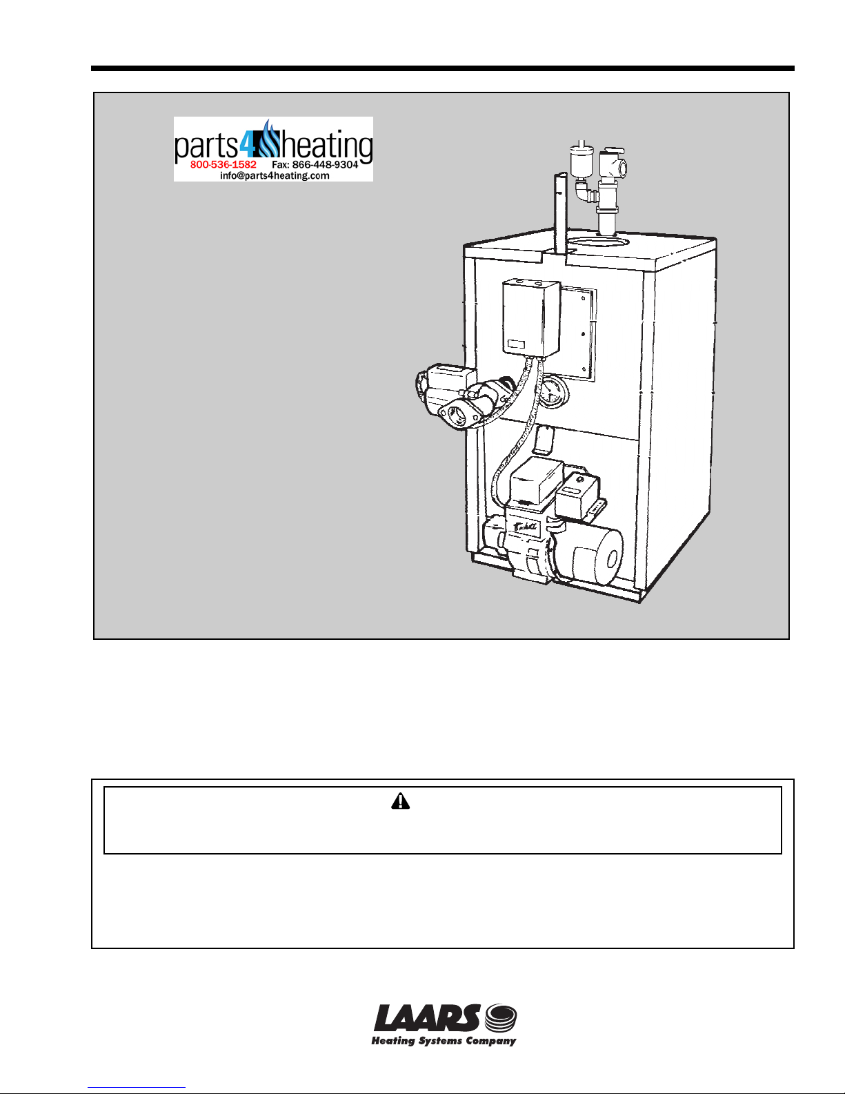
Newport
Oil Fired Boiler
FOR YOUR SAFETY: This product must be installed and serviced by a professional service technician,
qualified in boiler installation and maintenance. Improper installation and/or operation could create
carbon monoxide gas in flue gases which could cause serious injury, property damage, or death.
Improper installation and/or operation will void the warranty.
WARNING
If the information in this manual is not followed exactly, a fire or explosion may result
causing property damage, personal injury or loss of life.
Do not store or use gasoline or other flammable vapors and liquids in the vicinity of this or
any other appliance.
Installation and service must be performed by a qualified installer, service agency, or fuel oil
supplier.
52-206B
A subsidiary of BRADFORD WHITE Corporation

Page 2
LAARS HEATING SYSTEMS
TABLE OF CONTENTS
SECTION 1.
General Information
1A. Boiler Installation .......................................... 3
1B. Freight Claims .............................................. 3
1C. Boiler Location .............................................. 3
1D. Boiler Clearances (to combustibles) ............. 3
1E. Floor ............................................................. 3
1F. Combustion and Ventilation Air ..................... 3
1G. Chimney and Draft Requirements ................. 3
1H. Jacket (normally fitted) .................................. 3
1I. Oil Burner (normally fitted) ............................ 3
1J. Boiler Controls (normally fitted) ..................... 3
1K. Oil ................................................................. 3
1L. Oil Storage and Pipe Layout ......................... 3
1M. Electrical Wiring............................................ 4
1N. Operation
(Honeywell L.8124A aquastat relay) ............. 4
1O. Domestic Water Piping ................................. 4
1P. Cleaning the Boiler ....................................... 4
1Q. Cleaning the Chimney................................... 4
1R. Servicing the Burner ..................................... 5
1S. Maintenance of the Tankless Coil ................. 5
SECTION 2.
Part Numbers
................................................................... 11
Trianco Newport
Page 3
SECTION 1.
General Information
These boilers have been designed and
constructed according to ASME codes using heavy
gauge steel tubes and boiler plate.
The reliable heat exchanger incorporates special
flue baffles to assure quiet and efficient operation and
a purpose designed ceraform combustion chamber
minimizes base loss and also provides a tight
enclosure with the heat exchanger.
The domestic hot water coil is located at the top
of the boiler in the hottest zone for an ample supply of
hot water and a unique feature of its attachment is the
raised coil flange which allows the use of clamping
bolts rather than studs, thereby eliminating water leaks
caused by broken studs.
The complete unit comes pre-assembled for easy
installation and is encased by a fully insulated baked
enamel jacket.
1A. Boiler Installation
For recommended installation practice reference
should be made to the National Fire Protection
Standard for Oil Burning Equipment (NFPA 31 Latest Edition).
1B. Freight Claims
Inspection should be made of boiler and its
components for damage upon arrival. Any claims for
damage should immediately be filed against the
carrier by the consignee.
1C. Boiler Location
The boiler should be positioned as near to the
chimney as possible and have a minimum smoke pipe
connector length of 18"(457mm).
Caution
Newport boilers must not be directly connected to a
heating system using oxygen permeable tubing (see
warranty). Use a water to water heat exchanger
between boiler and system to prevent corrosion.
1F. Combustion and Ventilation Air
To insure an adequate supply of fresh air for
combustion and ventilation an inlet and outlet opening
should be provided at floor and ceiling level. Each
opening must have a minimum of one square inch
(16.5 sq. cm) of free area for every 1,000 BTU/h
(293kW) of input or 140 square inches (903 sq. cm)
per one gallon (3.785L) of oil burned per hour. The
openings must not be in a position liable to blockage.
1G. Chimney and Draft Requirements
To assure the safe and proper operation of the oil
burner the boiler must be connected to a chimney
having sufficient draft at all times to evacuate the flue
gases to atmosphere. A draft regulator must be
installed in the smoke-pipe as near to the flue as
possible and adjusted to achieve an overfire draft of
0.01 ins. W.C.
1H. Jacket (normally fitted)
If not fitted, assemble panels in accordance with
instructions in Figure 4.
1I. Oil Burner (normally fitted)
If not fitted, insert burner tube into boiler so that
it is approximately ¼" (6mm) from inside wall of
ceraform chamber, then clamp mounting flange and
bolt up to front-plate (see Figure 3).
The burner should be wired and connected to the
oil line in accordance with the manufacturer’s
instructions.
1J. Boiler Controls (normally fitted)
If controls are supplied separately, fit them to the
boiler in the positions shown in Figure 3, with jacket
in place.
Circulator - 1¼" return tapping at front of boiler.
Tridicator - temp/press. gauge.
Relief Valve - Provide ¾" tee and auto vent as
shown on front page for air elimination.
Aquastat Relay - L8124A - ¾" tapping in coil
plate.
Fit a drain valve (not supplied) in a tee at
hydronic return connection and check all connections
are made water tight.
1D. Boiler Clearances (to combustibles)
Top - 6" (152mm) Front - 24" (610mm)
Rear - 6" (152mm) Sides - 6" (152mm)
1E. Floor
The boiler must be mounted on a
noncombustible masonry or cement floor with no
combustibles underneath.
1K. Oil
USE ONLY No. 2 HEATING OIL. Do not use
gasoline, crankcase draining or any oil containing
gasoline.
1L. Oil Storage and Pipe Layout
Storage Tank: Consult local fire and building
codes for acceptable fuel storage methods in your area.
Fuel Line: A single pipe system of not less than
3/8" OD copper tubing is recommended when fuel
Page 4
LAARS HEATING SYSTEMS
storage level is not below the fuel unit. A two pipe
system of not less than 3/8" OD copper tubing is
recommended when lowest fuel level is below but not
more than 8 feet below fuel unit.
Important: Refer to burner (pump) instructions
for detailed fuel line and pump usage information. All
installations must conform to local and national codes.
See Figures 5A and 5B.
Figure 5A One-pipe system - pipe and tank layout.
Figure 5B Two-pipe system - pipe and tank layout.
1M. Electrical Wiring
All wiring must comply with the National
Electrical Code, NFPA 70, local codes and ordinances
regarding wire size, type of insulation and enclosures
etc. (see Figure 6).
1N. Operation
(Honeywell L8124A aquastat relay)
A call for heat from the room thermostat causes
the relay to “make “ the burner circuit and also feed
the circulator provided the boiler water temperature is
above the low limit setting (usually 190°F [88°C] to
210°F [99°C]). The burner and circulator then
continue to run until the room thermostat is satisfied.
A high limit switch shuts off burner in the event
of water temperature exceeding the high limit setting,
usually 20°F (-7°C) to 30°F (-1°C) above the low limit
setting.
The low limit switch and circulator maintain
boiler water temperature for domestic hot water
services and prevents circulation of heating system
water if domestic water is not hot enough.
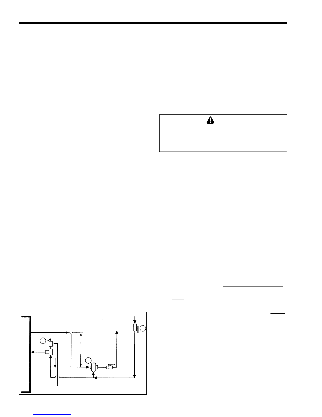
1O. Domestic Water Piping
1. Connect anti scald tempering valve (12) “HOT”
port to hot water outlet from unit. This valve
should be mounted 3" (76mm) to 6" (152mm)
below the outlet and set for 120° F mixed
delivery temperature or as local codes dictate
(see Figure 1).
13
B
O
I
L
E
11
3 - 6"
(76mm - 152mm)
12
R
Figure 1. Domestic water piping.
2. Connect gate or shutoff valve (13) to anti scald
tempering valve (12) “MIX” port, and another to
the cold water inlet.
3. Connect pressure relief valve (11) (if required
by codes), maximum 150 PSI as close to the unit
as possible. No other valves or restrictions may
be installed between the DHW coil and the
relief valve.
(DO NOT USE A TEMPERATURE/
PRESSURE RELIEF VALVE AS THIS IS NOT A
STORAGE HOT WATER HEATER).
WARNING
Flue gases are dangerous - do not operate boiler if
there is an escape of flue gas. Call a qualified
serviceman and have the entire flue and venting
system inspected.
1P. Cleaning the Boiler
To maintain the high thermal efficiency and a
long life from your boiler, it should be cleaned at least
once a year, preferably at the end of the heating
season. This is particularly important as rusting can
occur when the boiler is idle.
It is recommended that a service contract be
arranged with a properly equipped serviceman who
will be able to do the job efficiently and without mess.
1. Switch off electrical supply to the boiler.
2. Remove smoke-pipe from boiler.
3. Remove top jacket panel.
4. Unscrew the securing nuts and remove flue
collector.
5. Remove baffles from flue tubes.
6. Remove burner by unscrewing the flange
mounting nuts.
7. Remove soot and scale deposits from tubes with
a flexible wire brush,
taking care not to damage
“ceraform” combustion chamber, below outer
tubes.
8. Vacuum out accumulated deposits from
combustion chamber through burner port,
taking
care not to damage “ceraform” combustion
chamber, below outer tubes.
9. Replace all parts, ensuring flue-baffles are
correctly located. Ensure flue collector and
smoke-pipe are tightly sealed.
1Q. Cleaning the Chimney
Sweep all soot deposits from chimney and
smoke-pipe once a year, preferably at the end of the
heating season. It is also advisable to inspect the
chimney and smoke-pipe at the beginning of heating
season as birds may have built their nest inside or
other material may be causing a blockage.
 Loading...