

Page 1
Mini-Therm JVi Venting Material 10-27 December 14, 2010
To: Manufacturer’s Representatives, Distributors, Contract Service Centers, Regional Sales Managers
and Internal Departments
From: Tom Gervais, International Sales Director
There has been an instance of confusion regarding suitable venting material for use on the Mini-Therm JVi
product with
in Canada. Therefore, the table used in section “1H-2: Horizontal Venting – Category III” of the
Mini-Them manual has been updated to more clearly indicate what is an allowable vent material.
In Canada: Use "BH-Type" vent materials certified to ULC-S636 Class I (more than 135°C, but not more
than 245°C flue gas temperature), made of AL29-4C stainless steel or equal.
'RQRWXVHSODVWLFYHQWLQJRIDQ\NLQG
Addendum to Mini-Therm JVi Manual
This Addendum applies to the following Documents:
Models Affected Sizes Part No. Doc. No.
Mini-Therm JVi, JVH 50-225 H2020900D Doc. 1080D
Page 8 Change to Column 2 Table:
Materials Vent Length
1H-2. Horizontal Venting - Category III
(a) Vent Connections
In U.S.A.: UL type 304, 316 or 294-C Up to a maximum
stainless steel, 26 gauge minimum. of 55' (17m) of
In Canada: Use "BH-Type" vent equivalent pipe
materials certified to ULC-S636 run (including
Class I (more than 135°C, but not required elbows).
more than 245°C flue gas
temperature), made of AL29-4C
stainless steel or equal.
Do not use plastic venting of any kind.
800.900.9276 • Fax 800.559.1583 (Customer Service, Service Ad viso rs)
20 INDUSTRIAL WAY, ROCHESTER, NH 03867 • 603.335.6300 • Fax 603.335.3355 (Technical Support)
1869 SISMET ROAD, MISSISSAUGA, ONTARIO, CANADA L4W 1W8 • 905.238.0100 • Fax 905.366.0130
Page 2
Installation and Operation Instructions Document 1080D
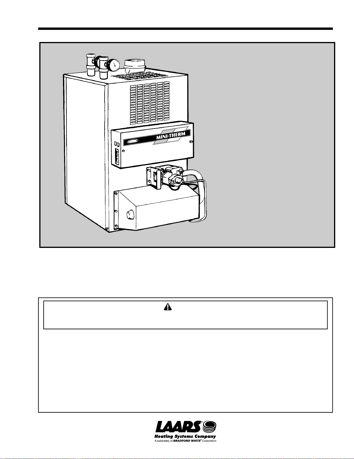
Installation and
Operation
Instructions for
Mini-Therm JVi
Induced Draft
Residential
Gas-Fired
Hydronic Boilers
Model JVH
These instructions are to be stored next to the boiler for reference purposes.
FOR YOUR SAFETY: This product must be installed and serviced by a professional service technician,
qualified in hydronic boiler installation and maintenance. Improper installation and/or operation could
create carbon monoxide gas in flue gases which could cause serious injury, property damage, or death.
Improper installation and/or operation will void the warranty.
WARNING
If the information in this manual is not followed exactly, a fire or explosion may result
causing property damage, personal injury or loss of life.
Do not store or use gasoline or other flammable vapors and liquids in the vicinity of this or
any other appliance.
WHAT TO DO IF YOU SMELL GAS
• Do not try to light any appliance.
• Do not touch any electrical switch; do not use any phone in your building.
• Immediately call your gas supplier from a nearby phone. Follow the gas supplier's
instructions.
• If you cannot reach your gas supplier, call the fire department.
Installation and service must be performed by a qualified installer, service agency, or gas
supplier.
H2020900D
Page 3

Page 2
LAARS Heating Systems
TABLE OF CONTENTS
SECTION 1.
General Information
1A. Introduction................................................... 3
1B. Warranty.......................................................3
1C. Heater Identification......................................3
1D. Flow Requirements.......................................3
1E. Boiler Placement ..........................................4
1F. Gas Supply and Piping .................................4
1G. Combustion Air Supply .................................5
1H. Venting .........................................................6
1H-1. Vertical Venting - Category I .........................7
1H-2. Horizontal Venting - Category III ...................8
1H-3. Common Venting System ............................. 9
1I. Water Piping of Boiler System ....................10
1I-1. By-Pass Piping ........................................... 10
1J. Chilled Water Systems ............................... 10
1K. Electrical Wiring .......................................... 12
1L. Filling the System ....................................... 12
SECTION 2.
Operating Procedures
2A. System Start-up ..........................................13
2B. Sequence of Operation ............................... 15
SECTION 3.
3A. Maintenance ...............................................17
3B. Electrical Troubleshooting .......................... 18
Page 4
Mini-Therm JVi
Page 3
SECTION 1.
General Information
WARNING
The JVi induced draft hydronic boiler must be
installed in accordance with the procedures detailed
in this manual, or the Laars warranty will be voided.
The installation must conform to the requirements of
the local jurisdiction having authority, and, in the
United States, to the latest edition of the National
Fuel Gas Code, ANSI Z223.1. In Canada, the
installation must conform with the latest edition of
CAN/CGA B149.1 OR .2 installation codes for gas
burning appliances, and/or local codes.
Any modifications to the boiler, its gas controls, gas
orifices, wiring or draft inducer assembly may void
the warranty. If field conditions require
modifications, consult the factory representative
before initiating such modifications.
1A. Introduction
This manual provides information necessary for
the installation, operation, and maintenance of the
Laars Model JVi induced draft, low pressure, copper
tube hydronic boilers. These boilers are available in
two configurations; the JVH has a hot surface pilot
ignition system and the JVP has an electronic
intermittent ignition device (I.I.D.). Look for the
model designation on the rating plate, which can be
found on top of the boiler.
All application and installation procedures
should be reviewed completely before proceeding
with the installation. Consult the Laars factory, or
local factory representative, with any problems or
questions regarding this equipment. Experience has
shown that most operating problems are caused by
improper installation.
1B. Warranty
The Laars Model JVi induced draft boilers are
covered by a limited warranty. A copy of the warranty
is printed on the back cover of this manual. The owner
should fill out the warranty registration card and
return it to Laars.
All warranty claims must be made to an
authorized Laars representative or directly to the
factory. Claims must include the boiler serial number
and model (this information can be found on the
rating plate), installation date and name of the
installer. Shipping costs are not included in the
warranty coverage. Some accessory items are shipped
in separate packages. Verify receipt of all packages
listed on the packing slip. Inspect each item for
damage immediately upon delivery, and advise the
carrier of any shortages or damage. Any such claims
should be filed with the carrier. The carrier, not the
shipper, is responsible for shortages and damage to
the shipment whether visible or concealed .
1C. Heater Identification
Consult the rating plate on the boiler. The
following example simplifies the heater identification:
123456
JV H 125 N C S
Table 1. Heater Identification.
1. Basic boiler series model
2. Ignition system: (H) Hot surface pilot ignition
3. Input rate X 1000 BTU/Hr
4. Gas Type: (N) Natural (P) Propane
5. Firing rate: (C) On/off, induced draft
6. Options: (S) Standard, (P) with Pump,
(A) Extra Aquastat
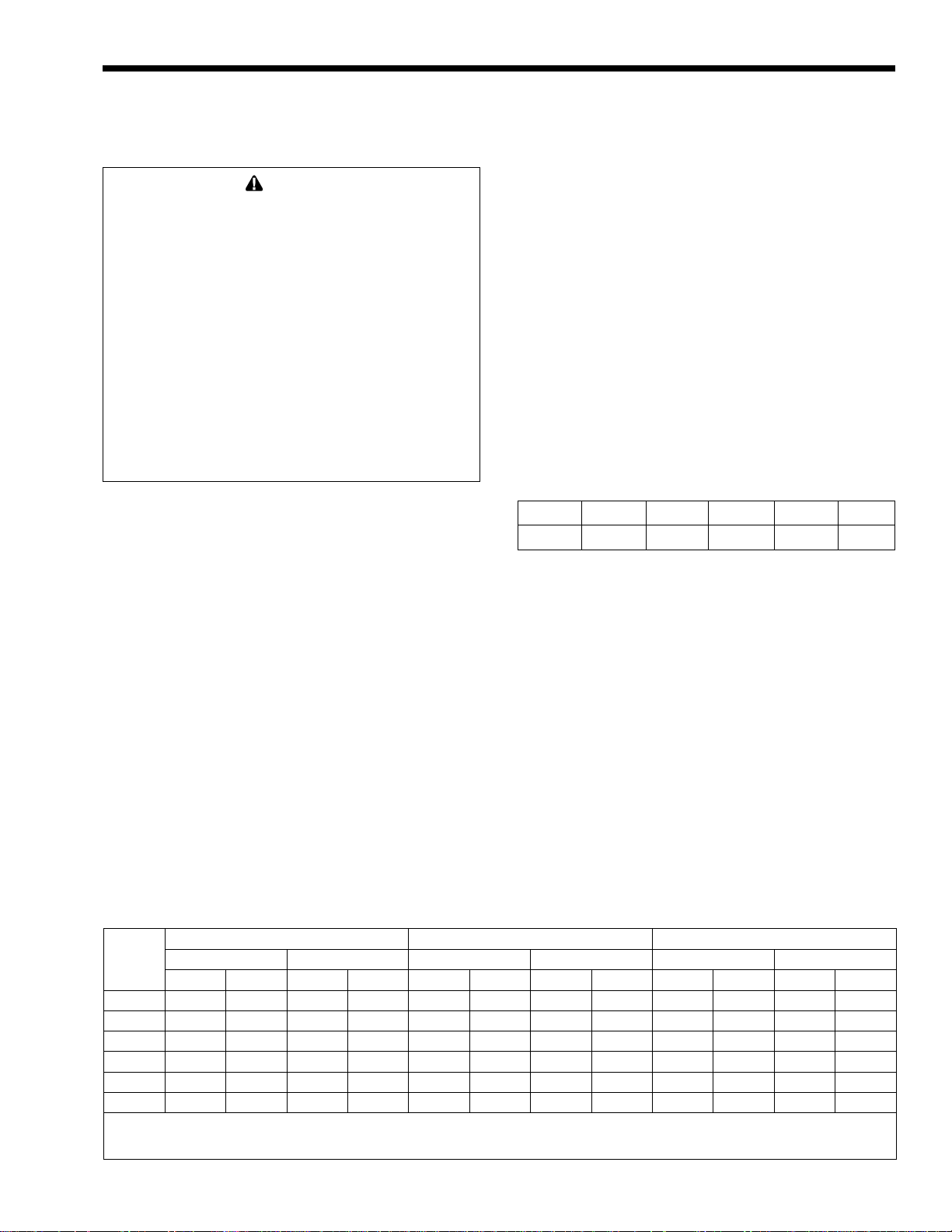
1D. Flow Requirements
All high recovery, low volume water boilers
must have adequate flow for proper operation. Pump
selection is critical to this goal, and pumps should be
selected to provide for correct system design water
temperature rise. Table 2 details temperature rise and
water flow for the Mini-Therm boilers.
8°C
15°F
Size
50 5.3 0.3 0.3 0.1 4.0 0.3 0.2 0.1 3.2 0.2 0.1 0.0
75 8.0 0.5 0.6 0.2 6.0 0.4 0.3 0.1 4.8 0.3 0.2 0.1
100 10.7 0.7 1.3 0.4 8.0 0.5 0.7 0.2 6.4 0.4 0.5 0.2
125 13.3 0.8 2.2 0.7 10.0 0.6 1.3 0.4 8.0 0.5 0.8 0.2
160 17.0 1.1 2.5 0.8 12.8 0.8 1.8 0.5 10.2 0.6 1.2 0.4
225 24.0 1.5 5.0 1.5 18.0 1.1 3.1 0.9 14.4 0.9 1.9 0.6
ft = Pressure drop (headloss) through the boiler in feet of water. m = Pressure drop (headloss) through the boiler in meters of water.
Flow Rate Headloss Flow Rate Headloss Flow Rate Headloss
gpm l/s ft m gpm l/s ft m gpm l/s ft m
gpm = Water Flow in gallons per minute. l/s = Water flow in liters per second.
Note: Shaded area is the recommended flow and temperature rise.
Table 2. Temperature Rise (degrees °F, degrees °C).
20°F
11°C
25°F
14°C
Page 5
Page 4
LAARS Heating Systems
Damage from improper flow is not warranted.
Failure to insure proper water flow through the
heat exchanger of the boiler will void the Laars
warranty. Flow can be verified by measuring the
difference in water temperatures between the boiler
inlet (system return) and outlet (system supply). For
example: For a JV-100 installation, the inlet water
temperature is 160°F (71ºC), and the outlet temperature is 180°F (82ºC). That means there is a 20ºF
(11ºC) temperature rise through the boiler. According
to Table 2, that would indicate a flow rate of 8 gpm
(0.5 l/s). Temperature rise must be measured with the
longest (highest head) zone calling for heat alone.
Other factors to be considered before selecting a
pump are pipe size, the number and type of fittings
throughout the system, smoothness of the interior
surface of the pipe, the quantity of water flowing
through the pipe, whether a glycol solution (for freeze
protection) is being used, and the total length of
piping in the system. Table 3 can help in proper pump
selection.
1/2" Pipe 3/4" Pipe 1" Pipe 1-1/4" Pipe
Size
Pump
H.P.
1/25 1/12 1/25 1/12 1/6 1/25 1/12 1/6 1/25 1/12 1/6
50 50 99 390 680 * * * * * * *
75 * 35 160 300 460 640 * * * * *
100 * * 77 150 260 330 620 * * * *
125 * * 27 80 140 170 360 600 * * *
160 * * * 25 72 57 160 330 190 480 *
225 * * * * * * * 110 * 69 330
*A circular and/or primary/secondary piping are required. Consult factory.
1. Chart is based on 30°F (17°C) maximum temperature rise.
2. Calculations are based on Type L copper tubing with one zone valve and
eight elbows.
3. Typical circulating pumps: 1/25 HP=Taco 007, B&G LR-20 or SLC-25,
Grundfos UP15-42F, or equivalent. 1/2 HP=B&G LR-12, Grudnfos
U26-42F, or equivalent. 1/6 HP=B&G series HV, Grundfo UP43-75,
or equivalent.
Table 3. Maximum Suggested Circuit Length in Feet.
Pump H.P. Pump H.P. Pump H.P.
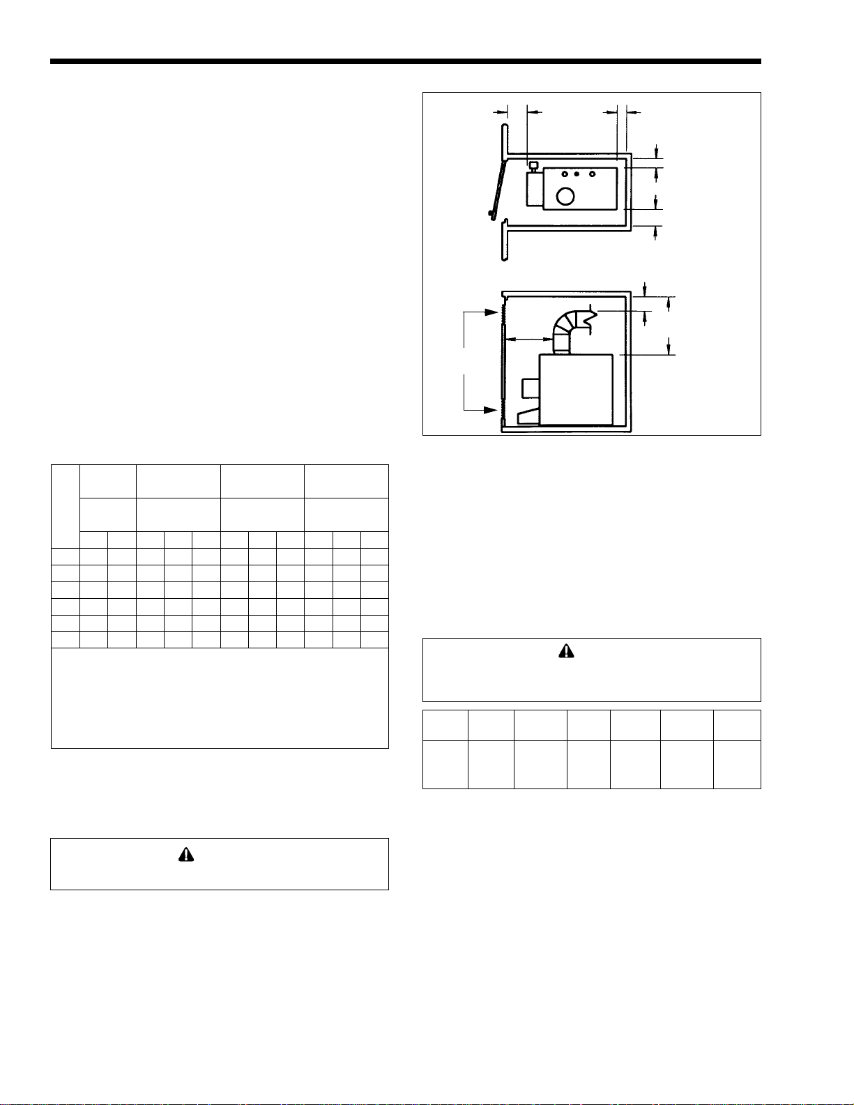
1E. Boiler Placement
WARNING
This boiler is intended for indoor installation only.
1. The boiler must be placed to provide clearances
on all sides for maintenance and inspection.
There must also be minimum distances
maintained from combustible surfaces. Avoid
locations which can be damaged by water or
moisture.
2. A minimum of 15" (381mm) access must be
available in front of the boiler for burner tray
removal. Consult local codes for clearances to
hot water pipes and accessories.
4
(102)
6
(152)
Air
Openings
Figure 1. Closet Installation.
MIN
2
(51)
6
(152)
2
(51)
5
(127)
23
(584)
TOP
VIEW
SIDE
VIEW
Dimensions in
inches (mm).
3. If the boiler is to be installed in a garage, all
burners and burner ignition devices must have a
minimum 18" (457mm) clearance above the floor.
4. The Model JVi-50 through JVi-225 boilers can
be installed in a closet as long as the minimum
clearances shown in Table 4 are observed.
Special attention should be paid to clearances
between the front of the boiler and the closet
door when it is closed (see Figure 1).
Caution
Do not install this boiler in a location subject to
negative pressure, or improper operation will occur.
Boiler
Sizes:
50 to
225
*1" (25mm) clearance using Type B double wall vent pipe.
Left Right
Side Side
2" 5" 2" 4" 6" 23"
51mm 127mm 51mm 102mm 152mm 584mm
Table 4. Minimum Boiler Clearances
From Combustible Surfaces.
Rear Front Flue* Top
5. All boilers are designed and certified for
installation on a combustible floor. Ensure that the
boiler is level from all sides. NEVER store objects on
or around the boiler. Boilers must NEVER be
installed on carpeting.
1F. Gas Supply and Piping
Review the following instructions before
proceeding with the installation.
1. Verify that the boiler is fitted for the proper type
of gas by checking the rating plate. Laars boilers
Page 6
Mini-Therm JVi
Page 5
are normally equipped to operate below a 2000'
(610m) altitude. Boilers equipped to operate at
higher altitudes have appropriate stickers or tags
attached next to the rating plate.
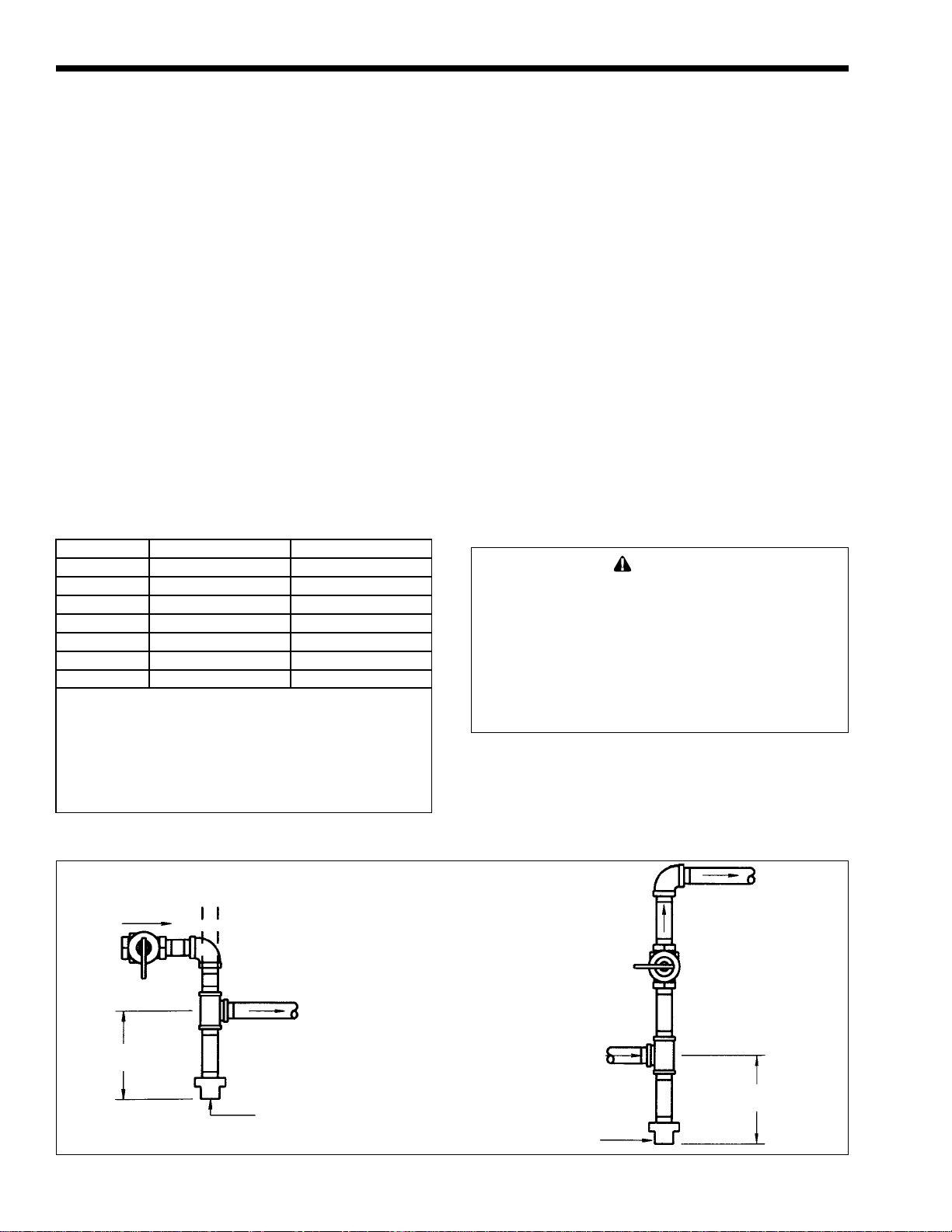
2. Use the figures in Table 5 to provide adequate
gas piping from the gas meter to the boiler.
3. A trap (drip leg) must be provided ahead of the
gas controls (see Figure 3). A manual gas shutoff
valve approximately 5' (1.5m) above the floor
must also be provided for service, convenience
and safety. Check the local codes.
4. Disconnect the boiler from the gas supply pipe
before pressure testing the pipe for gas leaks.
5. Provide gas supply pressure to the boiler per
Table 6. The regulator is pre-set at the factory,
and normally requires no further adjustment.
NOTE : The boiler and all other gas appliances
sharing the boiler gas supply line must be firing at
maximum capacity to properly measure the inlet
supply pressure. Low gas pressure could be an
indication of an undersized gas meter and/or
obstructed gas supply line.
Distance
From
Gas
Meter in
Feet (m)
0-50'
(0-15)
50-100'
(15-30)
100-200'
(30-60)
NOTE: These figures are for Natural Gas (.65 Sp. Gr.), and are based
on 1/2" water column pressure drop. Check supply pressure with a
manometer, and local code requirements for variations. For LPG,
reduce pipe diameter one size, but maintain a 1/2" minimum diameter.
A 'normal' number of Tees and elbows have been taken into allowance.
50 75 100 125 160 225
1/2 3/4 3/4 3/4 1 1
3/4 3/4 3/4 1 1 1-1/4
3/4 1 1 1 1-1/4 1-1/4
Boiler Size
Inches
Table 5. Gas Piping Sizes.
Gas Pressure
Minimum Supply
Pressure
Maximum Supply
Pressure
Manifold Gas
Pressure
Natural Gas Propane (LP)
in. W.C. kPa in. W.C. kPa
5.5 1.4 10 2.5
9 2.2 14 3.4
4 1 9 2.2
Table 6. Gas Pressure Measurement.
6. Before operating the boiler, the complete gas
supply system and all connections must be tested
for leaks using a soap solution.
1G. Combustion Air Supply
The boiler location must provide sufficient air
supply for proper combustion, and ventilation of the
surrounding area as outlined in the latest edition of
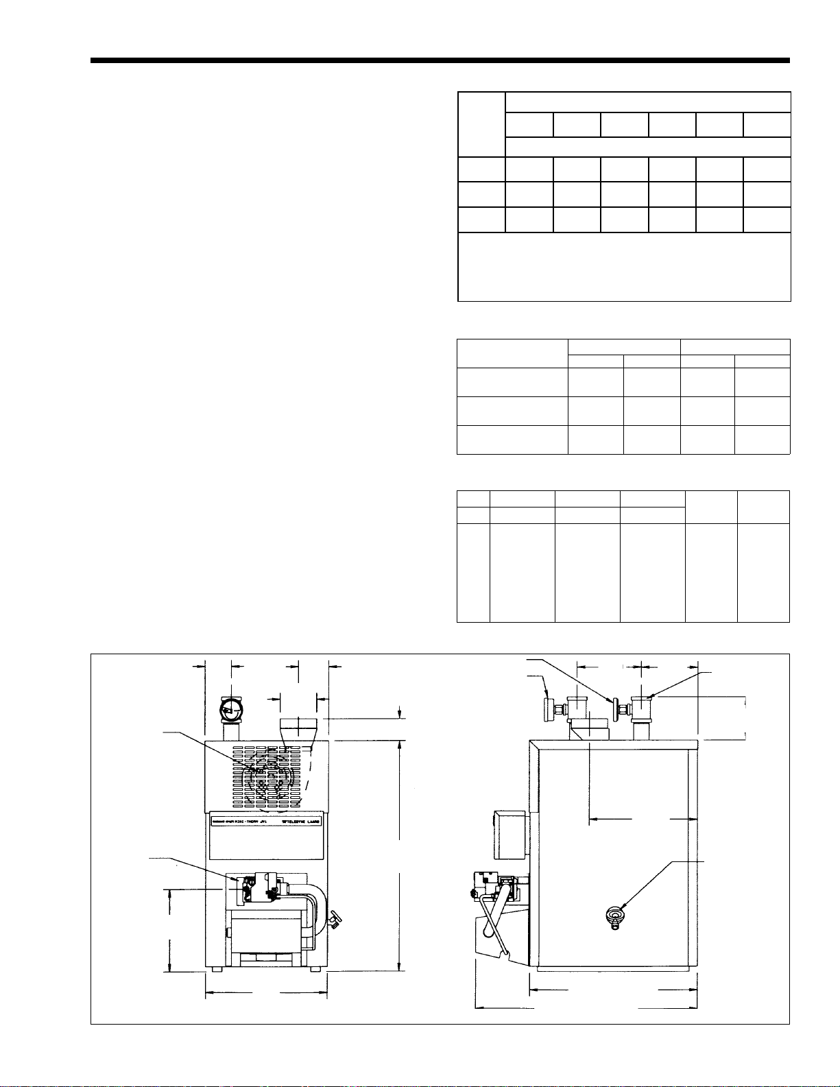
TEMPERATURE GAUGE
2.4
(6.1)
25
(635)
REF
INDUCED
DRAFT
BLOWER/
MOTOR
PULL-OUT
GAS
MANIFOLD
BURNER
TRAY
C
4
(102)
DIA.
B
Size A B C
mm
50
75
100
125
160
225
in.
13-3/8
13-3/8
16-7/8
16-7/8
20-3/8
25-5/8
340
340
429
429
518
651
in.
3-1/8
2-1/4
5-3/4
5-1/2
7-1/4
10
Table 7. JVi Dimensions.
TEMP./PRESSURE
GAUGE
mm
79
57
146
140
184
254
(178)
Water
Connection
mm
in.
73
2-7/8
2
2-7/8
2
2
2
7
11.8
(298)
51
73
51
51
51
6
(152)
1-1/4
1-1/4
1-1/4
1-1/4
1-1/4
1-1/4
1-1/4" NPT TEE
2X
DRAIN
Gas
Connection
1/2
1/2
1/2
1/2
1/2
3/4
4.9
(124)
8.9
(226)
A
Figure 2. Dimension Information.
Dimensions in
inches (mm).
18 (457) REF.
24 (610)
REF.
Page 7
Page 6
LAARS Heating Systems
U.S. ANSI standard Z223.1 or in Canada, CAN/CGAB149.1 or .2, and any local codes that may be
applicable.
In general, these requirements specify that the
boiler rooms which represent confined spaces should
be provided with two permanent air supply openings;
one within 12 inches (305mm) of the ceiling, the other
within 12 inches (305mm) of the floor.
Outside Air Supply: When combustion air is
supplied directly through an outside wall, each
opening should have a minimum free area of one
square inch per 4,000 BTU/h (6 sq. cm per 1.2 kW)
input of the total input rating of all appliances in the
enclosed area.
Inside Air Supply: When combustion is
supplied from inside the building, each opening
should have a minimum free area of one square inch
per 1,000 BTU/h (6 sq. cm per 0.3 kW) input of the
total input rating of all appliances in the enclosed
area. These openings should never be less than 100
square inches (645 sq. cm).
NOTE: In Canada, follow Canadian Standard,
CAN/CGA-B149 or local codes.
Boiler Size Outside Air Area Inside Air Area
sq. in
50
75
100
125
160
225
*Area indicated is for one of two openings: one at floor level
and one at the ceiling, so the total net free area would be
double the figures shown. For special conditions, refer to
NFPA54 ANSI Z223.1. In Canada, refer to the National
Standard CAN1-B149.1 or .2, which differs from this table.
NOTE: Check with louver manufacturers for Net Free Area of
Louvers. Correct for screen resistance to the Net Free Area if a
screen is used.
15
20
25
32
40
60
Table 8. Minimum Recommended
Air Supply to Boiler Room.
sq. cm
97
129
161
206
258
387
sq. in.
100
100
100
125
160
225
sq. cm
645
645
645
807
1032
1452
Exhaust Fans or Vents: Any equipment which
exhausts air from the boiler room can deplete the
combustion air supply or reverse the natural draft
action of venting system. This could cause flue
products to accumulate in the boiler room. Additional
air must be supplied to compensate for such exhaust.
The information in Table 8 is not applicable in
installations where exhaust fans or blowers of any
type are used. Such installations must be designed by
qualified engineers.
If a blower or fan is used to supply air to the
boiler room, the installer should make sure it does not
create drafts which could cause nuisance shutdowns. If
a blower is necessary to provide adequate combustion
air to the boiler, a suitable switch or equivalent must
be wired into the boiler control circuit to prevent the
boiler from firing unless the blower is operating.
The boiler must be completely isolated and
protected from any source of corrosive chemical
fumes such as those emitted by trichloroethylene,
perchloroethylene, chlorine, etc.
1H. Venting
WARNING
This boiler must be vented in accordance with Part
7, Venting of Equipment, of the latest edition of the
National Fuel Gas code, ANSI Z223.1 and all
applicable local building codes. In Canada, follow
CAN/CGA B149 Installation codes. Improper venting
of this appliance can result in excessive levels of
carbon monoxide which can result in severe
personal injury or death!
The boiler vent collar must be fastened directly
to an unobstructed vent pipe of the same diameter
with rustproof sheet metal screws no longer than 1/2"
(13mm) and located to prevent interference with the
inducer damper.
DROP
HORIZONTAL
3" (76mm)
MIN.
Figure 3. Gas Supply Piping.
TO BOILER
SEDIMENT TRAP
OR DRIP LEG
SEDIMENT TRAP
OR DRIP LEG
TO BOILER
RISER
3" (76mm)
MIN.
Page 8
Mini-Therm JVi
Page 7
Do not weld the vent pipe to the boiler collar.
The weight of the stack must not rest on the boiler.
The boiler top must be easily removable for normal
boiler service and inspection.
Avoid terminating boiler vents near air
conditioning or air supply fans. The fans can pick up
exhaust flue products from the boiler and return them
to the building, creating a possible health hazard.
Avoid oversized vent pipe or extremely long
runs of the pipe, which may cause excessive cooling
and condensation.
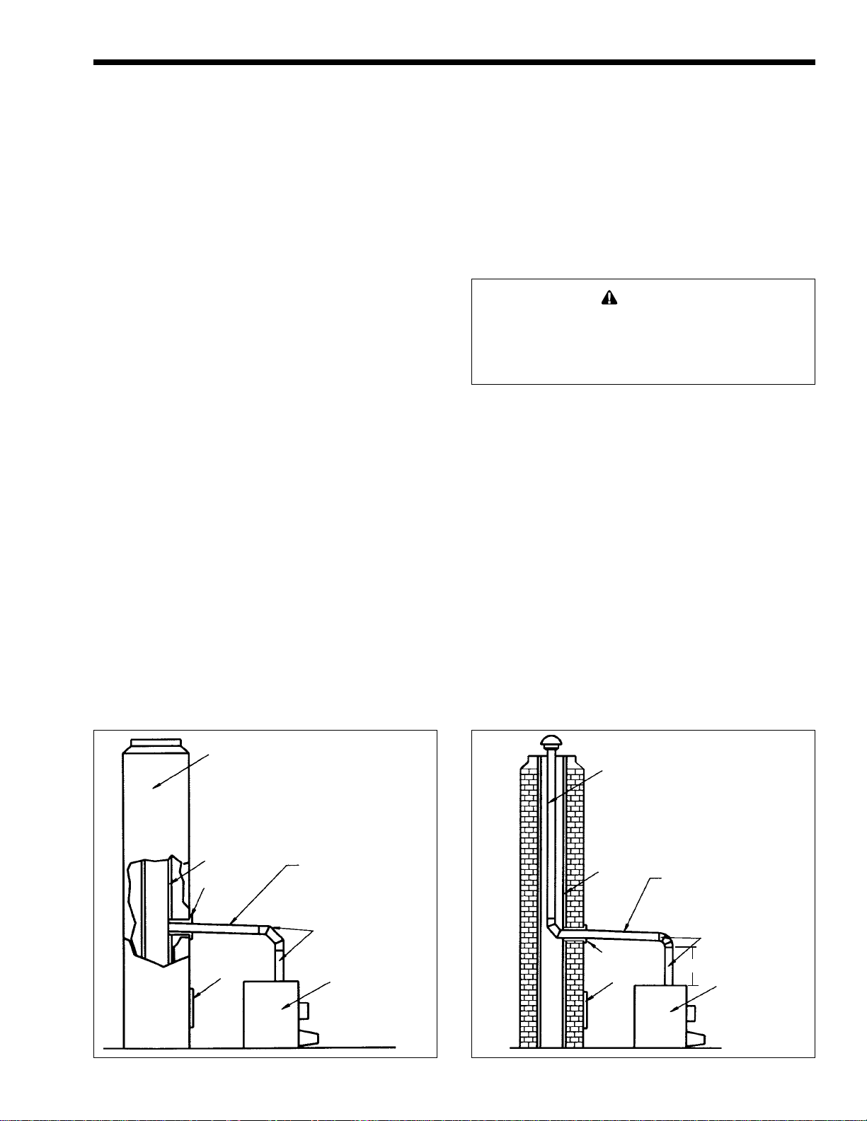
1H-1. Vertical Venting - Category I
The Mini-Therm JVi series boiler can be vented
into a masonry chimney, (see Figure 4) provided
several conditions are met:
1. The chimney must have an appropriate tile lining
that is clean, properly constructed and properly
sized.
2. The chimney passage way shall be examined to
ascertain that it is clear and free of obstructions.
3. If a chimney rebuild is required, it shall conform
to nationally recognized standards (see National
Building Code or ANSI/NFPA 211).
4. The boiler must not be connected to a fireplace,
wood stove or other solid fuel burning
equipment.
5. When the boiler and a hot water heater are to be
connected to the same chimney, they must have
their own vent connector and enter the chimney
at least 6" (152mm) apart.
(a) Vent Connections
Use type B double wall or type C single wall (26
gauge, minimum thickness), gas vent pipe from the
boiler to the chimney. Installation of a riser, with a
minimum 12" (305mm) height above the boiler, is
recommended. The vent system should be sloped up
toward the chimney 1/4" per foot (20mm per meter).
The vent connector must be supported for the design
and weight of the material employed, to maintain
clearances and prevent physical damage and
separation of joints.
IMPORTANT NOTE: Always provide a
minimum clearance of 6" (152mm) between Type C
(single wall) vent pipe and any combustible materials.
WARNING
Single wall vent pipe must NEVER pass through
interior walls or through floors or ceilings! Failure to
comply with this warning could result in a fire
causing property damage, personal injury, or death!
When installing the vent system all applicable
national and local codes must be followed! The use of
thimbles, firestops and other protective devices, when
penetrating combustible or noncombustible
construction, must be in accordance with all
applicable national and local codes.
Vertical vents of the induced draft JVi boilers
must be installed in accordance with the code
requirement for Category 1, Fan Assisted Appliances.
Follow the requirements as indicated in the latest
edition of ANSI Z223.1/NFPA 54, sizing of Category
I Venting System and Appendix G, or in Canada,
follow the instruction of CAN/CGA-B149 installation
code.
An unused lined chimney can be used as a
raceway for single wall vent pipe, (see Figure 5).
Never run vent pipe through a flue that has another
appliance attached to it.
CHIMNEY
LINER
THIMBLE
CLEANOUT
Figure 4. Chimney Venting. Figure 5. Vertical Venting.
1/4"
PER FT.
(20mm PER M)
SLOPE
VENT
SYSTEM
BOILER
CHIMNEY
LINER
THIMBLE
CLEANOUT
1/4"
PER FT.
(20mm PER M)
SLOPE
VENT
SYSTEM
12" (305mm)
BOILER
Page 9

Page 8
10 (3.0) OR
LESS
LAARS Heating Systems
MORE THAN 10
(3.0)
2 (0.6) MIN.
WALL OR
PARAPET
CHIMNEY
10 (3.0)
OR LESS
2 (0.6)
RIDGE
Figure 6. Vertical Vent Termination.
MIN.
CHIMNEY
3 (0.9)
MIN.
TERMINATION
10 FT. (3.0m)
OR LESS FROM RIDGE,
WALL OR PARAPET
3 (0.9)
MIN.
Dimensions in feet (m).
(b) Vent Termination
A listed vent terminal designed for the type of
pipe being used must complete the vertical run where
it exits the chimney. The vent pipe must extend at
least 3' (.9m) above the highest point where it passed
through the roof. In addition, the vent cap must be at
least 2' (.6m) higher than any portion of a building
within a horizontal distance of 10' (3m). Clearance to
any combustible materials must be maintained as
listed (see Figure 6).
3 (0.9)
MIN.
WALL OR
PARAPET
NOTE: NO HEIGHT
ABOVE PARAPET
REQUIRED WHEN
FROM WALLS OR
PARAPET IS MORE
THAN 10 FT. (3.0m)
CHIMNEY
RIDGE
MORE THAN 10
(3.0)
2 (0.6)
MIN.
CHIMNEY
10 (3.0)
3 (0.9)
MIN.
For best results, horizontal vent systems should
be as short and straight as possible. Material of vent
connectors shall be as follows:
Materials Vent Length
In U.S.A.: UL type 304, 316 Up to a maximum of 55' (17m)
or 294-C stainless steel, of equivalent pipe run
26 gauge minimum. (including required elbows).
In Canada: Use “BH” vent
type complying with ULC
S-636 Standard.
1H-2. Horizontal Venting - Category III
When venting is horizontal, or cannot meet the
requirements of Category I, it can develop positive
pressure and must be installed in accordance with this
section and the specific vent manufacturer’s
instructions.
Description Manufacturer Product
High Temperature
RTV
2" (51mm) wide
Aluminum foil tape
- adhesively backed
2" (51mm) wide
Aluminum foil tape
- adhesively backed
Table 9. Vent Sealing Materials.
Dow Corning Trade mate
Venture Product #3243
3M Product #433
(a) Vent Connections
The vent system
must be gas tight. All seams and
joints must be sealed with silicone sealant or adhesive
tape having a minimum temperature rating of 400°F
(204ºC) (see Table 9 for a list of approved sealing
materials). Use at least three corrosion resistant
screws at each slip joint, when required.
The boiler vent collar must be fastened to the
vent pipe of the same diameter, with rustproof metal
screws no longer than 1/2" (13mm) and sealed with
high temperature (500ºF / 260ºC) silicone sealant. For
larger diameter vent pipes, use a sealed reducer
fastened directly to the boiler collar and seal all joints
as indicated in Figure 7. Allow the sealant to cure for
24 hours before operating the boiler.
The entire vent system must not exceed the size
specified in Table 10.
The following criteria must be observed:
1. Attach a vertical pipe at least 12" (305mm) high
to the boiler outlet before the horizontal run if
run exceeds 5 feet (see Figure 7).
2. Support the vent run at 3' (.9m) intervals with
overhead hangers.
eziS
522
522
For each elbow eliminated, add 5' (1.5m) of allowable vent.
.ni mm .tf m
4 201
061-05
4 201
6 251
Table 10. Horizontal Venting Configuration.
retemaiD
fo.oN
swoblE
4
2
4
53 7.01
01 0.3
53 7.01
htgneLnuRlatnoziroH
Page 10

Mini-Therm JVi
Page 9
3. Pitch down the vent run, toward the vent terminal
(hood), 1/4" per foot (20mm per meter).
4. Do not locate any joint screws at the bottom of
the vent run.
(b) Vent Termination
The side wall vent terminal (hood), Laars Part
Number D2004300 (4") or D2000401 (6"), must be
used when the boiler is vented through a side wall. It
provides a means of installing vent pipe through the
building wall, and must be located in accordance with
ANSI Z223.1/NFPA 54, or in Canada CAN/CGAB149 and local applicable codes, (see Figure 8 ).
BOILER VENTING
DETAIL
OUTSIDE WALL
VENT
SYSTEM
THIMBLE
BOILER
VENT TERMINAL
HOOD
Figure 7. Horizontal Venting.
SHEET METAL
SCREWS
12" (305mm)
*
MIN.
CAULK ENTIRE
JOINT, INCLUDING
THE SCREWS
*WHEN HORIZONTAL RUN
EXCEEDS 5 FT. (1.5m)
Locate the vent terminal so that it cannot be
blocked by snow. Most codes requires termination of
at least 12" (305mm) above grade, but the installer
may determine it should be higher depending on local
conditions.
1H-3. Common Venting System
When an existing boiler is removed from a
common venting system, the common venting system
is likely to be too large for proper venting of the
appliances remaining connected to it.
At the time of removal of an existing boiler, the
following steps shall be followed with each appliance
remaining connected to the common venting system
placed in operation, while the other appliances
remaining connected to the common venting system
are not in operation.
1. Seal any unused openings in the common
venting system.
2. Visually inspect the venting system for proper
size and horizontal pitch and determine there is
no blockage or restriction, leakage, corrosion or
other deficiencies which could cause an unsafe
condition.
3. Insofar as it is practical, close all building doors
and windows and all doors between the space in
which the appliances remaining connected to the
common venting system are located and other
spaces of the building. Turn on clothes dryers
and any gas burning appliance not connected to
the common venting system. Turn bathroom
exhausts, so they will operate at maximum
VENT TERMINAL
4 (1.2)
MIN.
VENT
TERMINAL
Dimensions in
feet (m).
Figure 8. Horizontal Vent Termination.
12 (3.7)
MIN.
4 (1.2)
MIN.
3 (0.9)
MIN.
VENT TERMINAL
LESS THAN
(3.0)
FORCED
AIR INLET
10
6 (1.8) MIN.
GRADE
CAULK JOINTS
ANCHORED
FASTENER
THIMBLE
SHEET METAL
SCREWS
SEAL ENTIRE
CIRCUMFERENCE
OF JOINT
CAULK JOINTS
ANCHORED
FASTENER
EXHAUST
HOOD
VENT TERMINAL DETAIL
Page 11

Page 10
LAARS Heating Systems
speed. Do not operate a summer exhaust fan.
Close fireplace dampers.
4. Place in operation the appliance being inspected.
Follow the lighting instructions. Adjust
thermostat so appliance will operate
continuously.
5. Test for spillage at the burner opening after five
minutes of main burner operation.
6. After it has been determined that each appliance
remaining connected to the common venting
system properly vents when tested as outlined
above, return doors, windows, exhaust fans,
fireplace dampers and any other gas burning
appliance to their previous conditions of use.
7. Any improper operation of the common venting
system should be corrected so the installation
conforms with the National Fuel Gas Code,
ANSI Z223.1. When re-sizing any portion of the
common venting system, the common venting
system should be re-sized to approach the
minimum size as determined using the
appropriate tables in Appendix G in the National
Fuel Gas Code, ANSI Z223.1.
1I. Water Piping of Boiler System
Figure 9 shows ‘typical’ plumbing installations.
It is recommended that unions and valves are used at
the boiler inlet and outlet so it can be isolated for
service. Check local codes for specific plumbing
requirements before beginning the installation.
An ASME pressure relief valve is supplied on all
JV boilers, and is pre-set at 30 PSI (207 kPa). The
relief valve outlet piping must discharge to a drain.
Under no circumstances should the relief valve piping
be a closed circuit.
A pressure reducing valve (automatic feed) must
be used to maintain system at constant proper pressure
(see Figure 9). Supply properly installed purge valves
to eliminate air from each circuit.
A drain valve is supplied with the boiler, and can
be found in the plastic bag shipped with each boiler.
This valve is to be installed on the lower right side of
the boiler (see Figure 2) and is used for draining the
unit. To drain the boiler completely, open the drain
valve and remove the two drain plugs located on the
lower left side of the boiler.
Be sure to include air vent devices located at the
highest point in the system to eliminate trapped air,
and an air elimination device near the outlet side of
the JV boiler. Manual vent valves are recommended.
Hot water piping should be supported by suitable
hangers or floor stands, NOT by the boiler. Due to
expansion and contraction of copper pipe,
consideration should be given to the type of hangers
used. Rigid hangers could transmit noise through the
system caused by the piping sliding in the hangers. It
is recommended that padding be used when rigid
hangers are installed.
A properly sized expansion tank must be
included in the system. Laars offers an air-charged
diaphragm-type expansion tank, with an automatic
feed valve, which includes a pressure regulator set at
12 psig.
1I-1. By-Pass Piping
The following information and suggestions are
made on by-pass piping as it affects the temperature
rise at the boiler. A boiler temperature rise must be
taken on all JVi boiler installations. If the temperature
rise exceeds 30°F (17ºC), it is an indication that the
boiler is not receiving adequate water flow. Check the
pump for any obstruction, replace the pump with a
larger size where necessary, or install a system bypass (illustrated in Figure 9).
On JVi sizes 125, 160, and 225 with a multiple
zone system, a by-pass is required to ensure proper
flow in addition to properly sized circulator and
piping system.
NOTE: On JVi sizes 160 and 225 a primary/
secondary piping system is recommended. In this
system, a circulator is dedicated to pumping the boiler
only. This circulator should be sized for the boiler
head loss and flow rate.
The two above piping configurations can also
apply to JVi sizes 50, 75 and 100, but generally, these
units require flow rates which are easily obtained
without a by-pass.
All precautions must be taken by the installer to
insure that a maximum temperature rise through the
boiler does not exceed 30°F (17ºC). The temperature
rise on boilers installed in multi-zone systems using
zone valves must be taken when the zone of the
longest length and/or the zone of the highest head loss
is open.
Please note that a 1" (25mm) diameter by-pass
with balancing ball valve must be installed if a return
water temperature of below 110°F (43ºC) is expected
under operating conditions (see Figure 9).
1J. Chilled Water Systems
If the boiler is installed in conjunction with
refrigeration systems, it shall be installed so that the
chilled medium is piped in parallel with the heating
boiler with appropriate valves to prevent the chilled
medium from entering the heating boiler.
When boiler piping is connected to heating coils,
which are in close proximity to refrigerated air
circulation, there must be flow control valves or other
automatic methods to prevent gravity circulation of
the boiler water during the cooling cycle.
Page 12

Mini-Therm JVi
Single Circuit System
Page 11
Multi-Zone
Valve System
Multi-Zone
Pump
System
Primary/Secondary Multi-Zone Valve System
Low Temperature Installation
Primary
Secondary
Multi-Zone
Pump System
Primary/Secondary Multi-Zone Valve System
KEY: PUMP CHECK VALVE VALVE ZONE VALVE UNION AUTO AIR BLEEDER
Figure 9. Typical Plumbing Installations.
Page 13

Page 12
LAARS Heating Systems
1K. Electrical Wiring
Follow these instructions to make the necessary
initial electrical connections.
1. Remove the two screws attaching the front cover
of the control box.
2. There are five wires coiled in the area on the
right side of the control box, supplied with wire
nuts: two black wires twisted together, two white
wires, and a separate brown wire.
3. Follow the schematic in Figure 10. Remove the
wire nut from the two black wires, and connect
the hot lead from the 115V power supply, and
the neutral lead to the white wires and the
neutral side of the pump. The brown wire
attaches to the hot side of the pump.
4. Attach the leads from the wall thermostat to the
R and W terminals on the terminal strip, located
on the left side of the control box.
5. Check the boiler wiring and pump for correct
voltage, frequency and phase. If the pump circuit
is other than 115V, be sure there is an
appropriate transformer or relay installed. The
pump relay is suitable for pumps of 3/4 HP or
less.
6. For systems with multiple zone pumps or valves
(see Figure 11).
A means of disconnecting the electrical supply
must be provided within sight of the boiler. The pump
and boiler must be wired as shown to insure that the
pump is running whenever the boiler is firing.
WARNING
The boiler must be electrically grounded in
accordance with the requirements of the authority
having jurisdiction or, in the absence of such
requirements, with the latest edition of the national
Electrical Code, ANSI/NFPA 70, in the U.S. and with
the latest edition of CSA C22.1 Canadian Electrical
Code, Part 1, in Canada. Do not rely on the gas or
water piping to ground the metal parts of the boiler.
Plastic pipe or dielectric unions may isolate the
boiler electrically. Service and maintenance
personnel who work on or around the boiler may be
standing on wet floors and could be electrocuted by
an ungrounded boiler.
Hi-Limit Switch: Factory setting is 190°F
(88ºC). This setting is correct for normal operations,
and should only be changed by an authorized service
technician. Under no Circumstances should the setting
exceed 220°F (104ºC).
Flow Switch: If the system includes a flow
switch, it should be wired in series with the high-limit
switch. The boiler will not fire unless the pump is
running and the flow switch is closed.
Field installed safety devices and operating
controllers, such as valve end switches, relays, timers,
and outdoor temperature reset devices, can be
connected to the boiler through the wall thermostat
circuit. Do not exceed a draw of 30VA on the
transformer secondary.
Heat Anticipator: For single zone installations,
the wall thermostat heat anticipator should be set at
1.0A. For multi-zone installations, have a qualified
electrical technician make the necessary
measurements and properly set the thermostats.
1L. Filling the System
It is crucial to the efficient operation of the
system that all air be removed from the circuit. For
this reason, an air scoop and vent should be located
close to the boiler outlet, and there should be a
minimum distance between cold water feed and
system purge valve.
1. When the system has been completely installed,
close all air vents and open the makeup water
valve. Allow the circuit to fill slowly.
2. If a make-up water pump is employed, adjust the
pressure to provide a minimum of 12 psi (83kPa)
at the highest point in the circuit. If a pressure
regulator is also installed in the line, adjust it to
the same pressure.
3. Close all valves. Purge one circuit at a time as
follows:
a. Open one circuit drain valve and let water
drain out for at least 5 minutes. Be certain
there are no air bubbles visible in the water
stream before closing the drain valve.
b. Repeat this procedure for each circuit.
4. Open all valves after all circuits have been
purged.
5. Run the system circulating pump for a minimum
of 30 minutes with the boiler shut off.
6. Open all strainers in the system, and check for
debris.
7. Recheck all air vents as described in Step 3.
8. Inspect the liquid level in the expansion tank,
with the system full of water, and under normal
operating pressure, to ensure proper water level
in the expansion tank.
9. Start up boiler according to the procedures
described in Section 2 and operate the system,
including the pump, boiler, and radiation units,
for one hour.
10. Recheck the water level in the expansion tank. If
it exceeds 1/2 of the volume of the tank, open
the tank drain and reduce the water level.
11. Shut down the entire system, and vent all
radiation units and high points in the system.
Page 14

Mini-Therm JVi
Page 13
Figure 10. Wiring Diagram, JVH.
12. Close the water makeup valve and check the
strainer in the pressure reducing valve for
sediment or debris. Reopen the water makeup
valve.
13. Verify system pressure with the boiler pressure
gauge before beginning regular operation.
14. Within 3 days of start-up, recheck and bleed all
air vents and the expansion tank using these
instructions.
SECTION 2.
Operating Procedures
Before placing the boiler in operation, check and
reset the safety shutoff devices. Once the boiler is
connected to the gas and water piping and after all the
requirements in previous pages have been met, follow
these procedures:
Boiler Firing Systems Valve Manufacturer
Size Natural or Propane Number
50-225
Hot Surface Pilot, SV9500 &
JVH SV9600
Table 11. Gas Valve Identification.
Honeywell
2A. System Start-up
1. Verify that the pump system is operating
properly:
a. Shut off the manual gas valve located
outside the boiler.
b. Raise the wall thermostat high enough to
call for heat.
c. The pump should come on immediately. If
it does not, test the electrical circuits.
2. Pilot and Main Burner Lighting:
a. The JVH boiler does not require manual
lighting. The pilot is controlled by the
automatic ignition system.
b. Different models of the JVi boiler utilize
various gas valves, (see Table 11).
Although the gas valves may have different
control knobs, they are all similar in
operation.
c. Understand and
instructions, on page 14, that are applicable
to the type of ignition system installed on
the boiler.
3. The pilot and main burners will automatically
ignite when there is a call for heat.
follow the operating
Page 15

Page 14
LAARS Heating Systems
Wiring
with Taco
Zone Valves
Wiring with
Honeywell
Zone Valves
Wiring
with Multiple
Zone Pumps
Figure 11. Multiple Zone Wiring.
For primary/secondary pumping: Connect
to "W" in lieu of "A." Boiler relay is used for
boiler pump and connection to "W" will
energize boiler pump when any zone is
calling for heat.
Page 16

Mini-Therm JVi
Page 15
2B. Sequence of Operation
1. Wall thermostat will call for heat.
2. Pump relay will turn on the circulating pump.
3. If water temperature is below the limit setting,
the inducer motor relay will turn on the draft
inducer.
4. Pressure switch will sense the fan (inducer)
operation and send 24 volts to the flame rollout
switch.
5. In normal conditions, the flame rollout switch
will be in a closed position. 24 volts will be sent
to the gas valve/controller, the igniter will glow
and the pilot valve will open, lighting the pilot.
6. After pilot is proven to be lit, the main gas valve
will open, the main burners will ignite and
continue until either the hi-limit or wall
thermostat opens.
7. When the wall thermostat is satisfied, the
burners will shut off. The relays will turn off the
circulating pump and the draft inducer. When the
room temperature falls below the wall thermostat
setting, the cycle will repeat.
Figure 12. JVH Schematic.
JVH PILOT
1.25
(32)
Figure 13. Main Burner/Pilot Flame Pattern.
0.16
(4)
MINIMUM FLAME
LENGTH
0.50
(13)
MAIN BURNER
FLAME PATTERN
Dimensions in
inches (mm).
1.25
(32)
JVP PILOT
0.10 TO 0.35
(3 to 9)
MINIMUM FLAME
LENGTH
0.50
(13)
Page 17

Page 16
LAARS Heating Systems
FOR YOUR SAFETY, READ BEFORE OPERATING
WARNING
If you do not follow these instructions exactly, a fire or explosion may result causing property damage,
personal injury, or loss of life.
A. This boiler is equipped with an ignition device that
automatically lights the pilot. Follow operating
instructions, do not try to light the pilot by hand.
B. BEFORE OPERATING, smell all around the
boiler area for gas. Be sure to smell next to the
floor because some gas is heavier than air and will
settle on the floor.
WHAT TO DO IF YOU SMELL GAS
• Do not try to light any appliance.
• Do not touch any electric switch; do not use any
phone in your building.
OPERATING INSTRUCTIONS
1. STOP! Read the safety information above, on this
page.
2. Set the thermostat to the lowest setting.
• Immediately call your gas supplier from a
neighbor’s phone. Follow the gas supplier’s
instructions. If you cannot reach your gas supplier, call the fire department.
C. Use only your hand to push in or turn the gas
control knob. Never use tools. If the knob will not
push in or turn by hand, don’t try to repair it. Call
a qualified technician. Force or attempted repair
may result in a fire or explosion.
D. Do not use this boiler if any part has been under
water. Immediately call a qualified service
technician to inspect the boiler and to replace any
part of the control system and any gas control
which has been under water.
3. Turn off all electric power to the boiler.
4. This boiler is equipped with an ignition device
which automatically lights the pilot. Do not try to
light the pilot by hand.
5. Set ignition control switch to "OFF." Turn the gas
control knob (clockwise for JVP) to the full
“OFF” position.
6. Wait five (5) minutes to clear out any gas. Then
smell for gas, including near the floor. If you
smell gas STOP! Follow “B” in the safety information above. If you don’t smell gas, go to the
next step.
7. Set ignition control switch to “ON.” Turn the gas
control knob to “ON”.
8. Turn on all electric power to the boiler.
9. Set thermostat to desired setting.
10. If the boiler will not operate, follow the instructions TO TURN OFF GAS TO BOILER and call
your service technician or gas supplier.
Honeywell SV9501/9601
Page 18

Mini-Therm JVi
Page 17
SECTION 3.
3A. Maintenance
1. Lubricate the water circulating pump per the
instructions on the pump.
2. If a strainer is employed in a pressure reducing
valve or the piping, clean it every six months.
3. At start-up, and periodically thereafter, the
burner and pilot flames should be observed. If
the flame has the appearance of “sooting” tips,
check for debris near the orifices and call the
service technician.
4. Ensure proper operation of the mechanical
damper, mounted in the flue collar, by observing
the damper handle. Be sure the handle swings
when the draft inducer starts (depending on the
boiler size, swing may be as little as 30°).
Remove any obstructions and clean around the
pivot rod (handle) holes.
5. Inspect the venting system for obstruction,
leakage or corrosion at least once a year.
6. Keep the boiler area clear and free from
combustible materials, gasoline, and other
flammable vapors and liquids.
7. Be sure that all combustion air and ventilation
openings are unobstructed.
8. Upon completion of the installation, inspect the
external surfaces of the heat exchanger for
fouling based on the following schedule:
24 hours - 7 days - 30 days - 90 days
Once every six months thereafter.
9. If the boiler is not going to be used for long
periods of time in locations where freezing
occurs, it should be completely drained of all
water. To accomplish this, there is a drain valve
on the right side of the boiler which can be
opened. This will drain the right side of the
boiler. There are two plugs located on the left
side of the heater which must be removed to
drain that side. Both sides must be drained.
10. The gas and electric controls on the boiler are
engineered for long life and dependable
operation, but the safety of the equipment
depends on their proper functioning. It is
strongly
recommended that the basic items listed below
be inspected by a qualified service technician
every year.
a. Water temperature controls.
b. Pilot safety system.
c. Automatic gas valves.
d. Fan proving switch.
e. Inducer/Blower assembly.
f. Mechanical flue damper operation.
The Warranty does not cover damage caused by
lack of required maintenance, lack of water flow, or
improper operating practices.
WARNING
Fouling on the external surfaces of the heat
exchanger is caused by incomplete combustion, and is
a sign of venting and/or combustion air problems. The
heat exchanger can be inspected by using a flashlight
and placing a mirror under the burners. An alternate
method is to remove the venting and top panel to
inspect the exchanger from above. The vent system
should be inspected at the same time. If cleaning is
required:
a. Shut off all power to the boiler.
b. Remove the venting top, flue collector,
draft inducer assembly, and heat exchanger
baffles.
c. Remove the burner tray.
d. Use a hand-operated spray bottle filled with
water, and a wire brush to clean soot and
loose scale from the underside of the heat
exchanger. DO NOT USE COMPRESSED
AIR, HIGH PRESSURE WATER, OR A
GARDEN HOSE.
e. Clean any fallen debris from the bottom of
the unit.
f. Check to make sure the burner ports and
pilot assembly are free of debris before
returning the burner tray to its original
position.
g. Reassemble the boiler in reverse order,
making sure to replace the heat exchanger
baffles.
Page 19

Page 18
LAARS Heating Systems
3B. Electrical Troubleshooting
1. Remove the control box cover on the front of the
boiler.
2. Verify that 115 volts is reaching the boiler by
testing across the black wire and the white wire
on the transformer.
3. Verify 24 volts transformer output by placing the
meter leads on the yellow and red wires. If
24 volts is not evident, replace the transformer.
Perform the following series of tests with one
meter lead attached to the yellow wire on the
transformer.
4. Place the second lead on the “W” connection on
the terminal board. Turn the wall thermostat high
enough to call for heat. If the meter fails to
register 24 volts, the thermostat or its circuit may
be defective.
5. Make sure the thermostat is set high enough to
call for heat. Place second lead on the “A”
connection on the terminal board. If voltage is
evident, skip to step 6.
If no voltage, test the circuit between the red
wire on the transformer and terminal 4 on the pump
relay; from terminal 6 on the pump relay and the “A”
connection on the terminal board; and from the orange
wire terminal on the pump relay to the “W”
connection on the terminal board. If no output is
found, the connections or the pump relay could be
defective.
switch, check for defective hi-limit, open circuit
due to excessive water temperature, or a low
temperature setting.
7. Place the second lead on the blue wire terminal
on the fan proving switch. If voltage is present,
skip to step 8. If voltage isn’t present,
connections or the draft inducer/motor could be
defective.
8. Verify the voltage across the roll-out safety
switch.
9. If it is determined that there is voltage to the gas
valve, the pilot is lit and the pilot sensor is
properly positioned, and the thermostat is set
high enough to call for heat, the gas valve or the
pilot assembly may be defective.
Caution
Label all wires prior to disconnection when servicing
controls. Wiring errors can cause improper and
dangerous operation. Verify proper operation after
servicing.
WARNING
Follow local regulations with respect to installation of
carbon monoxide (CO) detectors and
manufacturer’s maintenance schedule of the boiler.
6. Place the second lead on the purple wire terminal
on the hi-limit switch. If no voltage across the
Page 20

Mini-Therm JVi
# Symptom Cause Remedy
Page 19
1. Pump not operating No power . . . . . Check circuit breakers and power source.
2. Pilot outage Inlet gas pressure too low . . . . . Consult gas utility company. Inlet gas pressure
3. Flame roll-out on start-up Blocked outlet . . . . . Check flue damper operation.
4. Flame has lazy yellow tip Low primary air . . . . . Correct manifold pressure according to rating
5. Not enough heat Inadequate gas supply . . . . . Gas meter too small. Gas line from meter to
6. Pump noisy Air in volute . . . . . Bleed air from volute. Check pump alignment.
Pump defective . . . . . Replace.
Incorrectly wired . . . . . Recheck wiring diagrams.
to boiler should be 5.5" (1.4 kPa) to 9.0" (2.2 kPa)
water column on natural gas. 10.0" (2.5k Pa) to
14.0" (3.4 kPa) on propane gas.
Inlet gas pressure to high causing an
unstable blowing pilot . . . . . Pressure should be regulated within limits
shown above.
Damaged pilot . . . . . Replace.
Dirty pilot . . . . . Blow dust or lint out of pilot.
Plugged or undersized pilot orifice . . . . . Clean or replace pilot orifice.
Pilot out of position (delayed ignition) . . . . Correct pilot position.
Blocked heat exchanger or flue . . . . . Clean and correct as necessary.
Refractory tile out of place . . . . . Correct or replace tile as necessary.
plate. Correct orifice size if necessary (see
parts list). Clean burner ports if dirty.
boiler too small.
Low manifold gas pressure . . . . . Gas pressure on boiler manifold, with
Modusnap valve wide open. Should be
adjusted to 4.0" (1.0 kPa) W.C. natural gas,
9.0" (2.2 kPa) W.C. propane.
Boiler size inadequate . . . . . Replace with boiler of higher input.
Worn coupling or bearings . . . . . Replace worn parts.
7. Boiler pounding or knocking Too low water flow through boiler . . . . . Check temperature rise between inlet and
8. Boiler condensing Low water temperature . . . . . Flue product moisture will condense at the
9. Pump cavities or low Defective fill valves or pressure regulator . Replace.
water pressure at boiler Oversized expansion tank . . . . . Replace.
gauge or bubbles in system Expansion tank piped incorrectly . . . . . Repipe expansion tank to suction size of pump.
at high temperature
10. Pressure relief valve opens Waterlogged expansion tank . . . . . Drain 2/3 of the water from the expansion tank.
11. Pilot is lit but main burners Boiler off on hi-limit control . . . . . Check for low water flow or hi-limit setting.
will not come on Boiler incorrectly wired . . . . . On single or multiple zone systems with zone
Boiler off on flame roll-out switch . . . . . Remedy as in symptom #3. Reset the manual
Broken wire in thermostat circuit or
defective thermostat . . . . . Check continuity through thermostat circuit with
12. Boiler short cycles Heat anticipator in room thermostat set
too low . . . . . Increase setting (1.0 is usually satisfactory)
Low water flow through boiler . . . . . Increase size of pump or increase piping size.
Hi-limit switch may be set too low . . . . . Increase setting to at least 20°F (11°C) over
outlet boiler piping. 15°F (8°C) to 25°F
(14°C) temperature rise is recommended.
If temperature rise is over 25°F (14°C),
increase pipe size or pump capacity or locate
obstruction. Check for stuck closed zone
valves. Check for zone pumps not operating.
Check for closed valve in system.
start-up until the boiler water temperature
reaches the normal operating conditions.
valves, room thermostat should be wired to
R&W terminals. For multiple zone systems with
ozone pumps, thermostats for extra zones
should be wired to R&A terminals.
reset switch.
wires disconnected from R&W.
outlet water temperature.
Table 12. Troubleshooting Analysis.
Page 21

Page 20
START
• TURN GAS SUPPLY OFF
• SET THERMOSTAT TO
CALL FOR HEAT
SV9501/SV9601 IS
POWERED
(24 VAC NOMINAL)
YES
IGNITER WARMS UP
AND GLOWS RED
Troubleshooting Honeywell SV9501/SV9601
Hot Surface Pilot System
CHECK:
• LINE VOLTAGE POWER
• LOW VOLTAGE TRANSFORMER
NO
NO
• LIMIT CONTROLLER
• THERMOSTAT
• WIRING
• FAN PROVING SWITCH
ON COMBUSTION AIR BLOWER
UNPLUG IGNITER
MEASURE VOLTAGE AT
TWO BOTTOM TERMINAL OF
SV9501/SV9601
(24 VAC NOMINAL)
YES
LAARS Heating Systems
REPLACE
NO
SV9501/
SV9601
PILOT VALVE
OPENS
YES
TURN GAS ON.
PILOT BURNER LIGHTS?
YES
MAIN VALVE OPENS?
YES
NO
NO
NO
REPLACE IGNITER
REPLACE SV9501/SV9601
MEASURE VOLTAGE TO
SV9501/SV9601.
VOLTAGE MUST BE AT LEAST
19.5 VAC.
YES
REPLACE IGNITER
REPLACE IGNITER SENSOR AND
RETAIN: RESTART TROUBLE-SHOOTING
SEQUENCE. DOES MAIN VALVE OPEN?
YES
NO
NO
CHECK
TRANSFORMER,
LINE VOLT
SUPPLY
REPLACE
SV9501/
SV9601.
SAVE OLD
IGNITERSENSOR
FOR
SERVICE.
SYSTEM OK
NO
DISCARD OLD IGNITER SENSOR
Page 22

Mini-Therm JVi
Glossary of Terms
Air Vent
A device used to purge air from the Circuit. Should be
located at the highest point in the Circuit.
Branch
The section(s) of supply and return piping, including
the heat distribution units connected directly to the
trunk. Also referred to as a “zone”.
By-Pass
A section of pipe (including an adjustable valve) that
diverts part of the water flow from undersized piping
to the boiler. Adjusted to maintain minimum flow
requirement (GPM) through the boiler.
Circuit
Entire water circulation piping, beginning and ending
at the boiler (Series Loop System).
Expansion Tank (Compression Tank)
Installed in the circuit to accommodate excess water
produced by heat expansion.
Page 21
Primary-Secondary Piping
Two or more interconnecting circulating loops, each
with its own pump. Primary =System Circuit;
Secondary=Boiler Circuit.
Reverse-Return Piping
Balanced, equal flow (first in, last out) piping.
Utilized with multiple boilers and/or radiation.
Applied with single system pumps, or primarysecondary pump.
System Purge Valve
A device used to purge air from the circuit. Should be
located as close as possible to the cold water feed, but
not immediately after the cold water feed.
Trunk
The section of piping which connects the boiler return
and supply with the branch(es). Also known as a
“main” or “header”. Should be same size as boiler
inlet/outlet connections.
Heat Distribution Units
Transfers heat from the water supplied by the boiler to
the area to be heated through the use of baseboard,
convector, radiator, finned tube. Also known as
“radiation”.
Isolation Valve
Used to isolate the boiler from the circuit. It
minimizes the amount of water drained from the
system.
Zone Pump
Circulators installed in branch piping that divert hot
water coming from the boiler into various areas
(zones) of a building.
Zone Valve
Diverts hot water from the boiler into various areas
(zones) of a building.
Page 23

Page 22
Description Model, Size
1. Pilot Gas System
Pilot Assembly (Nat.), Hot Surface
Pilot Assembly (LP), Hot Surface
2. Burner with Pilot Bracket
3. Main Burner
4. Main Gas Valves
Valve, Hot Surface, (Nat.) SV9501H 3415
Valve, Hot Surface, (LP) SV9501H 3423
5. Gas Orifices
(0-2000 FT.) Nat., Orifices
(2001-5000 FT.) Nat., Orifices
(5001-8000 FT.) Nat., Orifices
(8001-10,000 FT.) Nat., Orifices
(0-5000 FT.) LP, Orifices
(5001-8000 FT.) LP, Orifices
(8001-10,000 FT.) LP, Orifices
6. Gas Manifold
Electrical System
7. Relay, DPNO
8. Transformer 1 1 5/24V (50VA)
9. Switch, Air Pressure (0-5000 FT.) Switch, Air
Pressure (5001-10000 FT.)
10. Blower/Motor, Induced Draft
11. Switch, Roll-out Safety
12. Switch, Limit
14. Terminal Strip
15. Fuse, 2 amp
Water System
16. Heat Exchanger
17. Gauge, Temperature/Pressure
18. Gauge, Temperature
19. Valve, Pressure Relief 30 PSI
20. Well, Immersion
21. Valve, Drain 1/2' NPT
Jacket and Fire Box Components
22. Base Weldment
23. Front Panel Weldment
24. Rear Panel
25. Left Side Panel
26. Right Side Panel
27. Top, Front Section
28. Top, Rear Section
29. Heat Shield, Rear Panel
30. Heat Shield, Front Panel
31. Left Support Rail
32. Right Support Rail
33. Flue Collector Weldment
34. Burner Tray Weldment
35. Control Box Weldment
36. Control Box Cover
37. Burner Cover - A - Sea Level
Burner Cover - B - High Altitude
38. Orifice Plate, Nat. (0-5000 FT.)
Orifice Plate, Nat. (5001-10,000 FT.)
Orifice Plate, LP (0-5000 FT.)
Orifice Plate, LP (5001-10,000 FT.)
39. Tile Cover
40. Heat Exchanger Baffle
41. Front Refractory
42. Rear Refractory
43. Securement Cable
44. Flue Outlet Weldment (0-5000 FT.)
Flue Outlet Weldment (5001-10,000 FT.)
LAARS Heating Systems
Part Number
JVH-50 JVH-75 JVH-100
W2001800 W2001800 W2001800
W2001900 W2001900 W2001900
L0056500 L0056500 L0056500
L0052500 L0052500 L0052500
V2001800 V2001800 V2001800
V2002300 V2002300 V2002300
L0032200 L0032200 L0032200
L0050700 L0050700 L0050700
L0032600 L0032600 L0032600
L0050300 L0050300 L0050300
L0032900 L0032900 L0032900
L0032800 L0032800 L0032800
L0032700 L0032700 L0032700
L0052601 L0052602 L0052603
E0088400 E0088400 E0088400
E2074400 E2074400 E2074400
E2074501 E2074501 E2074501
E2074504 E2074504 E2074504
A2000200 A2000200 A2000200
E2103200 E2103200 E2103200
E0098700 E0098700 E0098700
E0098500 E0098500 E0098500
E2043600 E2043600 E2043600
20404701 20404702 20404703
A2000400 A2000400 A2000400
A2000600 A2000600 A2000600
A0069000 A0069000 A0069000
E2058300 E2058300 E2058300
P0066600 P0066600 P0066600
20400701 20400702 20400703
20404201 20404202 20404203
20403101 20403101 20403102
20403201 20403201 20403201
20403202 20403202 20403202
20404001 20404002 20404003
20404101 20404102 20404103
20403401 20403401 20403402
———
20404401 20404401 20404401
20404402 20404402 20404402
20403901 20403902 20403903
20403001 20403002 20403003
20086800 20086800 20086800
20087100 20087100 20087100
20403301 20403302 20403303
20404101 20404101 20404101
20404601 20404603 20404604
20404602 20404603 20404604
20404601 20404603 20404604
20404613 20404602 20404611
10469501 10469502 10469503
10485301 10485302 10485303
T2007701 T2007702 T2007703
T2007801 T2007802 T2007803
F2007001 F2007002 F2007003
20400400 20400400 20400400
D2004201 D2004201 D2004201
Page 24

Mini-Therm JVi
Description Model, Size
1. Pilot Gas System
Pilot Assembly (Nat.), Hot Surface
Pilot Assembly (LP), Hot Surface
2. Burner with Pilot Bracket
3. Main Burner
4. Main Gas Valves
Valve, Hot Surface, (Nat.) SV9501H315
Valve, Hot Surface, (Nat.) SV9601H4601
Valve, Hot Surface, (LP) SV9501H3423
5. Gas Orifices
(0-2000 FT.) Nat., Orifices
(2001-5000 FT.) Nat., Orifices
(5001-8000 FT.) Nat., Orifices
(8001-10,000 FT.) Nat., Orifices
(0-5000 FT.) LP, Orifices
(5001-8000 FT.) LP, Orifices
(8001-10,000 FT.) LP, Orifices
6. Gas Manifold
Electrical System
7. Relay, DPNO
8. Transformerll5/24V(50VA)
9. Switch, Air Pressure (0-5000 FT.)
Switch, Air Pressure (5001-10000 FT.)
10. Blower/Motor, Induced Draft
11. Switch, Roll-out Safety
12. Switch, Limit
14. Terminal Strip
15. Fuse, 2 amp
Water System
16. Heat Exchanger
17. Gauge, Temperature/Pressure
18. Gauge, Temperature
19. Valve, Pressure Relief 30 PSI
20. Well, Immersion
21. Valve, Drain 1/2' NPT
Jacket and Fire Box Components
22. Base Weldment
23. Front Panel Weldment
24. Rear Panel
25. Left Side Panel
26. Right Side Panel
27. Top, Front Section
28. Top, Rear Section
29. Heat Shield, Rear Panel
30. Heat Shield, Front Panel
31. Left Support Rail
32. Right Support Rail
33. Flue Collector Weldment
34. Burner Tray Weldment
35. Control Box Weldment
36. Control Box Cover
37. Burner Cover
38. Orifice Plate, Nat. (0-5000 FT.)
Orifice Plate, Nat. (5001-10,000 FT.)
Orifice Plate, LP (0-5000 FT.)
Orifice Plate, LP (5001-10,000 FT.)
39. Tile Cover
40. Heat Exchanger Baffle
41. Front Refractory
42. Rear Refractory
43. Securement Cable
44. Flue Outlet Weldment (0-5000 FT.)
Flue Outlet (5001-10,000 FT.)
Page 23
Part Number
JVH-125 JVH-160 JVH-225
W2001800 W2001800 W2001800
W2001900 W2001900 W2001900
L0056500 L0056500 L0056500
L0052500 L0052500 L0052500
V2001800 V2001800
— — V2001900
V2002300 V2002300 V2002300
L0032200 L0050700 L0050700
L0050700 L0032600 L0032600
L0032600 L0050300 L0050300
L0050300 L0050300 L0050300
L0032900 L0032900 L0032900
L0032800 L0032800 L0032800
L0032700 L0032800 L0032800
L0052604 L0052605 L0052605
E0088400 E0088400 E0088400
E2074400 E2074400 E2074400
E2074502 E2074502 E2074503
E2074505 E2074505 E2074506
A2000200 A2000200 A2000200
E2103200 E2103200 E2103200
E0098700 E0098700 E0098700
E0098500 E0098500 E0098500
E2043600 E2043600 E2043600
20404704 20404705 20404706
A2000400 A2000400 A2000400
A2000600 A2000600 A2000600
A0069000 A0069000 A0069000
E2058300 E2058300 E2058300
P0066600 P0066600 P0066600
20400704 20400705 20400706
20404204 20404205 20404206
20403102 20403103 20403104
20403201 20403201 20403201
20403202 20403202 20403202
20404004 20404005 20404006
20404104 20404105 20404106
20403402 20403403 20403404
20406601 20406602 20406603
20404401 20404401 20404401
20404402 20404402 20404402
20403904 20403905 20403906
20403004 20403005 20403006
20087200 20087200 20087200
20087100 20087100 20087100
20403304 20403305 20403306
20404605 20404607 20404609
20404605 20404606 20404608
20404606 20404608 20404610
20404604 20404606 20404612
10469504 10469505 10469506
10485307 10485305 10485306
T2007704 T2007705 T2007706
T2007804 T2007805 T2007806
F2007004 F2007005 F2007006
20400400 20400400 20400400
D2004201 D2004201 D2004201
Page 25

38
Flue Collector
Insulation
33
28
36
9
Rear Top
Insulation
44
10
43
18
27
1-1/4 Tee
19
17
Rear Panel
Insulation
24
29
31
25
Side Panel
Insulation
32
20
40
23
35
8
1/2" Close
7
Nipple
7
39
42
16
22
21
41
1/2" Coupling
(size 50 & 100)
26
12
Front Panel
Insulation
3
4
1
37
*Items 13, 14, 15 and 30
are not shown
11
Figure 14. Parts Identification.
Laars Heating Systems Company reserves the right to change specifications,
components, features, or to discontinue products without notice.
800.900.9276 • Fax 800.559.1583 (Customer Service, Service Advisors)
20 Industrial Way, Rochester, NH 03867 • 603.335.6300 • Fax 603.335.3355
1869 Sismet Road, Mississauga, Ontario, Canada L4W 1W8 • 905.238.0100 • Fax 905.366.0130
www.Laars.com Litho in U.S.A. © Laars Heating Systems 0805 Document 1080D
34
2
6
5
H2020900D
 Loading...