

Page 1
Installation and Operation Instructions Document 2101B
Installation
and Operation
Instructions for
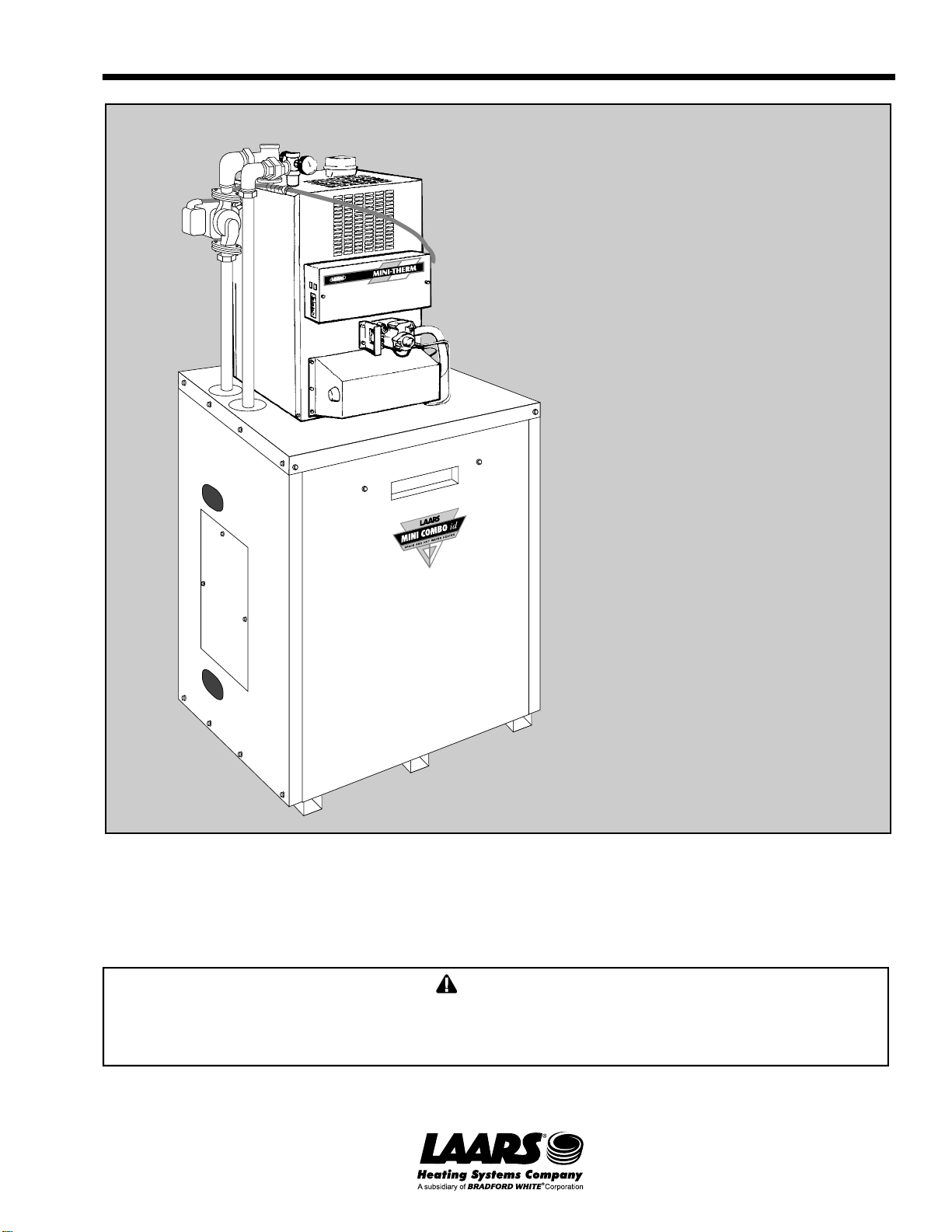
Mini-Combo id
Model MCH
Induced Draft
Residential Gas-Fired
Space/Water Heater
Note: This document is to be used in conjunction with Document 1080, Installation and Operating
Instructions for Mini-Therm JVi boilers.
WARNING
Improper installation, adjustment, alteration, service or maintenance can cause injury or property
damage. Refer to this manual. For assistance or additional information consult a qualified installer,
service agency, gas supplier, or call the factory.
H2100200B
Page 2

Page 2
LAARS Heating Systems
TABLE OF CONTENTS
SECTION 1.
General Information
1A. Hazards and Your Safety —
Hot Water Can Scald!...................................3
SECTION 2.
Installation .................................................
2A. Location........................................................ 5
2B. Heater Placement.........................................5
2C. Piping ........................................................... 5
2D. Wiring ...........................................................6
3
Page 3
Mini-Combo id
Page 3
SECTION 1.
General Information
WARNING
This manual supplies information on the application,
installation and operation of the indirect water
heater unit.
operation of the hydronic boiler (Document 1080) is
supplied along with this manual. Both manuals
should be reviewed completely before proceeding
with the installation.
• Failure to follow the instructions provided may
result in personal injury, death or substantial
property damage.
• Any modifications to the boiler, water tank, gas
and water connections, or wiring may void
warranty.
• Consult the factory or local factory
representative with any questions or problems
regarding this equipment.
Hazards and Your Safety — Hot Water
Can Scald!
Consumer Product Safety Commission and some
states/provinces recommend a temperature setting of
130°F (54°C) or less. The water heater thermostat is
factory set to approximately 120°F (49°C). If
thermostat will be set above factory setting, install an
anti-scald valve at either the water heater or at each
hot water faucet.
A complete instruction manual of the
• Studies have indicated that dangerous bacteria
can form in potable water distribution system if
certain minimum water temperatures are not
maintained. Contact local health department for
more information.
SECTION 2.
Installation
This installation must conform with the
instructions in this manual and, where applicable:
• Local, state, provincial, and national codes, laws,
regulations and ordinances.
• In Canada — CAN/CGA B149.1 or B149.2
installation Code.
Where the recommendations made in this manual
differ from local or national codes, the local or
national codes take precedence.
2A. Location
This water heater/boiler unit is not intended for
outdoor installation. Select a convenient location
where water leakage from the tank or connections will
not result in damage to areas adjacent to the appliance
or to lower floors of the structure. When a safe
location cannot be found, install a suitable drain pan
under the appliance, and pipe it to an adequate drain.
• Tempering valves are not anti-scald valves since
they do not have a positive shutoff in case cold
water supply fails. They are not recommended
for shower/tub service. If needed, install an antiscald valve at each shower/tub.
• Water heated to a temperature suitable for
clothes washing, dish washing and other
sanitizing needs can scald and cause permanent
injury.
• Children and elderly, infirm, or physically
handicapped persons are more likely to be
injured by hot water. Never leave them
unattended in a bathtub or shower. Never allow
small children to use a hot water tap or draw
their own bath. If anyone using hot water in the
building fits this description, or if state/province
laws or local codes require certain water
temperature at hot water taps, take special
precautions:
Install an anti-scald valve at water heater or at
each hot water faucet, bath, and shower outlet.
Use lowest practical temperature setting.
2
(51)
63.5
(1613)
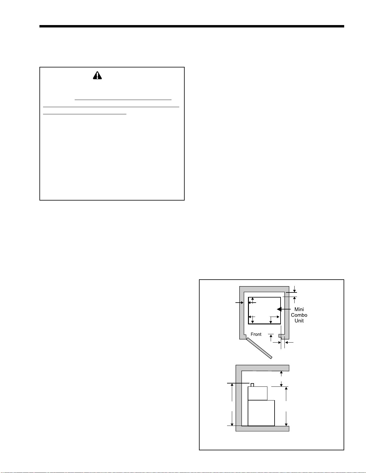
Figure 1. Closet Installation.
25.25
(641)
29
(737)
4 (102)
Top Clearance
23 (584)
57.75
(1467)
2 (51)
2
(51)
Dimensions
shown in inches
(mm).
Page 4
Page 4
Check Valve
Tank
Pump
.75
(19)
24
(610)
Domestic
Hot Water
Outlet
Cold Water
Inlet
32.5
(826)
62.5
(1588)
41.5
(1054)
Tank
Aquastat
Drain
Valve
LAARS Heating Systems
Boiler Flue Collar 4 (102)
60
(1521)
Tank
Relief
Valve
24
(610)
7
(178)
(610)
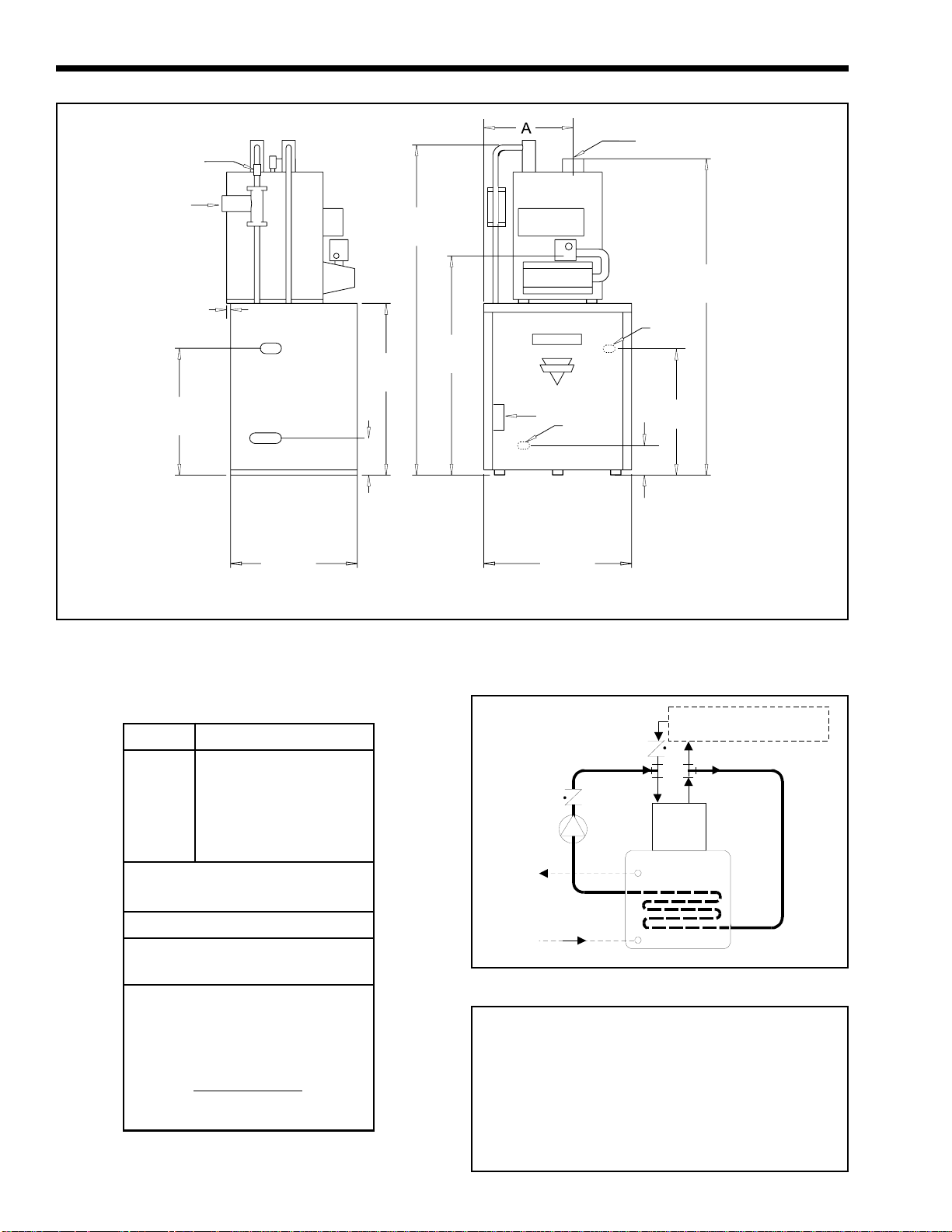
Figure 2. Dimensional Information.
Dimensions inches mm
Size A
50 14 356
75 15 381
100 16 406
125 17 432
Boiler In/Out NPT
(all sizes) 1¼
Gas NPT (all sizes) ½*
Domestic Hot Water (all sizes)
Inlet/Outlet NPT ¾
Minimum clearances from
combustible surfaces:
Left Side: 2" 51mm
Right Side: 2" 51mm
Rear: 2" 51mm
Front: 4" 102mm Top: 23" 584mm
Service clearances:
Allow 4" 102mm on each side
for piping access.
7
(178)
24
Side View Front View
Hot
Water
Supply
Cold
Water
Supply
28
(711)
Figure 3. Piping Schematic.
Dimensions shown
in inches (mm).
Space Heating -
Refer to Doc u me n t 1 080
Boiler
Tank
*¾" for model 125 Natural.
Figure 4. Typical Expansion Tank Installation.
Page 5

Mini-Combo id
Page 5
2B. Heater Placement
The heater must be placed to provide clearances
on all sides for maintenance and inspection. Allow 4
inches on each side for piping access. There must also
be minimum distances maintained from combustible
surfaces. Figure 1 shows minimum clearance from
combustible surfaces. The Mini-Combo unit can be
installed in a closet, as long as the minimum
clearances are maintained. Special attention should be
paid to the air supply opening to the closet. Refer to
Table 1.
Net Free Area — square inches sq. cm
Model Inside Air Outside Air
MC50 100 645 15 97
MC75 100 645 20 129
MC100 100 645 25 161
MC125 125 806 32 206
Area indicated is for one of two openings: One at floor level and
one at the ceiling, so the total free area would be double the
figures indicated. Refer to Document 1080 for more information.
Table 1. Minimum Recommended Air Supply.
persons. Attach run-off tube to T&P valve and
run tube within 6" (152mm) from floor. No
reducing couplings, valves, or any other type of
restriction is to be installed in this line. This runoff tube must be installed to allow free and
complete drainage of both valve and run-off tube.
• Filling Storage Water Tank
1. Open hot water faucet in house to allow air
in the tank and in piping to escape.
2. Open shut-off valve(s) in cold water supply
line.
3. Open shut-off valve(s) in hot water supply
line.
2C. Piping
• To prevent damage to the unit, all soldering is to
be done prior to assembling the cold and hot
water, and any other connections to the tank.
• Use suitable pipe dope or tape.
• Before piping the boiler to the heating system,
be sure to install the system check valve
(provided with the unit) onto the inlet (return)
tee of the boiler with arrow pointed downward
(see Figure 3).
• If anti-freeze is used in boiler system, local codes
may require a backflow preventer on cold supply
line. Use anti-freeze specifically intended for
hydronic heating system. Inhibited propylene
glycol is recommended.
WARNING
Do not use automotive or ethylene glycol antifreeze, or any undiluted anti-freeze. This can
cause severe personal injury, death or substantial
property damage.
If a backflow preventer, pressure reducing valve
or check valve is in cold water supply, install an
expansion tank on cold water supply line (see
Figure 4) to prevent normal thermal expansion from
repeatedly forcing open the T&P relief valve.
• T&P relief valve's discharge piping must be
directed so that hot water flows away from all
Figure 5. MCH Schematic.
Page 6

Page 6
LAARS Heating Systems
WALL
THERMOSTAT
(FIELD
SUPPLIED)
R
W
A
TERMINAL
STRIP
BL
SENSOR
R
AQUASTAT
(OPTIONAL)
BK - BLACK
W-WHITE
R-RED
Y-YELLOW
BL - BLUE
BR - BROWN
O-ORANGE
P-PURPLE
G-GREEN
BL/Y - BLUE/YELLOW STRIPE
BR/Y - BROWN/YELLOW STRIPE
IF ANY OF THE ORIGINAL WIRE (AS
SUPPLIED WITH THE APPLIANCE) MUST
BE REPLACED, IT MUST BE REPLACED
WITH APPLIANCE WIRING MATERIAL
SUITABLE FOR 105 DEGREES C OR ITS
EQUIVALENT
115V-FACTORY WIRED
115V-FIELD WIRED
24V-FACTORY WIRED
24V-FIELD WIRED
Figure 6. Wiring Diagram.
BR
P
R
PRESSURE
SWITCH
ROLL-OUT
SAFETY
SWITCH
AQUASTAT
R
HIGH
LIMIT
TANK
24V
COM
SEN
NC
P
GAS VAL VE
MOLEX
COM
BL
TRANSFORMER
R
NO
P
O
BL
Y
R
O
Y
Y
P
24V 115V
G
Y
R
R
Y
R
R
BL
Y
R
R
R
4
265
4
265
4
265
ZONE
PUMP
RELAY
1
3
1
3
TANK
PUMP
RELAY
1
INDUCER
MOTOR
RELAY
3
BK
W
BK
BK
BR
BK
BR
PUMP
(FIELD
SUPPLIED)
BR
INDUCER
W
W
Y
W
HOT
115/60HZ
POWER SUPPLY
NEUTRAL
GROUNDING
CONDUCTOR
TANK
PUMP
MODEL MCH
H2021000A
4. When water discharges from the faucet,
close it. Check for system leaks and repair
if necessary.
• Filling and connecting boiler pipes:
Consult the JV boiler manual, Document 1080.
Caution
Never use water heater/boiler unless it is
completely filled with water.
2D. Wiring
Priority System: Under this wiring the storage
tank will be supplied before space heating. This will
insure that it gets adequate hot water flow from the
boiler to maintain a fully rated delivery of domestic
hot water.
Caution
In this priority mode, any demand for space heating
is postponed until the storage water tank has
reached set temperature. This delay in supplying
the space heating zones is usually not noticed by
the inhabitants of the living spaces. However, in the
event of certain storage water tank malfunctions,
space heating could be delayed indefinitely. If
undetected and un-corrected, freezing damage to
piping could result.
WARNING
Electrical shock can cause severe personal injury or
death. Disconnect power supply to the boiler before
doing any electrical work.
Electrical Connection (see Figures 5 and 6).
1. Remove the two screws attaching the front cover
of the control box.
2. There are six wires coiled in the area on the right
side of the control box, supplied with wire nuts:
2 black wires twisted together, 3 white wires
twisted together, and a brown wire.
3. Follow the schematics in Figures 5 and 6.
Remove the wire nut from the two black wires,
and connect the hot lead from a 115 volt power
supply to both wires. Secure the three wires in
the wire nut.
4. The three white, neutral wires should be joined
to the other neutral lead coming from the 115
volt power supply, and the neutral lead coming
from the pump (space heating).
5. The brown wire attaches to the hot side of the
space heating pump.
Page 7

Mini-Combo id
Page 7
115 Volts Supply
Transformer
Sequence of Operation
Tank Stat
(common)
Domestic Demand
(N.C.)
Tank Pump
(energized)
Heating Demand
(N.O.)
Heating Pump
(energized)
High Limit
Switch
Inducer
Energized
Fan Proving
Switch
Flame Roll-Out
Safety Switch
Main Gas Valve
(energized)
Figure 7. Sequence of Operation.
Boiler On
Page 8

Page 8
LAARS Heating Systems
Figure 8. Parts Identification.
Page 9

Mini-Combo id
# Qty Part # Description
1 1 20085700 Weldment, Panel, Base
2 1 20085600 Weldment, Panel, Top
3 1 20086300 Weldment, Panel, Door
4 1 20086400 Panel, Side, Right
5 1 20127900 Weldment, Panel, Side, Left
6 1 20085900 Panel, Rear
7 1 20086500 Panel, Access
8 1 20084000 Bracket, Mounting, Left
9 4 20085400 Bracket, Support, Tank
10 2 P2019200 Cross, Black Iron, 1¼" NPT
11 4 P2014800 Fitting, Brass Compression,
7
/8" OD x ¾"
12 1 A2085600 Valve, Check, ¾" NPT
7
13 7.2ft P2015000 Tubing, Copper, Type “L”,
/8" OD
14 1 A2085700 Valve, Drain, Tank, ¾" NPT
15 1 E0205000 Temperature Control, Electronic
16 1 A2085400 Valve, Relief, Temp & Pressure
17 1 A2085301 30 Gal. Water Tank,
Double Wall HX
1 A2085300 30 Gal. Water Tank,
Single Wall HX
18 2 20087300 Door Latch Assembly
19 1 A0066500 Pump, Circulator
20 1 A2086600 Valve, Check, 1¼" NPT
21 1 A2087600 Handle, Door
22 2 A2086700 Flange, Pump, ¾" NPT
23 1 A2085900 Well, Immersion, ¾" NPT
24 1 A2000400 Gauge, Pressure/Temperature
25 1 A2000600 Gauge, Temperature
26 1 20084001 Bracket, Mounting, Right
27 1 E2103100 Sensor
Page 9
Page 10

Page 10
LAARS Heating Systems
Page 11

Mini-Combo id
Page 11
Page 12

Laars Heating Systems Company reserves the right to change specifications, components, features, or to discontinue products without notice.
800.900.9276 • Fax 800.559.1583 (Customer Service, Service Advisors)
20 Industrial Way, Rochester, NH 03867 • 603.335.6300 • Fax 603.335.3355
1869 Sismet Road, Mississauga, Ontario, Canada L4W 1W8 • 905.238.0100 • Fax 905.366.0130
www.Laars.com Litho in U.S.A. © Laars Heating Systems 0806 Document 2101B
H2100200B
 Loading...