

LAARS Mighty Therm LO-NOx VW User Manual
Installation, Operation and Maintenance Instructions Document 2137A
OUT OF
PRODUCTION
Installation, Operation
and Maintenance
Instructions for
TM
Mighty Therm
LO-NOx
Volume Water Heater
Model VW-PW
Sizes 250/400
For Natural Gas Only
U.S. Reg. 1,483,289
Canada Reg. 333,796
FOR YOUR SAFETY : This product must be installed and serviced by a professional service technician,
qualified in hot water heater installation and maintenance. Improper installation and/or operation could
create carbon monoxide gas in flue gases which could cause serious injury, property damage, or death.
Improper installation and/or operation will void the warranty.
Do not store or use gasoline or other flammable vapors and liquids in the vicinity of this or
any other appliance.
WARNING
If the information in this manual is not followed exactly, a fire or explosion may result
causing property damage, personal injury or loss of life.
WHA T TO DO IF YOU SMELL GAS
• Do not try to light any appliance.
• Do not touch any electrical switch; do not use any phone in your building.
• Immediately call your gas supplier from a nearby phone. Follow the gas supplier's
instructions.
• If you cannot reach your gas supplier, call the fire department.
Installation and service must be performed by a qualified installer, service agency, or gas
supplier.
H0250000A

Page 2
LAARS Heating Systems
TABLE OF CONTENTS
SECTION 1.
General Information
1.1 Introduction.................................................... 3
1.2 Warranty........................................................ 4
SECTION 2.
Installation Instructions
2.1 General Information....................................... 4
2.2 Field Assembly .............................................. 4
2.3 Site Location.................................................. 6
2.3.1 Installation Information .................................. 6
2.3.2 Outdoor Installation (U.S. only) ..................... 6
2.3.3 Flooring - Typical Installation......................... 6
2.4 Combustion and Ventilation Air Supply .........7
2.4.1 Outdoor Air Supply ........................................ 8
2.4.2 Indoor Air Supply...........................................8
2.4.3 Exhaust Fans or Vents .................................. 8
2.5 Venting (Category I) ......................................8
2.5.1 General Information....................................... 8
2.5.2 Common Venting System.............................. 8
2.5.3 Inspection of Commonly Vented
Appliances..................................................... 9
2.6 Water Flow ..................................................10
2.6.1 Water Chemistry.......................................... 10
2.6.2 Water Hardness .......................................... 10
2.6.3 Freeze Protection ........................................ 10
2.6.4 Pump Requirements.................................... 10
2.6.5 Pressure Buildup in Water System.............. 11
2.6.6 Pressure Relief Valve.................................. 13
2.6.7 Water Pressure ........................................... 13
2.6.8 Storage Tank Installation............................. 13
2.6.9 Thermal Circulation of Hot Water
in Cold Water Supply Lines ......................... 13
2.7 Gas Supply and Piping
(Natural Gas Only) ...................................... 13
2.7.1 General Instructions ....................................13
2.8 Electrical Wiring........................................... 14
PRODUCTION
OUT OF
SECTION 3.
Operating Instructions
3.1 Start-Up Procedure ..................................... 15
3.2. Setting the Temperature Controls ............... 15
3.2.1 Remote Water Heater Temperature
Control......................................................... 15
3.2.2 Internal Water Heater
Temperature Control ...................................15
3.3 Hi-Limit Switch Checkout ............................ 22
3.4 Shut-Down Procedure ................................. 22
SECTION 4.
Maintenance
4.1 General Instructions ....................................22
4.2 Heat Exchanger........................................... 22
4.2.1 Inspecting the Heat Exchanger ................... 22
4.2.2 Cleaning the Heat Exchanger ..................... 23
SECTION 5.
Troubleshooting and Service
5.1 Gas Pressure Tests..................................... 23
5.1.1 Checking the Main Line Gas Pressure ........ 23
5.1.2 Checking the Manifold
Regulated Gas Pressure ............................. 24
5.2 Electrical Troubleshooting ........................... 24
5.2.1 Heater Does Not Come On ......................... 24
5.2.2 Testing the Transformer .............................. 25
5.2.3 Testing the Electrical Power Supply ............ 25
5.2.4 Testing the Manual Reset
Hi-Limit Switch............................................. 25
5.2.5 Testing the Flow Switch............................... 26
5.2.6 Testing the Fusible Link
(flame roll-out switch) .................................. 26
5.2.7 Testing the Fuse.......................................... 26
5.2.8 Testing the Ignition Control..........................26
5.2.9 Combustion Air Blower................................26
5.2.10 Heater Will Not Shut Off .............................. 27
SECTION 6.
Replacement Parts
6.1 Ordering Information ................................... 27
6.2 Parts List ..................................................... 27
Mighty Therm LO-NOx Volume Water Heater
MIGHTY
THERM
Page 3
SECTION 1.
General Information
1.1 Introduction
This manual provides installation, operating, and
maintenance instructions for Model VW-PW Volume
Water Heaters, Sizes 250 and 400. Review all
application and installation procedures completely
before proceeding with the installation. Experience has
shown that most operating problems are caused by
improper installation.
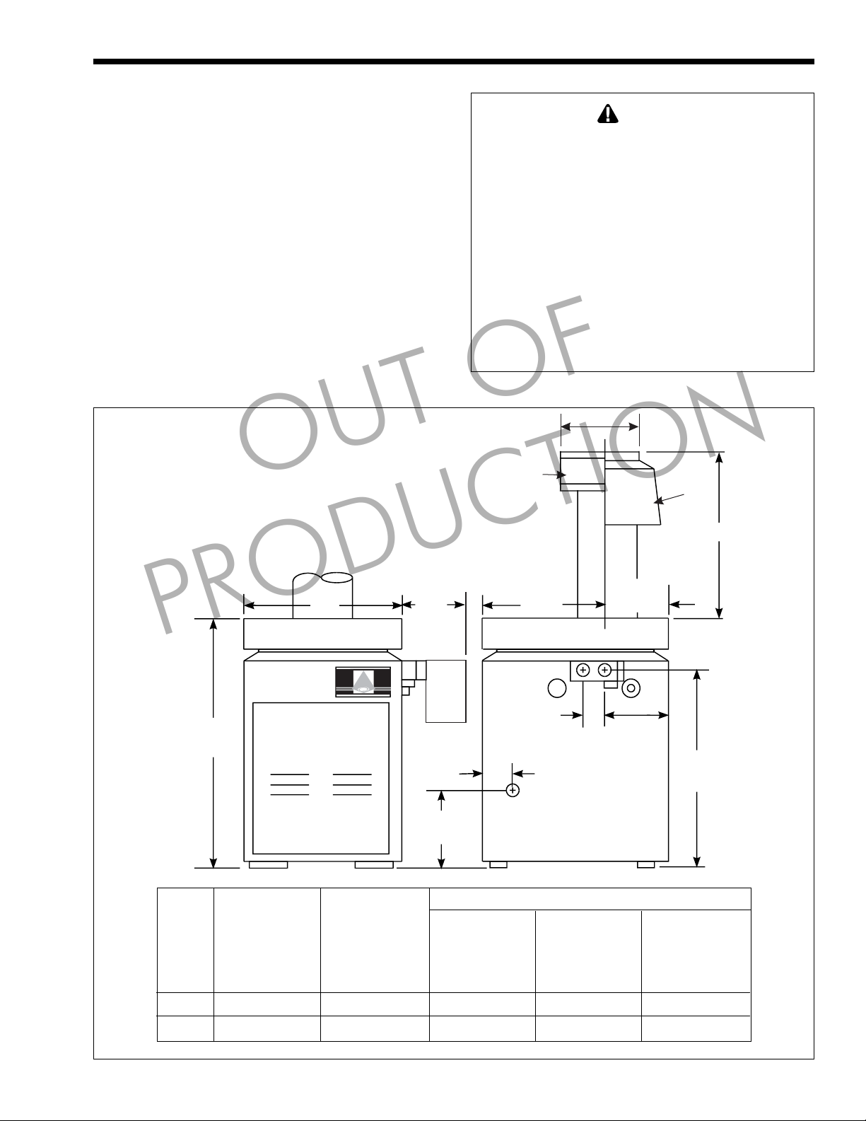
The heaters are offered in a basic configuration
(see Figure 1). On PW heaters, a factory-supplied
pump is mounted on the unit. PW models are not
available for hard water applications. There is no pump
mounted on VW units. Pump for VW units is to be
field-supplied.
NOTE:* For outdoor models, add 6 inches (15.2cm) for
outdoor base.
OUT OF
WARNING
Mighty Therm water heaters must be installed in
accordance with the procedures detailed in this
manual, or the Laars Heating Systems warranty will
be voided. The installation must conform to the
requirements of the local jurisdiction having
authority, and, in the United States, to the latest
edition of the National Fuel Gas Code, ANSI
Z223.1. In Canada, the installation must conform to
the latest edition of CAN/CGA-B149.1 Natural Gas
Installation Code and/or local codes. Any
modifications to the boiler, its gas controls, or wiring
may void the warranty. If field conditions require
modifications consult the factory representative
before initiating such modifications.
V
Vent Cap
Drafthood
Dimensions shown in
inches centimeters
W
10 1/4
26
16 1/2
41.9
10
25.4
H
PRODUCTION
MIGHTY THERM
LO-NOx
LAARS
38*
96.5
Front View Side View
Model Firing Heater
Size Rate Width
Btu/hr
(1000's)
250 250 73.3 22 1/2 57.2 7 17.8 18 1/4 46.4 25 1/4 64.1
400 399 117.0 31 3/4 80.6 9 22.9 21 1/2 54.6 27 1/2 69.9
kW in cm in cm in cm in cm
“W” “V” “H” “H”
Pump
5 1/4
13.3
3 1/2
9
GAS CONNECTION
14 3/4*
37.5
Drafthood Vent Outdoor Indoor
Vent Cap Diameter Dim Dim
FAR SIDE
Venting Dimensions
8
20.3
30 1/2*
77.5
All dimensions are nominal.
Figure 1. General Configuration.

Page 4
LAARS Heating Systems
1.2 Warranty
Laars Heating Systems Mighty Therm heaters are
covered by a limited warranty . The owner should fill
out the warranty registration card and return it to Laars
Heating Systems.
All warranty claims must be made to an
authorized Laars Heating Systems representative or
directly to the factory . Claims must include the serial
number and model (this information can be found on
the rating plate), installation date, and name of the
installer. For specific warranty conditions refer to your
Limited W arranty.
Some accessory items are shipped in separate
packages. Verify receipt of all packages listed on the
packing slip. Inspect everything for damage
immediately upon delivery, and advise the carrier of
any shortages or damage. Any such claims should be
filed with the carrier. The carrier, not the shipper, is
responsible for shortages and damage to the shipment
whether visible or concealed.
SECTION 2.
OUT OF
Installation Instructions
for outdoor installations. In special circumstances an
outdoor vent cap may be required. Check the part
number on the rating plate.
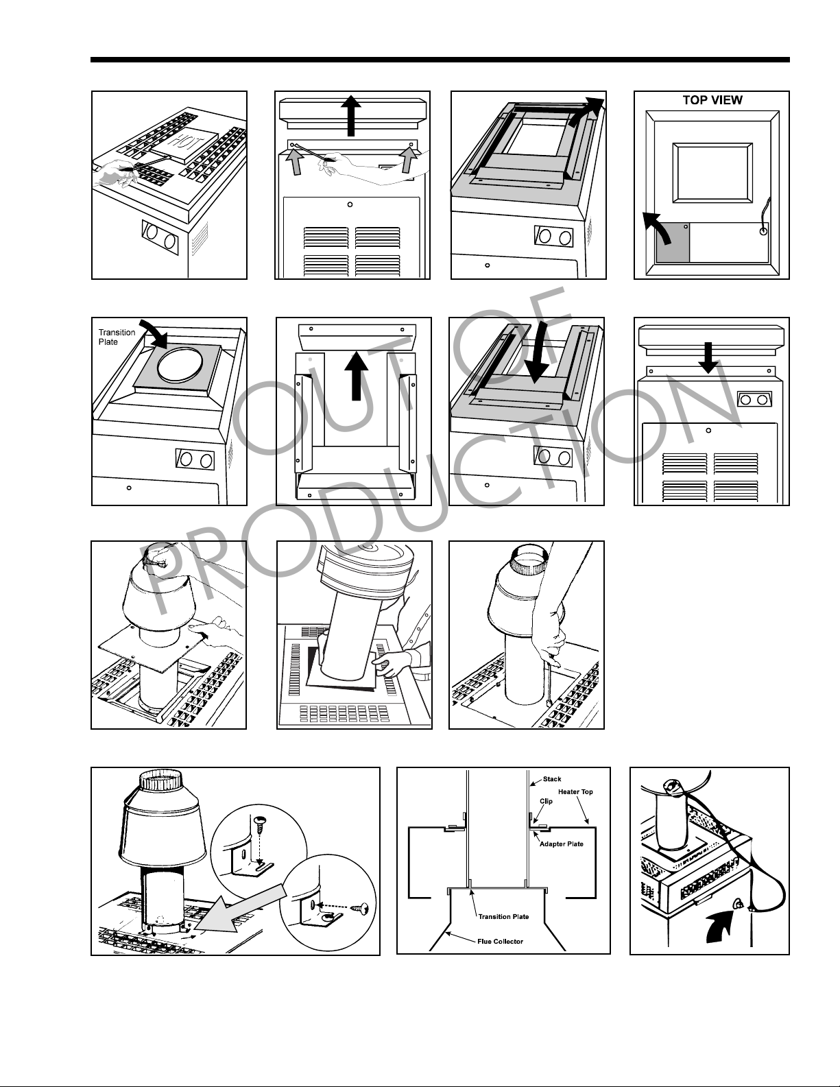
The VW, PW heaters are design certified for
indoor installation when equipped with a special
drafthood, which must be installed without
modification. The part number for the drafthood is on
the heater rating plate. Follow this procedure to make
the conversion:
1. Remove the top plate, stamped "HOT", by
slipping a fine-blade screwdriver into the slot and
prying it up (see Figure 2).
2. Remove the top by removing all eight screws
connecting it to the jacket (see Figure 3).
3. Remove the rainguard assembly (see Figure 4).
4. Remove the two screws securing the left
vestibule cover (see Figure 5). The cover can be
discarded.
5. Remove the vent cap or drafthood and
accessories from the carton.
6. Place transition plate (with 14" long side)
securely on top of flue collector so flue gases will
not leak (see Figure 6).
2.1 General Information
WARNING
Improper installation or maintenance can cause
nausea or asphyxiation from carbon monoxide in
flue gases which could result in sever injury,
property damage or death. Follow the manufacturer’s maintenance schedule for the appliance. Follow
local regulations with respect to installation of
carbon monoxide (CO) detectors.
All gas-fired products require correct installation
to assure safe operation. The requirements for heaters
include the following:
1. Field assembly of drafthood or vent cap (see
Section 2.2).
2. Appropriate site location clearances and flooring.
3. Sufficient combustion and ventilation air.
4. Adequate venting of combustion products.
5. Adequate water flow .
6. Properly sized gas meter and piping.
7. Proper electrical wiring.
This manual provides the information needed to
meet these requirements. Review all application and
installation procedures completely before continuing
the installation.
2.2 Field Assembly
The VW-PW heaters are shipped from the factory
with the top assembly in the low-profile configuration
PRODUCTION
7. Remove back portion of rainguard (see Figure 7).
8. Re-install the rainguard (see Figure 8).
9. Replace heater top and all eight screws (see
Figure 9).
10. Slide the adapter plate up over the bottom of the
stack extension. Fit the stack extension, of the
drafthood or the vent cap, on top of the collar of
the flue transition plate (see Figures 10 and 11).
11. Seat the adapter plate on the top assembly , and
secure it with screws supplied in the kit (see
Figure 12).
12. Attach the clips to the adapter plate by securing
the slotted side of the clips with the screws in the
kit (see Figure 13).
13. Use the holes in the clips as guides to drill three
1/8" dia. holes in the stack.
14. Secure the stack to the clips with the screws
supplied in the kit (see Figure 13).
15. Figure 14 shows a cross-section of the finished
installation.
16. Indoor models, size 250 only , require an adapter
cable (included with product). The cable connects
the blocked vent safety switch (BVSS) on the
bell of the external draft hood to the 6-position
Molex plug on the side of the unit (see Figure
15). Refer to instruction sheet included with
cable.
Mighty Therm LO-NOx Volume Water Heater
Page 5
Figure 2. Figure 3.
Figure 4. Figure 5.
OUT OF
Figure 6. Figure 7. Figure 8. Figure 9.
PRODUCTION
Figure 10. Figure 11.
Figure 13. Figure 14.
Figure 12.
Figure 15. Drafthood
Switch Receptacle.
Page 6
2.3 Site Location
2.3.1 Installation Information
WARNING
Improper installation or maintenance can cause
nausea or asphyxiation from carbon monoxide in
flue gases which could result in severe injury,
property damage, or death.
A void placing the heater in locations where it can
cause damage by water or condensate leakage. If this is
not possible, provide a suitable drain pan under the
heater to catch and divert any leakage. The pan must
not restrict air flow around the heater.
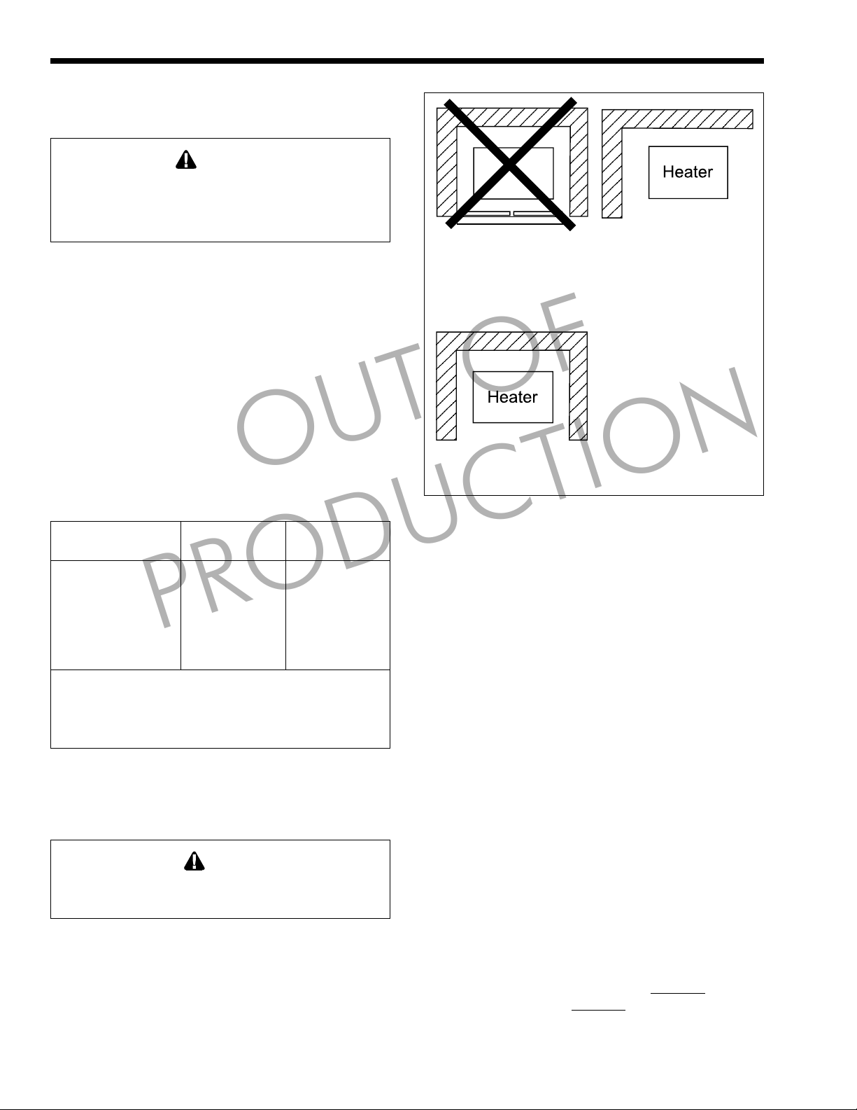
Locate the heater to provide adequate clearance
on all sides for inspection, service and to provide
adequate air circulation for proper operation.
Locate the heater so the clearances from
combustible surfaces shown in Table 1 and Figure 16
are met.
Locate the heater on a waterproof floor with a
floor drain and a 6 inch (152 mm) minimum curb on
all four sides to protect the building if heater repairs
are needed.
Clearance from: inch cm inch cm
Top 37 94 Unobstructed
Water conn. side 12 30.5 Unobstructed
Opposite side 6 15.2 6 15.2
Front Alcove Unobstructed
Rear 6 15.2 6 15.2
Vent* 6 15.2 —
Flooring: Combustible
Service clearance = 36 inches (91.4cm) at front of heater,
and 18 inches (46cm) at water connection side.
*1" (2.5cm) if double wall vent is used.
6" base for outdoor boiler is required.
Table 1. Minimum Boiler Clearances
PRODUCTION
from Combustible Surfaces.
2.3.2 Outdoor Installation
Outdoor installations are not recommended in areas
where the danger of snow blockage exists.
a. Locate the heater in an open, unroofed area. Do
not locate the heater below or adjacent to any
doors, windows, louvers, grills, etc., which
connect in any way with an inhabited area of a
building, even though the access might be
through another structure such as a garage or
utility room (see Figure 17 and Table 1).
OUT OF
Indoors Outdoors
Caution
LAARS Heating Systems
Closet Installation
(unacceptable)
A closet is any 4 sided enclosure
which is less than 16* times the
total volume of all the gas fired
appliances within the enclosure.
REAR
FRONT
* When the ceiling height exceeds 8 feet, you are only allowed to
consider 8 feet when calculating the total volume of the enclosure.
Figure 16. Alcove Installation.
Room Installation
(acceptable)
A room is any enclosure which is
at least 16* times greater than the
total volume of all the gas fired
appliances within the enclosure
Alcove Installation
(acceptable)
An alcove suitable for the
installation of a heater is a
restricted section of a room not
separated from the room by a door
or partition and which meets the
minimum clearances specified in
this manual.
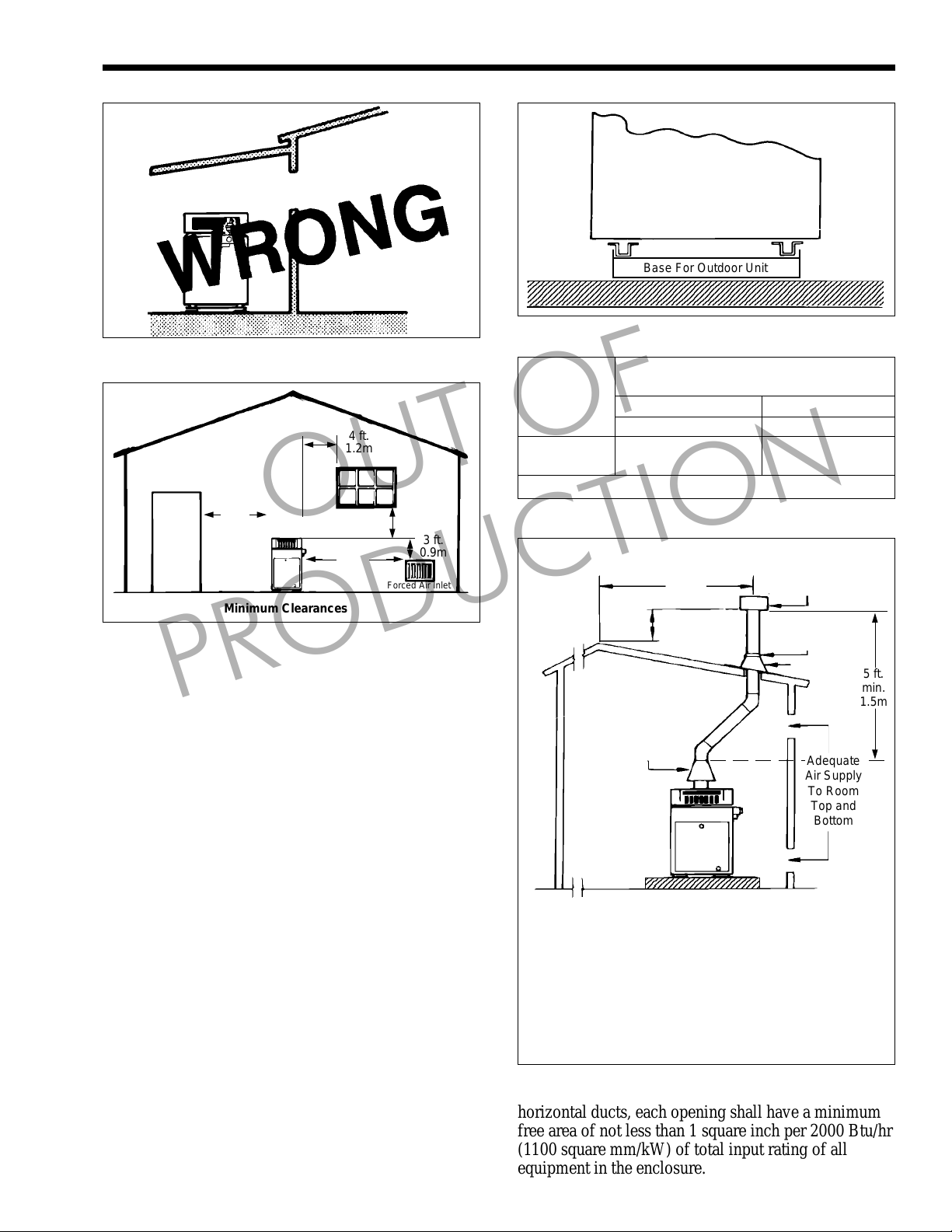
b. There must be a minimum of 4 feet (1.22 m)
horizontally and vertically between the heater
and any door, window, or gravity inlet to a
building (see Figure 18).
c. Minimum clearance of 4 feet (1.22m) [6 feet
(1.83m) in Canada] horizontally from, and in no
case above or below , unless the minimum
horizontal distance is maintained, from electric
meters, gas meters, regulators and relief
equipment.
d. If the heater is installed close to a structure,
protect it from rain water runoff with rain gutters
on the roof or other measures. Do not locate the
heater near sprinkler systems that could spray
water on it.
e. Avoid locations where wind deflection off nearby
structures might cause wind loading and
downdraft conditions. Where downdraft
conditions exist, locate the heater at least 3 feet
(0.91 m) from the structure.
2.3.3 Flooring - T ypical Installation
All outdoor boilers must be installed with the
special base, as a standard part of the heater. The base,
part number R0368900, is provided in a separate
package. The heater is designed and certified for
installation on combustible flooring.
the heater on carpeting.
NEVER store objects on or
NEVER install
around the base of the heater. For outdoor base
installation, see Figure 18.
Mighty Therm LO-NOx Volume Water Heater
123456789012345678901234567890121234567890123456789012345678901212345
1
5
1
5
1
5
123456789012345678901234567890121234567890123456789012345678901212345
3
Page 7
WINDOW
OR GRILL
INDOOR
ROOM
Figure 17. Incorrect Outdoor Installation.
4 ft.
1.2m
4 ft.
1.2m
Minimum Clearances
Figure 18. Outdoor Location Installation.
OUT OF
10 ft.
3.0m
4 ft.
1.2m
3 ft.
0.9m
Forced Air Inlet
2.4 Combustion and Ventilation
Air Supply
PRODUCTION
All indoor installations must have openings to
outside air for combustion, ventilation and dilution of
flue gases from inside the building (see Figure 20 and
T able 2 ). Laars does not recommend indoor
installations that do not provide combustion air from
outside the building.
In the United States, the most common
requirements specify that the space (enclosure) shall
communicate with the outdoors in accordance with
method 1 or 2, which follow . Where ducts are used,
they shall be of the same cross-sectional area as the
free area of the openings to which they connect.
Method 1:
T wo permanent openings, one commencing
within 12" (30 cm) of the top and one commencing
within 12" (30 cm) of the bottom of the enclosure shall
be provided. The openings shall communicate
directly, or by ducts, with the outdoors or spaces that
freely communicate with the outdoors. When directly
communicating with the outdoors, or through vertical
ducts, each opening shall have a minimum free area of
1 square inch per 4000 Btu/hr (550 square mm/kW) of
total input rating of all equipment in the enclosure.
When communicating to the outdoors through
LAARS
UNIT
(Side View)
2345678901234567890123456789012123456789012345678901234567890121234
2345678901234567890123456789012123456789012345678901234567890121234
2345678901234567890123456789012123456789012345678901234567890121234
Figure 19. Base for Outdoor Installation.
Model in.
250 63 406 63 406
400 100 645 100 645
Note: For screens or louvers, add 50%.
Table 2. Air Openings to Outside.
Vent terminated at
least 2 ft. (61cm)
above any
object within
10 ft. (3.0m)
Notes:
1. The drafthood must sit directly on top of the heater
as shown and must not be altered in any manner.
2. A vent cap listed or certified for the application by a
Nationally Recognized Testing Laboratory (NRTL)
such as Underwriter’s Laboratories (UL) is required to
eliminate downdraft and to allow the heater to function
properly.
3. Use approved roof fitting.
Figure 20. Indoor Installation and Venting.
Base For Outdoor Unit
Required Net Free Opening Area
2
10 ft.
3.0m
2 ft. 61cm
1/4 in. 0.6cm
Minimum Pitch
Per Foot of
Horizontal Pipe
Drafthood
234567890123456789012
Directly from Outside
At Top At Bottom
cm
2
2
in.
Listed Vent
Cap
Storm Collar
Roof Jack
Adequate
Air Supply
To Room
Top and
Bottom
cm
2
5 ft.
min.
1.5m
horizontal ducts, each opening shall have a minimum
free area of not less than 1 square inch per 2000 Btu/hr
(1100 square mm/kW) of total input rating of all
equipment in the enclosure.

Page 8
LAARS Heating Systems
Method 2:
One permanent opening, commencing within 12"
(30 cm) of the top of the enclosure shall be permitted.
The opening shall directly communicate with the
outdoors or shall communicate through a vertical or
horizontal duct to the outdoors or spaces that directly
communicate with the outdoors, and shall have a
minimum free area of 1 square inch per 3000 Btu/hr
(734 square mm/kW) of the total input rating of all
equipment located in the enclosure. This opening must
not be less than the sum of the areas of all vent
connectors in the confined space.
Other methods of introducing combustion and
ventilation air are acceptable, providing they conform
to the requirements in ANSI Z223.1, or other
applicable codes.
In Canada, Table 2 does not apply. Consult local
building and safety codes or, in absence of such
requirements, follow CSA B149.1.
NOTE: Check with louver manufacturers for net free
area of louvers. If screens or louvers are installed,
add 50 percent for each screen/louver to the net free
area.
2.4.1 Outdoor Air Supply
When combustion air comes directly through an
outside wall, each opening must have a minimum free
area of at least one square inch for each 4,000 BTU/h
input of the total input rating of all appliances in the
enclosed area. (In Canada, refer to CSA-B149.1.)
OUT OF
PRODUCTION
2.4.2 Indoor Air Supply
Confined and non-confined areas have different
requirements for installation. Check the latest edition
of ANSI Z223.1 or in Canada CSA-B149.1 and all
local codes applicable to combustion air.
2.4.3 Exhaust Fans or Vents
Any equipment which uses air or removes air
from the heater room can use up the combustion air
supply or reverse the natural draft action of the venting
system. This could cause flue products to build up in
the heater room. More air must be supplied to make up
for the decrease.
2.5 V enting (Category I)
2.5.1 General Information
When installed indoors, the drafthood must be
connected to a venting system. The venting system
must be installed by a qualified installer and in
accordance with the latest edition of ANSI Z223.1. In
Canada, the installation must be in accordance with
CSA-B149.1, and any local codes that apply .
The vent pipe must have a listed vent cap, and
extend at least 2 feet (0.6 m) above any object within a
10 foot (3.0 m) radius.
NOTE: Do not use sheet metal screws at the snap
lock joints of Type B double-wall gas vents.
Do not weld or bolt the vent pipe to the heater
drafthood. The weight of the stack must not rest on the
heater. The drafthood and heater top must be easily
removable for normal heater service and inspection.
WARNING
Avoid ending heater vents near air conditioning or
air supply fans. The fans can pick up exhaust flue
products from the heater and return them inside the
building, creating a possible health hazard.
Locate unit as close as practical to a chimney or
vent termination. Have horizontal runs sloping
upwards not less than 1/4 inch per foot (21mm/m)
from the boiler to the vent terminal. Support a vent
connector for the design and weight of the material
used to maintain clearances and prevent physical
damage and separate of joints.
Doivent présenter des tronçons horzontaux dont
la pente montante est d’au moins 1/4 po par pied
21mm/m) entre la chaudière et l’évent. Doivent
préciser que les sections horizontales doivent être
supportées pour prévenir le fléchissement.
Always use double-wall or insulated vent pipe
(Type B or equivalent).
WARNING
In cold weather, uninsulated outside vents can chill
the rising flue products, blocking the natural draft
action of the venting system. This can create a
health hazard by spilling flue products into the
heater room.
A void oversize vent piping or extremely long
runs of the pipe which may cause too much cooling
and condensation of flue gases.
When the installation of a power vent or draft fan
in the venting system is necessary , qualified personnel
should design the installation following good
engineering practices and all applicable codes. A
suitable draft switch must be wired into the heater
control circuit at the terminal designated Field
Interlock to keep the heater from firing unless there is
a positive draft.
2.5.2 Common Venting Systems
Venting Multiple Appliances
When installing venting for a Mighty Therm LoNOx boiler or water heater installed as a Category I
fan-assisted appliance with other Category I appliances
through one shared duct called a “common vent”,
special care must be taken by the installer to ensure
safe operation. In the event that the common vent is

Mighty Therm LO-NOx Volume Water Heater
Page 9
blocked, it is possible, especially for fan-assisted
devices, to vent backwards through non-operating
appliances sharing the vent, allowing combustion
products to infiltrate occupied spaces. If the
appliances are allowed to operate in this condition,
serious injury or death may occur.
WARNING
Operation of appliances with a blocked common
vent may lead to serious injury or death. Safety
devices must be implemented to prevent blocked
common vent operation. If safe operation of all
appliances connected to a common vent cannot be
assured, including prevention of spillage of flue
gasses into living spaces, common venting should
not be applied, and appliances should each be
vented separately.
AVERTISSEMENT
Le fonctionnement des appareils avec un système
d’évacuation bloqué peut provoquer des blessures
graves, voire la mort. Des dispositifs de sécurité
doivent être installés pour éviter le blocage des
systèmes d’évacuation. Si le fonctionnement de
tous les appareils connectés à un système
d’évacuation commun ne peut pas être assuré, y
compris la prévention de la dispersion des gaz
toxiques dans les espaces habités, on ne devrait
pas installer un système d’évacuation commun et
chaque appareil devrait être ventilé séparément.
It is for this reason that, in addition to following
proper vent sizing, construction and safety
requirements from the National Fuel Gas Code, ANSI
Z223.1 or in Canada, from CSA B149.1 as well as all
applicable local codes, it is required that installers
provide some means to prevent operation with a
blocked common vent. It is suggested that a blocked
vent safety system be employed such that if the switch
from one appliance trips due to excessive stack spill or
backpressure indicating a blocked vent condition, that
all appliances attached to the vent be locked out and
prevented from operating. As an additional precaution,
it is recommended that a Carbon Monoxide (CO)
alarm be installed in all enclosed spaces containing
combustion appliances. If assistance is required in
determining how a blocked vent safety system should
be connected to a LAARS product, please call
Applications Engineering at (603) 335-6300.
instructions on all appliances to be common vented for
instructions, warnings, restrictions and safety
requirements. If safe operation of all appliances
connected to a common vent cannot be assured,
including prevention of spillage of flue gasses into
living spaces, common venting should not be applied,
and appliances should each be vented separately .
PRODUCTION
Refer to the installation and operating
OUT OF
2.5.3 Inspection of Commonly Vented
Appliances
If the instrumentation of this heater replaces an
older heater in a common vent system with other
appliances, or if you remove additional appliances
from the common vent, all the appliances must be
checked for proper venting.
At the time of removal of an existing heater, the
following steps shall be followed with each appliance
remaining connected to the common venting system
placed in operation, while the other appliances
remaining connected to the common venting system
are not in operation.
1. Seal any unused openings in the common venting
system.
Sceller toutes les ouvertures non utilisées du
système d’évacuation.
2. Visually inspect the venting system for proper
size and horizontal pitch and determine there is
no blockage or restriction, leakage, corrosion and
other deficiencies which could cause an unsafe
condition.
Inspecter de façon visuelle le système
d’évacuation pour déterminer la grosseur et
l’inclinaison horizontale qui conviennent et
s’assurer que le système est exampt
d’obstruction, d’étranglement, de fuite, de
corrosion et autres défaillances qui pourraient
présenter des risques.
3. Insofar as it is practical, close all building doors
and windows and all doors between the space in
which the appliances remaining connected to the
common venting system are located and other
spaces of the building. Turn on clothes dryers and
any appliance not connected to the common
venting system. Turn on any exhaust fans, such
as range hoods and bathroom exhausts, so they
will operate at maximum speed. Do not operate a
summer exhaust fan. Close fireplace dampers.
Dans la mesure du possible, fermer toutes les
portes et les fenêtres du bâtiment et toutes les
portes entre l’espace où les appareils toujours
raccordés au système d’évacuation sont installés
et les autres espaces du bùtiment. Mettre en
marche les sécheuses, tous les appareils non
raccordés au systéme d’évacuation commun et
tous les ventilateurs d’extraction comme les
hottes de cuisinière et les ventilateurs des salles
de bain. S’assurer que ces ventilateurs
fonctionnent à la vitesse maximale. Ne pas faire
fonctionner les ventilateurs d’été. Fermer les
registres des cheminées.
4. Place in operation the appliance being inspected.
Follow the lighting instructions. Adjust
thermostat so appliance will operate
continuously.

Page 10
LAARS Heating Systems
Mettre l’appareil inspecté en marche. Suivre les
instructions d’allumage. Régler le thermostat de
façon que l’appareil fonctionne de façon
continue.
5. Test for spillage at the draft hood relief opening
after 5 minutes of main burner operation. Use the
flame of a match or candle, or smoke from a
cigarette, cigar or pipe.
Faire fonctionner le brûleur principal pendant 5
min ensuite, déterminer si le coupe-tirage
déborde à l’ouverture de décharge. Utiliser la
flamme d’une allumette ou d’une chandelle ou la
fumée d’une cigarette, d’une cigare ou d’une
pipe.
6. After it has been determined that each appliance
remaining connected to the common venting
system properly vents when tested as outlined
above, return doors, windows, exhaust fans,
fireplace dampers and any other gas burning
appliance to their previous conditions of use.
Une fois qu’il a été déterminé, selon la méthode
inidquée ci-dessus, que chaque appareil raccordé
au système d’évacuation est mis à l’air libre de
façon adéquate. Remettre les portes et les
fenêtres, les ventilateurs, les registres de
cheminées et les appareils au gaz à leur position
originale.
7. Any improper operation of the common venting
system should be corrected so the installation
conforms with the National Fuel Gas Code, ANSI
Z223.1. When resizing any portion of the
common venting system, the common venting
system should be resized to approach the
minimum size as determined using the
appropriate tables in Appendix G in the National
Fuel Gas Code, ANSI Z223.1.
T out mauvais fonctionnement du système
d’évacuation commun devrait être corrigé de
façon que l’installation soit conforme au national
Fuel Gas Code, ANSI Z223.1 et (ou) aux codes
d}installation CSA-B149.1. Si la grosseur d’une
section du système d’évacuation doit être
modifiée, le système devrait être modifié pour
respecter les valeurs minimales des tableaux
pertinents de l’appendices F du National Fuel
Gas Code, ANSI Z2231.1 et (ou) des codes
d}installation CSA-B149.1.
PRODUCTION
OUT OF
2.6 Water Flow
2.6.1 Water Chemistry
Laars equipment is designed to be used in a
variety of water conditions. With the proper pump, the
water velocity in the heat exchanger tubes is kept high
enough to prevent scaling from hard water, yet low
enough to avoid erosion by soft water.
NOTE: It is possible to have hard and soft water in the
same city. Check with the local water companies.
If an installer sees damage to any water handling
equipment at the installation site, it should be repaired
as soon as possible to help reduce maintenance costs.
If there is erosion, resize the pump to reduce water
velocity before the tube ruptures. If scaling is bad, set
up a heat exchanger tube-cleaning maintenance
schedule to prevent heat exchanger tube cracking and
wear. Not fixing the condition will mean serious
damage to the heater and the water system.
NOTES: In areas where the water supply is soft or
corrosive, the heater must have cupronickel tubes in
the heat exchanger. Laars does not warrant heat
exchangers damaged by scaling, corrosion, or
erosion.
2.6.2 Water Hardness
Consider the water hardness when selecting a
pump for the heater (see Table 3). Hard water needs a
pump which can provide high flow to prevent scaling,
while soft water needs low flow to prevent erosion.
Hardness Grains per Parts
Category Gallon per Million
Soft 1 through 7.5 17 through 128
Normal 7.6 through 17 129 through 291
Hard Over 17 Over 291
Table 3. Water Hardness.
2.6.3 Freeze Protection
Although VW, PW heaters are design-certified
for outdoor installations, such installations are not
recommended in areas subject to freezing temperatures
unless proper precautions are taken.
Power outage, interruption of gas supply , failure
of system components, activation of safety devices,
etc., may prevent a heater from firing. Any time a
heater is subjected to freezing conditions, and the
heater is not able to fire, and/or the water is not
able to circulate, there is a risk of freezing in the
heater or in the pipes in the system. When water
freezes, it expands. This can result in bursting of pipes
in the system, or damage to the heater, which could
result in leaking or flooding conditions.
2.6.4 Pump Requirements
PW heaters are equipped with factory-mounted
and wired pumps. The pump is for heater-to-tank
circulation only . See Table 4 for pump performance.
PW heaters are not available for hard water applications.
VW and PW heaters are not designed for applications where the temperature of the water flowing
through the heater remains below the dew point, 110°F
(43°C).
 Loading...