

Page 1
Installation and Operation Instructions Document 2140A
Installation and Operation
Instructions for
Mighty Therm
Lo-NOx
Hydronic Boilers and
Volume Water Heaters
Models PH and PW
Sizes 500-1825
These instructions are to be stored in the pocket provided on the boiler.
FOR YOUR SAFETY: This product must be installed and serviced by a professional service technician,
qualified in hot water boiler installation and maintenance. Improper installation and/or operation could
create carbon monoxide gas in flue gases which could cause serious injury, property damage, or death.
Improper installation and/or operation will void the warranty.
W ARNING
If the information in this manual is not followed exactly, a fire or explosion may result
causing property damage, personal injury or loss of life.
Do not store or use gasoline or other flammable vapors and liquids in the vicinity of this or
any other appliance.
WHAT TO DO IF YOU SMELL GAS
• Do not try to light any appliance.
• Do not touch any electrical switch; do not use any phone in your building.
• Immediately call your gas supplier from a nearby phone. Follow the gas supplier's
instructions.
• If you cannot reach your gas supplier, call the fire department.
Installation and service must be performed by a qualified installer, service agency, or gas
supplier.
H0256700A
Page 2

Page 2
LAARS HEATING SYSTEMS
TABLE OF CONTENTS
SECTION 1.
General Information
1.1 Introduction................................................... 3
1.2 Heater Identification...................................... 3
1.3 General Flow Requirement........................... 3
SECTION 2.
Installation
2.1 Heater Placement......................................... 4
2.2 Installation of Indoor Heaters ........................ 4
2.2.1 Combustion Air Supply..................................4
2.2.1.a Conventional Ventilation ...............................4
2.2.1.b Forced-Air V entilation ................................... 5
2.2.2 Venting..........................................................5
2.2.3 Removal of Existing Heater .......................... 6
2.3 Installation of Outdoor Heaters ..................... 6
2.4 Gas Supply and Piping ................................. 6
2.5 Electrical Wiring............................................7
SECTION 3.
Water Piping Instruction
3.1 General Piping Practice ................................ 8
3.2 Heating Boiler (PH Model) ............................ 8
3.2.1 Variable Water Flow System......................... 8
3.2.2 System Pressure Requirements ...................8
3.2.3 Hot/Chilled Water Systems...........................8
3.2.4 Combined Sp ace Heating/Potable
Water Heating Systems................................ 9
3.2.5 Piping System Requirements...................... 10
3.2.6 Filling the System ....................................... 10
3.3 Water Heater (PW Model) .......................... 10
3.3.1 Water Chemistry.........................................10
3.3.2 Piping System Requirements...................... 11
3.3.3 Water Expansion ........................................ 11
3.3.4 Pump Requirements................................... 11
3.3.5 Water Pressure........................................... 13
3.3.6 Tank Installation..........................................14
3.3.7 Two-Temperature........................................ 14
SECTION 4.
Operating Instructions
4.1 Controls - General ...................................... 15
4.1.1 Electronic Ignition Control ...........................15
4.1.2 Hot Surface Igniter......................................15
4.1.3 Combustion Air Pressure Switch.................15
4.1.4 Operating Controls...................................... 15
4.1.5 High Limit Control ....................................... 15
4.1.6 Flow Switch ................................................ 16
4.1.7 Low Water Cut Off...................................... 16
4.2 S tart-Up Requirement s ............................... 16
4.3 Normal Operating Sequence ...................... 17
4.4 Hi-Limit Checkout ....................................... 17
4.5 Start-Up Procedure..................................... 17
4.5.1 Lighting Instructions.................................... 18
4.5.2 To Turn Off Gas to Appliance...................... 18
4.6 Setting the Temperature Controls ............... 18
4.6.1 Hydronic Boilers.......................................... 18
4.6.2 Water Heaters ............................................ 18
SECTION 5.
Maintenance
5.1 General Instructions.................................... 18
5.2 Combustion Air Blower ............................... 19
5.3 Heat Exchanger.......................................... 19
5.3.1 External Cleaning of Heat Exchanger .........19
5.3.2 Internal Cleaning of Heat Exchanger .......... 20
5.4 Gas and Electric Controls ........................... 20
5.5 Burner Removal and Cleaning.................... 20
SECTION 6.
Troubleshooting
6.1 Sequence of Operation............................... 20
6.2 Electrical Components................................21
6.2.1 General Troubleshooting ............................ 21
6.2.2 Electrical Troubleshooting...........................21
6.3 Mechanical Components ............................ 23
6.3.1 Pressure Relief Valves Leaking
Intermittently or S teadily..............................23
6.3.2 Heater is Pounding, Knocking or
Emitting Steam from Relief Valves..............23
6.3.3 Soot in Flueways or in Tubes, or Noxious
Fumes Indicative of Bad Combustion ......... 23
6.3.4 Water Dripping in Firebox ........................... 23
SECTION 7.
Parts Descriptions and
Order Numbers
7.1 Jack and Combustion Chamber
Components ............................................... 25
7.2 Water System ............................................. 25
7.3 Electrical Components................................26
7.4 Gas Train....................................................26
7.5 Burner Tray.................................................26
7.6 Outdoor Jacket ...........................................33
Page 3
Mighty Therm Lo-NOx
Page 3
SECTION 1.
General Information
1.1 Introduction
This manual provides information for the
installation and operation of Laars gas-fired hydronic
boilers and water heaters. It is strongly recommended
that all application and installation procedures be
reviewed completely before proceeding with the
installation. Consult the Laars factory, or local factory
representative with any problems or questions
regarding this equipment. Experience has shown that
most problems are caused by improper installation,
not system design.
Some accessory items are shipped in separate
packages. Verify receipt of all items listed on the
package slip. Inspect everything for possible damage
upon delivery, and inform the carrier of any shortages
or impairments. Any such claims should be filed with
the carrier. The carrier, not the shipper, is responsible
for shortages and damage to the shipment whether
visible or concealed.
IMPORTANT WARNING
The Laars heaters must be installed in
accordance with the procedures outlined in this
manual. The warranty does not apply to boilers not
installed or operated in accordance with these
procedures. Consult local building and safety codes
before proceeding with work. The installation must
conform to the requirements of the authority having
jurisdiction or, in the absence of such requirements, to
the latest edition of the National Fuel Gas Code;
ANSI Z223.1, National Electrical Code ANSI/NFPA
70 and/ or in Canada CAN 1 -13149 requirements.
When required by the authority having
jurisdiction, the installation must conform to
American Society of Mechanical Engineers safety
codes for controls and safety devices for automatically
fired boilers No. CSD-1, and in Canada CGA 3.3. Any
modification to the boiler, its gas controls, gas
orifices, wiring or draft diverter may void the Laars
warranty. If field conditions require such
modifications, consult factory.
1.2 Heater Identification
Consult rating plate on the boiler. The following
example simplifies the boiler identification.
1 2 3456
PH 1200 I N 21 K
(1) Basic heater model (see descriptions below).
(2) Input rate x 1000 BTU/h.
(3) Indoor (I) or Outdoor (E) installation.
(4) Gas type: Natural (N).
(5) Ignition system: (21) Hot surface (proved igniter)
ignition system.
(6) Firing modes:
On/Off (C)
2-stage (K)
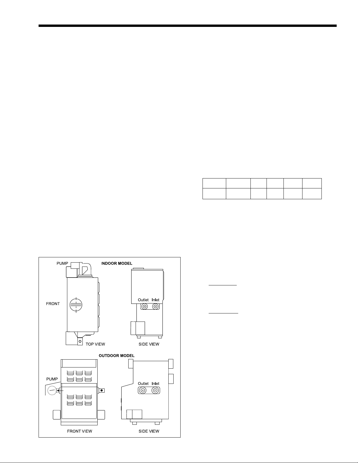
Figure 1. Boiler Configuration.
Model PH hydronic heating boilers come with
integrally mount pumps. Pumps are sized for pressure
drop through the heat exchanger only.
Model PW water heaters for use with separate
storage tank come with integrally mount pumps.
Pumps are sized for pressure drop through the heat
exchanger plus 30 feet (9.1m) of pipes and normal
fitting.
Laars heaters are available in two
configurations: an indoor version and an outdoor
version. Both are available from the factory (see
Figure 1).
1.3 General Water Flow Requirement
For proper operation, all low volume hot water
heaters must have continuous flow through the heat
exchanger when firing. The system pump must be
capable of developing sufficient pressure to overcome
the resistance of the heater plus the entire circulating
system at the designed flow rate.
Page 4
Page 4
LAARS HEATING SYSTEMS
SECTION 2.
Installation
2.1 Heater Placement
The heater must be placed to provide specific
clearances on all sides for maintenance and
inspections. There must also be minimum distances
maintained from combustible surfaces. These
clearances also apply to noncombustible materials
because the heater requires air circulation for proper
operation.
The heater should be mounted on a level surface.
An integral base for an installation on combustible
flooring is provided as standard equipment on all
models.
Do not install a heater on carpeting.
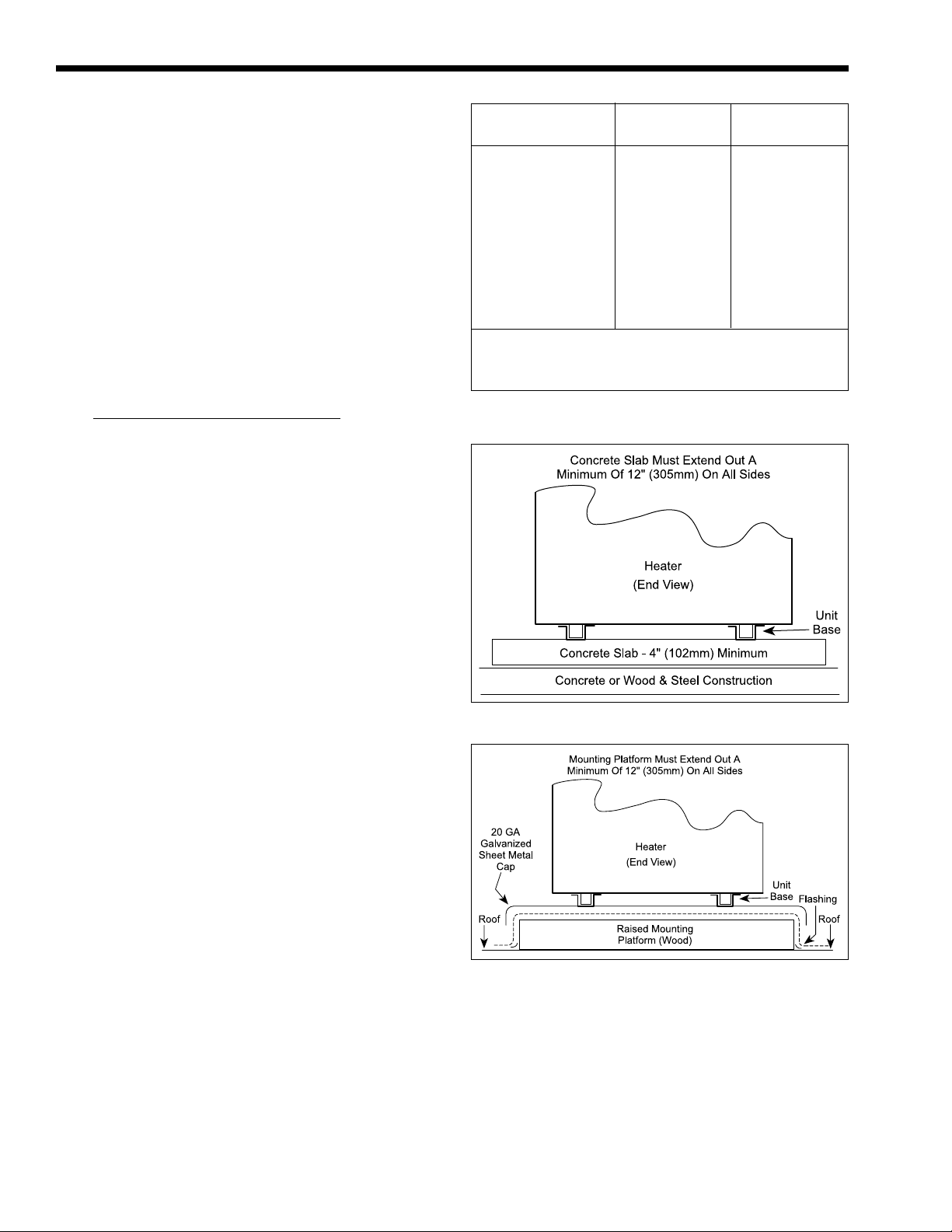
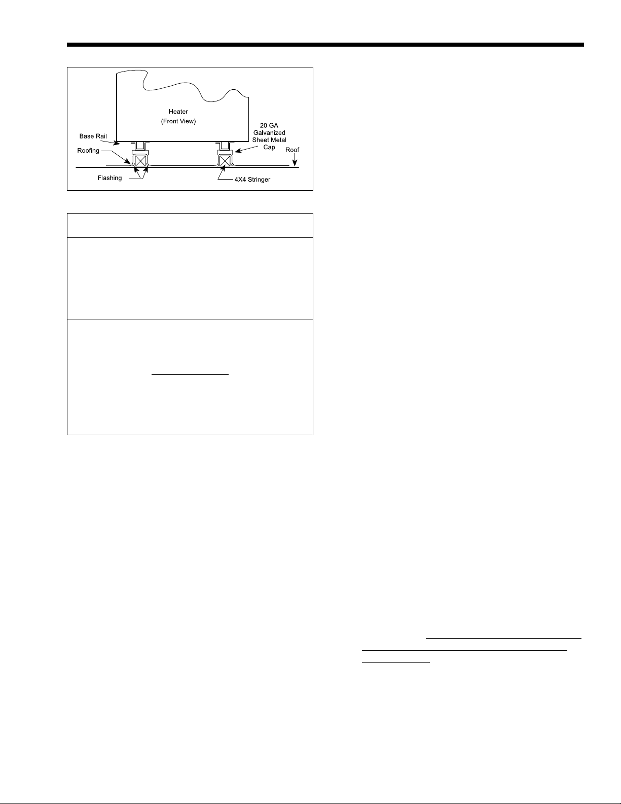
Under the national Fuel Gas Code, ANSI
Z223.1, it is permissible to place the heater on floors
other than noncombustible when the installation
complies with the American Insurance Code. Figures
2, 3, and 4 show common installation on combustible
flooring.
Clearance Indoor Outdoor
from in. mm in. mm
Top 30 762 unobstructed
Water Conn. side 12* 305 24 610
Pump side 6* 152 24 610
Front Alcove* unobstructed
Rear 8 203 24 610
Vent pipe** 6 152 - - -
Hot water pipes per code per code
* Water connection and pump side clearances of 24" (610mm)
and front clearances of 48" (1219mm) will allow easier
service access.
** One inch using type B vent (refer to Manufacturer's Instructions).
Table 1. Minimum Heater Clearances From
Adjacent Surfaces.
2.2 Installation of Indoor Heaters
Locate the heater to provide adequate clearance
for inspection and service on all sides. See Table 1.
Install indoor heaters on a waterproof floor with
an adequate floor drain and a 6" (152mm) minimum
curb on all four sides to protect the building if heater
repairs are required. The manufacturer will not be
held liable for any water damage in connection
with this heater.
2.2.1 Combustion Air Supply
The heater location must provide sufficient air
supply for proper combustion and ventilation of the
surrounding area as outlined in the latest edition of
ANSI standard Z223.1, and any local codes that may
be applicable. Inadequate combustion air supply may
result in incomplete combustion, sooting of the heat
exchanger, and unsafe operation of the boiler.
2.2.1.a Conventional Ventilation
In the United States, the most common
requirements specify that the space shall communicate
with the outdoors in accordance with method 1 or 2,
which follow. Where ducts are used, they shall be of
the same cross-sectional area as the free area of the
openings to which they connect.
Method 1: Two permanent openings, one
commencing within 12 inches (300 mm) of the top
and one commencing within 12 inches (300 mm) of
the bottom, of the enclosure shall be provided. The
openings shall communicate directly, or by ducts, with
the outdoors or spaces that freely communicate with
the outdoors.. When directly communicating with the
Figure 2. Typical Heater Installation on Concrete Slab.
Figure 3. Typical Heater Installation on Roof Using
Raised Platform (wood).
outdoors, or when communicating to the outdoors
through vertical ducts, each opening shall have a
minimum free area of 1 square inch per 4000 BTU/h
(550 square mm/kW) of the total input rating of all
equipment in the enclosure. When communicating to
the outdoors through horizontal ducts, each opening
shall have a minimum free area of not less than 1
square inch per 2000 BTU/h (1100 square mm/Kw) of
the total input rating of all equipment in the enclosure.
Page 5
Mighty Therm Lo-NOx
Figure 4. Typical Heater Installation on Concrete Slab.
Heater Each Opening*
Size square inches square cm
500 125 807
715 179 1155
999 250 1613
1010 253 1632
1200 300 1936
1430 358 2310
1825 457 2950
* Net Free Area.
Check with louver manufacturers for net free area of louvers.
Correct for screen resistance to the net free area if a screen is
installed. Check all local codes applicable to combustion air.
Area indicated is for
and one at the ceiling, so the total net free area could be
double the figures indicated. For special conditions refer to the
latest edition of ANSI Z223.1.
Consult factory if openings do not communicate directly
through the walls with the outdoors.
Table 2. Minimum Recommended Air Supply to Heater,
one of two openings: one at floor level
Per Method 1.
See Table 2 for recommended opening sizes
pertaining to Method 1.
Method 2: One permanent opening, commencing
within 12 inches (300 mm) of the top of the enclosure,
shall be permitted. The opening shall directly
communicate with the outdoors, or shall communicate
through a vertical or horizontal duct to the outdoors or
spaces that directly communicate with the outdoors,
and shall have a minimum free area of 1 square inch
per 3000 BTU/h (700 square mm/kW) of the total input
rating of all equipment located in the enclosure. This
opening must not be less than the sum of the areas of all
vent connectors in the confined space.
Other methods of introducing combustion and
ventilation air are acceptable, provided they conform
to the requirements in the applicable codes.
In Canada, consult local building and safety
codes or, in absence of such requirements, follow
CAN/CGA B149.
An improperly ventilated equipment room can
get excessively hot and cause accelerated
deterioration of controls and electrical components.
In Canada, Table 2 does not apply. Consult local
building codes or, in the absence of such requirements,
follow CGA requirements and/or CAN/CGA B-149
standard.
Page 5
2.2.1.b Forced-Air Ventilation
In the United States: any equipment which
exhausts air from the heater room can deplete the
combustion air supply or reverse the natural draft
action of the venting system. This could cause flue
products to accumulate in the heater room. Additional
air must be supplied to compensate for such exhaust.
The information in Table 2 is not applicable in
installations where exhaust fans or blowers of any
type are used. Such installations must be designed by
qualified engineers.
In Canada: follow Canadian standard, CAN/
CGA B-149 or local codes.
If a blower or fan is used to supply air to the
heater room, the installer should make sure it does not
create drafts which could cause nuisance shutdowns.
If a blower is necessary to provide adequate
combustion air to the heater, a suitable switch or
interlock must be wired into the heater control circuit
to prevent the heater from firing unless the blower is
operating.
The heater must be completely isolated and
protected from any source of corrosive chemical fumes
such as trichlorethylene, perchloroethylene, chlorine, etc.
2.2.2 Venting
IMPORTANT NOTE: Mighty Therm LO-NOx
units are not fan-assisted. They are natural draft
appliances. The fans on the Mighty Therm LO-NOx
units are for combustion assistance only. Venting
systems must be sized as natural draft, atmospheric
vent, and not as fan-assisted vent systems.
1. Laars heaters have built-in draft diverters for
natural draft operation and must not be
connected to any portion of a mechanical draft
system under positive pressure. The flue outlet
must be connected to a clear, unobstructed vent
of adequate capacity ending above the highest
point of the building with an approved vent cap.
The venting system should be installed
according to Category 1, Natural Draft per the
latest edition of ANSI Z223.1 and/or, in Canada,
CAN/CGA B-149 and any local codes having
jurisdiction.
2. Do not weld or fasten the vent pipe to the boiler
drafthood. The weight of the stack must not rest
on the heater.
The drafthood and heater top must
be easily removable for normal heater service
and inspection.
IMPORTANT NOTE: Do not use sheet metal
screws at the snap lock joints of Type B gas vents.
3. Avoid using long horizontal runs of the vent
pipe, and too many 90° elbows, reductions or
restrictions. Horizontal runs should have at least
a 1/4" (6mm) rise per foot in the direction of
flow. A vent connector should be supported for
the design and weight of the material used to
maintain clearances and prevent physical
damage and separation of joints.
Page 6

Page 6
LAARS HEATING SYSTEMS
4. Avoid terminating heater vents near air
conditioning or air supply fans. The fans can
pick up exhausted flue products from the heater
and return them inside the building creating a
possible health hazard. A minimum of 4 feet
(1.2m) horizontal distance must be maintained
from electrical meters, gas meters, and relief
equipment.
5. Always use double-wall or insulated vent pipe
(Type B or equivalent). In cold weather,
uninsulated outside vents can chill the rising flue
products blocking the natural draft action of the
venting systems. This can create a health hazard
by spilling flue products in the heater room.
6. Avoid oversized vent piping or extremely long
runs of pipe which may cause excessive cooling
and condensation. Rule of Thumb: the total
length of the vent, including the connector and
any offset, should not exceed 15 feet (4.6m) for
every inch (25mm) of vent diameter. Longer
total lengths shown in venting tables are based
on maximum capacity, not condensation factors.
7. When the installation of a draft fan is necessary
in connecting a venting system to a Laars heater,
the installation should be engineered by
competent personnel following good engineering
practices. The draft fan supplier should be
consulted for correct size. The installation
should be in accordance with the latest edition of
ANSI Z223.1 and/or, in Canada, CAN/CGA B149 and any local codes having jurisdiction.
When a draft fan is installed, a suitable draft
switch must be wired into the boiler control
circuit at terminal designated "Field Interlock"
to prevent firing of the boiler unless a positive
draft has been established.
2.2.3 Removal of Existing Heater
At the time of removal of an existing heater, the
following steps shall be followed with each appliance
remaining connected to the common venting system
placed in operation, while the other appliances
remaining connected to the common venting system
are not in operation.
1. Seal any unused openings in the common
venting system.
2. Visually inspect the venting system for proper
size and horizontal pitch and determine that
there is no blockage or restriction, leakage,
corrosion or other deficiencies which could
cause an unsafe condition.
3. Insofar as is practical, close all building doors
and windows, as well as all doors between the
space in which the appliances remaining
connected to the common venting system are
located and other spaces of the building. Turn on
clothes dryers and any appliance not connected
to the common venting system. Turn on any
exhaust fans, such as range hoods and bathroom
exhausts so they will operate at maximum speed.
Do not operate a summer exhaust fan. Close
fireplace dampers.
4. Place in operation the appliance being inspected.
Follow the lighting instructions. Adjust
thermostat so appliance will operate
continuously.
5. Test for spillage at the draft hood relief opening
(if the appliance is equipped with a drafthood),
after 5 minutes of main burner operation. Use the
flame of a match or candle, or smoke from a
cigarette, cigar or pipe.
6. After it has been determined that each appliance
remaining connected to the common venting
system properly vents when tested as outlined
above, return door, windows, exhaust fans,
fireplace dampers and any other gas-burning
appliances to their previous condition of use.
7. Any improper operation of the common venting
system should be corrected so the installation
conforms with the National Fuel Gas Code,
ANSI Z223.1. When resizing any portion of the
common venting system, the common venting
system should be resized to approach the
minimum size as determined using the
appropriate Tables in Appendix G in the
National Fuel Gas Code, ANSI Z223.1.
In Canada, at the time the boiler is removed from
common venting system, the common venting system
should be resized so the installation conforms to CAN/
CGA B149.1 or .2.
2.3 Installation of Outdoor Heaters
(Not available in Canada)
1. Locate the heater to provide the clearances as
listed in Table 1, “Minimum Heater Clearances.”
2. Do not place the heater in an enclosure or wall
recess. Avoid locations where wind deflection
off structures might cause downdraft. When such
wind conditions are possible, place the heater at
least 3 feet (0.9m) from the structures.
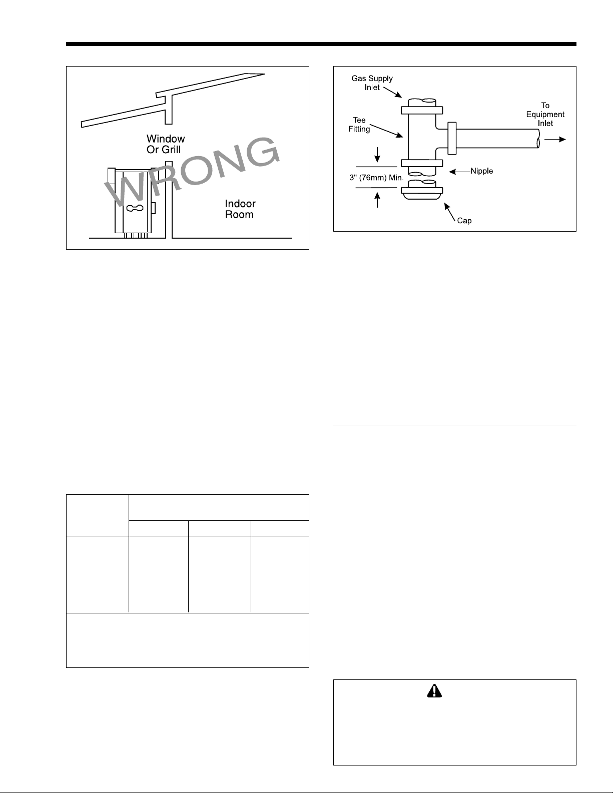
3. Never install the heater under any kind of roof
overhang. Do not place the heater below or
adjacent to any doors, windows, louvers, grills,
etc., which connect in any way with an inhabited
area of a building. This includes other structures
such as garages or utility rooms (see Figure 5).
4. Although the Laars models are CSA designed
certified for outdoor installations, such
installations are not recommended in areas where
the danger of freezing exists unless proper
precautions are taken for freeze protection.
Outdoor installations are not recommended in
areas where the danger of snow blockage exists.
Page 7
Mighty Therm Lo-NOx
Figure 5. Incorrect Outdoor Installation.
The heater should be located a safe distance
from Propane gas storage and filling equipment.
Consult local codes and fire protection authorities for
advice on specific installation restrictions.
2.4 Gas Supply and Piping
Review the following instructions before
proceeding with the installation.
1. Verify that the heater is fitted for the proper type
of gas by checking the rating plate. Laars heaters
are normally equipped to operate below a
2000 foot (609.6m) altitude. Heaters equipped to
operate at higher altitudes have appropriate
stickers or tags attached, also printed
information on rating plate.
2. Use the figures in Table 3 to provide adequate
gas piping from the gas meter to the heater.
Distance from Gas Meter
or Last Stage Regulator
Size 0-100' 100-200' 200-300'
500 1½" 2" 2"
715 2" 2" 2½"
999 2" 2½" 3"
1010 2" 2½" 3"
1200 2½" 3" 3"
1430 2½" 3" 3"
1825 2½" 3" 3½"
NOTE: These figures are for Natural Gas (.65 Sp. Gr.), and are
based on 1/2" water column pressure drop. Check supply
pressure with a manometer, and local code requirements for
variations. An average number of tees and elbows have been
taken into account.
Table 3. Gas Piping Sizes.
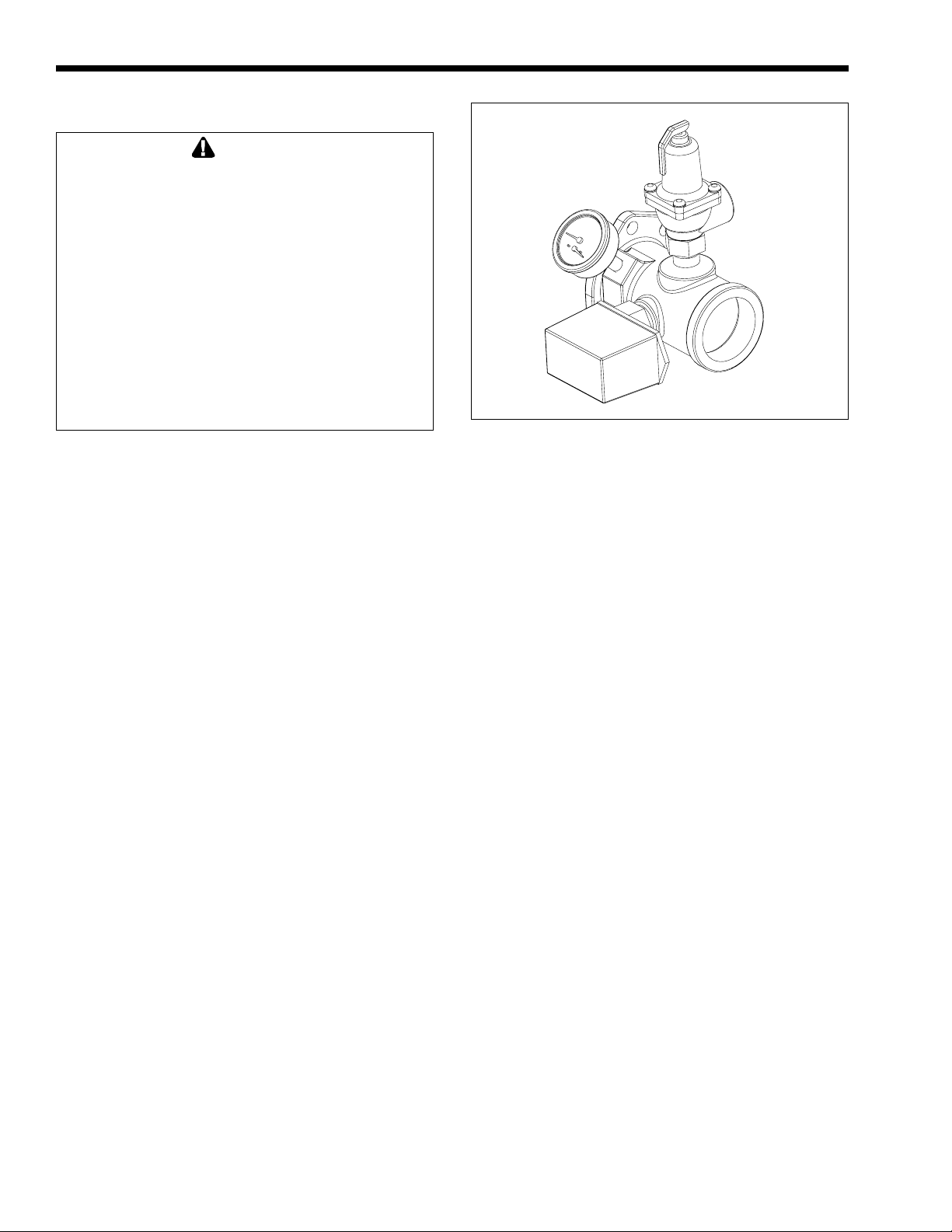
3. A sediment trap (drip leg) must be provided
ahead of the gas controls (see Figure 6). A
manual gas shutoff valve must also be provided
for service convenience and safety. A cap must
be provided for cleaning purposes. Check the
local codes.
Page 7
Figure 6. Sediment Trap Installation.
4. The heater and its individual shutoff valve must
be disconnected from the gas supply piping
system during any pressure testing of that system
at test pressures in excess of 1/2 psig. The heater
must be isolated from the gas supply piping
system by closing its individual manual gas
shutoff valve during any pressure testing of the
piping system at test pressures equal to or less
than 1/2 psig.
5. Provide gas supply pressure to the heater as
follows:
Natural
Gas
Max. (inches water column) 10
Min. (inches water column) 6.5
NOTE: the heater and all other gas appliances sharing
the boiler gas supply line must be firing at maximum
capacity to properly measure the inlet supply pressure.
Low gas pressure could be an indication of an
undersized gas meter and /or obstructed gas supply
line.
6. The correct burner manifold gas pressure is
stamped on the rating plate. The regulator is
preset at the factory and normally requires no
further adjustment.
7. The gas manifold and control assembly is
factory tested and conforms to the safe lighting
and other performance criteria specified in the
latest editions of ANSI Z21.13 and CGA 3.3
Low Pressure Boiler Standard.
8. Before operating the heater, test the complete
gas supply system and all connections for leaks
using a soap solution. Do not use raw flame.
Caution
Since some leak test solutions (including soap
and water) may cause corrosion or stress
cracking, the piping must be rinsed with water
after testing, unless it has been determined
that the leak test solution is noncorrosive.
Page 8
Page 8
2.5 Electrical Wiring
WARNING
The heater must be electrically grounded in
accordance with the most recent edition of the
National Electrical Code, ANSI/NFPA 70. In
Canada, all electrical wiring to the boiler should
be in accordance with the latest edition of CSA
C22.1 Canadian Electrical Code, Part 1. Do not
rely on the gas or water piping to ground the
metal parts of the boiler. Plastic pipe or
dielectric unions often isolate the heater
electrically. Service and maintenance
personnel who work on or around the heater
may be standing on wet floors and could be
electrocuted by an ungrounded heater.
Wiring diagrams are included in the information
packet provided with each unit.
1. All Laars heaters need 115V 60Hz supply
voltage unless specifically ordered otherwise.
Check heater wiring and pump for correct
voltage, frequency and phase. Consult the
National Electrical Code or the Canadian
Electrical Code regarding branch circuit
requirements for equipment with these motors.
2. The heater should be wired exactly as shown in
the wiring diagram.
3. All field installed electrical safety devices and
all field installed controllers (valve end switches,
draft switches, relays, timers) can be connected
to the heater control to the terminals shown in
the wiring diagram designated “Field Interlock.”
4. Where the heater is installed with a draft fan
refer to the fan manufacturer's wiring diagram.
The draft switch should be wired across the field
interlock terminals in the heater control panel.
SECTION 3.
Water Piping Instruction
3.1 General Piping Practice
1. Be sure to provide valves at the inlet and outlet
of the heater so it can be readily isolated for
service. A butterfly, ball type or similar type of
valve is recommended.
2. The pressure relief valve installed in the tapped
opening provided in the outlet header (see Figure
7), must be piped, but not fastened, to a drain or
floor sink. The drain pipe must be the same size
as the valve outlet and must pitch downward
from the valve. Pay special attention to relief
valve settings in installations where the heater is
located on the ground floor of a tall building, or
where the operating temperature of the heater is
LAARS HEATING SYSTEMS
Figure 7. Pressure Relief Valve Location.
above 210°F (99°C). In both instances, the static
pressure of the system is elevated and could
cause the relief valve to leak and bring
considerable raw water into the system.
3. Where no special setting of the relief valve is
ordered, the factory will furnish a 75 psi setting
for heating boilers (PH models), and 125 psi for
water heaters (PW models).
4. The pressure relief valve lever must be tripped at
least once a year to insure that waterways are
clean. When manually operating lever, water
will discharge through the drain line. Precautions
must be taken to avoid contact with hot water
and water damage.
3.2 Heating Boiler (PH Model)
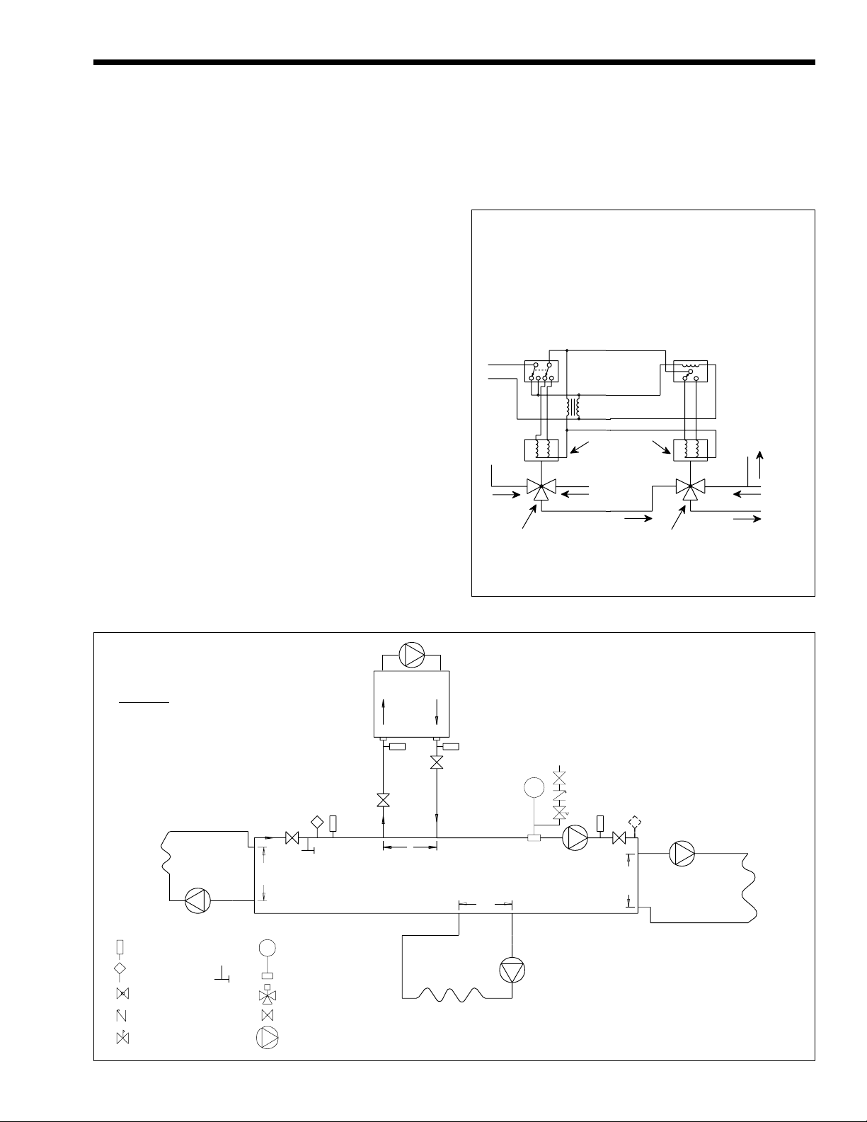
3.2.1 Variable Water Flow System
Heating systems using zone valves, zone pumps
or 3-way valves can experience reduced water flow
through the boiler. This can result in an excessive
water temperature rise and unstable boiler operation.
If the system water flow is variable, the boiler's
temperature sensor must be installed in the outlet
water. Laars recommends primary-secondary pumping
for all variable flow systems (see Figure 9). Primarysecondary pumping is mandatory for variable flow
systems. The boiler pump in a primary-secondary
system maintains constant flow through the boiler
even though the system flow is variable. In a primarysecondary system the pressure drop of the boiler is not
added to the system.
3.2.2 System Pressure Requirements
The boilers are designed to operate on closed,
pressurized systems. Maintain a minimum of 12 psi
(81.8 kPa) on the system where boiler supply water
temperature is 200°F (93°C) or less. If higher
temperatures are required, the minimum system
Page 9
Mighty Therm Lo-NOx
Page 9
pressure should be at least 15 psi (102.2 kPa) above
the water vapor pressure corresponding to the elevated
water temperature.
Heating boilers are not suitable for open systems
unless the supply water temperatures are kept below
180°F (82°C), and a minimum of 5 psi (34.1 kPa)
static head is maintained at the boiler.
3.2.3 Hot/Chilled Water Systems
When a boiler is connected to an air
conditioning system where the same water is used for
heating and cooling, you must prevent chilled water
from entering the boiler When changing such a system
from cooling to heating, allow the chilled water to
circulate through the building, after the chiller has
been turned off, for a period long enough for the water
to warm up to at least 105°F (41°C) before the water
flows into the boiler. It is equally important to prevent
hot water from entering the chiller. The system shown
in Figure 8 is suggested to make sure the system water
is neither too hot nor too cold when a changeover
takes place. When a boiler is connected to heating
coils located in air handling units (where they may be
exposed to refrigerated air circulation), install a flow
control valve or other automatic means to prevent
gravity circulation of chilled water through the boiler.
Chilled water in the boiler will create condensate on
the boiler tubes. Boilers installed in violation of the
foregoing may void the warranty.
3.2.4 Combined Space Heating/Potable
Water Heating Systems
When using the Laars boiler as a source of heat
for a combined space heating/potable water heating
system, be sure to follow the instructions of the space
heating system.
Suggested Wiring Diagram For
Tempering System Water at
Changeover From Heating To Cooling
DPDT Manual or Automatic
Change-Over Switch
DPDT - Set at Change-Over
Temperature
115/24V
Transformer
From
Chiller
3-Way Valve No. 1
Change-Over
(Heating and Cooling)
Valve Motors
2-Pos
3-Wire - 24V
From
Boiler
3-Way Valve No. 2
To By-Pass
Both Heater and
Chiller
Clock Timer
Auto-Resetting
Set at 15 Minute SPDT
To Boiler
and
Chiller
By-Pass
From
System
To
System
WARNING: This drawing shows suggested
piping configuration and valving. Check with
local codes and ordinances for additional
requirements.
12"
Max.
LEGEND:
Thermometer
Temperature
Sensor
Globe Valve
Check V alve
Pressure Reducing Valve
w/Fast Fill Bypass
Purge
Valve
Expansion T ank
with Air Scoop and
Auto Air Vent
3-Wa y Valve
Valve
Pump
12"
Max.
Figure 8. Boiler-Chiller Installation.
Boiler Circulation
Pump
Cold Water
Make-Up
System Pump
12"
12"
Max.
Boiler circuit piping must be equal to or larger than
boiler water connection size.
Boiler circulation pump sized for flow through
boiler.
Dotted devices indicate alternate locations.
Max.
Figure 9. Primary-Secondary Plumbing.
Page 10

Page 10
LAARS HEATING SYSTEMS
Do not use water piping, fittings, valves, pumps,
and any other components which are not compatible
with potable water.
Do not connect the heater, which will be used to
supply potable water, to any heating system or
components previously used with a nonpotable water
heating system.
Do not add boiler treatment or any chemicals to
the heating system piping, since the piping contains
water for potable use.
Do not use solder containing lead in the potable
water lines.
Some jurisdictions may require a backflow
preventer in the cold water line. In such cases,
pressure relief valve may discharge water due to
expansion. An expansion tank approved for potable
water will eliminate this condition. Follow the
manufacturer's instructions for installation of the
expansion tank.
3.2.5 Piping System Requirements
1. Provide a boiler installed above radiation level
with a low water cutoff device either as part of
the boiler or at the time of boiler installation.
2. Install manual and/or automatic bleeding devices
at high points in the system to eliminate air.
Install a correctly sized expansion or
compression tank with suitable air charger and
tank drainer, as appropriate.
3. Support the weight of all water and gas piping by
suitable hangers or floor stands.
4. Check piping diagrams with local applicable
plumbing, heating and building safety codes.
3.2.6 Filling The System
1. Ensure the system is fully connected. Close all
bleeding devices and open make-up water valve.
Allow system to fill slowly.
2. If make-up water pump is employed, adjust
pressure switch on pumping system to provide a
minimum of 12 psi (81.8 kPa) at the highest
point in the heating loop.
3. If a water pressure regulator is provided on the
make-up water line, adjust the pressure regulator
to provide at least 12 psi (81.8 kPa) at the
highest point in the heating loop.
4. Open bleeding devices on all radiation units at
the high points in the piping throughout the
system, unless automatic air bleeders are
provided at such points.
5. Run system circulating pump and boiler pump
for a minimum of 30 minutes with the boiler gas
shut off.
6. Open all strainers in the circulating system,
check flow switch operation, and check for
debris.
7. Recheck all air bleeders as described in Step 4
above.
8. Check liquid level in expansion tank. With the
system full of water and under normal operating
pressure, the level of water in the expansion tank
should not exceed 1/4 of the total, with the
balance filled with air.
9. Start up boiler according to procedure described
in Section 4. Operate the entire system,
including the pump, boiler, and radiation units
for one (1) hour.
10. Recheck the water level in the expansion tank. If
the water level exceeds 1/4 of the volume of the
expansion tank, open the tank drainer and drain
to that level.
11. Shut down the entire system and vent all
radiation units and high points in the system
piping as described in Step 4 above.
12. Close make-up water valve and check strainer in
pressure reducing valve for sediment or debris
from the make-up water line. Reopen make-up
water valve.
13. Check gauge for correct water pressure and also
check water level in system. If the height
indicated above the boiler insures that water is at
the highest point in the circulating loop, then the
system is ready for operation.
14. Within three (3) days of start-up, recheck all air
bleeders and expansion tank as described in
Steps 4 and 8 above.
3.3 Water Heater (PW Model)
3.3.1 Water Chemistry
Laars equipment is designed for use in a wide
variety of water conditions. The water velocity
maintained in the heat exchanger tubes is kept high
enough to prevent scaling from hard water and low
enough to avoid corrosion from soft water. Ninetyfive percent of the urban areas in the country have
water that is compatible with this equipment, but in
some areas a water supply will contain a large
quantity of scaling chemicals or the water may be
extremely soft and corrosive. In rare situations the
water will contain both scaling chemicals and
corrosive chemicals such as calcium or sodium
chloride. These conditions may be the result of a
nearby well or pumping station and the particular
condition may not be characteristic of the entire city
water system.
If an installer observes damage from these
conditions to any water handling equipment in the
area, a factory representative should be contacted
immediately for assistance in minimizing maintenance
costs. If erosion is present, the pump impeller can be
replaced to reduce water velocity. If scaling
conditions are bad, tube cleaning maintenance
schedules can be established to prevent tube burn-out
and cracking. Neglecting the problem could mean
serious damage to the heater and water system.
Scaling can be recognized as a layer deposited
Page 11
Mighty Therm Lo-NOx
Page 11
on the inner walls of the tube which reduces the inner
diameter of the tube. Scale can be any color or
texture; smooth or rough, granular or amorphous.
Signs of erosion are generally pitting, cavitation,
ridges and “islands” on the inner walls of the tubes.
Since this condition results from extremely soft water
sources, or as a result of a water softening program,
the internal copper surfaces will be extremely shiny.
Other chemicals, such as chlorine or chlorides in the
water, will cause dark surfaces of erosion.
In areas where the water supply is extremely
corrosive, it is advisable to order the heater with
cupro-nickel tubes in the exchanger.
Damage From Scaling, Corrosion, or Erosion
is Not Covered by the Warranty.
3.3.2 Piping System Requirements
1. Check piping diagrams with local applicable
plumbing, heating and building safety codes.
2. All two-temperature systems using temperature
valves must have forced recirculation in the low
temperature building loop.
3. A check valve installed at the hot water inlet to
the tempering valve will prevent cold water from
being drawn in reverse through the tempering
valve into the hot water.
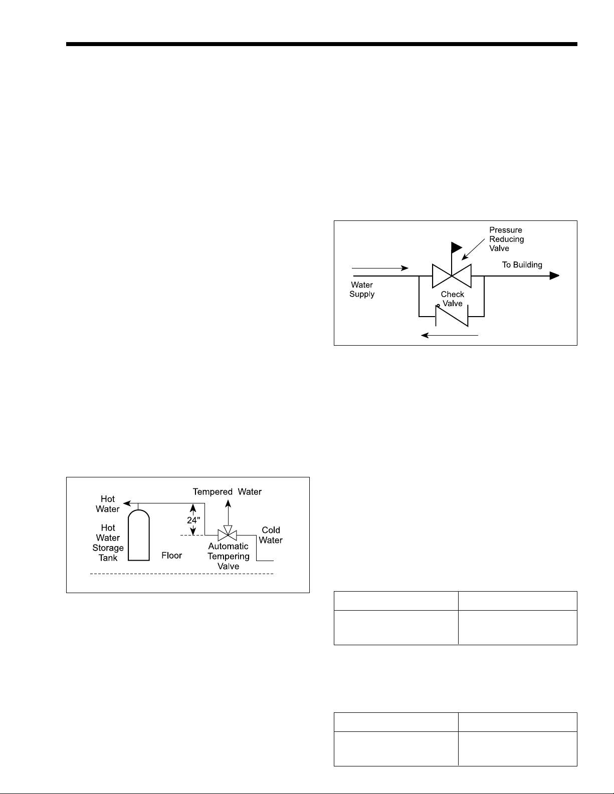
4. When installing a tempering valve, place at
bottom of antithermosyphon loop at least 24"
high to prevent excessive hot water from
entering mixed water supply. Bring the cold
water supply up from the floor to the valve (see
Figure 10).
The following suggestions may solve the
problem:
1. Replace the installed water pressure reducing
valve with a suitable valve having a back flow
port. These valves have a back flow port which
allows water to flow backwards when the
pressure in the system exceeds the pressure in
the mains.
2. Install a check valve around the pressure
reducing valve to permit reverse flow. This will
allow the expanded water to back flow into the
mains (see Figure 11).
Figure 11. Check Valve/Pressure Reducing Valve
Installation.
3. Install an auxiliary small relief valve set at 25 psi
less than the main relief valve. The valve must
be piped to a drain and may require occasional
cleaning. It will bleed off the expanded water
and protect the main pressure relief valve from
becoming fouled.
4. Install a properly sized expansion tank.
Figure 10. Tempering Valve Installation.
3.3.3 Water Expansion
When cold water is heated the water expands. If
no water is being used during the heat-up period the
expanded water will normally back up into the city
mains.
A water pressure reducing valve installed in the
incoming cold water line may act as a check valve and
prevent the expanded water from moving backward.
This will cause pressure to rise in the heater, which
will be relieved by the pressure relief valve.
If the relief valve pops frequently a mineral
deposit may build up on the valve seat, causing it to
leak.
3.3.4 Pump Requirements
1. The factory provided pump on PW heaters are
sized to provide proper circulation through the
heater and heater-to-tank circulation loop (see
Figures 12, 13 and 14). If the heater-to-tank
circulation loop does not contain more than 6
elbows and 30 feet of pipe, use pipe fittings in
the loop no smaller than the following:
Model Pipe Size
500 through 715 2"
999 through 1825 2-1/2"
If the heater-to-tank circulating loop contains
more than 6 elbows and 30 feet of pipe, use
pipe or fittings in the loop no smaller than the
following:
Model Pipe Size
500 through 715 2-1/2"
999 through 1825 3"
Page 12

Page 12
LAARS HEATING SYSTEMS
Figure 12. Hot Water Supply System with Vertical Tank.
NOTES:
Heavy line indicates Heater to Tank Circulating Loop.
Figure 13. Hot Water Supply System with Horizontal Tank.
NOTES:
Heavy line indicates Heater to Tank Circulating Loop.
Page 13

Mighty Therm Lo-NOx
Page 13
Figure 14. Hot Water Supply System Using Dual Tanks.
2. Model PW heater is not suitable for heating
swimming pools or any other application where
temperature of the water flowing through the
heater remains below the dew point (110°F).
In applications requiring the rapid use of
measured volumes of water, the recovery of the
heater between the time intervals of use must
equal the volume used. See the recovery table in
the current Document 2129 (Submittal Data).
3. Pump Sizing: the heater circulating pump is
sized to provide enough flow to prevent damage
to the heat exchanger. Specifications in Table 4
include allowance for 30 feet of piping and 6
elbows between heater and tank.
IMPORTANT: Check oil level in pump before
starting. Oil pump every three (3) months. Fill
bearing assembly to lower level of overflow
vent. Add five (5) or six (6) drops of oil to front
and rear of motor. Use 20W non-detergent oil.
Pumps located in excessively hot or dusty
locations should be oiled once a month. Self
lubricating pumps do not require oiling.
4. The pump should be accessible for lubrication,
inspection and service.
NOTES:
1. Heavy line indicates Heater to Tank Circulating Loop.
2. When a very large volume of water is circulated in the building
loop with the use of a separate pump, tee building loop into cold
water supply and return to storage tank.
Flow Head* Temp. Rise
Water Rate Loss Across
Model Category (GPM) (ft.) Heater, (°F)
500 Normal 68 9.9 11
715 Normal 68 11.0 16
999 Soft 45 3.9 35
and Normal 68 7.5 23
1010 Hard 90 11.7 18
1200 Normal 68 7.8 27
1430 Normal 68 8.1 32
1825 Normal** 90 13.5 30
Water Category Grain Hardness per Gal.
Soft 1 through 7.5
Normal 7.6 through 17
Hard Over 17
* Pressure drop includes loss through 30 feet of pipe and normal fittings when
heater is installed with storage tank. Pipe and fittings are assumed to be 2" on
Models (500-715) and 2 1/2" on Models (1010-1825)
** To prevent erosion, these models must be ordered with cupro-nickel heat
exchanger tubes.
Soft 45 5.0 17
Hard 90 15.7 8
Soft 45 5.3 24
Hard 90 17.8 12
Soft 68 7.8 27
Hard 90 12.2 21
Soft** 68 8 . 1 32
Hard 90 12.6 24
Soft** 90 13.5 30
Hard 90 13.5 30
Table 4. Pump Performance Requirements.
Page 14

Page 14
LAARS HEATING SYSTEMS
3.3.5 Water Pressure
It is very important that water pressure in the
system be maintained above 30 psi. If the system
pressure should drop below this, the vapor pressure of
water in the suction side of the pump can cause
hammer and cavitation in the pump and damage the
heater through lack of water circulation.
For protection against excessive pressure the
water heater is equipped with a pressure relief valve.
When the water heater is connected to a separate
storage vessel, a temperature and pressure relief valve
must be installed on the storage vessel. The
temperature and pressure relief valve must be designcertified in accordance with the requirements for
Relief Valves and Automatic Gas Shutoff Devices for
Hot Water Supply Systems, ANSI Z21.22. (in Canada,
in accordance with the requirements for the Standard
for Temperature and Pressure Relief Valves and
Vacuum Relief Valves, CAN1-4.4).
The temperature and pressure relief valve must
have a BTU/h (kW/h) capacity rating that is greater
than the BTU/h (kW/h) input of the water heater. The
temperature and pressure relief valve must be marked
with a maximum working pressure not to exceed the
maximum working pressure shown on the rating plate
of the water heater, or the maximum working pressure
of the separate storage vessel, whichever is the lower
pressure. The temperature and pressure relief valve
must have a maximum working temperature not to
exceed 210°F (99°C).
Do not place any shutoff valves between the
temperature and pressure relief valve and the storage
vessel.
The relief valves discharge water in large
quantities should circumstances demand.
3.3.6 Tank Installation
1. Be sure the floor is waterproof and structurally
capable of supporting the tank when it is filled
with water.
2. The tank should be placed so that manholes,
inspection covers, nameplates and drain valves
are accessible.
3. Be sure the tank is suitable for the water in the
system. Some water is corrosive and requires a
protected tank with a special lining.
4. If the tank is glass-lined, it should be equipped
with a suitable magnesium anode. It is good
practice to replace the anode when it is
approximately 50% used. The factory warranty
on a glass-lined tank, if provided, will be void if
a satisfactory anode is not in place at the time of
a failure or if it is consumed by cathodic action.
5. Make sure the tank connections in the heatertank circulating loop are the proper size as listed
in Section 3.3.4. If tappings are smaller than the
recommended pipe size, a larger pump may be
required. Consult the factory if in doubt.
6. Install a pipe in the tank drain fitting that goes to
a floor sink, and install a drain valve. If a floor
sink is not available, install a hose bib.
3.3.7 Two-Temperature System
See Figures 15 and 16 for piping schematics.
This system is designed to maintain the tempered
water circulating loop at the desired temperature
Figure 15. Two Temperature Hot Water Supply system with Horizontal Tank.
Legend
Check V alve
T empering Valve
Venturi (Suction) Te e
Throttling Valves / Service Valves
Page 15

Mighty Therm Lo-NOx
Page 15
Legend
Check Valve
T empering Valve
Venturi (Suction) Te e
Throttling Valves / Service Valves
Figure 16. Two Temperature Hot Water Supply System with Vertical Tank.
during idle periods as well as when there is a demand
for hot water. It is recommended for general purpose
water supply including shower and bathing
applications. Water at 180°F is available directly from
the tank.
WARNING
Hot water can scald! Hot water can produce
third degree burns in 6 seconds at 140°F
(60°C) and in 30 seconds at 130°F (54°C).
VAC establishing the flame at the burner(s). The
control then switches to the sensing mode to monitor
the flame presence. The unit performs its own safety
check during trial for ignition period and if the flame
is not established, the control interrupts the power to
the main gas valve(s) and goes into lockout.
4.1.2 Hot Surface Igniter
This is a 120 VAC, silicon carbide igniter.
During ignition cycle the igniter will glow for a few
seconds until reaching the proper ignition temperature
to ignite the gas at the burner ports.
SECTION 4.
Operating Instructions
4.1.3 Combustion Air Pressure Switch
The diaphragm type air pressure switch is
provided to prove the combustion air flow required for
proper combustion. Tube connection is attached to the
4.1 Controls - General
positive barbed end.
(See Figures 17 and 18)
4.1.1 Electronic Ignition Control
This is a proved hot surface ignition control. It
combines a hot surface igniter and a flame sensor.
Upon a call for heat, the igniter is energized from a
nominal 120 VAC and is proven to be capable of
ignition. The gas valve(s) is then powered with 24
4.1.4 Operating Controls
Single or two-stage aquastats are provided in
models PH and PW heaters to control the desired
service water temperature. The temperature sensing
bulb is located either in the boiler inlet or outlet
header.
Page 16

Page 16
LAARS HEATING SYSTEMS
NOTE: Indoor unit shown. Outdoor unit, door must be removed to access controls.
Figure 17. Controls Location.
Figure 18. Operating and Safety Components.
4.1.5 High Limit Control
The manual reset high limit switches are
provided as standard equipment on all heaters.
Automatic reset switches are optionally provided. The
4.1.7 Low Water Cut Off
The low water cut off automatically shuts off the
heater whenever water level drops below probe. The
probe is located at the heater water inlet header.
temperature sensing bulb of the switch is always
located in the heater outlet. Burners will automatically
4.2 Start-Up Requirements
shut down whenever overheating of water occurs
(exceeding the temperature set point of the switch).
Do not use this appliance if any part has been
4.1.6 Flow Switch
Standard on all models: The switch is mounted
in the outlet “tee” connection. The flow switch shuts
down all burners in case of pump failure and/or
reduced water flow.
under water. Immediately call a qualified
service technician to inspect the heater. The
possible damage to a flooded appliance can be
extensive and present numerous safety
hazards. Any appliance that has been under
water must be replaced.
WARNING
Page 17

Mighty Therm Lo-NOx
Page 17
NOTE: Safe lighting and other performance
criteria were met with the gas manifold and control
assembly provided on the heater when it underwent
tests specified in ANSI Z21.13 and CAN1-4.3-M85.
Before placing the heater in operation, check the
automatic safety shutoff devices. Once the heater is
connected to the gas piping and after all of the
requirements in Sections 2 and 3 have been met,
follow these procedures:
1. Before beginning the tests, make sure the main
manual gas valve, and any other heater firing
valves, are in the OFF position. The heater's gas
valve is turned OFF as follows:
a. Sizes 500 and 715: Turn the gas control
knob clockwise to OFF.
b. Sizes 1010 through 1825: Manual gas valve
is OFF when handle is at right angle to the
gas pipe (see Figure 19).
2. The ignition control turns on the combustion
blower. After about a 15 second pre-ignition
purge, while the blower clears the combustion
chamber, the igniter is turned on. The igniter
takes about 25 seconds to heat up. A glow can be
seen through the view port (see Figure 17).
3. The manual gas valve must be ON for the burner
to ignite. This valve is turned ON as follows:
a. Size 500 and 715: Turn counterclockwise
to ON (see Figure 19).
b. Sizes 1010 through 1825: Valve is ON
when handle is parallel to the gas pipe (see
Figure 19).
4.4 Hi-Limit Checkout
After running the boiler for a long enough period
to bring the water temperature within the range of the
hi-limit, slowly back off the high limit setting until the
boiler shuts off. The main burners should re-ignite
when the hi-limit is turned back up to its original
setting and the hi-limit is reset.
4.5 Start-Up Procedure
(See Section 4.2 for Startup
Requirements)
Figure 19. Handle Position of Gas Valves.
2. Before placing the heater in operation, be certain
that the heater is filled with water and all air is
purged from the system.
3. Make sure the power switch on the heater is in
the ON position. Reset all safety devices (hilimit, switch, low water cutoff, etc.).
4.3 Normal Operating Sequence
When the circulation pump is running, the heater
will turn itself on and off via the temperature control.
When the water temperature drops below the
differential setting, below the set point, the following
sequence happens:
1. The temperature control (aquastat) powers the
ignition control.
WARNING
If you do not follow these instructions exactly, a
fire or explosion may result causing property
damage, personal injury or loss of life.
1. This appliance does not have a pilot. It is
equipped with an ignition device which
automatically lights the burner. Do
light the burner by hand.
2. BEFORE OPERATING, smell all around the
appliance area for gas. Be sure to smell next to
the floor because some gas is heavier than air
and will settle to the floor.
WHAT TO DO IF YOU SMELL GAS
a. Do not try to light any appliance.
b. Do not touch any electric switch; do not
use any phone in your building.
c. Immediately call your gas supplier from a
neighbor's phone. Follow the gas supplier's
instructions.
d. If you cannot reach your gas supplier, call
the fire department.
3. Use only your hand to push in or turn the gas
control knob. Never use tools. If the knob will
not push in or turn by hand, don't try to repair it,
call a qualified service technician. Force or
attempted repair may result in a fire or
explosion.
not try to
Page 18

Page 18
LAARS HEATING SYSTEMS
4. Do not use this appliance if any part has been
under water. Immediately call a qualified service
technician to inspect the appliance and to replace
the heater.
4.5.1 Lighting Instructions
1. STOP! Read the safety information (1 through 4)
above.
2. Turn off all electric power to the appliance.
3. Remove control access panel.
4. Set the thermostat or aquastat to lowest setting.
5. This appliance is equipped with an ignition
device which automatically lights the burner. Do
not try to light the burner by hand.
6. Turn off manual gas valve. Valve is off when
valve handle is at right angle to the gas pipe. On
combination valves (size 500 and 715) turn gas
control knob clockwise
Figure 19).
7. Wait five (5) minutes to clear out any gas. Then
smell for gas, including near the floor. If you
smell gas, STOP! Follow the safety information
titled “Before Operating”. If you don't smell gas,
go to next step.
8. Turn gas control knob counterclockwise
to ON.
9. Set thermostat or aquastat to desired setting.
10. Replace control access panel.
11. Turn on all electric power to the appliance.
12. If the appliance will not operate, follow the
instructions “To Turn Off Gas To Appliance”
and call your service technician or gas supplier.
4.5.2 To Turn Off Gas to Appliance
1. Turn off all electric power to the appliance if
service is to be performed.
2. Remove control access panel.
3. Set the thermostat or aquastat to lowest setting.
4. Turn the gas control knob clockwise
Do not force.
5. Replace control access panel.
to OFF position (see
to OFF.
4.6 Setting the Temperature Controls
4.6.1 Hydronic Boilers
To set the temperature and high-limit controls:
1. Set the temperature controller at the system
design temperature.
2. Set the high-limit 40°F to 50°F above
temperature controller setting.
4.6.2 Water Heaters
The hi-limit switch is factory set and should not
be adjusted.
WARNING
Adjusting the temperature control past the
recommended setting can result in a scalding
injury. Hot water can produce third degree
burns in 6 seconds at 140°F (60°C) and in 30
seconds at 130°F (54°C).
Water temperature can be adjusted at the
temperature control. The temperature control is
adjusted to its lowest setting when it is shipped from
the factory. The 130°F (54°C) setting is the
recommended starting point for setting the
temperature control. Make sure that the hi-limit switch
is set 30°F (17°C) higher than the temperature control.
The recommended setting will result in
satisfactory energy savings. Lowering the temperature
may result in reduced energy costs. Connecting the
heater to a separate storage vessel and lowering the
temperature setting, may reduce energy losses during
standby periods when hot water is not being used, and
may meet normal hot water needs. For increased hot
water usage, a higher temperature setting may be
necessary to meet increased demand. Reset the
temperature setting to a lower level after periods of
increased usage are over.
SECTION 5.
Maintenance
Caution
Label all wires prior to disconnection when
servicing controls. Wiring errors can cause
improper and dangerous operation.
5.1 General Instructions
1. Oil the water circulating pump in accordance
with the manufacturer's instructions.
2. Oil the combustion air blower motor bearings
every 6 months.
3. If a strainer is used in a pressure reducing valve
or in the piping, clean it every 6 months in
accordance with the manufacturer's instructions.
Page 19

Mighty Therm Lo-NOx
4. At startup and every 6 months after, using the
burners view port, look at the burner flame for
proper performance. The burner should not
require maintenance in normal operation. If any
malfunction indicates that the burner needs
service (e.g., a flame that is yellow, or entire
burner surface glowing red), call a professional
service technician. The flame should be checked
for the following:
a. Normal Flame: Blue flame color, with
slight yellow tips, with a well-defined inner
cone.
b. Yellow Flames: Can be caused by blockage
of primary air flow to the burner(s) or
excessive gas input. This condition MUST
be corrected immediately.
c. Lifting Flames: Lifting flames can be
caused by over firing the burner(s) or
excessive primary air.
5. Inspect the venting system for blockage, leakage,
and corrosion at least once a year.
6. Keep the heater area clear of combustible
material, gasoline, and other flammable liquids
and vapors.
7. Be sure all combustion air and ventilation
openings are not blocked.
5.2 Combustion Air Blower
This heater uses a fan assisted combustion
process. For proper operation of the burners, inspect
the air blower for contamination one week after startup and every three (3) months thereafter. Blower
housing inlet must be completely isolated and
protected from any source of corrosive chemical
fumes, and from exhaust vents of cleaning equipment
or laundry establishments.
1. To inspect and service the blower, shut off all
electrical and gas supply to the heater.
2. Remove the screws holding the blower housing
cover to expose the blower (see Figure 20).
3. Remove filter and clean any contamination or
debris (see Figure 20).
4. Remove the air orifice off the blower inlet to
inspect the blower wheel. Clean the blower
housing and its wheel from any contamination or
debris.
5. Remove manifold compartment cover, inspect
the compartment and around the gas manifold
for lint or any other form of debris. If required,
vacuum out all contamination.
6. Replace all parts securely in place.
Page 19
Figure 20. Blower-Housing.
5.3 Heat Exchanger
Check for fouling on the external surfaces of the
heat exchanger every six months. (NOTE: After
installation and first start-up, check the heat
exchanger for fouling after the following periods of
operation: 24 hours, 7 days, 30 days, 90 days, and
once every six months thereafter).
WARNING
Improper installation or maintenance can
cause nausea or asphyxiation from carbon
monoxide in flue gases which could result in
severe injury, property damage, or death.
Fouling on the external surfaces of the heat
exchanger is caused by incomplete combustion and is
a sign of combustion air and/or venting problems. As
soon as any fouling is observed, the cause of the
fouling should be corrected. The heat exchanger can
be checked by removing the venting and top panel as
necessary to inspect from above. Also check the vent
system for defects at this time.
5.3.1 External Cleaning of Heat
Exchanger
1. If cleaning is required, disconnect electrical
supply to the heater and remove wires and
conduit from the heater’s pump.
2. Turn off the gas supply by closing the manual
gas valve on the heater.
3. Isolate the heat exchanger from water supply.
4. Remove the vent pipe (for outdoor units remove
vent top assembly), top panel, upper jacket
assembly and flue collector (see Figures 22 and
28).
5. Drain the heat exchanger.
Page 20

Page 20
LAARS HEATING SYSTEMS
6. Disconnect the flange and the adapter tee from
the heat exchanger inlet and outlet.
7. Remove temperature-sensing probes from inlet
and outlet header.
8. Remove the heat exchanger from the heater. The
heat exchangers are heavy and require
minimum two people to remove to avoid
personal injury
9. Remove the tube’s baffles from the heat
exchanger.
Caution
Black carbon soot buildup on a dirty heat
exchanger can be ignited by a random spark or
flame. To prevent this from happening, dampen
the soot deposits with a wet brush or fine water
spray before servicing the heat exchanger.
10. Clean the heat exchanger: A light accumulation
of soot or corrosion on the outside of the heat
exchanger can be easily removed after the heat
baffles are removed. Use a wire brush to remove
loose soot and scale from the heat exchanger. Do
not use water or compressed air for cleaning.
NOTE: While the heat exchanger is out of the
heater, inspect the firewall refractory blocks for
cracks, wear and breakage. Replace if necessary.
11. Reassemble in reverse order and be sure the heat
exchanger baffles are replaced.
3. Air pressure proving switch(es).
4. Automatic electric and manual gas valve(s).
5. Water flow sensing safety device.
6. Low water cutoffs (every six months).
5.5 Burner Removal and Cleaning
1. Disconnect electrical supply to the heater.
2. Turn off main manual gas valve on the heater.
3. Remove the cover of air mixture plenum.
4. Disconnect air tube(s) from air mixture plenum
barb(s), and remove wires from igniter and flame
sensor.
5. Disconnect gas valve train from the gas manifold.
6. Remove screws from manifold mounting
brackets. Pull manifold/orifice assembly away
from the burner panel.
7. Remove screws attaching air mixture plenum to
the side air duct(s) and to the burner panel, and
then slide away the mixture plenum.
8. Remove burner panel off the front lower jacket.
9. Disconnect burners from panel by removing
mounting screws from each burner. Use caution
to prevent damage to burner gaskets, insulation
blanket, hot surface igniter or flame sensor.
10. Clean soot and any debris from burners with a
stiff bristle brush. Damaged burners or burner
gaskets must be replaced.
5.3.2 Internal Cleaning of Heat Exchanger
1. To remove the heat exchanger, follow the
procedure detailed in 5.3.2 (1 through 8).
2. Remove the inlet/outlet header of the heat
exchanger.
3. Remove the return cover of the heat exchanger.
4. Clean the internal surface. (Laars offers a tube
cleaning kit part no. R00100000.)
5. Reassemble in the reverse order.
5.4 Gas and Electric Controls
The gas and electric controls on the heaters are
designed for both dependable operation and long life.
Safe operation of the heater depends on their proper
functioning. A professional service technician should
check the following basic items every year, and
replace when necessary.
NOTE: the warranty does not cover damage
caused by lack of required maintenance or improper
operating practices.
1. Water temperature controls.
2. Ignition control system.
SECTION 6.
Troubleshooting
6.1 Sequence of Operation
To troubleshoot the heater properly you must first
understand the sequence of operation of the heater:
1. Upon a call for heat a 24 VAC signal is sent
through fusible links and high limit(s) to the
ignition control “H” terminal.
2. The “IND” terminal of the ignition control is
energized with 115 VAC for a (15) second preignition purge period during which the combustion blower purges the combustion chamber.
3. After the purge period, terminal “S1” is
energized with 115 VAC for (20 to 35) second
igniter heat up period. The glow of the igniter
can be seen through the heater view port.
4. Then there is a seven second trial for ignition.
During this time the gas valves are energized
with 24 VAC, and the main burner ignites. The
gas valves will remain energized throughout the
call for heat as long as the ignition control flame
sensor senses a stable flame.
Page 21

Mighty Therm Lo-NOx
Page 21
5. After the call for heat is satisfied the ignition
control closes the gas valves and operates the
blower for a thirty (30) second post purge cycle.
This clears the combustion chamber of
combustion products.
The ignition is attempted one time. If ignition is
not successful, the control shuts down and “locks
out.” It remains in the lockout condition until the
lockout reset button on the ignition control is reset.
6.2 Electrical Components
This section describes guidelines for checking
the operation of electrical components installed on the
heater. Refer to the wiring diagram for correct
connection locations.
6.2.1 General Troubleshooting
This section describes guidelines for checking
the electrical components of the heater. Experience
has shown that most complaints about heaters failing
to fire have nothing to do with the heater itself.
Usually, one of the protective switches in the heater
system has shut down operation.
Any of the following can prevent proper
operation. Check these items first:
1. Be sure the heater has been properly installed
(see Section 2 and 3).
2. Make sure the pump is not airlocked, clogged or
otherwise inoperative.
3. Make sure the gas valve is on and there is
sufficient gas pressure in the line. All external
gas valves must be open.
Caution
The ignition control and igniter operate on
115VAC power. Keep this in mind while
servicing the heater, and take care to avoid
electrical shock.
4. Verify that the electrical circuit serving the
heater is ON.
5. Make sure the toggle switch on the right side of
the heater is ON.
6. Check the fuse inside the black, twist-lock fuse
holder. If it is burned, replace it.
7. With the power off inspect all electrical connections and wiring. Finding a loose connection or
charred wire can save a lot of time and money.
8. Make sure the temperature controller is set high
enough to call for heat.
9. Make sure none of the manual reset controls, i.e.,
low water cutoff, high limit, etc., have tripped.
Reset any tripped switches.
If the pump is circulating water and the
foregoing items check out okay, the trouble may be in
the heater control system.
IMPORTANT: Disconnect power to the heater
before removing or replacing any component or wire
connection. If the power is not disconnected, “jumping”
the gas valve or accidentally grounding the wire harness
or component terminals to the heater frame or jacket
could cause the ignition control fuse to blow.
6.2.2 Electrical Troubleshooting
Troubleshooting procedures should only be
performed by professional service technicians
qualified in heater maintenance.
Some electrical components are wired in
parallel, so it is necessary to troubleshoot in the order
that they appear on the wiring diagram or the
troubleshooting flow chart (see Figure 21).
The following steps should be used when
troubleshooting the heater:
1. Remove the control panel cover of heater.
2. Turn the manual gas valve on the heater off.
3. If the heater has locked out turn the toggle
switch off for 5 seconds then back on to reset the
heater.
4. Use the troubleshooting flow chart (see Figure
21) to determine what components and wiring
should be tested first.
5. Test each component by checking for 24 VAC or
115 VAC entering and exiting the device. If
there is voltage entering the safety device, but
none leaving then there is an open circuit and it
must be determined why it is open. When testing
components between “MV ” of the ignition
control and the gas valve install a meter and let
the heater cycle through one complete sequence
of operation. During the sequence of operation
these safeties will only be energized for the
seven second trial for ignition.
6. Turn the manual gas valve of the heater on and
fire the heater.
Caution
Label all wires prior to disconnection when
servicing controls. Wiring errors can cause
improper and dangerous operation. Verify
proper operation after servicing.
Page 22

Page 22
LAARS HEATING SYSTEMS
Figure 21. Troubleshooting Chart.
Page 23

Mighty Therm Lo-NOx
Page 23
6.3 Mechanical Components
6.3.1 Pressure Relief Valves Leaking Intermittently or Steadily
Possible Cause Remedy
A. Static pressure in system exceeds A. Calculate height of water in system above heater. Install
setting of relief valve. new valve with psi setting 25% above required static system
working pressure. Do not exceed 160 psi.
B. Expansion tank is waterlogged B. Drain expansion tank, then reopen it to the system. Look
(if installed). for leaks in expansion tank or fittings. Calculate required
volume of expansion tank in relation to system to
determine that tank is adequate.
6.3.2 Heater is Pounding, Knocking or Emitting Steam from Relief Valves
A. Low or no water flow. A. This condition is usually caused by lack of adequate water
flow through heater. Check the following:
1. Is the heater wired into the pump circuit so that the heater
cannot fire unless the pump is running?
2. Check to see that all valves in system are open to be sure
that water can circulate through the heater and the system.
3. If the system has automatic water valves (2-way or 3-way)
that can cut off the water flow through the heater, check to
see that they are equipped with end-switches which shut the
heater down when the water flow through the heater is
reduced by 70% from full flow
4. Examine pump for clogged impeller.
B. Low or no system pressure. B. Clean strainer in pressure reducing valve. Look for closed
valve water line or a leak in the system.
C. Clogged “Y” strainer. C. Remove strainer element and clean screen.
D. Debris from system piping is D. Remove header covers. Examine all tubes and waterways.
blocking tubes. Use new gaskets when reassembling. Clean out tubes.
E. Scale has formed in tubes. E. PH - Check for inflow of raw water (is due to system leak).
See Section 3.2.
PW - Water chemistry or flow problems, see Section 3.3.
6.3.3 Soot in Flueways or in Tubes, or Noxious Fumes Indicative of Bad Combustion
A. Combustion air supply to heater A. Check air supply opening. Look for debris in screen or
room is inadequate. louvre which covers combustion air opening, or for
material blocking the opening.
B. Stack or vent is blocked or restrictive. B. Look for blocked stack and excessive number of elbows in
stack or excessive length of horizontal runs.
C. Severe down draft is causing spillage C . Check for (1) proper vent cap on stack; (2) adequate height
of flue products into room. of stack above roof; (3) equipment exhausting air from
inside of building; and (4) proper installation of draft diverter.
D. Gas pressure to burners is excessive. D. Check gas pressure with manometer, and adjust with
heater firing at full rate.
E. Heater not fitted for the fuel being E. See nameplate for correct fuel.
supplied.
6.3.4 Water Dripping in Firebox
A. Tube in heat exchanger has A. A tube failure is almost always caused by (a) scale
overheated and ruptured. formation in the tube or (b) inadequate water flow through
the boiler.
Page 24

Page 24
LAARS HEATING SYSTEMS
Figure 22. Parts Identification.
Page 25

Mighty Therm Lo-NOx
Page 25
SECTION 7.
Parts Descriptions and Order Numbers
Key Description Size Size Sizes Size Size Size
No 500 715 999/1010 1200 1430 1825
7.1 Jacket and Combustion Chamber Components
1 Top Panel Assembly (Indoor) 10535701 10535703 10535705 10535706 10535707 10535709
2 Spacer, Flue Collector - - 10540800 10540800 10540800 10540800
3 End panel, Flue Collector, Left 10533700 10533700 10533700 10533700 10533700 10533700
4 End Panel, Flue Collector, Right 10533800 10533800 10533800 10533800 10533800 10533800
5 Rear Panel, Flue Collector 10661701 10661703 10661705 10661706 10661707 10661709
6 Rear Panel, Ext., Flue Collector (Indoor) 10661801 10661803 10661805 10661806 10661807 10661809
7 Front Support, Flue Collector 10662101 10662103 10662105 10662106 10662107 10662109
8 Tile Cover, Front/Rear 10661501 10661503 10661505 10661506 10661507 10661509
(2) (2) (4) (4) (4) (4)
9 Tile Heat Shield/Spacer 10560100 -----
Front and Rear (2)
10 Tile Heat Shield/Spacer, Front - 10547902 - 10547903 10547901 10547903
Tile Heat Shield/Spacer, Front - - 10548003 10548101 - 10548001
Tile Heat Shield/Spacer, Front ----10548102 10548104
11 Tile Heat Shield/Spacer, Rear - 10548202 - 10548203 10548201 10548203
Tile Heat Shield/Spacer, Rear - - 10548303 10548401 - 10548301
Tile Heat Shield/Spacer, Rear ----10548402 10548404
12 Saddle Assembly, End Tile 10533600 10533600 10533600 10533600 10533600 10533600
(2) (2) (2) (2) (2) (2)
13 Lower End Panel/ 10540701 10540701 10540701 10540701 10540701 10540701
Heat Shield Weldment, Right
14 Lower End Panel/ 10540702 10540702 10540702 10540702 10540702 10540702
Heat Shield Weldment, Left
15 Lower Rear Panel Weldment 10532901 10532903 10532905 10532906 10532907 10532909
16 Middle Rear Panel/ 10540401 10540403 10540405 10540406 10540407 10540409
Heat Shield Weldment
17 End Panel, Upper Right 10531600 10531600 10531600 10531600 10531600 10531600
18 End Panel, Upper Left 10534000 10534000 10534000 10534000 10534000 10534000
19 Upper Rear Panel/ 10540501 10540503 10540505 10540506 10540507 10540509
Heat Shield Weldment (Indoor)
20 Front Panel, Upper (Indoor) 10531501 10531503 10531505 10531506 10531507 10531509
21 Bracket, Support, End Tile 10551000 10551000 10551000 10551000 10551000 10551000
(2) (2) (2) (2) (2) (2)
22 Drafthood, Relief Baffle, Right (Indoor) 10540901 10540903 10540905 10540906 10540907 10540909
23 Drafthood, Relief Baffle, Left (Indoor) 10541001 10541003 10541005 10541006 10541007 10541009
24 Lower Front Panel/ 10554601 10554603 10554605 10554606 10554607 10554609
Heat Shield Weldment
25 Middle Front Panel 10662001 10662003 10662005 10662006 10662007 10662009
26 Sweep Sheet, Flue Collector 10662201 10662203 10662205 10662206 10662207 10662209
27 Control Box Weldment 10545800 10545800 10545800 10545800 10545800 10545800
28 Control Box Cover (Indoor) 10547200 10547200 10547200 10547200 10547200 10547200
Control Box Cover (Outdoor) 10630300 10630300 10630300 10630300 10630300 10630300
29 Tile Assembles (Refer to Figure 23 for Configurations and Part Numbers)
30 Base/Tile Support Assembly (Refer to Figure 24 for Configurations and Part Numbers)
7.2 Water System
31 10-Tube Assembly, Copper Tube/ 10665901 10665903 10665905 10665906 10665907 10665909
Cast Iron Tubs
10-Tube Assembly, Copper Tube/ 20001101 20001103 20001105 20001106 20001107 20001109
Bronze Tubs
10-Tube Assembly, CU-NI Tubes/ 20001001 20001003 20001005 20001006 20001007 20001009
Cast Iron Tubs
10-Tube Assembly, CU-NI Tubes/ 10670401 10670403 10670405 10670406 10670407 10670409
Bronze Tubs
NOTE: Numbers in ( ) represent quantity required for each size. Quantity is one otherwise.
Page 26

Page 26
Key Description Size Size Sizes Size Size Size
No 500 715 999/1010 1200 1430 1825
32 Baffle Heat Exchanger Front/Rear 20020101 20020103 20020105 20020106 20020107 20020109
(2) (2) (4) (4) (4) (4)
33 Baffle, Heat Exchanger (10-Tube) 10667701 10667703 10667705 10667706 10667707 10667709
(9) (18) (18) (18) (36) (18)
Baffle, Heat Exchanger (10-Tube) -----10667702
34 Inlet/Outlet Header (Glassed Cast Iron) 10364304 10364304 10364304 10364304 10364304 10364304
Inlet/Outlet Header (Bronze) 10364305 10364305 10364305 10364305 10364305 10364305
35 Gasket w/Barrier, Header S0095100 S0095100 S0095100 S0095100 S0095100 S0095100
(2) (2) (2) (2) (2) (2)
36 Barrier, Water 20230101 20230101 20230101 20230101 20230101 20230101
(2) (2) (2) (2) (2) (2)
37 Baffle, Water Inlet 10338300 10338300 10338300 10338300 10338300 10338300
38 Well, Immersion RE2058300 RE2058300 RE2058300 RE2058300 RE2058300 RE2058300
(2) (2) (2) (2) (2) (2)
39 Gasket, Flange Tee S0063700 S0063700 S0063700 S0063700 S0063700 S0063700
(2) (2) (2) (2) (2) (2)
40 Tee, Flange (Bronze) R20150302 R20150302 R20150303 R20150303 R20150303 R20150303
(2) (2) (2) (2) (2) (2)
41 Flow Switch (Indoor) E0013100 E0013100 E0013100 E0013100 E0013100 E0013100
Flow Switch (Outdoor) RE0013000 RE0013000 RE0013000 RE0013000 RE0013000 RE0013000
42 Temperature Gauge A2089500 A2089500 A2089500 A2089500 A2089500 A2089500
(2) (2) (2) (2) (2) (2)
43 Valve, Pressure Relief (PH Model) A0063300 A0063300 A0063600 A0063600 A0063600 A0063600
3/4 NPT 75 PSI
125 PSI (PW Model) RA0001200 RA0001200 RA0001200 RA0001200 RA0001200 RA0063500
44 M/R Low Water Cutoff Switch RE2075100 RE2075100 RE2075100 RE2075100 RE2075100 RE2075100
45 Pump, Motor/Impeller (PH Models) A2000700 A2000700 A2000800 A2000800 A2000900 A2000900
Pump, Motor/Impeller (PW Models)
Soft RA2000700 RA2000700 RA2000700 RA2000700 RA2000700 RA2000900
Pump, Motor/Impeller (PW Models)
Normal RA2000700 RA2000700 RA2000800 RA2000800 RA2000800 RA2000900
Pump, Motor/Impeller (PW Models)
Hard RA2000900 RA2000900 RA2000900 RA2000900 RA2000900 RA2000900
46 Gasket Pump Motor A0021400 A0021400 A0021400 A0021400 A0021400 A0021400
47 Pump Housing (Glassed Cast Iron) R10261501 R10261501 R10261501 R10261501 R10261501 R10261501
Pump Housing (Bronze) 10483301 10483301 10483301 10483301 10483301 10483301
48 Pump Adapter (Glassed Cast Iron) 10364200 10364200 10364200 10364200 10364200 10364200
Pump Adapter (Cast Bronze) 10364201 10364201 10364201 10364201 10364201 10364201
49 Gasket, Pump Adapter S0024600 S0024600 S0024600 S0024600 S0024600 S0024600
50 Baffle, Diffuser 10338400 10338400 10338400 10338400 10338400 10338400
LAARS HEATING SYSTEMS
(18)
7.3 Electrical Components
51 Switch, Air Pressure E00161400 E00161400 E00161400 E00161400 E00161400 E00161400
52 Control Panel Components (Refer to Figure 25 for Details and Part Numbers)
7.4 Gas Train (Refer to Figure 26 for Details and Part Numbers)
7.5 Burner Tray (Refer to Figure 27 for Details and Part Numbers)
NOTE: Numbers in ( ) represent quantity required for each size. Quantity is one otherwise.
Page 27

Mighty Therm Lo-NOx
Page 27
Figure 23. Tile Assemblies.
When ordering tiles: Assembly number is
for all tiles. Part numbers shown for the front
of unit are the same for the rear tiles. Check
dimensions of old tile as shown here to
confirm part number.
Page 28

Page 28
LAARS HEATING SYSTEMS
Key Description Size Size Sizes Size Size Size
No 500 715 999/1010 1200 1430 1825
1 Base, Lower Section 10602001 10602003 10602005 10602006 10602007 10602009
2 Base, Upper Section 10602101 10602103 10602105 10602106 10602107 10602109
3 Tile Rail, Left Support 10955000 10955000 10955000 10955000 10955000 10955000
4 Tile Rail, Right Support 10954500 10954500 10954500 10954500 10954500 10954500
5 Front Tile Support 10536501 10536503 10536505 10536506 10356507 10356509
6 Rear Tile Support 10955101 10955103 10955105 10955106 10955107 10955109
7 Rear Base Closure Panel 10950901 10950903 10950905 10950906 10950907 10950909
8 Base Insulation 10954601 10954603 10954605 10954606 10954607 10954609
9 Bracket, Burner Panel, Front 10950701 10950703 10950705 10950706 10950707 10950709
10 Bracket, Burner Panel, Left 10950801 10950801 10950801 10950801 10950801 10950801
(2) (2) (2) (2) (2) (2)
11 Bracket, Burner Panel, Right 10950802 10950802 10950802 10950802 10950802 10950802
(2) (2) (2) (2) (2) (2)
NOTE: Numbers in ( ) represent quantity required for each size. Quantity is one otherwise.
Figure 24. Base / Tile Support Assembly.
Page 29

Mighty Therm Lo-NOx
Page 29
Key Description Size Size Sizes Size Size Size
No 500 715 999/1010 1200 1430 1825
1 Ignition Control, Electronic E0234900 E0234900 E0234900 E0234900 E0234900 E0234900
2 Transformer, 115V/24V E0086100 E0086100 E0086100 E0086100 E0086100 E0086100
3 Switch, High Limit, Manual Reset RE0015900 RE0015900 RE0015900 RE0015900 RE0015900 RE0015900
4 Controller, Water Temp (2-stage) E0093200 E0093200 E0093200 E0093200 E0093200 E0093200
Controller, Water Temp (on-off) RE0014400 RE0014400 RE0014400 RE0014400 RE0014400 RE0014400
5 Terminal Strip E0101800 E0101800 E0101800 E0101800 E0101800 E0101800
6 Relay, SPST, 24 Volt E0098300 E0098300 E0098300 E0098300 E0098300 E0098300
7 Relay, Time Delay E2077700 E2077700 E2077700 E2077700 E2077700 E2077700
8 Switch, Toggle Main Power E0234800 E0234800 E0234800 E0234800 E0234800 E0234800
9 Light, Indicator, Amber, 110V E0071300 E0071300 E0071300 E0071300 E0071300 E0071300
Figure 25. Control Panel and Electrical Components.
Page 30

Page 30
LAARS HEATING SYSTEMS
500 / 715
On / Off or 2-Stage
1010-1825
On / Off only
1010-1825
2-Stage only
Key Description Size Size Sizes Size Size Size
No 500 715 999/1010 1200 1430 1825
1 Valve, Gas, Combination, Dual V0077200 V0077200 — — — —
2 Valve, Gas, Manual — — V0004300 V0004300 V0004300 V0004300
3 Valve, Gas, Safety — — RV0046700 RV0046700 RV0046700 RV0046800
4 Valve, Gas, Combination — — RV0047700 RV0047700 RV0047700 RV0047800
5 Valve, Gas, Manual — — V0004300 V0004300 V0004300 V0001800
6 Valve, Gas, Safety — — RV0046700 RV0046700 RV0046700 V0046800
7 Valve, Gas, Combination — — V0047600 V0047600 RV0047700 RV0047700
Figure 26. Gas Train Components.
Page 31

Mighty Therm Lo-NOx
Page 31
Key Description Size Size Sizes Size Size Size
No 500 715 999/1010 1200 1430 1825
1 Housing, Inlet Air, Blower 10953500 10953500 10953500 11015000 10953500 10953500
2 Orifice, Air (Dual) 10953902 10953903 10953905 10953906 10953907 10953909
Orifice, Air (Single) 10953905 10953907 ————
3 Housing, Blower, Right 10955901 10955901 10955901 10955901 10955901 10955901
Housing, Blower, Left 10955902 10955902 10955902 10955902 10955902 10955902
4 Panel, Right Mount, Blower 10953401 10953401 10953401 10953401 10953401 10953401
Panel, Left Mount, Blower 10953402 10953402 10953402 10953402 10953402 10953402
5 Blower, Right side A2088100 A2088100 A2088100 A2088100 A2088100 A2088100
Blower, Left side A2088101 A2088101 A2088101 A2088101 A2088101 A2088101
6 Gasket, Blower Inlet S0108300 S0108300 S0108300 S0108300 S0108300 S0108300
(4) (4) (4) (4) (4) (4)
Figure 27. Burner Tray.
Page 32

Page 32
LAARS HEATING SYSTEMS
Burner Tray (continued)
Key Description Size Size Sizes Size Size Size
No 500 715 999/1010 1200 1430 1825
7 Air Duct 10953000 10953000 10953000 10953000 10953000 10953000
(2) (2) (2) (2) (2) (2)
8 Gasket, Cover 30-268 30-268 30-268 30-268 30-268 30-268
9 Cover, Air Mixture, Plenum 10956401 10956403 10956405 10956406 10956407 10956409
10 Divider, Air Mixture, Front 10956600 10956600 10956600 10956600 10956600 10956600
11 Air Mixture Box 10950501 10950503 10950505 10950506 10950507 10950509
12 Gasket, Plenum/Manifold Inlet A0109700 A0109700 A0109700 A0109700 A0109800 A0109800
(2) (2) (2) (2) (2) (2)
13 Plate, Front, Inlet, Air Box 10969901 10969901 10969901 10969901 10969902 10969902
(2) (2) (2) (2) (2) (2)
14 Plate, Rear, Inlet, Air Box 10969801 10969801 10969801 10969801 10969802 10969802
(2) (2) (2) (2) (2) (2)
15 Grommet, Seal E0198300 E0198300 E0198300 E0198300 E0198300 E0198300
16 Elbow, Barb P0092900 P0092900 P0092900 P0092900 P0092900 P0092900
(2) (2) (2) (2) (2) (2)
17 Grommet, Seal E0095500 E0095500 E0095500 E0095500 E0095500 E0095500
18 Sensor, Flame W0041600 W0041600 W0041600 W0041600 W0041600 W0041600
19 Igniter, Hot Surface W0042000 W0042000 W0042000 W0042000 W0042000 W0042000
20 Gasket, Igniter W0038100 W0038100 W0038100 W0038100 W0038100 W0038100
21 Divider, Air Mixture, Rear 10956800 10956801 10956800 10956800 10956800 10956801
22 Orifice, Gas, 1st. Right Side L0060700 L0060700 L0060700 L0060700 L0060700 L0060700
Orifice, Gas L0060200 L0060200 L0060200 L0060200 L0060200 L0060200
(5) (7) (11) (13) (15) (19)
23 Manifold, Gas, Dual 10952801 10952803 10952805 10952806 10952807 10952809
24 Burner, Gas L0057700 L0057700 L0057700 L0057700 L0057700 L0057700
(6) (8) (12) (14) (16) (20)
25 Insulation, Burner Panel 10953801 10953803 10953805 10953806 10953807 10953809
26 Gasket, Burner S0108400 S0108400 S0108400 S0108400 S0108400 S0108400
(6) (8) (12) (16) (20)
27 Panel, Burner 10950101 10950103 10950105 10950106 10950107 10950109
28 Gas Train See Figure 26 for details
NOTE: Numbers in ( ) represent quantity required for each size. Quantity is one otherwise.
Page 33

Mighty Therm Lo-NOx
2
3
4
Page 33
1
5
18
17
7
6
8
16
15
12
9
10
19
11
14
13
Key Description Size Size Sizes Size Size Size
No 500 715 999/1010 1200 1430 1825
7.6 Outdoor Jacket
1 Top Panel 10660701 10660703 10660705 10660706 10660707 10660709
2 Rear Windshield 10658101 10658103 10658105 10658106 10658107 10658109
3 Upper Rear Louver Shield 10657101 10657103 10657105 10657106 10657107 10657109
4 Upper Rear Panel 10658701 10658703 10658705 10658706 10658707 10658709
5 Gap Closure-Side 10660200 10660200 10660200 10660200 10660200 10660200
(2) (2) (2) (2) (2) (2)
6 Gap Closure-Middle 10660101 10660103 10660105 10660106 10660107 10660109
7 Lower Rear Panel Assembly 10660501 10660503 10660505 10660506 10660507 10660509
8 Rear End Panel Left and Right 10657700 10657700 10657700 10657700 10657700 10657700
(2) (2) (2) (2) (2) (2)
Figure 28. Outdoor Parts.
Page 34

Page 34
LAARS HEATING SYSTEMS
Outdoor Parts (continued)
Key Description Size Size Sizes Size Size Size
No 500 715 999/1010 1200 1430 1825
9 Lower Rear Shield -Inner 10659901 10659903 10659905 10659906 10659907 10659909
10 Rear Base Extension 10658501 10658503 10658505 10658506 10658507 10658509
11 Left Front End Panel 10936300 10936300 10936300 10936300 10936300 10936300
12 Right Front End Panel 10657502 10657502 10657502 10657502 10657502 10657502
13 Front Base Extension 10659701 10659703 10659705 10659706 10659707 10659709
14 Door Panel Weldment 20050401 20050403 20050405 20050406 20050407 20050409
Door Panel Weldment, Left - - 20100705 20100706 20100707 20100709
15 Front Windshield 10659101 10659103 10659105 10659106 10659107 10659109
16 Upper Front Panel 10658901 10658903 10658905 10658906 10658907 10658909
17 Flue Panel, Front 10659501 10659503 10659505 10659506 10659507 10659509
18 Flue Panel, Rear 10659301 10659303 10659305 10659306 10659307 10659309
19 Pump Cover Assembly 20050100 20050100 20050100 20050100 20050100 20050100
NOTE: Numbers in ( ) represent quantity required for each size. Quantity is one otherwise.
Page 35

Mighty Therm Lo-NOx
Page 35
Page 36

H0256700A
Waterpik Technologies, Inc.
6000 Condor Drive, Moorpark, CA 93021 • 805.529.2000 • FAX 805.529.5934
20 Industrial Way, Rochester, NH 03867 • 603.335.6300 • FAX 603.335.3355
480 S. Service Road West, Oakville, Ontario, Canada L6K 2H4 • 905.844.8233 • FAX 905.844.2635
www.laars.com Litho in U.S.A. © Laars Heating Systems 0302 Document 2140A
 Loading...