

Page 1
Installation, Operation and Maintenance Instructions Document 1162A
OUT OF
PRODUCTION
Installation, Operation
and Maintenance
Instructions for
Mighty Therm
™
LO-NOx
Hydronic Boiler
Models HH-PH
Sizes 250/400
For Natural Gas Only
U.S. Reg. 1,483,289
Canada Reg. 333,796
FOR YOUR SAFETY : This product must be installed and serviced by a professional service technician,
qualified in hot water boiler installation and maintenance. Improper installation and/or operation could
create carbon monoxide gas in flue gases which could cause serious injury, property damage, or death.
Improper installation and/or operation will void the warranty.
WARNING
If the information in this manual is not followed exactly, a fire or explosion may result
causing property damage, personal injury or loss of life.
Do not store or use gasoline or other flammable vapors and liquids in the vicinity of this or
any other appliance.
WHA T TO DO IF YOU SMELL GAS
• Do not try to light any appliance.
• Do not touch any electrical switch; do not use any phone in your building.
• Immediately call your gas supplier from a nearby phone. Follow the gas supplier's
instructions.
• If you cannot reach your gas supplier, call the fire department.
Installation and service must be performed by a qualified installer, service agency, or gas
supplier.
H0251300A
Page 2

Page 2
LAARS Heating Systems
TABLE OF CONTENTS
SECTION 1.
General Information
1.1 Introduction.................................................... 3
1.2 Warranty........................................................ 3
SECTION 2.
Installation Instructions
2.1 General Information....................................... 5
2.2 Field Assembly .............................................. 5
2.3 Site Location.................................................. 7
2.3.1 Installation Information .................................. 7
2.3.2 Outdoor Installation .......................................8
2.3.3 Flooring - Typical Installation......................... 8
2.4 Combustion and Ventilation Air Supply .........8
2.4.1 Outdoor Air Supply ........................................ 9
2.4.2 Indoor Air Supply...........................................9
2.4.3 Exhaust Fans or Vents .................................. 9
2.5 Venting (Category I) ......................................9
2.5.1 General Information....................................... 9
2.5.2 Common Venting System2
Venting Multiple Appliances ........................ 10
2.5.3 Inspection of Commonly Vented
Appliances................................................... 11
2.6 Water Flow System ..................................... 12
2.6.1 Freeze Protection ........................................ 12
2.6.2 Pump Requirements.................................... 12
2.6.3 Variable Water Flow Systems ..................... 13
2.6.4 System Pressure Requirements.................. 13
2.6.5 Chilled Water Systems ................................ 15
2.6.6 System to Boiler Piping ............................... 14
2.6.7 Filling the System ........................................ 15
2.6.8 Minimum Boiler Temperature ...................... 15
2.7 Gas Supply and Piping
(Natural Gas Only) ...................................... 15
2.7.1 General Instructions ....................................15
2.8 Electrical Wiring........................................... 16
PRODUCTION
OUT OF
SECTION 3.
Operating Instructions
3.1 Start-Up Procedure ..................................... 17
3.2. Setting the Temperature Controls ............... 17
3.3 Hi-Limit Switch Checkout ............................ 17
3.4 Shut-Down Procedure ................................. 17
SECTION 4.
Maintenance
4.1 General Instructions ....................................24
4.2 Heat Exchanger........................................... 24
4.2.1 Inspecting the Heat Exchanger ................... 24
4.2.2 Cleaning the Heat Exchanger ..................... 24
SECTION 5.
Troubleshooting and Service
5.1 Gas Pressure Tests..................................... 25
5.1.1 Checking the Main Line Gas Pressure ........ 25
5.1.2 Checking the Manifold
Regulated Gas Pressure ............................. 26
5.2 Electrical Troubleshooting ........................... 26
5.2.1 Boiler Does Not Come On........................... 26
5.2.2 Testing the Transformer .............................. 27
5.2.3 Testing the Electrical Power Supply ............ 27
5.2.4 Testing the Manual Reset
Hi-Limit Switch............................................. 27
5.2.5 Testing the Flow Switch............................... 27
5.2.6 Testing the Fusible Link
(flame roll-out switch) .................................. 28
5.2.7 Testing the Fuse.......................................... 28
5.2.8 Testing the Ignition Control..........................28
5.2.9 Combustion Air Blower................................28
5.2.10 Boiler Will Not Shut Off................................ 29
SECTION 6.
Replacement Parts
6.1 Ordering Information ................................... 29
6.2 Parts List ..................................................... 29
Page 3

Mighty Therm LO-NOx Hydronic Boiler
Page 3
SECTION 1.
General Information
1.1 Introduction
This manual provides installation, operating, and
maintenance instructions for Model HH, PH Hydronic
Boilers, Sizes 250 and 400. Review all application and
installation procedures completely before proceeding
with the installation. Experience has shown that most
operating problems are caused by improper
installation.
The boilers are offered in a basic configuration
(see Figure 1). On PH boilers the pump is factory
installed.
WARNING
Mighty Therm hydronic boilers must be installed in
accordance with the procedures detailed in this
manual, or the Laars Heating Systems warranty will
be voided. The installation must conform to the
requirements of the local jurisdiction having
authority, and, in the United States, to the latest
edition of the National Fuel Gas Code, ANSI Z223.
In Canada, the installation must conform to the
latest edition of CSA B149.1 Natural Gas
Installation Code and/or local codes. Any
modifications to the boiler, its gas controls, or wiring
may void the warranty. If field conditions require
modifications consult the factory representative
before initiating such modifications. Improper
installation could result in property damage, injury,
or even death.
PRODUCTION
OUT OF
1.2 Warranty
Laars Heating Systems Mighty Therm boilers are
covered by a limited warranty . The owner should fill
out the warranty registration card and return it to Laars
Heating Systems.
All warranty claims must be made to an
authorized Laars Heating Systems representative or
directly to the factory . Claims must include the serial
number and model (this information can be found on
the rating plate), installation date, and name of the
installer. For specific warranty conditions refer to your
Limited W arranty.
Some accessory items are shipped in separate
packages. Verify receipt of all packages listed on the
packing slip. Inspect everything for damage
immediately upon delivery , and advise the carrier of
any shortages or damage. Any such claims should be
filed with the carrier. The carrier, not the shipper , is
responsible for shortages and damage to the shipment
whether visible or concealed.
MISE EN GARDE
Les appareils de chauffage à eau chaude Mighty
Therm doivent être installés dans le respect des
directives détaillées contenues dans ce manuel, à
défaut de quoi la garantie fournie par Laars Heating
Systems sera annulée. L’installation doit être
conforme à la réglementation locale ou, en
l’absence de réglementation locale, avec le
National Fuel Gas Code, ANSI Z223. Au Canada,
l’installation doit respecter les exigences de la plus
récente édition du Code d’installation du gaz naturel
CSA B149.1, et/ou des codes de la construction
locaux. Toute modification apportée à la chaudière,
aux régulateurs de gaz ou au câblage peut
compromettre la garantie. Si certaines conditions
particulières rendent des adaptations nécessaires,
consulter un représentant du fabricant avant
d’entreprendre ces modifications. Une mauvaise
installation peut entraîner des dommages matériels,
des blessures ou même la mort.
Page 4
Page 4
LAARS Heating Systems
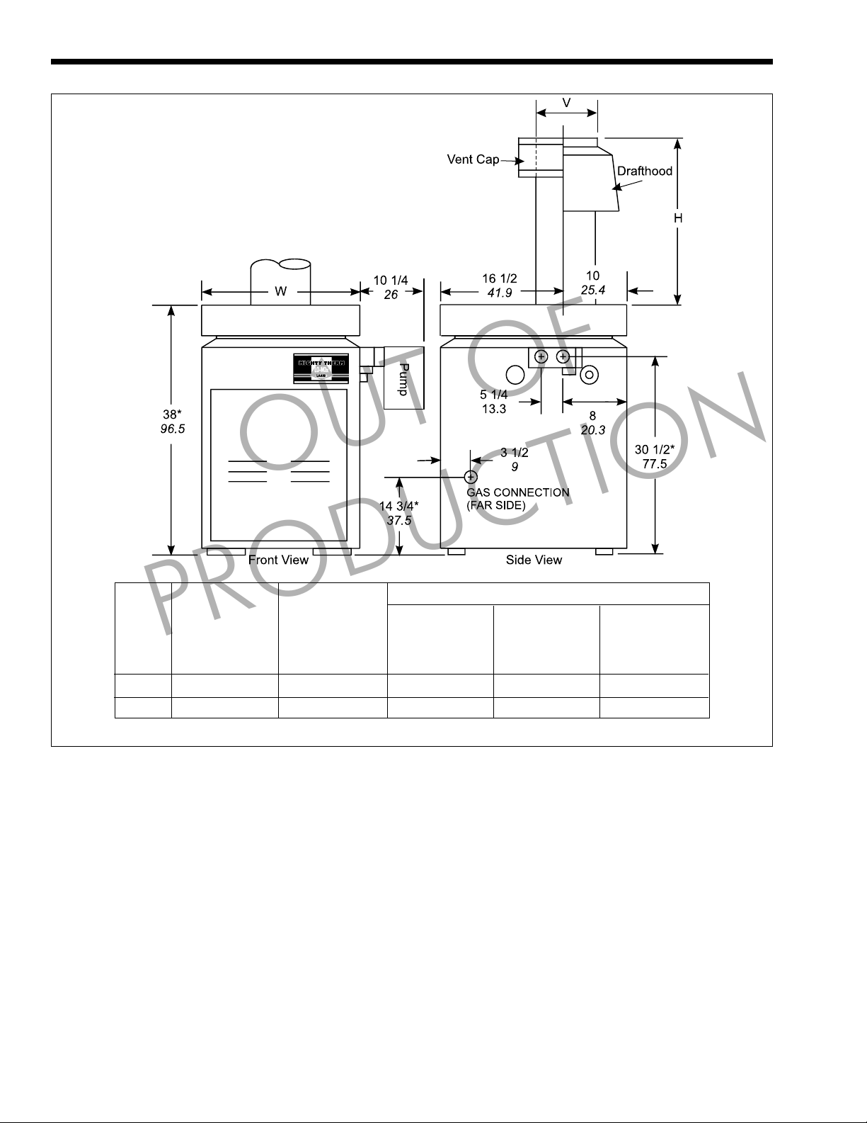
NOTE:* For outdoor models, add 6 inches (15.2cm) for
outdoor base.
Dimensions shown in inches
(centimeters)
OUT OF
Venting Dimensions
Model Firing Heater
Size Rate Width
PRODUCTION
MBtu/h kW in cm in cm in cm in cm
250 250 73.3 22 1/2 57.2 7 17.8 18 1/4 46.4 25 1/4 64.1
400 399 117.0 31 3/4 80.6 9 22.9 21 1/2 54.6 27 1/2 69.9
All dimensions are nominal.
“W” “V” “H” “H”
Drafthood Vent Outdoor Indoor
Vent Cap Diameter Dim Dim
Figure 1. General Configuration.
Page 5

Mighty Therm LO-NOx Hydronic Boiler
Page 5
SECTION 2.
Installation Instructions
2.1 General Information
WARNING
Improper installation or maintenance can cause
nausea or asphyxiation from carbon monoxide in
flue gases which could result in severe injury,
property damage or death. Follow the
manufacturer’s maintenance schedule for the
appliance. Follow local regulations with respect to
installation of carbon monoxide (CO) detectors.
MISE EN GARDE
Une mauvaise installation ou un entretien inadéquat
peut être la cause de nausées ou d’asphyxie en
raison de la présence de niveaux dangereux de
monoxyde de carbone dans les résidus de
combustion et peut entraîner des dommages
matériels, des blessures ou même la mort. Suivre
les directives du fabricant au sujet du programme
d’entretien de l’appareil. Suivre les règlements
locaux touchant l’installation de détecteurs de
monoxyde de carbone (CO).
All gas-fired products require correct installation
to assure safe operation. The requirements for boilers
include the following:
1. Field assembly of drafthood or vent cap (see
2. Appropriate site location clearances and flooring.
3. Suf ficient combustion and ventilation air.
4. Adequate venting of combustion products.
5. Adequate water flow.
6. Properly sized gas meter and piping.
7. Proper electrical wiring.
meet these requirements. Review all application and
installation procedures completely before continuing
the installation.
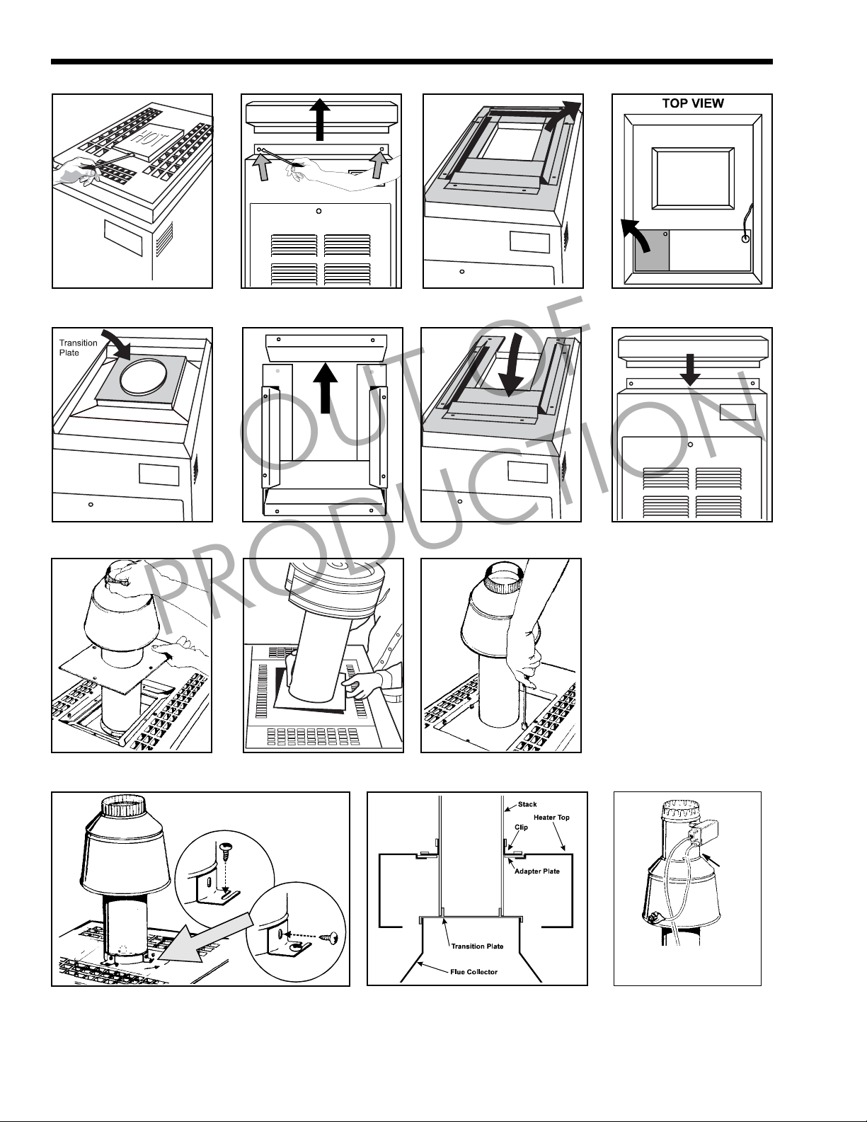
2.2 Field Assembly
with the top assembly in the low-profile configuration
for outdoor installations.
indoor installation when equipped with a special
drafthood, which must be installed without
modification. The part number for the drafthood is on
the boiler rating plate. Follow this procedure to make
the conversion:
PRODUCTION
Section 2.2).
This manual provides the information needed to
The HH, PH boilers are shipped from the factory
The HH, PH boilers are design certified for
OUT OF
1. Remove the top plate, stamped "HOT", by
slipping a fine-blade screwdriver into the slot and
prying it up (see Figure 2).
2. Remove the top by removing all eight screws
connecting it to the jacket (see Figure 3).
3. Remove the rainguard assembly (see Figure 4).
4. Remove the two screws securing the left
vestibule cover (see Figure 5). The cover can be
discarded.
5. Remove the vent cap or drafthood and
accessories from the carton.
NOTE: Vent cap is for outdoor installation, when
required.
6. Place transition plate (with 14" long side)
securely on top of flue collector so flue gases will
not leak (see Figure 6).
7. Remove back portion of rainguard (see Figure 7).
8. Re-install the rainguard (see Figure 8).
9. Replace boiler top and all eight screws (see
Figure 9).
10. Slide the adapter plate up over the bottom of the
stack extension. Fit the stack extension, of the
drafthood or the vent cap, on top of the collar of
the flue transition plate (see Figures 10 and 11).
11. Seat the adapter plate on the top assembly , and
secure it with screws supplied in the kit (see
Figure 12).
12. Attach the clips to the adapter plate by securing
the slotted side of the clips with the screws in the
kit (see Figure 13).
13. Use the holes in the clips as guides to drill three
1/8" dia. holes in the stack.
14. Secure the stack to the clips with the screws
supplied in the kit (see Figure 13).
15. Figure 14 shows a cross-section of the finished
installation.
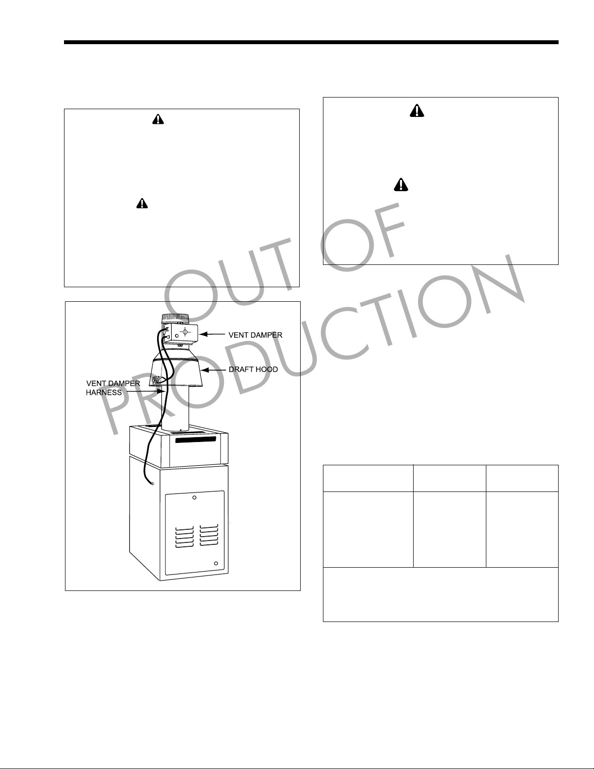
16. Find the vent damper box which is located in the
boiler package (boiler model 250 only).
17. Install the vent damper directly to the top of the
draft hood outlet. The damper operator should
face to the front of the boiler, and the flow
direction arrow should point upward. Use the
vent damper wire harness to connect the vent
damper to the boiler. The bracket end of the
harness should be connected to the vent damper
actuator (see Figure 16).
18. Plug the wiring for the drafthood switch into the
receptacle on the left side of the vent damper box
(see Figure 15).
19. Do not modify the automatic vent damper device.
The venting system must be arranged so that only
the boiler is served by the vent damper device
supplied with the boiler. Provide at least six
Page 6
Page 6
LAARS Heating Systems
Figure 2. Figure 3.
Figure 4. Figure 5.
OUT OF
Figure 6. Figure 7. Figure 8. Figure 9.
PRODUCTION
Figure 10. Figure 11.
Figure 13. Figure 14.
Figure 12.
Figure 15. Drafthood
Switch Receptacle.
Page 7
Mighty Therm LO-NOx Hydronic Boiler
Page 7
inches clearance between the automatic vent
damper and combustible construction, and be
sure to allow access for servicing the damper.
WARNING
Do not force the damper to open or close by moving
the damper blade, turning the shaft, or turning the
position indicator. Doing so can cause an unsafe
condition, leading to property damage, injury or
death.
MISE EN GARDE
Ne pas forcer l’ouverture ou la fermeture du registre
en faisant bouger le volet du registre, en tournant la
tige ou en tournant l’indicateur de pression. Cela
peut engendrer une situation non sécuritaire
susceptible de provoquer des dégâts matériels, des
blessures ou la mort.
OUT OF
PRODUCTION
2.3 Site Location
2.3.1 Installation Information
WARNING
Improper installation or maintenance can cause
nausea or asphyxiation from carbon monoxide in
flue gases which could result in property damage,
severe injury, or death.
MISE EN GARDE
Une mauvaise installation ou un entretien inadéquat
peut provoquer la nausée ou l’asphyxie en raison
de la présence de niveaux dangereux de monoxyde
de carbone dans les résidus de combustion et peut
entraîner des dommages matériels, des blessures
ou même la mort.
Avoid placing the boiler in locations where it can
cause damage by water or condensate leakage. If this is
not possible, provide a suitable drain pan under the
boiler to catch and divert any leakage. The pan must
not restrict air flow around the boiler.
Locate the boiler to provide adequate clearance
on all sides for inspection, service and to provide
adequate air circulation for proper operation.
Locate the boiler so the clearances from
combustible surfaces shown in Table 1 and Figure 17
are met.
Locate the boiler on a waterproof floor with a
floor drain and a 6 inch (15.2 cm) minimum curb on all
four sides to protect the building if boiler repairs are
needed.
Figure 16. Vent Damper Installation (Model 250 only).
Indoors Outdoors
Clearance from: inch cm inch cm
Top 37 94 Unobstructed
Water conn. side 12 30.5 Unobstructed
Opposite side 6 15.2 6 15.2
Front Alcove Unobstructed
Rear 6 15.2 6 15.2
Vent* 6 15.2 —
Flooring: Combustible
Service clearance = 36 inches (91.4cm) at front of boiler,
and 18 inches (46cm) at water connection side.
*1" (2.5cm) if double wall vent is used.
6" base for outdoor boiler is required.
Table 1. Minimum Boiler Clearances
from Combustible Surfaces.
Page 8
Page 8
2.3.2 Outdoor Installation
Caution
Outdoor installations are not recommended in areas
where the danger of snow blockage exists.
Avertissement
L’installation à l’extérieur n’est pas recommandée
dans les zones où il y a des risques d’obstruction
par la neige.
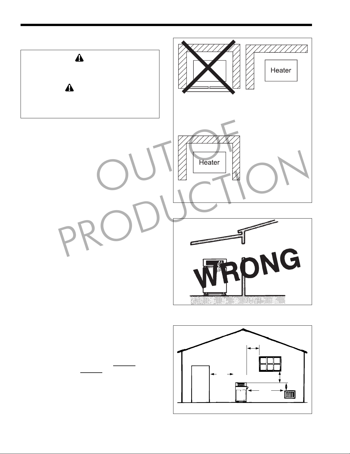
1. Locate the boiler in an open, unroofed area. Do
not locate the boiler below or adjacent to any
doors, windows, louvers, grills, etc., which
connect in any way with an inhabited area of a
building, even though the access might be
through another structure such as a garage or
utility room (see Figure 18 and Table 1).
2. There must be a minimum of 4 feet (1.22 m)
horizontally and vertically between the boiler and
any door, window, or gravity inlet to a building
OUT OF
(see Figure 19).
3. Minimum clearance of 4 feet (1.22m) [6 feet
(1.83m) in Canada] horizontally from, and in no
case above or below , unless the minimum
horizontal distance is maintained, from electric
meters, gas meters, regulators and relief
equipment.
4. If the boiler is installed close to a structure,
protect it from rain water runoff with rain gutters
PRODUCTION
on the roof or other measures. Do not locate the
boiler near sprinkler systems that could spray
water on it.
5. Avoid locations where wind deflection off nearby
structures might cause wind loading and
downdraft conditions. Where downdraft
conditions exist, locate the boiler at least 3 feet
(0.91 m) from the structure.
LAARS Heating Systems
Closet Installation
(unacceptable)
A closet is any 4 sided enclosure
which is less than 16* times the
total volume of all the gas fired
appliances within the enclosure.
REAR
FRONT
* When the ceiling height exceeds 8 feet, you are only allowed to
consider 8 feet when calculating the total volume of the enclosure.
Figure 17. Alcove Installation.
WINDOW
OR GRILL
Figure 18. Incorrect Outdoor Installation.
Room Installation
(acceptable)
A room is any enclosure which is
at least 16* times greater than the
total volume of all the gas fired
appliances within the enclosure
Alcove Installation
(acceptable)
An alcove suitable for the
installation of a heater is a
restricted section of a room not
separated from the room by a door
or partition and which meets the
minimum clearances specified in
this manual.
INDOOR
ROOM
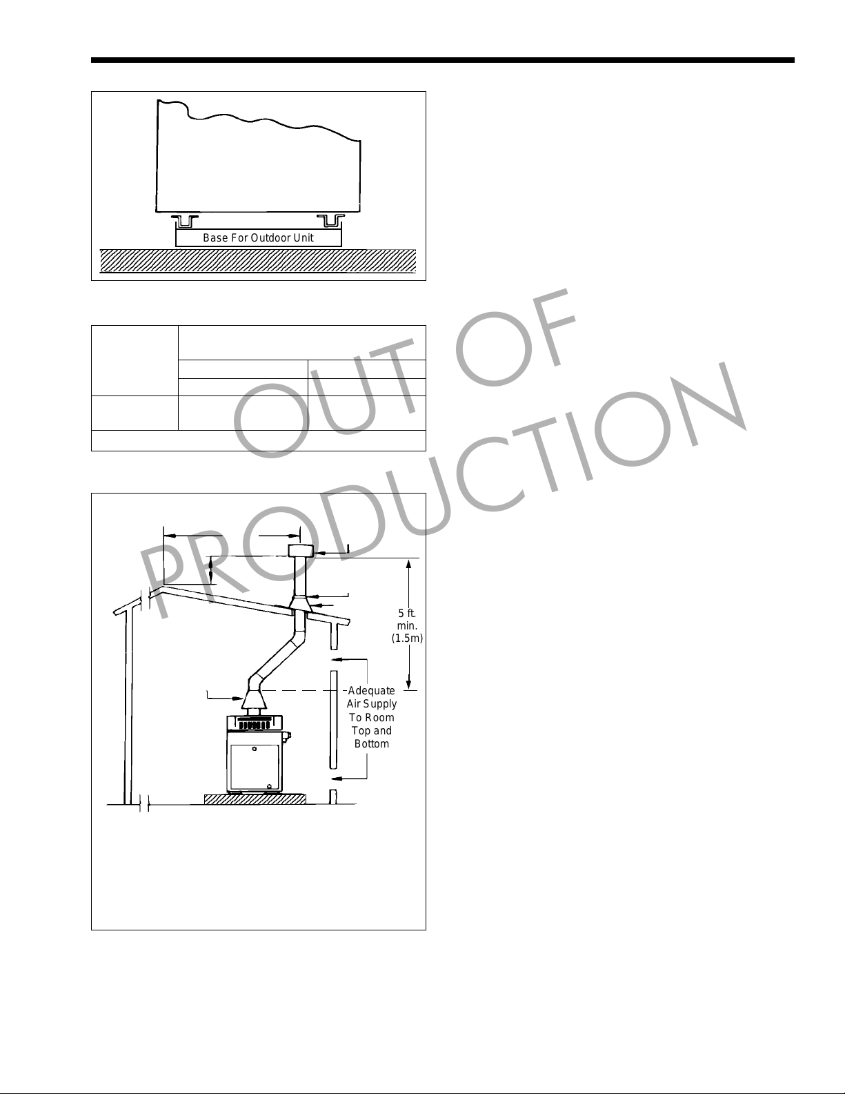
2.3.3 Flooring - T ypical Installation
All outdoor boilers must be installed with the
special base, as a standard part of the boiler. The base,
part number R0368900, is provided in a separate
package. The boiler is designed and certified for
installation on combustible flooring.
the boiler on carpeting.
NEVER store objects on or
NEVER install
around the base of the boiler. For outdoor base
installation, see Figure 20.
2.4 Combustion and Ventilation
Air Supply
All indoor installations must have openings to
outside air for combustion, ventilation and dilution of
flue gases from inside the building (see Figure 21 and
4 ft.
(1.2m)
4 ft.
(1.2m)
10 ft.
(3.0m)
Minimum Clearances
Figure 19. Outdoor Location Installation.
4 ft.
(1.2m)
3 ft.
(0.9m)
Forced Air Inlet
Page 9
Mighty Therm LO-NOx Hydronic Boiler
5
5
5
12345678901234567890123
1
3
12345678901234567890123
LAARS
UNIT
(Side View)
2345678901234567890123456789012123456789012345678901234567890121234
2345678901234567890123456789012123456789012345678901234567890121234
2345678901234567890123456789012123456789012345678901234567890121234
Figure 20. Base for Outdoor Installation.
Base For Outdoor Unit
Page 9
T able 2 ). Laars does not recommend indoor
installations that do not provide combustion air from
outside the building.
Boiler rooms which are confined spaces require
two permanent air supply openings: one within 12
inches (30.5 cm) of the ceiling, the other within 12
inches (30.5 cm) of the floor.
NOTE: Check with louver manufacturers for net free
area of louvers. If screens or louvers are installed, add
50 percent for each screen/louver to the net free area.
Check the latest edition of ANSI Z223.1 or in Canada
CSA B149 and all local codes applicable to
combustion air.
Required Net Free Opening Area
Directly from Outside
At Top At Bottom
Model in.
250 63 406 63 406
400 100 645 100 645
Note: For screens or louvers, add 50%.
Table 2. Air Openings to Outside.
Vent terminated at
least 2 ft. (61cm)
above any
object within
10 ft. (3.0m)
PRODUCTION
1/4 in. (0.6cm)
Minimum Pitch
Per Foot of
Horizontal Pipe
Notes:
1. The drafthood must sit directly on top of the heater
as shown and must not be altered in any manner.
2. An Underwriters' Laboratories listed vent cap is required to eliminate downdraft and allow the heater
to function properly.
3. Use approved roof fitting.
Figure 21. Indoor Installation and Venting.
2
10 ft.
(3.0m)
2 ft. (61cm)
Drafthood
234567890123456789012
cm
2
in.
2
cm
OUT OF
Listed Vent
Cap
Storm Collar
Roof Jack
Adequate
Air Supply
To Room
Top and
Bottom
2
5 ft.
min.
(1.5m)
2.4.1 Outdoor Air Supply
When combustion air comes directly through an
outside wall, each opening must have a minimum free
area of at least one square inch for each 4,000 BTU/h
input of the total input rating of all appliances in the
enclosed area. (In Canada, refer to CSA B149.1)
2.4.2 Indoor Air Supply
Confined and non-confined areas have different
requirements for installation. Check the latest edition
of ANSI Z223.1 or in Canada CSA B149 and all local
codes applicable to combustion air.
2.4.3 Exhaust Fans or Vents
Any equipment which uses air or removes air
from the boiler room can use up the combustion air
supply or reverse the natural draft action of the venting
system. This could cause flue products to build up in
the boiler room. More air must be supplied to make up
for the decrease.
2.5 V enting (Category I)
2.5.1 General Information
When installed indoors, the drafthood must be
connected to a venting system. The venting system
must be installed by a qualified installer and in
accordance with the latest edition of ANSI Z223.1. In
Canada, the installation must be in accordance with
CSA B149.1, and any local codes that apply.
The vent pipe must have a listed vent cap, and
extend at least 2 feet (0.6 m) above any object within a
10 foot (3.0 m) radius.
NOTE: Do not use sheet metal screws at the snap
lock joints of Type B double-wall gas vents.
Do not weld or bolt the vent pipe to the boiler
drafthood. The weight of the stack must not rest on the
boiler. The drafthood and boiler top must be easily
removable for normal boiler service and inspection.
Page 10
Page 10
LAARS Heating Systems
WARNING
Avoid ending boiler vents near air conditioning or air
supply fans. The fans can pick up exhaust flue
products from the boiler and return them inside the
building, creating a possible health hazard, resulting
in serious injury or death.
MISE EN GARDE
Éviter de placer les sorties d’évent près des
appareils de climatisation ou les ventilateurs des
prises d’air. Ces prises d’air peuvent aspirer les
résidus de combustion et les faire pénétrer à
l’intérieur de l’immeuble, ce qui peut représenter
une menace pour la santé et occasionner des
blessures corporelles sérieuses ou même la mort.
Locate unit as close as practical to a chimney or
vent termination. Have horizontal runs sloping
upwards not less than 1/4 inch per foot (21mm/m)
from the boiler to the vent terminal. Support a vent
connector for the design and weight of the material
used to maintain clearances and prevent physical
damage and separate of joints.
Doivent présenter des tronçons horzontaux dont
la pente montante est d’au moins 1/4 po par pied
21mm/m) entre la chaudière et l’évent. Doivent
préciser que les sections horizontales doivent être
supportées pour prévenir le fléchissement.
Always use double-wall or insulated vent pipe
(Type B or equivalent).
In cold weather, uninsulated outside vents can chill
the rising flue products, blocking the natural draft
action of the venting system. This can create a
serious health hazard which can ultimately cause
death by spilling flue products into the boiler room.
Dans les régions froides, les évents non isolés
peuvent occasionner la condensation des résidus
de combustion qui y circulent, ce qui a pour effet de
réduire le tirage naturel du système d’évacuation
des résidus. Cela peut représenter une sérieuse
menace pour la santé, pouvant même provoquer la
mort en causant le refoulement des résidus de
combustion dans la chaufferie.
Avoid oversize vent piping or extremely long
runs of the pipe which may cause too much cooling
and condensation of flue gases.
When the installation of a power vent or draft fan
in the venting system is necessary , qualified personnel
should design the installation following good
PRODUCTION
WARNING
MISE EN GARDE
OUT OF
engineering practices and all applicable codes. A
suitable draft switch must be wired into the boiler
control circuit at the terminal designated Field
Interlock to keep the boiler from firing unless there is a
positive draft.
2.5.2 Common Venting Systems
Venting Multiple Appliances
When installing venting for a Mighty Therm LoNOx boiler or water heater installed as a Category I
fan-assisted appliance with other Category I appliances
through one shared duct called a “common vent”,
special care must be taken by the installer to ensure
safe operation. In the event that the common vent is
blocked, it is possible, especially for fan-assisted
devices, to vent backwards through non-operating
appliances sharing the vent, allowing combustion
products to infiltrate occupied spaces. If the
appliances are allowed to operate in this condition,
serious injury or death may occur.
WARNING
Operation of appliances with a blocked common
vent may lead to serious injury or death. Safety
devices must be implemented to prevent blocked
common vent operation. If safe operation of all
appliances connected to a common vent cannot be
assured, including prevention of spillage of flue
gasses into living spaces, common venting should
not be applied, and appliances should each be
vented separately.
AVERTISSEMENT
Le fonctionnement des appareils avec un système
d’évacuation bloqué peut provoquer des blessures
graves, voire la mort. Des dispositifs de sécurité
doivent être installés pour éviter le blocage des
systèmes d’évacuation. Si le fonctionnement de
tous les appareils connectés à un système
d’évacuation commun ne peut pas être assuré, y
compris la prévention de la dispersion des gaz
toxiques dans les espaces habités, on ne devrait
pas installer un système d’évacuation commun et
chaque appareil devrait être ventilé séparément.
It is for this reason that, in addition to following
proper vent sizing, construction and safety
requirements from the National Fuel Gas Code, ANSI
Z223.1 or in Canada, from CSA B149.1 as well as all
applicable local codes, it is required that installers
provide some means to prevent operation with a
blocked common vent. It is suggested that a blocked
vent safety system be employed such that if the switch
from one appliance trips due to excessive stack spill or
backpressure indicating a blocked vent condition, that
all appliances attached to the vent be locked out and
prevented from operating. As an additional precaution,
it is recommended that a Carbon Monoxide (CO)
Page 11

Mighty Therm LO-NOx Hydronic Boiler
Page 11
alarm be installed in all enclosed spaces containing
combustion appliances. If assistance is required in
determining how a blocked vent safety system should
be connected to a LAARS product, please call
Applications Engineering at (603) 335-6300.
Refer to the installation and operating
instructions on all appliances to be common vented for
instructions, warnings, restrictions and safety
requirements. If safe operation of all appliances
connected to a common vent cannot be assured,
including prevention of spillage of flue gasses into
living spaces, common venting should not be applied,
and appliances should each be vented separately .
2.5.3 Inspection of Commonly Vented
Appliances
If the instrumentation of this boiler replaces an
older boiler in a common vent system with other
appliances, or if you remove additional appliances
from the common vent, all the appliances must be
checked for proper venting.
At the time of removal of an existing boiler, the
following steps shall be followed with each appliance
remaining connected to the common venting system
placed in operation, while the other appliances
remaining connected to the common venting system
are not in operation.
1. Seal any unused openings in the common venting
system.
Sceller toutes les ouvertures non utilisées du
système d’évacuation.
2. Visually inspect the venting system for proper
3. Insofar as it is practical, close all building doors
PRODUCTION
size and horizontal pitch and determine there is
no blockage or restriction, leakage, corrosion and
other deficiencies which could cause an unsafe
condition.
Inspecter de façon visuelle le système
d’évacuation pour déterminer la grosseur et
l’inclinaison horizontale qui conviennent et
s’assurer que le système est exampt
d’obstruction, d’étranglement, de fuite, de
corrosion et autres défaillances qui pourraient
présenter des risques.
and windows and all doors between the space in
which the appliances remaining connected to the
common venting system are located and other
spaces of the building. Turn on clothes dryers and
any appliance not connected to the common
venting system. Turn on any exhaust fans, such
as range hoods and bathroom exhausts, so they
will operate at maximum speed. Do not operate a
summer exhaust fan. Close fireplace dampers.
Dans la mesure du possible, fermer toutes les
portes et les fenêtres du bâtiment et toutes les
portes entre l’espace où les appareils toujours
OUT OF
raccordés au système d’évacuation sont installés
et les autres espaces du bùtiment. Mettre en
marche les sécheuses, tous les appareils non
raccordés au systéme d’évacuation commun et
tous les ventilateurs d’extraction comme les
hottes de cuisinière et les ventilateurs des salles
de bain. S’assurer que ces ventilateurs
fonctionnent à la vitesse maximale. Ne pas faire
fonctionner les ventilateurs d’été. Fermer les
registres des cheminées.
4. Place in operation the appliance being inspected.
Follow the lighting instructions. Adjust
thermostat so appliance will operate
continuously.
Mettre l’appareil inspecté en marche. Suivre les
instructions d’allumage. Régler le thermostat de
façon que l’appareil fonctionne de façon
continue.
5. Test for spillage at the draft hood relief opening
after 5 minutes of main burner operation. Use the
flame of a match or candle, or smoke from a
cigarette, cigar or pipe.
Faire fonctionner le brûleur principal pendant 5
min ensuite, déterminer si le coupe-tirage
déborde à l’ouverture de décharge. Utiliser la
flamme d’une allumette ou d’une chandelle ou la
fumée d’une cigarette, d’une cigare ou d’une
pipe.
6. After it has been determined that each appliance
remaining connected to the common venting
system properly vents when tested as outlined
above, return doors, windows, exhaust fans,
fireplace dampers and any other gas burning
appliance to their previous conditions of use.
Une fois qu’il a été déterminé, selon la méthode
inidquée ci-dessus, que chaque appareil raccordé
au système d’évacuation est mis à l’air libre de
façon adéquate. Remettre les portes et les
fenêtres, les ventilateurs, les registres de
cheminées et les appareils au gaz à leur position
originale.
7. Any improper operation of the common venting
system should be corrected so the installation
conforms with the National Fuel Gas Code, ANSI
Z223.1. When resizing any portion of the
common venting system, the common venting
system should be resized to approach the
minimum size as determined using the
appropriate tables in Appendix G in the National
Fuel Gas Code, ANSI Z223.1.
T out mauvais fonctionnement du système
d’évacuation commun devrait être corrigé de
façon que l’installation soit conforme au national
Fuel Gas Code, ANSI Z223.1 et (ou) aux codes
d}installation CSA-B149.1. Si la grosseur d’une
Page 12

Page 12
LAARS Heating Systems
section du système d’évacuation doit être
modifiée, le système devrait être modifié pour
respecter les valeurs minimales des tableaux
pertinents de l’appendices F du National Fuel
Gas Code, ANSI Z2231.1 et (ou) des codes
d}installation CSA-B149.1.
2.6 Water Flow System
2.6.1 Freeze Protection
Proper precautions for freeze protection are
recommended for boiler installations in areas where
the danger of freezing exists.
Power outage, interruption of gas supply , failure
of system components, activation of safety devices,
etc., may prevent a boiler from firing. Any time a
boiler is subjected to freezing conditions, and the
boiler is not able to fire, and/or the water is not able
to circulate, there is a risk of freezing in the boiler
or in the pipes in the system. When water freezes, it
expands. This can result in bursting of pipes in the
system, or damage to the boiler, which could result in
leaking or flooding conditions.
Do not use automotive anti-freeze. Maintaining a
mixture of minimum 50% water and maximum 50%
properly inhibited HVAC glycol, which contains an
antifoamant, is the preferred method of freeze
protection for Mighty Therm boilers. Percentage of
glycol used in the Mighty Therm boiler must not
exceed 50%. Typically, this mixture will serve as burst
protection for temperatures down to approximately
-35°F (-30°C). To get the desired temperature rise
OUT OF
PRODUCTION
across the boiler when the is mixture is used, increase
the water flow by 15% above the original
recommendation. Increase the head loss requirement
by 20%.
IMPORTANT NOTES: Different glycol products may
provide varying degrees of protection. Glycol products
must be maintained properly in a heating system, or
they may become ineffective. Consult the glycol
specifications, or the glycol manufacturer, for
information about specific products, maintenance of
solutions, and set up according to your particular
conditions.
2.6.2 Pump Requirements
High recovery , low volume water boilers need
enough water flow for efficient operation. The system
pump must develop enough pressure to overcome the
pressure drop of the boiler plus the pressure drop of
the entire circulation system at the flow rates selected
from T able 3.
The correct flow rate can be verified by checking
the temperature rise of water as it passes through the
boiler. T o check the temperature rise, measure the
difference in water temperature between the boiler
inlet and outlet to determine flow . For example: If a
Size 250 boiler is installed; the inlet water temperature
is 160°F (71°C); and the outlet water temperature is
185°F (85°C); then there is a 25°F (14°C) temperature
rise. Per Table 3 this equals a flow rate of 16 GPM
(1.0L/s) and a head loss (pressure drop) of 1.2 feet of
water. If a higher temperature rise is measured, flow
Figure 22. Multiple Boilers, Primary Secondary Sytem.
Page 13

Mighty Therm LO-NOx Hydronic Boiler
Page 13
OUT OF
Figure 23. Multiple Boilers, Low Temperature System.
Temperature Rise in °F °C
PRODUCTION
Size GPM H/L* L/s GPM H/L* L/s GPM H/L* L/s GPM H/L* L/s
250 20 2.1 1.26 0.6 16 1.00 1.2 0.4 13 0.82 0.8 0.2 11 0.69 0.6 0.2
400 31 1.96 5.2 1.6 25 1.58 3.4 1.0 21 1.32 2.3 0.7 18 1.13 1.7 0.5
Water Flow - GPM or L/s: Gallons per minute or Liters per second.
*Pressure drop (head loss) through the boiler, expressed in feet or meters of water (H
must be increased by changing the piping or pump
size.
2.6.3 Variable Water Flow Systems
There can be reduced water flow through the
boiler in heating systems using zone valves, zone
pumps or 3-way valves. This can result in a high
temperature rise across the boiler. Laars recommends
primary-secondary pumping for all variable flow
systems. The boiler pump in a primary-secondary
system maintains constant flow through the boiler even
though the system flow is variable. In a primarysecondary system the pressure drop of the boiler is not
added to the system (see Figures 22, 23 and 24).
20°F 11°C 25°F 14°C 30°F 17°C 35°F 19°C
ft m ft m ft m ft m
0).
2
Table 3. Temperature Rise.
2.6.4 System Pressure Requirements
The HH, PH boilers are designed to operate on
closed, pressurized systems. A minimum of 12 psi
(82.7kPa) should be maintained on the system where
boiler supply water temperatures are 200°F (93°C) or
less. If higher temperatures are required, the minimum
system pressure should be at least 15 psi (103.4 kPa)
above the water vapor pressure corresponding to the
elevated water temperature.
Do not use the HH, PH boilers to operate on
open, pressurized systems unless the supply water
temperatures are kept below 180°F (82°C), and a
minimum of 5 psi (34.5 kPa) static head is maintained
at the boiler.
Page 14

Page 14
LAARS Heating Systems
OUT OF
Figure 24. One Boiler, Multi-Temperature System.
2.6.5 Chilled Water Systems
If the boiler is part of a refrigeration system,
include the proper valves to isolate the boiler from the
refrigeration system during times when the boiler is
not operating.
When the boiler piping is connected to heating
coils, which are close to refrigerated air circulation,
install flow control valves or other automatic methods
to prevent gravity circulation of the boiler water during
the cooling cycle.
2.6.6 System to Boiler Piping
1. Install gate valves at the inlet and outlet to the
boiler so it can be isolated for service.
2. Make sure the pressure relief valve (see Figure
25) has its outlet piped to a drain or floor sink.
Pay special attention to relief valve settings in
installations where the boiler is located on the
ground floor of a tall building, or where the
operating temperature of the boiler is above
210°F (99°C). In both cases, the static pressure of
the system is raised. This would bring raw water
into the system. The factory will furnish a 75 psi
(516.8 kPa) setting unless a special setting is
ordered.
PRODUCTION
Pressure
Flow
Switch
Figure 25. Pressure Relief Valve.
3. Install a low water cutoff device if the boiler is
installed above radiation level.
4. Install manual and/or automatic air venting
devices at high points in the system to get rid
of air.
5. Install a correctly sized expansion or
compression tank in accordance with the
manufacturer's instructions.
Relief Valve
High-Limit
Dry Well
Page 15

Mighty Therm LO-NOx Hydronic Boiler
Page 15
6. Support the weight of all water and gas piping
with suitable hangers or floor stands.
7. Check piping diagrams with local applicable
plumbing, heating and building safety codes.
2.6.7 Filling the System
1. Close all air vents and open the makeup water
valve. Let the system fill slowly .
2. If a makeup water pump is used, adjust the
pressure switch on the pumping system to
maintain at least 12 psi (82.7 kPa) at the highest
point in the heating loop.
3. If a water pressure regulator is installed on the
makeup water line, adjust the pressure regulator
to provide at least 12 psi (82.7 kPa) at the highest
point in the heating loop.
4. Open air vents on all radiation units at the high
points in the piping throughout the system, unless
automatic air vents are installed at those points.
5. Run the system circulating pump for at least 30
minutes with the boiler shut off.
6. Recheck all air vents as described in S tep 4 above.
7. With the system full of water and under normal
operating pressure, the air pressure in the expansion
tank should be at least 12 psi (82.7 kPa).
8. Start up the boiler following the instructions
found on the inside of the boiler.
9. Operate the whole system, including the pump,
boiler, and radiation units for 1 hour.
PRODUCTION
10. Shut down the entire system and vent all
radiation units and high points in the system
piping as described in Step 4 above.
11. Close the makeup water valve and check the
strainer in the pressure reducing valve for sediment or debris. Reopen the makeup water valve.
12. Check the gauge to make sure the water pressure
is right, and check water level in the system. If
the water level indicated above the boiler shows
that water is at the highest point in the circulating
loop, then the system is ready for operation.
13. Within 3 days of start-up, recheck all air vents
and expansion tank as described in Steps 4 and 8
above.
2.6.8 Minimum Boiler T emperature
The boiler inlet water temperature must be
minimum 110°F (43°C) when the system has come up
to normal operating conditions. Lower temperature
inlet water may allow the production of condensation
on the outside of the copper finned tubes, which can
block the flue gases and/or cause improper
combustion, leading to heat exchanger sooting.
OUT OF
For systems with lower than 110°F (43°C)
temperature, boiler must be protected from low
temperature return water. There are many methods of
achieving low temperature protection. Figure 23
shows an example of such a system. Damage caused
by condensation is not covered under the terms of the
limited warranty .
2.7 Gas Supply and Piping
(Natural Gas Only)
2.7.1 General Instructions
Review the following instructions before
continuing the installation.
1. Gas piping installation must be in accordance
with the latest edition of ANSI Z223.1. In
Canada, the installation must be in accordance
with CSA-B149.1 and all loc a l c od e s t ha t a p pl y.
2. Check the rating plate to make sure the boiler is
fitted for the type of gas being used. Laars LO-
NOx boilers are normally equipped to operate
with natural gas below a 2000 foot (609 m)
altitude.
3. If a gas pressure regulator is required, the
installation must be in accordance with the latest
edition of ANSI Z223.1. In Canada, the
installation must be in accordance with CSA-
B149.1 and all local codes that apply .
4. The figures in Table 5 should be used to size the
gas piping from the gas meter to the boiler.
5. Install a sediment trap (drip leg) ahead of the gas
controls (see Figure 26). Fit the trap with a
threaded cap which can be removed for cleaning.
6. Install a non-restrictive manual gas shutoff valve
for service and safety . Check the local codes.
7. Disconnect the boiler and its individual shutoff
valve from the supply gas system during pressure
Distance from Gas Meter or Last Stage Regulator
0-100 feet 100-200 feet 200-300 feet
0-30 m 30-60 m 60-90 m
Boiler Nat. Nat. Nat.
Size in. (NPT) in. (NPT) in. (NPT)
250 1¼ 1¼ 1½
400 1¼ 1½ 2
Notes:
1. These numbers are for natural gas (0.65 Sp. Gr.) and
are based on ½ inch (13mm) water column pressure
drop. Check supply pressure with a manometer, and
local code requirements for variations.
2. Check supply pressure and local code requirements
before preceding with work.
3. Pipe fittings must be considered when determining gas
pipe sizing.
Table 5. Pipe Size Requirements (natural gas).
Page 16

Page 16
G
S
I
O
R
T
LAARS Heating Systems
MANUAL SHUT-OFF
VALVE
CAP
NIPPLE
UNION
T
BOILE
INLE
AS
UPPLY
NLET
Figure 26. T-Fitting and Sediment Trap.
T-FITTING
3" (76 mm)
MIN.
testing of the system at pressures higher than 1/2
pounds per square inch (psi) (3.4 kilopacals
[kPa]). If the test pressure is equal to or less than
1/2 psi (3.45 kPa), close the manual shutoff valve
on the boiler during the piping pressure test.
8. Gas supply pressures to the boiler are listed in
T able 6.
OUT OF
Supply Pressure Natural Gas
Water Column in. mm
Minimum 6 152
See Rating Plate
Maximum 10.5 267
Table 6. Gas Supply Pressure Requirements.
PRODUCTION
NOTE: The boiler and all other gas appliances sharing
the boiler gas supply line must be firing at maximum
capacity to properly measure the inlet supply
pressure. Low gas pressure could indicate an undersized gas meter and/or obstructed gas supply line.
9. Do not exceed the maximum inlet gas pressures
specified. Excessive pressure will result in
damage to the boiler's gas controls. The minimum
pressure specified is for gas input adjustment.
10. The correct burner manifold gas pressure is
stamped on the rating plate. The regulator on the
gas valve is preset at the factory, and does not
normally need adjustment.
11. Before operating the boiler, test the complete gas
Since some leak test solutions (including soap and
water) may cause corrosion or stress cracking,
rinse the piping with water after testing.
Étant donné que certaines solutions utilisées pour
vérifier les fuites (dont le savon et l’eau) peuvent
causer la corrosion ou la fissuration, rincer les
canalisations avec de l’eau après avoir effectué les
essais.
2.8 Electrical Wiring
Electrically ground the boiler in accordance with the
latest edition of the National Electrical Code, ANSI/
NFPA 70. In Canada, use C22.1. Do not rely on the
gas or water piping to ground the metal parts of the
boiler. Often, plastic pipe or dielectric unions isolate
the boiler electrically. Service and maintenance
personnel who work on or around the boiler may be
standing on wet floors and could be electrocuted by
an ungrounded boiler. Electrocution can cause
serious injury or death. The electric circuit to which
the unit will be connected should be “OFF” during
installation and wiring of the unit.
La chaudière doit être reliée à la terre en respectant
les exigences de la plus récente édition du National
Electrical Code ANSI/NFPA 70.Au Canada, utiliser
le C22.1. Ne pas avoir recours aux canalisations de
gaz ou d’eau pour relier à la terre les pièces
métalliques de la chaudière. Les tuyaux de
plastique ou raccordements diélectriques servent
souvent à isoler la chaudière au point de vue
électrique. Les employés qui sont appelés à
travailler sur la chaudière ou autour pour effectuer
l’entretien et les réparations peuvent se retrouver
sur un plancher mouillé et risquer l’électrocution si
l’appareil n’est pas adéquatement mis à la terre.
L’électrocution peut occasionner des blessures
graves ou la mort. Le circuit électrique auquel
l’appareil est branché doit être en position d’arrêt
« OFF » durant l’installation et le câblage de
l’appareil.
Caution
Avertissement
WARNING
MISE EN GARDE
supply system and all connections for leaks using
a soap solution.
1. Check boiler wiring and pump for correct
voltage, frequency , and phase. Check to make
sure boiler is wired for 120 volts alternating
current (VAC). If 240 VAC, contact local factory
representative or Laars.
2. Wire the boiler and pump exactly as shown in the
wiring diagram supplied with the boiler. See
Figures 30 through 33 for a typical example of a
wiring diagram.
Page 17

Mighty Therm LO-NOx Hydronic Boiler
Page 17
3. Electrically interlock the pump and boiler so the
boiler cannot come on unless the pump is
running.
4. Connect all field-installed devices (draft
switches, relays, timers, outdoor temperature
reset devices, etc.) to the boiler wiring at points
labeled Field Interlock.
SECTION 3.
Operating Instructions
NOTE: Safe lighting and other performance criteria
were met with the gas manifold and control assembly
installed on the boiler during tests specified in ANSI
Z21.13.
WARNING
For your safety, when starting the boiler, keep your
head and face well away from the lower firebox
opening to prevent any risk of personal injury.
Vent pipes, drafthoods, and boiler tops get hot!
These surfaces can cause serious burns. Do not
touch these surfaces while the boiler is in operation.
Pour assurer sa sécurité, la personne qui allume la
chaudière devrait garder la tête le plus éloignée
possible de l’ouverture inférieure de la chambre de
combustion afin de prévenir tout risque de blessure
au moment de l’allumage.
Les tuyaux d’évent, les coupe-tirage et la surface
supérieure des chaudières deviennent très chauds !
Toucher à ces surfaces peut occasionner des
blessures sérieuses. Ne pas toucher à ces surfaces
alors que la chaudière fonctionne.
3.1 Start-Up Procedure
1. Make sure the system pump is running and there
2. Follow the lighting and shutdown procedure in
3.2 Setting the Temperature Controls
PRODUCTION
is water flow .
Figure 28 or 29.
OUT OF
MISE EN GARDE
Temperature Controller
Manual Reset Hi-Limit
Figure 27. Temperature Controls.
T o set the temperature and high-limit controls:
1. Set the temperature controller at the system
design temperature.
2. For boilers with the temperature controller bulb
at the boiler inlet, set the high-limit 40°F to 50°F
above temperature controller setting.
3. For boilers with the temperature controller bulb
at the boiler outlet, set the high-limit 15°F to
25°F above temperature controller setting.
3.3 Hi-Limit Switch Checkout
After running the boiler for a long enough period,
bring the water temperature within the range of the hilimit switch and slowly back off the high limit setting
until the boiler shuts off. The main burners should
reignite (following the normal ignition cycle) when the
hi-limit switch is reset and turned back up to its
original setting. The boiler should now run until it
shuts off automatically on operating control.
Should overheating occur or the gas supply fail to
shut off, turn off the manual gas control valve to the
boiler (refer to troubleshooting section).
Caution
On a boiler equipped with the vent damper device,
the damper must be in the open position when the
main burners are operating.
Avertissement
Le registre des chaudières munies d’un dispositif
de volet motorisé doit être en position ouverte lors
que les brûleurs principaux fonctionnent.
3.4 Shut-Down Procedure
Shut down the boiler following the instructions in
Figures 28 and 29.
Where there is a danger of freezing, shut off the
water supply and remove the drain plugs on both sides
of the boiler jacket. Drain every part of the system
subject to damage from freezing temperatures.
Page 18

Page 18
LAARS Heating Systems
FOR YOUR SAFETY READ BEFORE OPERATING
WARNING: If you do not follow these instructions exactly, a fire or explosion
may result, causing property damage, personal injury or loss of life.
A. This appliance does not have a pilot light. It is
equipped with an ignition device which
automatically lights the heater. Do NOT try to
light the burners by hand.
B. BEFORE OPERATING, smell all around the
appliance area for gas. Be sure to smell next
to the floor because some gas is heavier than
air and will settle on the floor.
WHAT TO DO IF YOU SMELL GAS
• Do not try to light any appliance
• Do not touch any electric switch; do not
use any phone in your building.
• Immediately call your gas supplier from a
neighbor's phone. Follow the gas
supplier's instructions.
OUT OF
OPERATING INSTRUCTIONS
1. STOP! Read the safety information above on
this label.
2. Turn appliance switch to “OFF” and remove
the heater door.
3. Turn off all electric power to the appliance.
4. Set the thermostat to lowest setting.
5. This appliance is equipped with an ignition
device which automatically lights the heater.
Do not try to light the burners by hand.
6. Turn gas control knob clockwise to
“OFF”.
7. Wait five (5) minutes to clear out any gas.
Then smell for gas, including near the floor. If
you smell gas, STOP! Follow “B” in the safety
information above on this label. If you don't
smell gas, go to next step.
8. Turn gas control knob counterclockwise
to “ON”.
PRODUCTION
• If you cannot reach your gas supplier, call
the fire department.
C. Use only your hand to push in or turn the
gas control knob. Never use tools. If the
knob will not push in or turn by hand, don't
try to repair it, call a qualified service
technician. Force or attempted repair may
result in a fire or explosion.
D. Do not use this appliance if any part has
been under water. Immediately call a
qualified service technician to inspect the
appliance and to replace any part of the
control system and any gas control which
has been under water.
9. Set thermostat to desired setting. Replace
heater door.
10. Turn on all electric power to appliance.
11. Turn applicance switch from “OFF” to “ON”.
12. If the appliance will not operate, check that
the pump is on, and all of the safety switches
are reset. Otherwise, follow the instructions
“To Turn Off Gas To Appliance” and call your
service technician or gas supplier.
TO TURN OFF GAS TO APPLIANCE
1. Turn appliance switch to “OFF”.
2. Remove the heater door.
3. Set the thermostat to lowest setting.
Figure 28. Lighting and Shutdown Instructions.
4. Turn off all electric power to the appliance if
service is to be performed.
5. Turn gas control knob clockwise to “OFF”.
6. Replace heater door.
Page 19

Mighty Therm LO-NOx Hydronic Boiler
POUR VOTRE SÉCURITÉ LISEZ AVANT DE METTRE EN MARCHE
AVERTISSEMENT: Quiconque ne respecte pas à la lettre les instructions dans
la présente notice risque de déclencher un incendie ou une explosion entraînant
des dommages, des blessures ou la mort.
Page 19
A. Cet appareil ne comporte pas de veilleuse. Il est
muni d’un dispositif d’allumage qui allume
automatiquement le brûleur. ne tentez pas
d’allumer le brûleur manuellement.
B. AVANT DE FAIRE FOCTIONNER, reniflez tout
autour de l’appareil pour déceler une odeur de
gaz. Reniflez près du plancher, car certains gaz
sont plus lourds que l’air et peuvent s’accumuler
au niveau du sol.
QUE FAIRE SI VOUS SENTEZ UNE ODEUR DE
GAZ:
• Ne pas tenter d’allumer d’appareil
• Ne touchez à aucun interrupteur; ne pas
vous servir des téléphones se trouvant dans
le bâtiment.
OUT OF
INSTRUCTIONS DE MISE EN MARCHE
1. ARRÊTEZ! Lisez les instructions de sécurité sur la
portion supéerieure de cette étiquette.
2. Mettre le bouton de commande à “OFF”. Enlevez la
portière du chauffe-eau.
3. Coupez l’alimentation électrique de l’appareil.
4. Réglez le thermostat à la température la plus
5. Cet appareil est muni d’un dispositif d’allumage qui
6. Tournez le bouton de la commande de gaz dans le
7. Attendre cinq (5) minutes pour laisser échapper
PRODUCTION
basse.
met le chauffe-eau en marche automatiquement. Ne
pas essayer d’allumer les brûleurs à main.
sens des aiguilles d’une montre jusqu’à la
position “OFF”.
tout le gaz. Reniflez tout autour de l’appareil, y
compris près du plancher, pour déceler une odeur
de gaz. Si vous sentez une odeur de gaz,
ARRÊTEZ! Passez à l’étape B des instructions de
sécurité sur la portion supérieure de cette
étiquette. S’il n’y a pas d’odeur de gaz, passez à
l’étape suivante.
• Appelez immédiatement votre fournisseur
de gaz depuis un voisin. Suivez les
instructions du fournisseur.
• Si vous ne pouvez rejoindre le fournisseur,
appelez le service des incendies.
C. Ne poussez ou tournez la manette
d’admission du gaz qu’à la main; ne jamais
utiliser d’outil. si la manette reste coincée, ne
pas tenter de la réparer; appelez un
technicien qualifié. Le fait de forcer la
manette ou de la réparer peut déclencher une
explosion ou un incendie.
D. N’utilisez pas cet appareil s’il a été plongé
dans l’eau, même partiellement. Faites
inspecter l’appareil par un technicien qualifié
et remplacez toute partie du système de
contrôle et toute commande qui ont été
plongés dans l’eau
8. Tournez le bouton de commande de gaz dans le
sense contraire des aiguilles d’une montre
jusqu’à la position “ON”.
9. Replacez le panneau d’accès aux commandes.
10. Mettez l’appareil sous tension.
11. Réglez le thermostat comme désiré et tournez le
bouton de commande de la position “OFF” à la
position “ON”.
12. Si l’appareil ne se met pas en marche, suivez
les instructions intitulées “Comment couper
l’admission de gaz de l’appareil” et appelez un
technicien qualifié ou le fournisseur de
gaz.
COMMENT COUPER L’ADMISSION DE GAZ DE L’APPAREIL
1. Mettre le bouton de commande à “OFF”. Enlevez la
portiére du chauffe-eau.
2. Réglez le thermostat à la température la plus basse.
3. Couplez l’alimentation électrique de l’appareil s’il
faut procéder à l’entretien.
Figure 29. Instructions D’allumage et de Fermeture.
4. Tournez le bouton de contrôl de gaz dans le sens
des aiguilles d’une montre jusqu’à la position
“OFF”.
5. Replacez le panneau d’accès aux commandes.
Page 20

Page 20
LAARS Heating Systems
OUT OF
PRODUCTION
Figure 30. Mighty Therm LO-NOx, PH250.
Page 21

Mighty Therm LO-NOx Hydronic Boiler
Page 21
OUT OF
PRODUCTION
Figure 31. Mighty Therm LO-NOx, HH250.
Page 22

Page 22
LAARS Heating Systems
OUT OF
PRODUCTION
Figure 32. Mighty Therm LO-NOx, PH 400.
Page 23

Mighty Therm LO-NOx Hydronic Boiler
Page 23
OUT OF
PRODUCTION
Figure 33. Mighty Therm LO-NOx, HH 400.
Page 24

Page 24
SECTION 4.
Maintenance
4.1 General Instructions
1. Oil the water circulating pump in accordance
with the manufacturer's instructions.
2. If a strainer is used in a pressure reducing valve
or in the piping, clean it every 6 months in
accordance with the manufacturer's instructions.
3. At startup and every 6 months after, check the
main burner flame. If the flame has the
appearance of sooting tips, check for debris near
orifices. Call service technician.
LAARS Heating Systems
Plug
Figure 35. Scale Inspection.
(see Figure 35). Perform this inspection after 60
days of and after 120 days of operation. This will
establish a regular inspection routine.
3. Reinstall both plugs after inspection.
OUT OF
Figure 34. Flame Patterns.
4. Inspect the venting system for blockage, leakage,
and corrosion at least once a year.
5. Keep the boiler area clear of combustible
material, gasoline, and other flammable liquids
and vapors.
6. Be sure all combustion air and ventilation
openings are not blocked.
7. Check for black carbon soot buildup on the
external surfaces of the heat exchanger every 6
months.
8. Do not use the boiler if any part has been under
water. Replace anypart of the control system and
any gas control which has been under water.
NOTE: After installation and first startup, check the
heat exchanger for black carbon soot buildup after the
following periods of operation: 24 hours, 7 days, 30
days, 90 days, and once every 6 months thereafter.
PRODUCTION
4.2.2 Cleaning the Heat Exchanger
An inspection and cleaning of the complete heat
exchanger can only be done by removing it from the
boiler.
1. Remove the heat exchanger.
WARNING
Black carbon soot buildup on a dirty heat exchanger
can be ignited by a random spark or flame. To
prevent this happening, dampen the soot deposits
with a wet brush or fine water spray before
servicing the heat exchanger. Ignition of soot can
possibly cause serious injury or burns, and in
extreme cases, death.
MISE EN GARDE
L’accumulation de suie noire ou de saleté sur
l’échangeur thermique peut s’enflammer par le
contact d’une étincelle ou d’une flamme. Humidifier
les dépôts de suie à l’aide d’une brosse mouillée ou
d’une vaporisation d’eau avant d’effectuer
l’entretien de l’échangeur thermique afin
d’empêcher que cela se produise. L’embrasement
de la suie peut occasionner des blessures graves,
de brûlures et même, dans les cas extrêmes, la
mort.
4.2 HEAT EXCHANGER
4.2.1 Inspecting the Heat Exchanger
T o check the scale buildup, periodically inspect
the tube having the highest temperature as follows:
1. Remove the ¼ inch, NPT plug located on the left
side of the boiler.
2. Remove the lar ge, hex-head plug located on the
right side of the boiler under the in/out header
2. Remove the heat baffles and check for a light
accumulation of soot or corrosion on the outside
of the heat exchanger tubes.
NOTE: While the heat exchanger is out of the boiler,
inspect the firewall insulation blankets for wear and
tear. Replace if necessary.
3. Use a wire brush to remove soot and loose scale
from the heat exchanger. Do not use water or
compressed air for cleaning.
Page 25

Mighty Therm LO-NOx Hydronic Boiler
City
Water
Supply
Notes:
1. When pressure relief valve is used, it must be removed and the hole plugged, as shown.
2. Remove the plug before reinstalling the heat exchanger.
Figure 36. Heat Exchanger Tube Cleaning.
400-500 RPM
Drill Motor
Page 25
NOTE: Use only the correct carbide tipped reamers
which are available from Laars.
4. Ream the insides of the tubes (see Figure 36).
5. Pull the reamer out frequently to remove lime
powder and prevent the drill from binding in the
tube.
6. Install new gaskets. Do not reuse the old ones.
7. Tighten the header bolts progressively , starting
with the two center bolts. Maximum torque is 20
inch pounds (27 Nm). Do not over-torque.
8. Pressure test the heat exchanger for leaks with
city water supply before re-installing.
9. When placing the heat exchanger back in the
10. If a header bolt is stripped, drive it out of the
11. Reinstall the heat exchanger.
PRODUCTION
boiler, carefully hold the refractory insulation
blocks apart and lower the heat exchanger into
place. Be sure the sheet metal covers, which
protect the insulation blocks, are replaced
carefully.
header plate and replace it (see Section 6, Parts
List).
OUT OF
SECTION 5.
Troubleshooting and Service
5.1 Gas Pressure Tests
Use the following procedures to check the main
gas supply and manifold gas pressures. A manometer
kit is available from Laars and instructions for its use
are included in the kit. A dry gas pressure gauge may
also be used for either test.
Suggested
Manometer
Position
Main
Shutoff Valve
(Field
Supplied)
Figure 37. Gas Manifold Pressure Test.
5.1.1 Checking the Main Line
Gas Pressure
1. Attach a manometer (or a dry gas pressure gauge)
to boiler jacket (see Figure 37).
2. Open both columns on the manometer.
3. Use shutoff valve outside the boiler jacket to shut
off all gas supply to the boiler.
4. Remove the 1/8 inch NPT test plug in the inlet
side of the gas valve and replace it with the 1/8
inch NPT fitting from the manometer kit.
5. Attach one end of the manometer hose to the
fitting on the gas valve and the other end to the
manometer.
6. Open gas supply shutoff valve outside the boiler
and follow the lighting instructions in Figures 28
and 29 to turn on the boiler.
7. With the main burners firing, the manometer
reading should be between 6 and 10.5 inches
(15.2 and 26.7 cm) W.C.
Page 26

Page 26
LAARS Heating Systems
5.1.2 Checking the Manifold
Regulated Gas Pressure
1. Attach a manometer (or a dry gas pressure gauge)
to boiler jacket (see Figure 37).
2. Open both columns on the manometer.
3. Use shutoff valve, on outside of boiler jacket, to
shut off all gas supply to the boiler.
4. Remove the 1/8 inch NPT test plug on the outlet
side of the gas valve, and replace it with the 1/8
inch NPT fitting from the manometer kit.
5. Attach one end of the manometer hose to the
fitting on the gas valve and the other end to the
manometer.
6. Turn on gas supply to the boiler, and follow the
lighting instructions in Figures 28 or 29 to turn
on the boiler.
7. With the main burner firing, the manometer
reading should be 4 inches (10cm) W.C. for
natural gas.
8. Turn the toggle switch to OFF.
9. Shut the system down following the shutdown
instructions in Figures 28 or 29.
11. Disconnect the manometer tubing from the gas
valve and replace the 1/8 inch NPT fitting with
the original plug.
OUT OF
5.2 Electrical Troubleshooting
This section describes procedures for checking
the electrical power and control components of the
boiler. Read all of these procedures before starting
repairs.
Problems with boilers not firing are usually
caused by something reducing water flow through the
boiler, causing the protective switches in the boiler
system to shut down the boiler.
The following tools are required for proper
service and problem diagnosis of the boiler and
heating system.
1. Gas pressure test kit with range from 0 to 14
inches (0 to 35.6 cm) W.C.
2. Electric meter(s) with the following ranges:
a. 0 to 500 volts VAC
b. 0 to 2000 ohms (:)
c. 0 to 20 microamps (PA)
3. Tube cleaning kit with a reamer, stainless steel
brush, speed handle, and handle extensions.
4. A pressure gauge and a thermometer with proper
ranges for boiler operation.
5.2.1 Boiler Does Not Come On
Important: Disconnect power to the boiler before
removing or replacing any component or wire
connection.
PRODUCTION
WARNING
If power is not disconnected, jumpering gas valve or
accidental grounding of the wire harness, or
component terminals to the boiler frame or jacket
could cause the ignition control fuse to blow or may
cause the boiler to fire, resulting in injury or property
damage.
MISE EN GARDE
Si l’alimentation électrique n’est pas coupée, un
contact avec la soupape de gaz, la mise à la terre
accidentelle du faisceau de câbles ou des bornes
des composants au cadre ou à la paroi de la
chaudière peut faire sauter les fusibles ou
provoquer l’allumage de la chaudière, occasionnant
des blessures des dégâts matériels.
1. Make sure the boiler has been properly installed.
2. Make sure the pump is not airlocked, clogged or
otherwise inoperative.
3. Make sure the gas valve is on and there is gas
pressure in the line.
4. Check all electrical connections and wiring.
Finding a loose connection or a charred wire can
save a lot of time and money .
5. Check the fuse inside the twist-lock fuse holder.
If it is burned, replace it with a 2-amp fuse (Part
No. E0084400). If there is a short, the cause of
the short must be found and repaired. Do not
jumper or bypass the fuse.
6. Make sure the electrical circuit to the boiler is on.
7. Make sure the toggle switch on the right side of
the boiler is on.
8. Make sure the temperature control is set high
enough to call for heat.
9. Make sure the manual reset on the safety controls
(e.g., low water cutoff, hi-limit switch, etc.) has
not tripped. If it has, reset it.
If the pump is circulating water, and the rest of
these items check out all right, the trouble could be in
the boiler control system.
Caution
Label all wires prior to disconnection when servicing
controls. Wiring errors can cause improper and
dangerous operation. Verify proper operation after
servicing.
Attention
Au moment de l’entretien des commandes,
étiquetez tous les fils avant de les débrancher. Les
erreurs de câblage peuvent nuire au bon
fonctionnement et être dangereuses. S’assurer que
l’appareil fonctionne adéquatement une fois
l’entretien terminé.
Page 27

Mighty Therm LO-NOx Hydronic Boiler
Figure 38. Testing the Transformer.
5.2.2 Testing the Transformer
NOTE: Keep the pump running.
T esting the transformer requires an AC voltmeter
with a 50 volt (V) range. Test the transformer using the
following procedures:
1. Clip a lead from the voltmeter to the yellow wire
2. Touch the other lead to the red wire terminal (see
3. If the voltmeter does not show voltage, check the
4. If the voltage is less than 20VAC, the electrical
PRODUCTION
terminal on the transformer (this lead stays
connected to this terminal for all tests).
Figure 37). The voltmeter should read 20 to 28VAC.
electrical power supply .
circuit to the boiler may be supplying less than
103VAC. This could be due to high pump load or
air conditioners or other appliances on the circuit.
OUT OF
Page 27
5.2.4 Testing the Manual Reset
Hi-Limit Switch
T o test the manual reset hi-limit switch (see
Figure 39):
1. Touch the other lead of the voltmeter to both
terminals of the manual reset hi-limit switch. The
voltmeter should read 20 to 28VAC at both
terminals.
2. If no voltage is detected at one terminal, reset the
manual reset hi-limit switch by pressing the reset
button. Check the temperature setting.
3. If after pressing the reset button there is still no
voltage indicated at one terminal, replace the
manual reset hi-limit switch. An open switch may
indicate excessive water temperatures or
improper setting.
5.2.5 Testing the Flow Switch
The flow switch is a safety device that senses
water flow through the boiler. When the switch senses
adequate water flow , it closes, allowing the boiler to
fire. If the water flow is too low , the switch remains
open and prevents the boiler from firing regardless of
the temperature control setting.
The flow switch is factory mounted and wired.
Never attempt to repair the flow switch. If the flow
switch is found to be defective, replace the flow
switch. To test the flow switch:
1. Remove cap from flow switch (see Figure 25).
2. Touch a voltmeter lead to each terminal of the
flow switch.
3. If the voltmeter reads voltage at each of the
terminals, the switch is good.
5.2.3 Testing the Electrical Power Supply
The electrical components of the HH and PH
boilers operate with supply voltage ranging from 103
to 126VAC at 60 Hertz (Hz). To test the electrical
power supply:
1. Measure the voltage at the hot and neutral
connections inside the boiler electrical junction
box.
2. Voltage outside of the required range may be due
to poor wiring connections, to other loads (e.g.,
air conditioners, compressors) on the circuit, to
high pump load, or to an electrical utility
company problem.
Figure 39. Testing the Manual Reset Hi-limit Switch.
Page 28

Page 28
OUT OF
PRODUCTION
LAARS Heating Systems
4. If there is no voltage at one terminal, it indicates
an open switch. Replace the flow switch.
5.2.6 Testing the Fusible Link
(flame roll-out switch)
The fusible link is a thermally fusible element
which shuts down the boiler if it detects excessive
temperatures inside the heat exchanger compartment.
T o test the fusible link (flame roll-out switch):
1. Remove the electrical wiring from the fuses and
check across each fuse's terminals with a
continuity or ohm meter.
2. Touch the voltmeter lead to the lower terminal on
the terminal block.
3. If the voltmeter reads voltage, the safety fuse and
the fusible link are good.
4. Replace the fuse when an open circuit is detected.
An open fuse indicates overheating in the heat
exchanger compartment.
5. Check for blockage of the heat exchanger.
5.2.7 Testing the Fuse
T o test the fuse:
1. Clip a lead of the voltmeter to the grounding
terminal.
2. Touch the other voltmeter lead to terminal
number (1) one on the terminal strip.
3. If there is no voltage, replace the fuse. A blown
fuse is usually an indication of a short in the
24VAC circuit. It is important that the cause of
the short be found and repaired. Do not jumper or
bypass the fuse.
2. Touch the other voltmeter lead to terminal
number (6) six on the terminal strip.
3. If the voltmeter reads voltage, the temperature
control and the manual reset hi-limit switch are
not keeping the boiler from firing.
4. Make sure the flame sensor is clean and
positioned in place, the terminal connection is
tight, and the lead is at least 3/8 inch (9.5 mm)
from the boiler chassis and other metal parts.
NOTE: The ignition control cannot be repaired in the
field. If it does not operate properly, replace it.
5.2.9 Combustion Air Blower
This boiler uses a fan-assisted combustion
process. For proper operation of the burners, inspect
the air blower for contamination one week after startup and every six (6) months thereafter.
1. To inspect and service the blower, shut off all
electrical and gas supply to the boiler.
2. Disconnect the air hose from the air blower (see
Figure 40) and from the air inlet elbow .
3. Remove the screws holding the blower bracket
(see Figure 40) off the inner front panel.
4. Inspect the blower wheel. Clean the blower
housing and its wheel from any contamination or
debris.
5. Check the air hose for any blockage or rupture.
Clean any blockage, if ruptured or holes exist,
replace the hose.
6. Reassemble all parts securely in place.
5.2.8 Testing the Ignition Control
Caution
The ignition control and igniter operate on 120V
power. Keep this in mind while servicing the boiler,
and take care to avoid electrical shock.
Avertissement
La commande d’allumage et l’allumeur sont
alimentés de courant de 120V. Ne pas oublier cela
au moment de faire l’entretien de la chaudière, et
faire preuve de prudence pour éviter l’électrocution.
The ignition control provides power to the
igniter, energizes the gas valve when there is a call for
heat, and senses when a flame is established. To test
the ignition control for spark ignition:
1. Clip one lead from the voltmeter to the yellow
wire terminal on the transformer (or to terminal
number (12) twelve on the terminal strip).
Figure 40. Controls Location.
Page 29

Mighty Therm LO-NOx Hydronic Boiler
Page 29
5.2.10 Boiler Will Not Shut Off
1. If the boiler stays on with the brown wire on the
gas valve disconnected, replace the gas valve.
WARNING
Never attempt to repair the gas valve. Such
attempts will void the warranty, and could lead to
property damage, serious injury or loss of life.
MISE EN GARDE
Ne jamais tenter de réparer la soupape de gaz.
Toute tentative en ce sens annulera la garantie et
peut occasionner des dégâts matériels, des
blessures graves ou même la mort.
2. Check electrical components for loose wires.
3. Check all wiring connections for correct order of
the components wiring, follow the wiring
diagram provided with the boiler.
OUT OF
SECTION 6.
Replacement Parts
6.1 Ordering Information
T o order or purchase parts for the Laars HH and
PH boilers, contact your nearest Laars dealer or
distributor. If they cannot supply you with what you
need, contact Laars Customer Service at the address
shown on back cover of this manual.
Center listings.
6.2 Parts List
Key Model Order
No. Description No. Part No.
1 Transformer, 115V/24V 40VA Ignition.....All E0086100
2 Ignition Control ........................................ All R0328800
3 In-Line Fuse Assembly ............................ All E0228900
4 Hot Surface Ignitor .................................. All R0317200
5 Burner T ray Assembly ............................. 250 R0360003
................................................................ 400 R0360005
6 Air Inlet Elbow ......................................... All R0360300
7 Gas Valve ................................................ All R0336800
8 Gas Orifice (set of 8) (Note 1) ................. All R0360100
9 Anti-Rotation Bracket .............................. All R0331800
10 Burner, Main............................................ All R0360400
1 1 Gas Pipe with Attachment ....................... All R0360200
12 Flame Sensor.......................................... All R0360900
13 Manifold................................................... 250 R0365803
................................................................ 400 R0365805
14 Air Inlet Hose........................................... All R0360600
PRODUCTION
Visit our website at www.laars.com for Service
IGNITER SYSTEM
MAIN GAS ASSEMBLY
Key Model Order
No. Description No. Part No.
ELECTRICAL SYSTEM
15 Fusible Link Assembly.............................All R0361800
16 Fusible Link ............................................. All R0361900
17 Blower ..................................................... All R0360500
18 Air Pressure Switch with T ubing.............. All R0360700
19 Toggle Switch (on/off) (not shown) .......... All E0077000
Toggle switch (EM2) (not shown) ............ All E0109200
20 Hi-Limit, Manual Reset............................All E0015900
21 Temp Controller, On/Off........................... All E0014400
22 Flow Switch ............................................. All E0013000
23 Switch BVSS, Drafthood ......................... 250 E0121000
24 Switch BVSS, Harness............................ 250 10697802
25 BVSS Adaptor Cable ............................... 250 10887300
26 Top Enclosure ......................................... 250 R0343403
................................................................ 400 R0343405
27 Top Filler Plate ........................................ 250 R0343703
................................................................ 400 R0343705
28 Rainshield Kit ..........................................250 R0318303
................................................................ 400 R0318305
29 Flue Collector Assembly..........................250 R0316403
................................................................ 400 R0316405
30 Outdoor Vent Cap.................................... 250 10561503
................................................................ 400 10561505
31 Indoor Drafthood .....................................250 R0369303
................................................................ 400 10561405
32 Flue Transition Plate ...............................250 10861903
................................................................ 400 10861905
33 Adapter Plate .......................................... 250 10535303
................................................................ 400 10535305
34 Clip .......................................................... All 10211000
35 Flue Collector Hold Down Bracket .......... All 10726200
WATER SYSTEM
36 Heat Exch, Tube Assy, Copper................ 250 R0095503
................................................................ 400 R0095505
Heat Exch, Tube Assy, Cupronickel ........ 250 R0095603
................................................................ 400 R0095605
37 Plug, 1/4 inch NPT .................................. All P0026800
38 In/Out Header
Cast Iron (S0079200), 2-Pass................. All 10593800
39 Return Header
Cast Iron (S0079200), 2-Pass................. All 10593800
40 Header Gasket (18)................................. All R0050800
41 Bolt, Dome Head (8) ............................... All F0046100
42 Screw, Hex Cap (4) ................................. All F0051400
43 Gasket
Cast Iron Flange...................................... All S0076500
44 Nut........................................................... All F0040800
45 Washer ....................................................All F0011100
46 Flange, 1-1/2 inch
Cast Iron (S0076400) ..............................All 10573600
47 Pressure Relief Valve (75 psi) ................. All A0063300
48 Pump and Rainshield Assembly (not shown)
................................................................ 250 10999802
................................................................ 400 10999803
49 Valve, Drain ............................................. All P0058700
50 Well, Temp Control, 1/2 inch NPT ........... All E0025900
51 Nipple, Brass, 3/4 inch ............................All P0025300
52 Nipple, Cast Iron (1-1/2 inch) ..................All P0024400
53 Tee, Cast Iron.......................................... All P0071700
54 Bushing, Brass ........................................ All P0018500
55 Heat Exchanger Support Bracket............ All 10457000
56 Flue Collector Hold Down Clamp ............ All 10726300
57 Clip, Baffle Retainer ................................All S0083900
Page 30

Page 30
LAARS Heating Systems
30
27
34
31
33
32
64
A
1
OUT OF
26
23
24
28
25
29
See next page
for details
21
3
2
66
PRODUCTION
B
B
20
18
17
14
61
Burner Tray
(See next page
for details)
5
4
A
50
62
C
63
54
51
65
C
46
42
43
52
22
46
52
53
50
38
43
37
47
51
Page 31

Mighty Therm LO-NOx Hydronic Boiler
Page 31
35
39
56
55
37
41
45
44
59
16
OUT OF
12
8
15
40
58
36
41
59
57
38
44
40
45
6
PRODUCTION
13
Key Model Order
No. Description No. Part No.
58 Baffle, Heat Exchanger (8) ...................... 250 10697403
................................................................ 400 10697405
59 End Baffle, Heat Exchanger....................250 R0365903
................................................................ 400 R0365905
FIREBOX COMPONENTS
60 Complete Combustion Chamber Assy .... 250 R0316703
................................................................ 400 R0316705
JACKET COMPONENTS
61 Door with Latch ....................................... 250 R0360803
................................................................ 400 R0360805
62 Jacket Assy , Less Top Assy..................... 250 R0343503
................................................................ 400 R0343505
10
9
7
11
Key Model Order
No. Description No. Part No.
63 Gap Closure, Inlet/Outlet......................... All R0344300
64 Gap Closure, Return ...............................All R0344400
65 Button Plug, 1-3/4” ..................................All F0035300
66 Button Plug, 2” (w/ hole for gas line) ....... All F0056600
67 Outdoor Base (not shown) ...................... All R0368900
OPTIONAL COMPONENTS
67 Touch-up Spray Paint, Pewter + Black....All R0335800
68 Touch-up Spray Paint, Pewter Only.........All X0022700
69 Touch-up Spray Paint, Black Only........... All X0022900
NOTE 1: The Laars LO-NOx boiler is designed for operation
only with natural gas up to an altitude of 2000 feet. The
orifice set listed in the above parts list reflects these conditions. For other applications contact your authorized Laars
dealer or our Customer Service department.
Page 32

OUT OF
PRODUCTION
Waterpik Technologies
6000 Condor Drive, Moorpark, CA 93021 • 805.529.2000 • FAX 805.529.5934
20 Industrial Way, Rochester, NH 03867 • 603.335.6300 • FAX 603.335.3355
480 S. Service Road West, Oakville, Ontario, Canada L6K 2H4 • 905.844.8233 • FAX 905.844.2635
www.laars.com Litho in U.S.A. © Laars Heating Systems 0406 Document 1162A
H0251300A
 Loading...