

Page 1
Installation, Operation and Maintenance Instructions Document 2064D
Installation,
Operation and
Maintenance
Instructions for
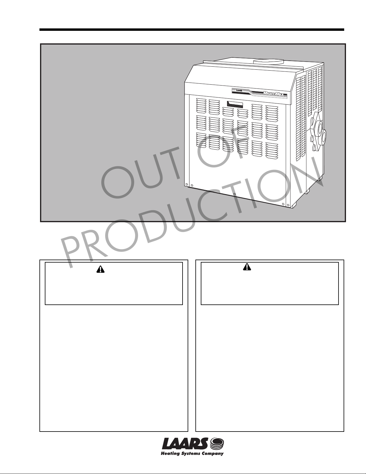
Mighty Max
Volume Water Heaters
Model VW
Sizes 320M - 400M
U.S. Reg. 1,901,192
Canada Reg. 433,882
OUT OF
FOR YOUR SAFETY: This product must be installed and serviced by a professional service technician,
qualified in hot water heater installation and maintenance. Improper installation and/or operation could
create carbon monoxide gas in flue gases which could cause serious injury, property damage, or death.
Improper installation and/or operation will void the warranty.
PRODUCTION
If the information in this manual is not
followed exactly, a fire or explosion may
result causing property damage, personal
injury or loss of life.
Do not store or use gasoline or other
flammable vapors and liquids in the vicinity
of this or any other appliance.
WHAT TO DO IF YOU SMELL GAS
• Do not try to light any appliance.
• Do not touch any electrical switch; do not
use any phone in your building.
• Immediately call your gas supplier from a
nearby phone. Follow the gas supplier's
instructions.
• If you cannot reach your gas supplier, call
the fire department.
Installation and service must be performed by
a qualified installer, service agency, or gas
supplier.
WARNING
Assurez-vous de bien suivres les instructions
données dans cette notice pour réduire au
minimum le risque d’incendie ou d’explosion ou
pour éviter tout dommage matériel, toute
blessure ou la mort.
Ne pas entreposer ni utiliser d’essence ni
d’autres vapeurs ou liquides inflammables dans
le voisinage de cet appareil ou de tout autre
appareil.
QUE FAIRE SI VOUS SENTEZ UNE ODEUR DE GAZ:
• Ne pas tenter d’allumer d’appareils.
• Ne touchez à aucun interrupteur. Ne pas vous
servir des téléphones dansle bâtiment où vous
vous trouvez.
• Appelez immédiatement votre fournisseur de
gaz depuis un voisin. Suivez les instructions
du fournisseur.
• Si vous ne pouvez rejoindre le fournisseur de
gaz, appelez le sservice des incendies.
L’installation et l’entretien doivent être assurés par
un installateur ou un service d’entretien qualifié ou
par le fournisseur de gaz.
AVERTISSEMENT
H0192500D
A subsidiary of BRADFORD WHITE Corporation
Page 2

Page 2
LAARS Heating Systems
TABLE OF CONTENTS
SECTION 1.
General Information
1.1 Introduction................................................... 3
1.2 Warranty ....................................................... 3
1.3 Technical Assistance .................................... 3
SECTION 2.
Installation Instructions
2.1 General Information ...................................... 3
2.2 Heater Placement ......................................... 4
2.3 Installation of Outdoor Heaters ..................... 4
2.4 Freeze Protection ......................................... 4
2.5 Installation of Indoor Water Heaters ............. 4
2.6 Gas Supply and Piping ................................. 5
2.7 Water System Piping .................................... 6
2.7.1 Water Chemistry ........................................... 6
2.7.2 Water Piping ................................................. 6
2.7.3 Pressure Buildup in Water System ............... 7
2.7.4 Temperature and Pressure Relief Valve ...... 7
2.7.5 Pump Requirements ..................................... 7
2.7.6 Combined Space Heating/Potable
Water Heating Systems ................................ 8
2.8 Venting and Combustion Air Information ...... 9
2.9 Top-to-Rear Vent Collar Conversion ............ 9
2.10 Venting ......................................................... 9
2.10.1 Vertical Venting - Category I......................... 9
2.10.2 Vertical Venting - Non Category I ................. 9
2.10.3 Horizontal Venting - Non Category I ........... 10
2.10.4 Side Wall Vent Terminal ............................. 10
2.11 Air for Combustion and Ventilation ............. 13
2.11.1 Air From Room ........................................... 13
2.11.2 Ducted Combustion Air .............................. 14
2.11.3 Conversion for Ducted Combustion Air ...... 14
2.11.4 Combustion Air Piping ................................ 14
2.12 Electrical Wiring .......................................... 15
PRODUCTION
OUT OF
SECTION 3.
Operation
3.1 Start Up Requirements ............................... 17
3.2 Hi-Limit Checkout ....................................... 18
3.3 Venturi and Gas Pressure
Regulator System ....................................... 18
3.3.1 Overall Operation ....................................... 18
3.4 To Start Up System .................................... 18
3.4.1 Setting Temperature Controls .................... 19
3.5 To Shut Down System ................................ 19
3.6 Venturi Adjustment - Natural Gas ............... 19
3.6.1 Pressure Measurement Port ...................... 19
3.6.2 Adjustment Procedure - Natural Gas.......... 19
3.6.3 Venturi Setup Procedure - Natural Gas ...... 21
3.7 Venturi Adjustment - Propane Gas ............. 21
SECTION 4.
Maintenance
4.1 General Instructions ................................... 22
4.2 Heater Exchanger ...................................... 22
4.2.1 Inspection of the Heat Exchanger .............. 23
4.2.1a External Heat Exchanger Inspection .......... 23
4.2.1b Internal Heat Exchanger Inspection ........... 23
4.2.1c Cleaning the Heat Exchanger - External .... 23
4.2.1d Cleaning the Heat Exchanger - Internal ..... 24
4.3 Gas and Electric Controls ........................... 24
4.4 Filter ........................................................... 24
4.4.1 Filter Function ............................................. 24
4.4.2 Filter Service .............................................. 24
SECTION 5.
Troubleshooting
5.1 Sequence of Operation .............................. 24
5.2 Venturi and Gas Pressure Regulator
System ....................................................... 26
5.3 Electrical Components ............................... 26
5.3.1 General Troubleshooting ............................ 26
5.3.2 Electrical Troubleshooting .......................... 27
SECTION 6.
Parts List for Mighty Max VW Heater
6.1 General Information .................................... 27
Page 3
Mighty Max Volume Water Heater
Page 3
SECTION 1.
General Information
1.1 Introduction
This manual provides installation, operation, and
maintenance instructions for the Mighty Max Volume
Water Heater, Model VW, Sizes 320M and 400M.
Review all application and installation procedures
completely before proceeding with the installation.
Consult the local factory representative or Laars
factory with any questions regarding this equipment.
Experience has shown that most operating problems
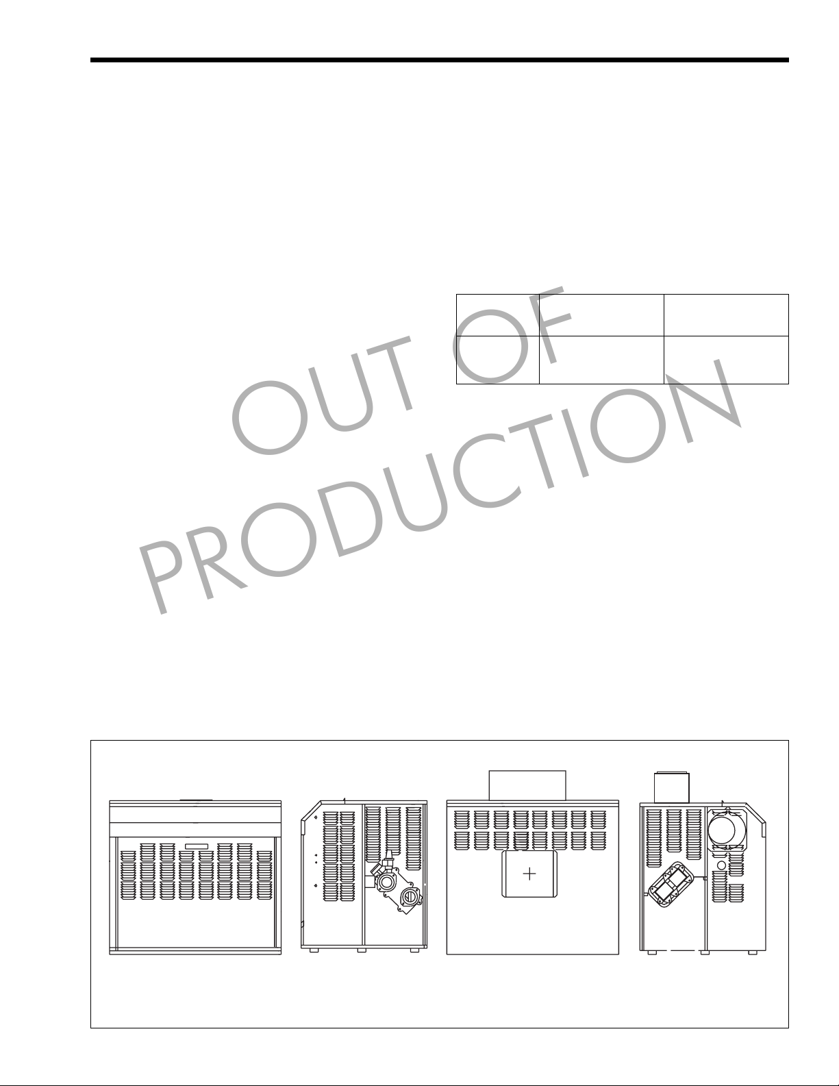
are caused by improper installation. The VW heaters
are offered in an indoor version and an outdoor
version (see Figure 1). Table 1 lists the input/output
ratings for each heater size.
The indoor version is convertible for outdoor use
with the installation of a conversion kit (see Section 6,
Parts List, for part number).
1.2 Warranty
The Mighty Max VW heaters are sold with a
limited factory warranty. Details are specified on the
back cover of this manual.
Make all warranty claims to an authorized Laars
representative or directly to the factory. Claims must
include the heater serial number and model number
(this information can be found on the rating plate),
installation date, and name of the installer. Shipping
costs are not included in the warranty coverage.
packages. Inspect everything for damage immediately
upon delivery, and advise the transporter of any
shortages or damage. Any such claims should be filed
with the transporter. The transporter will not accept a
claim from the shipper, Laars.
PRODUCTION
Some accessory items are shipped in separate
OUT OF
The warranty does not cover damage caused by
improper installation, operation, or field modification.
1.3 Technical Assistance
Consult the local factory representative or Laars
factory with any questions regarding the specification,
installation, and operation of Laars equipment. An
experienced technical support staff is ready to assist in
assuring the proper performance and application of
Laars products.
Heater Input Output
Size BTU/h kW BTU/h kW
320M 320,000 94 272,000 80
400M 399,000 117 339,150 99
Table 1. Input/Output Ratings.
SECTION 2.
Installation Instructions
2.1 General Information
Install the Mighty Max VW heater in accordance
with the procedures in this manual (or the Laars
warranty may be voided), local codes, and ordinances.
In the absence of such codes, install the heaters in
accordance with the latest edition of the National Fuel
Gas Code, ANSI Z223.1/National Fire Protection
Association (NFPA) 54. In Canada, the installation
must be in accordance with CSA B149.1 and local
codes. The authority having jurisdiction may require
the installation be in accordance with the American
Society of Mechanical Engineers (ASME) Safety
Codes for Controls and Safety Devices for
INDOOR OUTDOOR
Front Side
(Water Connections)
Figure 1. Mighty Max VW Heater Configuration.
Rear Side
(Opposite Water
Connections)
Page 4
Page 4
LAARS Heating Systems
Automatically Fired Heaters, CSD-1. In Canada, other
standards may apply. Any changes to the heater, its
gas controls, gas orifices, or wiring may void the
warranty. If field conditions require change, consult
the factory.
The Mighty Max VW heater is designedcertified for installation on a combustible floor, if a
non-combustible base is first placed under the heater.
Do not install the heater directly on carpeting
without placing a metal or wood panel between the
carpeting and the heater. The metal or wood panel
must extend beyond the full width and depth of the
heater by at least 3 inches (76.2mm) in all directions.
If the heater is installed in a carpeted alcove, the entire
floor of the alcove must be covered by the
metal or wood panel. The panel must be strong enough
to carry the total weight of the heater and all piping,
pumps, and any other equipment attached to the
heater.
Clearance Indoor Outdoor
From Combustibles Inches mm Inches mm
Top 18 457 Unobstructed
Water Conn. Side 12 305 12 305
Opposite side 6 152 6 152
Front Alcove Unobstructed
Rear 6 152 6 152
Vent *6
Flooring Combustible Combustible
Service clearance = 24 inches (610mm) at front of heater.
*1" (25mm) if double wall vent is used.
Table 2. Minimum Heater Clearances
PRODUCTION
From Combustible Surfaces.
OUT OF
* 152 —
2.2 Heater Placement
Locate the heater to provide adequate clearances
on all sides for maintenance and inspection. There
must also be minimum distances maintained from
combustible surfaces (see Table 2). The heater must be
isolated or otherwise protected from any source of
corrosive chemical fumes, such as trichlorethylene,
perchlorethylene, chlorine, etc. Install the heater so
that the gas ignition system components are protected
from water (drippings, spraying, rain, etc.) during
operation and service.
2.3 Installation of Outdoor Heaters
CAUTION
Outdoor installations are not recommended in
areas where the danger of snow blockage exists.
AVERTISSEMENT
L’eau chaude peut brûler ! L’eau chaude peut
causer des brûlures du troisième degré en 6
secondes à 60°C (140°F) et en 30 secondes à
54°C (130°F).
1. Locate the heater to provide at least the
minimum clearances as listed in Section 2.2,
“Heater Placement.” VW heaters require an
outdoor terminal kit when installed outdoors (see
Section 6, Parts List).
2. Do not locate the heater in an enclosure or throughwall recess. Avoid locations where wind deflection
off structures might cause down-draft. When such
wind conditions are possible, locate the heater at
least 3 feet (.9m) from structures.
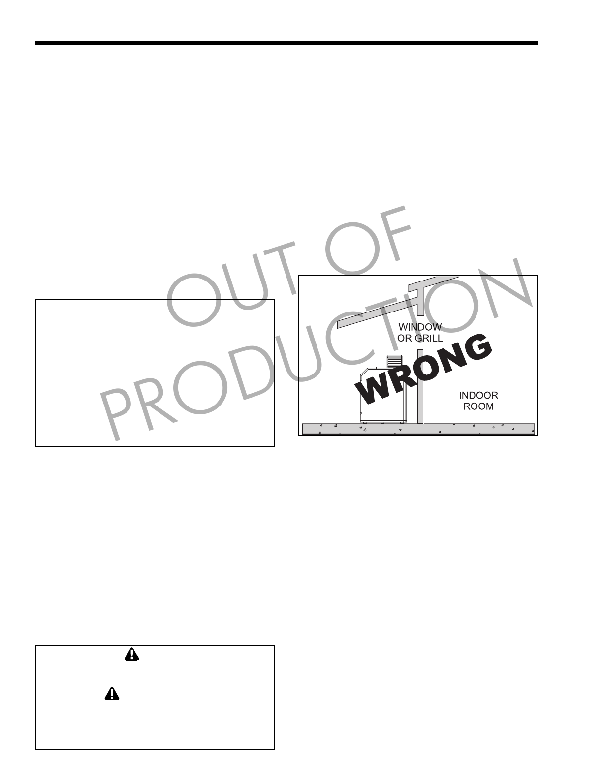
3. Never install the heater under any kind of roof
overhang. Do not locate the heater below or
adjacent to any doors, windows, louvers, grills, etc.
which communicate in any way with an inhabited
area of a building, even though such
communication might be through another structure
such as a garage or utility room (see Figure 2).
Figure 2. Incorrect Installation of Boiler.
2.4 Freeze Protection
Although Mighty Max VW heaters are design-
certified for outdoor installations, such installations
are not recommended in areas subject to freezing
temperatures, unless proper precautions are taken.
Power outage, interruption of gas supply, failure
of system components, activation of safety devices,
etc., may prevent a heater from firing. Any time a
heater is subjected to freezing conditions, and the
heater is not able to fire, and/or the water is not
able to circulate, there is a risk of freezing in the
heater or in the pipes in the system. When water
freezes, it expands. This can result in bursting of pipes
in the system, or damage to the heater, which could
result in leaking or flooding conditions.
Contact the local factory representative or Laars
for additional information.
2.5 Installation of Indoor Water Heaters
Combustion Air Supply and Ventilation:
There are a variety of options available to the
installer when it comes to venting and combustion air;
venting can be vertical or horizontal, it can originate at
Page 5
Mighty Max Volume Water Heater
Distance from Gas Meter or Last Stage Regulator
0-100 feet 100-200 feet 200-300 feet
0-30m 30-60m 60-90m
Natural Propane Natural Propane Natural Propane
Size in. mm in. mm in. mm in. mm in. mm in. mm
320M 1.25 32 1.25 32 1.50 38 1.25 32 1.50 38 1.50 38
400M 1.25 32 1.25 32 1.50 38 1.25 32 2.00 51 1.50 38
Notes: 1. These numbers are based on 1/2 inch (13mm) water column pressure drop.
2. Check supply pressure and local code requirements before proceeding with work.
3. Pipe fittings must be considered when determining gas pipe sizing.
Table 3. Natural Gas and Propane, Pipe Size Requirements.
Page 5
the top of the heater or the back, and combustion air
can be obtained from the room where the heater is
installed or ducted directly to the heater from outdoors
(see Sections 2.8 through 2.11 for details).
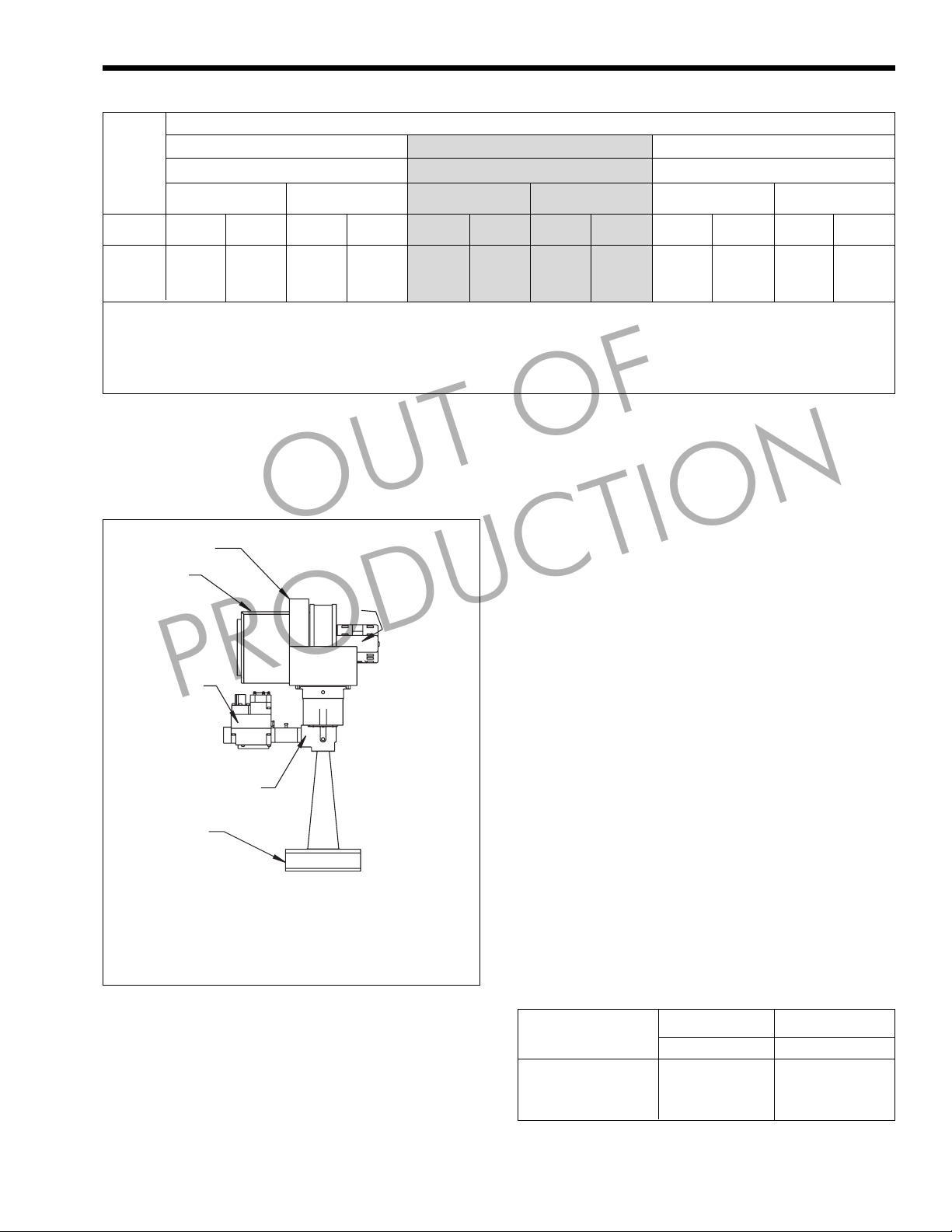
Air Shutter
Enclosure
Filter
Housing
Automatic,
Regulator
and
Redundant
PRODUCTION
Gas Valve
Venturi
Mixture
Plenum
NOTE: The above diagram is a representation, actual venturi
assembly may vary depending upon heater size.
OUT OF
Blower
Motor
SIZES:
320M, 400M
with CSA B149.1 and all local codes that apply
(see Figure 3 for heater gas valve arrangement).
2. Check the rating plate to make sure the heater is
fitted for the type of gas being used. Laars
heaters are normally equipped to operate below a
2000 foot (610m) altitude. Heaters equipped to
operate at high altitudes have appropriate
stickers or tags attached.
3. The figures in Table 3 should be used to size the
gas piping from the gas meter to the heater.
Check local codes for BTU/h capacity required.
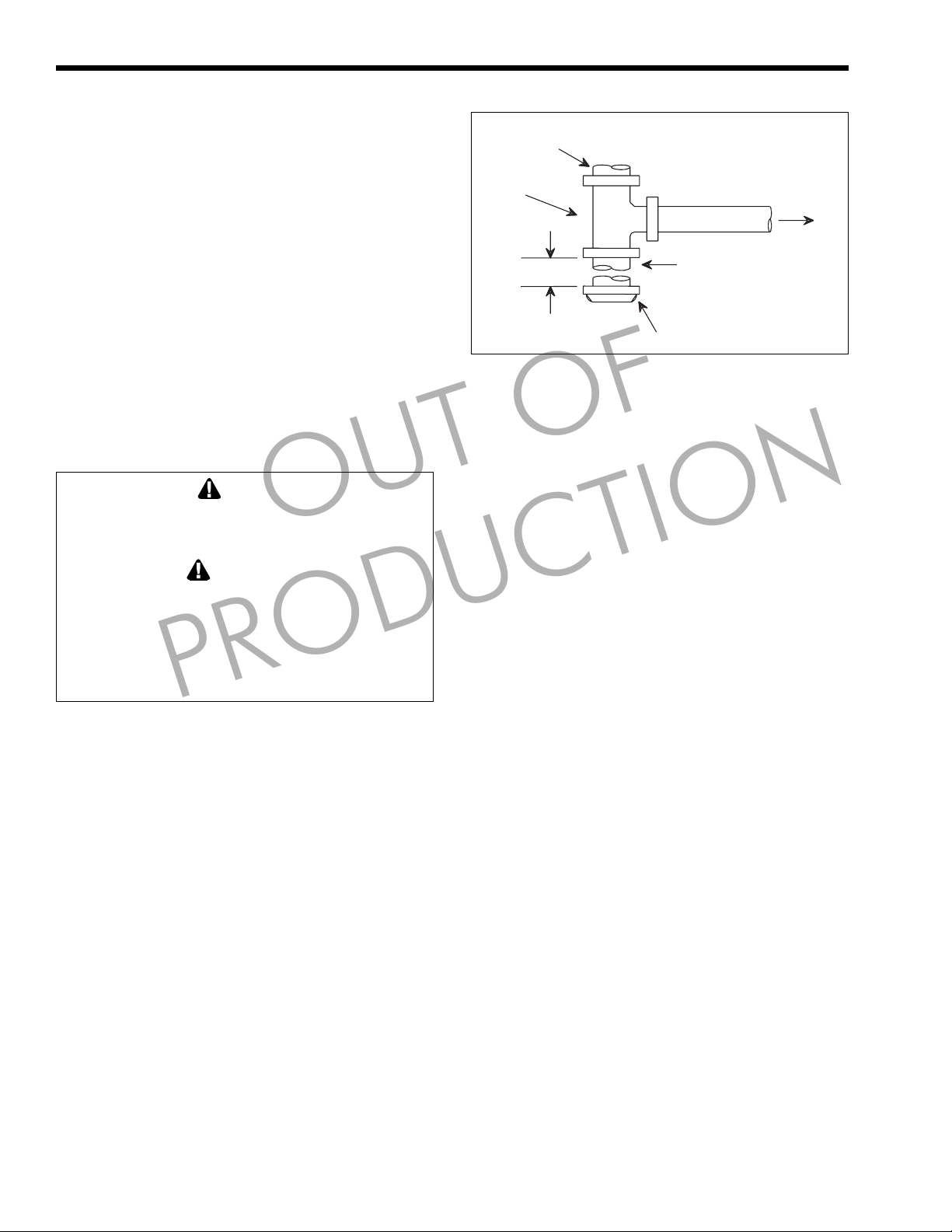
4. Install a sediment trap (drip leg) ahead of the gas
controls (see Figure 4). Fit the trap with a
threaded cap which can be removed for cleaning.
5. When required by code, install a second manual
gas shutoff valve. Do not remove manual shutoff
valve supplied with the heater.
6. Disconnect the heater and its individual shutoff
valve from the gas supply piping system during
pressure testing of the system at pressures higher
than 1/2 psi (3.5 kPa). Isolate the heater from the
gas supply piping system by closing its
individual manual gas shutoff valve during any
pressure testing of the gas supply piping system
at test pressures equal to or less than 1/2 psi
(3.5 kPa).
7. Gas supply pressures to the heater are listed in
Table 4.
Figure 3. Heater Gas Valve Arrangement.
2.6 Gas Supply and Piping
Review the following instructions before
continuing the installation.
1. Gas piping installation must be in accordance
with the latest edition of ANSI Z223.1/NFPA 54.
In Canada, the installation must be in accordance
Supply Pressure Natural Gas Propane Gas
Water Column
Minimum 5 127 9 229
Maximum 9 229 14 356
Table 4. Gas Supply Pressure Requirements.
in. mm in. mm
Page 6
Page 6
LAARS Heating Systems
NOTE: The heater and all other gas appliances
sharing the heater gas supply line must be firing at
maximum capacity to properly measure the inlet
supply pressure. Low gas pressure could be an
indication of an undersize gas meter and/or
obstructed gas supply line.
8. Do not exceed the maximum inlet gas pressures
specified. Excessive pressure will result in
damage to the heater's gas controls. The
minimum pressures specified are for gas input
adjustment.
9. The correct differential gas pressure is stamped
on the rating plate. The regulator is preset at the
factory, but may need adjustment for altitude per
Section 3.
10. Before operating the heater, test the complete gas
supply system and all connections for leaks using
a soap solution.
CAUTION
Since some leak test solutions (including soap and
water) may cause corrosion or stress cracking,
rinse the piping with water after testing.
ATTENTION
La commande d’allumage fonctionne sur un
courant de 120V. Pensez-y lorsque vous travaillez
sur le chauffe-eau et prenez soin d’éviter tout
contact avec des pièces branchées sur le courant
qui causeraient une électrocution, conduisant à des
dégâts matériels, aux blessures voire à la mort.
OUT OF
PRODUCTION
Gas Supply
Inlet
Te e
Fitting
3 in.
(76mm) Min.
Figure 4. T-Fitting Sediment Trap Installation.
up a heat exchanger tube-cleaning maintenance
schedule to prevent heat exchanger tube cracking and
wear. Not fixing the condition may cause serious
damage to the heater and the water system.
Scaling is a layer on the inner surface of the heat
exchanger tubes which restricts the flow of water.
Scale can be any color or texture, smooth or rough,
granular or amorphous. Erosion is usually identified
by pitting, cavitation, ridges and “islands” on the inner
surfaces of the heat exchanger tubes. If this is caused
by extremely soft water, or a water softener in the
system, the internal copper surfaces will be very
shiny. Other chemicals, such as chlorine or chlorides
in the water, will cause dark patches of erosion.
NOTE: Laars does not warrant heat exchangers
damaged by scaling, corrosion, or erosion.
Nipple
Cap
To Equipment
Inlet
2.7 Water System Piping
2.7.1 Water Chemistry
Laars equipment is designed to be used in a
variety of water conditions. The water velocity in the
heat exchanger tubes is kept high enough to prevent
scaling from hard water, yet low enough to avoid
erosion by soft water. The water in 95 percent of the
urban centers in the United States is compatible with
this equipment, but in some areas a water supply will
contain a large quantity of scaling chemicals or the
water may be extremely soft or erosive. In rare
situations the water will contain both scaling
chemicals and erosive chemicals such as calcium or
sodium chloride. These conditions may be caused by
well water or a nearby pumping station, and the
particular condition may not be characteristic of the
entire city water system.
NOTE: It is possible to have hard and soft water in
the same city. Check with the local water company.
If an installer sees damage to any water handling
equipment at the installation site, it should be repaired
as soon as possible to help reduce maintenance costs.
If there is erosion, resize the pump to reduce water
velocity before the tube ruptures. If scaling is bad, set
2.7.2 Water Piping
Minimum inlet water temperature is 120°F
(49°C).
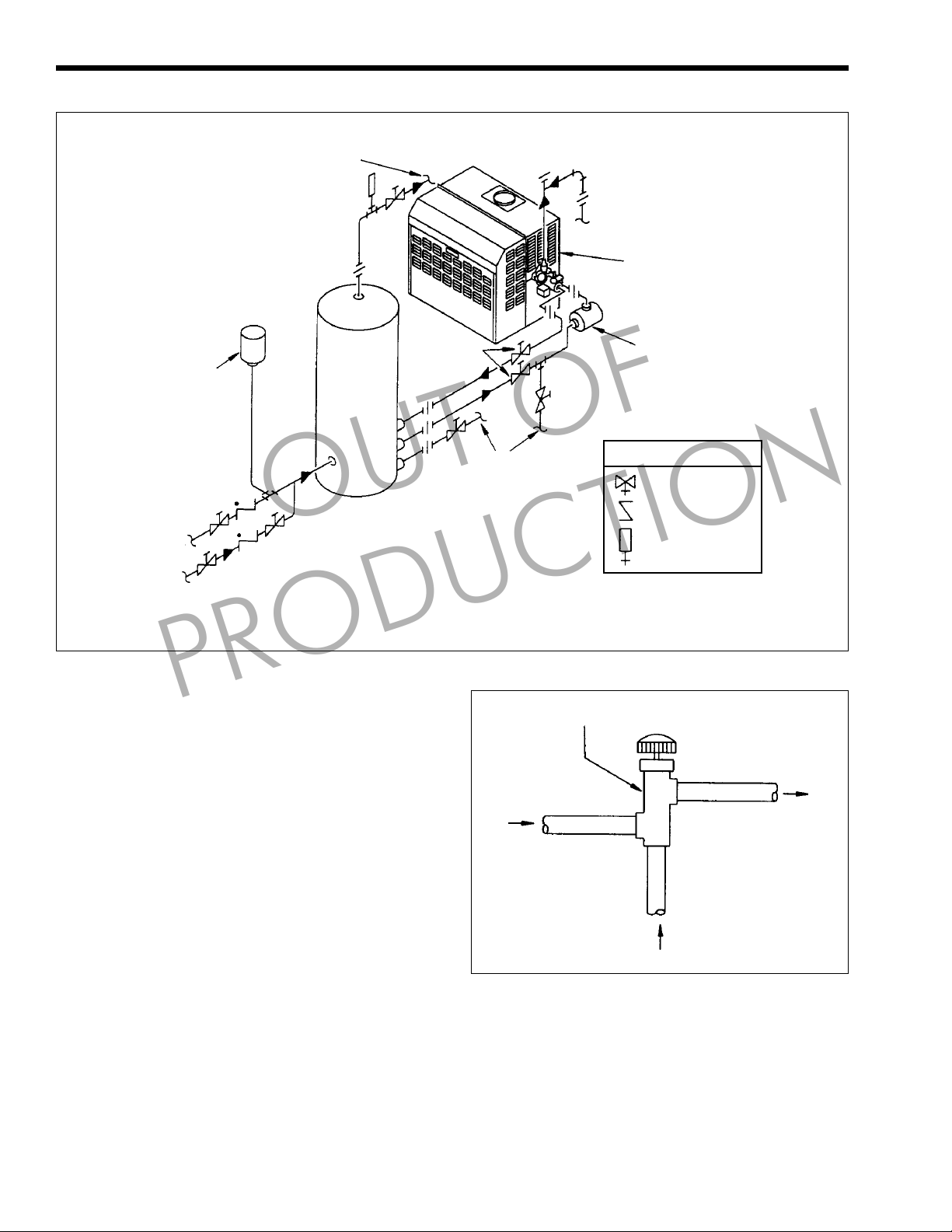
VW heaters are intended for heating large
volumes of water at constant flow rates, usually for
storage in a tank. Heaters in this type of application
are sometimes called circulating water heaters.
Figure 5 shows the VW heater with tank and two
pumps. One pump (recirculation) only circulates the
hot water through the building plumbing. The other
pump (heater) circulates water between the tank and
the heater. This heater circulating pump is essential for
proper operation of the heater (see Section 2.7.5).
The heater circulating pump must be sized to
provide enough flow to prevent damage to the heat
exchanger, and must handle the hardness or softness
of the water being heated. Generally, hard water must
be pumped at higher velocity; however, soft water will
erode holes in the heat exchanger tubing if pumped
too fast.
The Mighty Max VW heater comes standard
with copper tubes, but in areas where the water supply
is soft or corrosive, the heat exchanger should be
factory ordered with cupronickel tubes. Consult the
Page 7
Mighty Max Volume Water Heater
Page 7
local factory representative or Laars factory for
additional information.
2.7.3 Pressure Buildup in Water System
The water utility supply meter may contain a
check valve, back flow preventer, or water pressure
reducing valve. This will create a closed water supply
system. Contact the water supplier or local plumbing
inspector on how to control this situation.
During the heating cycle of the heater, the water
expands creating a pressure buildup in the water
system. The pressure and temperature relief valve may
discharge hot water under these conditions, causing a
loss/waste of energy and a buildup of lime on the
relief valve seat.
NOTE: Do not plug the relief valve.
There are two methods to prevent the water
heater pressure relief valve from discharging hot water
in a closed water system:
1. Install a pressure relief valve on the cold water
supply line. Make sure that the discharge of this
valve is directed to an open drain and protected
from freezing.
2. Install a properly sized thermal expansion tank
on the cold water supply line.
2.7.4 Temperature and Pressure Relief
Valve
For protection against excessive pressure, the
water heater is equipped with a pressure relief valve.
storage vessel, a temperature and pressure relief valve
must be installed on the storage vessel. The
temperature and pressure relief valve must be designcertified by a nationally recognized testing laboratory
that maintains periodic inspection of listed equipment
or materials, in accordance with the requirements of
the standard for Relief Valves for Hot Water Supply
Systems, ANSI Z21.22 / CSA 4.4.
have a BTU/h (kW) capacity rating that is greater than
the BTU/h (kW) input of the water heater. The
temperature and pressure relief valve must be marked
with a maximum working pressure not to exceed the
maximum working pressure shown on the rating plate
of the water heater, or the maximum working pressure
of the separate storage vessel, whichever is the lower
pressure. The temperature and pressure relief valve
must have a maximum working temperature not to
exceed 210°F (99°C).
temperature and pressure relief valve and the storage
vessel.
quantities should circumstances demand.
PRODUCTION
When the water heater is connected to a separate
The temperature and pressure relief valve must
Do not place any shutoff valves between the
The relief valves discharge water in large
OUT OF
The discharge pipe:
1. Must not be connected directly to a drain. The
Discharge pipe must terminate 6 inches (152mm)
above a floor drain or external to the building. If
the discharge pipe is not directed to a drain or
other suitable means, the water flow may cause
property damage.
2. Must not be smaller than the pipe size of the
relief valve.
3. Must be of material capable of withstanding
210°F (99°C) without distortion.
4. Must be installed to allow complete drainage of
both the relief valve and discharge pipe.
5. Must not have any valve between the relief valve
and the end of the discharge pipe.
Do not thread, cap, plug, or block the end of the
discharge pipe. Do not install a reducing coupling or
other restrictions in the discharge pipe.
WARNING
Hot water can scald! Hot water can produce third
degree burns in 6 seconds at 140°F (60°C) and in
30 seconds at 130°F (54°C).
ATTENTION
Au moment de l’entretien des commandes, mettez
des étiquettes sur tous les fils avant de les
débrancher. Des erreurs de câblage peuvent
causer un fonctionnement inadéquat et dangereux.
Vérifier que tout fonctionne bien après votre
entretien.
Manually operate the relief valves at least once a
year. To prevent water damage, discharge pipe must
terminate at an adequate drain. Standing clear of the
outlet (discharge water may be hot), lift and release
the lever handle on the relief valve to make the valve
operate freely.
2.7.5 Pump Requirements
Table 5 specifies water flow rates for the
Mighty Max VW heaters, and the pumping head
required for typical piping configurations. Table 5
allows for 30 feet (9.1m) of piping and typical
fittings (see Figure 5). Piping with a shorter length or
larger diameter may reduce the head requirement and
pump power consumption. Contact a Laars
representative for assistance.
The correct flow rate can be verified by checking
the temperature rise of water as it passes through the
heater. To check the temperature rise, measure the
difference in water temperature between the heater
inlet and outlet to determine flow. For example: If a
Size 320M VW heater is installed and normal water is
used; the inlet water temperature is 160°F (71°C); the
outlet water temperature is 171°F (77°C). Then there
is a 11°F (6°C) degree temperature rise. Per Table 3,
Page 8
Page 8
LAARS Heating Systems
Hot Water
To Bldg.
To Drain
Mighty Max
VW Heater
Thermal
Expansion
Tank
Cold
Water
Hot Water
Return From
Bldg.
NOTE: Intermittent pump must be used with EM2 and remote temperature control.
Figure 5. Water Piping Diagram.
this is essentially correct for normal water. If a higher
temperature rise is measured, flow must be increased
by changing the piping or pump.
2.7.6 Combined Space Heating/Potable
When using the Mighty Max VW heater as a
source of heat for a combined space heating/potable
water heating system, be sure to follow the
instructions of the space heating system.
Do not use water piping, fittings, valves, pumps,
and any other components which are not compatible
with potable water.
Do not connect the heater, which will be used to
supply potable water, to any heating system or
components previously used with a nonpotable water
heating system.
Do not add boiler treatment or any chemicals to
the heating system piping, since the piping contains
water for potable use.
Do not use solder containing lead in the potable
water lines.
If the space heating system requires water
temperatures greater than the water temperature for
potable hot water use, a tempering valve (see Figure 6)
PRODUCTION
Water Heating Systems
OUT OF
Conventional
Tank
Service
Valve
To Drain
Mixing Valve
Hot Water
From Water Heater
or Storage Tank
Figure 6. Installation of Tempering Valve.
or other means should be installed in the potable hot
water supply line to limit the risk of scald injury.
Some jurisdictions may require a backflow
preventer in the cold water line. In such cases, the
temperature and pressure relief valve may discharge
water due to expansion. An expansion tank approved
for potable water will eliminate this condition. Follow
the manufacturer's instructions for installation of the
expansion tank.
Pump
KEY
Valve
Check Valve
Gauge
Out Mixed Water
For Potable Use
Cold Water
Supply
Page 9

Mighty Max Volume Water Heater
Page 9
2.8 Venting and Combustion Air
Information
Provisions for venting and supply of air for
venting and combustion must be done in accordance
with these instructions and applicable requirements of
the latest edition of ANSI Z223.1/NFPA 54. In
Canada, installation must be in accordance with CSA
B149.1, and applicable local codes.
There are a variety of ways to provide venting
and combustion air for the VW heater (see Figure 7).
The Mighty Max VW heater is certified as a true
direct vent unit when installed according to the
instructions for horizontal venting and ducted
combustion air. This can be done even if the runs are
vertical.
2.9 Top-to-Rear Vent Collar Conversion
The Mighty Max VW heater is shipped with the
vent collar on top of the heater. Follow this procedure
to convert it for rear connection (see Figure 8).
1. Remove the adapter plate from the top panel.
2. On the heater jacket, remove the top panel and
ease its lip from under the edge of the bonnet to
gain access to the flue collector.
3. Remove the vent collar/stack from the flue
collector. Do not damage the vent collar/stack
during removal.
4. Remove the blank plate from the rear of the
heater jacket.
5. Remove the blank plate from the rear section of
the flue collector. Be careful not to lose the
PRODUCTION
insulation attached to the plate.
6. Apply high temperature sealant and install the
blank plate (previously removed from the rear
section of the flue collector) on top of the flue
collector.
7. Install the blank plate (previously removed from
the rear of the boiler jacket) over the stack
opening on the top panel of the boiler.
OUT OF
8. Apply high temperature sealant (see Table 6) to
vent/collar stack and install on the rear of the
flue collector.
9. Slip the adapter plate over the vent collar/stack
and install it onto the rear heater jacket (see
Figure 8).
2.10 Venting
Venting must be in accordance with these
instructions and applicable requirements of the latest
edition of ANSI Z223.1/NFPA 54. In Canada,
installation must be in accordance with the latest
edition of CSA B149.1, and applicable local codes.
2.10.1 Vertical Venting - Category I
The Mighty Max VW heater has a “fan-assisted”
combustion system, so vertical vents must be installed
in accordance with the special code requirements for
Category I - Fan-Assisted Appliances. These
requirements can be found in the latest edition of
ANSI Z223.1/NFPA 54; Chapters 10 & 13 may be
referenced. In Canada, CSA B149.1 should be used
for guidance. These codes permit installation as a
single appliance or in combination with other
Category I appliances. However, there are very
important requirements for minimum and maximum
vent diameter and length. Make sure vertically-vented
installations comply with these codes.
NOTE: If a vent cannot be installed in accordance with
the requirements of these codes, it must be installed
as a horizontal vent, even if it is mainly vertical.
2.10.2 Vertical Venting - Non-Category I
When venting does not meet the code
requirements for Category I - Fan-Assisted Vertical
Vents, it can develop positive pressure. Such venting
must be installed in accordance with this section or
Section 2.10.3.
Soft or Normal Water Hard Water
Pipe Size Flow Headloss Temp, Rise Flow Headloss Temp. Rise
Model in. mm gpm L/m ft. m °F °C gpm L/m ft. m °F °C
0320M 1.5 38 51 193 25.9 8 10.5 6 68 257 46.0 14 7.9 4
2.0 51 51 193 13.9 4 10.5 6 68 257 24.7 8 7.9 4
0400M 1.5 38 51 193 26.0 8 13.1 7 68 257 46.3 14 9.8 5
2.0 51 51 193 14.1 4 13.1 7 68 257 25.0 8 9.8 5
Notes: 1. Pressure dop includes allowance for 30 feet 9.1m of piping and normal fittings. If piping is shorter or of larger
diameter, pump power may be reduced substantially. Contact Laars Representative for assistance.
2. Heaters for soft water application should be equipped with cupronickel heat exchangers.
Soft Water: 0 to 7.5 Grains/gallon
Normal Water: 7.5 to 17 Grains/gallon
Hard Water: More than 17 Grains/gallon
3. The temperature rise across the heater should never exceed 20°F (11°C). Minimum inlet water temperature is
120°F (49°C).
Table 5. Pump Requirements for Mighty Max VW Heaters.
Page 10
Page 10
Term Description
Pipe Must comply with UL Standard 1738
such as type 29-4C stainless steel
Joint Sealing Follow vent manufacturer's
instructions
Insulation Recommended, but not required,
minimum R5 with protective cover
Table 6. Required Horizontal Venting Material.
The following requirements must be used for
Non-Category I venting:
1. Laars specified vent pipe material (Table 6) and
sizes (Table 7).
2. Pipe insulation and sealing tape.
3. Routing vent pipe through spaces which, except
for the terminal, remain above 60°F (16°C)
during heater operation.
OUT OF
2.10.3 Horizontal Venting - Non-Category I
When venting is horizontal, or cannot meet the
code requirements for Category I - Blower-Assisted
Vertical Vents, it can develop positive pressure and
must be installed in accordance with this section.
The following requirements must be used for
Horizontal Venting - Non-Category I:
1. Laars specified vent piping materials
(Table 6) and sizes (Table 7).
2. Laars side wall vent hood.
3. Pipe insulation and sealing tape.
4. Routing vent pipe through spaces which, except
for the terminal, remain above 60°F (16°C)
during heater operation.
2.10.4 Side Wall Vent Terminal
The side wall vent hood must be used when the
heater is vented through a side wall. It provides a
means of installing vent piping through the building
wall, and must be located in accordance with ANSI
Z223.1/NFPA 54 and applicable local codes. In
Canada the installation must be in accordance with
CSA B149.1 and local applicable codes (see Figure 9).
Consider the following when installing the terminal:
1. Locate the vent terminal so that it will not be
damaged by pedestrians and other traffic, and so
the discharge is not objectionable. The National
Fuel Gas Code requires a through-wall vent
terminal be at least 7 feet (2.1m) above grade if
located at a public walkway.
2. Locate the vent terminal so that vent gases
cannot be drawn into air conditioning system
inlets. The National Fuel Gas Code requires that
PRODUCTION
LAARS Heating Systems
it be at least 6 feet (1.8m) above any such inlet
that is within 10 feet (3m).
3. Locate the vent terminal so that vent gases
cannot enter the building through doors,
windows, gravity inlets or other openings. The
National Fuel Gas Code requires that it be
located at least 4 feet (1.2m) below, 4 feet (1.2m)
horizontally from, or 3 feet (0.9m) above such
openings.
4. Locate the vent terminal so that it cannot be
blocked by snow. The National Fuel Gas code
requires that it be at least 12 inches (305mm)
above grade, but the installer may determine it
should be higher depending on local conditions.
5. Locate the terminal so the vent exhaust does not
settle on building surfaces and other nearby
objects. Vent products may damage such
surfaces or objects. But the actual construction of
the vent terminal and the flow of vent products
must not be altered.
6. Locate the terminal at least 6 feet (1.8m)
horizontally from any gas or electric metering,
regulating, or relief equipment, or building
opening.
Mighty Max units are Category I fan-assisted
when vented vertically and adhering to all applicable
codes. Mighty Max units are not allowed to be vented
into a common horizontal vent system, unless a
properly-sized vent fan is used, and the common vent
system is properly designed by the vent fan
manufacturer or a qualified engineer.
When common venting Mighty Max fan-assisted
heaters with other appliances through one shared
vertical duct called a “common vent”, special care
must be taken by the installer to ensure safe operation.
In the event that the common vent is blocked, it is
possible, especially for fan-assisted devices, to vent
backwards through non-operating appliances sharing
the vent, allowing combustion products to infiltrate
occupied spaces. If the appliances are allowed to
operate in this condition, serious injury or death may
occur.
WARNING
Operation of appliances with a blocked common
vent may lead to serious injury or death. Safety
devices must be implemented to prevent blocked
common vent operation. If safe operation of all
appliances connected to a common vent cannot be
assured, including prevention of spillage of flue
gasses into living spaces, common venting should
not be applied, and appliances should each be
vented separately.
Page 11

Mighty Max Volume Water Heater
Category I
Vertical Venting (Category I)
Screen Provided
On Vertical Intake
Air Terminal
Combustion Air In
Through Louvers
Page 11
For vertically ducted combustion air:
• Combustion air intake must
terminate at least 3 feet (0.91m)
lower than vent termination, if it is
located within a 10 foot (3.05m)
radius.
• Combustion air intake must be at
least 1 foot (0.3m) above roof top
and normal snow levels.
OUT OF
Vertical Venting
with Ducted
Combustion Air
Non-Category I
PRODUCTION
Exhaust Terminal Detail
Horizontal Venting
Any Vent Which Does Not Meet
Category I Combustion Air
Through Louvers
Side View
Horizontal
Intake Terminal Detail
(Combustion Air)
Wall
Horizontal Venting
Ducted Combustion Air
(Certified As Direct Vent)
NOTE: All views are shown
from rear of heater
Figure 7. Venting and Combustion Air Options.
Wall
Side View
Page 12

Page 12
LAARS Heating Systems
Vent
Collar/Stack
Blank Plate
(Heater
Jacket)
Adapter Plate
Top Panel
1. Removal of Blank Plate and Adapter
Plate From Heater
OUT OF
Blank Plate On
Heater Jacket
Top Panel
Blank Plate On
Flue Collector
3. Blank Plate Placement
Over Stack Top Opening
Blank Plate
(Flue
Collector)
Vent
Collar/Stack
PRODUCTION
2. Removal of Blank Plate From
Rear of Flue Collector
Figure 8. Top-To-Rear Vent Collar.
Heater
Size of Elbows Vent Terminal Combustion Air
320M 6 152 50 15 5 D2004500 20260701
400M 7 178 50 15 5 D2004600 20260702
IMPORTANT: Maximum pipe length allowed is 50 feet (15m), regardless of the number of elbows. Maximum number of elbows allowed is 5.
Vent pipe minimum clearance from combusible surfaces is 6 inches (152mm).
Pipe Diameter Max Pipe Length
in. mm ft. m
Max No. Side Wall Side Wall
4. Connecting Vent Collar/Stack
to Flue Collector
Part Number Terminal Part Number
Table 7. Vent Piping Specifications (Combustion Air Exhaust).
Page 13

Mighty Max Volume Water Heater
Page 13
It is for this reason that, in addition to following
proper vent sizing, construction and safety
requirements from the National Fuel Gas Code, ANSI
Z223.1 or in Canada, from CSA B149.1 as well as all
applicable local codes, it is required that installers
provide some means to prevent operation with a
blocked common vent. It is suggested that a blocked
vent safety system be employed such that if the switch
from one appliance trips due to excessive stack spill or
backpressure indicating a blocked vent condition, that
all appliances attached to the vent be locked out and
prevented from operating. (Note that the Mighty Max
unit is equipped with a blocked vent safety (pressure)
switch, as shipped.) As an additional precaution, it is
recommended that a Carbon Monoxide (CO) alarm be
installed in all enclosed spaces containing combustion
appliances. If assistance is required in determining
how a blocked vent safety system should be connected
to a LAARS product, please call Applications
Engineering at (603) 335-6300.
Refer to the installation and operating
instructions on all appliances to be common vented for
instructions, warnings, restrictions and safety
requirements. If safe operation of all appliances
connected to a common vent cannot be assured,
including prevention of spillage of flue gasses into
living spaces, common venting should not be applied,
and appliances should each be vented separately.
OUT OF
2.11Air for Combustion and Ventilation
The heater requires air for combustion and the
space around the heater requires ventilation.
Combustion air can be provided by standard practices
as specified in the installation codes (ANSI Z223.1/
NFPA 54, in Canada, CSA B149.1 and local
applicable codes), or ducted directly to the heater.
Ventilation air must be provided in either case.
2.11.1 Air From Room
Standard requirements for providing air for
combustion and ventilation are provided by ANSI
Z223.1/NFPA 54 and in Canada by CAN/CSA
B149.1. These codes require passages be provided for
air flow into the space where the heater is installed.
The size of these passages is based on the firing rate of
the heater and the path of air flow into the space. In
general, installations which take air from inside the
building require larger passages than those which take
air directly through an outside wall.
Failure to provide adequate combustion and
ventilation air can cause the heater, and other
appliances occupying the same space, to operate with
dangerous and inefficient combustion, and can cause
overheating of the space. Be sure to provide air
passages in accordance with ANSI Z223.1/NFPA 54,
in Canada, CSA B149.1 and local applicable codes,
PRODUCTION
Vent Terminal
4 ft. (1.2 m) Min.
Vent Terminal
3 ft. (0.9 m) Min.
4 ft. (1.2 m) Min.
Vent
Terminal
12 in. (305mm) Min.
Less Than
10 ft. (3.0 m)
6 ft. (1.8 m) Min.
Grade
Forced Air
Inlet
Figure 9. Building Exterior.
Page 14

Page 14
and do not permit any other condition, such as an
exhaust blower, to affect the air supply for combustion
and ventilation.
2.11.2 Ducted Combustion Air
Combustion air can be brought directly to the
heater through a duct of suitable size and length (see
Table 7). Consult Laars about installations not covered
by Table 7.
Combustion air must be taken from out-of-doors
by means of the Laars side wall terminal.
Locate the terminal within 10 feet (3m) of the
heater vent exhaust terminal, but no closer than 3 feet
(0.9m) (centerline distance).
Do not locate the air inlet terminal near a source
of corrosive chemical fumes (e.g., cleaning fluid,
chlorine compounds, etc.). Locate it so that it will not
be subject to damage by accident or vandalism. It must
be at least 7 feet (2.1m) above a public walkway.
Use single-wall galvanized pipe for the
combustion air duct. Route the duct to the heater as
directly as possible. Seal all joints with tape. Provide
adequate hangers. The heater must not support the
weight of the combustion air duct.
When combustion air is ducted to the heater,
other provisions must be made for heater room
ventilation. VW heaters lose less than 1 percent of
their input rating to the room, but other heat sources
may be present. Provide enough ventilation air to meet
comfort specifications. Make sure the ventilation air is
not directed at the heater, water piping or other
equipment which could be damaged by freezing.
PRODUCTION
OUT OF
Louvered
Plate
Adapter
Plate
LAARS Heating Systems
Inlet
Pipe
2.11.3 Conversion for Ducted
Combustion Air
The conversion to ducted combustion air
requires the parts listed in Table 8. Follow these
procedures to convert the heater (see Figure 10):
Boiler Size Assembly Number
320 20258101
400 20258102
Table 8. Combustion Air Assembly.
1. Remove the louvered plate from the left side of
the heater.
2. Remove the adapter plate from the shipping
container.
3. Install the blower motor housing collar in gasket.
4. Slip one end of the inlet pipe over the collar on
the adapter plate.
5. Slide the inlet pipe and adapter plate into the
heater opening until the pipe is aligned with the
blower motor.
Ducted Combustion
Air Pipe
Figure 10. Ducted Combustion Air Conversion.
6. Slip the end of the inlet pipe over the blower
motor housing collar.
7. Secure the adapter plate to the side of the heater
with the 4 screws.
2.11.4 Combustion Air Piping
Run piping of the appropriate size between the
air intake terminal and the heater (see Table 7). Table
9 lists the materials for piping the heater.
Page 15

Mighty Max Volume Water Heater
Page 15
Term Description
Pipe Single-wall galvanized steel pipe,
24 gauge minimum.
Joint Sealing Permanent duct tape or aluminum
tape
Insulation Not required, but recommend R5
insulation for cold installations
(consult American Society of
Heating, Refrigerating, and
Air Conditioning Engineers
(ASHRAE) handbook
Table 9. Required Combustion Air Piping Material.
2.12 Electrical Wiring
WARNING
Electrically ground the heater in accordance with
the latest edition of ANSI/NFPA 70. In Canada, use
CSA C22.1. Do not rely on the gas or water piping
to ground the metal parts of the heater. Often,
plastic pipe or dielectric unions isolate the heater
electrically. Service and maintenance personnel
who work on or around the heater may be standing
on wet floors and could be electrocuted by an ungrounded heater. Electrocution can cause serious
injury or death.
La chaudière doit être mise à la terre selon les
exigences officielles locales ou, en l’absence de
toute instruction officielle, l’installation doit être
conforme avec la dernière édition du Code
électrique canadien CSA C22.1, Partie 1, au
Canada. N’utilisez pas la tuyauterie de gaz ou
d’eau pour mettre à la terre les parties métalliques
de la chaudière. Les unions diélectriques ou avec
tuyau en plastique peuvent isoler la chaudière
électriquement. Les membres du personnel de
service et d’entretien qui travaillent sur et autour de
la chaudiére peuvent marcher sur des planchers
mouillés et pourraient se faire électrocuter par une
chaudière non mise à la terre.
PRODUCTION
OUT OF
AVERTISSEMENT
1. Check heater wiring and pump for correct
voltage, frequency, and phase.
2. Wire the heater and pump exactly as shown in
the wiring diagram supplied with the heater (see
Figure 11).
3. Electrically interlock the pump and heater so the
heater cannot come on unless the pump is
running.
4. Connect all field-installed devices (relays,
timers, temperature devices, etc.) to the heater
wiring at points labeled “Field Interlock” (see
Figure 11).
Page 16

Page 16
LAARS Heating Systems
NEUTRAL
LIGHT
POWER ON
SCHEMATIC WIRING DIAGRAM
3 POS. SWITCH
HOT
PRODUCTION
LOW WATER
CUTOFF
P1234
BK
CONNECTION DIAGRAM
BK
LIGHT
POWER ON
BL
TOGGLE
SWITCH
BK
BK
POWER SUPPLY
HOT
115V/60 Hz
W
W
BK
BK
PUMP
5
BR
BR
W
NEUTRAL
6
M
PUMP
XFMR
6
2
1
3
4
RELAY
1
2
P
LWCO
OUT OF
TEMPERATURE
Y
115V 24V
TRANSFORMER
W
BK
M
6
PUMP
BR
R
G
CONDUCTOR
GROUNDING
4
3
R
SENSOR
TEMPERATURE
BK
BK
24V
COM
COM
SENSOR
R
CONTROLLER
Y
JUNCTION
GROUNDING
R
TIME
DELAY
6
1
432
BR
COMBUSTION
24V
115V
FUSE
5
FUSIBLE
LINK
FUSIBLE
LINK
R
BL
HIGH LIMIT
AUTO RESET
*
NO
Y
R
Y
R
BK
WW
BK
FAN
MANUAL RESET
BL
FUSE
2 AMP
HIGH
AUTO.
RESET
HIGH
RESET
MANUAL
FUSIBLE
FUSIBLE
COM
24V
HIGH LIMIT
R
*
LIMIT
LIMIT
LINK
LINK
BK
R
24VAC
IND
BK
NO
COM
S1
PRE.P
L1
W
CONTROL
TEMPERATURE
BR
LO
L2
FS/S2
W
BK
W
FLOW
SWITCH
3
JUMPER
FIELD
(REMOVE
INTERLOCK
Y
IGNITION
CONTROL
MV1
P.SW
TH
GND
IGNITER
3
WHEN
USED)
TH TR
NO
NC
C
SWITCH
PRESSURE
STACK
GAS VALVE
SWITCH
PRESSURE
IGNITION
CONTROL
TH GND L2
LO
FS/S2
S1
IND
MV1
L1
GAS VALVE
Y
VENTURI
DIFFERENTIAL
STACK
BURNER
TEMPERATURE
IGNITER
COMBUSTION
TR
TH
BR
NO
C
SWITCH
PRESSURE
BL
SWITCH
PRESSURE
BR
SWITCH
PRE.P
24VAC
P
O
FLOW
SWITCH
BR
BL
M
FAN
SWITCH
TEMP
BURNER
NC
VENTURI
DIFFERENTIAL
*
APPLIANCE MATERIAL (105°C) OF EQUIVALENT GAUGES (AWG).
4. ELECTRICAL WIRING MUST BE IN ACCORDANCE WITHANSI/NFPA 70 AND THE LATEST EDITION OF CANADIAN ELECTRICAL CODE.
115V
5. IF ANY OF THE ORIGINAL WIRE AS SUPPLIED WITH THE APPLIANCE MUST BE REPLACED, IT MUST BE REPLACED WITH
FIELD WIRING
6. PUMP IS FIELD-SUPPLIED.
24V
115V
COLOR LEGEND
BK - BLACK
W - WHITE
R - RED
Y - YELLOW
BL - BLUE
BR - BROWN
O - ORANGE
G - GREEN
NOTES:
P - PURPLE
BR/Y - BROWN WITH YELLOW
BL/Y - BLUE WITH YELLOW
2. THE DENOTES OPTIONAL COMPONENTS.
3. REMOVE JUMPER WHEN USING FIELD INTERLOCK.
1. ALL WIRING TO BE 105°C, 600V WIRE RATING.
24V
FACTORY WIRING
Figure 11. Wiring Diagram.
Page 17

Mighty Max Volume Water Heater
OUT OF
PRODUCTION
Page 17
SECTION 3.
Operation
WARNING
To avoid property damage, injury or loss of life, do
not use this appliance if any part has been under
water. Immediately call a qualified service
technician to replace the appliance.
AVERTISSEMENT
N’utilisez pas cet appareil s’il a été en partie
submergé. Appelez immédiatement un technicien
qualifié pour remplacer l’appareil.
3.1 Start Up Requirements
Lighting: Safe lighting and other performance
criteria were met with the gas manifold and control
assembly provided on the boiler when it underwent
tests specified in ANSI Z21.10.3 Standard.
Before placing the heater in operation, check the
automatic safety shutoff devices. Once the heater is
connected to the gas piping and after all of the
requirements in Section 2 have been met, follow this
procedure:
1. Before beginning the tests, make sure the main
manual gas valve, and any other boiler firing
valves, are in the OFF position.
NOTE: The gas valve is turned off as follows:
2. Press in gas control knob slightly and turn
3. Make sure the power switch on the heater is in
4. Normal Operating Sequence
NOTE: The manual gas valve must be ON for the
burner to ignite. This valve is turned ON as follows:
clockwise to OFF. Knob cannot be turned unless
it is pushed in slightly. Do not force it.
the ON position. Reset all safety devices (high
limit, pressure switch, Low-Water-Cutoff, etc.).
When the circulation pump is running, the heater
will turn itself on and off in response to the water
temperature. When the water cools below the set
temperature, the following sequence occurs:
a. The aquastat powers the ignition control.
b. The ignition control turns on the
combustion fan. After about a 15 second
pre-ignition purge, while the fan clears the
combustion chamber, the igniter is turned
on. The igniter takes about 25 seconds to
heat up. You can see a glow through the
view port (see Figure 12).
c. Turn counterclockwise to ON.
d. When the igniter is hot, the ignition control
turns on the gas valve and the burner
Front View of Boiler
Igniter
Junction
Box
NOTE: Sight glass
location may vary.
Figure 12. Periodic Flame Observation.
ignites. You can see the burner flame
through the view port (see Figure 12).
e. The heater operates until the aquastat
senses that the water is hot enough, and the
burner shuts off. The combustion fan runs
for about one minute to blow all
combustion products out of the boiler.
If the igniter fails to ignite the burner in step 3
(for example, if there is air in the gas line), the ignition
control shuts off the gas valve after a few seconds of
operation. The purge and ignition sequence is
automatically repeated. If there is no ignition in three
tries, the ignition control “locks out” until the problem
is corrected. Contact a qualified service technician.
Sight Glass
For Flame Observation
3.1 Critères de démarrage
Éclairage: L’éclairage ainsi que d’autres critères
de sureté ont été verifiés avec les commandes de gaz
installées sur la chaudière au cours des test effectués
qui sont recommandés dans le ANSI Z21.13 Standard.
Avant de mettre la chaudière en marche, vérifiez
le dispositif de sûreté d’arrêt automatique. Une fois
que la chaudière est branchée à la tuyauterie de gaz et
une fois que toutes les conditions de la Section 2 ont
été remplies, suivez cette démarche :
1. Avant de commencer les tests, assurez-vous que
la valve manuelle principale de gaz et toutes les
autres valves de démarrage de la chaudière sont
en position OFF (arrêt).
NOTA: La valve de gaz est arrêtée comme suit :
2. Appuyez légèrement sur le bouton de contrôle de
gaz et tournez-le dans le sens des aiguilles d’une
montre à OFF. Le bouton ne peut pas tourner à
moins d’appuyer légèrement. Ne pas forcer.
3. Assurez-vous que l’interrupteur sur la chaudière
est en position ON (marche). Réglez tous les
dispositifs de sécurité (limite haute, interrupteur
de pression, arrêt-eau-minimum, etc.).
Page 18

Page 18
LAARS Heating Systems
4. Séquence normale d’opération. Quand la pompe
de circulation est en marche, la chaudière se
mettra automatiquement en marche ou s’arrêtera
en fonction de la température de l’eau. Quand
l’eau refroidit au-dessous de la température
réglée, il se produira la séquence suivante :
a. L’aquastat met en marche la commande
d’allumage.
b. La commande d’allumage met en marche le
ventilateur de combustion. Après une purge
de pré-allumage d’environ15 secondes,
tandis que le ventilateur dégage la chambre
de combustion, l’allumeur se met en
marche. L’allumeur met environ 25
secondes pour chauffer. Vous pouvez voir
une lueur par le hublot d’inspection (voir
Figure 13).
Air
Gas
Orifice
Equalizer
Tube
Negative
OUT OF
Pressure Regulator
Gas
PRODUCTION
Air/Gas
Mixture
Figure 13. Typical Venturi System.
NOTA: La valve manuelle de gaz doit être en
position ON pour que le brûleur s’allume. Cette
valve se met en marche comme suit :
c. Tournez sur ON dans le sens contraire des
aiguilles d’une montre.
d. Quand l’allumeur est chaud, le contrôle
d’allumage tourne la valve de gaz et le
brûleur s’allume. Vous pouvez voir la
flamme du brûleur par le hublot
d’inspection (voir Figure 13).
e. La chaudière fonctionne jusqu’à ce que
l’aquastat détermine que l’eau est assez
chaude et le brûleur s’arrête. Le ventilateur
de combustion continue pendant encore
environ une minute pour évacuer tous les
produits de combustion de la chaudière.
Si l’allumeur n’arrive pas à allumer le brûleur
dans la troisième étape (par exemple, s’il y a de l’air
dans le tuyau de gaz), la commande d’allumage ferme
la valve de gaz après quelques secondes de
fonctionnement. La séquence de purge et d’allumage
est répétée automatiquement. S’il n’y a pas d’allumage
après trois essais, la commande d’allumage « se
bloque » jusqu’à ce que le problème soit corrigé.
Appelez un technicien de service qualifié.
3.2 Hi-Limit Checkout
After running the boiler for a long enough period
to bring the water temperature within the range of the
hi-limit, slowly back off the high limit setting until the
boiler shuts off. The main burners should re-ignite
when the hi-limit is turned back up to its original
setting and the hi-limit is reset.
3.3 Venturi and Gas Pressure Regulator
System
3.3.1 Overall Operation
The gas control system of the Mighty Max
heater is similar to that of a carburetor of a gasoline
engine (see Figure 13): a venturi pulls the gas into
the combustion air stream. In this system, changes in
combustion air flow automatically change the gas
flow.
The flow of air through the venturi creates a
pressure difference. At the narrowest point of the
venturi, the throat, high velocity creates a low
pressure condition which pulls gas in through an
orifice.
For a correct gas/air ratio, the gas pressure must
be the same as the air pressure, but with a slight
negative offset. A special gas regulator (called a
“negative pressure regulator”) which has an equalizer
tube connected to the venturi inlet, maintains the
required gas pressure.
When the system is operating, a combustion fan
forces air into the venturi, creating pressure at the
inlet. The gas regulator sets gas pressure, and gas is
pulled through the orifice. The sizes of the venturi
throat and gas orifice are factory set to provide the
correct air/gas ratio.
3.4 To Start Up System
(See Section 3.1 for Startup Requirements)
1. Be certain the system pump is running.
2. Set the thermostat or aquastat to its lowest
setting.
3. Turn off electric power to the appliance.
4. Remove the control access panel.
5. Turn off the manual gas valve.
Page 19

Mighty Max Volume Water Heater
Page 19
6. Wait five (5) minutes to clear out any gas, then
smell for gas, including near the floor. Be sure to
smell next to the floor because some gas is
heavier than air and will settle on the floor.
CAUTION
This appliance is equipped with an ignition device
which automatically lights the burner. Do not try to
light the burner by hand.
ATTENTION
Cet appareil est équipé avec un dispositif
d’allumage qui allume automatiquement le brûleur.
N’essayez pas d’allumer le brûleur manuellement.
WHAT TO DO IF YOU SMELL GAS
· Do not try to light any appliance.
· Do not touch any electric switch; do not use any
phone in your building.
· Immediately call your gas supplier from a
neighbor’s phone. Follow the gas supplier’s
instructions.
If you don’t smell gas, go to the next step.
7. Turn on manual gas valves.
8. Reset all safety devices (manual resets on high
limit, low water cutoff, etc.).
9. Replace control access panel.
10. Turn on all electric power to the boiler.
11. Set thermostat to desired setting.
12. If the boiler will not operate, follow the
instructions to turn off gas to heater and call your
PRODUCTION
service technician or gas supplier.
a. Turn off main electrical switch.
b. Close all manual gas valves.
3.4.1 Setting Temperature Controls
To set the temperature and high-limit controls:
a. Set the temperature controller at the system
design temperature.
b. For heaters with the temperature controller bulb
at the heater inlet, set the high-limit 40ºF to 50ºF
above temperature controller setting.
c. For heaters with the temperature controller bulb
at the heater outlet, set the high-limit 15ºF to
25ºF above temperature controller setting.
3.5 To Shut Down System
To shut down the boiler, turn off all manual
gas valves and electrical disconnect switch.
NOTE: There is a filter which needs to be cleaned
prior to setting pressures. See section labeled “Filter
Service” before proceeding
3.6 Venturi Adjustment - Natural Gas
Verifying proper operation of the combustion
OUT OF
flow system has two aspects - air flow and gas flow.
Air flow is checked by measuring pressures at service
taps on the venturi. Gas flow is checked by evaluating
venturi pressures and the regulator offset pressure.
In a venturi flow system the difference between
various pressures is far more important than their
“gauge” value relative to the room. The gas pressure
offset and the gas orifice pressure differential are
especially important concepts. The following section
describes this setup procedure.
3.6.1 Pressure Measurement Ports Natural Gas
Air flow enters the venturi through the filter box
and blower assembly. It is pushed through a
converging section and into the throat, where pressure
is reduced substantially. Gas flow is pulled into the
throat through an orifice. The orifice is located
between the throat and the regulator. Air and gas are
combined in the throat and mix thoroughly as they
proceed through the venturi tailpipe to the burner.
Service taps are provided at three places. One is
located on the chamber with the gas connection, this
tap is called the gas plenum tap. The other is located
above the gas plenum tap, this port is called the
venturi inlet tap. The third tap, gas orifice tap, is
located on the red orifice holder directly before the gas
connects to the venturi. These taps have service plugs
in them. Do not remove any of the plastic fittings or
plastic tubing. To evaluate system operation requires
accurate measurement at these taps. An inclined
manometer with a zero to 6 inches water column range
is ideal. Other instruments may be used, but the
“positive/negative” nature of the readings must be
well understood. Gas pressure offset measurements are
at very low levels (0.4" WC), the instrumentation must
be capable of determining it accurately (see Figures
14, 15 and 16).
3.6.2 Adjustment Procedure - Natural Gas
Note that an equalizer tube is connected from a
port on the side of the venturi inlet to the port of the
regulator. This is a very important component which
allows the regulator to track air pressure even when
abnormal conditions occur, such as blockage of the
combustion air. Before firing, confirm that this tube
and the venturi pressure switch tubes are in place and
firmly connected.
The field checkout involves measuring gas and
venturi pressures, and observing the flame through the
sight glass. If necessary, the gas input rate can be
measured by timing the gas meter.
Install shutoff valves at the gas orifice (regulator
outlet) tap (red), at the venturi inlet tap and at the gas
plenum tap. Do not remove any of the plastic fittings
or plastic tubing. After installing the shutoff valves, be
certain they are closed.
Page 20

Page 20
LAARS Heating Systems
Venturi
Inlet Tap
5.8" WC
Gas
Orifice Tap
Gas
Plenum Tap
OUT OF
Figure 14. Unfired Venturi Differential Pressure Natural Gas.
PRODUCTION
4.0" WC
Figure 16. Gas Orifice Differential Pressure - Natural Gas.
a. Unfired Venturi Differential Pressure
NOTE: Turn off the main manual gas valve.
The difference in pressure between the venturi
inlet tap and the gas plenum tap (see Figure 14). This
measurement is taken by connecting the positive side
of the manometer to the venturi inlet tap and
connecting the negative side of the manometer to the
gas plenum tap. This measurement is taken with the
boiler not firing. It is a temporary setting used to start
the boiler and check for air flow problems.
0.4" WC
Figure 15. Gas Offset Pressure - Natural Gas.
b. Gas Offset Pressure - Natural Gas
The difference in pressure between the venturi
inlet tap and the outlet of the gas regulator (see
Figure 15). This measurement is taken by connecting
the positive side of the manometer to the venturi inlet
tap and connecting the negative side of the manometer
to the gas orifice tap. This measurement is an
indication of the gas to air ratio and must be
performed while the unit is firing.
c. Gas Orifice Differential Pressure -
Natural Gas
This measurement is the pressure drop across the
gas orifice. This measurement is taken by connecting
the positive side of the manometer to the gas orifice
tap and the negative side of the manometer to the gas
plenum tap (see Figure 16). This measurement in
conjunction with the gas orifice size is an indication of
the gas firing rate and must be performed while the
unit is firing.
Page 21

Mighty Max Volume Water Heater
Page 21
By setting the gas offset pressure and gas orifice
differential pressure according to Table 10, the correct
input rate and gas to air ratio is achieved.
3.6.3 Venturi Setup Procedure Natural Gas
1. Loosen the nut on the blower shutter to allow for
adjustment. Turn the heater on so that the blower
is running and the heater is not firing. Measure
the unfired venturi differential pressure. In this
unfired condition, adjust the shutter until the
unfired venturi differential pressure is according
to Table 10, “Unfired Venturi Differential” (5.8
± .3 inches wc at sea level). If this pressure range
can not be achieved, check for blockage in the
combustion air inlet, boiler and venting system.
If there is no obvious cause contact a qualified
Laars service technician.
2. Approximately 40 seconds after the blower starts
the gas valves will open. The heater is now
firing. If the heater is not running, check all
manual gas valves and heater safety devices.
Ensure proper gas supply pressures according to
Table 4 in Section 2.
ELEVATION, OFFSET DIFFERENTIAL VENTURI
FT PRESSURE PRESSURE DIFFERENTIAL
SEA LEVEL +0.4 +4.0 +5.8
2000 +0.4 +3.7 +5.3
PRODUCTION
4000 +0.4 +3.4 +4.9
6000 +0.4 +3.2 +4.6
8000 +0.4 +2.9 +4.2
10000 +0.4 +2.7 +3.9
Table 10. Venturi Pressure Settings - Natural Gas.
3. Measure the gas offset pressure. Using the
regulator only, adjust the gas offset pressure
according to the installation’s altitude in Table 10
(+0.4 inches wc. at sea level). REPLACE THE
REGULATOR CAP BEFORE TAKING GAS
PRESSURE READINGS. Turn the regulator
screw clockwise to decrease the gas offset
pressure, turn the regulator screw
counterclockwise to increase the offset.
4. Using the toggle switch, turn the heater off. Turn
the heater back on and check the gas offset
pressure while the heater is firing. If the gas
offset pressure is not according to Table 10,
adjust the regulator as needed.
5. Measure the gas orifice differential pressure.
This pressure must be adjusted according to
Table 10 (4.0 ± .2 inches wc at sea level). Use
the blower shutter to adjust the gas orifice
differential.
GAS GAS ORIFICE UNFIRED
inch W.C. inch W.C. inch W.C.
OUT OF
Venturi Inlet
“Low” Side of
Manometer
“High” Side of
Manometer
Venturi Throat
Tap (Yellow)
Figure 17. Measurement of Venturi Throat Pressure
Differential - Propane Gas.
6. By adjusting the gas orifice differential, the gas
offset pressure will change. Therefore you must
repeat steps 3-5 until the gas offset and gas
orifice differential pressures are according to
Table 10.
7. After setting all pressures, turn the heater off and
replace each shutoff valve with the factory
installed threaded plugs. The venturi has now
been adjusted for proper operation.
Tap (Blue)
Gas Orifice
Tap (Red)
3.7 Venturi Adjustment - Propane Gas
The field checkout involves measuring gas and
venturi pressures, and observing the flame through the
sight glass. If necessary, the gas input rate can be
measured by timing the gas meter.
Use a single, inclined manometer or digital
manometer with a 4.0 inch water column range. Install
shutoff valves at the gas orifice (regulator outlet) tap
(red), at the venturi inlet tap (blue) and at the venturi
throat tap (yellow). After installing the shutoff valves,
be certain they are closed (see Figure 17).
1. With the heater off, connect the positive side of
the manometer to the shutoff valve on the venturi
inlet tap (blue). Open the shutoff valve.
2. Loosen the nut on the blower damper to allow
for adjustment. Turn the boiler on so that the
blower is running and the heater is not firing. In
this unfired condition, adjust the damper until the
venturi inlet pressure (blue tap) is 1.2 inches
water column.
3. Approximately 40 seconds after the blower starts
the gas valves will open. The heater is now
firing. If the heater is not running, check all
manual gas valves and heater safety devices.
Ensure proper gas supply pressures according to
the table in Section 2.
Page 22

Page 22
LAARS Heating Systems
4. Now that the heater is firing, use the blower
damper to readjust the venturi inlet pressure
according to the installation’s altitude in Table
11 (+1.6"w.c. at sea level).
Elevation Venturi Inlet Gas Throat
Ft. Pressure Pressure Differential
SEA LEVEL +1.6 +0.4 +2.6
1000 +1.5 +0.4 +2.5
2000 +1.5 +0.4 +2.4
3000 +1.4 +0.4 +2.3
4000 +1.4 +0.3 +2.2
5000 +1.3 +0.3 +2.2
6000 +1.3 +0.3 +2.1
7000 +1.2 +0.3 +2.0
8000 +1.2 +0.3 +1.9
9000 +1.1 +0.3 +1.9
10000 +1.1 +0.3 +1.8
Table 11. Venturi Pressure Settings - Propane Gas.
5. Leaving the positive side of the manometer
connected to the venturi inlet tap (blue), connect
the negative side of the manometer to the shutoff
valve on the gas orifice tap (red). Open the
shutoff valve to take a pressure reading. This
reading is called the gas pressure offset. Using
the regulator only, adjust the gas pressure offset
according to the installation's altitude in Table 11
(+0.4" w.c. at sea level). REPLACE THE
REGULATOR CAP BEFORE TAKING GAS
PRESSURE READINGS. Turn the regulator
screw clockwise to decrease the gas pressure
offset, turn the regulator screw counterclockwise to increase the offset.
6. Using the toggle switch, turn the heater off. Turn
the heater back on and check the gas pressure
offset after the heater has fired. If the gas offset
pressure is not according to Table 11, adjust the
regulator as needed.
7. While the heater is still running, close the shutoff
valve on the gas orifice tap (red), then remove
the manometer hose from the shutoff valve.
Connect the negative side of the manometer to
the shutoff valve on the venturi throat tap
(yellow). This reading is called the venturi throat
differential pressure and should appear according
to altitude in Table 10 (+2.6" w.c. at sea level). If
it does not appear according to Table 11, contact
a qualified service technician.
After setting all pressures, turn the heater off and
replace each shutoff valve with the factory installed
threaded plugs. The venturi has now been adjusted for
proper operation.
(Blue Tap) Offset Pressure
“WC H
0” “WC H20” “WC H20”
2
OUT OF
PRODUCTION
SECTION 4.
Maintenance
4.1 General Instructions
1. Oil the water circulating pump in accordance
with the manufacturer's instructions.
2. Oil the blower motor bearings every 6 months.
3. If a strainer is used in a pressure reducing valve
or in the piping, clean it every 6 months in
accordance with the manufacturer's instructions.
4. At startup and every 6 months after, look at the
main burner flame for proper performance. The
burner should not require maintenance in normal
operation. If any malfunction indicates that the
burner needs service (e.g., a flame that is yellow,
or entire burner surface glowing red), call a
professional service technician. Flame
characteristics may be inspected during the first
30 seconds after ignition. Characteristics of a
good flame are:
a. Blue flame color
b. Dark-colored burner surface with
occasional glowing fibers on surface.
NOTE: After 30 seconds of operation the combustion
chamber will heat up and prevent reliable flame
observation.
5. Inspect the venting system for blockage, leakage,
and corrosion at least once a year.
6. Keep the heater area clear of combustible
material, gasoline, and other flammable liquids
and vapors.
7. Be sure all combustion air and ventilation
openings are not blocked.
8. After installation and first startup, check the heat
exchanger for black carbon soot buildup after the
following periods of operation: 24 hours, 7 days,
30 days, 90 days, and once every 6 months
thereafter.
4.2 Heat Exchanger
Black carbon soot buildup on the external
surfaces of the heat exchanger is caused by one or
more of the following: incomplete combustion,
combustion air problems, venting problems and heater
short cycling. As soon as any buildup is seen, correct
the cause of the buildup. Scale can build up on the
inner surface of the heat exchanger tubes and
restrict the water flow. Inspect the heat exchanger in
accordance with Section 4.2.1.
If the heat exchanger needs cleaning see
Section 4.2.2.
Page 23

Mighty Max Volume Water Heater
4.2.1 Inspection of the Heat Exchanger
WARNING
Improper installation or maintenance can cause
nausea or asphyxiation from carbon monoxide in
flue gases which could result in severe injury,
property damage, or death.
AVERTISSEMENT
Une installation ou un entretien inadéquat peut
causer des nausées ou l’asphyxie provenant du
monoxyde de carbone présent dans les gaz de
combustion et provoquer des dégâts matériels, des
blessures graves, voire la mort.
4.2.1a External Heat Exchanger
Inspection
1. Disconnect electrical supply to the heater.
2. Turn off the gas supply by closing the manual
gas valve on the heater.
3. On indoor models, remove the vent pipe, top
jacket section, flue collector.
4. On outdoor models, remove outdoor vent
terminal, top jacket section, flue collector.
5. After removing the flue collector, inspect the
finned copper tubing using a flashlight.
6. If there is a buildup of black carbon soot or other
7. If there is no buildup of black carbon soot or
1. Remove the inlet/outlet header of the heat
2. Remove the return cover of the heat exchanger.
3. Inspect the internal surface of the copper tubes
4. If buildup exists clean per 4.2.2b.
NOTE: The heat exchangers are heavy and may
require two people to remove to avoid personal injury.
PRODUCTION
debris on the heat exchanger tubes which may
restrict flue gas passage, refer to section 4.2.2a.
other debris which may restrict flue gas passage
through the heat exchanger, reassemble the
heater.
4.2.1b Internal Heat Exchanger
Inspection
exchanger.
for signs of scale buildup and erosion.
4.2.1c. Cleaning the Heat Exchanger -
External
OUT OF
Page 23
ARROW
FILTER
Figure 18. Filter Exposed for Cleaning.
WARNING
Black carbon soot buildup on a dirty heat exchanger
can be ignited by a random spark or flame. To
prevent this from happening, dampen the soot
deposits with a wet brush or fine water spray before
servicing the heat exchanger.
AVERTISSEMENT
L’accumulation de suie noire sur un échangeur de
chaleur sale peut être enflammée par une étincelle
ou une flamme. Pour éviter ce genre d’accident,
humectez les dépôts de suie avec une brosse
mouillée ou une aspersion légère d’eau avant de
travailler sur l’échangeur de chaleur.
1. Disconnect the 120 Vac electrical supply to the
heater.
2. Turn off the gas supply by closing the manual
gas valve on the heater.
3. Disconnect and remove the wires and conduit
from the low water cutoff.
4. Remove the top jacket section, venting and the
flue collector as mentioned in Section 4.2.1
“Inspection of the Heat Exchanger”.
5. Isolate the heat exchanger from water supply.
6. Drain the heat exchanger.
7. Disconnect the flange and adapter tee from the
heat exchanger inlet and outlet.
8. Remove temperature sensing probes from the
inlet/outlet header.
9. Remove the heat exchanger from the heater.
10. Remove the heat baffles from the heat
exchanger.
11. Clean the heat exchanger: A light accumulation
of soot or corrosion on the outside of the heat
exchanger can be easily removed after the heat
baffles are removed. Use a wire brush to remove
loose soot and scale from the heat exchanger. Do
not use water or compressed air for cleaning.
Page 24

Page 24
LAARS Heating Systems
NOTE: While the heat exchanger is out of the heater,
inspect the firewall refractory insulation blocks for
cracks, wear and breakage. Replace if necessary.
4.2.1d Cleaning the Heat Exchanger Internal
1. Remove the inlet/outlet header of the heat
exchanger.
2. Remove the return cover of the heat exchanger.
3. Clean the internal surface. (Laars offers a tube
cleaning kit part number R0010000.)
4. Reassemble in the reverse order.
4.3 Gas and Electric Controls
The gas and electric controls on the heaters are
designed for both dependable operation and long life.
Safe operation of the heater depends on their proper
functioning. A professional service technician should
check the following basic items every year, and
replace when necessary.
NOTE: The warranty does not cover damage caused
by lack of required maintenance or improper
operating practices.
1. Water temperature controls.
2. Ignition control system.
3. Automatic electric gas valve(s).
4. Flow sensing safety device.
5. Low water cutoffs, including flushing or float
types. (Every six months).
OUT OF
PRODUCTION
Other maintenance requirements include:
1. Periodic cleaning of filters, when supplied.
2. Lubrication of moving parts (when applicable),
with the correct type and amount of lubricant.
3. Periodic examination of the venting system.
4. Periodic cleaning of vent terminal screens, where
applicable.
5. Cleaning flue gas passageways.
4.4 Filter
4.4.1 Filter Function
A filter has been designed into the operation of
this Mighty Max boiler. Its function is to filter the
combustion air before it is delivered to the burner
system. The filter is manufactured out of a
polyurethane foam and may be cleaned with a mild
soap and water solution. Clean the filter only after the
filter has been removed from the filter housing (see
Figure 18).
4.4.2 Filter Service
(The filter does not need cleaning if this is a first
time heater start-up).
1. Turn the heater off using the toggle switch.
2. Remove the door panel and bonnet from the
jacket.
3. Remove the screws on the filter housing to
expose the filter as shown in Figure 18.
4. Inspect the filter for discoloration due to
contamination or any other forms of debris. If
contamination or debris exists, wash the filter in
a soap/water solution then rinse with water only.
It is important that the
placing it back in the filter housing.
The filter has arrows which indicate the direction of
the air flow. Failure to install the filter correctly may
cause blower failure and dangerous operation.
Le filtre a des flèches qui indiquent la direction de
l’air. Si le filtre n’est pas installé correctement, le
souffleur peut ne pas fonctionner, ce qui serait
dangereux.
The filter must be inspected for contamination
one week after start-up. Depending upon the severity
of contamination, a suitable cleaning schedule may be
developed. The factory recommends cleaning the filter
at least once every 30 days. In high contamination
areas, such as construction sites, factories, etc., the
filter may need to be cleaned daily. Failure to do so
could result in lower heat output and potential unsafe
operation.
filter be dry before
CAUTION
ATTENTION
SECTION 5.
Troubleshooting
5.1 Sequence of Operation
To troubleshoot the heater properly you must
first understand the sequence of operation of the
heater:
1. Upon a call for heat a 24 Vac signal is sent
through fusible links and high limit(s) to the
ignition control “TH” terminal.
2. The “IND” terminal of the ignition control is
energized for a 15 second pre-ignition purge
period during which the combustion blower
purges the combustion chamber.
3. After the purge period there is a 20 to 35 second
igniter heat up period. The glow of the igniter
can be seen through the heater sight glass.
4. Then there is a seven second trial for ignition.
During this time the gas valves are energized and
the main burner ignites. The gas valves will
remain energized throughout the call for heat as
Page 25

Mighty Max Volume Water Heater
Page 25
OUT OF
PRODUCTION
Figure 19. Troubleshooting Chart.
Page 26

Page 26
Figure 20. Lower Front Panel Removal.
OUT OF
long as the ignition control igniter senses a stable
flame.
5. After the call for heat is satisfied the ignition
control closes the gas valves and operate the
blower for a thirty (30) second post purge cycle.
This clears the combustion chamber of
combustion products.
The ignition is attempted three times. If ignition
is not successful, the control shuts down and “locks
out”. It remains in the lockout condition until the
heater is turned off then back on or 120 Vac power to
the heater is interrupted.
5.2 Venturi and Gas Pressure
Regulator System
Field Checkout
See Section 3.2 “Venturi and Gas Pressure
Regulator System” for proper setup procedure.
5.3 Electrical Components
This section describes guidelines for checking
the operation of electrical components installed on the
heater. Refer to the wiring diagram for correct
connection locations.
5.3.1 General Troubleshooting
This section describes guidelines for checking
the electrical components of the heater. Experience
has shown that most complaints about heaters failing
to fire have nothing to do with the heater itself.
Usually, one of the protective switches in the heater
system has shut down operation.
PRODUCTION
LAARS Heating Systems
Any of the following can prevent proper
operation. Check these items first:
1. Be sure the heater has been properly installed
(see Section 2).
2. Make sure the pump is not airlocked, clogged or
otherwise inoperative.
3. Make sure the gas valve is on and there is
sufficient gas pressure in the line. All external
gas valves must be open.
WARNING
The ignition control and igniter operate on 120V
power. Keep this in mind while servicing the heater,
and take care to avoid contact with electrically live/
energized parts which will cause electrocution,
leading to property damage, injury or loss of life.
ATTENTION
Débranchez la chaudière avant d’enlever ou de
remplacer tout élément ou branchement de fil. Si la
chaudière est branchée, « connecter » la valve de
gaz ou mettre accidentellement à la terre le
faisceau de fils ou des terminaux au corps ou à la
gaine de la chaudière peut faire sauter le plomb (ou
disjoncteur) de la commande d’allumage.
4. Verify that the electrical circuit serving the boiler
is ON
5. Make sure the toggle switch on the right side of
the boiler is ON.
6. Check the fuse inside the black, twist-lock fuse
holder. If it is burned, replace it with a 2-amp
fuse (part number E0084400).
7. With the power off inspect all electrical
connections and wiring. Finding a loose
connection or charred wire can save a lot of time
and money.
8. Make sure the temperature controller is set high
enough to call for heat.
9. Make sure none of the manual reset controls, i.e.,
low water cutoff, high limit, etc., have tripped.
Reset any tripped switches
If the pump is circulating water and the
foregoing items check out okay, the trouble may be in
the boiler control system.
Caution: Disconnect power to the heater before
removing or replacing any component or wire
connection. If the power is not disconnected,
“jumping” the gas valve or accidentally grounding the
wire harness or component terminals to the heater
frame or jacket could cause the ignition control fuse to
blow.
Page 27

Mighty Max Volume Water Heater
Page 27
5.3.2 Electrical Troubleshooting
Troubleshooting procedures should only be
performed by professional service technicians
qualified in heater maintenance.
Some electrical components are wired in parallel,
so it is necessary to troubleshoot in the order that they
appear on the wiring diagram or the troubleshooting
flow chart (see Figure 19).
The following steps should be used when
troubleshooting the heater:
1. Remove the lower front panel (see Figure 20).
2. Turn the manual gas valve on the heater off.
3. If the heater has locked out turn the toggle switch
off for 5 seconds then back on to reset the heater.
4. Use the troubleshooting flow chart (Figure 19) to
determine what components and wiring should
be tested first.
5. Test each component by checking for 24 Vac or
120 Vac entering and exiting the device. If there
is voltage entering the safety device, but none
leaving then there is an open circuit and it must
be determined why it is open. When testing
components between “MV1” of the ignition
control and the gas valve install a meter and let
the heater cycle through one complete sequence
of operation. During the sequence of operation
these safeties will only be energized for the
seven second trial for ignition.
6. Turn the manual gas valve on the heater on and
Label all wires prior to disconnection when servicing
controls. Wiring errors can cause improper and
dangerous operation. Verify proper operation after
servicing.
Au moment de l’entretien des commandes, mettez
des étiquettes sur tous les fils avant de les
débrancher. Des erreurs de câblage peuvent
causer un fonctionnement inadéquat et dangereux.
Vérifier que tout fonctionne bien après votre
entretien.
PRODUCTION
fire the heater.
OUT OF
CAUTION
ATTENTION
SECTION 6.
Parts List for Mighty Max VW Heater
6.1 General Information
To order or purchase parts for the Laars Mighty
Max VW heater, contact your nearest Laars contractor
or distributor. If they cannot supply you with what
you need, contact:
Customer Service Department
Laars Heating Systems
6000 Condor Drive
Moorpark, California, 93021
Telephone (805) 529-2000
In Canada, contact:
Customer Service Department
Laars Heating Systems
480 S. Service Road West
Oakville, Ontario, Canada L6K 2H4
Telephone (905) 844-8233
Item Description Part Number
1. Base Assembly
320M ........................................................... 20157801
400M ........................................................... 20157802
2. Burner and Burner Plenum Weldment
320M ........................................................... 20268401
400M ........................................................... 20268402
3. Venturi Assembly
320M ........................................................... 20158601
400M ........................................................... 20158602
4. Combustion Chamber Weldment
320M ........................................................... 20159101
400M ........................................................... 20159102
5. Gas Train Assembly
320M ........................................................... 20254901
400M ........................................................... 20254902
Gas Valve
320M, 400M ................................................ V2003900
Orifice Holder
320M, 400M ................................................ P2017500
6. Motor, Blower
320M thru 520M Nat. & Prop. Gas ............. A2088100
7. Electrical Controls
High limit Control ........................................... E0015900
Toggle Switch ................................................. E0109200
Indicator Light ................................................ E0071300
Fusible Link ................................................... E0099403
Transformer ................................................... E0086100
Fuse Holder ................................................... E2000300
Fuse, 2 Amp .................................................. E2043600
Flow Switch .................................................... E0013000
Burner Temperature Switch ........................... E2076100
Low Water Cutoff ........................................... E2075100
Pump Time Delay .......................................... E2077700
Page 28

Page 28
LAARS Heating Systems
Item Description Part Number
8. Sight Glass .................................................... F0044800
9. Igniter, Hot Surface ....................................... W0038001
10. Gasket, Igniter Hot Surface ........................... 20409800
11. Control, Remote Ignition ................................ E2101300
12. Control, Temperature ..................................... E2101400
13. Display, Temperature ..................................... E2101600
15. Heat Exchanger Assy., 4 pass, Copper Tubes
320M ........................................................... 20259601
400M ........................................................... 20259602
Heat Exchanger Assy., 4 pass, Cupronickel tubes
320M ........................................................... 20104701
400M ........................................................... 20104702
16. Cover, Machined In/Out ................................. 20150200
17. Plate, Mach. Adapter
320M, 400M ................................................ 20150302
18. Flange, Machined
320M, 400M ................................................ 20255400
19. Cover, Machined Rear ................................... 20150100
20. Pressure Switch, Differential 320-400 ........... E0115200
21. Flue Collector Assembly (with gaskets)
320M ........................................................... 20155401
400M ........................................................... 20155402
22. Jacket Assembly (not shown)
320M ........................................................... 20255201
400M ........................................................... 20255202
23. Covering Plate (side) ..................................... 20256500
24. Collar, Jacket 320-400 ................................... 20258300
25. Bonnet
320M ........................................................... 20156801
400M ........................................................... 20156802
26. Panel Top
320M ........................................................... 20157501
400M ........................................................... 20157502
PRODUCTION
OUT OF
Item Description Part Number
27. Panel, Top Side, Left ...................................... 20152800
28. Panel, Side, Left ............................................ 20152700
29. Panel, Bottom Side, Left ................................ 20152900
30. Panel, Access
320M ........................................................... 20157401
400M ........................................................... 20157402
31. Panel, Back
320M ........................................................... 20157201
400M ........................................................... 20157202
32. Plate, Blank (back)
320M ........................................................... 20256201
400M ........................................................... 20256202
33. Panel, Side, Right .......................................... 20157100
34. Panel, Top Side, Right ................................... 20157000
35. Panel, Bottom Side, Right ............................. 20156900
36. Blocked Vent Safety Switch ........................... E2103000
37. Cover Plate For Gas Conn.
320M, 400M ................................................ 20262701
38. Tile Assembly
320M ........................................................... 20255101
400M ........................................................... 20255102
39. Outdoor Terminal Kit
320M ........................................................... 20254701
400M ........................................................... 20254702
40. Side Wall Vent Terminal (when used) (not shown)
320M ........................................................... D2004500
400M ........................................................... D2004600
41. Sidewall Comb. Air Terminal (when used) (not shown)
320M ........................................................... 20260701
400M ........................................................... 20260702
Filter ............................................................ A2088700
Filter Gasket ............................................... S2006100
Filter Housing Gasket, Top ......................... S2006200
Filter Housing Gasket, Side ........................ S2006300
Page 29

Mighty Max Volume Water Heater
Page 29
OUT OF
Front View
PRODUCTION
Right Side View
Page 30

Page 30
LAARS Heating Systems
OUT OF
Front ViewRear View
PRODUCTION
Right Side ViewLeft Side View
Page 31

Mighty Max Volume Water Heater
Page 31
OUT OF
PRODUCTION
Page 32

OUT OF
PRODUCTION
A subsidiary of BRADFORD WHITE Corporation
20 Industrial Way, Rochester, NH 03867 • 603.335.6300 • Fax 603.335.3355
1355 Kuehner Drive, Simi Valley, CA 93063 • 800.900.9276 • Fax 800.559.1583
480 S. Service Rd. West, Oakville, Ontario, Canada L6K 2H4 • 905.844.8233 • Fax 905.844.2635
www.Laars.com Litho in U.S.A. © Laars Heating Systems 0602 Document 2064D
(Sales, Service)
H0192500D
 Loading...