

Page 1
Installation, Operation and Maintenance Instructions Document 2060D
Installation,
Operation and
Maintenance
Instructions for
Mighty Max
Hydronic Boilers
Model HH
Sizes 320M - 1000M
FOR YOUR SAFETY: This product must be installed and serviced by a professional service technician,
qualified in hot water boiler installation and maintenance. Improper installation and/or operation could
create carbon monoxide gas in flue gases which could cause serious injury, property damage, or death.
Improper installation and/or operation will void the warranty.
If the information in this manual is not
WARNING
followed exactly , a fire or explosion may
result causing property damage, personal
injury or loss of life.
Do not store or use gasoline or other
flammable vapors and liquids in the vicinity
of this or any other appliance.
WHA T TO DO IF YOU SMELL GAS
• Do not try to light any appliance.
• Do not touch any electrical switch; do not
use any phone in your building.
• Immediately call your gas supplier from a
nearby phone. Follow the gas supplier's
instructions.
• If you cannot reach your gas supplier, call
the fire department.
Installation and service must be performed by a
qualified installer , service agency, or gas
supplier.
Assurez-vous de bien suivres les instructions
données dans cette notice pour réduire au
minimum le risque d’incendie ou d’explosion ou
pour éviter tout dommage matériel, toute
blessure ou la mort.
Ne pas entreposer ni utiliser d’essence ni
d’autres vapeurs ou liquides inflammables dans
le voisinage de cet appareil ou de tout autre
appareil.
QUE FAIRE SI VOUS SENTEZ UNE ODEUR DE GAZ:
• Ne pas tenter d’allumer d’appareils.
• Ne touchez à aucun interrupteur. Ne pas vous
servir des téléphones dansle bâtiment où vous
vous trouvez.
• Appelez immédiatement votre fournisseur de
gaz depuis un voisin. Suivez les instructions
du fournisseur.
• Si vous ne pouvez rejoindre le fournisseur de
gaz, appelez le sservice des incendies.
L’inst allation et l’entretien doivent être assurés par
un installateur ou un service d’entretien qualifié ou
par le fournisseur de gaz.
AVERTISSEMENT
H2090800D
Page 2

Page 2
LAARS HEATING SYSTEMS
TABLE OF CONTENTS
SECTION 1.
General Information
1A. Introduction.................................................... 3
1B. Warranty........................................................3
1C. Technical Assistance.....................................3
SECTION 2.
Installation Instructions
2A. General Information....................................... 4
2B. Boiler Placement ........................................... 4
2C. Installation of Outdoor Boilers........................4
2D. Freeze Protection .......................................... 4
2E. Installation of Indoor Boilers...........................5
2E-1. Combustion Air Supply and Ventilation ..........5
2E-2. Removal of Existing Boiler............................. 5
2F. Gas Supply and Piping .................................. 6
2G. Water System Requirements.........................8
2G-1. Flow Requirements........................................8
2G-2. Variable Water Flow Systems........................8
2G-3. System Pressure Requirements ....................9
2G-4. Hot/Chilled Water Systems............................ 9
2G-5. Combined Space Heating/Potable
Water Heating Systems................................. 9
2H. Piping of System to Boiler .............................. 9
2I. Filling the System ........................................ 10
2J. Venting and Combustion Air Information ..... 10
2K. Top-to-Rear Vent Collar Conversion............12
2L. Venting ........................................................ 13
2L-1. Vertical Venting - Category I ........................ 13
2L-2. Vertical Venting - Non Category I.................13
2L-3. Vertical Venting - Non Category 1................13
2L-4. Side Wall Vent Terminal ..............................14
2M. Air for Combustion and Ventilation............... 14
2M-1. Air From Room ............................................ 15
2M-2. Ducted Combustion Air................................15
2M-3. Conversion for Ducted
Combustion Air ............................................ 15
2M-4. Combustion Air Piping ................................. 16
2N. Electrical Wiring ........................................... 16
SECTION 3.
Operating Instructions
3A. Start Up Requirements ................................ 16
3B. Hi-Limit checkout ......................................... 18
3C. Venturi and Gas Pressure
Regulator System ........................................ 18
3C-1. Overall Operation......................................... 18
3C-2. Venturi Adjustment ...................................... 18
3D. To Start Up System ..................................... 19
3D-1. Setting Temperature Controls...................... 20
3E. To Shut Down System ................................. 20
3F. Venturi Combustion Flow System ................ 20
3F-1. Pressure Measurement Ports ...................... 20
3F-2. Venturi Adjustment ...................................... 20
3F-3. Venturi Setup Procedure..............................22
SECTION 4.
Maintenance
4A. General Instructions..................................... 22
4B. Heat Exchanger........................................... 22
4B-1. Inspection of the Heat Exchanger................ 23
4B-1a. External heat Exchanger Inspection ............ 23
4B-1b. Internal Heat Exchanger Inspection ............. 23
4B-2. Cleaning the Heat Exchanger ...................... 23
4B-2a. Cleaning the Heat Exchanger - External...... 23
4B-2b. Cleaning the Heat Exchanger - Internal ....... 23
4C. Gas and Electric Controls ............................ 23
4D. Filter ............................................................ 24
4D-1. Filter Function .............................................. 24
4D-2. Filter Service................................................ 24
SECTION 5.
Troubleshooting
5A. Sequence of Operation................................ 24
5B. Venturi and Gas Pressure
Regulator System ........................................ 26
5B-1. Field Checkout............................................. 26
5C. Electrical Components ................................. 26
5C-1. General Troubleshooting ............................. 26
5C-2. Electrical Troubleshooting ........................... 26
SECTION 6.
Parts List for Mighty Max HH Boiler
6A. General Information..................................... 27
Page 3
Mighty Max Hydronic Boiler
Page 3
SECTION 1.
General Information
1A. Introduction
This manual contains installation, operation and
maintenance instruction for the Mighty Max hydronic
boiler, Model HH, sizes 320M, 400M, 520M, 625M,
775M and 1000M. Review all application and
installation procedures completely before proceeding
with the installation. Consult the local factory
representative or Laars factory with any questions
regarding this equipment. Experience has shown that
most operating problems are caused by improper
installation. The HH boilers are offered in an indoor
version and an outdoor version (see Figure 1). Table 1
lists the input/output ratings for each boiler size.
The indoor version is convertible for outdoor use
with the installation of a conversion kit. See Section 6,
Parts List, for part number.
1B. Warranty
The Mighty Max HH boilers are sold with a
limited factory warranty. Details are specified on the
back cover of this manual.
Make all warranty claims to an authorized Laars
representative or directly to the factory. Claims must
include the heater serial number and model number
(this information can be found on the rating plate),
installation date, and name of the installer. Shipping
costs are not included in the warranty coverage.
Some accessory items are shipped in separate
packages. Inspect everything for damage immediately
upon delivery, and advise the transporter of any
shortages or damage. Any such claims should be filed
with the transporter. The transporter will not accept a
claim from the shipper, Laars.
The warranty does not cover damage caused by
improper installation, operation, or field modification.
1C. Technical Assistance
Consult the local factory representative or Laars
factory with any questions regarding the specification,
installation, and operation of Laars equipment. An
experienced technical support staff is ready to assist in
assuring the proper performance and application of
Laars products.
Boiler Input Output
Size BTU/h kW BTU/h kW
320M 320,000 94 272,000 80
400M 399,000 17 339,150 99
520M 520,000 152 442,000 130
625M 625,000 183 531,250 156
775M 775,000 227 658,750 193
1000M 1,000,000 293 850,000 249
Table 1. Input/Output Ratings.
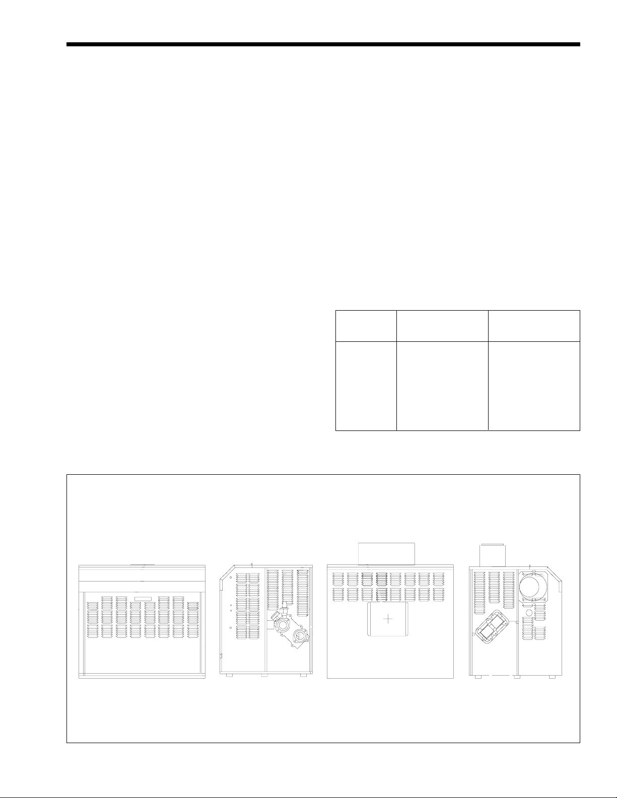
INDOOR OUTDOOR
Front Side
(Water Connections)
Figure 1. Mighty Max HH Boiler Configuration.
Rear Side
(Opposite Water
Connections)
Page 4
Page 4
LAARS HEATING SYSTEMS
SECTION 2.
Installation Instructions
2A. General Information
Install the Mighty Max HH boiler in accordance
with the procedures in this manual (or the Laars
warranty may be voided), local codes, and ordinances.
In the absence of such codes, install the heaters in
accordance with the latest edition of the National Fuel
Gas Code, ANSI Z223.1/National Fire Protection
Association (NFPA) 54. In Canada, the installation
must be in accordance with CAN1-B149.1 or .2 and
local codes. The authority having jurisdiction may
require the installation be in accordance with the
American Society of Mechanical Engineers (ASME)
Safety Codes for Controls and Safety Devices for
Automatically Fired Heaters, CSD-1, and in Canada,
Canadian Gas Association (CGA) 3.3. Any changes to
the boiler, its gas controls, gas orifices or wiring may
void the warranty. If field conditions require change,
consult the factory.
The Mighty Max HH boiler is designed-certified
for installation on a combustible floor. Do not install
the boiler directly on carpeting.
2B. Boiler Placement
2C. Installation of Outdoor Boilers
Caution
Outdoor installations are not recommended in
areas where the danger of snow blockage
exists.
1. Locate the boiler to provide at least the
minimum clearances as listed in Section 2B,
“Boiler Placement.” HH boilers require an
outdoor terminal kit when installed outdoors (see
Section 6, Parts List).
2. Do not locate the boiler in an enclosure or
through-wall recess. Avoid locations where wind
deflection off structures might cause down-draft.
When such wind conditions are possible, locate
the boiler at least 3 feet (.9m) from structures.
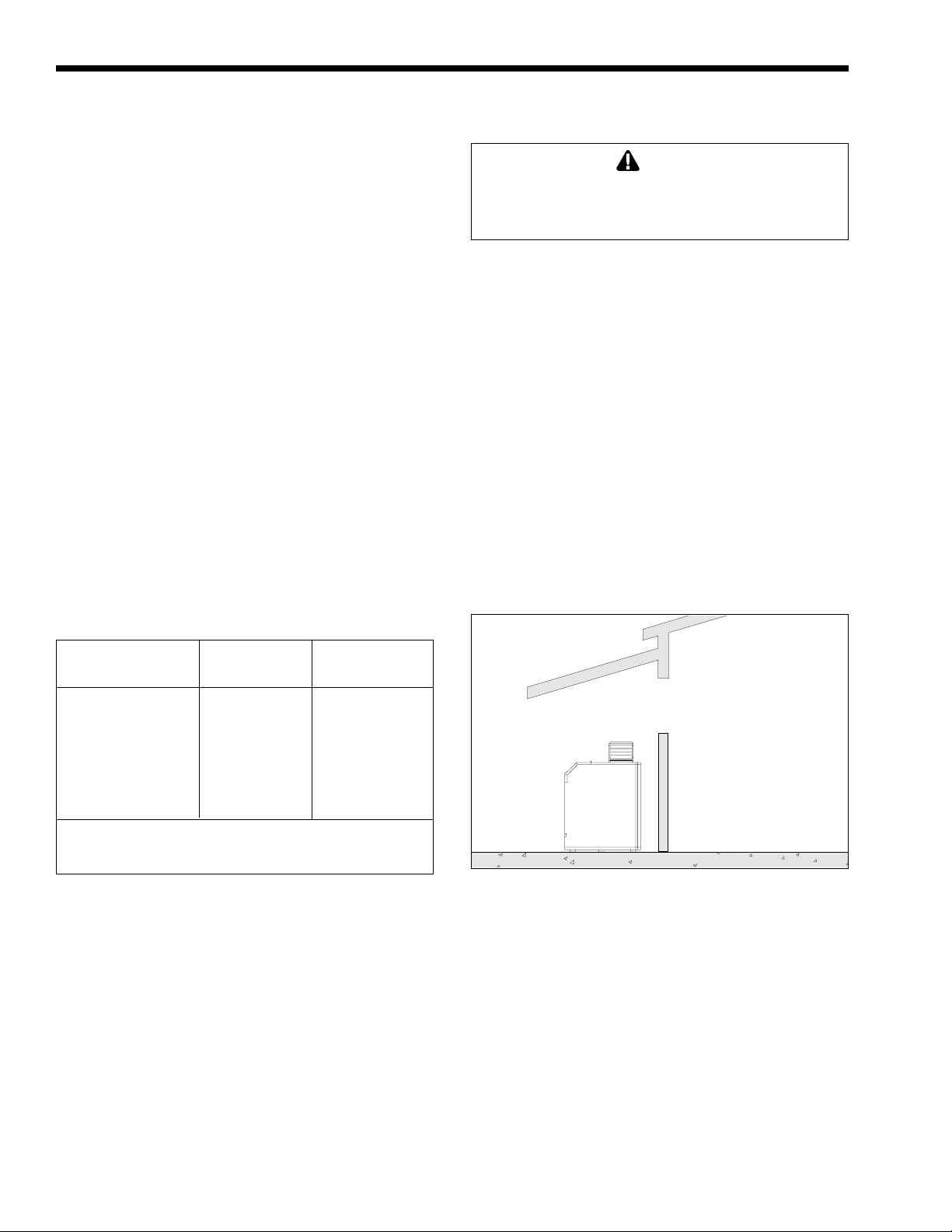
3. Never install the boiler under any kind of roof
overhang. Do not locate the boiler below or
adjacent to any doors, windows, louvers, grills,
etc. which communicate in any way with an
inhabited area of a building, even though such
communication might be through another
structure such as a garage or utility room (see
Figure 2).
Clearance From Indoor Outdoor
Combustibles Inches mm Inches mm
Top 18 457 Unobstructed
Water Conn. Side 12 305 12 305
Opposite Side 6 152 6 152
Front Alcove Unobstructed
Rear 6 152 6 152
Vent *6* 152 —
Flooring Combustible Combustible
Service clearance = 24 in. (610mm) at front of boiler.
*1 in. (25mm) if double wall vent is used.
Table 2. Minimum Boiler Clearances
from Combustible Surfaces.
Locate the boiler to provide adequate clearances
on all sides for maintenance and inspection. There
must also be minimum distances maintained from
combustible surfaces (See Table 2).
The boiler must be isolated or otherwise
protected from any source of corrosive chemical
fumes, such as trichlorethylene, perchlorethylene,
chlorine, etc. Install the boiler so that the gas ignition
system components are protected from water
(drippings, spraying, rain, etc.) during operation and
service.
WINDOW
OR GRILL
WRONG
Figure 2. Incorrect Installation of Boiler.
INDOOR
ROOM
2D. Freeze Protection
Boiler installations are not recommended in
areas where the danger of freezing exists unless
proper precautions are made for freeze protection.
Maintaining a mixture of 50% water and 50%
properly inhibited HVAC glycol is the preferred
method of freeze protection for hydronic systems. (Do
not use automotive antifreeze.) This mixture will
protect the boiler to temperatures of about -35°F
(-37°C). To get the desired temperature rise across the
boiler when this mixture is used, increase the water
flow recommendation by 15%. Increase the head loss
requirement by 20%. Note: If your application does
Page 5

Mighty Max Hydronic Boiler
Page 5
not require the full freeze protection of a 50%/50%
mixture, it is beneficial to use a maximum 30% glycol
solution. This mixture will protect the boiler to
temperatures of about 5°F (-15°C), and will serve as
burst protection for boilers that are not in use.
2E. Installation of Indoor Boilers
2E-1. Combustion Air Supply and
Ventilation
There are a variety of options available to the
installer when it comes to venting and combustion air;
venting can be vertical or horizontal, it can originate
at the top of the boiler or the back, and combustion air
can be obtained from the room where the boiler is
installed or ducted directly to the boiler from
outdoors. See Sections 2J through 2M for details.
2E-2. Removal of Existing Boiler
At the time of removal of an existing boiler, the
following steps shall be followed with each appliance
remaining connected to the common venting system
placed in operation, while the other appliances
remaining connected to the common venting system
are not in operation.
1. Seal any unused openings in the common
venting system.
2. Visually inspect the venting system for proper
size and horizontal pitch and determine there is
no blockage or restriction, leakage, corrosion
and other deficiencies which could cause an
unsafe condition.
3. Insofar as is practical, close all building doors
and windows, and all doors between the space in
which the appliances remaining connected to the
common venting system are located and other
spaces of the building. Turn on clothes dryers
and any appliance not connected to the common
venting system. Turn on any exhaust fans, such
as range hoods and bathroom exhausts so they
will operate at maximum speed. Do not operate a
summer exhaust fan. Close fireplace dampers.
4. Place in operation the appliance being inspected.
Follow the lighting instructions. Adjust
thermostat so appliance will operate
continuously.
5. Test for spillage at the draft hood relief opening
if the appliance is equipped with a drafthood,
after 5 minutes of main burner operation. Use
the flame of a match or candle, or smoke from a
cigarette, cigar or pipe.
6. After it has been determined that each appliance
remaining connected to the common venting
system properly vents when tested as outlined
above, return door, windows, exhaust fans,
fireplace dampers and any other gas-burning
appliances to their previous condition of use.
7. Any improper operation of the common venting
system should be corrected so the installation
conforms with the National Fuel Gas Code,
ANSI Z223.1. When resizing any portion of the
common venting system, the common venting
system should be resized to approach the
minimum size as determined using the
appropriate Tables in Appendix G in the
National Fuel Gas Code, ANSI Z223.1.
In Canada, at the time the boiler is removed from
common venting system, the common venting system
should be resized so the installation conforms to
CAN/CGA B149.1 or .2.
2E-2. Removal of Existing Boiler
Au moment du retrait d’une chaudière existante,
les mesures suivantes doivent être prises pour chaque
appareil toujours raccordé au système d’evacuation
commun et qui fonctionne alors que d’autres appareils
toujours raccordés au système d’évacuation ne
fonctionnent pas:
1. Sceller toutes les ouvertures non utilisées du
système d’évacuation.
2. Inspecter de façon visuelle le système
d’évacuation pour déterminer la grosseur et
l’inclinaison horiztonale qui conviennent et
s’assurer que le système est exempt
d’obstruction, d’étranglement, de fuite, de
corrosion et autres défaillances qui pourraient
présenter des risques.
3. Dans la mesure du possible, fermer toutes les
portes et les fenêtres du bâtiment et toutes les
portes entre l’espace, où les appareils tojours
raccordés et les autres espaces du bâtiment.
Mettre en marche les sécheuses, tous les
appareils non raccordés au système d’évacuation
commun et tous les ventilateurs d’extraction
comme les hottes de cuisinère et les ventilateurs
des salles de bain. S’assurer que ces ventilateurs
fonctionnent à la vitesse maximale, Ne pas faire
fonctionner les ventilateurs d’été. Fermer les
registres des cheminées.
4. Mettre l’appareil inspecté en marche. Suivre les
instructions d’allumage. Régler le thermostat de
façon continue.
5. Faire fonctionner le brûleur principal pendant 5
min ensuite déterminer si le coupe-tirage
déborde à l’ouverture de décharge. Utiliser la
flamme d’une allumette ou d’une chandelle ou la
afumée d’une cigarette, d’une cigare ou d’une
pipe.
6. Une fois qu’il a été déterminé, selon la méthode
indiquée ci-dessus, que chaque appareil raccordé
Page 6

Page 6
LAARS HEATING SYSTEMS
Distance from Gas Meter or Last Stage Regulator
0-100 feet 100-200 feet 200-300 feet
0-30m 30-60m 60-90m
Natural Propane Natural Propane Natural Propane
Size in.
320M
400M
520M
625M
775M
1000M
Notes: 1. These numbers are based on 1/2 inch (13mm) water column pressure drop.
1.25
1.25
1.50
1.50
2.00
2.00
2. Check supply pressure and local code requirements before proceeding with work.
3. Pipe fittings must be considered when determining gas pipe sizing.
mm
32
32
38
38
51
51
in.
1.25
1.25
1.25
1.25
1.50
1.50
Table 3. Natural Gas and Propane, Pipe Size Requirements.
au systéme d’évacuation est mis à l’air libre de
façon adéquate. Remettre les portes et les
fenêres, les ventilateurs, les registres de
cheminées et les appareils au gaz à leur position
originale.
7. Tout mauvais fonctionnement du systéme
d’évacuation commun devrait êvacuation
commun devrait être corrigé de façon que
l’installation soit conforme au National Fuel
Gas Code, ANSI Z223.1/NFPA 54 et (ou) aux
codes d’installation CAN/CGA-B149. Si la
grosseur d’une section du systéme devrait être
modifié ppour respecter les valeurs minimales
des tableaux pertinents de l’appendice F du
National Fuel Gas Code, ANSI Z223.1/NFPA 54
et (ou) des codes d’installation CAN/CGA-B149.
mm
32
32
32
32
38
38
in.
1.50
1.50
2.00
2.00
2.00
2.50
mm
38
38
51
51
51
64
in.
1.25
1.25
1.50
1.50
1.50
2.00
mm
32
32
38
38
38
51
operate at high altitudes have appropriate
stickers or tags attached.
3. The figures in Table 3 should be used to size the
gas piping from the gas meter to the boiler.
Check local codes for BTU/h capacity required.
4. Install a sediment trap (drip leg) ahead of the gas
controls (see Figure 4). Fit the trap with a
threaded cap which can be removed for cleaning.
5. When required by code, install a second manual
gas shutoff valve. Do not remove manual shutoff
valve supplied with the boiler.
6. Disconnect the boiler and its individual shutoff
valve from the gas supply piping system during
pressure testing of the system at pressures higher
than 1/2 psi (3.5 kPa). Isolate the boiler from the
gas supply piping system by closing its
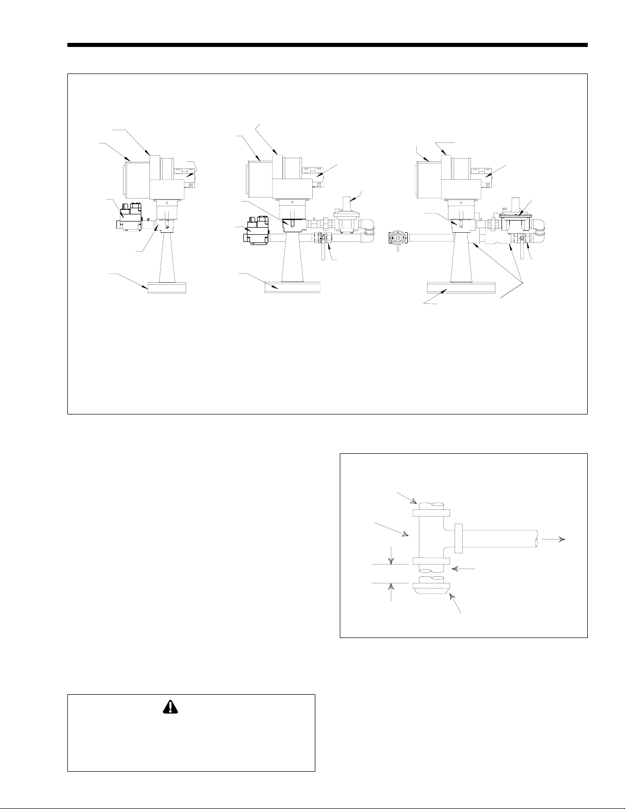
2F. Gas Supply and Piping
Review the following instructions before
continuing the installation.
1. Gas piping installation must be in accordance
with the latest edition of ANSI Z223.1/NFPA 54.
In Canada, the installation must be in accordance
with CAN1-B149.1 or .2 and all local codes that
apply. See Figure 3 for boiler gas valve
individual manual gas shutoff valve during any
pressure testing of the gas supply piping system
at test pressures equal to or less than 1/2 psi
(3.5 kPa).
7. Gas supply pressures to the boiler are listed in
Table 4.
Supply Pressure
Water Column
arrangement.
2. Check the rating plate to make sure the boiler is
Minimum 5
fitted for the type of gas being used. Laars
boilers are normally equipped to operate below a
2000 foot (610m) altitude. Boilers equipped to
Maximum 9
Table 4. Gas Supply Pressure Requirements.
in.
1.50
2.00
2.00
2.00
2.50
3.00
mm
38
51
51
51
64
76
Natural Gas Propane Gas
in.
mm
127
229
in.
1.50
1.50
1.50
2.00
2.00
2.50
in.
9
14
mm
38
38
38
51
51
64
mm
229
356
Page 7
Mighty Max Hydronic Boiler
Air Shutter
Enclosure
Filter
Housing
Automatic,
Regulator
and
Redundant
Gas Valve
Mixture
Plenum
Venturi
Blower
Motor
Filter
Housing
Venturi
Automatic
and
Redundant
Gas Valve
Mixture
Plenum
Air Shutter
Enclosure
Blower
Motor
Regulator
Manual Gas
Valves When
Used On
Canadian Unit
or U.S.Unit
Requiring
CSD-1 Code
Filter
Housing
Venturi
Air Shutter
Enclosure
Mixture
Plenum
Blower
Motor
Automatic
Main
Gas Valves
Page 7
Regulator
Manual Gas
Valves When
Used On
Canadian Unit
or U.S.Unit
Requiring
CSD-1 Code
SIZES:
320M, 400M
SIZES:
520M, 625M
SIZES:
775M, 1000M
Note: The above diagram is a representation. Actual venturi assembly may vary depending on boiler size.
Figure 3. Boiler Gas Valve Arrangement.
NOTE: The boiler and all other gas appliances
sharing the boiler gas supply line must be firing at
maximum capacity to properly measure the inlet
supply pressure. Low gas pressure could be an
Gas Supply
Inlet
indication of an undersize gas meter and/or obstructed
gas supply line.
8. Do not exceed the maximum inlet gas pressures
Tee
Fitting
specified. Excessive pressure will result in
damage to the heater's gas controls. The
minimum pressures specified are for gas input
3 In.
(76mm) Min.
Nipple
adjustment.
9. The correct differential gas pressure is stamped
on the rating plate. The regulator is preset at the
Cap
factory, but may need adjustment for altitude per
Section 3.
10. Before operating the heater, test the complete
Figure 4. T-Fitting Sediment Trap Installation.
gas supply system and all connections for leaks
using a soap solution.
To Equipment
Inlet
Caution
Since some leak test solutions (including soap
and water) may cause corrosion or stress
cracking, rinse the piping with water after
testing.
Page 8
Page 8
LAARS HEATING SYSTEMS
2G. Water System Requirements
2G-1. Flow Requirements
The Model HH boilers must have continuous
flow through the heat exchanger when firing for
proper operation. The system pump must be capable
of developing sufficient pressure to overcome the
resistance of the boiler plus the entire circulating
system at the designated flow (see Table 5). The
temperature rise across the boiler should never exceed
40°F (22°C).
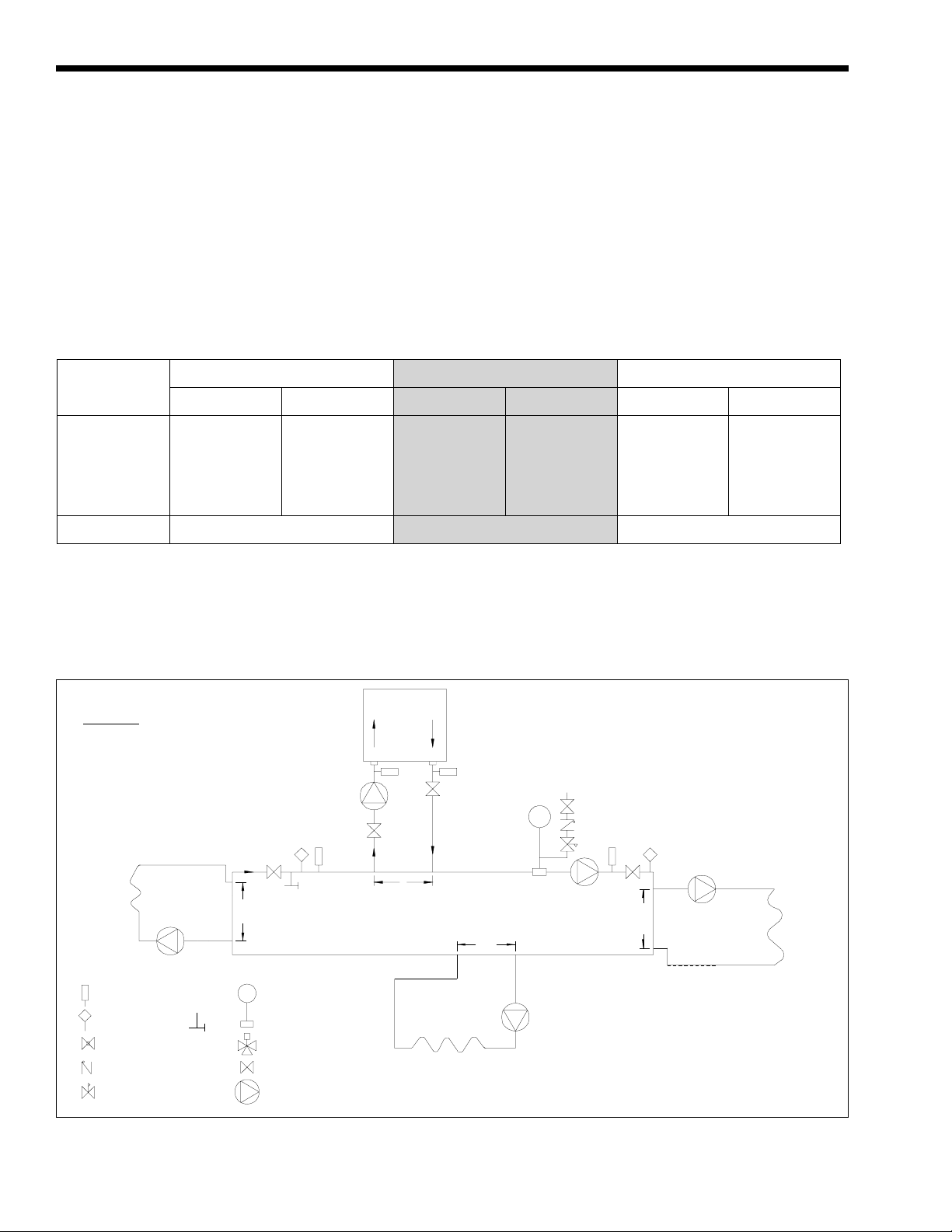
2G-2. Variable Water Flow Systems
There can be reduced water flow through the
boiler in heating systems using zone valves, zone
pumps or 3-way valves. This can result in a high
temperature rise across the boiler. Laars recommends
primary-secondary pumping for all variable flow
systems. The boiler pump in a primary-secondary
system maintains constant flow through the boiler
even though the system flow is variable. In a primarysecondary system the pressure drop of the boiler is not
added to the system (see Figure 5).
TEMPERA TURE RISE IN DEGREES (°F / °C )
10°F
6°C
15°F
MODEL
LPS H/L m
3.41
4.29
5.55
6.69
8.33
10.73
3.4
8.0
2.7
3.7
6.9
11.4
GPM H/L ft.
36
45
58
70
87
113
5.0
11.5
4.0
5.7
9.4
16.5
HH0320M
HH0400M
HH0520M
HH0625M
HH0775M
HH1000M
GPM H/L ft.
54
68
88
106
132
170
11.2
26.2
8.9
12.2
22.5
37.3
Flow High Normal Low
NOTES: Sizes 320M and 400M use 4-pass heat exchangers; 520M, 625M and 775M use 2-pass heat exchangers.
*Pressure drop (head loss) through the boiler, expressed in ft. of H2O.
Shaded area is the recommended flow and temperature rise. Minimum inlet temperature is 105°F.
8°C
LPS H/L m
2.27
2.84
3.66
4.42
5.49
7.13
1.5
3.5
1.2
1.7
2.9
5.0
20°F
GPM H/L ft.
27
34
44
53
65
85
2.8
6.6
2.6
3.3
5.2
9.4
11°C
LPS H/L m
1.70
2.15
2.78
3.34
4.10
5.36
0.9
2.0
0.8
1.0
1.6
2.9
WARNING: This drawing shows suggested
piping configuraiton and valving. Check with
local codes and ordinances for additional
requirements.
Boiler Circulation
12"
Max.
LEGEND:
Thermometer
Temperature
Sensor
Globe Valve
Check Valve
Pressure Reducing Valve
w/Fast Fill Bypass
Purge
Valve
Expansion T ank
with Air Scoop and
Auto Air Vent
3-Way Valve
Valve
Pump
Pump
Table 5. Temperature Rise.
12"
Max.
12"
Max.
Cold Water
Make-Up
System Pump
12"
Max.
Boiler circuit piping must be equal to or larger than
boiler water connection size.
Boiler circulation pump sized for flow through
boiler.
Dotted devices indicate alternate locations.
Figure 5. Primary-Secondary Plumbing.
Page 9
Mighty Max Hydronic Boiler
Page 9
2G-3. System Pressure Requirements
The Model HH boilers are designed to operate
on closed, pressurized systems. Maintain a minimum
of 12 psi (81.8 kPa) on the system where boiler supply
water temperature is 200°F (93°C) or less. If higher
temperatures are required, the minimum system
pressure should be at least 15 psi (102.2 kPa) above
the water vapor pressure corresponding to the elevated
water temperature.
The Model HH boilers are not suitable for open
systems unless the supply water temperatures are
kept below 180°F (82°C), and a minimum of 5 psi
(34.1 kPa) static head is maintained at the boiler.
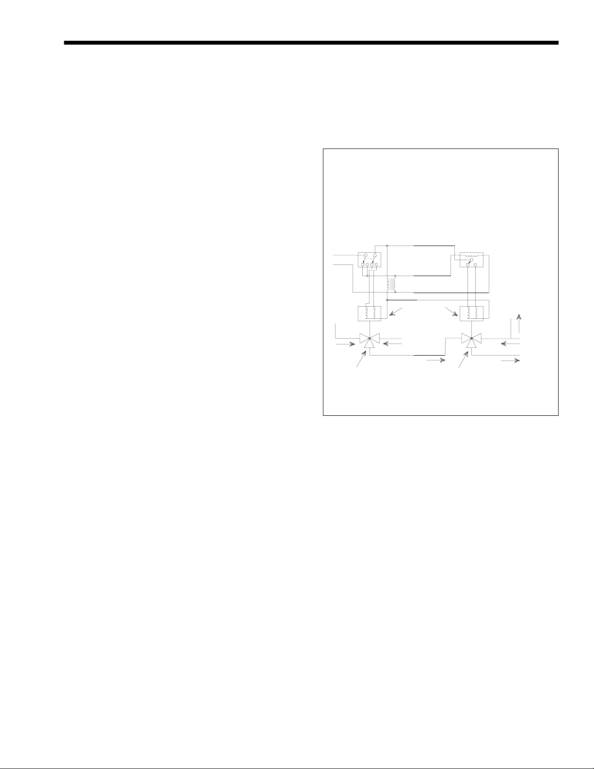
2G-4. Hot/Chilled Water Systems
When a boiler is connected to an air
conditioning system where the same water is used for
heating and cooling, you must prevent chilled water
from entering the boiler. When changing such a
system from cooling to heating, allow the chilled
water to circulate through the building, after the
chiller has been turned off, for a period long enough
for the water to warm up to at least 105°F (41°C)
before the water flows into the boiler. It is equally
important to prevent hot water from entering the
chiller. The system shown in Figure 6 is suggested to
make sure the system water is neither too hot nor too
cold when a changeover takes place. When a boiler is
connected to heating coils located in air handling units
(where they may be exposed to refrigerated air
circulation), install a flow control valve or other
automatic means to prevent gravity circulation of
chilled water through the boiler. Chilled water in the
boiler will create condensate on the boiler tubes.
Boilers installed in violation of the foregoing may
void the warranty.
2G-5. Combined Space Heating/Potable
Water Heating Systems
When using the Mighty Max boiler as a source
of heat for a combined space heating/potable water
heating system, be sure to follow the instructions of
the space heating system.
Do not use water piping, fittings, valves, pumps,
and any other components which are not compatible
with potable water.
Do not connect the heater, which will be used to
supply potable water, to any heating system or
components previously used with a nonpotable water
heating system.
Do not add boiler treatment or any chemicals to
the heating system piping, since the piping contains
water for potable use.
Do not use solder containing lead in the potable
water lines.
Some jurisdictions may require a backflow
preventer in the cold water line. In such cases,
pressure relief valve may discharge water due to
expansion. An expansion tank approved for potable
water will eliminate this condition. Follow the
manufacturer's instructions for installation of the
expansion tank.
Suggested Wiring Diagram For
Tempering System Water at
Changeover From Heating To Cooling
DPDT Manual or Automatic
Change-Over Switch
DPDT - Set at Change-Over
Temperature
115/24V
Transformer
From
Chiller
3-Way Valve No. 1
Change-Over
(Heating and Cooling)
Figure 6. Boiler-Chiller Installation.
Valve Motors
2-Pos
3-Wire - 24V
From
Boiler
3-Way Valve No. 2
To By-Pass
Both Heater and
Chiller
Clock Timer
Auto-Resetting
Set at 15 Minute SPDT
To Boiler
and
Chiller
By-Pass
From
System
To
System
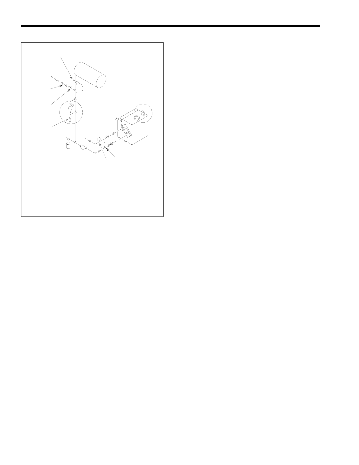
2H. Piping of System to Boiler
1. Be sure to provide gate valves at the inlet and
outlet to the boiler so it can be readily isolated
for service.
2. The pressure relief valve installed in the tapped
opening provided in the outlet header must be
piped, but not fastened, to a drain or floor sink.
The drain pipe must be the same size as the valve
outlet and must pitch downward from the valve. If
the PRV supplied with the boiler is not factory
installed, install it in the front header consistent
with the ANSI/ASME Boiler and Pressure Vessel
Code, Section IV. Pay special attention to relief
valve settings in installations where the boiler is
located on the ground floor of a tall building, or
where the operating temperature of the boiler is
above 210°F (99°C). In both instances, the static
pressure of the system is elevated and could cause
the relief valve to leak and bring considerable raw
water into the system. Where no special setting of
the relief valve is ordered, the factory will furnish
a 75 psi (511.5 kPa) setting. Never reduce the
relief valve opening. If necessary, install the relief
valve in a Tee immediately past the boiler outlet.
Page 10
Page 10
LAARS HEATING SYSTEMS
Air Changer
and Tank
Drainer
Make-Up
Water
Supply
Check
Valve
Pressure
Reducing
Valve
Blow Down
Valve
Strainer
NOTES: Select Method 1 or 2 when using low water cutoff accessory:
1. Under Method 1, the low water cutoff is furnished by Laars and shipped
as a separate item for fieldinstallation.
2. Under Method 2, electronic low water cutoff isinstalled, wired and tested
on boiler in Laars factory.
3. Preferred locaiton of system pump is shown. Compression tank must
always be on suction side of pump.
Figure 7. Boiler Piping.
To Drain
Method 1
To
System
Pump
Expansion
Tank
Method 2
To
Drain
Thermometer
Temperature
and Pressure
Gauge
3. Provide a boiler installed above radiation level
with a low water cutoff device either as part of
the boiler or at the time of boiler installation (see
Figure 7).
4. Install manual and/or automatic bleeding devices
at high points in the system to eliminate air.
Install a correctly sized expansion or
compression tank with suitable air charger and
tank drainer, as appropriate.
5. Support the weight of all water and gas piping by
suitable hangers or floor stands.
6. Check piping diagrams with local applicable
plumbing, heating and building safety codes.
2I. Filling The System
1. Ensure the system is fully connected. Close all
bleeding devices and open make-up water valve.
Allow system to fill slowly.
2. If make-up water pump is employed, adjust
pressure switch on pumping system to provide a
minimum of 12 psi (81.8 kPa) at the highest
point in the heating loop.
3. If a water pressure regulator is provided on the
make-up water line, adjust the pressure regulator
to provide at least 12 psi (81.8 kPa) at the
highest point in the heating loop.
4. Open bleeding devices on all radiation units at
the high points in the piping throughout the
system, unless automatic air bleeders are
provided at such points.
5. Run system circulating pump for a minimum of
30 minutes with the boiler shut off.
6. Open all strainers in the circulating system,
check flow switch operation, and check for
debris.
7. Recheck all air bleeders as described in Step 4
above.
8. Check liquid level in expansion tank. With the
system full of water and under normal operating
pressure, the level of water in the expansion tank
should not exceed 1/4 of the total, with the
balance filled with air.
9. Start up boiler according to procedure described
in Section 3A. Operate the entire system,
including the pump, boiler, and radiation units
for one (1) hour.
10. Recheck the water level in the expansion tank. If
the water level exceeds 1/4 of the volume of the
expansion tank, open the tank drainer and drain
to that level.
11. Shut down the entire system and vent all
radiation units and high points in the system
piping as described in Step 4 above.
12. Close make-up water valve and check strainer in
pressure reducing valve for sediment or debris
from the make-up water line. Reopen make-up
water valve.
13. Check gauge for correct water pressure and also
check water level in the system. If the height
indicated above the boiler insures that water is at
the highest point in the circulating loop, then the
system is ready for operation.
14. Within three (3) days of start-up, recheck all air
bleeders and the expansion tank as described in
Steps 4 and 8 above.
IMPORTANT:
The installer is responsible for identifying to the
owner/operator the location of all emergency
shutoff devices.
2J. Venting and Combustion Air
Information
Provisions for venting and supply of air for
venting and combustion must be done in accordance
with these instructions and applicable requirements of
the latest edition of ANSI Z223.1/NFPA 54. In
Canada, installation must be in accordance with CAN/
CGA B149.1 or .2, and applicable local codes.
There are a variety of ways to provide venting
and combustion air for the boiler (see Figure 8).
Page 11

Mighty Max Hydronic Boiler
Screen Provided
On Vertical Intake
Air Terminal
Category I
Vertical Venting (Category I)
Combustion Air In
Through Louvers
Page 11
For vertically ducted combustion air:
• Combustion air intake must
terminate at least 3 feet (0.91m)
lower than vent termination, if it is
located within a 10 foot (3.05m)
radius.
• Combustion air intake must be at
least 1 foot (0.3m) above roof top
and normal snow levels.
Vertical Venting
with Ducted
Combustion Air
Non-Category I
Horizontal Venting
Any Vent Which Does Not Meet
Category I Combustion Air
Through Louvers
Exhaust Terminal Detail
Wall
Side View
Horizontal
Intake Terminal Detail
(Combustion Air)
Horizontal Venting
Ducted Combustion Air
(Certified As Direct Vent)
NOTE:All views are shown
from rear of heater
Figure 8. Venting and Combustion Air Options.
Wall
Side View
Page 12

Page 12
LAARS HEATING SYSTEMS
Vent
Collar/Stack
Blank Plate
(Boiler
Jacket)
Adapter Plate
Top Panel
1. Removal of Blank Plate and Adapter
Plate From Boiler
Blank Plate On
Boiler Jacket
Top Panel
Blank Plate On
Flue Collector
3. Blank Plate Placement
Over Stack Top Opening
Blank Plate
(Flue
Collector)
2. Removal of Blank Plate From
Rear of Flue Collector
Figure 9. Top-To-Rear Vent Collar.
The Mighty Max HH boiler is certified as a true
direct vent unit when installed according to the
instructions for horizontal venting and ducted
combustion air. This can be done even if the runs are
vertical.
2K. Top-to-Rear Vent Collar Conversion
The Mighty Max HH boiler is shipped with the
vent collar on top of the heater. Follow this procedure
to convert it for rear connection (see Figure 9).
1. Remove the adapter plate from the top panel.
2. On the boiler jacket, remove the top panel and
ease its lip from under the edge of the bonnet to
gain access to the flue collector.
Vent
Collar/Stack
4. Connecting Vent Collar/Stack
to Flue Collector
3. Remove the vent collar/stack from the flue
collector. Do not damage the vent collar/stack
during removal.
4. Remove the blank plate from the rear of the
jacket.
5. Remove the blank plate from the rear section of
the flue collector. Be careful not to lose the
insulation attached to the plate.
6. Apply high temperature sealant and install the
blank plate (previously removed from the rear
section of the flue collector) on top of the flue
collector.
7. Install the blank plate (previously removed from
the rear of the boiler jacket) over the stack
opening on the top panel of the boiler.
Page 13

Mighty Max Hydronic Boiler
r
Page 13
8. Apply high temperature sealant (see Table 6) to
vent collar/stack and install on the rear of the
flue collector.
Term Description
Pipe Type 304, Type 316, or 29-4C
stainless steel, 24 gauge minimum
Joint Sealing 3M Type 433 sealing tape with 400°F
(204°C) rating or high temperature
silicone sealer with 500°F (260°C)
rating, Dow No. 736
Insulation R5 minimum with protective cover
Table 6. Required Horizontal Venting Material.
9. Slip the adapter plate over the vent collar/stack
and install it onto the rear boiler jacket (see
Figure 9).
2L. Venting
Venting must be in accordance with these
instructions and applicable requirements of the latest
edition of ANSI Z223.1/NFPA 54. In Canada,
installation must be in accordance with the latest
edition of CAN/CGA B149.1 or .2, and applicable
local codes.
2L-1. Vertical Venting - Category I
The Mighty Max boiler has a fan-assisted
combustion system, so vertical vents must be installed
in accordance with the special code requirements for
Category I - Fan-Assisted Appliances. These
requirements can be found in the latest edition of
ANSI Z223.1/NFPA 54, Appendix G, Table 1, and in
Canada, CAN/CGA B149.1 or .2, Amendment No. 1.
These codes permit installation as a single appliance
or in combination with other Category I appliances.
However, there are very important requirements for
minimum and maximum vent diameter and length.
Make sure vertically-vented installations comply with
these codes.
NOTE: If a vent cannot be installed in
accordance with the requirements of these codes, it
must be installed as a horizontal vent, even if it is
mainly vertical.
2L-2. Vertical Venting - Non-Category I
When venting does not meet the code
requirements for Category I - Fan-Assisted Vertical
Vents, it can develop positive pressure. Such venting
must be installed in accordance with this section or
Section 2L-3.
The following requirements must be used for
Non-Category I venting:
1. Laars specified vent pipe material (Table 6) and
sizes (Table 7).
2. Pipe insulation and sealing tape.
3. Routing vent pipe through spaces which, except
for the terminal, remain above 60°F (16°C)
during heater operation.
2L-3. Horizontal Venting - Non-Category I
When venting is horizontal, or cannot meet the
code requirements for Category I - Fan-Assisted
Vertical Vents, it can develop positive pressure and
must be installed in accordance with this section.
The following requirements must be used for
Horizontal Venting - Non-Category I:
1. Laars specified vent pipe material (Table 6) and
sizes (Table 7).
2. Laars side wall vent hood.
3. Pipe insulation and sealing tape.
4. Routing vent pipe through spaces which, except
for the terminal, remain above 60°F (16°C)
during heater operation.
Heater
Size
320M
400M
520M
625M
775M
1000M
IMPORTANT: Maximum pipe length allowed is 50 feet (15m), regardless of the number of elbows. Maximum number of elbows allowed is 5.
Vent pipe minimum clearance from combustible surfaces is 6 inches (152mm).
Pipe Diameter M ax Pipe Length
in.
6
7
8
8
9
10
mm
152
178
203
203
229
254
Table 7. Vent Piping Specifications (Combustion Air Exhaust).
ft.
50
50
50
50
50
50
m
15
15
15
15
15
15
Max No.
of Elbows
5
5
5
5
5
5
Side Wall
Vent Terminal
Part Number
D2004500
D2004600
D2004700
D2004700
D2004800
D2006200
Side Wall
Combustion Air
Terminal Part Numbe
20260701
20260702
20260703
20260704
20260705
20526906
Page 14

Page 14
LAARS HEATING SYSTEMS
Vent Hood
3 (0.9m) Minimum
Vent
Hood
Vent Hood
7 (2.1) Minimum
Above Public
Walkway
Figure 10. Building Exterior.
6 (1.8) Above Any
Outside Air Intake
Within 10 (3.0)
Vent Hood
Vent Hood
1 (0.3) Above Grade
2L-4. Side Wall Vent Terminal
The side wall vent hood must be used when the
heater is vented through a side wall. It provides a
means of installing vent piping through the building
wall, and must be located in accordance with ANSI
Z223.1/NFPA 54 and applicable local codes. In
Canada the installation must be in accordance with
CAN/CGA B149.1 or .2 and local applicable codes
(see Figure 10). Consider the following when
installing the terminal:
1. Locate the vent terminal so that it will not be
damaged by pedestrians and other traffic, and so
the discharge is not objectionable. The National
Fuel Gas Code requires a through-wall vent
terminal be at least 7 feet (2.1m) above grade if
located at a public walkway.
2. Locate the vent terminal so that vent gases
cannot be drawn into air conditioning system
inlets. The National Fuel Gas Code requires that
it be at least 6 feet (1.8m) above any such inlet
that is within 10 feet (3.0m).
3. Locate the vent terminal so that vent gases
cannot enter the building through doors,
windows, gravity inlets or other openings. The
National Fuel Gas Code requires that it be
located at least 4 feet (1.2m) below, 4 feet
4 (1.2)
Minimum
Vent Hood Must Be
Mounted 4 (1.2)
Minimum Below Windows
Dimensions shown in feet (m).
(1.2m) horizontally from, or 3 feet (0.9m) above
such openings.
4. Locate the vent terminal so that it cannot be
blocked by snow. The National Fuel Gas code
requires that it be at least 12 inches (305mm)
above grade, but the installer may determine it
should be higher depending on local conditions.
5. Locate the terminal so the vent exhaust does not
settle on building surfaces and other nearby
objects. Vent products may damage such
surfaces or objects. But the actual construction
of the vent terminal and the flow of vent
products must not be altered.
6. Locate the terminal at least 6 feet (1.8m)
horizontally from any gas or electric metering,
regulating, or relief equipment, or building
opening.
2M. Air for Combustion and Ventilation
The boiler requires air for combustion and the
space around the boiler requires ventilation.
Combustion air can be provided by standard practices
as specified in the installation codes (ANSI Z223.1/
NFPA 54, in Canada, CAN/CGA B149.1 or .2 and
local applicable codes), or ducted directly to the
boiler. Ventilation air must be provided in either case.
4 (1.2)
Minimum
Page 15

Mighty Max Hydronic Boiler
Page 15
2M-1. Air From Room
Standard requirements for providing air for
combustion and ventilation are provided by ANSI
Z223.1/NFPA 54 and in Canada by CAN/CGA
B149.1 or .2. These codes require passages be
provided for air flow into the space where the boiler is
installed. The size of these passages is based on the
firing rate of the boiler and the path of air flow into
the space. In general, installations which take air from
inside the building require larger passages than those
which take air directly through an outside wall.
Failure to provide adequate combustion and
ventilation air can cause the boiler, and other
appliances occupying the same space, to operate with
dangerous and inefficient combustion, and can cause
overheating of the space. Be sure to provide air
passages in accordance with ANSI Z223.1/NFPA 54,
in Canada, CAN/CGA B149.1 or .2 and local
applicable codes, and do not permit any other
condition, such as an exhaust blower, to affect the air
supply for combustion and ventilation.
2M-2.Ducted Combustion Air
Combustion air can be brought directly to the
boiler through a duct of suitable size and length (see
Table 7). Consult Laars about installations not
covered by Table 7.
Combustion air must be taken from out-of-doors
by means of the Laars side wall terminal.
Locate the terminal within 10 feet (3.0m) of the boiler
vent exhaust terminal, but no closer than 3 feet (0.9m)
(centerline distance).
Do not locate the air inlet terminal near a source
of corrosive chemical fumes (e.g., cleaning fluid,
chlorine compounds, etc.). Locate it so that it will not
be subject to damage by accident or vandalism. It
must be at least 7 feet (2.1m) above a public walkway.
Use single-wall galvanized pipe for the
combustion air duct. Route the duct to the heater as
directly as possible. Seal all joints with tape. Provide
adequate hangers. The heater must not support the
weight of the combustion air duct.
When combustion air is ducted to the boiler,
other provisions must be made for boiler room
ventilation. HH boilers lose less than 1 percent of
their input rating to the room, but other heat sources
may be present. Provide enough ventilation air to meet
comfort specifications. Make sure the ventilation air is
not directed at the boiler, water piping or other
equipment which could be damaged by freezing.
Boiler Size Assembly Number
320 20258101
400 20258102
520 20258103
625 20258104
775 20258105
1000 20258106
Table 8. Combustion Air Assembly.
Louvered
Plate
Inlet
Adapter
Plate
Pipe
2M-3.Conversion for Ducted
Combustion Air
The conversion to ducted combustion air
requires the parts listed in Table 8. Follow these
procedures to convert the heater (see Figure 11):
Ducted Combustion
Air Pipe
Figure 11. Ducted Combustion Air Conversion.
Page 16

Page 16
LAARS HEATING SYSTEMS
1. Remove the louvered plate from the left side of
the boiler.
2. Remove the adapter plate from the shipping
container.
3. Install the blower motor housing collar in gasket.
4. Slip one end of the inlet pipe over the collar on
the adapter plate.
5. Slide the inlet pipe and adapter plate into the
boiler opening until the pipe is aligned with the
blower motor.
6. Slip the end of the inlet pipe over the blower
motor housing collar.
7. Secure the adapter plate to the side of the boiler
with the 4 screws.
2M-4.Combustion Air Piping
Run piping of the appropriate size between the
air intake terminal and the boiler (see Table 7). Table
9 lists the materials for piping the boiler.
Term Description
Pipe Single-wall galvanized steel pipe,
24 gauge minimum.
Joint Sealing Permanent duct tape or aluminum
tape
Insulation Not required, but recommend R5
insulation for cold installations
(consult American Society of
Heating, Refrigerating, and
Air Condditioning Engineers
(ASHRAE) handbook
Table 9. Required Combustion Air Piping Material.
2N. Electrical Wiring
WARNING
Electrically ground the heater in accordance
with the latest edition of ANSI/NFPA 70. In
Canada, use CSA C22.1. Do not rely on the
gas or water piping to ground the metal parts
of the heater. Often, plastic pipe or dielectric
unions isolate the boiler electrically. Service
and maintenance personnel who work on or
around the boiler may be standing on wet
floors and could be electrocuted by an
ungrounded boiler.
1. Check boiler wiring and pump for correct
voltage, frequency, and phase.
2. Wire the boiler and pump exactly as shown in
the wiring diagram supplied with the boiler (see
Figure 12).
3. Electrically interlock the pump and boiler so the
boiler cannot come on unless the pump is
running.
4. Connect all field-installed devices (relays,
timers, temperature devices, etc.) to the boiler
wiring at points labeled “Field Interlock” (see
Figure 12).
SECTION 3.
Operation
WARNING
Do not use this appliance if any part has been
under water. Immediately call a qualified
service technician to replace the appliance.
3A. Start Up Requirements
Lighting: Safe lighting and other performance
criteria were met with the gas manifold and control
assembly provided on the boiler when it underwent
tests specified in ANSI Z21.13 Standard.
Before placing the boiler in operation, check the
automatic safety shutoff devices. Once the boiler is
connected to the gas piping and after all of the
requirements in Section 2 have been met, follow this
procedure:
1. Before beginning the tests, make sure the main
manual gas valve, and any other boiler firing
valves, are in the OFF position.
NOTE: The gas valve is turned off as follows:
• Size 775/1000 Valve is OFF when handle is at
right angle to gas pipe.
• Sizes 520/625 Turn clockwise to OFF and
• Sizes 320/400 Press in gas control knob
slightly and turn clockwise to
OFF. Knob cannot be turned
unless it is pushed in slightly.
Do not force it.
2. Make sure the power switch on the boiler is in
the ON position. Reset all safety devices (high
limit, pressure switch, Low-Water-Cutoff, etc.).
3. Normal Operating Sequence
When the circulation pump is running, the boiler
will turn itself on and off in response to the
water temperature. When the water cools below
the set temperature, the following sequence
occurs:
a. The aquastat powers the ignition control.
b. The ignition control turns on the
combustion fan. After about a 15 second
Page 17

Mighty Max Hydronic Boiler
Page 17
ATTENTION
IGNITION SYSTEM 20 ON/OFF
SIZES 320-1000, NA TURAL OR PROPANE
Au moment de l’entretien des commandes, étiquetez tous les fils
avant de les débrancher. Les erreurs de câblage peuvent nuire au
bon fonctionnement et être dangereuses.
S’assurer que l’appareil fonctionne adéquatement une fois
l’entretien terminé.
Caution
Figure 12. Wiring Diagram.
Label all wires prior to disconnection when servicing controls.
wiring errors can cause improper and dangerous operation.
Verify proper operation after operation servicing.
Page 18

Page 18
LAARS HEATING SYSTEMS
Front View of Boiler
Igniter
Junction
Box
NOTE: Sight glass
location may vary.
Figure 13. Periodic Flame Observation.
Sight Glass
For Flame Observation
pre-ignition purge, while the fan clears the
combustion chamber, the igniter is turned
on. The igniter takes about 25 seconds to
heat up. You can see a glow through the
view port (see Figure 13).
NOTE: The manual gas valve must be ON for the
burner to ignite. This valve is turned ON as follows:
• Size 775/1000 Valve is ON when handle is
parallel to as pipe.
• Sizes 320/400 Turn counterclockwise 520/625
to ON.
c. When the igniter is hot, the ignition control
turns on the gas valve and the burner
ignites. You can see the burner flame
through the view port (see Figure 13).
d. The boiler operates until the aquastat
senses that the water is hot enough, and the
burner shuts off. The combustion fan runs
for about one minute to blow all
combustion products out of the boiler.
If the igniter fails to ignite the burner in step 3
(for example, if there is air in the gas line), the
ignition control shuts off the gas valve after a few
seconds of operation. The purge and ignition sequence
is automatically repeated. If there is no ignition in
three tries, the ignition control “locks out” until the
problem is corrected. Contact a qualified service
technician.
3B. Hi-Limit Checkout
After running the boiler for a long enough period
to bring the water temperature within the range of the
hi-limit, slowly back off the high limit setting until the
boiler shuts off. The main burners should re-ignite
when the hi-limit is turned back up to its original
setting and the hi-limit is reset.
3C. Venturi and Gas Pressure Regulator
System
3C-1. Overall Operation
The gas control system of the Mighty Max boiler
is similar to that of a carburetor of a gasoline engine: a
venturi pulls the gas into the combustion air stream
(see Figure 14). In this system, changes in combustion
air flow automatically change the gas flow.
Air
Gas
Orifice
Air/Gas
Mixture
Figure 14. Typical Venturi System.
The flow of air through the venturi creates a
pressure difference. At the narrowest point of the
venturi, the throat, high velocity creates a low
pressure condition which pulls gas in through an
orifice.
For a correct gas/air ratio, the gas pressure must
be the same as the air pressure, but with a slight
negative offset. A special gas regulator (called a
“negative pressure regulator”) which has an equalizer
tube connected to the venturi inlet, maintains the
required gas pressure.
When the system is operating, a combustion fan
forces air into the venturi, creating pressure at the
inlet. The gas regulator sets gas pressure, and gas is
pulled through the orifice. The sizes of the venturi
throat and gas orifice are factory set to provide the
correct air/gas ratio.
3C-2. Venturi Adjustment
The field checkout involves measuring gas and
venturi pressures, and observing the flame through the
sight glass. If necessary, the gas input rate can be
measured by timing the gas meter.
Equalizer
Tube
Negative
Pressure Regulator
Gas
Overall
Operation
Page 19

Mighty Max Hydronic Boiler
Page 19
Use a single, inclined manometer or digital
manometer with a 4.0 inch water column range. Install
shutoff valves at the gas orifice (regulator outlet) tap
(red), at the venturi inlet tap (blue) and at the venturi
throat tap (yellow). After installing the shutoff valves,
be certain they are closed.
1. With the heater off, connect the positive side of
the manometer to the shutoff valve on the
venturi inlet tap (blue). Open the shutoff valve.
2. Loosen the nut on the blower damper to allow
for adjustment. Turn the boiler on so that the
blower is running and the boiler is not firing. In
this unfired condition, adjust the damper until
the venturi inlet pressure (blue tap) is 1.2 inches
water column.
3. Approximately 40 seconds after the blower starts
the gas valves will open. The boiler is now
firing. If the heater is not running, check all
manual gas valves and heater safety devices.
Ensure proper gas supply pressures according to
the table in Section 2.
4. Now that the boiler is firing, use the blower
damper to readjust the venturi inlet pressure
according to the installation’s altitude in Table
10 (+1.6" w.c. at sea level).
6. Using the toggle switch, turn the heater off. Turn
the heater back on and check the gas pressure
offset after the heater has fired. If the gas offset
pressure is not according to Table 10, adjust the
regulator as needed.
7. While the heater is still running, close the
shutoff valve on the gas orifice tap (red), then
remove the manometer hose from the shutoff
valve. Connect the negative side of the
manometer to the shutoff valve on the venturi
throat tap (yellow). This reading is called the
venturi throat differential pressure and should
appear according to altitude in Table 10 (+2.6"
w.c. at sea level). If it does not appear according
to Table 10, contact a qualified service
technician.
Venturi Inlet
“Low” Side of
Manometer
“High” Side of
Manometer
Tap (Blue)
Elevation Venturi Inlet Gas Throat
Ft. Pressure Pressure Differential
(Blue Tap) Offset Pressure
“WC H20” “WC H20” “WC H20”
SEA LEVEL +1.6 +0.4 +2.6
1000 +1.5 +0.4 +2.5
2000 +1.5 +0.4 +2.4
3000 +1.4 +0.4 +2.3
4000 +1.4 +0.3 +2.2
5000 +1.3 +0.3 +2.2
6000 +1.3 +0.3 +2.1
7000 +1.2 +0.3 +2.0
8000 +1.2 +0.3 +1.9
9000 +1.1 +0.3 +1.9
10000 +1.1 +0.3 +1.8
Table 10. Venturi Pressure Settings.
5. Leaving the positive side of the manometer
connected to the venturi inlet tap (blue), connect
the negative side of the manometer to the shutoff
valve on the gas orifice tap (red). Open the
shutoff valve to take a pressure reading. This
reading is called the gas pressure offset. Using
the regulator only, adjust the gas pressure offset
according to the installation's altitude in Table 5
(+0.4" w.c. at sea level). REPLACE THE
REGULATOR CAP BEFORE TAKING GAS
PRESSURE READINGS. Turn the regulator
screw clockwise to decrease the gas pressure
offset, turn the regulator screw counterclockwise to increase the offset.
Venturi Throat
Tap (Yellow)
Gas Orifice
Tap (Red)
Figure 15. Measurement of Venturi Throat Pressure
Differential.
After setting all pressures, turn the heater off and
replace each shutoff valve with the factory installed
threaded plugs. The venturi has now been adjusted for
proper operation.
3D. To Start Up System
(See Section 3A for Startup Requirements)
1. Be certain the system pump is running.
2. Set the thermostat or aquastat to its lowest
setting.
3. Turn off electric power to the appliance.
4. Remove the control access panel.
5. Turn off the manual gas valve.
6. Wait five (5) minutes to clear out any gas, then
smell for gas, including near the floor. Be sure to
smell next to the floor because some gas is
heavier than air and will settle on the floor.
Page 20

Page 20
Caution
This appliance is equipped with an ignition
device which automatically lights the burner.
Do not try to light the burner by hand.
WHAT TO DO IF YOU SMELL GAS
• Do not try to light any appliance.
• Do not touch any electric switch; do not use any
phone in your building.
• Immediately call your gas supplier from a
neighbor's phone. Follow the gas supplier's
instructions.
If you don't smell gas, go to the next step.
7. Turn on manual gas valves.
8. Rest all safety devices (manual resets on high
limit, low water cutoff, etc.).
9. Replace control access panel.
10. Turn on all electric power to the boiler.
11. Set thermostat to desired setting.
12. If the boiler will not operate, follow the
instructions to turn off gas to boiler and call your
service technician or gas supplier.
a. Turn off main electrical switch.
b. Close all manual gas valves.
3D-1. Setting Temperature Controls
The temperature control differential is factory
set at 15°F. This setting can be adjusted from 1 to
30°F to suit your application. Adjustment is made by
taking the cover off the temperature controller and
turning the potentiometer marked “DIFF”, which is
located just below and to the left of the controller’s
setpoint dial.
To set the temperature and high-limit controls:
a. Set the temperature controller at the system
design temperature.
b. For boilers with the temperature controller bulb
at the boiler inlet, set the high-limit 40°F to 50°F
above temperature controller setting.
c. For boilers with the temperature controller bulb
at the boiler outlet, set the high-limit 15°F to
25°F above temperature controller setting.
3E. To Shut Down System
To shut down the boiler, turn off all manual gas
valves and electrical disconnect switch.
NOTE: There is a filter which needs to be cleaned
prior to setting pressures. See Section 4D-2 “Filter
Service” before proceeding.
3F. Venturi Combustion Flow System
Verifying proper operation of the combustion
flow system has two aspects - air flow and gas flow.
Air flow is checked by measuring pressures at service
LAARS HEATING SYSTEMS
taps on the venturi. Gas flow is checked by evaluating
venturi pressures and the regulator offset pressure.
In a venturi flow system the difference between
various pressures is far more important than their
“gauge” value relative to the room. The gas pressure
offset and the gas orifice pressure differential are
especially important concepts. The following section
describes this setup procedure.
3F-1. Pressure Measurement Ports
Air flow enters the venturi through the filter box
and blower assembly. It is pushed through a
converging section and into the throat, where pressure
is reduced substantially. Gas flow is pulled into the
throat through an orifice. The orifice is located
between the throat and the regulator. Air and gas are
combined in the throat and mix thoroughly as they
proceed through the venturi tailpipe to the burner.
Service taps are provided at three places. One is
located on the chamber with the gas connection, this
tap is called the gas plenum tap. The other is located
above the gas plenum tap, this port is called the
venturi inlet tap. The third tap, gas orifice tap, is
located on the red orifice holder directly before the
gas connects to the venturi. These taps have service
plugs in them. Do not remove any of the plastic
fittings or plastic tubing. To evaluate system operation
requires accurate measurement at these taps. An
inclined manometer with a zero to 6 inches water
column range is ideal. Other instruments may be used,
but the “positive/negative” nature of the readings must
be well understood. Gas pressure offset measurements
are at very low levels (0.4" WC), the instrumentation
must be capable of determining it accurately.
3F-2. Venturi Adjustment
Note that an equalizer tube is connected from a
port on the side of the venturi inlet to the port of the
regulator. This is a very important component which
allows the regulator to track air pressure even when
abnormal conditions occur, such as blockage of the
combustion air. Before firing, confirm that this tube
and the venturi pressure switch tubes are in place and
firmly connected.
The field checkout involves measuring gas and
venturi pressures, and observing the flame through the
sight glass. If necessary, the gas input rate can be
measured by timing the gas meter.
Install shutoff valves at the gas orifice (regulator
outlet) tap (red), at the venturi inlet tap and at the gas
plenum tap. Do not remove any of the plastic fittings
or plastic tubing. After installing the shutoff valves,
be certain they are closed.
a. Unfired Venturi Differential Pressure
NOTE: Turn off the main manual gas valve.
Page 21

Mighty Max Hydronic Boiler
The difference in pressure between the venturi
inlet tap and the gas plenum tap (see Figure 16). This
measurement is taken by connecting the positive side
of the manometer to the venturi inlet tap and
connecting the negative side of the manometer to the
gas plenum tap. This measurement is taken with the
boiler not firing. It is a temporary setting used to start
the boiler and check for air flow problems.
Page 21
Figure 16. Unfired Venturi Differential Pressure.
b. Gas Offset Pressure
The difference in pressure between the venturi
inlet tap and the outlet of the gas regulator (see
Figure 17). This measurement is taken by connecting
the positive side of the manometer to the venturi inlet
tap and connecting the negative side of the manometer
to the gas orifice tap. This measurement is an
indication of the gas to air ratio and must be
performed while the unit is firing.
c. Gas Orifice Differential Pressure
This measurement is the pressure drop across the
gas orifice. This measurement is taken by connecting
the positive side of the manometer to the gas orifice
tap and the negative side of the manometer to the gas
plenum tap (see Figure 18). This measurement in
conjunction with the gas orifice size is an indication
of the gas firing rate and must be performed while the
unit is firing.
Figure 17. Gas Offset Pressure.
Figure 18. Gas Orifice Differential Pressure.
Page 22

Page 22
LAARS HEATING SYSTEMS
By setting the gas offset pressure and gas orifice
differential pressure according to Table 11, the correct
input rate and gas to air ratio is achieved.
GAS GAS ORIFICE UNFIRED
ELEVATION, OFFSET DIFFERENTIAL VENTURI
FT PRESSURE PRESSURE DIFFERENTIAL
inch W.C. inch W.C. inch W.C.
SEA LEVEL +0.4 +4.0 +5.8
2000 +0.4 +3.7 +5.3
4000 +0.4 +3.4 +4.9
6000 +0.4 +3.2 +4.6
8000 +0.4 +2.9 +4.2
10000 +0.4 +2.7 +3.9
Table 11. Venturi Pressure Settings.
3F-3. Venturi Setup Procedure
1. Loosen the nut on the blower shutter to allow for
adjustment. Turn the heater on so that the blower
is running and the heater is not firing. Measure
the unfired venturi differential pressure. In this
unfired condition, adjust the shutter until the
unfired venturi differential pressure is according
to Table 1, “Unfired Venturi Differential” (5.8 ±
.3 inches wc at sea level). If this pressure range
can not be achieved, check for blockage in the
combustion air inlet, boiler and venting system.
If there is no obvious cause contact a qualified
Laars service technician.
2. Approximately 40 seconds after the blower starts
the gas valves will open. The heater is now
firing. If the heater is not running, check all
manual gas valves and heater safety devices.
Ensure proper gas supply pressures according to
Table 4 in Section 2.
3. Measure the gas offset pressure. Using the
regulator only, adjust the gas offset pressure
according to the installation’s altitude in Table
11 (+0.4 inches wc. at sea level). REPLACE
THE REGULATOR CAP BEFORE TAKING
GAS PRESSURE READINGS. Turn the
regulator screw clockwise to decrease the gas
offset pressure, turn the regulator screw
counterclockwise to increase the offset.
4. Using the toggle switch, turn the heater off. Turn
the heater back on and check the gas offset
pressure while the heater is firing. If the gas
offset pressure is not according to Table 11,
adjust the regulator as needed.
5. Measure the gas orifice differential pressure.
This pressure must be adjusted according to
Table 1 (4.0 ± .2 inches wc at sea level). Use the
blower shutter to adjust the gas orifice
differential.
6. By adjusting the gas orifice differential, the gas
offset pressure will change. Therefore you must
repeat steps 3-5 until the gas offset and gas
orifice differential pressures are according to
Table 11.
7. After setting all pressures, turn the heater off and
replace each shutoff valve with the factory
installed threaded plugs. The venturi has now
been adjusted for proper operation.
SECTION 4.
Maintenance
4A. General Instructions
1. Oil the water circulating pump in accordance
with the manufacturer's instructions.
2. Oil the blower motor bearings every 6 months.
3. If a strainer is used in a pressure reducing valve
or in the piping, clean it every 6 months in
accordance with the manufacturer's instructions.
4. At startup and every 6 months after, look at the
main burner flame for proper performance. The
burner should not require maintenance in normal
operation. If any malfunction indicates that the
burner needs service (e.g., a flame that is yellow,
or entire burner surface glowing red), call a
professional service technician. Flame
characteristics may be inspected during the first
30 seconds after ignition. Characteristics of a
good flame are:
a. Blue flame color.
b. Dark-colored burner surface with
occasional glowing fibers on surface.
NOTE: After 30 seconds of operation the
combustion chamber will heat up and prevent reliable
flame observation.
5. Inspect the venting system for blockage, leakage,
and corrosion at least once a year.
6. Keep the heater area clear of combustible
material, gasoline, and other flammable liquids
and vapors.
7. Be sure all combustion air and ventilation
openings are not blocked.
8. After installation and first startup, check the heat
exchanger for black carbon soot buildup after the
following periods of operation: 24 hours, 7 days,
30 days, 90 days, and once every 6 months
thereafter.
4B. Heat Exchanger
Black carbon soot buildup on the external
surfaces of the heat exchanger is caused by one or
more of the following: incomplete combustion,
combustion air problems, venting problems and heater
short cycling. As soon as any buildup is seen, correct
the cause of the buildup. Scale can build up on the
Page 23

Mighty Max Hydronic Boiler
Page 23
inner surface of the heat exchanger tubes and
restrict the water flow. Inspect the heat exchanger in
accordance with Section 4B-1.
If the heat exchanger needs cleaning, see
Section 4B-2.
4B-1. Inspection of the Heat Exchanger
WARNING
Improper installation or maintenance can
cause nausea or asphyxiation from carbon
monoxide in flue gases which could result in
severe injury, property damage, or death.
4B-1a. External Heat Exchanger
Inspection
1. Disconnect electrical supply to the heater.
2. Turn off the gas supply by closing the manual
gas valve on the heater.
3. On indoor models, remove the vent pipe, top
jacket section, flue collector.
4. On outdoor models, remove outdoor vent
terminal, top jacket section, flue collector.
5. After removing the flue collector, inspect the
finned copper tubing using a flashlight.
6. If there is a buildup of black carbon soot or other
debris on the heat exchanger tubes which may
restrict flue gas passage, refer to Section 4B-2a.
7. If there is no buildup of black carbon soot or other
debris which may restrict flue gas passage
through the heat exchanger, reassemble the heater.
4B-1b. Internal Heat Exchanger Inspection
1. Remove the inlet/outlet header of the heat
exchanger.
2. Remove the return cover of the heat exchanger.
3. Inspect the internal surface of the copper tubes
for signs of scale buildup and erosion.
4. If build-up exists, clean per 4B-2b.
4B-2. Cleaning the Heat Exchanger
4B-2a. Cleaning the Heat Exchanger -
External
1. Disconnect the 120 Vac electrical supply to the
heater.
2. Turn off the gas supply by closing the manual
gas valve on the heater.
3. Disconnect and remove the wires and conduit
from the low water cutoff.
4. Remove the top jacket section, venting and the
flue collector as mentioned in Section 4B-1
“Inspection of the Heat Exchanger”.
5. Isolate the heat exchanger from water supply.
6. Drain the heat exchanger.
7. Disconnect the flange and adapter tee from the
heat exchanger inlet and outlet.
8. Remove temperature sensing probes from the
inlet/outlet header.
9. Remove the heat exchanger from the heater.
10. Remove the heat baffles from the heat
exchanger.
11. Clean the heat exchanger: A light accumulation
of soot or corrosion on the outside of the heat
exchanger can be easily removed after the heat
baffles are removed. Use a wire brush to remove
loose soot and scale from the heat exchanger. Do
not use water or compressed air for cleaning.
NOTE: While the heat exchanger is out of the
heater, inspect the firewall refractory insulation
blocks for cracks, wear and breakage. Replace if
necessary.
4B-2b. Cleaning the Heat Exchanger -
Internal
1. Remove the inlet/outlet header of the heat
exchanger.
2. Remove the return cover of the heat exchanger.
3. Clean the internal surface. (Laars offers a tube
cleaning kit part no. R00100000.)
4. Reassemble in the reverse order.
4C. Gas and Electric Controls
The gas and electric controls on the heaters are
designed for both dependable operation and long life.
Safe operation of the heater depends on their proper
functioning. A professional service technician should
check the following basic items every year, and
replace when necessary.
NOTE: The heat exchangers are heavy and may
require two people to remove to avoid personal injury.
Caution
Black carbon soot buildup on a dirty heat
exchanger can be ignited by a random spark or
flame. To prevent this from happening,
dampen the soot deposits with a wet brush or
fine water spray before servicing the heat
exchanger.
NOTE: the warranty does not cover damage
caused by lack of required maintenance or improper
operating practices.
1. Water temperature controls.
2. Ignition control system.
3. Automatic electric gas valve(s).
4. Flow sensing safety device (when used).
5. Low water cutoffs, including flushing or float
types. (Every six months)
Page 24

Page 24
LAARS HEATING SYSTEMS
Other maintenance requirements include:
1. Periodic cleaning of filters, when supplied.
2. Lubrication of moving parts (when applicable),
with the correct type and amount of lubricant.
3. Periodic examination of the venting system.
4. Periodic cleaning of vent terminal screens,
where applicable.
5. Cleaning flue gas passageways.
4D. Filter
4D-1. Filter Function
A filter has been designed into the operation of
this Mighty Max boiler. Its function is to filter the
combustion air before it is delivered to the burner
system. The filter is manufactured out of a
polyurethane foam and may be cleaned with a mild
soap and water solution. Clean the filter only after the
filter has been removed from the filter housing (see
Figure 19).
4D-2. Filter Service
(The filter does not need cleaning if this is a first
time heater start-up).
1. Turn the heater off using the toggle switch.
2. Remove the door panel and bonnet from the
jacket.
3. Remove the screws on the filter housing to
expose the filter as shown in Figure 19.
Figure 19. Filter Exposed for Cleaning.
4. Inspect the filter for discoloration due to
contamination or any other forms of debris. If
contamination or debris exists, wash the filter in
a soap/water solution then rinse with water only.
It is important that the
placing it back in the filter housing.
filter be dry before
Caution
The filter has arrows which indicate the
direction of the air flow. Failure to install the
filter correctly may cause blower failure and
dangerous operation.
The filter must be inspected for contamination
one week after start-up. Depending upon the severity
of contamination, a suitable cleaning schedule may be
developed. The factory recommends cleaning the filter
at least once every 30 days. In high contamination
areas, such as construction sites, factories, etc., the
filter may need to be cleaned daily. Failure to do so
could result in lower heat output and potential unsafe
operation.
SECTION 5
Troubleshooting
5A. Sequence of Operation
To troubleshoot the heater properly you must
first understand the sequence of operation of the
heater:
1. Upon a call for heat a 24 Vac signal is sent
through fusible links and high limit(s) to the
ignition control “TH” terminal.
2. The “IND” terminal of the ignition control is
energized for a 15 second pre-ignition purge
period during which the combustion blower
purges the combustion chamber.
3. After the purge period there is a 20 to 35 second
igniter heat up period. The glow of the igniter
can be seen through the boiler sight glass.
4. Then there is a seven second trial for ignition.
During this time the gas valves are energized and
the main burner ignites. The gas valves will
remain energized throughout the call for heat as
long as the ignition control igniter senses a
stable flame.
5. After the call for heat is satisfied the ignition
control closes the gas valves and operates the
blower for a thirty (30) second post purge cycle.
This clears the combustion chamber of
combustion products.
The ignition is attempted three times. If ignition
is not successful, the control shuts down and “locks
out”. It remains in the lockout condition until the
boiler is turned off then back on or 120 Vac power to
the boiler is interrupted.
Page 25

Mighty Max Hydronic Boiler
Page 25
Figure 20. Troubleshooting Chart.
Page 26

Page 26
LAARS HEATING SYSTEMS
5B. Venturi and Gas Pressure Regulator
System
5B-1. Field Checkout
See Section 3B “Venturi and Gas Pressure
Regulator System” for proper setup procedure.
5C. Electrical Components
This section describes guidelines for checking
the operation of electrical components installed on the
boiler. Refer to the wiring diagram for correct
connection locations.
5C-1. General Troubleshooting
This section describes guidelines for checking
the electrical components of the boiler. Experience
has shown that most complaints about boilers failing
to fire have nothing to do with the boiler itself.
Usually, one of the protective switches in the boiler
system has shut down operation.
Any of the following can prevent proper
operation. Check these items first:
1. Be sure the boiler has been properly installed
(see Section 2).
2. Make sure the pump is not airlocked, clogged or
otherwise inoperative.
3. Make sure the gas valve is on and there is
sufficient gas pressure in the line. All external
gas valves must be open.
4. Verify that the electrical circuit serving the
boiler is ON.
5. Make sure the toggle switch on the right side of
the boiler is ON.
6. Check the fuse inside the black, twist-lock fuse
holder. If it is burned, replace it with a 2-amp
fuse (part no. E0084400).
7. With the power off inspect all electrical
connections and wiring. Finding a loose
connection or charred wire can save a lot of time
and money.
8. Make sure the temperature controller is set high
enough to call for heat.
9. Make sure none of the manual reset controls, i.e.,
low water cutoff, high limit, etc., have tripped.
Reset any tripped switches.
If the pump is circulating water and the
foregoing items check out okay, the trouble may be in
the boiler control system.
IMPORTANT: Disconnect power to the boiler
before removing or replacing any component or wire
connection. If the power is not disconnected,
“jumping” the gas valve or accidentally grounding the
wire harness or component terminals to the boiler
frame or jacket could cause the ignition control fuse to
blow.
5C-2. Electrical Troubleshooting
Troubleshooting procedures should only be
performed by professional service technicians
qualified in heater maintenance.
Some electrical components are wired in
parallel, so it is necessary to troubleshoot in the order
that they appear on the wiring diagram or the
troubleshooting flow chart (see Figure 20).
NOTE: When testing the safeties between
“MV1” of the ignition control and the gas valve(s)
there is only a seven (7) second trial for ignition
period during which there is power to “MV1”.
The following steps should be used when
troubleshooting the boiler:
1. Remove the lower front panel (see Figure 21).
2. Turn the manual gas valve on the heater off.
3. If the heater has locked out turn the toggle
switch off for 5 seconds then back on to reset the
heater.
4. Use the troubleshooting flow chart (see Figure
20) to determine what components and wiring
should be tested first.
5. Test each component by checking for 24 Vac or
120 Vac entering and exiting the device. If there
is voltage entering the safety device, but none
leaving then there is an open circuit and it must
be determined why it is open. When testing
components between “MV1” of the ignition
control and the gas valve install a meter and let
the heater cycle through one complete sequence
of operation. During the sequence of operation
these safeties will only be energized for the
seven second trial for ignition.
6. Turn the manual gas valve on the boiler on and
fire the boiler.
Figure 21. Lower Front Panel Removal.
Page 27

Mighty Max Hydronic Boiler
Page 27
SECTION 6
Parts List for Mighty Max HH Boiler
6A. General Information
To order or purchase parts for the Laars Mighty
Max HH boiler, contact your nearest Laars contractor
or distributor. If they cannot supply you with what
you need, contact:
Laars Customer Service Department
6000 Condor Drive
Moorpark, California 93021
Telephone (805) 529-2000
Telephone (800) 900-9276
or
Laars Customer Service Department
20 Industrial Way
Rochester, New Hampshire 03867
Telephone (603) 335-6300.
In Canada, contact:
Laars Customer Service Department
480 S. Service Road West
Oakville, Ontario, Canada L6K 2H4
Telephone (905) 844-8233.
Item Description Part Number
1. Base Assembly
320M........................................................... 20157801
400M........................................................... 20157802
520M........................................................... 20157803
625M........................................................... 20157804
775M........................................................... 20157805
1000M......................................................... 20157806
2. Burner and Burner Plenum Weldment
320M........................................................... 20268401
400M........................................................... 20268402
520M........................................................... 20268403
625M........................................................... 20268404
775M........................................................... 20268405
1000M......................................................... 20268406
3. Venturi Assembly
320M........................................................... 20158601
400M........................................................... 20158602
520M........................................................... 20158603
625M........................................................... 20158604
775M........................................................... 20158605
1000M......................................................... 20266400
4. Combustion Chamber Weldment
320M........................................................... 20159101
400M........................................................... 20159102
520M........................................................... 20159103
625M........................................................... 20159104
775M........................................................... 20159105
1000M......................................................... 20159106
5. Gas Train Assembly
320M........................................................... 20254901
400M........................................................... 20254902
Item Description Part Number
520M, 625M......................................20260100 (U.S.)
20260101 (Canada)
775M................................................. 20260200 (U.S.)
20260201 (Canada)
1000M............................................... 20265600 (U.S.)
20265601 (Canada)
Gas Valve
320M, 425M................................................ V2003900
520M, 625M................................................ V2003700
775M, 1000M.............................................. V0046700
Pressure Regulator
520M, 625M................................................V2003800
775M, 1000M..............................................V2003600
Orifice Holder
320M, 400M................................................P2017500
520M, 625M................................................P2017700
775M........................................................... P2018500
1000M......................................................... P2022200
6. Motor, Blower
320M thru 520M Nat. & Prop. Gas .............A2088100
625M, 775M Nat. & Prop. Gas ................... A2087500
1000M Nat. & Propane Gas ....................... A2003900
7. Electrical Controls
High limit Control ...........................................E0015900
Toggle Switch ................................................E0109200
Indicator Light ................................................E0071300
Fusible Link ...................................................E0099403
Transformer ................................................... E0086100
Fuse Holder ................................................... E2000300
Fuse, 2 Amp ..................................................E2043600
Flow Switch....................................................E0013000
Burner Temperature Switch ...........................E2076100
Low Water Cutoff........................................... E2075100
Pump Time Delay .......................................... E2077700
8. Sight Glass .................................................... F0044800
9. Igniter, Hot Surface.......................................W0038001
10. Gasket, Igniter Hot Surface ........................... 20409800
11. Control, Remote Ignition................................ E2101300
12. Control, Temperature .....................................E2101400
13. Display, Temperature..................................... E2101600
14. Heat Exchanger Assy., 2 pass, Copper Tubes
520M........................................................... 20256003
625M........................................................... 20256004
775M........................................................... 20256005
1000M......................................................... 20256006
Heat Exchanger Assy., 2 pass, Cupronickel tubes
520M........................................................... 20104603
625M........................................................... 20104604
775M........................................................... 20104605
1000M......................................................... 20104606
15. Heat Exchanger Assy., 4 pass, Copper Tubes
320M........................................................... 20259601
400M........................................................... 20259602
Heat Exchanger Assy., 4 pass, Cupronickel tubes
320M........................................................... 20104701
400M........................................................... 20104702
Page 28

Page 28
207121311
211415
38
LAARS HEATING SYSTEMS
5
36
8
10
9
Front View
6
3
2
Right Side View
1
4
Page 29

Mighty Max Hydronic Boiler
161835
34
Page 29
17
32
31
30
Front ViewRear View
26
19
27
28 25
29
37
23
25
33
39
Right Side ViewLeft Side View
Page 30

Page 30
LAARS HEATING SYSTEMS
Item Description Part Number
16. Cover, Machined In/Out................................. 20150200
17. Plate, Mach. Adapter
320M, 400M................................................ 20150302
520M, 625M, 775M..................................... 20150306
1000M......................................................... 20150307
18. Flange, Machined
320M, 400M................................................ 20255400
520M, 625m, 775M..................................... 20255401
1000M......................................................... 10391304
19. Cover, Machined Rear................................... 20150100
20. Pressure Switch, Differential 320-775 ........... E0115200
Pressure Switch, Differential 1000 ................E0161400
21. Flue Collector Assembly (with gaskets)
320M........................................................... 20155401
400M........................................................... 20155402
520M........................................................... 20155403
625M........................................................... 20155404
775M........................................................... 20155405
1000M......................................................... 20155406
22. Jacket Assembly (Not Shown)
320M........................................................... 20255201
400M........................................................... 20255202
520M........................................................... 20255203
625M........................................................... 20255204
775M........................................................... 20255205
1000M......................................................... 20255206
23. Covering Plate (side) ..................................... 20256500
24. Collar, Jacket 320-775................................... 20258300
Collar, Jacket 1000........................................ 20266300
25. Bonnet
320M........................................................... 20156801
400M........................................................... 20156802
520M........................................................... 20156803
625M........................................................... 20156804
775M........................................................... 20156805
1000M......................................................... 20156806
26. Panel Top,
320M........................................................... 20157501
400M........................................................... 20157502
520M........................................................... 20157503
625M........................................................... 20157504
775M........................................................... 20157505
1000M......................................................... 20157506
27. Panel, Top Side, Left ..................................... 20152800
28. Panel, Side, Left ............................................ 20152700
29. Panel, Bottom Side, Left................................ 20152900
30. Panel, Access
320M........................................................... 20157401
400M........................................................... 20157402
520M........................................................... 20157403
625M........................................................... 20157404
775M........................................................... 20157405
1000M......................................................... 20157406
Item Description Part Number
31. Panel, Back
320M........................................................... 20157201
400M........................................................... 20157202
520M........................................................... 20157203
625M........................................................... 20157204
775M........................................................... 20157205
1000M......................................................... 20157206
32. Plate, Blank (back)
320M........................................................... 20256201
400M........................................................... 20256202
520M, 625M................................................ 20256203
775M........................................................... 20256204
1000M......................................................... 20256205
33. Panel, Side, Right.......................................... 20157100
34. Panel, Top Side, Right ................................... 20157000
35. Panel, Bottom Side, Right ............................. 20156900
36. Blocked Vent Safety Switch...........................E2103000
37. Cover Plate For Gas Conn.
320M, 400M................................................ 20262701
520M, 625M................................................ 20262702
775M, 1000M.............................................. 20262703
38. Tile Assembly
320M........................................................... 20255101
400M........................................................... 20255102
520M........................................................... 20255103
625M........................................................... 20255104
775M........................................................... 20255105
1000M......................................................... 20255106
39. Outdoor Terminal Kit
320M........................................................... 20254701
400M........................................................... 20254702
520M........................................................... 20254703
625M........................................................... 20254703
775M........................................................... 20254704
1000M......................................................... 20254705
40. Side Wall Vent Terminal (When Used) (Not Shown)
320M...........................................................D2004500
400M...........................................................D2004600
520M...........................................................D2004700
625M...........................................................D2004700
775M...........................................................D2004800
1000M.........................................................D2006200
41. Sidewall Comb. Air Terminal (When Used) (Not Shown)
320M........................................................... 20260701
400M........................................................... 20260702
520M........................................................... 20260703
625M........................................................... 20260704
775M........................................................... 20260705
1000M......................................................... 20526906
Item Description Part Number
Filter A2088700
Filter Gasket S2006100
Filter Housing Gasket, Top S2006200
Filter Housing Gasket, Side S2006300
Page 31

Mighty Max Hydronic Boiler
Page 31
Page 32

H2090800D
Waterpik Technologies, Inc.
6000 Condor Drive, Moorpark, CA 93021 • 805.529.2000 • FAX 805.529.5934
20 Industrial Way, Rochester, NH 03867 • 603.335.6300 • FAX 603.335.3355
480 S. Service Road West, Oakville, Ontario, Canada L6K 2H4 • 905.844.8233 • FAX 905.844.2635
www.laars.com Litho in U.S.A. © Laars Heating Systems 0303 Document 2060D
 Loading...