

Page 1
Installation and Operation Instructions Document 8001F
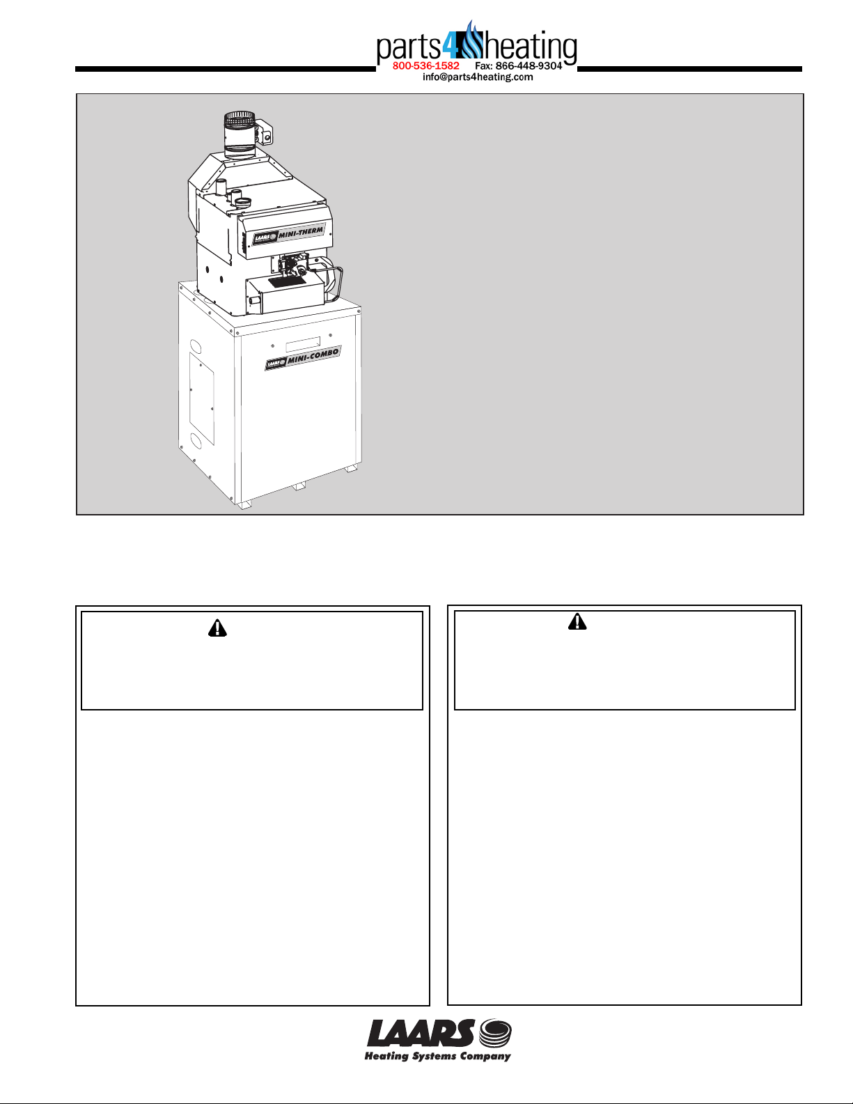
Installation
and Operation
Instructions for
TM
Mini-Combo II
(Models MCT, MCS)
Residential Gas-Fired
Space/Water Heater
NOTE: This manual is to be used in conjunction
with Document 1025, Installation and Operation
Instructions for Mini-Therm II JV boilers.
U.S. Trademark Reg. 2,094,168
China Trademark Reg. 988,311
FOR YOUR SAFETY: This product must be installed and serviced by a professional service technician,
qualified in hot water boiler installation and maintenance. Improper installation and/or operation could
create carbon monoxide gas in flue gases which could cause serious injury, property damage, or death.
Improper installation and/or operation will void the warranty.
If the information in this manual is not
WARNING
followed exactly, a fire or explosion may
result causing property damage, personal
injury or loss of life.
Do not store or use gasoline or other
flammable vapors and liquids in the vicinity
of this or any other appliance.
WHAT TO DO IF YOU SMELL GAS
• Do not try to light any appliance.
• Do not touch any electrical switch; do not
use any phone in your building.
• Immediately call your gas supplier from a
nearby phone. Follow the gas supplier's
instructions.
• If you cannot reach your gas supplier, call
the fire department.
Installation and service must be performed by
a qualified installer, service agency, or gas
supplier.
Assurez-vous de bien suivres les instructions
données dans cette notice pour réduire au
minimum le risque d’incendie ou d’explosion ou
pour éviter tout dommage matériel, toute
blessure ou la mort.
Ne pas entreposer ni utiliser d’essence ni
d’autres vapeurs ou liquides inflammables dans
le voisinage de cet appareil ou de tout autre
appareil.
QUE FAIRE SI VOUS SENTEZ UNE ODEUR DE GAZ:
• Ne pas tenter d’allumer d’appareils.
• Ne touchez à aucun interrupteur. Ne pas vous
servir des téléphones dansle bâtiment où vous
vous trouvez.
• Appelez immédiatement votre fournisseur de
gaz depuis un voisin. Suivez les instructions
du fournisseur.
• Si vous ne pouvez rejoindre le fournisseur de
gaz, appelez le sservice des incendies.
L’installation et l’entretien doivent être assurés par
un installateur ou un service d’entretien qualifié ou
par le fournisseur de gaz.
AVERTISSEMENT
H2077800F
A subsidiary of BRADFORD WHITE Corporation
Page 2

Page 2
LAARS Heating Systems
TABLE OF CONTENTS
SECTION 1.
General Information
1.1 Introduction....................................................... 3
SECTION 2.
Installation
2.1 Location ............................................................ 3
2.2 Heater Placement ............................................. 3
2.3 Piping ............................................................... 5
2.4 Wiring ............................. 5, 6, 7, 8, 9, 10, 11, 12
2.5 Sequence of Operation .................................. 13
SECTION 3.
Replacement Parts
3.1 Ordering Information ...................................... 15
3.2 Parts List ........................................................ 15
Page 3
Mini-Combo II
Page 3
SECTION 1.
General Information
WARNING
This manual supplies information on the application,
installation and operation of the indirect water heater
unit. A complete instruction manual of the operation of
the hydronic boiler (Document 1025) is supplied along
with this manual. Both manuals should be reviewed
completely before proceeding with the installation.
• Failure to follow the instructions provided may result
in personal injury, death or substantial property
damage.
• Any modifications to the boiler, water tank, gas and
water connections, or wiring may void warranty.
• Consult the factory or local factory representative
with any questions or problems regarding this
equipment.
AVERTISSEMENT
Ce manuel donne des renseignements sur
l’application, l’installation et le fonctionnement du
chauffe-eau indirect. Un manuel complet d’instruction
sur le fonctionnement de la chaudière hydronique
(Document 1025) est fourni avec ce manuel. Les deux
manuels doivent être examinés attentivement avant
de procéder à l’installation.
• Si les instructions ne sont pas suivies, il peut en
résulter des blessures personnelles, la mort ou des
dégâts matériels substantiels.
• Toute modification apportée à la chaudière, au
réservoir d’eau, aux branchements de gaz et d’eau
ou aux fils électriques peut invalider la garantie.
• Consultez le représentant de l’usine principale ou
locale pour toute question ou problème concernant
ce matériel.
• Children and elderly, infirmed, or physically
handicapped persons are more likely to be injured
by hot water. Never leave them unattended in a
bathtub or shower. Never allow small children to
use a hot water tap or draw their own bath. If
anyone using hot water in the building fits this
description, or if state/province laws or local codes
require certain water temperature at hot water taps,
take special precautions:
Install an anti-scald valve at water heater or at each
hot water faucet, bath, and shower outlet.
Use lowest practical temperature setting.
• Studies have indicated that dangerous bacteria can
form in potable water distribution system if certain
minimum water temperatures are not maintained.
Contact local health department for more
information.
SECTION 2.
Installation
This installation must conform with the instructions
in this manual and, where applicable:
National Fuel Gas Code (ANSI Z223.1).
National Electric Code (NEC-NFPA 70).
Local, state, provincial, and national codes, laws,
regulations and ordinances.
In Canada - Natural Gas and Propane Installation
Code, CSA B149.1 and the Canadian Electric Code
(CEC - Can/CSA C22.1.
Where the recommendations made in this manual
differ from local or national codes, the local or national
codes take precedence.
1.1 Hazards and Your Safety
- Hot Water Can Scald!
The Consumer Product Safety Commission (CPSC)
and some states/provinces recommend a temperature
setting of 130°F (54°C) or less. The water heater
thermostat is factory set to approximately 120°F (49°C).
If thermostat will be set above factory setting, install an
anti-scald valve at either the water heater or at each hot
water faucet.
• Tempering valves are not anti-scald valves since
they do not have a positive shutoff in case cold
water supply fails. They are not recommended for
shower/tub service. If needed, install an anti-scald
valve at each shower/tub.
• Water heated to a temperature suitable for clothes
washing, dish washing and other sanitizing needs
can scald and cause permanent injury.
2.1 Location
This water heater/boiler unit is not intended for
outdoor installation. Select a convenient location where
water leakage from the tank or connections will not result
in damage to areas adjacent to the appliance or to lower
floors of the structure. When a safe location cannot be
found, install a suitable drain pan under the appliance,
and pipe it to an adequate drain.
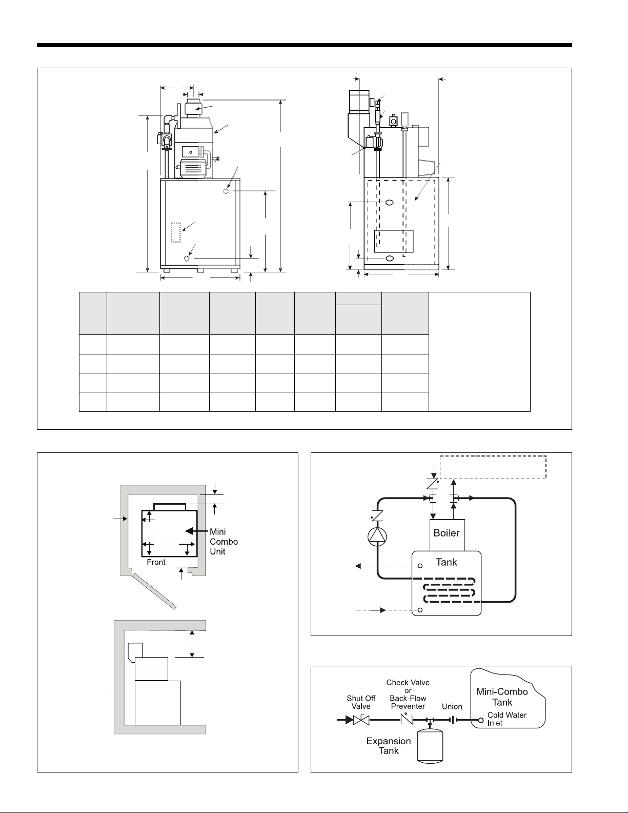
2.2 Heater Placement
The heater must be placed to provide clearances on
all sides for maintenance and inspection. Allow 4 inches
(102mm) on each side for piping access. There must also
be minimum distances maintained from combustible
surfaces. Figure 2 shows minimum clearance from
combustible surfaces. The Mini-Combo unit can be
installed in a closet, as long as the minimum clearances
are maintained. Special attention should be paid to the air
supply opening to the closet. Refer to Table 1.
Page 4
Page 4
B
C
Vent Damper*
Mini-Therm
Boiler
(50-125)
FRONT VIEW SIDE VIEW
54
1372
Tank
Aquastat
Drain
Valve
28
711
Tank
Relief Valve
178
A
24
610
7
Boiler Approx.
CL
Mounted
Pump
24
610
178
Domestic
MC A B C In/Out Gas Inlet/Outlet Weight
Size inches mm inches mm inches mm NPT NPT NPT lbs. kgs
50 58¾ 1492 12½ 318 4 102 1¼ ½ ¾ 258 117
75 58¾ 1492 12½ 318 5 127 1¼ ½ ¾ 274 124
7
System
Check Valve
Check Valve
Outlet
Inlet
610
LAARS Heating Systems
1
24
/
622
(Sizes 50 & 25)
25 635
(Size 75 &
100)
Hot
Water
Tank
31
787
24
Minimum clearances from
combustible surfaces:
left side 2 51
right side 0 0
rear 6 152
front 4 102
top 23 584
100 59¾ 1518 14¼ 362 5 127 1¼ ½ ¾ 280 127
Service clearances:
allow 4 102 on each side
125 59¾ 1518 14¼ 362 6 152 1¼ ½ ¾ 286 130
for piping access.
*Vent damper is optional on some Canadian units.
2
Dimensions shown
in inches mm.
in. mm
Figure 1. Dimensional Information.
2
51
24
610
28
711
4 102
23 584
Space Heating -
Refer to Document 1025
6 152
Hot
Water
Supply
Cold
Water
Supply
Figure 3. Piping Schematic.
Dimensions
shown in inches
mm.
Top Clearance
Figure 2. Closet Installation.
Figure 4. Typical Expansion Tank Installation.
Page 5
Mini-Combo II
Page 5
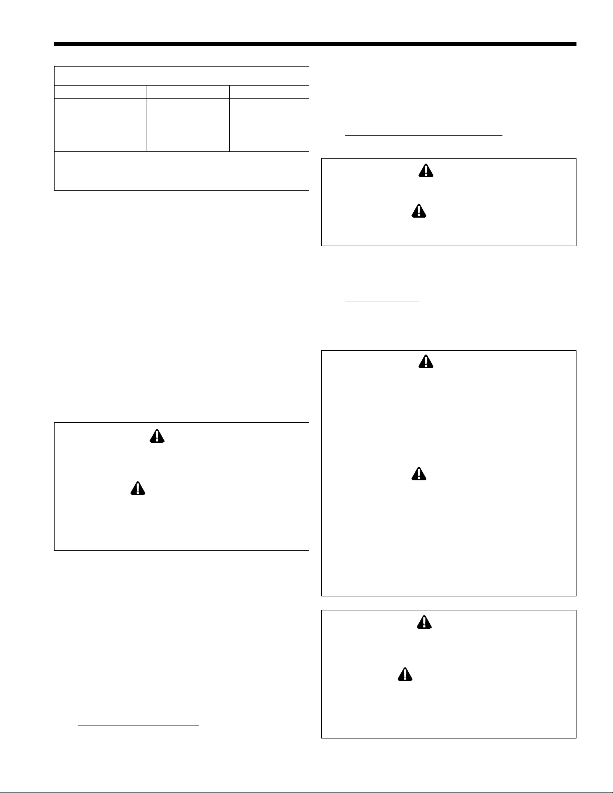
Net Free Area - square inches sq. mm
Model Inside Air Outside Air
MC50 100 645 15 97
MC75 100 645 20 129
MC100 100 645 25 161
MC125 125 807 32 207
Area indicated is for one of two openings: One at floor level and
one at the ceiling, so the total free area would be double the figures
indicated. Refer to Document 1025 for more information
Table 1. Minimum Recommended Air Supply.
2.3 Piping
• To Prevent damage to the unit, all soldering is to be
done prior to assembling the cold and hot water,
and any other connections to the tank.
• Use suitable pipe dope or tape.
• Before piping the boiler to the heating system,
be sure to install the system check valve (provided
with the unit) onto the inlet (return)
tee of the boiler with arrow pointed downward (see
Figure 3).
• If anti-freeze is used in boiler system, local codes
may require a backflow preventer on cold supply
line. Use anti-freeze specifically intended for
hydronic heating system. Inhibited propylene
glycol is recommended.
WARNING
Do not use automotive or ethylene glycol anti-freeze,
or any undiluted anti-freeze. This can cause severe
personal injury, death or substantial property damage.
AVERTISSEMENT
N’utilisez pas d’antigel de moteur ou à base d’éthylène
glycol ou toute sorte d’antigel dilué. Il peut en résulter
des blessures personnelles, la mort ou des dégâts
matériels substantiels.
If a backflow preventer, pressure reducing valve or
check valve is in cold water supply, install an expansion
tank on cold water supply line (Figure 4) to prevent
normal thermal expansion from repeatedly forcing open
the Temperature and Pressure (T&P) relief valve.
T&P relief valves discharge piping must be directed
so that hot water flows away from all persons. Attach
run-off tube to T&P valve and run tube within 6"
(152mm) from floor. No reducing couplings, valves, or
any other type of restriction is to be installed in this line.
This run-off tube must be installed to allow free and
complete drainage of both valve and run-off tube.
Filling Storage Water Tank
1. Open hot water faucet in house to allow air in the
tank and in piping to escape.
2. Open shut-off valve(s) in cold water supply line.
3. Open shut-off valve(s) in hot water supply line.
4. When water discharges from the faucet, close it.
Check for system leaks and repair if necessary.
Filling and connecting boiler pipes:
Consult the JV boiler manual, Document 1025.
CAUTION
Never use water heater/boiler unless it is completely
filled with water.
ATTENTION
N’utilisez jamais le chauffe-eau/chaudière s’il n’est pas
complètement rempli d’eau.
2.4 Wiring
Priority System: Under this wiring the storage tank
will be supplied before space heating. This will insure
that it gets adequate hot water flow from the boiler to
maintain a fully rated delivery of domestic hot water.
CAUTION
In this priority mode, any demand for space heating is
postponed until the storage water tank has reached
set temperature. This delay in supplying the space
heating zones is usually not noticed by the inhabitants
of the living spaces. However, in the event of certain
storage water tank malfunctions, space heating could
be delayed indefinitely. If undetected and uncorrected,
freezing damage to piping could result.
ATTENTION
Dans ce mode de priorité, toute demande de
chauffage est retardée jusqu’à ce que le reservoir à
eau ait atteint la température pré-réglée. Ce retard
n’est normalement pas ressentie pas les habitants des
zones habitables. Cependant, dans le cas d’un
mauvais fonctionnement du réservoir d’eau, le
chauffage pourrait être retardé indéfiniment. Si ce
problème n’est pas détecté et corrigé, la tuyauterie
pourrait geler.
WARNING
Electrical shock can cause severe personal injury or
death. Disconnect power supply to the boiler before
doing any electrical work.
AVERTISSEMENT
Les chocs électriques peuvent causer des blessures
corporelles graves voire la mort. Débranchez la
chaudière avant de commencer les travaux
d’électricité.
Page 6

Page 6
Electrical Connection: (See Figure 5, 6 and 7)
1. Remove the two screws attaching the front cover of
the control box.
2. There are five wires coiled in the area on the right
side of the control box, supplied with wire nuts: 2
black wires twisted together, 2 white wires twisted
together, and a brown wire.
3. Follow Figures 5, 6 and 7. Remove the wire nut
from the two black wires, and connect the hot lead
from a 115 volt power supply to both wires. Secure
the three wires with the wire nut.
4. The two white, neutral wires should be joined to the
other neutral lead coming from the 115 volt power
supply, and the neutral lead coming from the pump
(space heating).
5. The brown wire attaches to the hot side of the space
heating pump.
6. There is a molex connector located on the left side
of the control panel. Connect the vent damper
harness to the molex connector and the other end to
the vent damper receptacle.
LAARS Heating Systems
NOTE: The connection in step 6 should remain intact at
all times, otherwise the boiler will not fire.
Some Canadian units are supplied with vent damper
jumper plug. Do not remove jumper unless vent damper
is to be installed.
Page 7

Mini-Combo II
Page 7
OPTIONAL
AQUASTAT
WALL
THERMOSTAT
(FIELD
SUPPLIED)
TERMINAL
STRIP
JUMPER
POWER VENTER
FAN PROVING
RECEPTACLE
BK - BLACK
W-WHITE
R-RED
Y-YELLOW
BL - BLUE
BR - BROWN
O-ORANGE
P-PURPLE
G-GREEN
IF ANY OF THE ORIGINAL WIRE (AS
SUPPLIED WITH THE APPLIANCE) MUST
BE REPLACED, IT MUST BE REPLACED
WITH APPLIANCE WIRING MATERIAL
SUITABLE FOR 105 DEGREES C OR ITS
EQUIVALENT
SEE DOC. 1056
SPARK IGNITION WIRE
115V-FACTORY WIRED
115V-FIELD WIRED
24V-FACTORY WIRED
24V-FIELD WIRED
P
SWITCH
SENSOR
HIGH
LIMIT
R
R
BR
P
Y
O
24V
COM
SEN
NC
COM
BK
BK
VENT DAMPER
RECEPTACLE*
R
P
NO
TANK
AQUASTAT
Y
BLOCKED
VENT
SAFETY
SWITCH
ROLL-OUT
SAFETY SWITCH
BR
TRANSFORMER
Y
R
BL
Y
Y
TH
TR
24V 115V
Y
Y
BL
R
BL
G
R
ZONE
PUMP
RELAY
BK
TANK
PUMP
RELAY
PILOT BURNER &
THERMOCOUPLE
BK
W
BK
BR
PUMP
(FIELD
SUPPLIED)
BR
Y
HOT
115/60HZ
POWER SUPPLY
NEUTRAL
GROUNDING
CONDUCTOR
W
W
TANK
PUMP
THE BOILER WILL NOT OPERATE WITHOUT
THE AUTOMATIC VENT DAMPER. THE VENT
DAMPER WIRE HARNESS MUST BE
INSERTED INTO THE VENT DAMPER
RECEPTACLE
IN CANADA: SOME UNITS ARE SUPPLIED
*
WITH VENT DAMPER JUMPER PLUG. DO
NOT REMOVE JUMPER UNLESS VENT
DAMPER IS TO BE INSTALLED.
MODEL MCT
H2001700H
GAS VALVE
HW VR8300
Figure 5. Wiring Diagram, Model MCT.
Page 8

Page 8
LAARS Heating Systems
Figure 6. Wiring Diagram, Model MCS, Sizes 50-75.
Page 9

Mini-Combo II
Page 9
Figure 7. Wiring Diagram, Model MCS, Sizes 100-125.
Page 10

Page 10
LAARS Heating Systems
Figure 8. MCT Schematic.
*
*Some Canadian units are supplied with vent damper jumper plug. Do
not remove jumper unless vent damper is to be installed.
Page 11

Mini-Combo II
Page 11
Figure 9. MCS Schematic, Sizes 50-75.
Page 12

Page 12
LAARS Heating Systems
*Some Canadian units are supplied with vent damper jumper plug. Do
not remove jumper unless vent damper is to be installed.
Figure 10. MCS Schematic, Sizes 100-125.
*
Page 13

Mini-Combo II
2.5 Sequence of Operation
115 Volts Supply
Transformer
Vent Damper Motor
Page 13
Tank Stat
(common)
Domestic Demand
(N.C.)
Tank Pump
(energized)
High Limit
Switch
Vent Damper
Open
Power Vent
Fan Switch (optional)
Heating Demand
(N.O.)
Heating Pump
(energized)
Figure 11. Sequence of Operation.
Safety Limit
Switches
Main Gas Valve
(energized)
Boiler On
Page 14

Page 14
LAARS Heating Systems
Figure 12. Parts Identification.
Page 15

Mini-Combo II
Page 15
SECTION 3.
Replacement Parts
3.1 Ordering Information
To order or purchase parts for the Laars products, contact your nearest Laars dealer or distributor. If they cannot
supply you with what you need, contact Laars Customer Service at the address shown on the back cover of this
manual.
Visit our website at www.laars.com for Service Center listings
3.2 Parts List
# Qty Part # Description
1 1 20085700 Weldment, Panel, Base
2 1 20085600 Weldment, Panel, Top
3 1 20086300 Weldment, Panel, Door
4 1 20086400 Panel, Side, Right
5 1 20127900 Weldment, Panel, Side, Left
6 1 20085900 Panel, Rear
7 1 20086500 Panel, Access
8 1 20084000 Bracket, Mounting, Left
9 4 20085400 Bracket, Support, Tank
10 2 P2015400 Tee, Blk, 1¼" x 1¼" x ¾" NPT
11 2 P0014400 Nipple, Black, ¾" NPT x 2.5" LG
12 1 P0014100 Nipple, Close, ¾" NPT
13 1 P2016900 Elbow, Blk, 90°, ¾" x 1" NPT
14 1 P0009300 Elbow, Street, Blk, ¾" NPT
15 1 H2078100 Label, Attention, Toxicity
16 4 P2014800 Fitting, Compress, 7/8" OD x ¾" NPT
17 1 P0008300 Elbow, Blk, 90°, ¾" NPT
18 1 A2085600 Valve, Check, ¾" NPT
19 6 ft. P2015000 Tubing, Copper, Type “L” 7/8" OD
20 1 A2085700 Valve, Drain, Tank, ¾" NPT
21 1 P0025300 Nipple, Brass, ¾" NPT x 2" LG
22 1 E0205000 Temperature Control, Electronic
23 1 A2085400 Valve, Relief, Temp & Pressure
24 1 A2085300 30 Gal Water Tank, Single Wall HX
1 A2085301 30 Gal Water Tank, Double Wall HX
25 2 Field Supplied Nipple, Brass ¾" NPT x 4" LG
26 1 Field Supplied Nipple, Brass 1" NPT x 3" LG
27 2 20087300 Door Latch Assembly
28 1 H2020600 Logo, Mini-Como II
29 1 H2016800 Label, Warning, Installation
# Qty Part # Description
30 2 H0090700 Label, Hot
31 not shown part not sold
32 56 F0024300 Screw, 10-16 x 5/8" LG
33 1 S0064900 Bushing, Nylon, Univ, 7/8" Dia.
36 1 A0066500 Pump, circulator, 1/25 HP
37 1 P0017100 Nipple, Close, Blk, 1¼" NPT
38 1 A2086600 Valve, Check, 1¼" NPT
39 1 H2017100 Tag, Important, Check Valve
40 1 A2087600 Handle, Door
41 1 H2017800 Label, Caution, Setting, Temp
42 2 A2086700 Flange, Pump, ¾" NPT
43 1 Vendor Supplied Well, Immersion, ¾ NPT
45 2 F0035900 Screw, #6-32 x 5/8" LG,
Phillips, Rnd Hd
46 1 Vendor Supplied Nipple, Brass 1" NPT x 2" Long
47 1 P0095000 Tee, 1" x 1" x ¾", Black Iron
48 1 P0071400 Plug, 1" Stainless Steel w/Vibroseal
49 1 20084001 Bracket, Mounting, Right
50 1 A2001500 Pump, Taco, 220V
51 1 E2103100 Sensor, Temperature
52 1 Q0068400 Tubing, Aluminum, 5"
53 2 F0035600 Nut, Speed, Push On
54 4¼ ft E0020900 Conduit, Flex, 3/8"
55 2 E0008300 Nut, Conduit, Lock
56 2 E0008100 Conduit Connector, 3/8"
57 5 E0007700 Wire Nut, 2 #4 Wires
58 4½ ft E0052500 Wire, #18 AWG 3/64", Yellow
59 4½ ft E0051900 Wire, #18 AWG 3/64", White
60 2 E0036100 Bushing
61 1 E0088400 Relay
62 1 E0097700 Relay, Case and Cover
Page 16

A subsidiary of BRADFORD WHITE Corporation
20 Industrial Way, Rochester, NH 03867 • 603.335.6300 • Fax 603.335.3355
1355 Kuehner Drive, Simi Valley, CA 93063 • 800.900.9276 • Fax 800.559.1583
(Sales, Service)
480 S. Service Rd. West, Oakville, Ontario, Canada L6K 2H4 • 905.844.8233 • Fax 905.844.2635
www.Laars.com Litho in U.S.A. © Laars Heating Systems 0511 Document 8001F
H2077800F
 Loading...