

Page 1
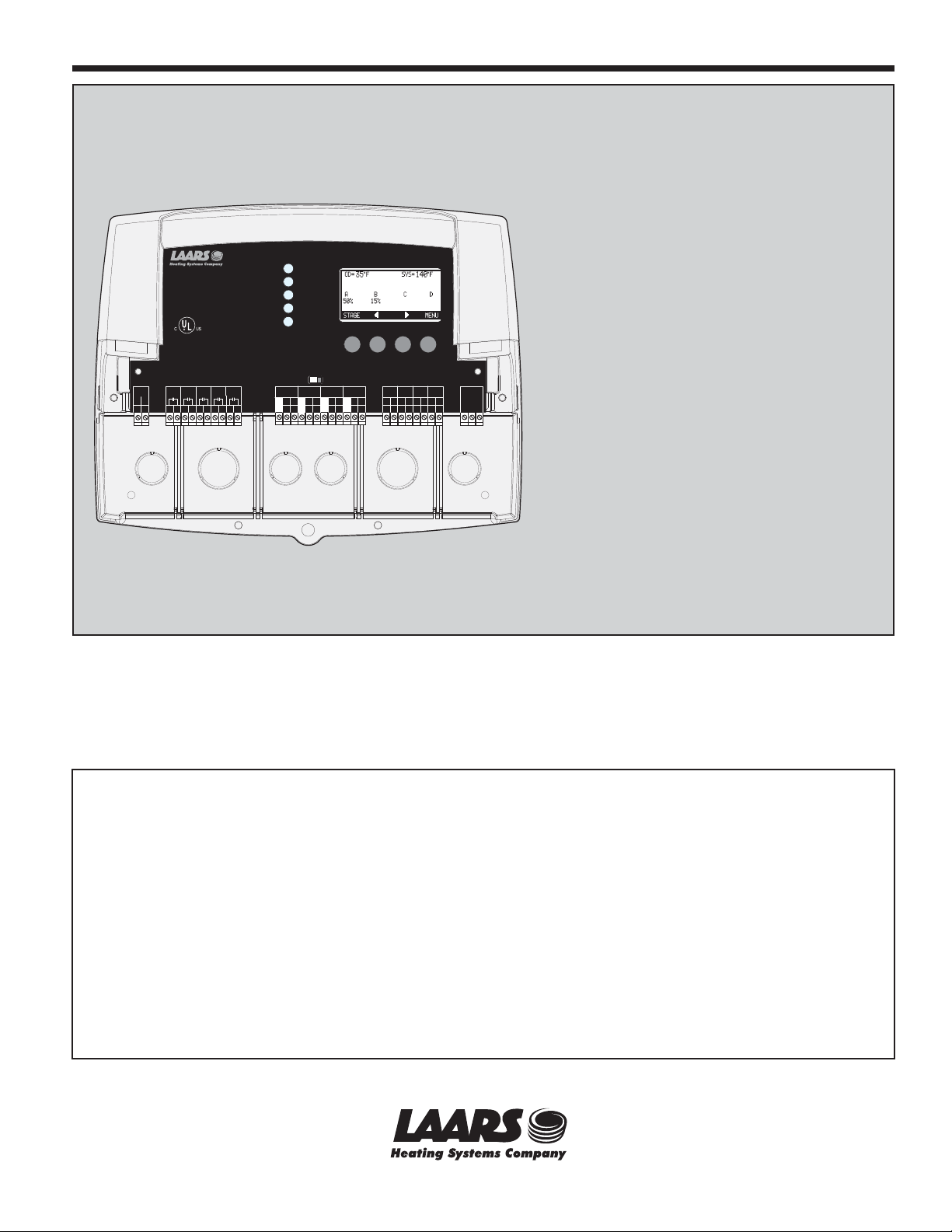
Laars Modulating Controls
Document 4211A
PWR
PWR
L
L
1
1
N
N
2
2
OUTPUT RATINGS:
OUTPUT RATINGS:
120VAC, 6A RESISTIVE
120VAC, 6A RESISTIVE
1A PILOT DUTY, 15A TOTAL
1A PILOT DUTY, 15A TOTAL
FOR ALL CIRCUITS
FOR ALL CIRCUITS
INPUT RATINGS:
INPUT RATINGS:
115VAC 60Hz , 30VA MAX
115VAC 60Hz , 30VA MAX
USE COPPER WIRE,
USE COPPER WIRE,
CLASS 1 WIRE ONLY.
CLASS 1 WIRE ONLY.
ENCLOSED
ENCLOSED
ENERGY
ENERGY
MANAGEMENT
MANAGEMENT
EQUIPMENT
EQUIPMENT
LISTED
LISTED
99RA
99RA
A
B
SYS
A
B
SYS
5
3
6
7
8
4
5
3
6
7
8
4
CAUTION: RISK OF ELECTRIC SHOCK
CAUTION: RISK OF ELECTRIC SHOCK
More than one disconnect switch may be required
More than one disconnect switch may be required
to de-energize the equipment before servicing.
to de-energize the equipment before servicing.
C
D
C
D
9
10
11
12
9
10
11
12
M4
SYSTEM
SYSTEM
A
A
B
B
C
C
D
D
A
A
CUR / VLT
CUR / VLTBCUR / VLTCCUR / VLT
CUR / VLT
CUR / VLT
VLT
mA
GND
GND
mA
VLT
GND
GND
-
-
-
-
+
+
+
+
13
15
16
14
13
16
15
14
FULL MODULATION SEQUENCING
Full Modulation Sequencing Control
RUNPROGRAM
RUNPROGRAM
D
B
D
CUR / VLTCCUR / VLT
mA
VLT
VLT
VLT
mA
mA
GND
GND
mA
mA
mA
mA
VLT
VLT
VLT
GND
GND
mA
-
-
-
-
+
+
+
+
+
+
+
+
+
+
+
+
+
+
18
19
20
23
22
21
17
17
24
23
18
19
20
21
24
22
Mini-MOD
DO NOT APPLY ANY VOLTAGE
DO NOT APPLY ANY VOLTAGE
TO INPUT TERMINALS
TO INPUT TERMINALS
OUTDOOR
SYSTEM
OUTDOOR
TEMP
TEMP
O
T
T
O
26
25
27
26
25
27
---
SYSTEM
TEMP
TEMP
T
T
Modulating
---
EXTENSION
EXTENSION
SHUTDOWN
PROVE
SHUTDOWN
PROVE
/DHW
/DHW
O
O
29
28
29
28
MODULE
MODULE
/SETBACK
/SETBACK
RS-485
RS-485
O
O
O
O
30
31
32
30
32
31
Model M4 and M4-Ext
Output panel to Modulate
up to 16 individual
stages with lead-lag and
manual override capabilities
FOR YOUR SAFETY: This product must be installed and serviced by a
professional service technician, qualified in hot water heater/boiler controls
installation and maintenance. This manual is intended for anyone who will
install, operate or maintain the control system. Before you begin installation
and operation of this control, it is important that you thoroughly review this
manual. Improper installation and operation could result in damage to
equipment and possibly even personal injury. Laars Sequencing Controls are
not intended for use as operation safety limit controls. Another control, that is
intended and certified as a high limit control, must be in the water heater/boiler
control circuit.
Page 2

Page 2 LAARS Heating Systems
Contents
M4 LAYOUT . . . . . . . . . . . . . . . . . 3
M4 OVERVIEW . . . . . . . . . . . . . . . 4
UNDERSTANDING OPERATION CONCEPT 5
Reset Ratio/Outdoor Reset . . . . . . . . . .5
INITIAL PILOT PROGRAM . . . . . . . . . 6
Making Sure You Have the Right Control . 6
Selecting the System Features. . . . . . . 6
INSTALLATION . . . . . . . . . . . . . . . 7
Mounting the Enclosure . . . . . . . . . . 7
Install the Sensors . . . . . . . . . . . . . 8
Heating System Sensor (HSS) Installation. . .8
Outdoor Sensor Installation . . . . . . . . . . 8
Wiring. . . . . . . . . . . . . . . . . . . . 9
Wiring the Power (Terminals 1, 2) . . . . . . . 9
Wiring the Sensors . . . . . . . . . . . . . . . 9
Wiring the Shutdown (Terminals 31, 32) . . . .9
Wiring the System Prove (Terminals 29, 30) 10
Wiring the Domestic Hot Water Call DHW
(Terminals 29, 30) . . . . . . . . . . . . . . 10
Wiring the System Output (Terminals 3, 4) . . 10
Wiring the Boilers . . . . . . . . . . . . . . 10
Wiring to Modulating Motors . . . . . . . . . 11
Connecting to the M4-Extension Panels . . . 11
MENU SEQUENCE . . . . . . . . . . . . . 12
Startup Settings . . . . . . . . . . . . . . 14
Program Change Settings . . . . . . . . . . 14
Startup Sequence . . . . . . . . . . . . . . 14
Sensor Type . . . . . . . . . . . . . . . . . 14
EMS Input Mode (Available in Set Point Only) 14
Selecting the Output Type . . . . . . . . . . 14
Selecting the Modulating Mode . . . . . . . 15
Prove/Domestic Hot Water (DHW) . . . . . . 15
Setback Mode . . . . . . . . . . . . . . . . 15
Boost Mode . . . . . . . . . . . . . . . . . 15
Sensor Fault . . . . . . . . . . . . . . . . . 15
Operating Settings . . . . . . . . . . . . . 16
Program Change Settings . . . . . . . . . . 16
Season . . . . . . . . . . . . . . . . . . . . 16
Set Point . . . . . . . . . . . . . . . . . . . 16
Reset Ratio. . . . . . . . . . . . . . . . . . 16
Outdoor Cutoff Temperature . . . . . . . . . 17
Offset . . . . . . . . . . . . . . . . . . . . . 17
Minimum Water Temp . . . . . . . . . . . . 17
Maximum Water Temp . . . . . . . . . . . . 18
System Settings . . . . . . . . . . . . . . 18
Gain . . . . . . . . . . . . . . . . . . . . . 18
Lead Boiler Rotation . . . . . . . . . . . . . 18
Purge Delay . . . . . . . . . . . . . . . . . 19
Lag Delay . . . . . . . . . . . . . . . . . . 19
Standby Time. . . . . . . . . . . . . . . . . 19
System Run-On . . . . . . . . . . . . . . . 19
Setback. . . . . . . . . . . . . . . . . . . . 20
Last Stage Hold . . . . . . . . . . . . . . . 20
Day/Night Schedules . . . . . . . . . . . . . 21
Set Time . . . . . . . . . . . . . . . . . . . 21
History . . . . . . . . . . . . . . . . . . . 21
Maintenance . . . . . . . . . . . . . . . . 22
System & Outdoor Sensor Trim . . . . . . . 22
Soft-Off Delay . . . . . . . . . . . . . . . . 22
Output Trim. . . . . . . . . . . . . . . . . . 22
Configuration . . . . . . . . . . . . . . . . . 23
Display . . . . . . . . . . . . . . . . . . . 23
Display Boiler Modulation Status. . . . . . . 23
Display Messages . . . . . . . . . . . . . . 23
Boiler Stage Settings . . . . . . . . . . . . 24
Mode . . . . . . . . . . . . . . . . . . . . . 24
Ignition %. . . . . . . . . . . . . . . . . . . 25
Modulation Start % . . . . . . . . . . . . . . 25
Copy Settings - Boiler A Only . . . . . . . . 25
TROUBLESHOOTING. . . . . . . . . . . . 26
SPECIFICATIONS . . . . . . . . . . . . . . 28
Page 3
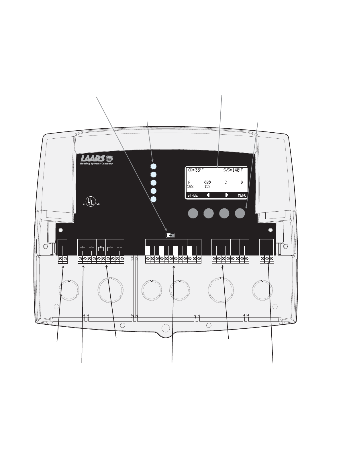
M4 LAYOUT
Page 3LAARS Modulating Controls M4 & M4-EXT
Program Switch to restrict access to
function changes. This switch is
covered with Wiring Enclosure.
LED indicates the
associated relay status.
OUTPUT RATINGS:
OUTPUT RATINGS:
120VAC, 6A RESISTIVE
120VAC, 6A RESISTIVE
1A PILOT DUTY, 15A TOTAL
1A PILOT DUTY, 15A TOTAL
FOR ALL CIRCUITS
FOR ALL CIRCUITS
INPUT RATINGS:
INPUT RATINGS:
115VAC 60Hz , 30VA MAX
115VAC 60Hz , 30VA MAX
USE COPPER WIRE,
USE COPPER WIRE,
CLASS 1 WIRE ONLY.
CLASS 1 WIRE ONLY.
ENCLOSED
ENCLOSED
ENERGY
ENERGY
MANAGEMENT
MANAGEMENT
EQUIPMENT
PWR
PWR
L
L
1
1
EQUIPMENT
LISTED
LISTED
99RA
99RA
A
SYS
A
SYS
N
N
2
2
5
3
4
5
3
4
CAUTION: RISK OF ELECTRIC SHOCK
CAUTION: RISK OF ELECTRIC SHOCK
More than one disconnect switch may be required
More than one disconnect switch may be required
to de-energize the equipment before servicing.
to de-energize the equipment before servicing.
D
C
B
C
D
9
10
11
8
9
10
11
678
6
7
B
12
12
M4
SYSTEM
SYSTEM
A
A
B
B
C
C
D
D
A
A
CUR / VLT
CUR / VLT
GND
GND
-
-
13
13
B
CUR / VLTBCUR / VLTCCUR / VLT
CUR / VLT
mA
mA
VLT
GND
mA
mA
VLT
GND
-
-
+
+
+
+
+
+
15
16
14
17
15
16
14
17
The digital display shows the system status, set point,
lead stage <in brackets>, and status of each stage.
To view and adjust settings, press the appropriate buttons.
Buttons function is presented on
Bottom Row of display.
FULL MODULATION SEQUENCING
Full Modulation Sequencing Control
---
---
DO NOT APPLY ANY VOLTAGE
DO NOT APPLY ANY VOLTAGE
OUTDOOR
OUTDOOR
TEMP
TEMP
VLT
VLT
T
T
+
+
25
24
25
24
TO INPUT TERMINALS
TO INPUT TERMINALS
PROVE
SYSTEM
SYSTEM
PROVE
/DHW
TEMP
/DHW
TEMP
T
O
O
26
26
O
O
O
T
O
30
29
28
27
30
29
28
27
SHUTDOWN
SHUTDOWN
/SETBACK
/SETBACK
O
O
32
31
32
31
EXTENSION
EXTENSION
MODULE
MODULE
RS-485
RS-485
VLT
VLT
+
+
18
18
RUNPROGRAM
RUNPROGRAM
C
CUR / VLT
mA
GND
mA
GND
-
-
+
+
20
19
19
20
VLT
VLT
+
+
21
21
D
D
CUR / VLT
mA
mA
GND
mA
mA
GND
-
-
+
+
+
+
23
22
23
22
120VAC Power
System Output controls
pumps, valves, or other
system components.
Four N.O. Boiler startup relay
outputs. Each is wired in series
with each boiler's limit circuit.
Four modulation outputs can be 0-10V,
0-5V, 2-10V, 1-5V, or 4-20ma. Go to
Startup Menu to determine the type of
output for each stage.
When connecting Outdoor and System
Sensors, no Polarity is observed.
Prove terminals must be connected
for M4 to operate boilers.
Connect Extension panels to
add additional stages using
a 6 pin phone line only (cable
provided with M4-Extension).
Page 4

Page 4 LAARS Heating Systems
M4 OVERVIEW
SEQUENCES UP TO 4 FULLY MODULATING STAGES.
The M4 is the perfect control whenever multiple fully modulating stages are required for hydronic heating applications. The M4 controls
the on/off and the modulation of each stage to maintain precise system set point control.
PID TYPE LOGIC
The M4’s control algorithms allow it to look at the rate of change in the system. If the system temperature is changing quickly, the M4
will react quickly to adjust the modulating stages’ output. If the system temperature changes slowly, the M4 will make slow and gradual
output adjustments. Therefore, the M4 adapts to specific system requirements and minimizes fluctuations around the set point.
CONTROLS 0-10 V, 0-5 V, 2-10V, 1-5V, OR 4-20 MA MODULATING MOTORS
The M4 is designed to accurately control the output from 0 to 100% of modulation for each of these different types of motors. One M4
can even control a variety of the above different motors.
ONLY ONE SENSOR
When Set Point sensor type is selected, the M4 requires only one sensor located in the common output header of all stages. However,
when Reset is selected, an additional Outdoor Sensor is required for Outdoor Reset Ratio input.
DIGITAL DISPLAY OF ALL SYSTEM SETTINGS
The M4’s alphanumeric digital display names each system parameter in simple English and shows its precise value. The easy to follow
menu system allows users to quickly make changes to any system setting without having to learn any specialized codes or keyboard
commands.
AUTOMATIC ROTATION AMONG STAGES
Rotating the first stage to be activated on a call for output promotes even wear on each stage. The M4 has three modes of rotation: Manual,
Last On, or Time. The Time rotates the lead stage every selected time period from every hour to every 60 days.
OUTDOOR RESET
The M4 has a hydronic outdoor temperature reset function. This allows the M4 to change the set point based on outdoor temperature.
Furthermore, additional settings have been added to fine tune this operation, like Offset, Minimum, and Maximum Water Temperature
and night setback schedule.
STANDBY BOILERS
Each of the M4 stages can be configured as a Standby boiler with an adjustable Standby delay. A boiler can be used as a backup during
extended large demand periods.
SYSTEM OUTPUT
In Set Point mode, this output can be used to activate a system pump, combustion air damper, or perform any other function that is required
when any stage is active. In Outdoor Reset mode, the System Output will activate whenever the outdoor temperature is below the Outdoor
Cutoff setting. A System Prove input checks the status of components activated by the System output before stages can be activated.
STAGING (NORMAL) OR PARALLEL MODULATION
The M4 can stage boilers as needed. That will allow it to increase the modulation on the lead boiler. When the lead boiler reaches its
modulation start point adjustment and does not satisfy the load, the M4 will start the next boiler and so on... Moreover, the M4 allows
for a parallel mode that can modulate several boilers together as a one large boiler. This mode is useful for boilers with lower water
content, which are usually more efficient at lower firing points.
ADD UP TO 16 BOILER STAGE (OPTIONAL)
As a stand-alone, the M4 is designed to control four modulating boilers. However, it has the capability of expanding its control to two
extension panels each with six boiler stages. Thus, the M4 can control a total of up to 16 boiler stages.
Page 5
UNDERSTANDING OPERATION CONCEPT
Outdoor Temperature (in °F)
70 605040 20
30 0 -10
10 -20
100
120
110
130
140
150
160
180
170
190
200
210
220
1:3 1:2 1:1.5
1:1.25
1:1
1.25:1
1.5:1
2:1
3:1
4:1
Water Temperature (in °F)
Reset Ratio Curves
1:4
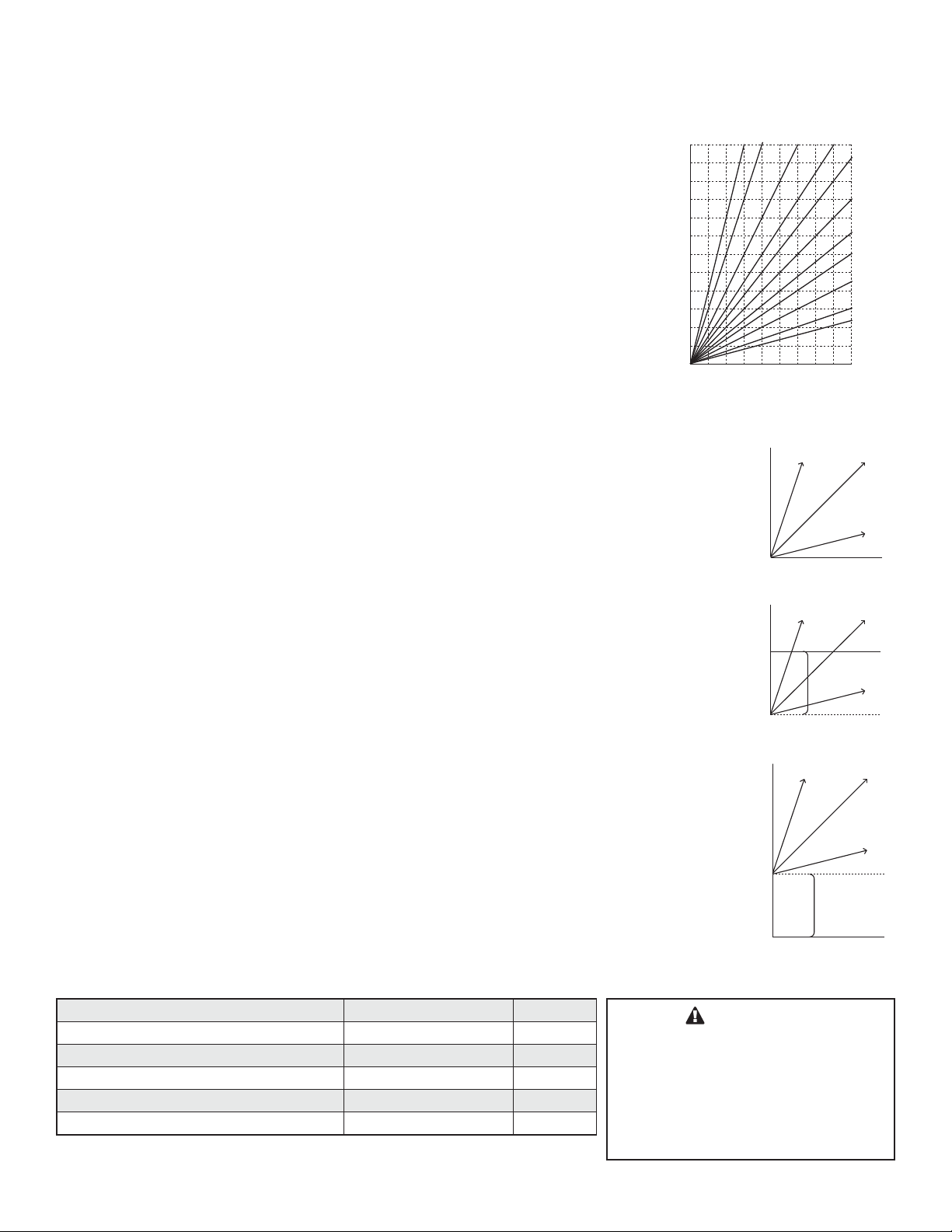
The M4 has multiple operating modes that satisfy most hydronic systems. It can change the
System Set Point based on outdoor temperature (Outdoor Reset) or it can modulate its stages
to achieve an adjustable fixed Set Point.
In Outdoor Reset, the M4 controls a hot water heating system to provide a building with
comfortable and even heat levels. The M4 varies the temperature of the circulating heating
water in response to changes in the outdoor temperature. The heating water temperature is
controlled through the modulation of stages.
The M4 also controls the system circulating pump with an adjustable Outdoor Cutoff. When
the outdoor temperature is above Outdoor Cutoff, the pump is off and no heating water is
circulated through the system. When the outdoor temperature drops below the Outdoor Cutoff,
the system pump relay is activated and the heating water circulates through the system. The
temperature of the heating water is controlled by the Reset Ratio, Water Offset, and changes
with Outdoor temperature.
Page 5LAARS Modulating Controls M4 & M4-EXT
RESET RATIO/OUTDOOR RESET
When a building is being heated, heat escapes through the walls, doors, and windows to
the colder outside air. The colder the outside temperature, the more heat escapes. If you
can input heat into the building at the same rate that it is lost out of the building, then
the building temperatures will remain constant. The Reset Ratio is an adjustment that
lets you achieve this equilibrium between heat input and heat loss.
The starting point for most systems is the 1.00 (OD):1.00 (SYS) (Outdoor Air
Temperature : Heating Water Temperature) ratio. This means that for every degree
the outdoor temperature drops, the temperature of the heating water will increase one
degree. The starting point of the curves is adjustable, but comes factory selected at
70
°F Outdoor Temp. and 100°F Water Temp. For example with a 1.00 (OD):1.00 (SYS)
ratio, if the outdoor temperature is 50
the starting point of 70°F. Therefore, the heating water temperature will increase 20° to
120°F.
Each building has different heat loss characteristics. A very well insulated building will
not lose much heat to the outside air, and may need a Reset Ratio of 2.00 (OD):1.00
(SYS) (Outdoor:Water). This means the outdoor temperature would have to drop
2 degrees to increase the water temperature 1 degree. On the other hand, a poorly
insulated building with insufficient radiation may need a Reset Ratio of 1.00 (OD):2.00
(SYS). This means that for each degree the outdoor temperature dropped the water
temperature will increase 2 degrees. The M4 has a full range of Reset Ratios to match
any buildings heat loss characteristics.
°F, this means the temperature has fallen 20° from
130
120
110
Water Temperature
100
70 405060
Outdoor Temperature
110
100
90
Water Temperature
80
70 405060
Outdoor Temperature
150
140
130
Water Temperature
120
1:4
1:4
1:4
-20 Offset
1:1
4:1
1:1
4:1
1:1
4:1
A heating curve that relies not only on Outdoor temperature but also on type of radiation
types of radiation based on average building insulation and heat loss. The contractor
can fine tune these adjustments based on the specific building need.
Type of Radiation in Building Reset Ratio Offset
Radiators (Steel & Cast Iron) 1.00 (OD) : 1.00 (SYS) 0˚F
Baseboard (Finned copper tube& Cast Iron) 1.00 (OD) : 1.00 (SYS) 0˚F
Radiant (High Mass/Concrete) 4.00 (OD) : 1.00 (SYS) -10˚F
Radiant (Low Mass/Joists) 2.00 (OD) : 1.00 (SYS) -10˚F
Fan Coils & Air Handlers 1.00 (OD) : 1.00 (SYS) 20˚F
will improve heat comfort. The following are suggested initial settings for different
90
100
70 405060
+20 Offset
Outdoor Temperature
WARNING
When controlling a non condensing
boiler directly without the use of a
mixing valve, minimum boiler water
temperature must be set to boiler
manufacturer specifications. In that
case, system temperature must not go
below such temperature.
Page 6

Page 6 LAARS Heating Systems
MAKE SURE YOU HAVE THE RIGHT CONTROL
If you need the M4 to do additional tasks that either are not listed or do not know how to configure them, contact LAARS.
INITIAL SETUP
Setting an Initial Program will ease the configuration of the M4 and will give the opportunity to utilize many of the energy saving features
and give more comfortable heat when needed.
The program should consist of the following:
• Selecting the features that your system can utilize,
• Installation: Install the Control, switches and sensors,
• Setting the System Startup,
• Setting the System Settings,
• Setting the Stages
• Adjusting Reset Ratio and Water Offset (In Reset Mode Only)
SELECTING THE SYSTEM FEATURES
The M4 has been designed with Hydronic building heating as the primary purpose. With this in mind, many of the M4 features can be
utilized to ease, enhance and improve your system performance. Some of these features are listed in this section.
OUTDOOR RESET OR SET POINT
• The M4 can control the System Temperature either by adjusting the calculated temperature according to the Outdoor Temperature
(Outdoor Reset) or by maintaining an adjustable Set Point. The earlier relies on an Outdoor Sensor (supplied with the control) and
achieves better fuel savings in addition to better comfort.
NUMBER OF STAGES
• The M4 can be configured to control up to 4 modulating boilers. It can control up to 16 boiler stages using a maximum of two M4
Extension Panels
MODULATION MODE
•
The M4 can stage boilers using one of two methods. Normal Modulation Mode, allows it to increase the modulation of the lead
boiler. When the lead boiler reaches its modulation start point adjustment and does not satisfy the load, the M4 will start the next
boiler and so on. This mode targets boilers that can run more efficient at higher modulation rates.
• The Parallel Modulation Mode can modulate several boilers together as a one large boiler. This mode is useful for boilers that are
more efficient at lower firing points.
MODULATING SIGNAL
•
The M4 is designed to accurately control the output from 0 to 100% of modulation for each of these different types of motors. One
M4 can even control a variety of the above different modulation motors.
AUTOMATIC ROTATION AMONG BOILERS
• Rotating the first burner to be activated on a call for output promotes even wear on all burners. The M4 has three modes of rotation:
Manual, Last-ON, or Time automatically rotating every selected time period from every hour to every 60 days.
STANDBY BOILER
•
Any boiler can be configured as a Standby boiler. It withholds a specific boiler from being included in the Lead Rotation. However,
the Standby boiler will be fired only as a backup when all other stages combined cannot satisfy the demand and after an adjustable
delay period.
SETBACK OR DAY/NIGHT SCHEDULING
Two Setback modes are available for the M4:
• The Day/Night Scheduling provides an adjustable time-based schedule for the Setback.
• The Setback mode uses an external signal to switch the operation of the M4 in and out of setback mode.
Page 7
Page 7LAARS Modulating Controls M4 & M4-EXT
System Run-On
• This feature lets the M4 run the SYS relay for a longer period after the boilers have been turned off. When this relay is used to
control a pump, it helps in dissipating the excess heat from the boilers combustion chamber.
INSTALLATION
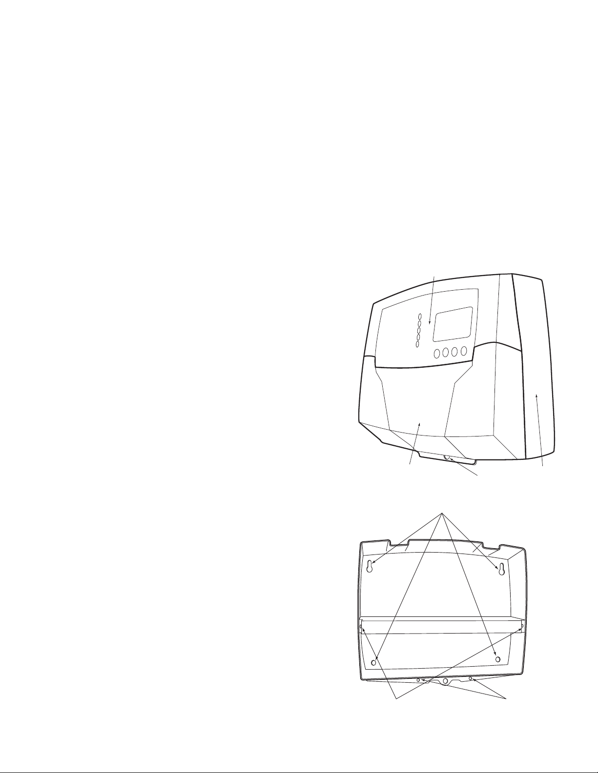
Each of the M4 or M4-Extension consists of three primary enclosure components.
• The Enclosure Display Module: contains the display, buttons, LEDs and electric wiring terminals. It has two screws to hold it to
the base. A program configuration switch, used to adjust M4 settings, is placed above the terminals. This switch is enclosed with
the enclosure wiring cover for security. Wiring terminals are of the plug-in type to ease installation and removal.
• The Enclosure Base: contains the holes to mount and hold the control against the wall or any flat surface. All other enclosure
components mount on the base. The bottom section of the Enclosure Base contains the wiring chamber with knockouts on the
bottom to easy installation.
• The Enclosure Wiring Cover: seals the wires from the external environment. It has two screws to hold it the base and a hole to
secure a lock on the wiring enclosure. A plastic web that separates the wiring chamber into high and low volt sections has been
provided.
MOUNTING THE ENCLOSURE
• Select a location near the equipment to be controlled.
• The surface should be flat, and be sufficiently wide and strong to hold the
M4 or M4-Extension.
• Keep the control away from extreme heat, cold, or humidity. Ambient
operating temperature is from 20 to 120°F.
• Remove the Enclosure Wiring Cover from the control enclosure by
removing the two bottom screws.
• Remove the Enclosure Display Module by removing the middle screws.
• Screw the Enclosure Base to the surface through the upper and lower
mounting holes on the back of the enclosure.
• Replace the Enclosure Display Module and replace the middle screws.
• Do not replace the enclosure wiring cover until all wiring is done.
Page 8
Page 8 LAARS Heating Systems
INSTALL THE SENSORS
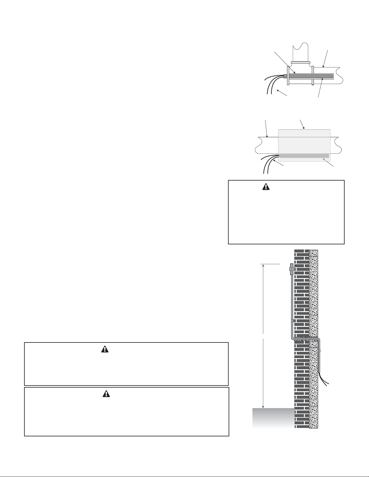
HEATING SYSTEM SENSOR (HSS) INSTALLATION
LOCATING HSS
• Put the Heating System sensor approximately 10' feet past the last boiler on
the common supply header but before any major takeoffs.
• The sensor must be located where it sees the output of all the boiler stages.
If a boiler is piped so that the sensor does not see its output, the M4 will not
sequence the boilers correctly.
• Only use a Standard Brass Tube sensor (HT #904015-00 or equivalent).
• The sensor wires can be extended up to 500' using a shielded 2-conductor
cable (Belden #8760 or equivalent). Do not ground the shield at the sensor
but at the panel using one of the terminals marked with an “O”.
• Do not run sensor wires in conduit with line voltage wiring.
IMMERSION HEATING SYSTEM SENSOR (HSS) INSTALLATION
• Install a 3/8"ID 1/2"NPT immersion well (HT #350147-00 or equivalent).
• Insert the sensor probe of the supplied sensor into the well.
STRAP-ON HEATING SYSTEM SENSOR (HSS) INSTALLATION
• Strap the sensor to the pipe using metal clamps. Do not over tighten the
clamp.
• Strap pipe insulation around the sensor and pipe.
Immersion Heating System Sensor
Immersion Well
3/8" ID 1/2" NPT
Shield
Heating System
Sensor
Strap-On Heating System Sensor
Common Supply Pipe
Pipe Insulation
Shield
Common Supply Pipe
Sensor Probe
Sensor Probe
CAUTION
If the HSS can not sense the correct
heating system water temperature being
supplied to the building, the M4 will not
provide comfortable heat levels. Be sure
the HSS is located on a main supply pipe
which can not easily be isolated from the
system.
OUTDOOR SENSOR INSTALLATION
• Only use the LAARS sensor included with the unit.
• Locate the sensor in the shade on the north side of the building. The sensor
should never be in direct sunlight.
• Be sure the location is away from doors, windows, exhaust fans, vents, or
other possible heat sources.
• The sensor should be mounted approximately 10' feet above ground level.
• Mount the sensor clip base to the outside of the building. Insert the sensor in
the middle and snap close the clip on the sensor.
• The sensor wires can be extended up to 500' using shielded 2-conductor
cable. Do not ground the shield at the sensor but at the panel using one of the
terminals marked with an “O”.
• Do not run sensor wires in conduit with line voltage wiring.
WARNING
The M4 is an operating control only. All boilers must have all safety
and limit controls required by code. It is the responsibility of the
installer to verify that all the safety and limits are working properly
before the M4 is installed.
CAUTION
Determining the proper location for the Outdoor Sensor is very
important. The M4 will base the heat on the outdoor temperature
information it receives from this location. If the sensor is in the
sun, or covered with ice, its reading will be different from the actual
Outdoor temperature (OD).
Page 9
Page 9LAARS Modulating Controls M4 & M4-EXT
O
3
WIRING
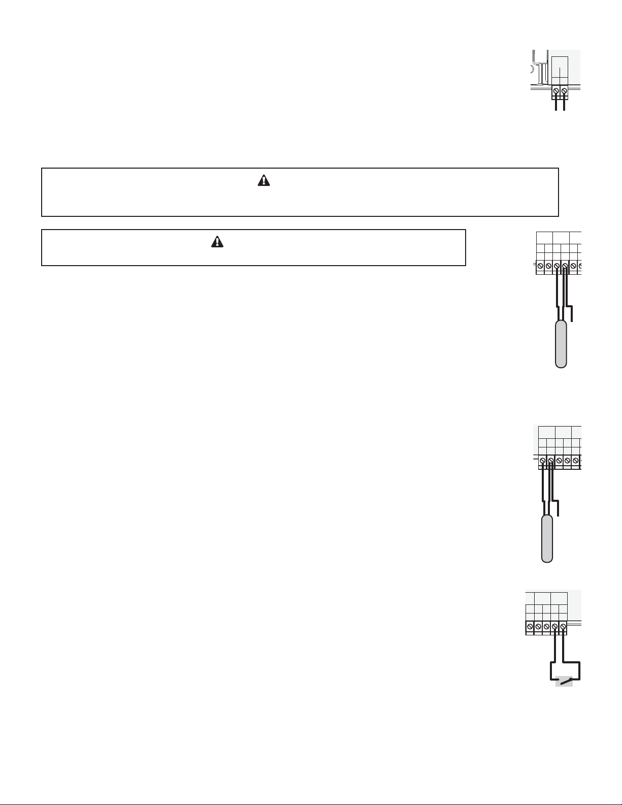
WIRING THE POWER (TERMINALS 1, 2)
• Bring the 120VAC 60Hz power wires through the bottom Knockout of the enclosure.
• Class 1 voltages must enter the enclosure through a different opening from any Class 2 voltage wiring.
• Connect the hot line to terminal marked L.
• Connect the neutral line to the terminal marked N.
• LAARS recommends installing a surge suppressor on the power source to the M4.
WARNING
Class 1 voltages must enter the enclosure through a different opening from any Class 2 voltage wiring.
LAARS recommends installing a surge suppressor on the power source to the M4.
WARNING
Connect the shield at the control terminal end and cut the shield wire at the sensor
WIRING THE SENSORS
SYSTEM SENSOR WIRING (TERMINALS 27, 28)
• A M4 must be connected to a temperature sensor located in the common header.
• The M4 is designed to be connected to a HT #904015-00 temperature sensor for immersion in a 3/8ID well (HT
#350147-00 or equivalent). Contact the factory for additional temperature sensor options.
• Temperature sensor wires can be extended up to 500’ by splicing shielded 2-conductor cable (Belden #8760 or
equivalent).
• Temperature sensors have no polarity. Connect the two wires from the sensor to the M4 terminals marked
SYSTEM TEMP 27, 28.
• Connect the sensor shield to the circled terminal 28 with one of the sensor wires.
OUTD
2
Powe
EM
T
T
5
OR
O
P
O
2
PWR
L
1
20VAC
1
6
27
r
SYS
T
T
Line
S
EM
N
2
ource
TEM
P
O
8
2
ensor
stem S
Sy
Neutral
O
PR
W
/DH
9
2
led
nsor Shi
Se
E
V
3
OUTDOOR SENSOR WIRING (TERMINALS 25, 26)
• When Outdoor Reset is selected, the M4 will vary the system Set Point based on outdoor temperature.
• Whether in Set Point or Outdoor Reset modes, the outdoor sensor can be used as an Outdoor Cutoff.
The M4 will disable all Boilers when the outdoor temperature is above the adjustable Outdoor Cutoff
temperature. This feature will automatically be activated when an outdoor sensor is connected.
• For an outdoor sensor use a LAARS outdoor sensor (HT #904015).
• The sensor wires can be extended up to 500’ using shielded 2-conductor cable (Belden #8760 or equivalent).
• Temperature sensors have no polarity. Connect the wires from the outdoor
sensor to the M4 terminals marked OUTDOOR TEMP - 25, 26.
• Connect the shield to the circled terminal 26 with one of the sensor wires.
WIRING THE SHUTDOWN (TERMINALS 31, 32)
• This feature can be used whenever it is desirable to turn off the M4 stage outputs from a remote location or
another controller (i.e. EMS input).
• When the Shutdown feature is enabled by closing a dry contact, all active boilers will immediately modulate
down to low then off. The lead boiler will remain in low for a Soft-Off period; default setting is 45 seconds,
and then turn off.
• The System Output relay will remain active until the System Delay is over and then it will turn off.
• The Shutdown signal must be a dry contact only. No voltage can be placed across the SHUTDOWN terminals.
• Bring the two wires from the dry contact to the terminals marked SHUTDOWN- 31,32.
R
O
STEM
SY
MP
E
T
T
O
27
led
Shi
or
s
en
S
W
O
TD
U
SH
ETBACK
/S
O
31
32
Shutdown
ign
S
V
O
PR
W
/DH
O
29
28
N
al
O
OUTD
MP
E
T
T
26
25
nsor
doorSe
t
Ou
VE
TEM
O
PR
W
MP
H
D
/
O
O
30
29
28
Page 10
Page 10 LAARS Heating Systems
1
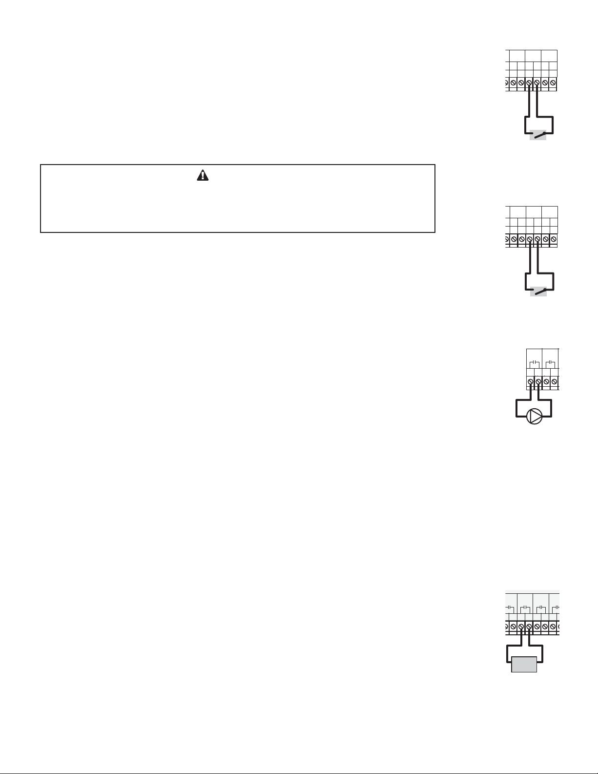
WIRING THE PROVE (TERMINALS 29, 30)
• The Prove feature is provided to check system component operation and must be selected in the Startup Menu.
• A typical use of this feature is to check for flow before firing any boiler.
SYS
EMP
T
T
ORO
6
28
27
N
W
O
TD
U
SH
E
V
O
PR
K
/SETBAC
/DHW
O
31
30
32
29
TEM
• If the PROVE input is open on a call, the M4 will enable only the System Output. All Boiler outputs will be
off when the PROVE input is open.
• A factory-installed jumper provides the System Prove signal. Do not remove the jumper unless it will be
replaced by a System Prove signal or use the terminals for DHW call.
• Bring the two wires from the dry contact to the terminals marked PROVE - 29, 30. No voltage can be placed
across the PROVE terminals
Pr
ove Si
gnal
WARNING
The PROVE input can not be used as a safety limit. All equipment must have its own
certified limit and safety controls as required by local codes. If Prove is selected in the
startup menu, no boiler stage will start unless Prove terminals are shorted. DO NOT
remove the PROVE jumper supplied unless replacing it with a Prove signal.
WIRING THE DOMESTIC HOT WATER CALL DHW (TERMINALS 29, 30)
• DHW can be used to raise system Set Point to 200°F or Maximum Water temperature, whichever is lower.
DHW with or without Priority must be selected in the Startup Menu.
• DHW Call terminals are dry contact N.O. terminals.
• Wire an aquastat or other controls to provide closure on the DHW Call terminals.
• Remove the jumper on the DHW terminals for proper operation.
R
TEM
SYS
EMP
T
T
O
6
28
27
D
O
PR
W
H
/D
29
HW S
W
O
TD
U
SH
E
V
ETBACK
/S
O
O
31
30
32
ignal
N
WIRING THE SYSTEM OUTPUT (TERMINALS 3, 4)
System Output Operation in Set Point Mode
• The SYS output relay will energize whenever the outdoor temperature drops below the Outdoor Cutoff or
whenever a boiler output is active. If no outdoor sensor is connected and the last boiler relay has de-energized,
the SYS relay will remain energized for a period set by the System Run-On.
• No Boilers will be activated until the prove input is shorted. If a Prove is not required, the factory-installed
jumper should remain connected.
• A typical use of the SYS output is to activate a system pump starter. The pump can run whenever there is a call
for heat. When heat is no longer required, the pump will stay active for an adjustable Pump Run-On delay.
System Output Operation in Reset Mode
• The SYS output relay will energize whenever the outdoor temperature is below the Outdoor Cutoff.
• The SYS will remain constantly energized while the outdoor temperature is below the Outdoor Cutoff.
• When the outdoor temperature rises 2°F above the Outdoor Cutoff, the SYS output will remain energized for
the period set by the System Run-On.
• The SYS output has one Normally Open (N.O.) relay contact.
• The N.O. contacts are dry contacts only. They do not source any voltage.
• Class 1 voltages must enter the enclosure through a different opening from any Class 2 voltage wiring.
• Each N.O. contact is capable of switching 6A resistive at 120VAC.
WIRING THE BOILERS
WIRING THE BOILER OUTPUTS (A TERMINALS 5, 6), (B TERMINALS 7, 8), ...
• Each Boiler output (A through D) has one Normally Open (N.O.) relay contact.
• The N.O. contacts are dry contacts only. They do not source any voltage.
• Each N.O. contact is capable of switching 6A resistive at 120VAC.
• Total output of all Boilers, including the SYS, must not exceed 15A.
• Wire the N.O. relay contacts in series with the unit’s limit circuit.
• Class 1 voltages must enter the enclosure through a different opening from any Class 2 voltage wiring.
o
A
678
Boiler
S
rPu
Boiler
Ou
te
s
y
B
Enable
tput
SYS
3
m
m
p
4
Pump
Starte
C
9
A
5
6
r
D
10
11
Page 11
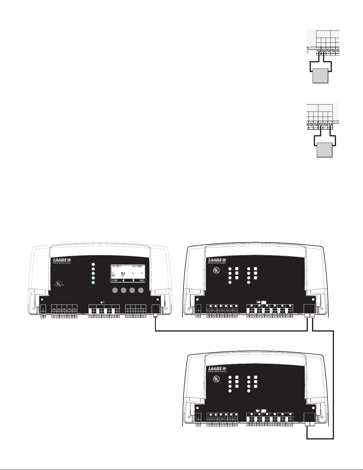
WIRING TO MODULATING MOTORS
7
V
WIRING TO 4-20MA MODULATING MOTORS (A TERMINALS 13, 14), (B TERMINALS 16, 17), ...
• The M4 can be equipped to operate up to four 4-20 mA modulating motors.
• The M4-Extension can be equipped to operate up to six 4-20 mA modulating motors.
• The M4 and the M4-Extension sources 24VDC excitation voltage for the 4-20mA signal.
• Wire the (-) from the modulating motor to the boiler terminal on the M4 marked (GND). That is for boiler A,
-
the modulating (-) terminal will be 13.
• Wire the (+) from the modulating motor to the boiler terminal on the M4 marked (mA). That is for boiler A,
o
M
the modulating (-) terminal will be 14.
C
R / VLT
D
WIRING THE VOLTAGE MODULATING MOTORS (A TERMINALS 13, 15), (B TERMINALS 16, 18),...
m
• The M4 Extension can be equipped to operate up to six 0-5V, 0-10V, 1-5V, or 2-10V modulating motors.
• Wire the (GND) from the modulating motor to the boiler terminal on the M4 marked (GND). That is for boiler
D, the modulating (GND) terminal will be 22.
• Wire the (V+) from the modulating motor to the boiler terminal on the M4 marked (VLT+). That is for boiler
D, the modulating (V+) terminal will be 23.
GN
CONNECTING TO THE M4-EXTENSION PANELS
• The M4 is equipped with a 6-pin phone socket to connect to extension panels.
• The M4-Extension is equipped with two 6-pin phone sockets to connect to M4 and an additional M4-Extension panel.
• Only 6-wire phone cable must be used for proper operation.
• Connection cable is provided as part of the M4-Extension package.
• Phone cables must be of a 6-wire with 6-pin terminals. Phone cables can extend up to 100'.
Boi
du
A
+
Modu
D
Page 11LAARS Modulating Controls M4 & M4-EXT
CUR / VLT
GND
-
13
14
-20mA
4
Burner
Motor
ler 4-2
lation Ou
U
C
T
D
N
VL
G
-
+
222021
oltage
V
B
Motor
oiler
B
lation
A
mA
+
0mA
D
R / VLT
m
m
23
urner
V
B
R/
CU
mA
VLT
GND
-
+
+
15
16
1
+
ut
p
t
T
A
A
VL
+
+
+
24
V+
ge
olta
ut
p
t
u
O
M4 Module
M4
SYSTEM
SYSTEM
A
A
B
B
C
C
D
D
A
A
CUR / VLTBCUR / VLTCCUR / VLT
CUR / VLT
CUR / VLT
CUR / VLT
GND
mA
VLT
GND
GND
mA
VLT
GND
-
-
-
-
+
+
+
+
16
13
15
14
13
16
15
14
B
mA
VLT
mA
VLT
+
+
+
+
18
17
18
17
RUNPROGRAM
RUNPROGRAM
CUR / VLTCCUR / VLT
mA
GND
mA
GND
-
-
+
+
20
19
20
19
PWR
PWR
L
L
1
1
N
N
2
2
OUTPUT RATINGS:
OUTPUT RATINGS:
120VAC, 6A RESISTIVE
120VAC, 6A RESISTIVE
1A PILOT DUTY, 15A TOTAL
1A PILOT DUTY, 15A TOTAL
FOR ALL CIRCUITS
FOR ALL CIRCUITS
INPUT RATINGS:
INPUT RATINGS:
115VAC 60Hz , 30VA MAX
115VAC 60Hz , 30VA MAX
USE COPPER WIRE,
USE COPPER WIRE,
CLASS 1 WIRE ONLY.
CLASS 1 WIRE ONLY.
ENCLOSED
ENCLOSED
ENERGY
ENERGY
MANAGEMENT
MANAGEMENT
EQUIPMENT
EQUIPMENT
LISTED
LISTED
99RA
99RA
A
SYS
A
SYS
5
7
6
3
4
5
7
6
3
4
CAUTION: RISK OF ELECTRIC SHOCK
CAUTION: RISK OF ELECTRIC SHOCK
More than one disconnect switch may be required
More than one disconnect switch may be required
to de-energize the equipment before servicing.
to de-energize the equipment before servicing.
C
B
D
C
D
B
10
9
8
12
11
9
10
8
12
11
Connecting M4 to
Two M4-Extension
Panels using RS485
FULL MODULATION SEQUENCING
Full Modulation Sequencing Control
---
DO NOT APPLY ANY VOLTAGE
DO NOT APPLY ANY VOLTAGE
TO INPUT TERMINALS
TO INPUT TERMINALS
PROVE
SYSTEM
OUTDOOR
PROVE
SYSTEM
OUTDOOR
D
D
mA
mA
VLT
VLT
GND
mA
VLT
VLT
mA
GND
-
-
+
+
+
+
+
+
+
+
23
24
21
22
23
22
24
21
/DHW
TEMP
TEMP
/DHW
TEMP
TEMP
O
T
T
O
O
O
O
O
T
T
30
26
28
25
29
27
30
28
25
26
29
27
---
SHUTDOWN
SHUTDOWN
/SETBACK
/SETBACK
31
31
M4-Extension A
M4-Ext
FULL MODULATION SEQUENCING EXTENSION
K
CUS
ENCLOSED
ENERGY
MANAGEMENT
EQUIPMENT
LISTED
99RA
EXTENSION
EXTENSION
MODULE
MODULE
RS-485
RS-485
O
O
32
32
PWR
LN
12E34F56G78H910
L
K
E
M
G
O
I
Comm
P
N
O
M
J
I
11 12
11 12
L
F
N
H
J
P
Power
Ext A
K
EFGH
CUR / VLT
CUR / VLT
GND
VLTmA
GND
13
1514
16
OUTPUT RATINGS:
120VAC, 6A RESISTIVE
1A PILOT DUTY, 15A TOTAL
FOR ALL CIRCUITS
INPUT RATINGS:
115VAC 60Hz, 12VA MAX
Use Copper Conductors Only.
CAUTION:
Risk of Electric Shock.
More than one disconnect switch may be required
to de-energize the equipment before servicing.
Ext B
N
L
M
CUR / VLT
CUR / VLT
GND
GND
VLTmAGND
VLTmAGND
VLTmAGND
GND
19
25
242322
212019
181716
22
O
IJ
CUR / VLT
CUR / VLT
VLTmA
GND
2726
28
EXTENSION
P
MODULE
VLTmAGND
RS-485
302916
M4-Extension B
M4-Ext
CUS
ENCLOSED
ENERGY
MANAGEMENT
EQUIPMENT
LISTED
99RA
M
K
PWR
LN
12E34F56G78H910
FULL MODULATION SEQUENCING EXTENSION
K
E
M
G
O
I
Comm
P
N
OL
J
I
11 12
11 12
L
F
N
H
J
P
Power
Ext A
K
EFGH
CUR / VLT
CUR / VLT
GND
VLTmA
GND
13
1514
16
OUTPUT RATINGS:
120VAC, 6A RESISTIVE
1A PILOT DUTY, 15A TOTAL
FOR ALL CIRCUITS
INPUT RATINGS:
115VAC 60Hz, 12VA MAX
Use Copper Conductors Only.
CAUTION:
Risk of Electric Shock.
More than one disconnect switch may be required
to de-energize the equipment before servicing.
Ext B
N
ML
CUR / VLT
CUR / VLT
CUR / VLT
GND
GND
VLTmAGND
VLTmAGND
VLTmAGND
GND
19
25
242322
212019
181716
22
O P
IJ
CUR / VLT
VLTmA
VLTmAGND
GND
302916
2726
28
EXTENSION
MODULE
RS-485
Page 12
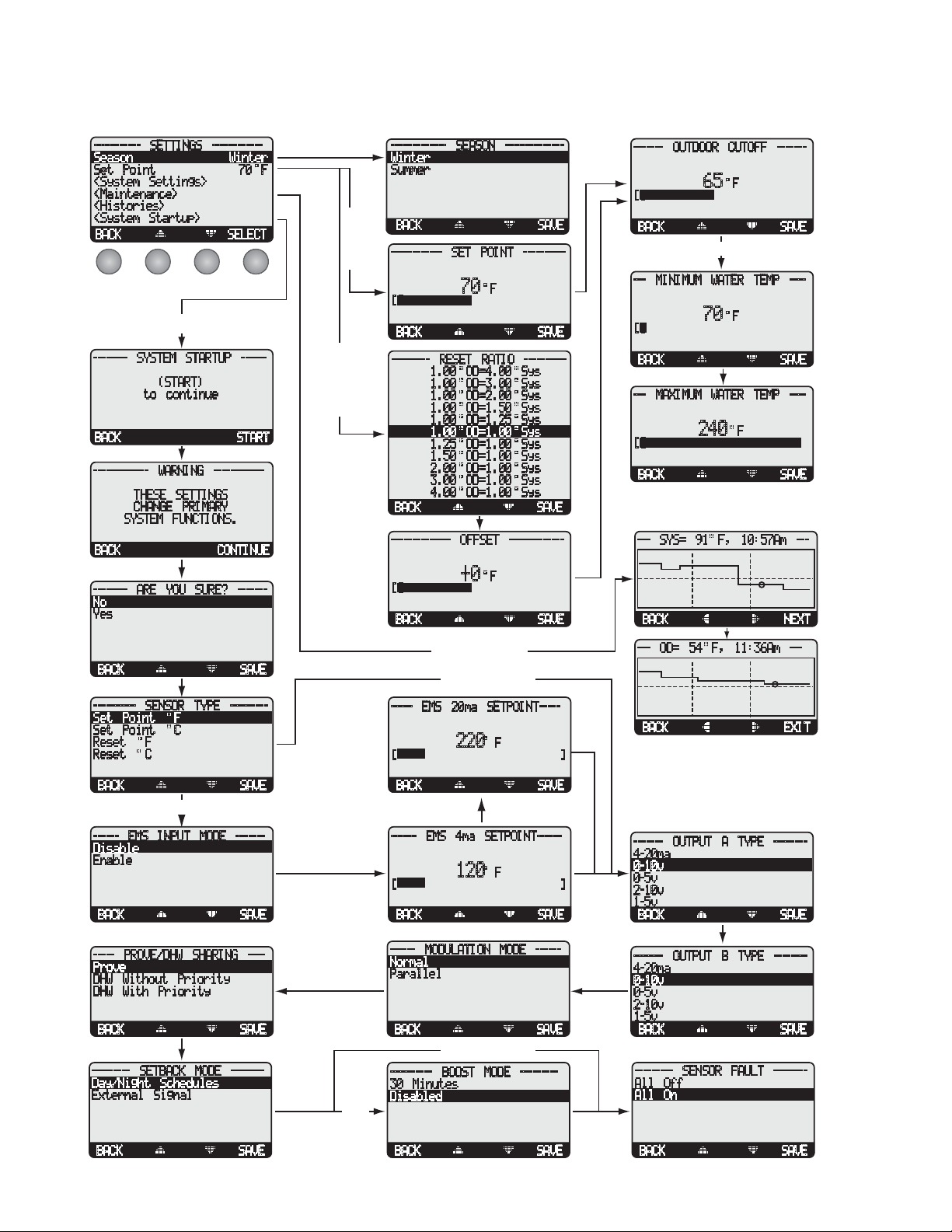
Page 12 LAARS Heating Systems
MENU SEQUENCE
----------- SETTINGS ------------
Season
Set Point
<System Settings>
<Maintenance>
<Histories>
<System Startup>
BACK
Winter
70 F
SELECT
-------- SYSTEM STARTUP ------
(START)
to continue
BACK
------------- WARNING ------------
THESE SETTINGS
CHANGE PRIMARY
SYSTEM FUNCTIONS.
BACK
-------- ARE YOU SURE? -------
No
Yes
START
CONTINUE
------------- SEASON --------------
Winter
Summer
BACK
------------ SET POINT ----------
F
[]
BACK
--------- RESET RATIO ----------
1.00 OD=4.00 Sys
1.00 OD=3.00 Sys
1.00 OD=2.00 Sys
1.00 OD=1.50 Sys
1.00 OD=1.25 Sys
1.00 OD=1.00 Sys
1.25 OD=1.00 Sys
1.50 OD=1.00 Sys
2.00 OD=1.00 Sys
3.00 OD=1.00 Sys
4.00 OD=1.00 Sys
BACK
-------------- OFFSET -------------
[]
BACK
70
+0
F
SAVE
SAVE
SAVE
SAVE
------- OUTDOOR CUTOFF -------
F
[]
BACK
--- MINIMUM WATER TEMP ----
[]
BACK
--- MAXIMUM WATER TEMP ----
[]
BACK
--- SYS= 91 F, 10:57Am ---
BACK
65
F
70
F
240
SAVE
SAVE
SAVE
NEXT
BACK
---------- SENSOR TYPE ---------
Set Point F
Set Point C
Reset F
Reset C
BACK
Set Point
------ EMS INPUT MODE -------
Disable
Enable
BACK SAVE
----- PROVE/DHW SHARING ----
Prove
DHW Without Priority
DHW With Priority
BACK SAVE
--------- SETBACK MODE --------
Day/Night Schedules
External Signal
SAVE
SAVE
Reset Options
----- EMS 20ma SETPOINT-----
F
[]
BACK
------ EMS 4ma SETPOINT------
[]
BACK
------ MODULATION MODE ------
Normal
Parallel
BACK
---------- BOOST MODE ---------
30 Minutes
Disabled
220
F
120
SAVE
SAVE
SAVE
--- OD= 54 F, 11:36Am ---
BACK
------- OUTPUT A TYPE -------4-20ma
0-10v
0-5v
2-10v
1-5v
BACK
------- OUTPUT B TYPE -------4-20ma
0-10v
0-5v
2-10v
1-5v
BACK
--------- SENSOR FAULT --------
All Off
All On
EXIT
SAVE
SAVE
BACK SAVE
BACK SAVE
BACK SAVE
Page 13
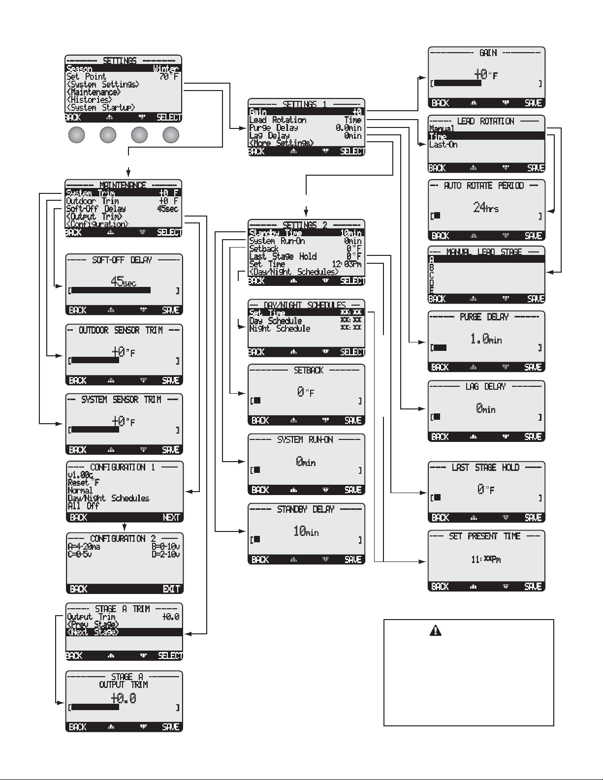
----------- SETTINGS ------------
Season Winter
Set Point 70 F
<System Settings>
<Maintenance>
<Histories>
<System Startup>
BACK SELECT
MAINTENANCE
SYSTEM SETTINGS1
---------- SETTINGS 1 ----------
Gain +0
Lead Rotation Time
Purge Delay 0.0min
Lag Delay 0min
<More Settings>
BACK SELECT
Page 13LAARS Modulating Controls M4 & M4-EXT
---------------- GAIN --------------
F
[]
BACK SAVE
-------- LEAD ROTATION -------
Manual
Time
Last-On
BACK SAVE
+0
---------- MAINTENANCE ---------
System Trim +0 F
Outdoor Trim +0 F
Soft-Off Delay 45sec
<Output Trim>
<Configuration>
BACK SELECT
------- SOFT-OFF DELAY --------
sec
[]
BACK SAVE
-- OUTDOOR SENSOR TRIM ----
[]
BACK SAVE
--- SYSTEM SENSOR TRIM ----
[]
BACK SAVE
------ CONFIGURATION 1 ------
v1.00c
Reset F
Normal
Day/Night Schedules
All Off
BACK NEXT
------ CONFIGURATION 2 -----A=4-20ma B=0-10v
C=0-5v D=2-10v
45
+0
+0
F
F
SYSTEM SETTINGS2
---------- SETTINGS 2 ----------
Standby Time 10min
System Run-On 0min
Setback 0 F
Last Stage Hold 0 F
Set Time 12:03Pm
<Day/Night Schedules>
BACK SELECT
--- DAY/NIGHT SCHEDULES ---
Set Time **:**
Schedule
Day Schedule **:**
Night Schedule **:**
BACK SELECT
-------------- SETBACK -----------
F
[]
BACK SAVE
-------- SYSTEM RUN-ON --------
[]
BACK SAVE
-------- STANDBY DELAY --------
[]
BACK SAVE
0
0
10
min
min
EXTERNAL SETBACK
--- AUTO ROTATE PERIOD ---
hrs
[]
BACK SAVE
---- MANUAL LEAD STAGE ----
A
B
C
D
E
BACK SAVE
--------- PURGE DELAY ---------
[]
BACK SAVE
----------- LAG DELAY -----------
[]
BACK SAVE
------ LAST STAGE HOLD ------
[]
BACK SAVE
----- SET PRESENT TIME -----
24
min
1.0
min
0
F
0
11:**Pm
BACK EXIT
-------- STAGE A TRIM -------Output Trim +0.0
<Prev Stage>
<Next Stage>
BACK SELECT
-------------- STAGE A -----------
[]
BACK SAVE
OUTPUT TRIM
+0.0
BACK SAVE
CAUTION
To be able to change the M4
settings the Program/Run Switch
must be set to Program. The switch
is located under the Enclosure
Wiring Cover for security. The
Enclosure Wiring Cover can be
securely closed using a lock.
Page 14
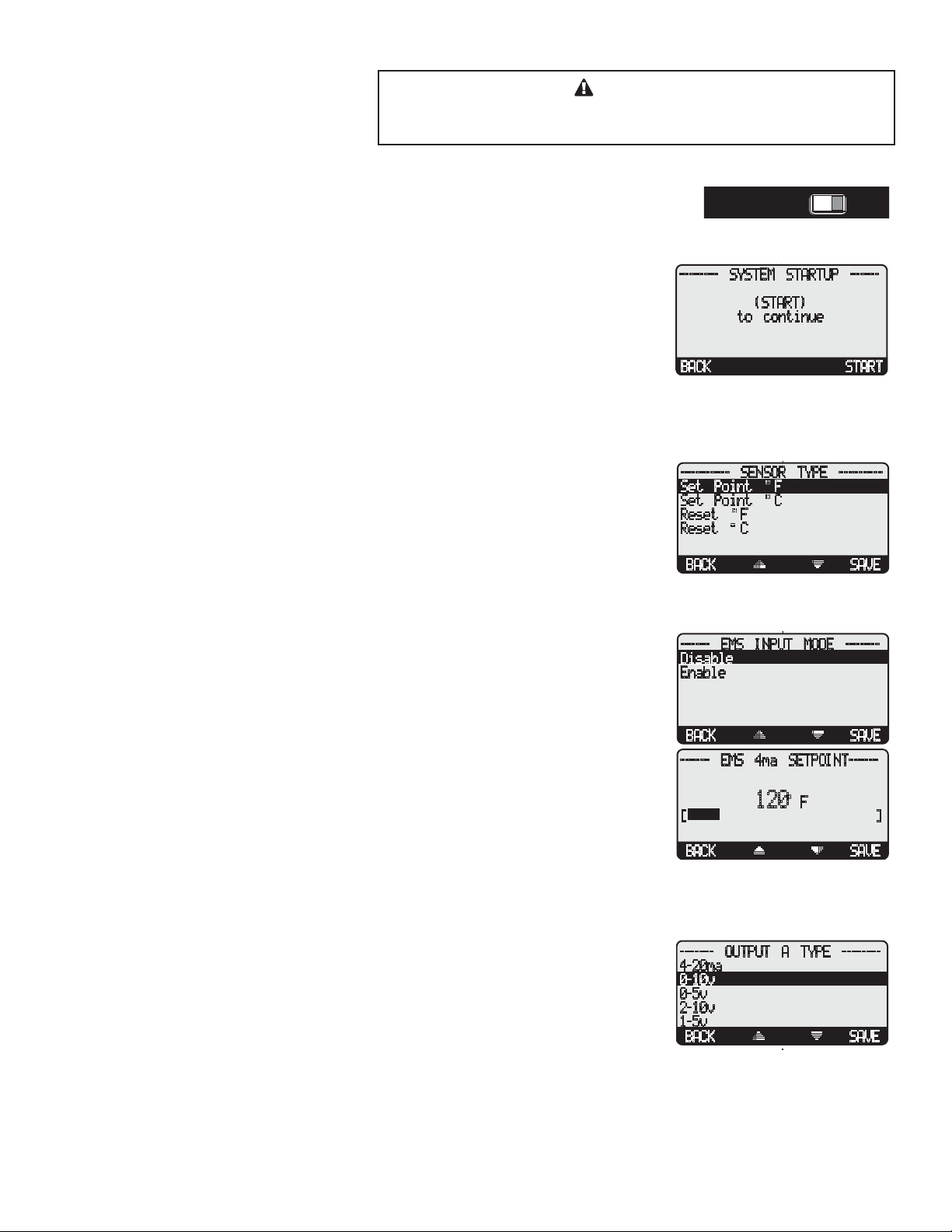
Page 14 LAARS Heating Systems
STARTUP SETTINGS
A good practice after performing any Startup menu modifications is to
CAUTION
check all operating settings and adjustments to match the new settings.
PROGRAM CHANGE SETTINGS
To be able to change the M4 settings the Program/Run Switch must be set to Program. The
switch is located under the Enclosure Wiring Cover for security. The Enclosure Wiring Cover
can be securely closed using a lock.
STARTUP SEQUENCE
Button: MENU/<System Startup>
• When powered, the M4 performs a self-test on its components.
• After the self-test diagnostics have been successfully completed, the M4 will initialize
the panel.
• On the first power up, the System Startup screen will appear after the initialization is
complete. If it doesn’t, the M4 has already been configured.
• The System Startup menu sets the main parameters like the type of sensor, the type of
output, and the modulating mode.
SENSOR TYPE
Set Point °F, Set Point °C, Reset °F, Reset °C Default: Set Point ºF
Button: MENU/<System Startup>/..../Sensor type
• Reset mode is only available if an outdoor sensor is connected to terminals 25 and 26.
DO NOT select Reset without an outdoor sensor.
• The same LAARS temperature sensor can display in either °F or °C.
• If °F is selected, all temperatures and settings will be displayed in degrees Fahrenheit and
the M4 will operate as a Set Point Control in degrees Fahrenheit.
• If °C is selected, all temperatures and settings will be displayed in degrees Celsius and
the M4 will operate as a Set Point Control in degrees Celsius.
• Set point mode does not require an outdoor sensor. If an outdoor sensor is connected in
Set Point mode it will be used only as an outdoor cutoff point. That is, to turn the boilers
and system pump off.
RUNPROGRAM
RUNPROGRAM
-------- SYSTEM STARTUP ------
(START)
to continue
BACK START
---------- SENSOR TYPE ---------
Set Point F
Set Point C
Reset F
Reset C
BACK SAVE
------ EMS INPUT MODE -------
Disable
Enable
EMS INPUT MODE (AVAILABLE IN SET POINT ONLY)
Disable, Enable Default: Disable
Button: MENU/<System Startup>/..../EMS Input Mode
• This allows the M4 to receive an external set point from an EMS/BMS system.
• You must select the 4mA (min) and 20 mA (max) Set Points in the following screen.
• The 4mA can be set to any temperature between 70ºF to 200ºF.
• The 20mA can be set to any temperature between 90ºF to 240ºF. However, the minimum
must be 20ºF higher than the 4mA setting.
• Connect the 4-20mA EMS Control Interface to the M4 RS485 connection.
SELECTING THE OUTPUT TYPE
4-20mA, 0-5V, 0-10V, 1-5V, or 2-10V Outputs Default: 4-20mA
Button: MENU/<System Startup>/..../Output A type/Output B type
• Outputs can be configured for 4-20mA operation (current) or the voltage range can be
selected (0-5V, 0-10V, 1-5V, 2-10V).
• Check the modulating motor to determine its control requirements.
• Select the appropriate Output Type for each of the boilers. The M4 can have a different
Output type for each boiler.
BACK SAVE
------ EMS 4ma SETPOINT------
120 F
[]
BACK SAVE
------- OUTPUT A TYPE -------4-20ma
0-10v
0-5v
2-10v
1-5v
BACK SAVE
Page 15
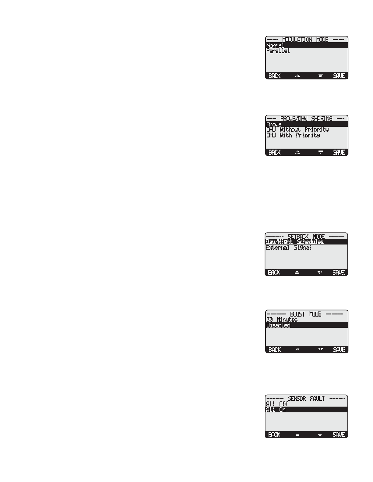
Page 15LAARS Modulating Controls M4 & M4-EXT
SELECTING THE MODULATING MODE
Normal, Parallel Default: Normal
Button: MENU/<System Startup>/..../Modulating Mode
------ MODULATION MODE ------
Normal
Parallel
• Some boilers run more efficiently as their modulation increases. For these units, it is
more energy efficient to run one unit in high than several units at lower modulation. If
your units are of this type, select Normal. This is the recommended setting for typical
BACK SAVE
steel and cast iron boilers.
• There are some units that run more efficiently at lower modulation. If it is more energy
efficient to run several units at lower modulation than one at high, select Parallel. This is
typically used on copper boilers, low mass boilers, or burners with high turndown ratios.
PROVE/DOMESTIC HOT WATER (DHW)
Prove, DHW Without Priority, DHW With Priority Default: Prove
Button: MENU/<System Startup>/..../Prove-DHW Sharing
----- PROVE/DHW SHARING ----
Prove
DHW Without Priority
DHW With Priority
• Input Terminals 29 and 30 can be used with either of the above features.
• When Prove is selected, the M4 will not start any boiler stage unless Prove terminals are
BACK SAVE
connected.
• Using those terminals to connect to an aquastat for a Domestic Hot Water call and selecting either of the DHW options will
raise the calculated water temperature to the lower of 200°F or Max Water Temperature.
• Domestic hot water without priority allows the SYS relay, mostly controlling a primary system pump, to remain energized
during a domestic hot water call (aquastat call on terminals 29 and 30). In Summer or when outdoor temperature is above
Outdoor Cutoff, a DHW call will energize the SYS relay. After the DHW call termination, the SYS relay will continue to run
for the System Run-On period before turning off.
• However, domestic hot water with priority de-energizes the SYS relay during a domestic hot water call (aquastat call on
terminals 29 and 30) for a period of one hour. If after the hour period the DHW call still exist, the SYS relay will energize and
the M4 will continue in the higher temperature setting until the domestic hot water call has terminated.
--------- SETBACK MODE --------
SETBACK MODE
Day/Night Schedules, External Signal Default: Day/Night Schedules
Day/Night Schedules
External Signal
Button: MENU/<System Startup>/..../Setback Mode
• The M4 has two levels of heat, a normal/day and a setback/night. The Normal is good
for when buildings are occupied and people are active. The Setback/Night holds a lower
BACK SAVE
system temperature and is for when buildings are unoccupied or inactive.
• The Day/Night Schedules provides the user with a Day Time setting for Normal operation and a Night Time setting for Setback.
• The External Signal option switches the M4 to Setback mode when an external signal is received through the Setback terminals.
This allows the M4 to be managed by an external device or control to provide setback.
---------- BOOST MODE ---------
BOOST MODE
30 Minutes, Disabled Default: 30 Minutes
30 Minutes
Disabled
Button: MENU/<System Startup>/..../Boost Mode
• If you do not want a Boost simply select Disabled from the Boost Menu.
• Boost is only available if Day/Night Schedules is selected as a Setback option.
BACK SAVE
• The morning Boost is designed to return the building to comfortable ambient temperatures after the cooler Night (Setback)
period. The M4 will accomplish this by running elevated water temperatures (will add Setback setting to calculated water
temperature) for 30 minutes before the start of the Day schedule setting. That is, if the normal day set point at a specific outdoor
was 145˚F and the Setback setting was 20˚F, the boost will raise the system calculated temperature to 165˚F for 30 minutes
before the start of the Day Schedule setting.
--------- SENSOR FAULT --------
SENSOR FAULT
All Off, All On Default: All On
All Off
All On
Button: MENU/<System Startup>/..../Sensor Fault
The Sensor Fault will determine the operating status of all output stages that are set to Auto
when a sensor reads Short or Open.
BACK SAVE
Page 16
Page 16 LAARS Heating Systems
RESET MODE
• When All-On is selected, the M4 will turn all boilers On to a 100% when System reads Short or Open and Outdoor is below
Outdoor Cutoff. When Outdoor reads Short or Open, the M4 will turn all boilers On to a 100%.
• When All-Off is selected, the M4 will turn all boilers Off when either System or Outdoor sensor reads Short or Open.
SET POINT MODE
• When All-On is selected, the M4 will turn all boilers On to a 100% when the System sensor reads Short or Open.
• When All-Off is selected, the M4 will turn all boilers Off when the System sensor reads Short or Open.
• The Outdoor Sensor Short or Open status will not affect the control operation in Set Point mode.
OPERATING SETTINGS
PROGRAM CHANGE SETTINGS
To be able to change the M4 settings the Program/Run Switch must be set to Program. The
switch is located under the Enclosure Wiring Cover for security. The Enclosure Wiring Cover
can be securely closed using a lock.
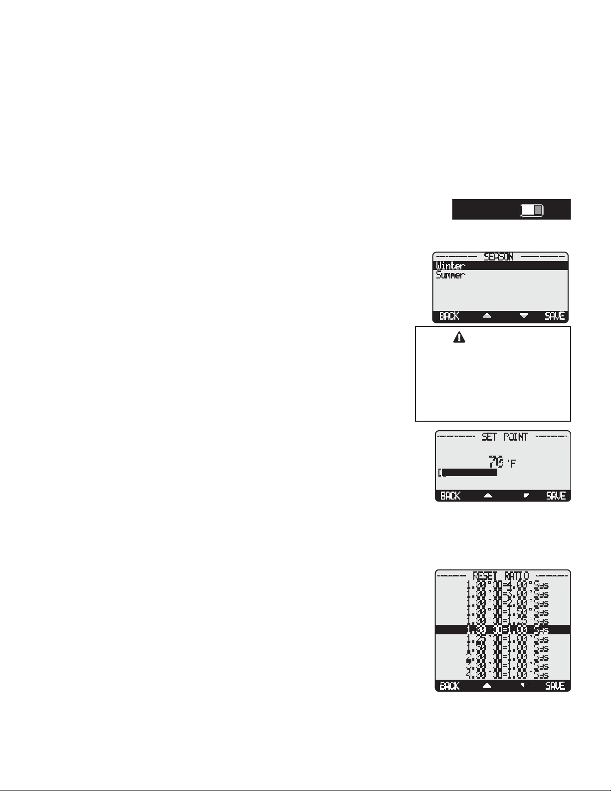
SEASON
Winter, Summer Default: Winter
Button: MENU/Season
• The M4 will turn all boiler relays off when it is in Summer setting. However, a DHW
call will bring boilers back on if needed. The Message Display Line will display Summer
to show status.
• When in Winter, the M4 will activate the Sys relay whenever the Outdoor temperature
(OD) falls to or below the Outdoor Cutoff setting. In addition, it will begin heating
whenever the System temperature (SYS) falls below the Set Point Temperature. The
Message Display Line will not display any season information when in Winter.
• When the heating season is over, it is a good practice to switch the M4 to Summer
setting. This will allow DHW calls to operate the boilers when needed.
SET POINT
Adjustable 70ºF - 250ºF Default: 70ºF
Button: MENU/Set Point
• The Set point is the temperature value the M4 will use to control the system.
• The M4 will increase, decrease or hold the modulation of the boilers to maintain the
system temperature around the Set point.
• The system can be expected to fluctuate around the set point. The amount of fluctuation
depends on the Modulation Mode, System Settings, and Stage Settings.
• If the EMS Mode was Enabled, the Set Point will be set by the EMS/BMS system and
will be available to be read but not changed on the display.
RUNPROGRAM
RUNPROGRAM
------------- SEASON --------------
Winter
Summer
BACK SAVE
CAUTION
DO NOT turn power off to the
M4 when heating season is
over. If you do so, the battery
will run down and will have to
be replaced. Instead switch to
Summer.
------------ SET POINT ----------
70 F
[]
BACK SAVE
RESET RATIO
Adjustable 1.00ºOD : 4.00ºSys to 4.00ºOD : 1.00ºSys Default: 1.00ºOD : 1.00ºSys
Button: MENU/Set Point
• The Reset Ratio determines how the System water temperature (SYS) will vary with
Outside temperature (OD). With any of the ratios, the colder it becomes outside,
the hotter the temperature of the system water. The ratios are adjustable from 1.00
(OD):4.00 (SYS) to 4.00 (OD):1.00 (SYS). (See Understanding Operation Concept on
page 5)
• With a 1.00 (OD):4.00 (SYS) ratio, the System water temperature (SYS) will increase
rapidly as the outside temperature falls, hitting the maximum of 240°F at 24°F outside
temperature. With a 4.00 (OD):1.00 (SYS) ratio, the System water temperature (SYS)
will increase slowly as the outside temperature falls. Even at -30°F, the system water
will only be 125°F, and at 24°F outside, the system water will be 112°F. Such a low
Reset Ratio might be used with radiant floor heating applications.
--------- RESET RATIO ----------
1.00 OD=4.00 Sys
1.00 OD=3.00 Sys
1.00 OD=2.00 Sys
1.00 OD=1.50 Sys
1.00 OD=1.25 Sys
1.00 OD=1.00 Sys
1.25 OD=1.00 Sys
1.50 OD=1.00 Sys
2.00 OD=1.00 Sys
3.00 OD=1.00 Sys
4.00 OD=1.00 Sys
BACK SAVE
Page 17
• With most baseboard heating applications, a 1.00 (OD):1.00 (SYS) setting is a good
place to start. With a 1.00 (OD):1.00 (SYS) ratio, for every degree the outside
temperature falls, the system water temperature is increased one degree.
• If required: Adjust the RESET RATIO in cold weather. If the ambient building
temperatures are too cold in cold weather, move the ratio to a higher selection. That is,
if 1.00 (OD):1.00 (SYS) was initially selected, change the selection to 1.00 (OD):1.25
(SYS). If the building temperatures are too warm in cold weather, move the ratio to
a lower selection. That is, if 1.00 (OD):1.00 (SYS) was initially selected, change the
selection to 1.25 (OD):1.00 (SYS).
130
120
110
Water Temperature
100
70 405060
Outdoor Temperature
Page 17LAARS Modulating Controls M4 & M4-EXT
1:4 1:1
Warmer
Colder
4:1
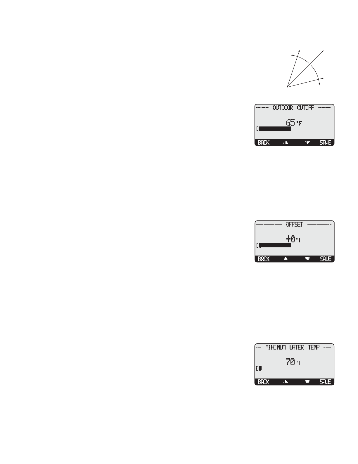
OUTDOOR CUTOFF TEMPERATURE
------- OUTDOOR CUTOFF -------
Adjustable Off, 20ºF - 100ºF, On Default: 65ºF
Button: MENU/Set Point/Outdoor Cutoff in Set Point
Button: MENU/Set Point/Offset/Outdoor Cutoff in Reset
[]
65 F
• If the outdoor sensor is installed, the Outdoor Cutoff screen will automatically appear
after the temperature Set Point has been selected.
BACK SAVE
• When the outdoor temperature falls to the adjustable Outdoor Cutoff temperature, the M4
will control and modulate Boilers to hold the calculated temperature.
• When the outdoor temperature rises to the Outdoor Cutoff plus a 2°F differential, the M4 will turn all boilers off. The System
relay will remain energized for the Run-On delay then de-energize. The Message Display Line will display Outdoor Cutoff.
• The Outdoor Cutoff can be set from 20°F to 100°F. In addition, the Setting can be set to ON or OFF. In the ON position, the
System Relay will run regardless of the Outdoor temperature (OD) and the burner stages will be active to hold the calculated
water temperature. (Note: The lowest water temperature the M4 will circulate is 70°F. If the Outdoor Cutoff is turned ON and
the Season is set to Winter, the M4 will circulate at least 70°F water even in the hottest of weather.) In the OFF position, the
system pump will always be off and all burner stages will be off.
OFFSET
-------------- OFFSET -------------
Adjustable 50ºF - (-50ºF) Default: 0ºF
Button: MENU/Set Point/Offset in Reset only
• The Offset setting lets you adjust the starting points of the Reset Ratio curves. This
[]
+0 F
means that, regardless of the Outdoor temperature (OD), or the Reset Ratio that has
been selected, when the Offset setting is changed, that change is directly added to or
BACK SAVE
subtracted from the calculated temperature. For example, if the Set Point temperature
was 130°F and the Offset was changed from 0° to 10° (an increase of 10°), then the Set
Point temperature would increase to 140°F
• The Offset setting does not change the ratio selection. For instance, with 1.00 (OD):1.00 (SYS) Reset Ratio, the System water
temperature (SYS) will always increase one degree for each degree change in the Outdoor temperature (OD). What the Offset
does is add or subtract a constant temperature value. (See Understanding Operation Concept)
• If required: Adjust the Water Offset in mild weather. If the ambient building temperatures are too warm in the mild weather,
decrease the Water Offset. If the ambient building temperatures are too cold in the mild weather, increase the Water Offset. The
rule of thumb for baseboard radiation is to change the Offset 4°F for every 1°F you wish to change the building temperatures.
In radiant heat applications, change the Offset 1°F or 2°F for every 1°F you wish to change the building temperature.
MINIMUM WATER TEMP
Adjustable 70ºF - 180ºF Default: 70ºF
Button: MENU/Set Point/Offset/Outdoor Cutoff/Minimum Water Temp in Reset only
• The Minimum Water Temperature must be set to the boiler manufacturer’s specification.
The M4 will calculate the Set Point based on the Outdoor temperature (OD), the Reset
Ratio, and the Offset value. The M4 will control all boilers modulation to hold either the
Set Point temperature, or the Minimum Water Temperature, whichever is higher.
• The Minimum Water Temperature must be at least 20°F lower than the Maximum
Temperature (See next setting).
--- MINIMUM WATER TEMP ----
70 F
[]
BACK SAVE
Page 18
Page 18 LAARS Heating Systems
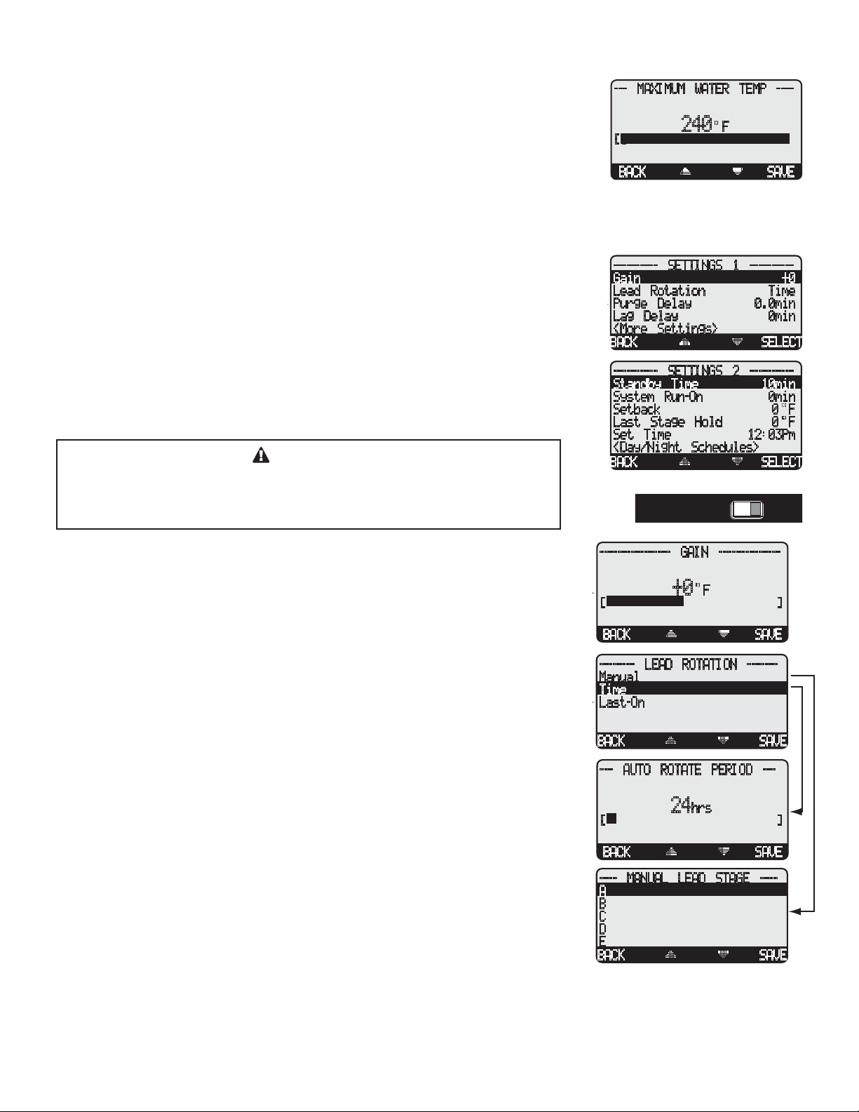
MAXIMUM WATER TEMP
Adjustable 90ºF - 240ºF Default: 240ºF
Button: MENU/Set Point/Offset/..../Maximum Water Temperature in Reset only
• This is the highest temperature heating water the M4 will circulate through the heating
system. It is available in Reset mode only.
• When using a radiation system, it should be set according to the tubing or floor
manufacturer’s specification.
• The Maximum Temperature must be at least 20°F higher than the Minimum Temperature.
SYSTEM SETTINGS
Button: MENU/<System Settings>
The Settings 1 and Settings 2 menus provide access to adjusting and fine-tuning the system for
enhanced comfort and more fuel savings. The M4 behaves differently based on the selected
Control Modes (see Startup Settings).
• Gain
• Lead Rotation
• Purge Delay
• Lag Delay
• Standby Time
CAUTION
To be able to change the M4 settings the Program/Run Switch must be set to
Program. The switch is located under the Enclosure Wiring Cover for security.
The Enclosure Wiring Cover can be securely closed using a lock.
• System Run-On
• Setback
• Last Stage Hold
• Day/Night Schedules
--- MAXIMUM WATER TEMP ----
240 F
[]
BACK SAVE
---------- SETTINGS 1 ----------
Gain +0
Lead Rotation Time
Purge Delay 0.0min
Lag Delay 0min
<More Settings>
BACK SELECT
---------- SETTINGS 2 ----------
Standby Time 10min
System Run-On 0min
Setback 0 F
Last Stage Hold 0 F
Set Time 12:03Pm
<Day/Night Schedules>
BACK SELECT
RUNPROGRAM
RUNPROGRAM
GAIN
Adjustable -10 to +10 Default: 0
Button: MENU/<System Settings>/Gain
• The Gain adjusts the aggressiveness of the M4 PID logic to control how much
modulation is changed when the system temperature is different from the Set Point.
• A Gain of 0 is a good starting point for all systems.
• If during normal load conditions, the system temperature tends to fluctuate significantly,
decrease the Gain by two numbers (for example, from 0 to -2). Wait for at least 15
minutes before evaluating how the change has affected the system.
• If, during normal load conditions the system temperature tends to remain consistently
below the Set Point (or consistently above the Set Point), increase the Gain by two
numbers (for example, from 0 to 2). Wait for at least 15 minutes before evaluating how
the change has affected the system.
LEAD BOILER ROTATION
Adjustable Manual, Time (1 hr to 60 Days), Last-On Default: Time (24Hours)
Button: MENU/<System Settings>/Lead Rotation
• The Lead Boiler is the first boiler brought on when output is required.
• The Lead Boiler can be rotated automatically, manually or based on Last-On. The
automatic rotation is recommended.
• The current Lead Boiler is shown in brackets on the main display.
• Only Boilers which are set to Auto Mode can be Lead. Therefore, not all the Boilers may
be available when manually selecting a new Lead Boiler.
---------------- GAIN --------------
+0
24
F
hrs
[]
BACK SAVE
-------- LEAD ROTATION -------
Manual
Time
Last-On
BACK SAVE
--- AUTO ROTATE PERIOD ---
[]
BACK SAVE
---- MANUAL LEAD STAGE ----
A
B
C
D
E
BACK SAVE
Page 19
Page 19LAARS Modulating Controls M4 & M4-EXT
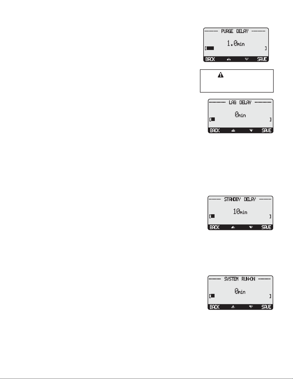
PURGE DELAY
Adjustable 0.0min to 10.0min Default: 1.0min
Button: MENU/<System Settings>/Purge Delay
• Many boilers go through a purge cycle before they are brought on line.
• When the M4 activates a boiler, it does not start to calculate its output until the Purge
Delay is over. This allows the boiler to fully come on line and begin producing output.
• The Purge Delay helps to prevent short cycling of a newly activated burner. Once the
burner is activated, it MUST run through the entire Purge Delay period.
• The minimum Purge Delay setting MUST be set to the time required by the boiler
manufacturer. Time entry is in 0.1 of a minute (i.e. 1.5min will equal 90 seconds.)
• The Message Display Line will display Purge Delay and the amount of time remaining
in the purge.
LAG DELAY
Adjustable 0min to 60min Default: 0min
Button: MENU/<System Settings>/Lag Delay
• The Lag Delay requires the previous stage to remain at 100% modulation for the full
period of the Lag Delay before another Stage can be activated. For example, if the Lag
Delay was set to 10 minutes, the Lead Stage would need to remain at 100% modulation
for a full ten minutes (never backing down to even 99%) before a lag stage could be
activated. The Message Display Line will display Lag Delay and the remaining time.
• Set the Lag Delay to 0 min when two or more Stages will generally be needed to hold the load.
• The Lag Delay is useful in installations where one unit should usually have enough output to hold the load unless it fails or load
conditions become extreme.
• The Lag Delay overrides the value of the Modulation Point selected for each stage. Regardless of that setting, the previous stage
must reach 100% and stay there before another Stage can be activated.
• The full Lag Delay must always elapse regardless of what happens to system temperature. Therefore, set the Lag Delay to 0 min
if you want smooth set point control using multiple units.
--------- PURGE DELAY ---------
min
[]
BACK SAVE
1.0
CAUTION
Set Purge Delay as per boiler
manufacturer recommendation.
----------- LAG DELAY -----------
min
[]
BACK SAVE
0
STANDBY TIME
Adjustable 1min to 60min Default: 10min
Button: MENU/<System Settings>/<More Settings>/Standby Time
• The Standby Delay Time only applies to Boilers in Standby Mode.
• A boiler can be set to be a Standby boiler using the Stage Menu.
• A Standby Boiler can only be activated after all the boilers in Auto Mode have run at
100% modulation for the full Standby Time.
• Standby boilers are used for backup or extreme load conditions only. A Standby Boiler
can never be a Lead Stage
• The full Standby Delay Time must always elapse regardless of what happens to system temperature. Therefore, shorter Standby
Times will result in smoother set point operation in extreme conditions. Longer Standby Times may prevent a Standby Boiler
from firing if the other boilers can eventually meet the load, or if the load decreases.
SYSTEM RUN-ON
Adjustable 0min to 360min Default: 0min
Button: MENU/<System Settings>/<More Settings>/System run-On
• The SYS relay will energize whenever the Outdoor temperature (OD) is below the
Outdoor Cutoff. When the Outdoor temperature increases 2°F above the Outdoor Cutoff
after the last burner relay has de-energized, the SYS relay will stay on for a period set
by the System Run-On. This allows the Pump to dissipate the residual heat within the
boilers back into the system.
• A common use for the System Run-On is to control a system pump in a heating system. The extra time helps transfer the heat
from the boilers to the heating system.
• The System Run-On time should be set based on the size and type of the boilers and pumps. In general, a boiler with low
water content and high horsepower will need a longer System Run-On than a boiler with the same horsepower and more water
content. (Refer to boiler manufacturer recommendation)
-------- STANDBY DELAY --------
min
[]
BACK SAVE
-------- SYSTEM RUN-ON --------
[]
BACK SAVE
10
0
min
Page 20
Page 20 LAARS Heating Systems
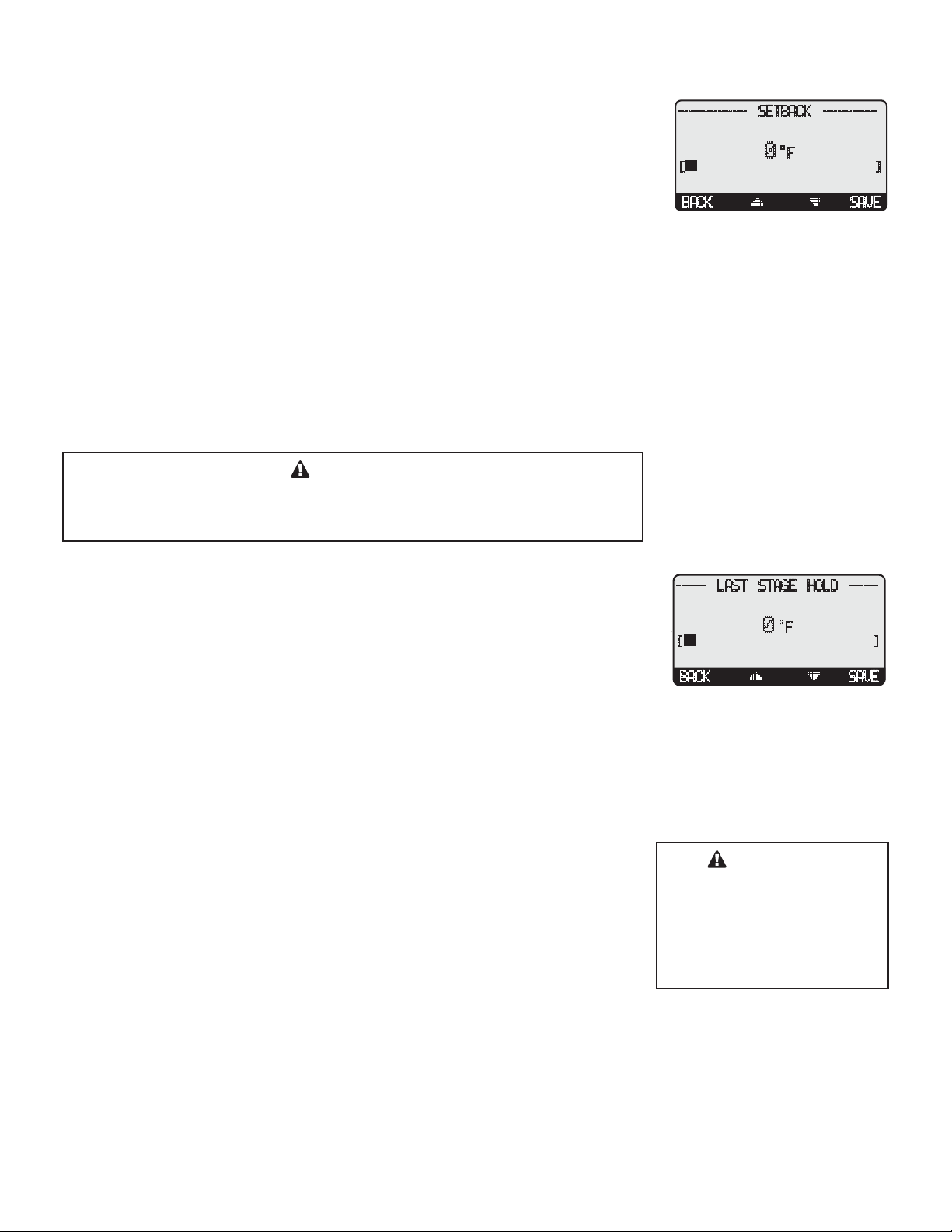
SETBACK
Adjustable 0°F to 75°F Default: 0°F
Button: MENU/<System Settings>/<More Settings>/Setback
• The Setback feature can be used to provide the M4 with a lower temperature Set Point
when less load is required.
• The lower Set Point will appear on the main display indicating this condition.
• For an example, if the calculated temperature is 180°F and the Setback is 20°F, then
when in Setback, the M4 will hold a Set Point of 160°F.
• A typical use for Setback is to provide less system temperature to a building during the
night or on the weekends when building is not occupied, but heat is still required.
• The amount of Setback selected is subtracted from the Set Point when a Setback External Signal is received or the Night Time
schedule setting started.
• If External Signal is selected as a Setback Mode (See Startup menu), the Setback will not be activated unless a dry contact
signal source is wired into the Shutdown/Setback terminals (31 and 32) and the M4 receives a SHORT signal.
• If Day/Night Schedules is selected as a Setback Mode (See Startup menu), the Setback will be activated only when Night
Schedule time has started.
-------------- SETBACK -----------
F
[]
BACK SAVE
0
CAUTION
When using Soft-Off and Last Stage Hold, the last boiler stage will not turn off
until both parameters have elapsed. In this case, Soft-Off will start after the Last
Stage Hold.
LAST STAGE HOLD
Adjustable 0°F to 30°F Default: 0°F
Button: MENU/<System Settings>/<More Settings>/Last Stg Hold
• The Last Stage Hold prevents short cycling of the Lead Stage during low load periods.
• In low load conditions, the system might require only 5% of the output of one Stage.
When the M4 brings on the Lead Stage, the Set Point is quickly exceeded, and the M4
turns the Lead Stage off.
• To prolong the run time during this type of condition, use the Last Stage Hold setting.
• The M4 will let the system temperature exceed the Set Point by the number of degrees
selected, before the Lead Stage is turned off.
• For example, with a Set Point of 160°F and a Last Stage Hold setting of 10°F, the Lead
Stage boiler will remain on, at low modulation, until the Set Point reaches 170°F.
• From an efficiency standpoint, it is better to overshoot slightly than to short cycle a
boiler.
Avoiding Conflicting Boiler Limits
• The temperature limits set on the boilers MUST be set considerably higher than the M4’s
Set Point for the reasons detailed below.
• The M4 sensor is located in a common header some distance from the boilers.
• As the temperature rises in the header and before reaching the sensor location, energy is
dissipated. Therefore, the temperature in the header could be lower than that registered
by boiler sensors.
• In addition to the normal drop experienced between the boiler’s temperature and that
read by the M4 sensor, the Last Stage Hold setting must be accounted for. The boiler limit must be set above the Set Point
PLUS the Last Stage Hold PLUS the normal drop experienced in the piping.
• Using the previous example of a 10°F Last Stage Hold with a 160°F Set Point, the boilers’ limits must be set enough over 170°F
to prevent the boilers’ internal limits being reached. In this situation, the boiler high limit should be set at approximately 180°F
to prevent the difference in boiler temperature vs. header temperature causing erratic operation.
------ LAST STAGE HOLD ------
F
[]
BACK SAVE
0
WARNING
The temperature limits set
on the boilers must be higher
than the M4 Set Point. Read
the section at left for details
that will prevent erratic system
operation.
Page 21
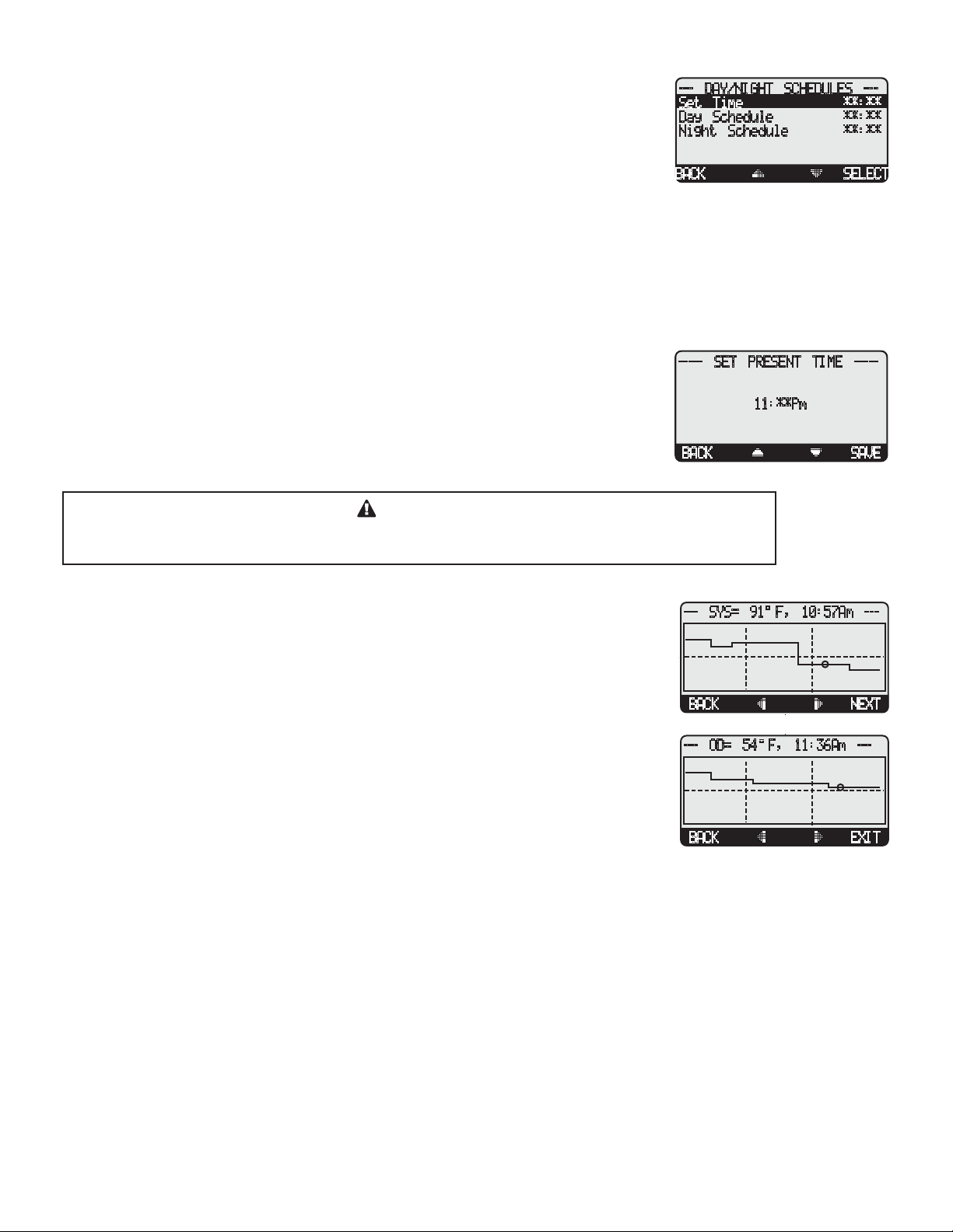
Page 21LAARS Modulating Controls M4 & M4-EXT
DAY/NIGHT SCHEDULES
(Available when "Day/Night Schedules" is selected from the Setback Startup
menu option only)
Button: MENU/<System Settings>/<More Settings>/Day/Night Schedules
• The M4 has two levels of heat. The Day level is used when a building is occupied and
people are active.
• The Night (Setback) level is used when a building is not occupied, or when people are
sleeping. This setting reduces the calculated temperature by the Setback setting. If
the Day calculated water temperature was 150˚F and the Setback was 20˚F, the Night
Schedule will run at (150˚F - 20˚F) = 130˚F.
• If the Boost feature is being used, it uses the Day Schedule as a Boost ending point. That is, if the Day Schedule is set to start
at 6:00AM, the Boost will start 30 minutes prior to the Day setting at 5:30AM. The M4 will then raise the calculated water
temperature by the Setback amount. Using the previous example, at 5:30AM the M4 will raise the calculated water to 170˚F
(150˚F + 20˚F) until 6:00AM.
--- DAY/NIGHT SCHEDULES ---
Set Time **:**
Day Schedule **:**
Night Schedule **:**
BACK SELECT
----- SET PRESENT TIME -----
SET TIME
Button: MENU/<System Settings>/<More Settings>/Set Time
Button: MENU/<System Settings>/<More Settings>/<Day/Night Schedules>/Set Time
• Adjust the time by selecting Time from the menu and then scrolling through the hours
followed by the minutes. If hours are to be set to PM, scroll through the AM hours to
reach the PM hours.
BACK SAVE
11:**Pm
CAUTION
Remember that the battery is the backup for the Time. If no power is supplied to the M4 and there
was no battery or battery had no power, time values will be lost and will need to be reset.
HISTORY
Button: MENU/<Histories>
The M4 provides users with a graphical history of the System and Outdoor temperatures for
the previous 24 hours. The temperatures are sampled every 12 minutes. That is, readings of
both System and Outdoor temperatures are recorded and stored every 12 minutes for the last
24 hours.
• To view the values of specific time period, use the two middle buttons to scroll to that
time and read the upper left temperature.
• The first screen will be the System Temperature History. By clicking on the Next button,
you'll be able to view the Outdoor Temperature History.
--- SYS= 91 F, 10:57Am ---
BACK
--- OD= 54 F, 11:36Am ---
BACK
NEXT
EXIT
Page 22
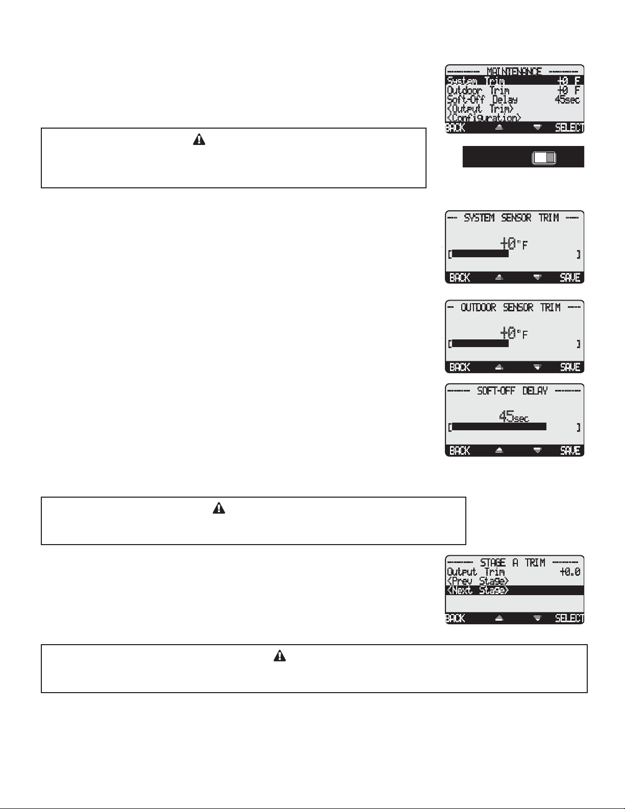
Page 22 LAARS Heating Systems
T
T
MAINTENANCE
Button: MENU/<Maintenance>
The Maintenance menu gives access to sensor and outputs trimming and Soft-Off. In
addition, you'll have access to view the Startup configuration settings.
CAUTION
To be able to change the M4 settings the Program/Run Switch must be set to
Program. The switch is located under the Enclosure Wiring Cover for security.
The Enclosure Wiring Cover can be securely closed using a lock.
SYSTEM & OUTDOOR SENSOR TRIM
Adjustable -5°F to +5°F Default: 0°F
Button: MENU/<Maintenance>/System Trim
Button: MENU/<Maintenance>/Outdoor Trim
• The LAARS thermistor type sensors are very accurate, and normally require no
calibration. Sometimes it may be desirable to make small adjustments to the displayed
value for either the Outdoor temperature (OD) or the System temperature (SYS). The
Trim setting can adjust the displayed value by ± 5°F.
• Do not use the Trim setting to make the Outdoor temperature sensor match that reported
on the radio or TV. Outdoor temperature can vary widely over a broadcast range. Only
trim the outdoor sensor based on an accurate thermometer reading taken where the
sensor is located.
---------- MAINTENANCE ---------
System Trim +0 F
Outdoor Trim +0 F
Soft-Off Delay 45sec
<Output Trim>
<Configuration>
BACK SELEC
RUNPROGRAM
RUNPROGRAM
--- SYSTEM SENSOR TRIM ----
F
[]
BACK SAVE
-- OUTDOOR SENSOR TRIM ----
[]
BACK SAVE
+0
+0
F
SOFT-OFF DELAY
Adjustable 0sec to 60sec Default: 45sec
Button: MENU/<Maintenance>/Soft-Off Delay
• When a stage is no longer needed, the Soft-Off keeps that stage burner in Low Fire prior
to turning it off.
• The display will show a percent that is equal to the Ignition % for the stage in Soft-Off
delay. That number will blink for the Soft-Off delay period.
• If during the Soft-Off stage delay period the M4 needed that stage to turn back on, the
stage will be released from the Soft-Off delay and resume normal operation.
------- SOFT-OFF DELAY --------
sec
[]
BACK SAVE
45
CAUTION
When using Soft-Off and Last Stage Hold, the last boiler stage will not turn off until both
parameters have elapsed. In this case, Soft-Off will start after the Last Stage Hold.
OUTPUT TRIM
Adjustable -5 to +5 Default: 0
Button: MENU/<Maintenance>/Output Trim
• Each of the stages controlled by the M4 has a separate Output Trim setting.
• Output Trim acts as an adjustment to a stage output percent to match the burner motor.
• After adjusting the Output Trim, test the operation to make sure the results match your
expectation.
-------- STAGE A TRIM --------
Output Trim +0.0
<Prev Stage>
<Next Stage>
BACK SELEC
CAUTION
DO NOT use the Output Trim for a Stage unless it is absolutely necessary. Test burner operation and modulation
output matching after adjusting the Output Trim.
Page 23
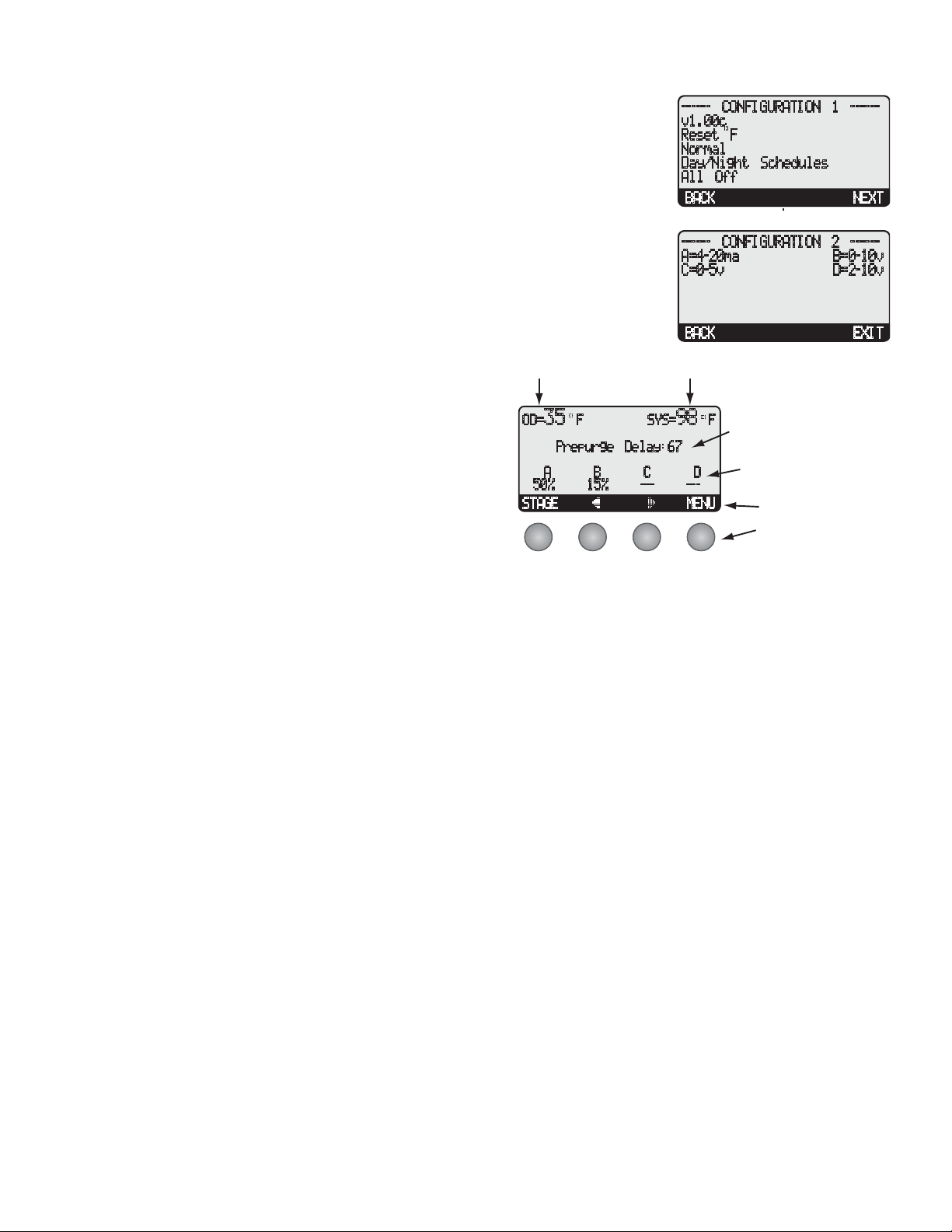
CONFIGURATION
Button: MENU/<Maintenance>/<Configuration>
• This menu option provides a consolidated view of the Startup settings the M4 has been
set to.
• Additional stage settings will be available by selecting the NEXT option.
Page 23LAARS Modulating Controls M4 & M4-EXT
------ CONFIGURATION 1 -----v1.00c
Reset F
Normal
Day/Night Schedules
All Off
BACK NEXT
------ CONFIGURATION 2 ------
A=4-20ma B=0-10v
C=0-5v D=2-10v
BACK EXIT
DISPLAY
The M4 display layout provides a variety of information that
gives an immediate picture of the operation status. The display
shows four boilers at a time. The two middle buttons scrolls the
screen to view additional boilers. Moreover, all the information
is brightly displayed. It can be viewed in brightly or dimly lit
rooms.
• The buttons' functionality changes based on the screen and
menu level your in. The buttons' functionality are displayed
on a dark background on the screen bottom line.
F
5
=
3
D
O
g
r
u
p
e
Pr
A
0
5
AG
T
S
B
5
1
%
E
S
7
6
:
y
a
l
e
D
e
- -
D
-
E
M
-
U
N
C
-
-
%
F
8
9
=
S
Y
• Horizontal arrows are to scroll through the available stages.
• Vertical arrows are to scroll through the menu functions
when in menus or to change values of settings when in its
specific screen.
DISPLAY BOILER MODULATION STATUS
The M4 boiler modulation status gives immediate access to each boiler status. The following list show all possible boiler status:
• --- Boiler is off due to no call for heat.
• 97% Boiler is modulating at the indicated percentage.
• ON Boiler Stage Mode is set to ON and boiler is firing at 100% (boiler is in bypass).
• OFF Boiler Stage Mode is set to OFF and boiler stage is unavailable or boiler does not exist.
• m95% Boiler Stage Mode is set to Manual and set to the specified percent.
• C/E Boiler on Extension panel is communicating back to the M4..
DISPLAY MESSAGES
The M4 normal display layout reserved the second line for message indications. The following is a list of the most common
Message Display Line information:
• Summer The control is set to Summer. No heat is active.
• Shutdown Active The Shutdown Terminals are Shorted. No boilers will be active.
• Shutdown by EMS The EMS is below 2mA or above 22mA
• DHW Call (171˚F) There is a DHW (Domestic Hot Water) call. The M4 will Raise system Set Point to the indicated
temperature. DHW increases calculated temperature to 200˚F or Max Water Temperature, whichever
is lower.
• Purge Delay: 23 The current boiler is in purge cycle and the remaining purge time in seconds is 23.
• Holding Until 150˚F The Lead boiler is in Last Stage Hold. This example shows that the lead stage will turn off when
system temperature reaches 150˚F.
• System Run-On: 46 The System relay is ON for the System Run-On Delay. This example shows that it will remain in
System Run-On for an additional 46 seconds before turning off.
• Waiting for Prove The System relay is ON and the prove terminals are open before the lead boiler relay can energize.
• Prove Failure After boilers have run for a while, Prove signal was opened. The boiler relays will de-energize.
However, the System relay will remain energized.
Page 24
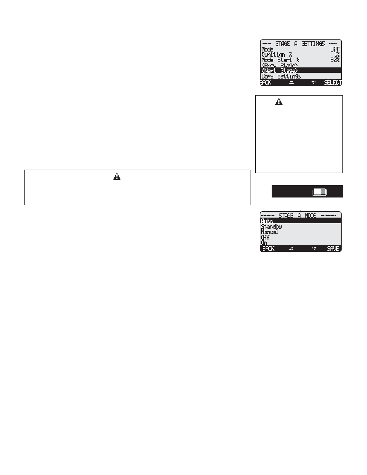
Page 24 LAARS Heating Systems
BOILER STAGE SETTINGS
Button: STAGE/
The Maintenance menu gives access to sensor and outputs trimming and Soft-Off. In
addition, you'll have access to view the Startup configuration settings.
• In most installations, all active boiler adjustments are the same, but each can be
configured differently if desired.
• If the Boilers are not set up properly, the M4 operation may appear to be erratic.
• When the STAGE button is depressed, the Boiler A Settings menu will be shown.
• Make all the appropriate settings for Boiler A (See below).
• After completing all the settings for Boiler A (See below), you have the option of
copying these settings to all other Boilers. Everything but the Mode -- Auto/Standby/
Manual/Off/On -- will be copied.
• Then select the Next Stage option from the menu to bring up the Boiler B Settings menu
and make all the settings. Continue until all boilers have been set.
• If a M4-Extension is connected to the M4, scrolling through stages using the Next and
Prev Stage menu options will scroll through the M4-Extension stages as well.
----- STAGE A SETTINGS ----
Mode Off
Ignition % 1%
Mode Start % 80%
<Prev Stage>
<Next Stage>
Copy Settings
BACK SELECT
CAUTION
Remember to set the Mode
for each stage. For Stages
that do not have a boiler,
contractor must change their
Mode to OFF. Otherwise the
M4 will include them in the
modulation calculation and
rotation. That might have dire
effects on system response.
CAUTION
To be able to change the M4 settings, the Program/Run Switch must be set to
RUNPROGRAM
Program. The switch is located under the Enclosure Wiring Cover for security.
The Enclosure Wiring Cover can be securely closed using a lock.
MODE
Auto, Standby, Manual, Off, On Default: Auto
Button: STAGE/Mode
• The M4 only controls the modulation of boilers set to Auto or (after a delay) those set
to Standby. None of the other settings is recommended for output boilers connected to
active units.
• Any boiler without an active unit connected must be set to Off.
• The following list describes the MODE options:
Auto - The M4 will control the boiler’s operation to maintain the desired Set Point. Only Boilers set to Auto can be Lead boilers.
------- STAGE A MODE --------
Auto
Standby
Manual
Off
On
BACK SAVE
RUNPROGRAM
Standby Standby boilers can only be activated when all boilers in Auto have been at 100% modulation for a selectable period of
time. Standby is generally used when you want a specific boiler to be available in extreme load conditions. Note that a
Standby boiler Cannot be a Lead boiler.
Manual The Manual Mode should only be used when testing a boiler. Manual overrides the Prove input. The exact percent of
modulation for a boiler can be set with the Manual mode. Once selected, the unit will immediately turn on and modulate to
the selected percentage.
Off Any output Boiler A through D not connected to a physical unit should be set to Off. The Off Mode can also be used to
disable units that are being serviced.
On The On Mode should only be used when testing a boiler. The On Mode overrides the PROVE input. Once set to On the
boiler will immediately start firing and modulate to 100%.
Page 25
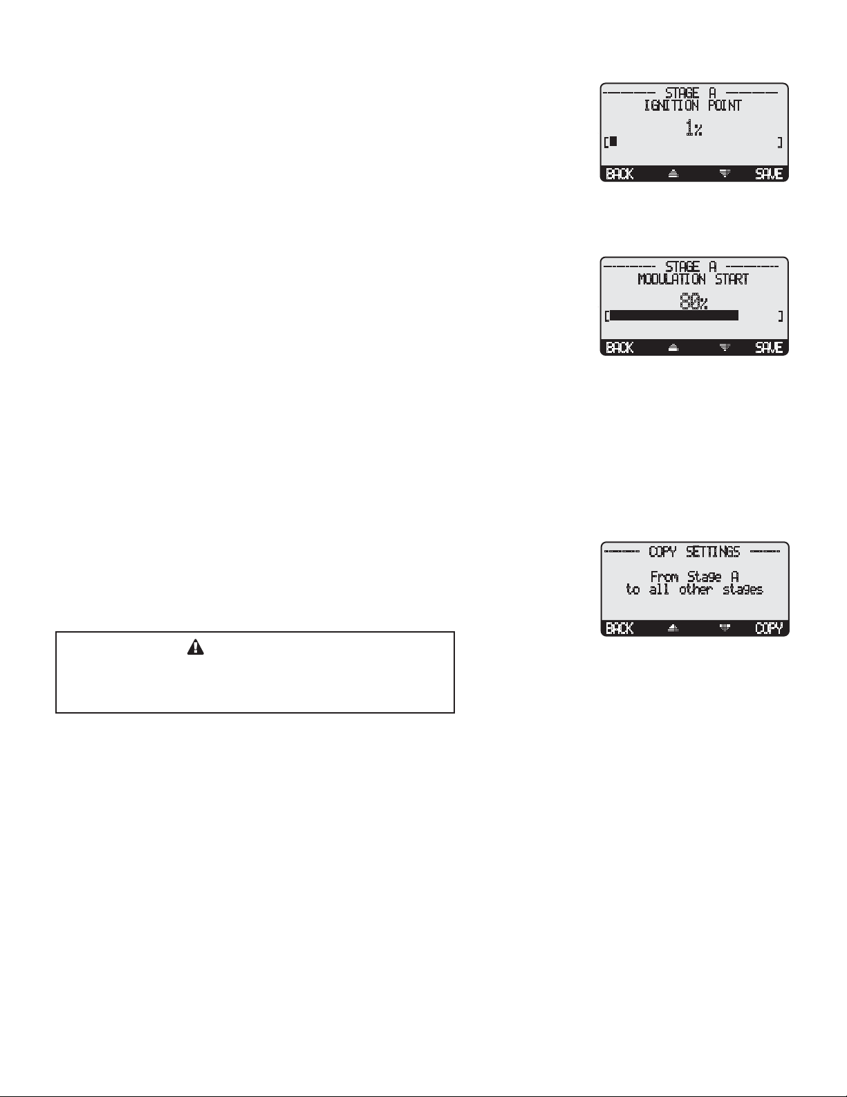
Page 25LAARS Modulating Controls M4 & M4-EXT
IGNITION %
Adjustable 1% to 50% Default: 1%
Button: STAGE/Ignition %
• The Ignition Point is the percent of modulation that must be attained before the unit can
be activated.
• For most modern power draft units, the Ignition Point should be set at 1%.
• Older units or atmospheric units may require the modulating fuel valve to be open from
20-50% before proper ignition can be attained. Check with the boiler manufacturer if
you are in doubt about the minimum position of the fuel valve for ignition.
MODULATION START %
Adjustable 0% to 100% Default: 80%
Button: STAGE/Mod Start %
• The Modulation Start determines at what modulation percent the previous boiler should
be for the current boiler to be activated.
• For example, if the Modulation Start for Boiler B is set to 75%, then when Boiler A
reaches 75% modulation, Boiler B (if Boiler B is in Auto Mode and is not already on)
will be brought on in low fire.
• When modulation is decreasing, the lag unit will remain on in low modulation, until the previous boiler reaches 40% of its
Modulation Start point, or 2% above the Ignition Point, whichever is higher.
• Using the same example, as the load decreases, Boiler B would modulate down to low. Boiler A would then modulate down to
30%. Only then would Boiler B turn off.
• If the Lag Delay is set to anything other than 0, a boiler must always go up to 100% modulation before the next boiler is
activated. However, the Modulation Start should still be set correctly, because it will be valid when modulation is decreasing.
• The Modulation Start point will generally be set differently based on the Modulating Mode selected.
------------ STAGE A -----------IGNITION POINT
1%
[]
BACK SAVE
------------ STAGE A ------------
MODULATION START
80%
[]
BACK SAVE
COPY SETTINGS - BOILER A ONLY
Button: STAGE/Copy Settings
• If all the active boilers will have the same Ignition Start Point and Modulation Point,
they can be set for Boiler A and then copied to the other boilers.
• It is still required to select the Mode for all other boilers. The Mode will not be copied.
IMPORTANT
The Mode MUST be set for each boiler. The Copy Settings
command will not set the Mode for Boilers B, C, and D. Only
Ignition % and Modulation Start % are copied.
-------- COPY SETTINGS -------
From Stage A
to all other stages
BACK COPY
Page 26
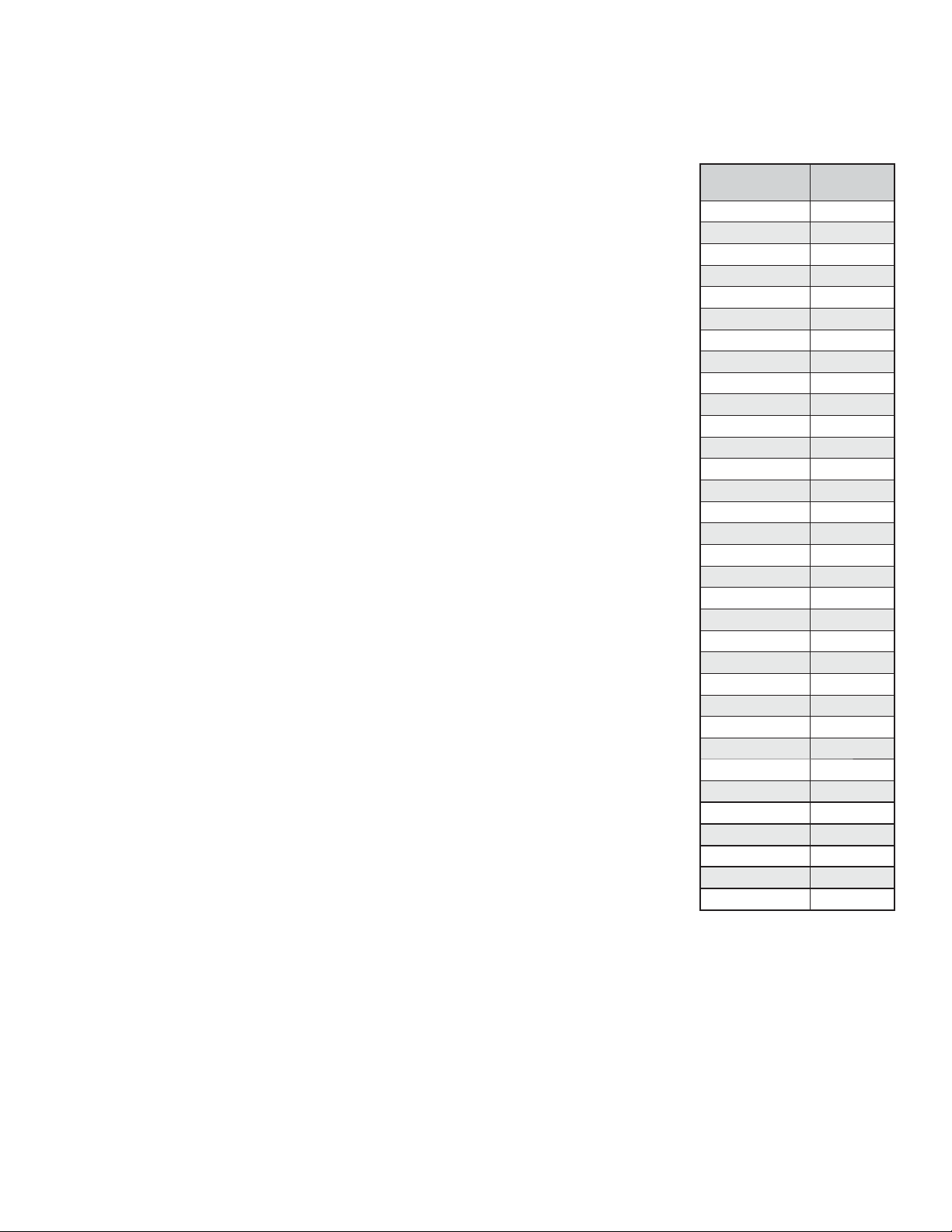
Page 26 LAARS Heating Systems
TROUBLESHOOTING
TEMPERATURE INPUTS
Display shows Sensor OPEN
Check the sensor is connected and the wires are continuous to the M4. Finally follow the
procedure for Incorrect Temperature Display.
Display shows Sensor SHORT
The M4 sees a short across the input terminals. Remove the wires from either the SYSTEM
TEMP or OUT TEMP terminals (whichever is reading SHORT). The display should change to
read OPEN. If it doesn’t, the M4 may be damaged.
Display shows an Incorrect Temperature Display
Remove the wires from either the SYSTEM TEMP or OUT TEMP terminals (whichever is
reading incorrectly). The display should change to read OPEN. If it doesn’t, the M4 may be
damaged. Take an ohm reading across the detached sensor wires. The ohm reading should
correspond to the side chart. If it doesn’t, the sensor may be damaged.
CONTROL OPERATION
No Heat
• (Check Diagram on next page)
Too Much Heat
Check if the control has any of the following:
• Domestic Hot Water call - The M4 will raise the temperature of the system to either 200˚F or
Maximum Water Temperature on a DHW call, connected to terminals 29 and 30. Check to see
if there is a call for DHW and the length of time it lasts.
• Reset Ratio and Offset - If excessive heat occurs only in certain weather, adjust the Reset
Ratio and Offset (See Understanding Operating Concept). If excessive heat occurs year round,
reduce the Offset.
• Boiler Mode Settings - The M4 will only modulate boilers their mode is set to Auto or
Standby. Check to if any boiler stage is set to Manual or On.
• Control Settings - The Last Stage Hold will allow only the Lead boiler to stay on for an
additional number of degrees. If the setting is too high, and only the Lead boiler is on, the
system can over heat. Reduce the Last Stage Hold setting.
Too Little Heat
Check if the control has any of the following:
• Reset Ratio and Offset - If reduced heat occurs only in certain weather, adjust the Reset
Ratio and Offset (See Understanding Operating Concept). If reduced heat occurs year round,
increase the Offset.
Temperature Sensor Chart
TEMPERATURE
(in Degrees °F)
-30 117720
-20 82823
-10 59076
0 42683
10 31215
20 23089
25 19939
30 17264
35 14985
40 13040
45 11374
50 9944
55 8714
60 7653
70 5941
80 4649
90 3667
100 2914
110 2332
120 1879
130 1524
140 1243
150 1021
160 842
170 699
180 583
190 489
200 412
210 349
220 297
230 253
240 217
250 187
Value
(in Ohms)
• Setback and Day/Night Schedule - If reduced heat occurs only during specific hours, check
the Day/Night Schedule and the Setback values. Either reduce the Setback setting or change
the Day and Night Schedules.
• Boiler Mode Settings - The M4 will only modulate boilers their mode is set to Auto or Standby. Check to if any boiler stage is
set to Manual, Off, or Standby.
Boilers are Short-Cycling
• Lag Delay - Increase the Lag Delay only if all boilers tend to short-cycle.
• Last Stage Hold - Increase the Last Stage Hold only if the lead boiler tends to short-cycle.
System is Overshooting or Undershooting
• Gain - If the system is overshooting reduce the Gain.
• Gain - If the system is undershooting increase the Gain.
Page 27
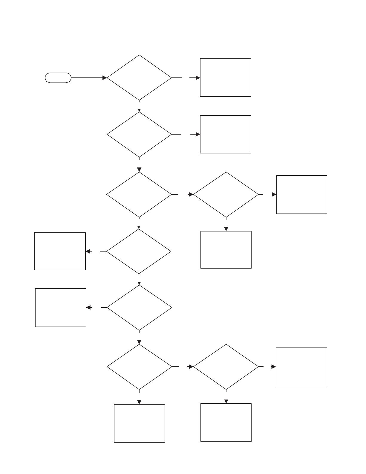
TROUBLESHOOT - NO HEAT
Page 27LAARS Modulating Controls M4 & M4-EXT
START
The control is in DHW
Priority and is
providing all output to
domestic water.
NO
Does the control have
power?
YES
Is the control in
SUMMER mode?
NO
Is the SYSTEM
Relay AND any of the
Boiler Output Relay
lights ON?
NO
Is the SYSTEM Relay
light ON?
NO
YES
YES
Turn control power
ON.
Select WINTER from
the Season menu.
Does the
Output relays that are
ON have continuity?
NO
Contact Factory for
control troubleshoot.
YES
Check the wiring
from control to the
boilers and the
pump.
Check plumbing for
heat distribution.
Check SHUTDOWN or
PROVE signal source.
YES
YES
Is the control
display indicates a
SHUTDOWN or PROVE
status?
NO
Is any of the
System or Outdoor
Sensors Short or Open?
YES
Replace the faulty
sensor.
NO
Is the Outdoor
sensor reading above
the Outdoor Cutoff
setting?
YES
Either change the
Outdoor Cutoff setting
or wait for the
Outdoor temperature
to drop below that
setting.
Check control heat
NO
settings for proper
heating Reset Ratio or
Set Point.
Page 28

Page 28 LAARS Heating Systems
Specifications
Voltage Input: . . . . . . . . . . . . . . . . . . . . . . . . . . . . . . . . . . . . . . . . . . . . . . . . . 120 VAC 60 Hz
Power Consumption: . . . . . . . . . . . . . . . . . . . . . . . . . . . . . . . . . . . . . . . . . . . . . . . . 12 VA Max
Operating Temperature: . . . . . . . . . . . . . . . . . . . . . . . . . . . . . . . . . . . . . . . . . . . 20°F to 120°F
Operating Humidity: . . . . . . . . . . . . . . . . . . . . . . . . . . . . . . . . . . . . . . . . . . . . . . . 20% to 80%
Dimensions: . . . . . . . . . . . . . . . . . . . . . . . . . . . . . . . . . . . . . . . . . . . . . . . . 11"W x 9" H x 3 ¾" D
Weight: . . . . . . . . . . . . . . . . . . . . . . . . . . . . . . . . . . . . . . . . . . . . . . . . . . . . . . . . . 2.5 pounds
M4 Specifications
Lead Stage Rotation: . . . . . . . . . . . . . . . . . . . . . . . . . . Time ( 1 to 1440 Hours (60 days)), Manual, Last-On
Pump Output: . . . . . . . . . . . . . . . . . . . . . . . . . . . . . . . . . . . . . . . . . . . . . . . . . (1) N.O. S.P.S.T
Boiler Modes: . . . . . . . . . . . . . . . . . . . . . . . . . . . . . . . . . . . . . . . . . . Auto, Manual, Standby, On, Off
Standby Time: . . . . . . . . . . . . . . . . . . . . . . . . . . . . . . . . . . . . . . . . . . . . . . . . . . 1 to 60 minutes
Modulating Output Types: . . . . . . . . . . . . . . . . . . . . . . . . . . . . . (4) 4-20mA, 0-5V, 0-10V, 1-5V, 2-10V
Output Relay Ratings: . . . . . . . . . (5) 1 Amp inductive, 6Amp resistive at 120 VAC 60 Hz, 15A total for all circuits
Add-On M4-Extension Panels: . . . . . . . . . . . . . . . . . . . . . . . . . up two M4-Extension Panels using RS485
Ignition Point %: . . . . . . . . . . . . . . . . . . . . . . . . . . . . . . . . . . . . . . . . . . . . . . . . . . . 1 to 50%
Modulation Start Point %: . . . . . . . . . . . . . . . . . . . . . . . . . . . . . . . . . . . . . . . . . . . . 0 to 100%
Modulation Modes: . . . . . . . . . . . . . . . . . . . . . . . . . . . . . . . . . . . . . . . . . . . . . .Normal or Parallel
Temperature Display: . . . . . . . . . . . . . . . . . . . . . . . . . . . . . . . . . . . . . . . . . . Fahrenheit or Celsius.
Display: . . . . . . . . . . . . . . . . . . . . . . . . . . . . . . . . . . . . Graphical Alphanumeric (7 rows x 21 char. each)
LED: . . . . . . . . . . . . . . . . . . . . . . . . . . . . . . . . . . . . . . (1) System Output relay, (4) Boiler Output relays
Sensor Ranges: . . . . . . . . . . . . . . . . . . . . . . . . . . . . . . . Outdoor temperature sensor - minus 35°F to 250°F
Heating system sensor - minus 35°F to 250°F
Outdoor Cutoff Range: . . . . . . . . . . . . . . . . . . . . . . . . . . . . . . . 20°F to 100°F, ON and OFF
Reset Ratio Range: . . . . . . . . . . . . . . . . . . . . . . (1.00 : 4.00) to (4.00 : 1.00) (Outdoor : System Water)
Offset Adjustment: . . . . . . . . . . . . . . . . . . . . . . . . . . . . . . . . . . . . . . . . . . minus -40°F to plus 40°F
Minimum Water Temperature: . . . . . . . . . . . . . . . . . . . . . . . . . . . . . . . . . 70°F to 170°F
Maximum Water Temperature (Reset Only): . . . . . . . . . . . . . . . . . . . . . . . . . 90°F to 240°F
Set Point Temperature Range: . . . . . . . . . . . . . . . . . . . . . . . . . . . . . . . . . 70°F to 250°F
EMS Temperature Range: . . . . . . . . . . . . . . . . . . . . . . . . . . . . . . . . . . . 70°F to 240°F
Domestic Hot Water: . . . . . . . . . . . . . . . . . . . . . . . . . . . . . . . . . . . . . with Priority or without Priority
Pump Run-On: . . . . . . . . . . . . . . . . . . . . . . . . . . . . . . . . . . . . . . . . . . . . . . . . . 0 to 360 minutes
Purge Delay: . . . . . . . . . . . . . . . . . . . . . . . . . . . . . . . . . . . . . . . . . . . . . . . . 0.0 to 10.0 minutes
Lag Delay: . . . . . . . . . . . . . . . . . . . . . . . . . . . . . . . . . . . . . . . . . . . . . . . . . . . . 0 to 60 minutes
Last Stage Hold: . . . . . . . . . . . . . . . . . . . . . . . . . . . . . . . . . . . . . . . . . . . . . . . . . . . . 0 to 30°F
Schedules: . . . . . . . . . . . . . . . . . . . . . . . . . . . . . . . . . . . (1) Day and (1) Night (Setback) settings per day
Night Setback: . . . . . . . . . . . . . . . . . . . . . . . . . . . . . . . . . . . . . . . . . . . . . . . . . . . . 0°F to 75°F
Power Backup: . . . . . . Lithium coin battery, 100 days minimum 5 year replacement (Maintains Clock in power outages).
External Inputs: . . . . . . . . . . . . . . . . . . . . . . . . . . . . Shutdown Input, and Prove Input. (Dry Contacts Only)
Season: . . . . . . . . . . . . . . . . . . . . . . . . . . . . . . . . . . . . . . . . . . . . . . . . . . . . Winter and Summer.
M4-Extension Specifications
(Each M4-Extension can add up to (6) additional modulating boilers. A maximum of two M4-Extensions can be added to a
single M4.)
Extension Numbering: . . . . . . . . . . . . . . . . . . . . . . . . . . . . . . . . . . . . . . . . . . . . Toggle Switch A or B
Boiler Outputs: . . . . . . . . . . . . . . . . . . . . . . . . . . . . . . . . . . . . . . . . . . . . . . . . . . (6) N.O. S.P.S.T.
Modulating Output Types: . . . . . . . . . . . . . . . . . . . . . . . . . . . . . . . (6) 4-20mA, 0-5V, 0-10V, 1-5V, 2-10V
Output Relay Ratings: . . . . . . . . . . . . . . 1 Amp inductive, 6Amp resistive at 120 VAC 60 Hz, 15A total for all circuits
Connection to M4 and another extension: . . . . . . . . Two RS485 connections using 6 wire phone cable (Cable is provided)
800.900.9276 • Fax 800.559.1583 (Customer Service, Service Advisors)
20 Industrial Way, Rochester, NH 03867 • 603.335.6300 • Fax 603.335.3355
1869 Sismet Road, Mississauga, Ontario, Canada L4W 1W8 • 905.238.0100 • Fax 905.366.0130
www.Laars.com Litho in U.S.A. © Laars Heating Systems 0806 Document 4211
HTC#059062-00 Rev.A
 Loading...