

Page 1
Installation and Operation Instructions Document 4206
Installation and Operation
Instructions for
MC Extension Box
Providing up to 12 Stages of Full Modulation Control
The MC Extension Box (MCX) increases the
number of stages a Laars Modulating Control (MC)
can control from 4 to 12. All logic, memory, and
control algorithms reside in the MC panel. The MC
panel directly controls four built-in stages. When an
MCX is connected to the MC, the MC will
automatically recognize eight additional stages. Any
of the twelve stages can be the lead stage and
automatic rotation provides even wear among all
active stages.
The MCX can be equipped with up to four
output cards, each of which controls a pair of stages.
There are two types of output cards: 135Ω cards
control up to two fully modulating 135Ω stages, and
Current/Voltage cards can be programmed to control
two 0-5V, 1-5V, 0-10V, 2-10V, or 4-20mA stages. To
select the type of output for Current/Voltage cards,
follow the directions in the MC I/O Manual (System
Startup, Selecting the Output Type).
EXTENSION MODULE
REAR VIEW
Each new stage must also be configured for its
Mode (Auto, Manual, Standby, On, and Off), Ignition
Start Point, and Modulation Start Point as described in
the MC I/O manual (Stage Settings). All other steps
and procedures to configure the MC presented in its I/
O manual must be completed to insure smooth
operation of a MC/MCX system.
SECTION 1.
Installation
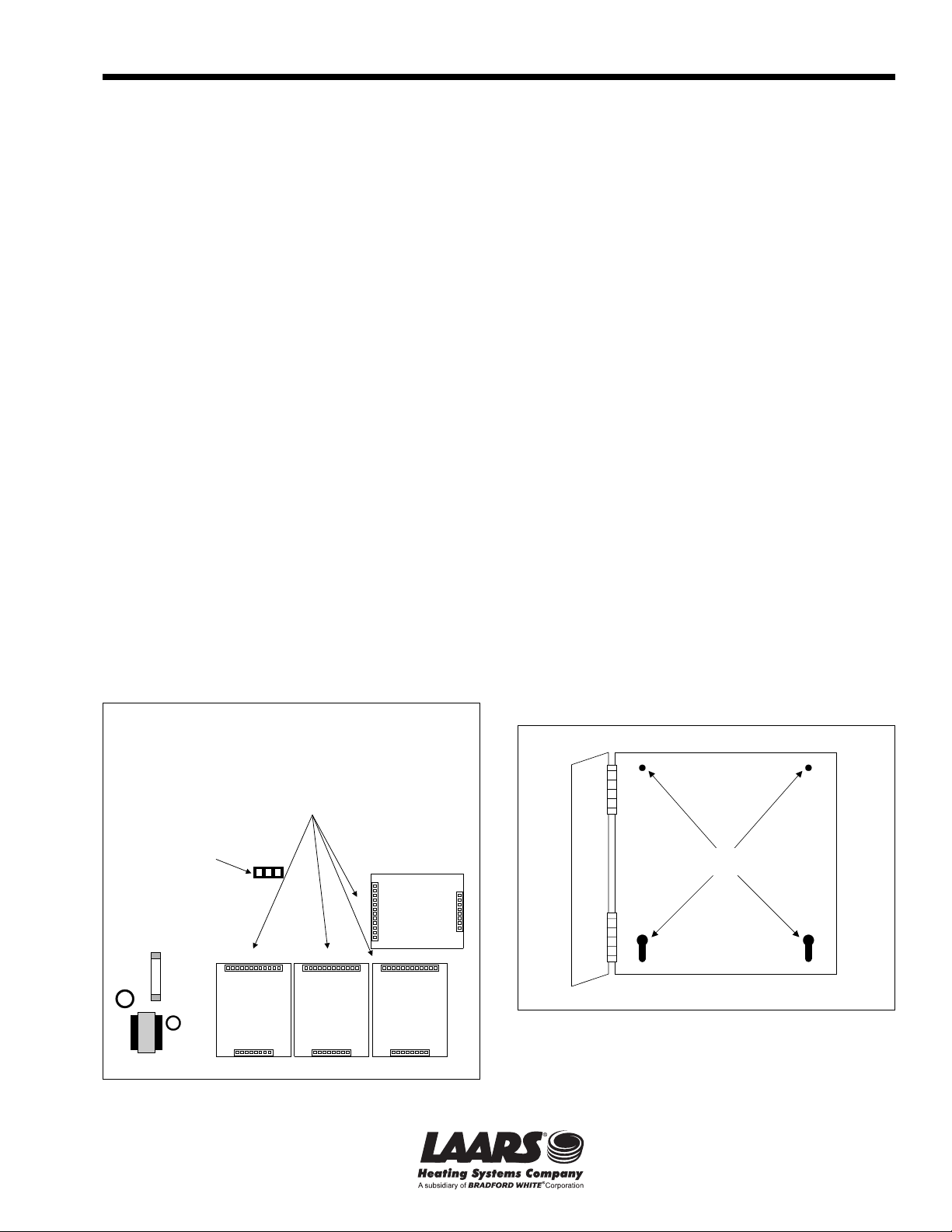
1.1 Mounting the EXM
Select a location adjacent to the MC control and
within the reach of the provided Panel-to-Panel cable.
Remove the MCX panel from the metal
enclosure by removing the top center screw and
loosening the two bottom screws. Lift the panel out.
Screw the enclosure to the surface through the
mounting holes in the back of the enclosure.
Output Cards are ordered
separately as required
Connection to
MC
Card 4 Card 3 Card 2
Fuse
Figure 1. MCX Rear View.
Mount Output
Card 4 here to
control Stages
K and L
J12
Mount Output
Card 3 here to
control Stages
IandJ
Card 1
Mount Output
Mount Output
Card 2 here to
control Stages
GandH
Mounting Holes
EandF
Card here to
control Stages
Figure 2. Mounting Holes.
Page 2
Page 2
LAARS HEATING SYSTEMS
1.2 Mounting the Output Cards
The Output Cards are mounted on the rear of the
MCX (see Figure 1).
Each Output Card controls two stages. The two
stages connected to one Output Card must have the
same type of output (135Ω, 0-5V, 1-5V, 0-10V, 210V, or 4-20mA). However, different types of Output
Cards can be combined on the MCX, and each Output
Card can be programmed differently.
Align the Output Card with the pins on the back
of the panel and gently press them on until the top of
the pins appear through the Output Card connector.
Mounting
holes
To header
MCX
J12
or
MCX
JP4
Header Cable
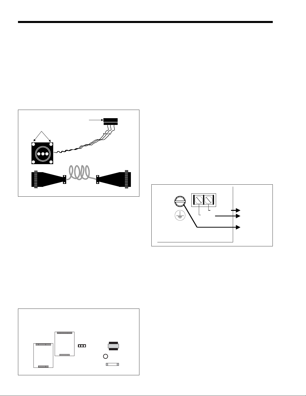
1.4 Attaching the Connecting Cable
to the MC
Remove the MC from its enclosure.
Secure the remaining Header cable to the
enclosure as described above.
On the rear of the MC, locate JP4 and attach the
three screw terminal connector.
Return the panel to its enclosure, replace the top
screw, and tighten the bottom two screws.
Reattach the Panel-to-Panel cable to the Header
cables.
1.5 Wiring the Power
Bring the 120VAC 60Hz power wires through a
bottom Knockout of the enclosure. The right front
Knockout is preferred.
Class 1 voltages must enter the enclosure
through a different opening from any Class 2 voltage
wiring.
Connect the hot line to terminal marked LINE.
Connect the neutral line to the terminal marked
NEUT.
The green ground screw MUST be connected to
earth ground (see Figure 5).
Panel-to-Panel Cable
Figure 3. Cable Connections.
1.3 Attaching the Connecting Cable
to the MCX
Disconnect the Panel-to-Panel cable from the
two Header cables (see Figure 3).
Remove a Knockout from the enclosure.
Insert the end of the Header cable with three
screw terminals through the Knockout into the interior
of the enclosure.
Use the mounting holes to secure the square end
of the Header cable to the enclosure.
Connect the three screw connector to the black
header on the rear of the MCX marked J12 (see
Figure 1).
Return the panel to its enclosure, replace the top
screw, and tighten the bottom two screws.
MC REAR VIEW
Output A&B
Output C&D
JP4
Fuse
Figure 4. MC Rear View.
Neutral
Line
SAFETY
GROUND
MUST BE
CONNECTED
Figure 5. Power Wiring.
120VAC
60 Hz
Earth
Ground
1.6 Installing the Output Relays
Each output stage (E through L) which is to be
used must have a relay installed in the socket. These
relays are ordered separately (p/n CA002300).
To install a relay, orient the pins and then press it
gently into the appropriate socket.
Any stage output which does not have a relay
must have its Mode set to Off (see MC I/O manual,
Stage Settings).
1.7 Wiring the Stage Outputs
Each Stage output (E through L) has one
Normally Open (N.O.) relay contact.
The N.O. contacts are dry contacts only. They do
not source any voltage.
Each N.O. contact is capable of switching 6A
resistive at 120VAC.
Total output of all stages must not exceed 15A.
Wire the N.O. relay contacts in series with the
unit’s limit circuit (see Figure 6).
Page 3

MC Extension Box
Page 3
Limit Circuit
1
E
2
3
F
4
Figure 6. Stage Wiring.
Class 1 voltages must enter the enclosure
through a different opening from any Class 2 voltage
wiring.
1.8 Wiring to 135
The MCX can be equipped to operate up to eight
135 Ω modulating motors.
Each pair of stages, E&F, G&H, I&J, and K&L,
are controlled by one output board.
Wire as shown in Figure 7 and Table 1.
1.9 Wiring to Current Controlled
Modulating Motors
The MCX can be equipped to operate up to eight
4-20 mA modulating motors.
To program the control for 4-20 mA output, see
the MC I/O manual (MC I/O Manual, System Startup
settings).
Apply the supplied label marked 4-20 mA below
the output terminals.
Each pair of stages, E&F, G&H, I&J, and K&L,
are controlled by one output board.
The MCX sources 24VDC excitation voltage for
the 4-20mA signal.
Wire as shown in Figure 7 and Table 1.
1.10Wiring to Voltage Controlled
Modulating Motors
The EXM can be equipped to operate up to eight
0-5 V, 0-10V, 1-5V, or 2-10V modulating motors.
To select the range, 0-5V, 0-10V, 1-5V or 210V, see the MC I/O manual (MC I/O Manual,
System Startup settings).
Apply the supplied label marked Voltage below
the output terminals.
Each pair of stages, E&F, G&H, I&J, and K&L,
are controlled by one output board.
Wire as shown in Figure 7 and Table 1.
1.11Wiring the Lockout Inputs
A closure across the pair of MCX LOCKOUT
INPUT terminals informs the MC that the particular
stages's boiler, chiller, etc. has encountered a safety
limit and can not be restarted without a manual reset.
The MC will not activate or modulate a Stage in
Lockout.
ΩΩ
Ω Modulating Motors
ΩΩ
Typical for
each stage
C1
C2 C3
B
RW
135W
E
RWB
135 W
Motor
C1
C2 C3 C4 C5 C6 C7 C8 C9 C10 C11 C12
+
-
GND
24
Current
E
-+
4 - 20mA
Motor
C1
C2 C3 C4 C5 C6 C7 C8 C9 C10 C11 C12
GND
Voltage
E
V+
GND
Voltage
Motor
C5 C6 C7 C8 C9 C10 C11 C12
C4
B RW
135W
B RW
135W
F
BRW
-
NC
GND
135 W
Motor
24
Current
+
BRW
-
NC
GND
135 W
Motor
Current
F
4 - 20mA
GND
V+NC
-+
Motor
Voltage
4 - 20mA
V+NC
-+
Motor
GND
Voltage
NC
F
V+
GND
Voltage
Motor
Voltage
Motor
G
+
24
G
G
B RW
BRW
NC
GND
4 - 20mA
Motor
GND
V+
V+
GND
135W
H
135 W
Motor
+
24
Current
H
-+
Voltage
H
Voltage
Motor
NC
V+NC
V+GND
Figure 7. Control Voltage Wiring.
A pair of LOCKOUT INPUT terminals is
provided for each stage.
The Lockout signal must be a dry contact closure
from the boiler, chiller, etc. controlled by that stage's
output.
The LOCKOUT INPUTS are dry contacts only.
No voltage can be placed across the terminals.
Wire the Lockout signals to their respective
STAGE terminals (see Figure 8):
- STAGE E to Lockout Input terminals B1&B2
- STAGE F to Lockout Input terminals B3&B4
- STAGE G to Lockout Input terminals B5&B6
- STAGE H to Lockout Input terminals B7&B8
- STAGE I to Lockout Input terminals B9&B10
- STAGE J to Lockout Input terminals B11&B12
- STAGE K to Lockout Input terminals B13&B14
- STAGE L to Lockout Input terminals B15&B16
Page 4

135W Current Voltage
Stage E
Stage F
Stage G
Stage H
Stage I
Stage J
Stage K
Stage L
Common
C2
C5
C8
C11
C14
C17
C20
C23
Increase
Mod
C3
C6
C9
C12
C15
C18
C21
C24
Decrease
Mod
C1
C4
C7
C10
C13
C16
C19
C22
SECTION 2.
Operation
2.1 EXM Status Lights
Whenever the MCX is powered, the red LED
marked POWER, located in the upper left of the panel,
should be lit. If it is not, check the 120VAC power
source.
If the MCX is correctly connected to a powered
MC, the green LED marked COMM ERROR will blink
on and off, approximately once a second. If the light is
does not blink, check the connecting cables.
If the N.O. contacts of a Stage relay are
energized, the red LED immediately to the left of the
relay will be on. If the relay is not energized, the red
LED will be off.
2.2 Display Stage Status
The percent modulation and Mode of each stage
is displayed on the main screen of the MC control (see
Figure 9). Stages in the Automatic mode which are not
active show ---.
The default screen shows Stages A through D.
Simply rotate the ADJUST knob clockwise (without
pressing) to see the remaining Stages, E through L.
Rotate the ADJUST knob counterclockwise to go
back in the Stage order.
Stages A through D correspond to the Stages
marked A through D on the MC panel.
Stages E through L correspond to Stages of the
MCX.
2.3 Stage Settings
All Stage setting are made at the MC panel.
If the COMM ERROR LED is flashing, the MC
recognizes the MCX panel and all its Stages.
Signal
Sink (GND)
C1
C4
C7
C10
C13
C16
C19
C22
Table 1.
24V
Source (+)
C2
C5
C8
C11
C14
C17
C20
C23
C3
C6
C9
C12
C15
C18
C21
C24
Carefully follow all the steps in the MC I/O
manual (Stage Settings) to set up Stages E through L.
WARNING
Each Stage, A through L MUST be setup properly.
Failure to do so will result in erratic set point control
and may cause system damage.
Dry Contact
B1
Lockout
Signal
Figure 8. Dry Contact Wiring.
140°F
<A> B C D
100% 100% 100% 100%
140°F
EFGH
100% 61% --- ---
140°F
IJKL
Off Off Off Off
Figure 9. Main Screen Display and Operation.
B2
B3
B4
B5
B6
ADJUST
PRESS TO SELECT
ADJUST
PRESS TO SELECT
GNDV+
C1
C4
C7
C10
C13
C16
C19
C22
Lockout
E
Lockout
F
Lockout
G
Rotate
Clockwise
Rotate
Clockwise
800.900.9276 • Fax 800.559.1583 (Customer Service, Service Advisors)
20 Industrial Way, Rochester, NH 03867 • 603.335.6300 • Fax 603.335.3355
1869 Sismet Road, Mississauga, Ontario, Canada L4W 1W8 • 905.238.0100 • Fax 905.366.0130
www.Laars.com Litho in U.S.A. © Laars Heating Systems 0806 Document 4206
 Loading...