

Page 1
Installation, Operation and Maintenance Instructions Document 1106D
Installation,
Operation and
Maintenance
Instructions for
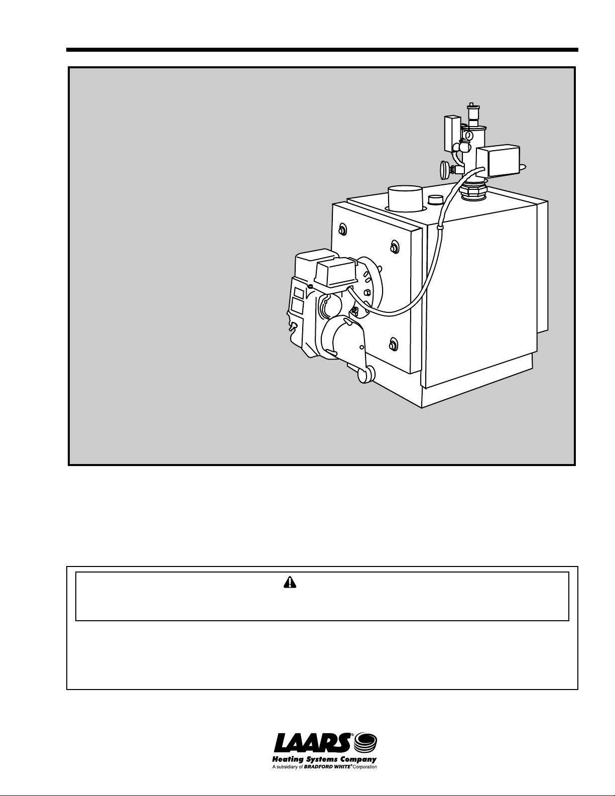
MAX
Residential
Oil-Fired Boiler
Models MAX 75 (DV)
MAX 100 (DV)
MAX 120 (DV)
MAX 140 (DV)
MAX 165 (DV)
FOR YOUR SAFETY : This product must be installed and serviced by a professional service technician,
qualified in boiler installation and maintenance. Improper installation and/or operation could create
carbon monoxide gas in flue gases which could cause serious injury, property damage, or death.
Improper installation and/or operation will void the warranty.
W ARNING
If the information in this manual is not followed exactly , a fire or explosion may result causing
property damage, personal injury or loss of life.
Do not store or use gasoline or other flammable vapors and liquids in the vicinity of this or any
other appliance.
Installation and service must be performed by a qualified installer , service agency , or fuel oil
supplier.
READ AND SAVE THESE INSTRUCTIONS FOR REFERENCE
70-196D
Page 2

Page 2
LAARS Heating Systems
TABLE OF CONTENTS
SECTION 1.
General Information
1A. Introduction...................................................3
SECTION 2.
Technical Specifications
2A. Boiler Outputs ............................................... 5
SECTION 3.
Installation
3A. Freight Claims............................................... 6
3B. Regulations ...................................................6
3C. Sizing the System ......................................... 6
3D. Location ........................................................6
3E. Clearance ..................................................... 6
3F. Combustion Air (other than direct vent) ......... 6
3G. Ventilation Air (conventional chimney
and direct vent) ............................................. 7
3H. Chimney Connection ..................................... 7
3I. Direct Vent Balanced Flue System................ 8
3J. Installation of Balanced Flue System ............ 9
3K. Boiler Piping..................................................9
3L. Freeze Protection ......................................... 9
3M. Indirect Hot Water Tank.............................. 10
3N. Burner Controls ........................................... 10
3O. Fuel System................................................ 10
3P. Gravity Head System .................................. 10
3Q. Suction Lift System ..................................... 10
3R. Oil Filter ...................................................... 10
3S. Wiring .........................................................10
SECTION 4.
Operation
4A. Preliminary Burner Settings......................... 19
4B. Burner Adjustments..................................... 19
4C. Sequence of Operation ............................... 19
SECTION 5.
Maintenance and Service
5A. Boiler .......................................................... 22
5B. Oil Burners.................................................. 22
5C. Oil Filter ...................................................... 22
5D. Cold Oil ....................................................... 22
SECTION 6.
Homeowner Information
6A. Living With Your Boiler ................................ 22
6B. General Information .................................... 23
SECTION 7.
Part Numbers
................................................................... 23
Page 3

MAX Oil-Fired Boiler
SECTION 1.
General Information
1A. Introduction
The MAX Boiler has been constructed to meet
the stringent requirements of the ASME Boiler Codes
and designed to provide a rapid response to hot water
and heating demands at a very high thermal efficiency.
This is a low mass boiler. To take advantage of
this feature, and prevent short cycling, always select
the lowest firing rate satisfactory for the load
requirement.
The boiler is supplied either for connection to a
conventional chimney or comes complete with a
balanced flue system for direct venting through the
wall.
With the balanced flue system, air for
combustion is drawn from outside through a terminal
and ducted directly to the burner, making the boiler
virtually room sealed. Flue gases are discharged
through the same terminal so that wind pressures are
applied equally to inlet and outlet, making it a true
balanced flue system. A silencer is also incorporated
in the terminal to reduce the flue gas discharge noise.
This is a particularly useful feature if the terminal is
located near a bedroom window or adjacent to
neighboring properties.
The boiler is constructed with two concentric
water jackets, the inner one forming the furnace tube
and the outer the flue gas annulus. Flue gas retarders
fitted around the annulus are specifically designed to
extract the maximum heat from the gases with
minimum pressure loss.
Page 3
The simple annular design also makes it possible
to keep the water content to a minimum (only 3.2 gals.
[12L] for the MAX (DV) 75, 100, 120 and 5.1 gals.
[19L] for the MAX (DV) 140, 165). Because of this
low mass, water is rapidly heated to the temperature
demands. Another benefit of the low thermal mass is
the insignificant level of standby loss when the burner
shuts down.
To achieve the best possible heat transfer, the
boiler is designed on the “Series Flow” principle
whereby the return water is preheated by first passing
through the outer water annulus before coming into
contact with the furnace tube. This arrangement also
provides a counter flow of flue gases and water so that
the coolest gases come into contact with the coolest
water for the most efficient heat transfer.
Heavily insulated doors at front and back of
boiler, provide easy access for cleaning and
inspection, with the burner being swung on the front
door either left or right as required.
Accurate sensing of temperature and pressure is
assured by grouping all controls and safety devices on
a common supply manifold.
The use of the latest flame retention head burner
allows the boiler to operate under a slight positive
pressure which ensures stable combustion under
virtually all operating conditions.
MAX (DV) GPH Nozzle Pump Input AFUE Heating Water Shipping
Model Rate Size Pressure MBTH/hr Rating Capacity Content Weight
75 0.72 0.65 140 101 87.0 85,900 3.0 12 324 147
100 1.00 0.85 140 140 86.5 121,200 3.2 12 324 147
120 1.20 1.00 140 168 86.0 141,600 3.2 12 324 147
140 1.40 1.20 150 196 85.6 166,000 5.1 19 431 196
165 1.65 1.35 150 231 85.0 192,400 5.1 19 431 196
GPH P.S.I. % BTU/h gal. L lbs. kg
Table 1. Boiler Specifications.
Page 4
Page 4
LAARS Heating Systems
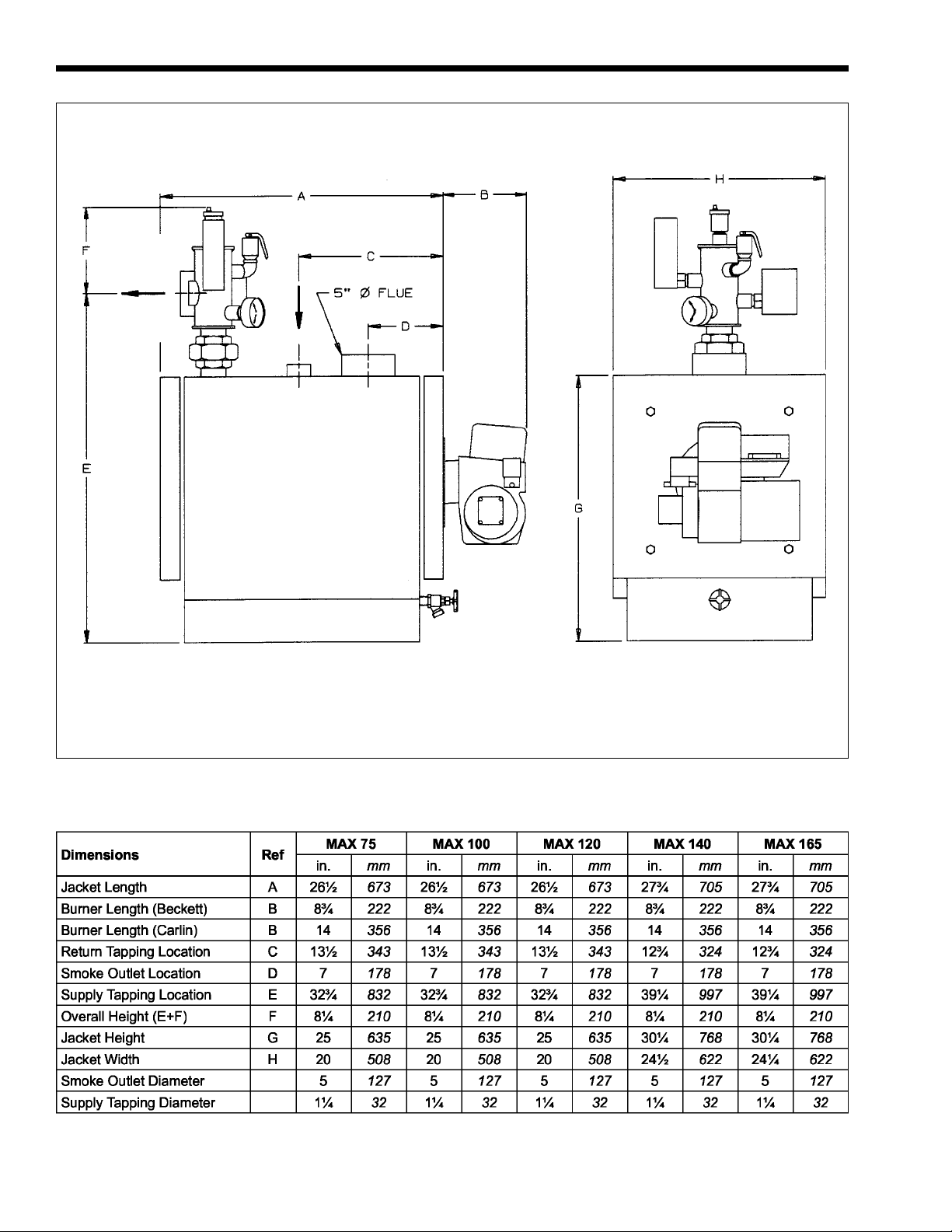
(127mm)
Side Front
Figure 1. Boiler Dimensions (refer to Table 2).
Table 2. Boiler Dimensions.
Page 5
MAX Oil-Fired Boiler
Page 5
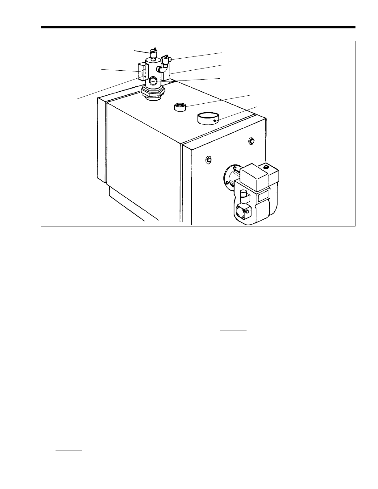
Auto Air Vent
Honeywell L4006E High Limit Aquastat
(Manual Reset)
1¼" Supply
¾" Relief Valve
Honeywell L8148 Aquastat
Temperature / Pressure Gauge
1¼" Return
Flue Gas
Sampling Plug
Figure 2. Controls Layout.
SECTION 2.
Technical Specifications
2A. Boiler Outputs
Boiler constructed and hydrostatically tested in
accordance with ASME Boiler code Section IV.
Beckett / Carlin / Riello (model varies) Oil
Burner complete with flame retention head,
Honeywell control and cad. cell. or equivalent
(A post purge timer and oil solenoid valve is
fitted to direct vent burners)
Honeywell L8148A Aquastat Relay.
Honeywell L4006E High Limit Aquastat
(manual reset - direct vent boilers only)
Temperature and pressure gauge.
Pressure relief valve 3/4"
Automatic air vent
Air eliminator built into supply manifold
Boiler drain valve 1/2"
• 2500-004: 15-foot vent kit contains 15-feet of 5"
stainless steel pipe (for vent) and 15-feet of 4"
aluminum (for ducted air), with clamps, adapters,
heatshield and silicone.
•
2500-009: Direct vent terminal (Univent
terminal) to be used with either 10-foot or 15foot vent kits, for all MAX DV boiler sizes.
In addition, the following vent terminal extensions
can be used to bring the terminal above grade level to
meet code requirements:
•
2500-010: Vent terminal extension for 75, 100 and
120
•
2500-011: Vent terminal extension for 140 and 165
Balanced Flue System Kits
(direct vent boilers only)
For direct venting, vent pipe kits and vent
terminals are available.
•
2500-002: 10-foot vent kit contains 10-feet of 5"
stainless steel pipe (for vent) and 10-feet of 4"
aluminum (for ducted air), with clamps, adapters,
heatshield and silicone.
Page 6

Page 6
LAARS Heating Systems
SECTION 3.
Installation
3A. Freight Claims
The boiler and it's components should be
inspected for damage upon arrival and any claim filed
immediately against the carrier by the consignee. The
carrier is responsible for taking prompt action on all
claims.
3B. Regulations
THE BOILER INSTALLATION MUST BE
CARRIED OUT BY A QUALIFIED INSTALLER
IN ACCORDANCE WITH THE REGULATIONS
OF AUTHORITIES HAVING JURISDICTION
AND CSA STANDARD B139 or ANSI / NFPA 31
Installation of Oil Burning Equipment - latest edition,
the
National Electrical Code ANSI / NFPA 70 - latest
edition and local codes and authorities having
jurisdiction. Such applicable requirements take
precedence over the general requirements contained
herein.
The installer must also be properly licensed and
experienced in all the codes and ordinances.
WARNING
In the interest of safety, gasoline or other flammable
fluids or vapors must not be stored or used in the
vicinity of the boiler.
3C. Sizing the System
Over sizing the boiler will cause short cycling
and reduce its operational efficiency, so it is
recommended that a building heat loss calculation is
made to ensure that the correct size boiler is used
(see Table 1).
3D. Location
The boiler should be mounted on a solid level
floor and located as close as possible to the chimney
or the position chosen for the direct vent terminal.
The boiler can be mounted on a combustible floor due
to its wet base construction, however, a check should
be made to ensure the floor is capable of supporting
the installed weight of the boiler including its water
content.
A closet may be used to enclose the boiler,
providing the enclosure is properly vented to ensure
the controls do not become overheated (see
Ventilation Air section). The boiler must also have the
correct amount of air available for combustion when
using a conventional chimney (see Combustion Air
section).
When installed,
necessary use metal shims under the base to level the
the boiler must be level. If
unit particularly front to back otherwise air could be
trapped inside the boiler.
3E. Clearance
Adequate clearance should be allowed around
the boiler for cleaning and servicing. The following
minimum clearances are recommended:
Front - 24" (610mm) (for hinging door)
Rear - 6" (152mm)
Sides - 6" (152mm)
Clearance from combustible materials should be in
accordance with local and national codes. Guidance is
given in the National Fire Protection Bulletin NFPA,
Installation of Oil Burning Equipment. All other
applicable codes should also be followed.
3F. Combustion Air
(other than direct vent)
WARNING
As an additional measure of safety, Laars strongly
recommends installation of suitable Carbon
Monoxide detectors in the vicinity of this appliance
and in any adjacent occupied spaces.
AVERTISSEMENT
Laars recommande fortement, comme mesure de
sécurité supplémentaire, l'installation de détecteurs
de monoxyde de carbone adaptés dans le voisinage
de l'appareil et dans chacune des pièces habitées
adjacentes.
Chimney Vent: For boilers installed in
basements, infiltration may be adequate to provide
combustion air. For buildings of exceptionally tight
construction, the boiler must be installed in an
unconfined space, or in an area which directly
communicates with an unconfined space. An
unconfined space is a space whose volume is 50 cubic
ft. (1.4m3) or more per 1,000 BTU (293kW) of the
aggregate input of all appliances in that space. Two
openings to the space, one 6" (152mm) from the floor
and one 6" (152mm) from the ceiling of the enclosure
must be provided. Each opening must have at least
168 square inches (1084 sq.cm) of free area.
Chimney Vent with outside air duct connected
directly to burner: In an installation of exceptionally
tight construction, intake air may be ducted directly to
the burner from the outdoors. On an AF2 burner
remove the black air intake shroud to connect the 4"
(102mm) aluminium duct (up to 15 equivalent ft.
[4.6m] maximum). Terminate the duct on the outside
of the building with a suitable protective cover. This
cover must be located at least 16" (406mm) above
grade or above an anticipated snow line.
Page 7
MAX Oil-Fired Boiler
Page 7
On Carlin EZ-1 burners install model # 97406
combustion air intake system.
3G. Ventilation Air
(conventional chimney and
direct vent)
Where the boiler is installed in a basement there
is normally sufficient air infiltration to provide
adequate ventilation.
Where the boiler is installed in a closet or
otherwise confined space ventilation must be provided
to keep the controls from overheating. This is
accomplished by providing two openings to the space,
one 6" (152mm) from the floor and one 6" (152mm)
from the ceiling.
3H. Chimney Connection
Caution
An oil-fired unit shall be connected to a vent having
sufficient draft at all times to ensure sfe and proper
operation of the unit.
The chimney must be inspected and thoroughly
cleaned before connecting boiler. Most local codes
require the chimney to be lined when using an oil fired
boiler in order to protect the bricks and mortar from the
condensation produced by modern high efficient boilers.
The chimney must terminate at least 3 ft. (0.9m)
above the point where it passes through the roof and
be in a position free from down draft.
The boiler should be connected to the chimney
with the shortest possible run of 5 in. flue pipe and be
located above the chimney base to allow a drop leg for
scale accumulation to avoid blocking flue pipe
entrance.
Horizontal runs should be pitched up towards
chimney at approximately 1/4 inch per foot.
Install balanced damper on chimneys higher than
20 feet (6.1m).
Install "Blocked Vent Switch" provided in
accordance with attached instructions. Follow all
Warnings, Cautions and Maintenance Instructions for
safe, trouble free operation.
IMPORTANT: Max 75-140 may condense
when vented into an outside chimney. To minimize
potential for condensing, install either thermostatic
union or recirc bypass, shown in Figures 12 and 13.
As the boiler and flue pipe are under slight
positive pressure on start-up, it is necessary to seal all
pipe joints with high temperature tape or silicone
sealant to avoid any flue gas leakage into room.
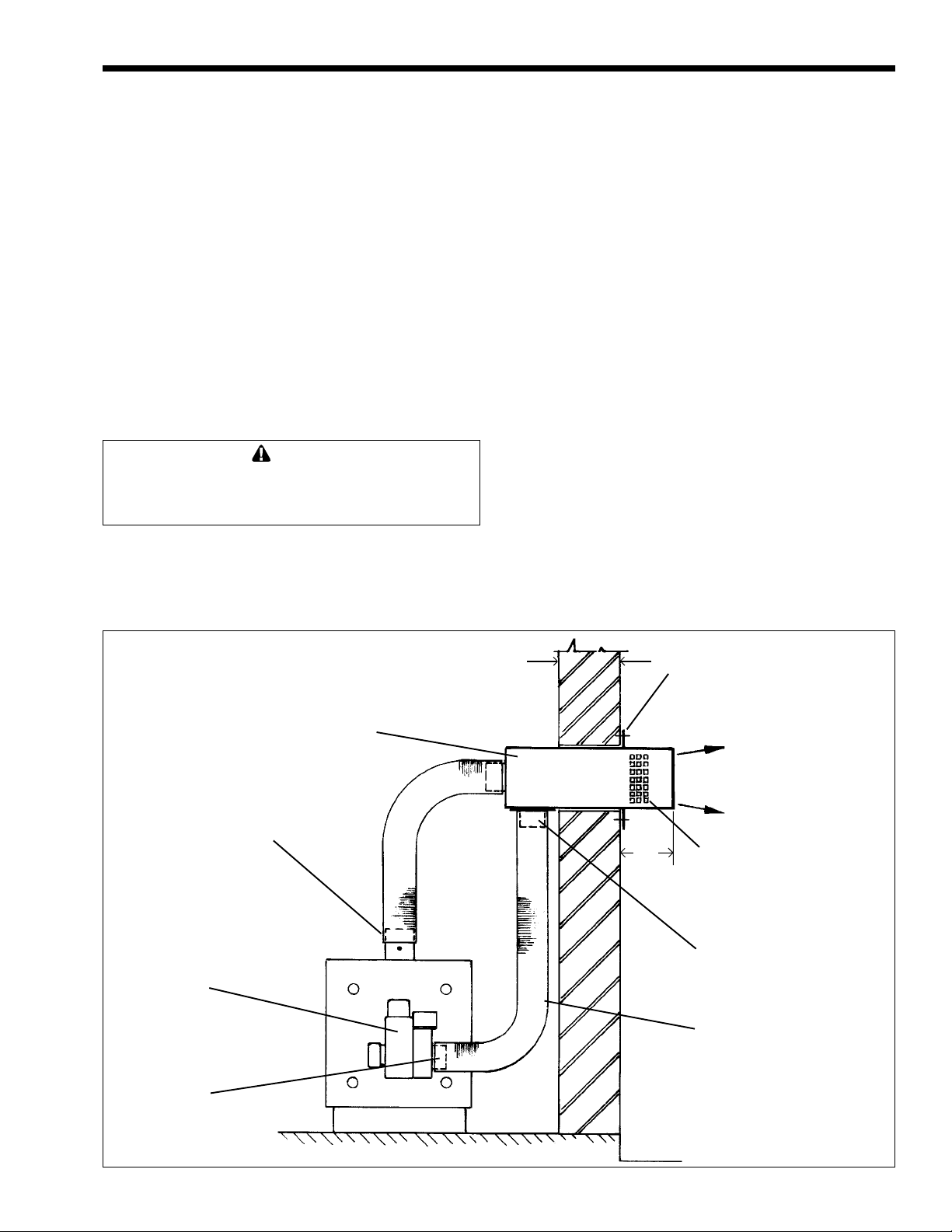
5" diameter flue pipe secure both ends of
pipe with clamps and
seal with silicone
Oil Burner
Burner Intake Air
& Adaptor
Balanced Flue T erminal
10" max.
Flange Fix to Wall
Ð
Ï
6½"
Gas Flue Discharge
Air Intake Screen
4" pipe adapter
4" diameter air pipe - secure
both ends
with clamps
Figure 3. Direct Vent Balanced Flue System.
Page 8
Page 8
³
Minimum 1.5
(0.5)
LAARS Heating Systems
3
³
4
(1.2)
(0.9)
³
³
7
(2.1)
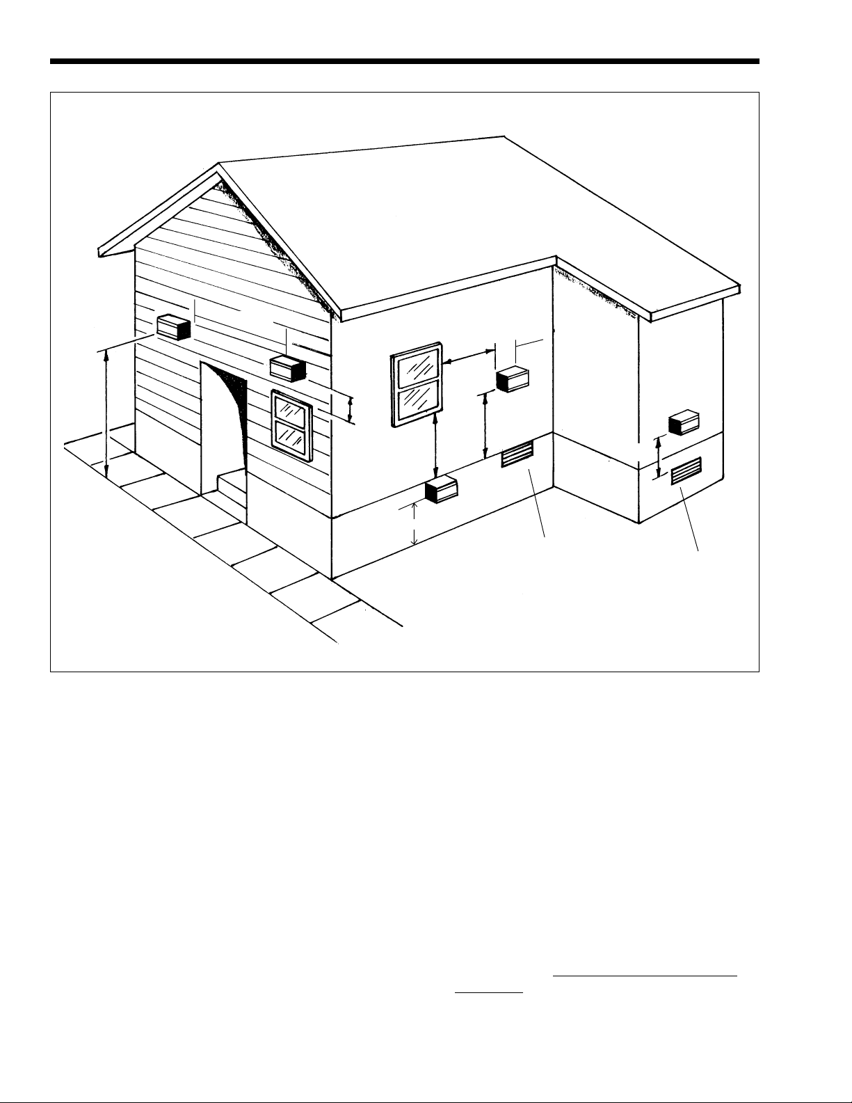
Figure 4. Terminal Locations - Minimum Distances.
1
(0.3)
3I. Direct Vent Balanced Flue System
With this system flue gases are vented directly
through the wall and fresh air for combustion is drawn
in through the same terminal, thus ensuring wind
pressures are equal to the intake and flue gas
discharge to create a balanced flue condition.
The terminal also incorporates a silencer to
reduce the flue gas discharge noise and a specially
designed end cap which throws the flue gases clear of
the wall to avoid surface discoloration.
NOTE: If the burner is not correctly adjusted it
is possible that surface discoloration may occur. Laars
will not accept any responsibility for such
discoloration.
The position chosen for the Balanced Flue
Terminal must conform to the following guidelines:
1. The terminal shall not be less than 3 ft. (0.9m)
above or 10 ft. (3m) horizontally from any forced
air inlet into the building.
1.5
(0.5)
1
(0.3)
Gravity Air Inlet
1 (0.3)
4
(1.2)
3
(0.9)
Forced Air Inlet
Dimensions shown in feet (m).
2. The terminal shall not be less than 4 ft. (1.2m)
below, 4 ft. (1.2m) horizontally or 1 ft. (0.3m)
above any door, window, or gravity air inlet into
the building.
3. The terminal shall not be less than 3 ft. (0.9m)
from an inside corner of an L shaped building.
4. The terminal shall not be less than 7 ft. (2.1m)
above grade when located adjacent to public
walkways.
5. The terminal shall not be less than 2 ft. (0.6m)
from an adjacent building.
6. IMPORTANT: The terminal shall be located at
a height not liable to blockage from leaves, snow
or other debris,
at least one foot (0.3m) above
grade level.
7. The terminal shall be positioned so that flue gases
are not directed where they can jeopardize people,
overheat combustible structures, or enter buildings.
Page 9

MAX Oil-Fired Boiler
Page 9
8. As the balanced flue vent system operates under
a slight positive pressure it is essential to seal all
flue joints to prevent leakage of flue gases into
the building.
certified pressure venting.
9. Vent terminal should be well away from
shrubbery or other obstructions that would
prevent free air flow to and from vent terminal.
Do not terminate vent under decks, stairways, or
car ports. When ever possible, locations under
windows should be avoided.
10. Vent termination should not be mounted
directly above or within 3' horizontally from
an oil tank vent.
Vent exhaust piping must be
3J. Installation of Balanced Flue System
1. Having decided the location for the terminal, cut
a hole in wall 7.5" high x 10.5" wide (191 x
267mm).
2. Insert terminal through the hole from outside and
screw to wall at the fixing flange, after applying a
bead of silicone sealant on the back face of the
flange.
3. Fit the 5 in. flexible pipe between end of
terminal and boiler flue outlet, cutting pipe to
suit installation. Secure both ends of pipe with
clamps and seal with silicone sealant to prevent
any flue gas leakage.
The pipe should rise from the boiler to terminal
and be supported at regular intervals dependent upon
length of pipe used.
Terminal must be installed pitching down to outside
¼" per foot to prevent rain entering vent piping.
Notes: (a) The “Univent” terminal is certified
for use with zero clearance from combustible
materials. The connection between the flue pipe and
the balanced flue terminal must be provided with a 6"
(152mm) clearance from combustibles or any reduced
clearance acceptable to NFPA 31. P/N 70-330
(included with all direct vent kits) may be installed on
the balanced flue terminal to reduce the required
clearance to 2" in accordance with NFPA 31.
(b) The terminal is packed with insulation and is
also air cooled thus making it suitable for installation
through combustible walls.
4. Fit the 4 inch pipe adapter to the underside of
terminal and connect the 4 inch flexible pipe
between adapter and air intake ring on burner
after first removing the black shroud. Cut the
pipe to suit installation and securely fasten to
burner and terminal with three fixing screws.
Support pipe at regular intervals dependent upon
length.
5. Finally, seal all around terminal on inside of wall
with silicone sealant.
Note:
“Univent” suitable for wall thickness up
to 10" (229mm).
3K. Boiler Piping
The supply manifold (control center) provided
with the boiler comes equipped with an air eliminator
provided through an automatic float vent. This will
provide system air elimination. Unit may be piped into
a non diaphragm expansion tank utilizing this
connection.
The pressure relief valve should be piped to a
safe place of discharge.
The piping and related connections should
follow good practice using approved joint sealants and
conform with all state and local codes. When the
boiler is connected to applications where standby
temperatures may drop below 60°F (16°C) or to a
large volume of water (e.g. radiant floors) then an anticondensing means must be provided. This may be
accomplished utilizing a by-pass loop (see Figure 12)
or optional thermostatic union (see Figure 13) p/n
2400-030.
Note: This is a low mass boiler. Follow
suggested piping diagrams to minimize the chance of
short-cycling.
3L. Freeze Protection
Proper precautions for freeze protection are
recommended for boiler installations in areas where
the danger of freezing exists.
Power outage, interruption of oil supply, failure
of system components, activation of safety devices,
etc., may prevent a boiler from firing. Any time a
boiler is subjected to freezing conditions, and the
boiler is not able to fire, and/or the water is not
able to circulate, there is a risk of freezing in the
boiler or in the pipes in the system. When water
freezes, it expands. This can result in bursting of
pipes in the system, or damage to the boiler, which
could result in leaking or flooding conditions.
Freeze protection additives may be used. Do not
use automotive anti-freeze. Maintaining a mixture of
minimum 65% water and maximum 35% properly
inhibited HVAC glycol, which contains an antifoamant, is the preferred method of freeze protection
for Max boilers. Percentage of glycol used in the
Max boiler must not exceed 35%. Typically, this
mixture will serve as freeze protection for
temperatures down to approximately 0°F (-18°C), and
will serve as burst protection for temperatures down to
approximately –35°F (-30°C).
IMPORTANT NOTES: Different glycol
products may provide varying degrees of protection.
Glycol products must be maintained properly in a
heating system, or they may become ineffective.
Consult the glycol specifications, or the glycol
manufacturer, for information about specific products,
maintenance of solutions, and set up according to your
Page 10

Page 10
LAARS Heating Systems
particular conditions
3M. Indirect Hot Water Tank
Install the tank in accordance with the
manufacturers instructions using recommended pipe
sizes, location of temperature / pressure relief valve
and any other special requirement for correct
installation.
A thermal expansion tank may be required on
hot water tanks equipped with check valves or back
flow preventors on the cold water supply.
3N. Burner Controls
The burner is fitted with a fully automatic
control system which incorporates a cad cell to
monitor the flame and shut down the burner in the
event of flame failure. A push button is provided to
restart the burner, but this must never be pressed more
than once following a flame failure.
Pre-purge (direct vent only) provides an air
supply prior to oil flow to ensure clean combustion
under all conditions.
Post purge is also fitted to direct vent burners to
completely clear all residual gases from the boiler and flue
system. This is necessary with direct vent flues because of
the lack of draft prevailing after the burner shuts down. The
post purge time is factory set at 30 seconds.
3S. Wiring
Wiring connections between burner and aquastat
on supply manifold should be made in accordance with
wiring diagrams in this manual (see Figures 5 through
11). External wiring must be in accordance with local
codes and regulations.
For convenience of servicing, a fuse disconnect
switch should be fitted near the boiler. Field
connections should be protected with a 15 amp fuse.
If an indirect hot water tank is used, the aquastat
on tank should be wired so as to have preference over
heating of the building. This requires the use of a
Honeywell L6006A-1145 or equivalent aquastat on
the tank working in conjunction with a zone valve or
circulator relay. See wiring diagrams in this manual.
On boilers piped direct (no zones) set anticipator
on thermostat to 0.8 amps.
3O. Fuel System (oil supply no heavier
than #2 fuel oil)
The oil supply should be run in heavy walled
copper tubing, without any joints, using flared fittings
only. It is important that the oil feed line to the burner
is air tight otherwise firing problems could result.
3P. Gravity Head System
Where the fuel supply is level with or above the
burner only a single pipe is required.
3Q. Suction Lift System
Where the burner is above the fuel supply a
return line must be provided in addition to the supply
line. The arrangement requires the fitting of the
bypass plug (provided) in the return port of the fuel
unit. Air is automatically purged from the fuel unit
and returned to the storage tank with this arrangement.
NOTE: If the suction lift exceeds 10 feet (3m),
a two stage fuel unit should be used. For Riello
burners obtain C700 kit for respective burners.
3R. Oil Filter
An in-line oil filter should be fitted in the supply
line and located inside the building between the tank
shut-off valve and as near to the burner as possible. A
shut-off valve should also be located close to the
burner for ease of servicing.
Page 11

MAX Oil-Fired Boiler
Page 11
Figure 5. Internal Wiring with Beckett AF II, AFG and CF375 with Honeywell R7184P Control.
Page 12

Page 12
LAARS Heating Systems
Figure 6. Internal Wiring with Carlin EZ-1.
Page 13

MAX Oil-Fired Boiler
Page 13
Figure 7. Internal Wiring with Riello BF5 (direct vent).
Page 14

Page 14
LAARS Heating Systems
Figure 8. Wiring Diagram. Boiler Only. Zoning with Zone Valves.
Figure 9. Wiring Diagram. Boiler Only. Zoning with Circulators.
Page 15

MAX Oil-Fired Boiler
Page 15
Figure 10. Wiring Diagram. Boiler with Indirect Water Heater. Zoning with Zone Valves.
Figure 11. Wiring Diagram. Boiler with Indirect Water Heater. Zoning with Circulators.
Page 16

Page 16
LAARS Heating Systems
Figure 12. Piping Diagram. “MAX” Boiler with Indirect Water Heater. Zoning with Zone Valves.
Figure 13. Piping Diagram. “MAX” Boiler with Indirect Water Heater. Zoning with Circulators.
Page 17

MAX Oil-Fired Boiler
Page 17
Figure 14. Piping and Wiring Diagrams. MAX Boiler in a Radiant Application.
Page 18

Page 18
Figure 15. Piping Diagram. MAX Boiler with Buffer Tank for Multi-Zone Application.
LAARS Heating Systems
Page 19

MAX Oil-Fired Boiler
Page 19
SECTION 4.
Operation
1. Check the boiler service switch is in the off
position.
2. Check the boiler is filled with water and the
complete system is purged of air.
3. Check the “cold fill” pressure is correct - usually
12 p.s.i.
4. Check there is ample oil in the storage tank and
all manual shut-off valves in the fuel system are
OPEN.
5. Set limit switch located in L8148A aquastat at
200º F (93°C).
6. Set manual reset limit switch at 220º F (104°C)
(Direct Vent Boilers Only).
7. Carry out burner settings, see “Preliminary
Burner Settings” (Table 3).
8. Push the safety reset button on burner control and
release. Adjust room thermostat or tank aquastat
to call for heat, switch ON boiler service switch
and burner should start.
Caution
When using a direct vent system -
If smoke is seen coming from the vent terminal,
switch off burner immediately. Otherwise the outside
wall could be discolored. Check “Preliminary Burner
Settings” again.
9. On one pipe systems the pump should be bled as
soon as the burner motor starts. Bleed oil into a
container for at least 15 seconds until it is seen
to be free of air bubbles.
With two pipe suction systems, the air is returned
to the oil storage tank where it is dissipated.
10. Adjust burner to achieve the reading shown under
4B “Burner Adjustments.”
11. If burner fails to start, check “Trouble Shooting
Guide” (Table 4).
4A. Preliminary Burner Settings
1. Fit the nozzle to suit firing rate required
2. Set air dial to the appropriate setting
3. Fit correct number stop pin or positioning bar to
burner.
4. Fit a pressure gauge to the fuel pump.
4B. Burner Adjustments
Test equipment required:
CO
analyzer Stack thermometer
2
Draft gauge Smoke tester
Fuel pressure gauge
Test readings should be taken from the plug in
the flue collar. Over the fire sampling is not
necessary on pressure fired boilers.
NOTE: Do not drill into the flexible vent pipe.
After firing the burner for about 5 minutes, make
the following checks and adjustments:
1. Check the pump pressure and if necessary adjust
pressure to obtain 140 / 150 p.s.i.
2. Gradually close air dial until a slight smoke trace
is measured, then take a flue gas sample and
check CO
3. Open air dial to reduce CO
reading which should be about 13%.
2
by ½%, then lock
2
dial in this position.
NOTE: The slight increase in excess air
provides a built in margin to ensure clean combustion
throughout the heating season.
(4) The vent pressure of the MAX DV will vary
dependent upon length of vent pipe used and the
firing rate chosen.
If pressure exceeds 0.13" W.C. recheck burner
setup for excess air / low CO
reading.
2
NOTE: With conventional chimneys the
pressure loss will be less because of the higher draft
normally generated.
5. Flue gas temperature will vary according to the
firing rate. The following typical net
temperatures should be obtained after
approximately 15 minutes of burner operation.
Note that the temperatures listed are net
temperatures. The net temperature listed should
be compared to the measured (actual)
temperature minus the temperature of the
combustion air. (i.e. use the outside temperature
when the combustion air is ducted, and use the
room temperature when room air is used for
combustion:
320°F @ 0.75 GPH (160°C @ .75mL/s)
350°F @ 1.00 GPH (177°C @ 1mL/s)
420°F @ 1.20 GPH (216°C @ 1.20mL/s)
330°F @ 1.40 GPH (166°C @ 1.40mL/s)
410°F @ 1.65 GPH (210°C @ 1.65mL/s)
4C. Sequence of Operation
When the room thermostat or hot water tank
aquastat calls for heat the burner and circulating pump
start. The burner and pump continue to run until the
heat demand is satisfied - the hot water tank being
satisfied before the room heating requirements.
If the boiler water reaches the high limit setting of
200º F (93°C) the burner will shut off but the pump
will continue to operate to clear the residual heat.
When the boiler temperature falls the burner will
restart if there is still a demand for heat.
A manual reset high limit aquastat (set at 220ºF)
(104°C) is provided on Direct Vent Boilers to shut off
the burner in the event of a failure of the high limit
control.
The burner features a post purge timer on Direct
Vent Boilers which provides a timed overrun of the fan
to clear residual flue gases from the boiler and flue
system after combustion is shut off.
Page 20

Page 20
0.75
MAX DV
LAARS Heating Systems
1.00
MAX DV
1.20
MAX DV
1.40
MAX DV
1.65
MAX DV
Refer to Rating Label for draft settings.
Table 3. Preliminary Burner Settings.
The minimum and Maximum flue outlet
pressures, measured at the flue gas sampling plug,
shall be –0.15 in. W.C. and -0.01 in. W.C.
Page 21

MAX Oil-Fired Boiler
Page 21
FAULT
BURNER
DOES NOT
START
BURNER RUNS
BUT FLAME NOT
ESTABLISHED
POSSIBLE CAUSE ACTION
Primary safety control tripped
High limit thermostat or blocked vent switch
tripped (MAX only)
Thermostat satisfied Turn thermostat to a higher setting.
Fuse blown or breaker tripped
Check voltage at burner between orange If voltage confirmed replace primary control.
and white wires If no voltage check t-stat and wiring connects.
Motor or fuel pump seized
Cad. cell dirty or faulty Clean face or replace cell.
No oil supply Check oil level in tank and oil supply to burner.
Water in oil tank Drain water from tank and bleed line to burner.
Nozzle plugged Replace with nozzle specified in manual.
Ignition transformer faulty
Electrodes carboned or shorting Clean electrode and check settings.
MAX-DV blocked vent or air intake Clear debris from around vent terminal.
Press reset button on control.
Note: ONLY PRESS ONCE.
Press reset button on both controls.
Fit new fuse or reset breaker. If it blows again,
check for short circuit.
Turn off power to burner and rotate by hand.
Replace if necessary.
Check quality of spark and replace transformer
if necessary.
FLAME
ESTABLISHED
THEN BURNER
LOCKS OUT
BURNER
PULSATES
Faulty oil valve Replace valve.
Too much combustion air Reduce air setting to obtain 11 to 12% CO2.
Low oil pressure Check pump pressure and adjust to 140 psi.
Water in oil tank Drain water from tank and bleed line to burner.
Oil filter or pump strainer plugged Replace filter cartridge and clean strainer.
Too much or too little combustion air Adjust air control to obtain 11 to 12% CO2.
Air trapped in fuel pump Bleed off air from pressure gauge port.
Low oil pressure Check pump pressure and adjust to 140 psi.
Lack of combustion air Check terminal for block at air intake screens.
Terminal fouled with debris at flue gas outlet Remove end cap and clean outlet.
Incorrect air setting Adjust air control to obtain 11 to 12% CO2.
Air leakage into fuel system Bleed pump and seal air leaks.
Water in oil tank Drain water from tank oil at burner.
Incorrect pump pressure Check oil pressure and adjust to 140 psi.
Pump coupling worn or broken Replace coupling.
Nozzle partially pluggeD Replace with nozzle specified in manual.
Boiler flue ways fouled Brush out all flue deposits.
Table 4. Troubleshooting.
Page 22

Page 22
LAARS Heating Systems
SECTION 5.
Maintenance and Service
To maintain the boilers high thermal efficiency
and reliable operation, it should be serviced and the
vent system inspected every year by a qualified
service person.
The service should preferably be carried out
directly after the heating season so as to avoid any
unnecessary corrosion.
5A. Boiler
The boiler flue ways may be cleaned by
swinging open front door after disconnecting flexible
air pipe and oil line from burner.
Remove the baffles from the flue gas annulus,
brush out scale deposits with a flexible brush and
remove with a vacuum cleaner. The rear door can
also be taken off if required to gain access for a
complete inspection of the internal flue ways. When
replacing doors ensure that they are fully tightened to
make a gas tight seal.
5B. Oil Burners
Clean combustion head assembly and all air
handling parts. Inspect condition of nozzle and
replace if necessary with a nozzle of the same make
and specification.
Check the electrode settings are in accordance
with the oil burner instructions. Also ensure the high
voltage leads are firmly secured to the ignition
electrodes. Clean all deposits from blower wheel
blades. Clean screen in fuel pump.
5C. Oil Filter
Replace the oil filter cartridge with one of the
same specifications.
SECTION 6.
Homeowner Information
WARNING
Never use gasoline, waste oil or garbage in your
boiler.
Never try to ignite oil by tossing burning paper or
other material into your boiler.
Never leave combustible materials around
your boiler.
Never tamper with the boiler controls or
burner settings.
6A. Living With Your Boiler
1. Shut down Instructions
a. Switch OFF boiler service switch.
b. Close all manual fuel shutoff valves.
c. If the boiler is going to be off for an extended
period of time and the threat of freezing
exists, drain water from boiler and heating
system.
Caution
Always keep the oil supply valve shut off, if the
burner is shut down for an extended period of
time.
2. Care of shut down boiler and restarting after an
extended shut down
a. Keep area around boiler clean and free of
litter during shut down.
b. Restarting should be done by a qualified
Service Person after inspecting the vent
system and ensuring that the oil supply is not
contaminated or degraded.
5D. Cold Oil
If the oil tank is outside, or a situation exists that
may cause very cold oil to be pumped to the burner, a
nozzle line heater and tiger loop are recommended.
Caution
Do not start the burner unless all cleanout doors
are secured in place.
Caution
Never burn garbage or paper in the unit, and
never leave combustible material around it.
3. Boiler Blow-down after draining to prevent
freezing.
a. Open all zone valves or flow checks in the
heating system and ensure that boiler is not
isolated from the heating system.
b. After water has stopped flowing remove the
air vent from the control center at the top of
the boiler and attach an air hose to the open
fitting. Start the flow of air and leave open
until all water stops flowing. Disconnect air
hose.
Page 23

MAX Oil-Fired Boiler
Page 23
c. Blow down domestic water piping and heater
using the same principle to prevent damage
to it by freezing.
4. Contact service personnel before remodeling, for
annual servicing/maintenance, before extended
periods of shutdown, and before start-up.
SERVICE PERSONNEL
Name______________________________________
Address____________________________________
__________________________________________
Telephone __________________________________
Caution
Do not tamper with the unit or controls - call
Service Personnel.
6B. General
1. To avoid unnecessary expense and inconvenience,
your boiler should be serviced at least once a
year by a qualified service person.
2. Always keep the fuel tank full, especially in
summer to prevent moisture condensing on the
inside surface of the tank.
3. The oil burner motor is permanently lubricated no oiling is necessary.
4. Keep a regular check on the direct vent terminal
for any blockage by leaves or other debris. Your
boiler relies on an adequate supply of air for
clean combustion and any obstruction of the air
inlet could result in poor combustion and fuel
odors.
5. If you experience problems with your boiler
check the following points before calling the
service person:
a. Check that there is fuel in the tank.
b. Check the room thermostat is set high
enough.
c. Check the service switch near the boiler is in
the ON position.
d. Check that the burner control reset button, if
open (popped) reset by pushing button in. If
burner does not complete a proper start and
heat sequence DO NOT RESET SWITCH A
SECOND TIME until a qualified service
person has inspected the burner.
e. Check that the manual reset control has not
opened (popped). Do not reset more than one
time without having the boiler inspected by a
qualified service person.
SECTION 7.
Part Numbers
Part Number Description
70-002 Boiler Body 75/100/120
71-002 Boiler Body 140/165
70-160 Control Center (manifold only)
70-184 Beckett AF2 (for direct vent MAX DV)
72-184 Beckett AF2 (for chimney vent MAX only
70-185 Carlin EZ-1 Elite Burner
(for direct vent MAX DV)
72-185 Carlin EZ-1 Elite Burner
(for chimney vent MAX only)
70-552 Riello BF-5 (for direct vent MAX DV)
70-375 Beckett AFG (MAX 140)
70-376 Beckett AFG (MAX DV 140)
70-377 Beckett CF375 (MAX 165)
70-378 Beckett CF375 (MAX DV 165)
70-202 Z-Flex, stainless steel, 5" x 15'
70-204 Z-Flex, aluminum, steel, 4" x 15'
70-212 Z-Flex, stainless steel, 5" x 10'
70-214 Z-Flex, aluminum, 4" x 10'
70-274 MAX DV Control Center (boxed)
72-274 MAX Control Center (boxed)
70-306 Left Side, Jacket 75/100/120
71-306 Left Side, Jacket 140/165
70-314 Right Side, Jacket 75/100/120
71-314 Right Side, Jacket 140/165
70-318 Top Panel, Jacket 75/100/120
71-318 Top Panel, Jacket 140/165
70-322 Top Cover, Jacket 75/100/120
71-322 Top Cover, Jacket 140/165
70-326 Rear Plate, Jacket 75/100/120
71-326 Rear Plate, Jacket 140/165
70-122 Front Panel, Jacket 75/100/120
71-122 Front Panel, Jacket 140/165
Page 24

800.900.9276 • Fax 800.559.1583 (Customer Service, Service Advisors)
20 Industrial Way , Rochester , NH 03867 • 603.335.6300 • Fax 603.335.3355 (Applications Engineering)
1869 Sismet Road, Mississauga, Ontario, Canada L4W 1W8 • 905.238.0100 • Fax 905.366.0130
www.Laars.com Litho in U.S.A. © Laars Heating Systems 0910 Document 1106D
70-196D
 Loading...