

Page 1
Register and win!
www.kaercher.com
IB 15/120
Deutsch 3
English 15
Français 27
Italiano 39
Nederlands 52
Español 64
Português 77
Dansk 90
Norsk 102
Svenska 113
Suomi 125
Ελληνικά 137
Türkçe 149
Русский 161
Magyar 174
Čeština 186
Slovenščina 198
Polski 210
Româneşte 222
Slovenčina 234
Hrvatski 246
Srpski 258
Български 270
Eesti 283
Latviešu 295
Lietuviškai 307
Українська 319
59647380 03/14
Page 2

2
Page 3
Lesen Sie vor der ersten Benut-
zung Ihres Gerätes diese Originalbetriebsanleitung, handeln Sie danach
und bewahren Sie diese für späteren Gebrauch oder für Nachbesitzer auf.
Inhaltsverzeichnis
Umweltschutz . . . . . . . . . . . DE . . 1
Sicherheitshinweise . . . . . . DE . . 1
Bestimmungsgemäße Verwen-
dung . . . . . . . . . . . . . . . . . . DE . . 2
Funktion . . . . . . . . . . . . . . . DE . . 2
Bedienelemente . . . . . . . . . DE . . 3
Inbetriebnahme. . . . . . . . . . DE . . 4
Bedienung. . . . . . . . . . . . . . DE . . 6
Außerbetriebnahme . . . . . . DE . . 8
Transport. . . . . . . . . . . . . . . DE . . 8
Lagerung. . . . . . . . . . . . . . . DE . . 8
Wartung und Pflege . . . . . . DE . . 8
Hilfe bei Störungen . . . . . . . DE . . 9
Technische Daten . . . . . . . . DE . 11
Zubehör . . . . . . . . . . . . . . . DE . 12
Garantie . . . . . . . . . . . . . . . DE . 12
EG-Konformitätserklärung . DE . 12
Umweltschutz
Die Verpackungsmaterialien sind recyclebar. Bitte werfen Sie die Verpackungen nicht in den Hausmüll,
sondern führen Sie diese einer Wiederverwertung zu.
Altgeräte enthalten wertvolle recyclingfähige Materialien, die einer Verwertung zugeführt werden sollten.
Batterien, Öl und ähnliche Stoffe dürfen nicht in die Umwelt gelangen. Bitte entsorgen Sie Altgeräte deshalb
über geeignete Sammelsysteme.
Hinweise zu Inhaltsstoffen (REACH)
Aktuelle Informationen zu Inhaltsstoffen finden Sie unter:
www.kaercher.de/REACH
Sicherheitshinweise
Das Gerät darf nur von Personen bedient
werden, die diese Betriebsanleitung gelesen und verstanden haben. Insbesondere
müssen alle Sicherheitshinweise beachtet
werden.
Diese Betriebsanleitung so aufbewah-
ren, dass sie dem Bediener jederzeit
zur Verfügung steht.
Gefahrenstufen
Gefahr
Für eine unmittelbar drohende Gefahr, die
zu schweren Körperverletzungen oder zum
Tod führt.
몇 Warnung
Für eine möglicherweise gefährliche Situation, die zu schweren Körperverletzungen
oder zum Tod führen könnte.
Vorsicht
Für eine möglicherweise gefährliche Situation, die zu leichten Verletzungen oder zu
Sachschäden führen kann.
Symbole auf dem Gerät
Gefahr
Verletzungsgefahr durch herumfliegende
Trockeneispellets. Strahlpistole nicht auf
Personen richten. Dritte Personen vom
Einsatzort entfernen und während des Betriebs fernhalten (z.B. durch Absperrung).
Während des Betriebs nicht an die Düse
oder in den Trockeneisstrahl fassen.
Gefahr
Erstickungsgefahr durch Kohlendioxid. Die
Trockeneispellets bestehen aus festem
Kohlendioxid. Beim Betrieb des Gerätes
steigt der Kohlendioxidgehalt der Luft am
Arbeitsplatz. Arbeitsplatz ausreichend lüften, ggf. ein Personenwarngerät verwenden.
Anzeichen hoher Kohlendioxidkonzentration in der Atemluft:
– 3...5%: Kopfschmerzen, hohe Atemfre-
quenz.
– 7...10%: Kopfschmerzen, Brechreiz,
evtl. Bewusstlosigkeit.
Beim Auftreten dieser Anzeichen sofort
Gerät abstellen und an die frische Luft gehen, vor Fortsetzung der Arbeit Lüftungsmaßnahmen verbessern oder Atemgerät
verwenden.
Sicherheitsdatenblatt des Trockeneisherstellers beachten.
Gefahr
Verletzungsgefahr durch elektrostatische
Entladungen, Beschädigungsgefahr für
elektronische Baugruppen. Beim Reinigungsvorgang kann sich das Reinigungsobjekt elektrisch aufladen.
Reinigungsobjekt elektrisch erden und Erdung während des gesamten Reinigungsvorgangs aufrecht erhalten.
Gefahr
Verletzungsgefahr durch elektrischen
Schlag. Vor dem Öffnen des Steuerschranks Netzstecker aus der Steckdose
ziehen.
Gefahr
Gefahr von Kälteverbrennungen. Trockeneis hat eine Temperatur von -79 °C. Trockeneis und kalte Geräteteile nie
ungeschützt berühren.
Gefahr
Verletzungsgefahr durch herumfliegende
Trockeneispellets oder Schmutzteilchen.
Dicht schließende Schutzbrille tragen.
Gefahr von Gehörschäden. Gehörschutz
tragen.
Die Schutzausrüstung darf nicht den Sichtkontakt und die Verständigung mit der Arbeitsumgebung verhindern.
Gefahr
Verletzungsgefahr durch herumfliegende
Trockeneispellets oder Schmutzteilchen.
Verletzungsgefahr durch Berührung kalter
Geräteteile.
Schutzhandschuhe nach EN 511 und langärmlige Schutzkleidung tragen.
Allgemeine Sicherheitshinweise
Gefahr
Verletzungsgefahr durch unbeabsichtigt
anlaufendes Gerät. Vor Arbeiten am Gerät
Netzstecker aus der Steckdose ziehen.
Gefahr
Verletzungsgefahr durch elektrischen
Schlag. Vor dem Öffnen des Steuerschranks Netzstecker aus der Steckdose
ziehen.
Gefahr
Gefahr von Kälteverbrennungen durch Trockeneis oder kalte Geräteteile. Bei Arbeiten
am Gerät geeignete Kälteschutzkleidung
tragen oder Trockeneis entfernen und Gerät aufwärmen lassen.
Gefahr
Gefahr durch volumetrische Ausdehnung
und Kälteverbrennung.
Trockeneis nie in den Mund nehmen.
몇 Warnung
Unfallgefahr durch Rückstoßkraft der
Strahlpistole. Vor dem Betätigen des Abzugshebels der Strahlpistole sicheren
- 1
3DE
Page 4

Standplatz suchen und Strahlpistole gut
festhalten.
Gefahr
Verletzungsgefahr durch herumfliegende
Gegenstände. Leichte Reinigungsobjekte
fixieren um das Mitreißen mit dem Trockeneisstrahl zu verhindern.
몇 Warnung
Quetschgefahr durch die Dosiereinrichtung. Vor dem Entfernen des Schutzblechs
im Trockeneisbehälter unbedingt den Netzstecker des Gerätes aus der Steckdose
ziehen.
Vorschriften und Richtlinien
Für den Betrieb dieser Anlage gelten in der
Bundesrepublik Deutschland folgende Vorschriften und Richtlinien (beziehbar über
Carl Heymanns Verlag KG, Luxemburger
Straße 449, 50939 Köln):
– BGV D 26 Strahlarbeiten
– Durchführungsanweisung zur
BGV D 26
– BGR 117 Arbeiten in engen Räumen
– BGR 139 Sicherheitsregeln für Perso-
nen - Notsignalanlagen.
– BGR 189 Einsatz von Schutzkleidung
– BGR 195 Einsatz von Schutzhandschu-
hen
– BGR 500 Betreiben von Arbeitsmitteln
– BGI 534 Arbeiten in engen Räumen
– BGI 836 Gaswarner
Nationale Sicherheitsvorschriften und Sicherheitsbestimmungen sowie nationale
Bestimmungen von Berufsgenossenschaften und Fachverbänden beachten!
Sicherheitseinrichtungen
Funktion
Druckluft gelangt über ein Druckregelventil
zur Strahlpistole. Beim Betätigen des Abzugshebels der Strahlpistole öffnet das
Ventil und der Luftstrahl tritt aus der Strahlpistole aus. Zusätzlich werden Trockeneispellets über die Dosiereinrichtung in den
Luftstrahl dosiert. Die Zudosierung kann
mit dem Betriebsartschalter abgeschaltet
werden. Die Trockeneispellets prallen auf
die zu reinigende Oberfläche und entfernen
den Schmutz. Durch die -79 °C kalten Trockeneispellets entstehen zusätzlich thermische Sannungen zwischen Schmutz und
Reinigungsobjekt, welche ebenfalls zum
Ablösen des Schmutzes beitragen. Weiterhin verwandelt sich das Trockeneis beim
Auftreffen sofort in gasförmiges Kohlendioxid und beansprucht so das 700-fache
Volumen. Vom Trockeneis unterwanderter
Schmutz wird hierdurch weggesprengt.
Während des Strahlbetriebs sorgt ein Rüttler am Trockeneisbehälter für das kontinuierliche Nachrutschen der
Trockeneispellets.
Not-Aus-Taster
Wird der Not-Aus-Taster gedrückt, stoppt
die Trockeneisdosierung und der Luftstrom
aus der Düse wird unterbrochen.
Ausschalten im Notfall
Abzugshebel der Strahlpistole loslas-
sen.
Not-Aus-Taster drücken.
Die Trockeneisdosierung wird gestoppt
und der Luftstrom aus der Düse wird unterbrochen.
Druckluftversorgung unterbrechen.
Bestimmungsgemäße Ver-
wendung
Das Gerät dient zum Entfernen von Verschmutzungen mit Trockeneispellets die
von einem Luftstrahl beschleunigt werden.
Das Gerät darf nicht in explosionsgefährdeter Umgebung betrieben werden.
Als Strahlmittel dürfen nur Trockeneispellets verwendet werden. Die Verwendung
anderer Strahlmittel kann zur Beschädigung des Gerätes führen.
4 DE
- 2
Page 5
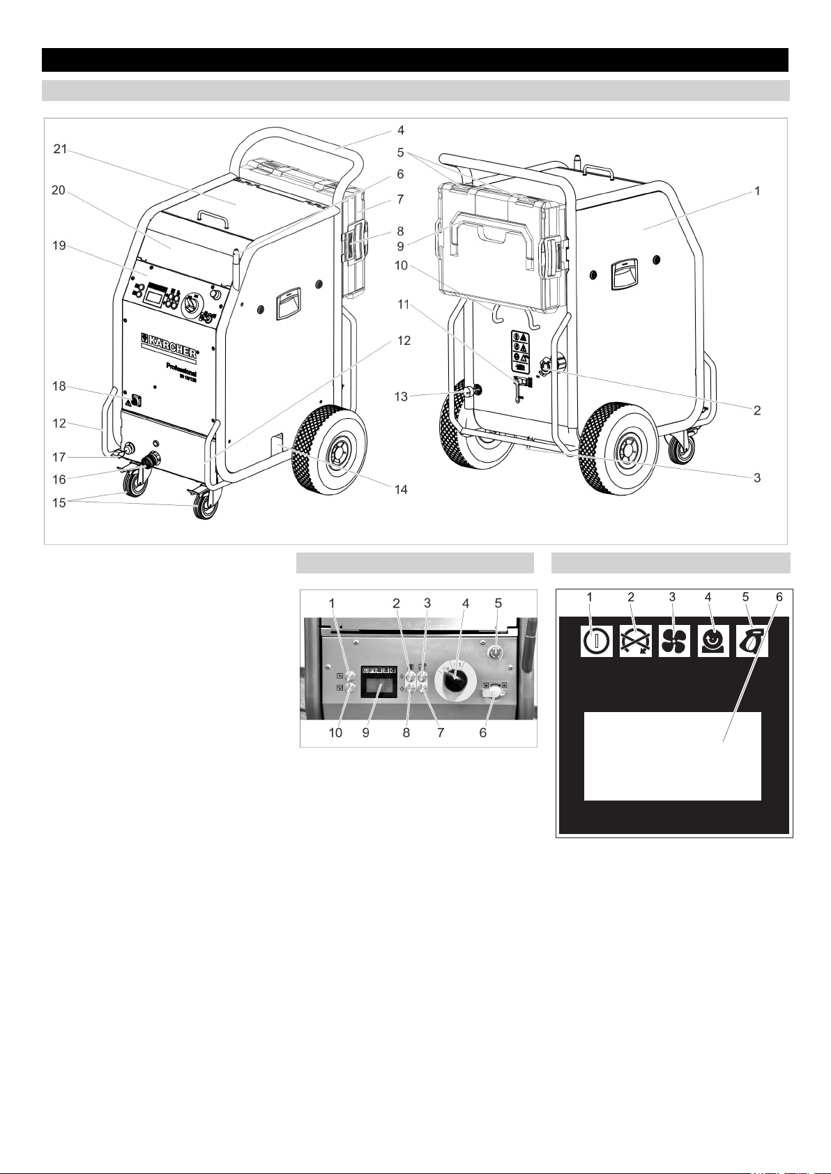
Bedienelemente
Gerät
1 Sicherung F1, unter der Seitenverklei-
dung
2 Druckluft-Anschluss
3 Kondensatablass
4 Schubbügel
5 Verschluss, Koffer
6 Halter für Strahlpistole
7 Koffer für Zubehör
8 Entriegelung, Kofferbefestigung
9 Tragegriff, Koffer
10 Kabelhalter
11 Druckentlastungsventil, Kondensat-
Entleerung des Wasserabscheiders
12 Transportgriff, Rammschutzbügel
13 Netzkabel mit Netzstecker
14 Trockeneis-Auslass, zur Behälter-Ent-
leerung
15 Lenkrolle mit Feststellbremse
16 Kupplung Strahlmittel-Schlauch
17 Erdungsseil mit Klemme
18 Kupplung Steuerleitung
19 Bedienfeld
20 Ablagefach für Zubehör
21 Deckel Trockeneisbehälter
Bedienfeld Display
1 Taste Statistik, Zähler zurücksetzen
2 Taste Strahldruck erhöhen
3 Taste Trockeneis-Dosierung erhöhen
4 Geräteschalter
5 Not-Aus-Taster
6 Schlüsselschalter
7 Taste Trockeneis-Dosierung verringern
8 Taste Strahldruck verringern
9 Display
10 Taste Entleerung Trockeneisbehälter
1 Kontrollleuchte Steuerspannung
grün: Steuerspannung in Ordnung
rot: Steuerspannung zu niedrig
gelb: Entleerung Trockeneisbehälter
aktiv
2 Kontrollleuchte Not-Aus
rot: Not-Aus-Taster betätigt
grün: Not-Aus-Taster nicht betätigt
3 Kontrollleuchte Druckluft
grün: Druck in Ordnung
orange: gewählter Strahldruck nicht er-
reicht
rot: Druck zu gering (unter 0,15 MPa/
1,5 bar)
4 Kontrollleuchte Dosiereinrichtung
grün: Antrieb in Ordnung
rot: Störung im Antrieb
- 3
5DE
Page 6
5 Kontrollleuchte Strahlpistole
grün: Strahlpistole in Ordnung
orange: Abzugshebel der Strahlpistole
während dem Einschalten betätigt
rot: Strahlpistole ausgesteckt oder
Steuerleitung beschädigt
6 Anzeigefeld
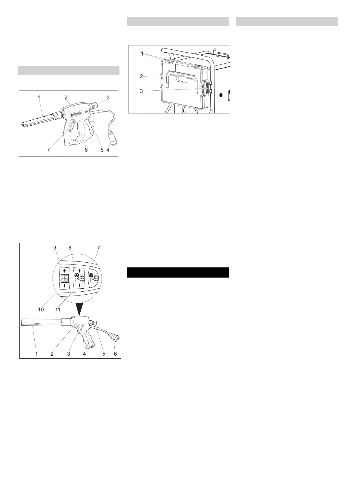
Strahleinrichtung
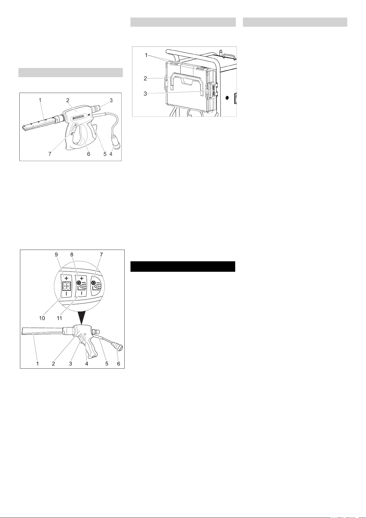
Strahlpistole
1 Düse
2 Strahlpistole
3 Kupplung Strahlmittel-Schlauch
4 Kupplung Steuerleitung
5 Sicherungshebel
6 Abzugshebel
7 Betriebsartschalter
Stellung „1“: Druckluftstrahl
Stellung „2“: Trockeneisstrahl (Druck-
luft und Trockeneispellets)
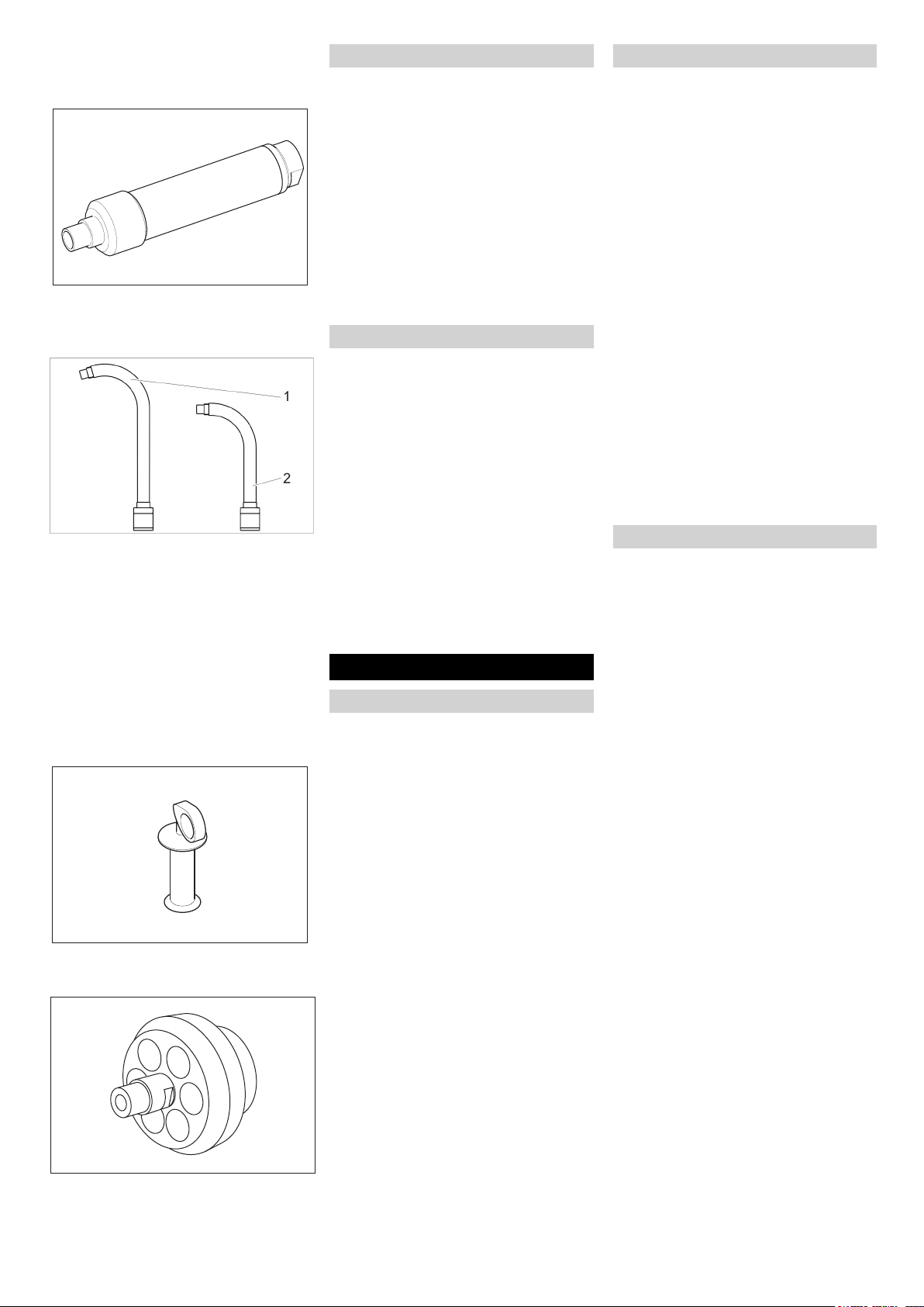
Strahlpistole Advanced (Option)
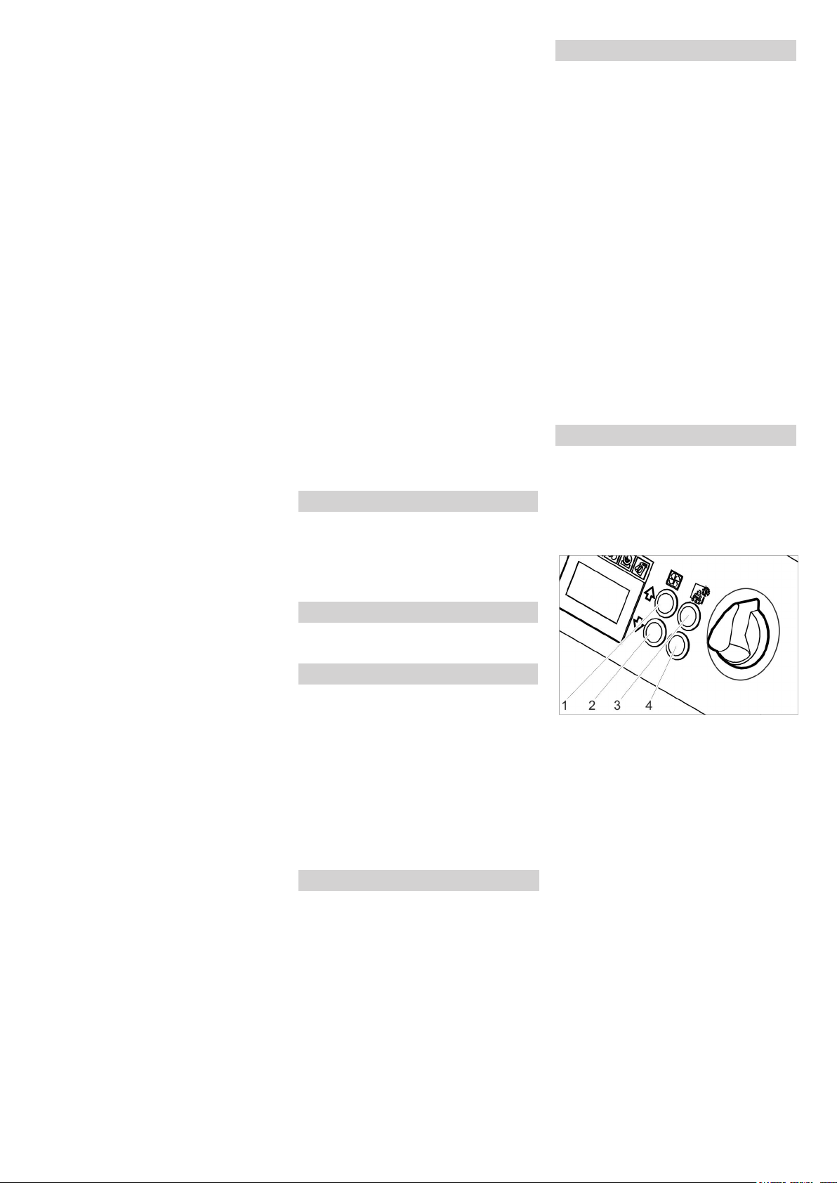
Koffer für Zubehör
Der Koffer dient zur Aufbewahrung der Düsen und zugehörigem Werkzeug.
1 Verschluss
2 Tragegriff
3 Entriegelung
Koffer öffnen
Verschlüsse öffnen.
Deckel nach unten schwenken.
Vorsicht
Beschädigungsgefahr, Keine schweren
Gegenstände auf den geöffneten Deckel
legen.
Koffer vom Gerät trennen.
Entriegelungen drücken und Koffer ab-
nehmen.
Koffer am Gerät anbringen.
Koffer mit den Verschlüssen nach oben
drehen.
Eine Seite des Koffers an die Halterung
setzen und einrasten.
Koffer gegen das Gerät drücken und
gegenüberliegende Halterung einrasten.
Düsen
Hinweis
Die Auswahl der Düse ist abhängig vom
Werkstoff des Reinigungsobjekts und der
Verschmutzung.
Ebenso hat das zur Verfügung stehende
Luftvolumen einen maßgeblichen Einfluss
auf die Düsenwahl.
Alle Düsen werden ohne Werkzeug auf das
Gewinde der Strahlpistole aufgeschraubt.
Die an der Düse angebrachten Schlüsselflächen dienen zum Lösen festsitzender
Düsen mit einem Gabelschlüssel.
Vorsicht
Gefahr von Kaltverschweißung. Düsengewinde vor der Montage mit dem beiliegenden Fett bestreichen.
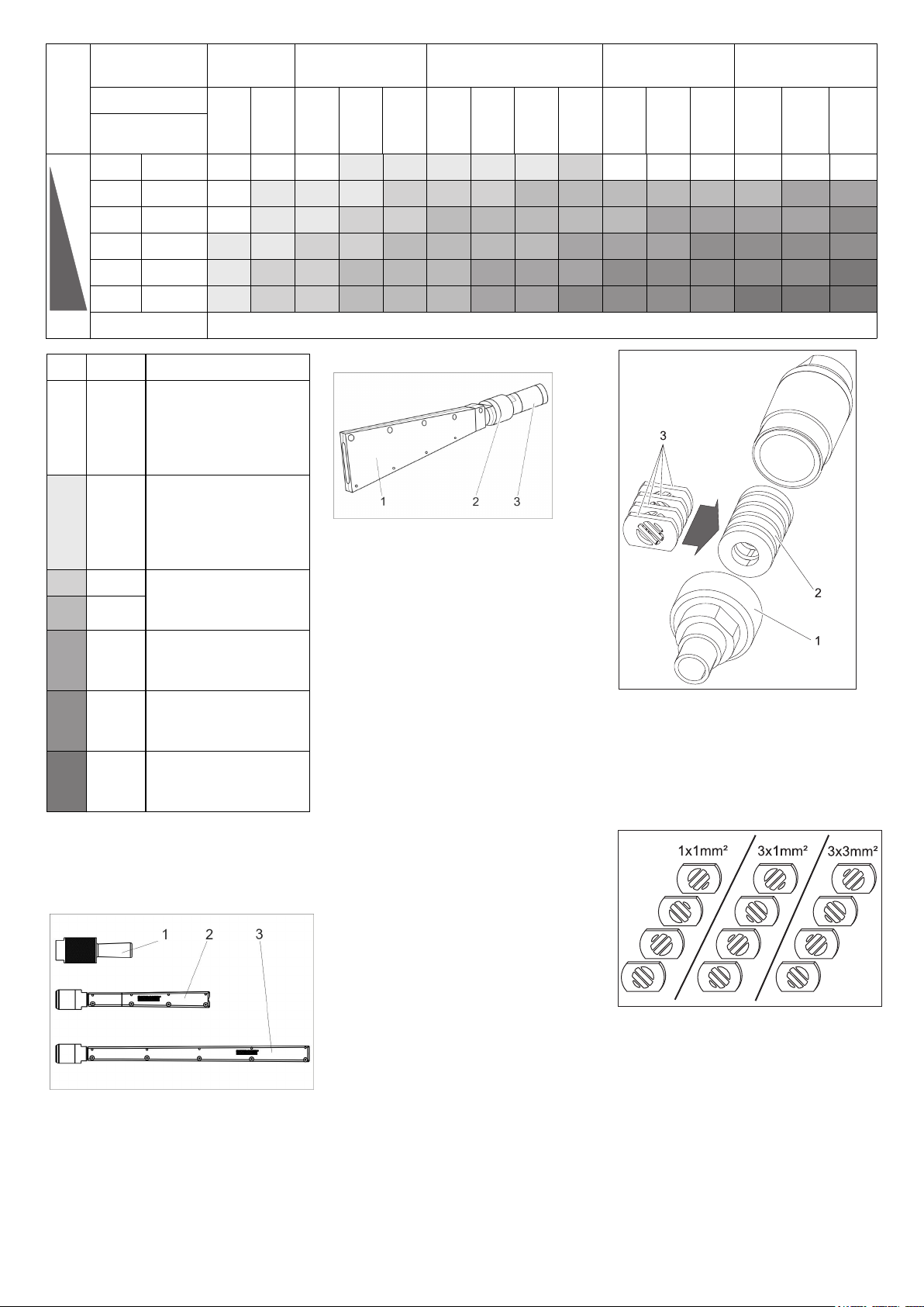
Düsenauswahl
Die nachfolgende Tabelle zeigt den Luftverbrauch bei unterschiedlichen Düsen.
Jede Düse ist mit Luftmengenindex XS XXL gekennzeichnet.
Mit der Düsentabelle kann somit für jede
Düse der Luftverbrauch ermittelt werden.
1 Düse
2 Strahlpistole
3 Abzugshebel
4 Sicherungsknopf
5 Kupplung Strahlmittel-Schlauch
6 Kupplung Steuerleitung
7 Taste Trockeneis-Dosierung Ein/Aus
Leuchtet rot bei ausgeschalteter Tro-
ckeneis-Dosierung
8 Taste Trockeneis-Dosierung erhöhen
9 Taste Strahldruck erhöhen
10 Taste Strahldruck verringern
11 Taste Trockeneis-Dosierung verringern
Inbetriebnahme
Gefahr
Verletzungsgefahr durch herumfliegende
Trockeneispellets.
Beim Vorbereiten des Gerätes alle Baugruppen, insbesondere den StrahlmittelSchlauch auf ordnungsgemäßen Zustand
untersuchen. Beschädigte Baugruppen
durch einwandfreie ersetzen.
Verschmutzte Baugruppen reinigen und
auf ordnungsgemäße Funktion prüfen.
Gerät auf einer waagrechten, ebenen
Fläche abstellen und Feststellbremsen
der Lenkrollen blockieren.
Hinweis:
Zum Schutz vor Abnützung und Verschmutzung kann der Strahlmittelschlauch
mit einem Schutzschlauch überzogen werden. Bei Bedarf Schutzschlauch vor dem
Anschließen über den Strahlschlauch
schieben.
Strahlmittelschlauch mit dem Gerät ver-
binden und sichern.
Strahlpistole mit dem Strahlmittel-
Schlauch verbinden und sichern.
Steuerleitung mit dem Gerät verbinden.
Steuerleitung mit der Strahlpistole ver-
binden.
6 DE
- 4
Page 7
Strahlagressivi-
sehr gering gering mittel hoch sehr hoch
tät
Druck (bar) 2 3 4 5 6 7 8 9 10 11 12 13 14 15 16
Düsengröße
Flächenleistung
XS Ø5 mm 0,40 0,70 0,90
S Ø6 mm 0,70
M Ø7 mm 0,93
L Ø8 mm
XL Ø9 mm
XXL Ø10 mm
1,05 1,45 1,80 2,07 2,40 2,78 3,14 3,48 3,78 4,13 4,35 4,70 5,10 5,40
1,38 1,85 2,28 2,64 3,05 3,63 4,03 4,57 4,80 5,30 5,80 6,22 6,65 7,15
1,09 1,64 2,26 2,78 3,20 3,79 4,40 4,95 5,45 5,90 6,40 7,15 7,67 8,15 8,80
1,50 2,16 2,88 3,50 4,03 4,60 5,41 6,01 6,53 7,27 8,08 8,70 9,28 9,80 10,40
1,52 2,20 2,97 3,66 4,27 5,00 5,82 6,52 7,40 8,00 8,90 9,50 10,05 10,70 11,30
Luftverbrauch in m
1,10 1,30 1,60 1,80 2,00 2,30 -- -- -- -- -- --
3
/min
m3/min
...1 Industrielles Haus-
Druckluftnetz
Einsteiger Kompressor
z. B. Käser M 17,
Compair C 14
1...2 Industrielles HausDruckluftnetz
kleiner Kompressor
z. B. Käser M 31,
Compair C 20GS
2...3 mittlerer Kompressor
3...5
z. B. Käser M 57,
Compair C 35
5...7 mittlerer Kompressor
z. B. Käser M 80,
Compair C 55
7...10 großer Kompressor
z. B. Käser M 122,
Compair C 105
10... sehr großer Kompressor
z. B. Käser M 250,
Compair C 200
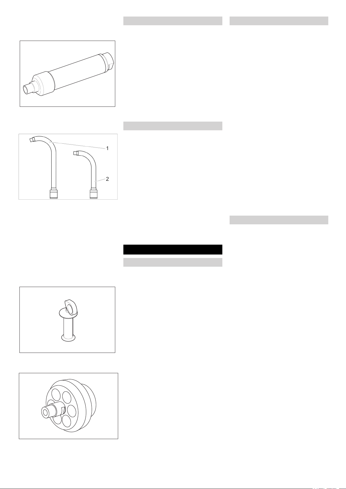
Rundstrahldüse
Neben der mitgelieferten Rundstrahldüse
stehen weitere Rundstrahldüsen mit verschiedenen Querschnitten als Zubehör zur
Verfügung.
Flachstrahldüse
1 Diffusor
2 Überwurfmutter
3 Düseneinsatz
Die Flachstrahldüse besteht aus Düseneinsatz und Diffusor. Als Zubehör stehen Düseneinsätze mit verschiedenem
Querschnitt zur Verfügung.
Düseneinsatz auf den Gewindestutzen
der Strahlpistole aufsetzen und von
Hand festziehen.
Diffusor auf den Düsenaufsatz aufset-
zen.
Diffusor so drehen, dass der Flach-
strahl die gewünschte Ausrichtung zur
Strahlpistole einnimmt.
Überwurfmutter von Hand festziehen.
Scrambler (Zubehör)
Der Scrambler zerkleinert die Trockeneispellets und wird zwischen Strahlpistole und
Düse montiert.
Die Ausrichtung der 4 Lochplatten im
Scrambler gibt den Grad der Zerkleinerung
vor.
Grad der Zerkleinerung auswählen:
1 Verschraubung
2 Magazin
3 Lochplatte
Verschraubung abschrauben.
Magazin mit Lochplatten herausneh-
men.
1 Rundstrahldüse, kurz
2 Rundstrahldüse, lang
3 Rundstrahldüse, extra lang
Rundstrahldüse auf den Gewindestut-
zen der Strahlpistole aufsetzen und von
Hand festziehen.
- 5
Lochplatten wie oben gezeigt im Maga-
zin anordnen (3 Möglichkeiten). Die
Maßangabe im Bild bezieht sich auf die
Größe der Durchlassöffnungen.
Magazin mit Lochplatten in den Scram-
bler einsetzen.
Verschraubung aufschrauben und fest-
ziehen.
7DE
Page 8
Düsenverlängerung (Zubehör)
Zwischen Strahlpistole und Düse kann eine
Verlängerung eingesetzt werden.
Winkelstrahlrohr (Zubehör)
Ein Winkelstrahlrohr wird zwischen Strahlpistole und Düse eingesetzt.
1 Winkelstrahlrohr 105°
2 Winkelstrahlrohr 90°
몇 Warnung
Verletzungsgefahr. Bei Verwendung des
Winkelstrahlrohrs wirkt zusätzlich zur
Rückstoßkraft ein Drehmoment auf die
Strahlpistole. Strahlpistole gut festhalten.
Arbeit mit geringem Strahldruck beginnen
und Strahldruck gegebenenfalls steigern.
Handgriff (Zubehör)
Der Handgriff kann an der Verlängerung
befestigt werden.
Arbeitsbeleuchtung (Zubehör)
(nur bei Advanced Strahlpistole)
Die Arbeitsbeleuchtung wird zwischen
Strahlpistole und Düse angebracht. Das
Ein- und Ausschalten ist in Kapitel „Bedienung/Grundeinstellungen“ beschrieben.
Druckluft anschließen
Hinweis
Für einen störungsfreien Betrieb muss die
Druckluft einen niedrigen Feuchtigkeitsgehalt aufweisen. Die Druckluft muss frei von
Öl, Schmutz und Fremdkörpern sein.
Der Kompressor muss mindestens mit
Nachkühler, Öl- und Wasserabscheider
ausgerüstet sein.
Druckentlastungsventil schließen.
Druckluft-Zuleitung an den Druckluft-
Anschluss des Gerätes anschließen.
Der maximal zulässige Versorgungs-
druck von 1,6MPa (16 bar) darf nicht
überschritten werden.
Netzanschluss herstellen
Gefahr
Gefahr durch elektrischen Schlag.
Die verwendete Steckdose muss von einem Elektroinstallateur installiert sein und
IEC 60364-1 entsprechen.
Das Gerät muss durch einen FI-Schutzschalter Typ B, 30 mA abgesichert sein.
Netzanschlussleitung des Gerätes vor jedem Betrieb auf Beschädigung prüfen. Gerät mit beschädigtem Kabel nicht in Betrieb
nehmen. Beschädigtes Kabel durch Elektrofachkraft austauschen lassen.
Das Verlängerungskabel muss einen IPX4Schutz sicherstellen und die Kabelausführung muss mindestens H 07 RN-F 3G1,5
entsprechen.
Netzstecker in Steckdose stecken.
Bedienung
Trockeneis einfüllen
Gefahr
Gefahr von Kälteverbrennungen. Trockeneis hat eine Temperatur von -79 °C. Trockeneis und kalte Geräteteile nie
ungeschützt berühren. Schutzhandschuhe
und Schutzkleidung tragen.
Deckel Trockeneisbehälter öffnen.
Trockeneisbehälter auf Fremdkörper
und Kondensat prüfen, Fremdkörper
und Kondensat entfernen.
Trockeneispellets in den Behälter fül-
len.
Vorsicht
Beschädigungsgefahr für das Gerät. Als
Strahlmittel dürfen nur Trockeneispellets
verwendet werden. Die Verwendung anderer Strahlmittel führt zum Verlust der Garantie.
Deckel Trockeneisbehälter schließen.
Hinweis
Um Störungen durch verklumpte Trockeneispellets zu vermeiden, ist es sinnvoll den
Inhalt des Trockeneisbehälters ganz zu
verbrauchen, bevor neues Trockeneis eingefüllt wird. Vor längeren Arbeitsunterbrechungen Gerät betreiben, bis der
Trockeneisbehälter leer ist oder den Behälter durch die Funktion Trockeneis Entleerung leeren.
Einstellungen
Hinweis
Die Einstellungen sind abhängig vom
Werkstoff des Reinigungsobjekts und der
Verschmutzung.
Not-Aus-Taster durch Drehen entrie-
geln.
Geräteschalter auf „I“ stellen.
Schlüsselschalter im Uhrzeigersinn
drehen.
Strahldruck mit den Tasten Strahldruck
erhöhen/verringern einstellen.
Hinweis
Je höher der eingestellte Strahldruck ist,
umso höher (aggressiver) ist die Reinigungswirkung.
Trockeneisdosierung mit den Tasten
Trockeneisdosierung erhöhen/verringern einstellen.
Schlüsselschalter gegen den Uhrzei-
gersinn drehen und Schlüssel abziehen.
Durch das automatische Verschließen
des Schlüssellochs wird Verschmutzung während des Betriebs verhindert.
Bei abgezogenem Schlüssel ist das
Gerät gegen Verstellung der Einstellungen und Rückstellen der Statistikwerte
gesichert.
Betrieb
Wartungsarbeiten „täglich vor Betriebs-
beginn“ ausführen (siehe Abschnitt
„Wartung und Pflege“).
Gefahr
Verletzungsgefahr durch herumfliegende
Trockeneispellets. Strahlpistole nicht auf
Personen richten. Dritte Personen vom
Einsatzort entfernen und während des Betriebs fernhalten (z.B. durch Absperrung).
Während des Betriebs nicht an die Düsenöffnung oder in den Trockeneisstrahl fassen.
Vor dem Trennen der Verbindung zwischen Strahlpistole und StrahlmittelSchlauch und zwischen StrahlmittelSchlauch und Gerät unbedingt Druckluftversorgung absperren, Gerät drucklos
machen und Netzstecker aus der Steckdose ziehen.
Arbeitsbereich absperren um den Zu-
tritt von Personen während des Betriebs zu verhindern.
Gefahr
Erstickungsgefahr durch Kohlendioxid. Die
Trockeneispellets bestehen aus festem
Kohlendioxid. Beim Betrieb des Gerätes
steigt der Kohlendioxidgehalt der Luft am
Arbeitsplatz. Arbeitsplatz ausreichend lüften, ggf. ein Personenwarngerät oder
Atemschutzgeräte verwenden.
Anzeichen hoher Kohlendioxidkonzentration in der Atemluft:
– 3...5%: Kopfschmerzen, hohe Atemfre-
quenz.
– 7...10%: Kopfschmerzen, Brechreiz,
evtl. Bewusstlosigkeit.
8 DE
- 6
Page 9
Beim Auftreten dieser Anzeichen sofort
Gerät abstellen und an die frische Luft gehen, vor Fortsetzung der Arbeit Lüftungsmaßnahmen verbessern oder Atemgerät
verwenden.
Kohlendioxid sammelt sich an tiefer gelegenen Stellen. Ansammlung durch aktive
Lüftungsmaßnahmen verhindern.
Sicherheitsdatenblatt des Trockeneisherstellers beachten.
Gefahr
Gefahr durch gesundheitsgefährdende
Stoffe. Können bei der Bearbeitung gesundheitsgefährdende Stäube entstehen,
müssen vor Beginn der Arbeiten entsprechende Sicherheitsmaßnahmen getroffen
werden.
Gefahr
Explosionsgefahr!
Nicht gleichzeitig Leichtmetalle und eisenhaltige Teile bearbeiten.
Werden abwechselnd Leichtmetalle und eisenhaltige Teile bearbeitet, muss der Arbeitsraum und die Absaugeinrichtung vor
der Bearbeitung des jeweils anderen Materials gereinigt werden.
Gefahr durch Staubexplosion. Entstehen
beim Arbeiten brennbare Stäube, müssen
Staubansammlungen vermieden werden.
Staub regelmäßig entfernen bevor sich kritische Mengen angesammelt haben.
Beim Arbeiten in engen Räumen für
ausreichenden Luftwechsel sorgen um
die Kohlendioxidkonzentration in der
Raumluft unter dem gefährlichen Wert
zu halten.
Reinigungsobjekt gegebenenfalls fixie-
ren.
Gefahr
Verletzungsgefahr durch elektrostatische
Entladungen, Beschädigungsgefahr für
elektronische Baugruppen. Beim Reinigungsvorgang kann sich das Reinigungsobjekt elektrisch aufladen.
Reinigungsobjekt elektrisch erden und Erdung während des gesamten Reinigungsvorgangs aufrecht erhalten.
몇 Warnung
Verletzungsgefahr durch Stolpern.
Strahlmittelschlauch und Steuerleitung so
verlegen, dass während der Arbeit keine
Stolpergefahr besteht.
Vorsicht
Beschädigungsgefahr durch in den Trockeneisbehälter fallende Fremdkörper.
Während des Betriebs Deckel des Trockeneisbehälters geschlossen halten.
Erdungsseil elektrisch leitend mit dem
Reinigungsobjekt verbinden oder Reinigungsobjekt auf eine andere Art erden.
Schutzkleidung, Schutzhandschuhe,
dicht schließende Schutzbrille und Gehörschutz tragen.
Druckluftversorgung aktivieren.
Not-Aus-Taster durch Drehen entrie-
geln.
Betriebsart Druckluftstrahl „1“ oder Tro-
ckeneisstrahl „2“ am Betriebsartenschalter der Strahlpistole einstellen.
Sicheren Standplatz wählen und eine
sichere Körperhaltung einnehmen, um
von der Rückstoßkraft der Strahlpistole
nicht aus dem Gleichgewicht zu kommen.
Um das schlagartige Einsetzen des
Rückstoßes zu verhindern, kann ein
langsames Ansteigen des Strahldrucks
eingestellt werden (siehe „Bedienung/
Grundeinstellungen“ Menüpunkt Softstart).
Sicherungsknopf der Strahlpistole ein-
drücken.
Trockeneisstrahl durch Betätigen des
Abzugshebels der Strahlpistole aktivieren und Reinigungsvorgang durchführen.
Hinweis
Bei Verwendung der Advanced Strahlpistole kann die Zudosierung von Trockeneispellets mit der Taste Trockeneis Dosierung Aus/Ein an der Strahlpistole
aus- und einsgeschaltet werden. Bei ausgeschalteter Dosierung leuchtet die Taste
rot, im Display wird „Ice off“ angezeigt.
Zusätzlich kann bei Verwendung der Advanced Strahlpistole der Strahldruck und
die Trockeneismenge an der Strahlpistole
verstellt werden.
Vorsicht
Beschädigungsgefahr für die Dosiereinrichtung durch Schmutz. Beim Strahlbetrieb den Deckel des Trockeneisbehälters
geschlossen lassen, um das Eindringen
von abgestrahlten Verschmutzungen zu
verhindern.
Ausschalten im Notfall
Abzugshebel der Strahlpistole loslas-
sen.
Not-Aus-Taster drücken.
Die Trockeneisdosierung wird gestoppt
und der Luftstrom aus der Düse wird unterbrochen.
Druckluftversorgung unterbrechen.
Inbetriebnahme nach Not-Aus
Not-Aus-Taster durch Drehen entrie-
geln.
Betrieb unterbrechen
Abzugshebel der Strahlpistole loslas-
sen.
Bei Betriebspausen kann die Strahlpis-
tole auf den Halter am Gerät gesteckt
werden.
Hinweis
Bei längerem Betriebsunterbrechungen
können die Trockeneispellets im Trockeneisbehälter verklumpen. Betrieb möglichst
nicht länger als 20 Minuten unterbrechen.
Bei längeren Unterbrechungen Trockeneisbehälter entleeren.
Kondensat ablassen
Ein Wasserabscheider reinigt die dem Gerät zugeführte Druckluft. Dadurch sammelt
sich Kondensat im Wasserabscheider, das
von Zeit zu Zeit entleert werden muss.
Auffangbehälter unter den Kondensa-
tablass stellen.
Druckentlastungsventil langsam öffnen
und warten, bis das Kondensat aus
dem Gerät entwichen ist.
Hinweis
Zum Schutz der Umwelt Kondensat bitte
umweltgerecht entsorgen.
Statistik-Funktion
Werte abrufen
Geräteschalter auf „I“ stellen.
Taste Statistik kurz drücken, die Be-
triebsdauer wird angezeigt.
t: Betriebsdauer seit dem letzten Zu-
rücksetzen.
T: Gesamtbetriebsdauer.
Taste Statistik kurz drücken, die verar-
beitete Trockeneismenge wird angezeigt.
m: Trockeneismenge seit dem letzten
Zurücksetzen.
M: Trockeneismenge gesamt.
Taste Statistik kurz drücken, der durch-
schnittliche Trockeneisverbrauch wird
angezeigt.
q: Durchschnittlicher Trockeneisverbrauch seit dem letzten Zurücksetzen.
Q: Durchschnittlicher Trockeneisverbrauch gesamt.
Werte zurücksetzen
Schlüsselschalter im Uhrzeigersinn
drehen.
Taste Statistik 4 Sekunden lang drü-
cken.
Hinweis
Die Gesamtwerte können nicht gelöscht
werden.
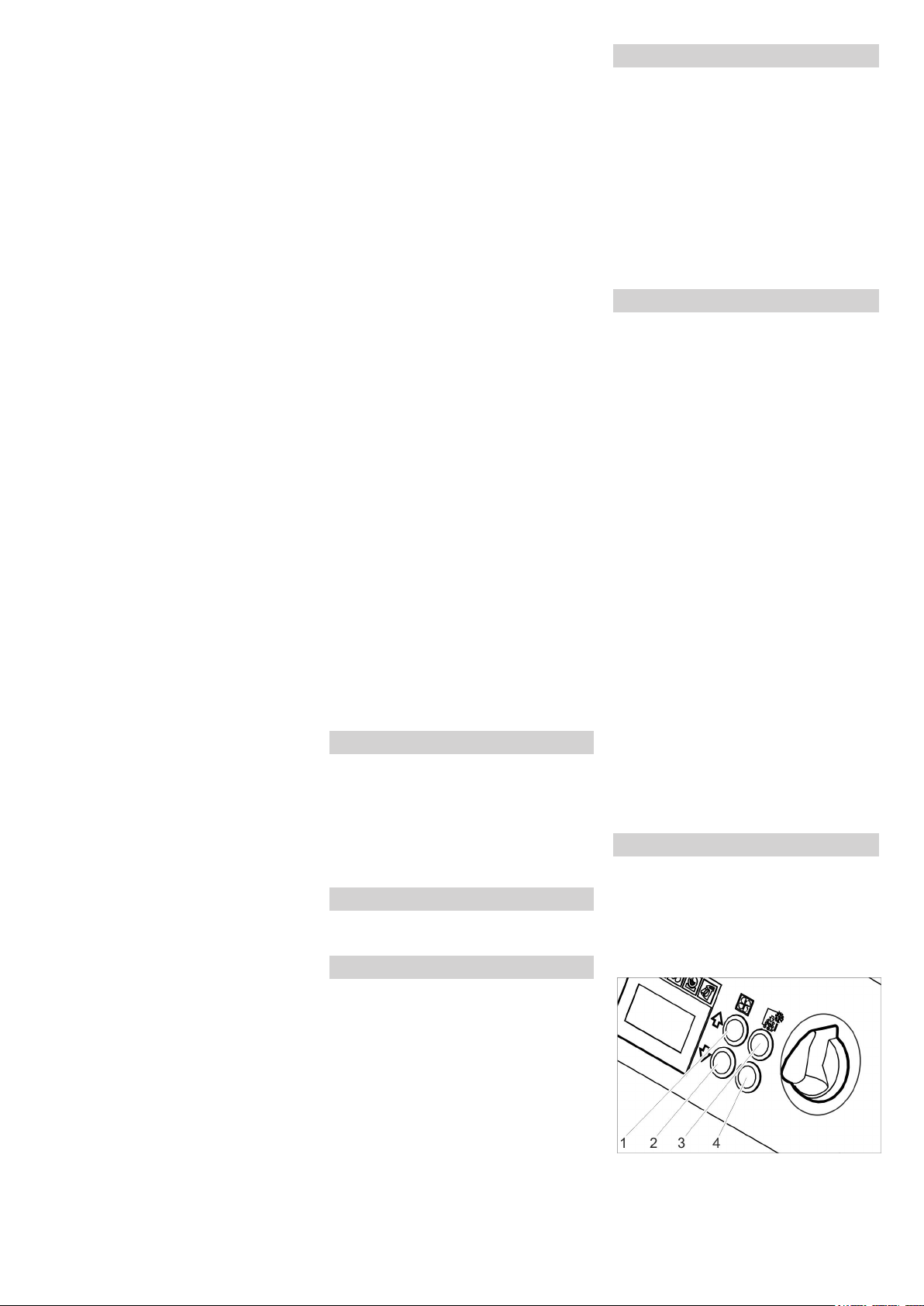
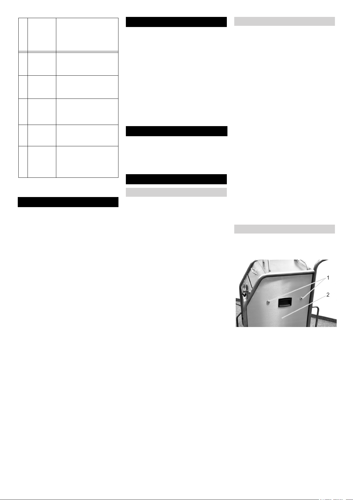
Grundeinstellungen
Tasten Strahldruck erhöhen und Strahl-
druck verringern gleichzeitig drücken
und festhalten, Schlüsselschalter im
Uhrzeigersinn drehen.
In der Betriebsart Grundeinstellungen haben die Tasten folgende Funktionen:
1 Wert erhöhen
2 Wert verringern
3 Menüpunkt nach oben
4 Menüpunkt nach unten
- 7
9DE
Page 10
Einstellbereich
Menüpunkt
0, 1, 2, 3,
4, 5 Sekunden
Softstart
1, 2, 3, 4, 5
Minuten
T_Dump
metric, imperial
Language
ON/OFF Düsenbeleuchtung (Opti-
Lighting
ON/OFF Demonstrationsbetrieb:
Demo-Mode
Grundeinstellungen beenden
Schlüsselschalter gegen den Uhrzei-
gersinn drehen.
Beschreibung
Sanftanlauf, Dauer bis
zum Erreichen des gewählten Strahldrucks
Dauer des TrockeneisEntleerungsvorgangs
Maßeinheiten
metric: kg/h, MPa
imperial: lbs, psi
on) ein-/ausschalten
Bedienung wird simuliert,
Druckluft- und Trockeneisabgabe sind gesperrt.
Außerbetriebnahme
Gefahr
Gefahr von Kälteverbrennungen. Trockeneis hat eine Temperatur von -79 °C. Trockeneis und kalte Geräteteile nie
ungeschützt berühren. Schutzhandschuhe
und Schutzkleidung tragen.
Gefahr
Verletzungsgefahr durch herumfliegende
Trockeneispellets. Strahlpistole nicht auf
Personen richten. Dritte Personen vom
Einsatzort entfernen und während des Betriebs fernhalten (z.B. durch Absperrung).
Druckluftversorgung schließen.
Auffangbehälter unter den Kondensa-
tablass stellen.
Druckentlastungsventil langsam öffnen
und warten, bis Kondensat und Druckluft aus dem Gerät entwichen sind.
Auffangbehälter unter den Trockeneis-
Auslass stellen.
Taste Entleerung Trockeneisbehälter
drücken und warten, bis der Trockeneisbehälter leer ist.
Die Trockeneis-Entleerung stoppt nach
der voreingestellten Zeit (siehe „Grundeinstellungen“).
Bei Bedarf Taste Entleerung Trockeneisbehälter mehrmals drücken.
Hinweis
Zum Schutz der Umwelt Kondensat bitte
umweltgerecht entsorgen.
Geräteschalter auf „0/OFF“ stellen.
Gerät von der Druckluft-Zuleitung tren-
nen.
Netzstecker aus Steckdose ziehen.
Erdungsseil reinigen und aufrollen.
Strahlschutt entsprechend den gelten-
den Vorschriften entsorgen.
Transport
Gefahr
Unfallgefahr durch Trockeneisreste im Gerät. Vor dem Transport in geschlossenen
Fahrzeugen muss das Trockeneis restlos
aus dem Gerät entfernt sein um Gefährdungen der mitfahrenden Personen durch
Kohlendioxid zu verhindern.
Vor dem Transport alle Schritte im Ka-
pitel „Außerbetriebnahme“ ausführen.
Gerät auf das Transportfahrzeug brin-
gen.
Bremsen der Lenkrollen arretieren.
Gerät mit Spanngurten auf dem Fahr-
zeug befestigen.
Lagerung
Vorsicht
Verletzungs- und Beschädigungsgefahr!
Gewicht des Gerätes bei Lagerung beachten.
Dieses Gerät darf nur in Innenräumen gelagert werden.
Wartung und Pflege
Wartungshinweise
Grundlage für eine betriebssichere Anlage
ist die regelmäßige Wartung nach folgendem Wartungsplan.
Verwenden Sie ausschließlich Original-Ersatzteile des Herstellers oder von ihm empfohlene Teile, wie
– Ersatz- und Verschleissteile,
– Zubehörteile,
– Betriebsstoffe,
– Reinigungsmittel.
Gefahr!
Unfallgefahr bei Arbeiten am Gerät. Vor Arbeiten am Gerät alle Arbeitsschritte des
Kapitels „Außerbetriebnahme“ durchführen.
Gefahr
Gefahr von Kälteverbrennungen durch Trockeneis oder kalte Geräteteile. Bei Arbeiten
am Gerät geeignete Kälteschutzkleidung
tragen oder Trockeneis entfernen und Gerät aufwärmen lassen.
Gefahr
Gefahr durch volumetrische Ausdehnung
und Kälteverbrennung.
Trockeneis nie in den Mund nehmen.
Vorsicht
Beschädigungsgefahr. Strahlpistole nicht
mit Lösungsmittel, Benzin oder ölhaltigem
Reinigungsmittel reinigen.
Wartungsvertrag
Um einen zuverlässigen Betrieb der Anlage
zu gewährleisten, empfehlen wir Ihnen einen Wartungsvertrag abzuschließen. Wenden Sie sich bitte an Ihren zuständigen
Kärcher-Kundendienst.
Wartungsplan
Täglich vor Betriebsbeginn
Strahlmittelschlauch sorgfältig auf Ris-
se, Knickstellen und andere Beschädigungen untersuchen. Weiche Stellen
im Schlauch zeigen Abnutzung auf der
Innenseite des Schlauches an. Defekten oder abgenützten Schlauch durch
neuen Schlauch ersetzen.
Elektrische Kabel und Stecker auf Be-
schädigung untersuchen. Defekte Teile
vom Kundendienst austauschen lassen.
Alle 100 Betriebsstunden
Kupplungen an Strahlmittel-Schlauch,
am Gerät und an der Strahlpistole auf
Beschädigung und Abnutzung untersuchen. Defekten Schlauch ersetzen, defekte Kupplungen an Gerät oder
Strahlpistole vom Kundendienst ersetzen lassen.
Dosiereinrichtung auf Schäden und Un-
dichtigkeiten untersuchen. Werden
Schäden/Undichtigkeiten festgestellt,
Kundendienst verständigen.
Befestigungskappen der Hinterräder
auf festen Sitz prüfen.
Alle 500 Stunden oder jährlich
Gerät durch Kundendienst prüfen las-
sen.
Alle 2 Jahre
Strahlmittelschlauch mindestens alle
2 Jahre erneuern.
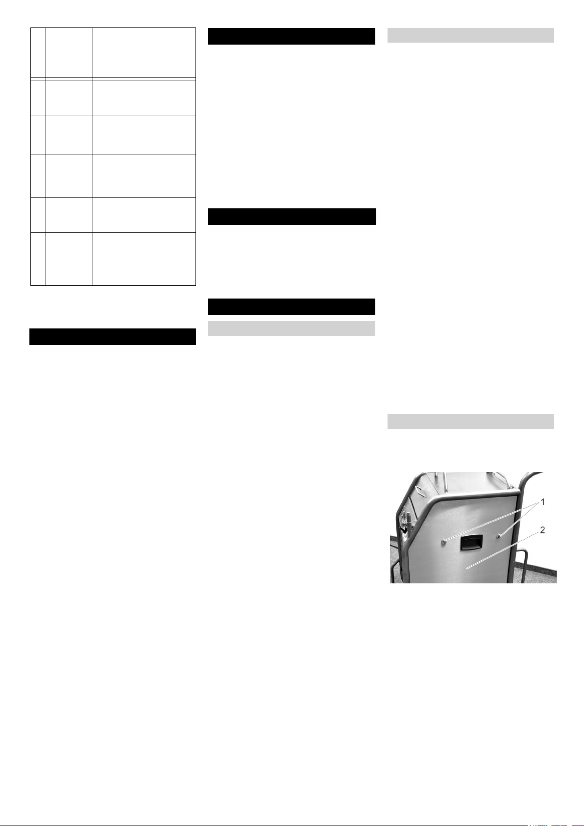
Gerät öffnen
Zur Durchführung einiger Wartungsarbeiten müssen die Seitenverkleidungen des
Gerätes entfernt werden:
1 Schnellverschluss
2 Seitenverkleidung
Schnellverschlüsse gegen den Uhrzei-
gersinn öffnen.
Seitenverkleidung abnehmen.
10 DE
- 8
Page 11
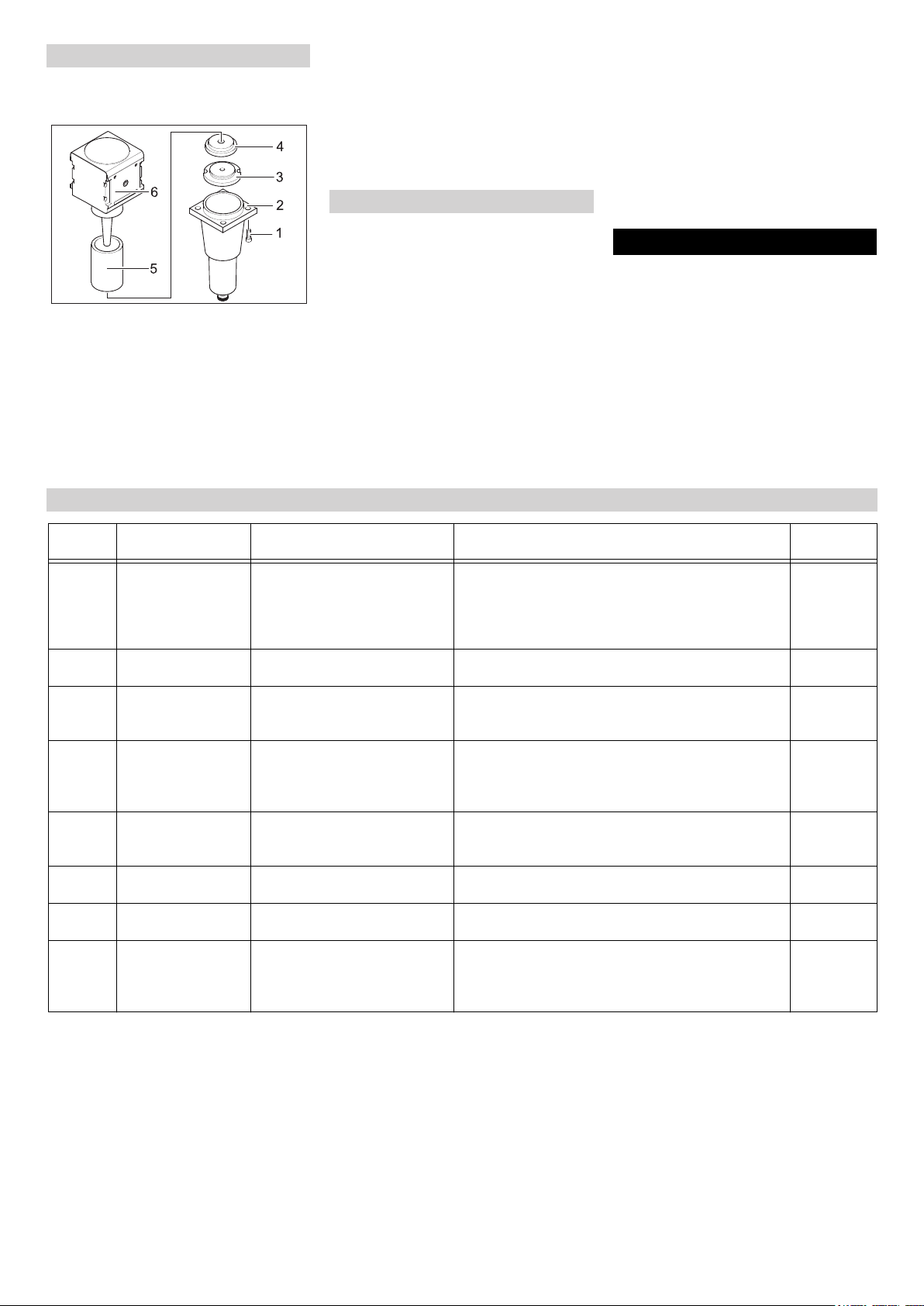
Wartungsarbeiten
Filtereinsatz im Wasserabscheider austauschen
1 Schraube
2 Unterteil
3 Mutter
4 Scheibe
5 Filtereinsatz
6 Oberteil
4 Schrauben herausdrehen.
Unterteil abnehmen.
Mutter abschrauben.
Scheibe abnehmen.
Filtereinsatz abnehmen und durch neu-
en Filtereinsatz ersetzen.
Wasserabscheider in umgekehrter Rei-
henfolge wieder zusammenbauen.
Prüfungen
Nach BGV D 26 müssen am Gerät folgende Prüfungen durch einen Sachkundigen
vorgenommen werden. Die Ergebnisse der
Prüfung müssen in einer Prüfbescheinigung festgehalten werden. Die Prüfbescheinigung muss vom Betreiber des
Gerätes bis zur nächsten Prüfung aufbewahrt werden.
Nach Betriebsunterbrechung von mehr
als einem Jahr
Gerät auf ordnungsgemäße Beschaf-
fenheit und Funktion prüfen.
Nach Änderung des Aufstellungsortes
Gerät auf ordnungsgemäße Beschaf-
fenheit, Funktion und Aufstellung prüfen.
Nach Instandsetzungsarbeiten oder
Veränderungen die die Betriebssicherheit beeinflussen können
Gerät auf ordnungsgemäße Beschaf-
fenheit, Funktion und Aufstellung prüfen.
Hilfe bei Störungen
Gefahr!
Unfallgefahr bei Arbeiten am Gerät. Vor Arbeiten am Gerät alle Arbeitsschritte des
Kapitels „Außerbetriebnahme“ durchführen.
Gefahr
Gefahr von Kälteverbrennungen durch Trockeneis oder kalte Geräteteile. Bei Arbeiten
am Gerät geeignete Kälteschutzkleidung
tragen oder Trockeneis entfernen und Gerät aufwärmen lassen.
Displayanzeige
E001 KL Steuerspannung
E002 KL Not-Aus leuchtet
E003 KL Druckluft leuchtet
E004 KL Dosierung leuch-
E005 KL Strahlpistole
E006 KL Strahlpistole
E007 KL Druckluft leuchtet
E008 KL Strahlpistole
Kontrollleuchte
(KL)
leuchtet rot
rot
rot
tet rot
leuchtet rot
leuchtet rot
rot
leuchtet orange
Störungen mit Anzeige im Display
Mögliche Ursache Behebung Durch wen
Steuerspannung zu niedrig Gerät ausschalten, kurz warten, Gerät wieder ein-
schalten.
Steckdose prüfen lassen.
Bei wiederholtem Auftreten des Fehlercodes, KärcherKundendienst benachrichtigen
Not-Aus-Taster ist gedrückt Not-Aus-Taster durch Drehen entriegeln. Bediener
Druck der Druckluftversorgung
zu gering
Störung in der Dosiereinheit Gerät ausschalten, kurz warten, Gerät wieder ein-
Verbindung zwischen Gerät und
Strahlpistole gestört.
Kurzschluss in Strahlpistole
oder Steuerkabel
Störung am Druckluft-Regelventil
Abzugshebel der Strahlpistole
war während dem Einschalten
oder dem Entriegeln des NotAus-Tasters betätigt
Druck erhöhen.
Gerät ausschalten, kurz warten, Gerät wieder einschalten.
schalten.
Bei wiederholtem Auftreten des Fehlercodes, KärcherKundendienst benachrichtigen
Korrekte Verbindung der Kupplungen in der Steuerleitung prüfen.
Steuerkabel auf Beschädigung untersuchen.
Strahlpistole oder Strahlschlauch mit Steuerkabel ersetzen.
Kundendienst aufsuchen. Bediener
Abzugshebel der Strahlpistole loslassen. Bediener
Bediener
Bediener
Bediener
Bediener
Bediener
- 9
11DE
Page 12

Störungen ohne Anzeige im Display
Störung Mögliche Ursache Behebung Durch wen
Keine Displayanzeige
trotz eingeschaltetem
Hauptschalter
Kein Druckluftstrahl
trotz gezogenem Abzugshebel
Druckluftstrahl zu
schwach
Keine Trockeneispellets im Druckluftstrahl
Netzstecker nicht in die Steckdose eingesteckt.
Sicherung F1 hat ausgelöst Seitenverkleidung abnehmen und Sicherung F1
Druckluftversorgung hat zu wenig Druck Druck kontrollieren. Bediener
Strahldruck zu niedrig eingesellt Strahldruck höher einstellen. Bediener
Spannungsversorgung unterbrochen Spannungsversorgung kontrollieren. Kontroll-
Not-Aus-Taster ist gedrückt Not-Aus Taster durch Drehen entriegeln. Kontroll-
Steuerleitung nicht korrekt angeschlossen Verbindung zwischen Streuerleitung und Strahl-
Steuerleitung ist defekt Strahlmittelschlauch ersetzen. Bediener
Strahldruck zu niedrig eingesellt Strahldruck höher einstellen. Bediener
Druckluftversorgung hat zu wenig Druck oder
Fördermenge des Kompressors zu gering.
Filtereinsatz im Wasserabscheider verstopft. Filtereinsatz im Wasserabscheider ersetzen. Bediener
Strahlmittelschlauch oder Strahlpistole ver-
stopft
Trockeneis-Dosierung ausgeschaltet (nur bei
Strahlpistole Advanced), Taste TrockeneisDosierung Ein/Aus auf der Strahlpistole
leuchtet rot, Displayanzeige „Ice off“.
Trockeneisbehälter leer Trockeneisbehälter füllen Bediener
Trockeneis verschmolzen Trockeneisbehälter entleeren und mit frischen
Rüttler am Trockeneisbehälter arbeitet nicht Kundendienst aufsuchen. Bediener
Antriebsmotor der Dosiereinrichtung überlastet Dosiereinrichtung auftauen lassen Bediener
Druckluftaustritt im Trockeneisbehälter Druckausgleichskanal in der Dosiereinrichtung
Dosierscheibe in der Dosiereinheit defekt Dosierscheibe ersetzen. Kunden-
Netzstecker in eine Steckdose stecken. Bediener
Bediener
durch Drücken entriegeln.
Bediener
leuchte „Gerät ein“ muss grün leuchten.
Bediener
leuchte „Gerät ein“ muss grün leuchten.
Bediener
pistole sowie zwischen Steuerleitung und Gerät
überprüfen.
Druck und Fördermenge kontrollieren. Bediener
Strahlmittelschlauch und Strahlpistole auftauen
lassen und Verstopfung beseitigen. Arbeitsdruck
erhöhen und / oder Trockeneisdosierung reduzieren.
Taste Trockeneis-Dosierung an der Strahlpistole
Advanced drücken.
Trockeneispellets füllen.
reinigen.
Bediener
Bediener
Bediener
Kunden-
dienst
dienst
12 DE
- 10
Page 13

Technische Daten
Elektrischer Anschluss
Spannung V 220...240
Stromart 1~
Frequenz Hz 50
Anschlussleistung kW 0,6
Schutzklasse IPX4
FI-Schutzschalter delta I in A 0,03
Ableitstrom, typ. mA 7,5
Druckluft
Schlauch-Nennweite Zoll 3/4
Versorgungsdruck (max.) MPa (bar) 1,6 (16)
Versorgungsdruck (min.) MPa (bar) 0,2 (2)
3
Druckluftverbrauch m
Druckluftqualität trocken, ölfrei
Leistungsdaten
Strahldruck (max.) MPa (bar) 1,6 (16)
Durchmesser der Trockeneispellets (max.) mm 3
Trockeneisverbrauch kg/h 30...120
Abmessungen Betrieb
Inhalt Trockeneisbehälter kg 40
Breite mm 716
Tiefe mm 850
Höhe mm 1102
Gewicht mit Zubehör kg 101,5
Gewicht, betriebsbereit, mit gefülltem Trockeneisbehälter kg 140
Reifendruck (max.) MPa (bar) 0,2 (2)
Gewicht Strahleinrichtung (Strahlmittelschlauch, Strahlpistole, Werkzeugtasche) kg 10
Rückstoßkraft der Strahlpistole (max.) N 100
Drehmoment der Strahlpistole (max.), nur bei Winkeldüse N 40
Schalldruckpegel L
Schallleistungspegel L
pA
WA
Unsicherheit K dB(A) 5
Gerätevibrationen
Strahlpistole m/s² 1,2
Strahlmittelschlauch m/s² 1,2
/min 2...12
dB(A) 114
dB(A) 136
- 11
13DE
Page 14
Zubehör
Schutzkleidung
Vollsicht-Schutzbrille, antibeschlag, TeileNr.: 6.321-208.0
Kälteschutzhandschuhe mit rutschhemmendem Profil, Kategorie III nach EN 511,
Teile-Nr.: 6.321-210.0
Gehörschutz mit Kopfbügel, Teile-Nr.:
6.321-207.0
Strahleinrichtung
Rundstrahldüse, L, lang
Teile-Nr.: 4.574-019.0
Rundstrahldüse, L, extra lang
Teile-Nr.: 4.574-016.0
Rundstrahldüse, M, lang
Teile-Nr.: 4.574-018.0
Rundstrahldüse, M, kurz
Teile-Nr.: 4.130-418.0
Rundstrahldüse, L, kurz
Teile-Nr.: 4.130-419.0
Flachstrahldüse
Teile-Nr.: 4.130-423.0
Flachstrahldüseneinsatz, M, 6 mm
Teile-Nr.: 4.130-421.0
Flachstrahldüseneinsatz, L, 8mm
Teile-Nr.: 4.130-420.0
Flachstrahldüseneinsatz, XL, 10 mm
Teile-Nr.: 4.130-422.0
Garantie
In jedem Land gelten die von unserer zuständigen Vertriebsgesellschaft herausgegebenen Garantiebedingungen. Etwaige
Störungen an Ihrem Gerät beseitigen wir
innerhalb der Garantiefrist kostenlos, sofern ein Material- oder Herstellungsfehler
die Ursache sein sollte. Im Garantiefall
wenden Sie sich bitte mit Kaufbeleg an Ihren Händler oder die nächste autorisierte
Kundendienststelle.
EG-Konformitätserklärung
Hiermit erklären wir, dass die nachfolgend
bezeichnete Maschine aufgrund ihrer Konzipierung und Bauart sowie in der von uns
in Verkehr gebrachten Ausführung den einschlägigen grundlegenden Sicherheitsund Gesundheitsanforderungen der EGRichtlinien entspricht. Bei einer nicht mit
uns abgestimmten Änderung der Maschine
verliert diese Erklärung ihre Gültigkeit.
Produkt: Trockeneisstrahlgerät
Typ: 1.574-xxx
Einschlägige EG-Richtlinien
2006/42/EG (+2009/127/EG)
2004/108/EG
Angewandte harmonisierte Normen
EN 55014–1: 2006+A1: 2009+A2: 2011
EN 55014–2: 1997+A1: 2001+A2: 2008
EN 60204–1
EN 61000–3–2: 2006+A1: 2009+A2: 2009
EN 61000–3–3: 2008
EN 62233: 2008
Angewandte nationale Normen
GS-RCI-13 (in Anlehnung)
Winkelstrahlrohr 90°
Teile-Nr.: 4.321-203.0
Winkelstrahlrohr 105°
Teile-Nr.: 4.321-204.0
Düsenverlängerung, 300 mm lang
Teile-Nr.: 4.130-417.0
Handgriff
Teile-Nr.: 6.321-206.0
Scrambler
Teile-Nr.: 4.110-015.0
Arbeitsbeleuchtung
Teile-Nr.: 2.815-422.0
Schutzschlauch für Strahlrohr, Kunststoff,
100 m
Teile-Nr.: 6.667-214.0
Die Unterzeichnenden handeln im Auftrag
und mit Vollmacht der Geschäftsführung.
CEO
Dokumentationsbevollmächtigter:
S. Reiser
Alfred Kärcher GmbH & Co. KG
Alfred-Kärcher-Str. 28 - 40
71364 Winnenden (Germany)
Tel.: +49 7195 14-0
Fax: +49 7195 14-2212
Winnenden, 2013/02/01
Head of Approbation
14 DE
- 12
Page 15
Please read and comply with
these original instructions prior
to the initial operation of your appliance and
store them for later use or subsequent owners.
Contents
Environmental protection . . EN . . 1
Safety instructions . . . . . . . EN . . 1
Proper use . . . . . . . . . . . . . EN . . 2
Function . . . . . . . . . . . . . . . EN . . 2
Control elements. . . . . . . . . EN . . 3
Start up . . . . . . . . . . . . . . . . EN . . 4
Operation . . . . . . . . . . . . . . EN . . 6
Shutting down . . . . . . . . . . . EN . . 8
Transport. . . . . . . . . . . . . . . EN . . 8
Storage . . . . . . . . . . . . . . . . EN . . 8
Maintenance and care . . . . EN . . 8
Troubleshooting . . . . . . . . . EN . . 9
Technical specifications . . . EN . 11
Accessories . . . . . . . . . . . . EN . 12
Warranty . . . . . . . . . . . . . . . EN . 12
EC Declaration of Conformity EN . 12
Environmental protection
The packaging material can be recycled. Please do not place the packaging into the ordinary refuse for
disposal, but arrange for the proper
recycling.
Old appliances contain valuable materials that can be recycled; these
should be sent for recycling. Batteries, oil, and similar substances must
not enter the environment. Please
dispose of your old appliances using
appropriate collection systems.
Notes about the ingredients (REACH)
You will find current information about the
ingredients at:
www.kaercher.com/REACH
Safety instructions
The appliance may only be operated by
persons who have read and understood the
contents of this operating instructions manual. Please ensure that you conform to all
the safety instructions and regulations.
This operating instructions manual
must be stored in such a way that it can
be easily accessed by the operator.
Danger or hazard levels
Danger
Immediate danger that can cause severe
injury or even death.
몇 Warning
Possible hazardous situation that could
lead to severe injury or even death.
Caution
Possible hazardous situation that could
lead to mild injury to persons or damage to
property.
Symbols on the machine
Danger
Risk of injury on account of flying dry ice
pellets. Do not direct the jet pistol on persons. Keep third persons away from the
place of use and when the machine is being
operated (by cordoning off the area).
Do not touch/hold the nozzle or the dry ice
jet when the machine is running.
Danger
Risk of suffocation on account of carbon dioxide. The dry ice pellets are made of solidified carbon dioxide. The carbon dioxide
content in the air at the place where the machine is used will increase when the machine is running. Ensure adequate
ventilation at the place of use; if possible,
use an alarm to warn persons. Symptoms
of high levels of carbon dioxide in the air
that is breathed in:
– 3...5%: headache, faster breathing.
– 7...10%: headache, nausea and per-
haps even unconsciousness.
If any of these symptoms occur, please
switch off the machine immediately and get
a breath of fresh air; improve the ventilation
before starting work again with the machine
or use respirators.
Follow the safety specifications of the manufacturer of dry ice.
Danger
Risk of injury on account of electro-static
discharge; risk of damage to the electronic
components. The object being cleaned can
get charged electrically during the cleaning
process. Provide suitable earthing for the
object being cleaned and ensure that the
earthing remains intact during the entire
cleaning process.
Danger
Risk of injury on account of electric shock.
Pull the plug out of the socket before opening the control cabinet.
Danger
Risk of cold burns. Dry ice has a temperature of -79 °C. Never touch dry ice or cold
parts of the machine without appropriate
protection.
Danger
Risk of injury on account of flying dry ice
pellets or dirt particles. Wear close fitting
safety goggles.
Risk of hearing impairment. Wear ear-protection aids.
The protective equipment may not prevent
visual contact and the communication with
the work environment.
Danger
Risk of injury on account of flying dry ice
pellets or dirt particles.
Risk of injury when touching cold appliance
parts.
Wear protective gloves and long-sleeved
protective overalls as per EN 511.
General notes on safety
Danger
Risk of injury if the machine is left running
in an unattended state. Disconnect the
mains plug from the socket before performing any work.
Danger
Risk of injury on account of electric shock.
Pull the plug out of the socket before opening the control cabinet.
Danger
Risk of cold burns on account of dry ice or
cold parts of the machine. While working on
the machine, wear appropriate safety gear
for protection against cold or remove dry
ice and let the machine heat up.
Danger
Danger arising from volumetric expansion
and cryogenic burn.
Never put dry ice in your mouth.
몇 Warning
Risk of injury on account of the recoil force
of the jet pistol. Ensure that you are standing at a safe place and hold the jet pistol
properly in your hand before pressing the
trigger of the jet pistol.
- 1
15EN
Page 16

Danger
Risk of injury on account of flying objects.
Fix light cleaning objects properly to prevent them from being dragged off with the
dry ice jet.
몇 Warning
Danger of crushing on account of the dosing equipment. Always remove the machine plug from the socket before removing
the protective shield of the dry ice container.
Specifications and Guidelines
For the operation of this system the following regulations and directives are applicable in the Federal Republic of Germany
(available from Carl Heymanns Verlag KG,
Luxemburger Straße 449, 50939 Cologne):
– BGV D 26 Spray jet tasks
– Executing instructions for BGV D 26
– BGR 117 Working in closed rooms
– BGR 139 safety rules for persons -
emergency signal systems.
– BGR 189 Using safety gear
– BGR 195 Using of safety gloves
– BGR 500 use of work equipment
– BGI 534 Working in closed rooms
– BGI 836 Gas warner
Observe national safety provisions and
safety instructions as well as national provisions of occupational health and safety
agencies and trade associations!
Safety Devices
Function
The air pressure reaches the jet pistol via a
pressure regulation valve. The valve opens
when the trigger of the jet pistol is pressed
and the air flow comes out from the jet pistol. Additionally, dry ice pellets are dosed
into the air jet via the dosing device. The
additional dosing can be switched off by
means of the operating mode switch. The
dry ice pellets hit the surface to be cleaned
and remove the dirt. Additional thermal
stress occurs between the dirt and the object to be cleaned due to the -79 °C cold dry
ice pellets; this contributes to the removal
of the dirt. At the same time, dry ice immediately gets coverted into gaseous carbon
dioxide on contact and requires 700 times
the volume of dry ice. Thus, the dirt penetrated by the dry ice thus gets thrown off.
During the spraying operation through the
jet, a vibrator located on the dry ice container ensures continuous sliding of the dry ice
pellets.
Emergency-stop button
If the emergency stop button is pressed,
the dry ice dosing is stopped and the air
flow from the nozzle is interrupted.
Switch-off in case of emergency
Release the trigger of the jet pistol.
Press emergency-stop button.
The dry ice dosing is topped and the air
flow from the nozzle is interrupted.
Interrupt the compressed air supply.
Proper use
The machine is used to remove dirt using
dry ice pellets that are speeded up using an
air jet.
The machine should not be operated in explosive environments.
Use only dry ice pellets as jet medium. Using any other jet medium can cause damage to the machine.
16 EN
- 2
Page 17
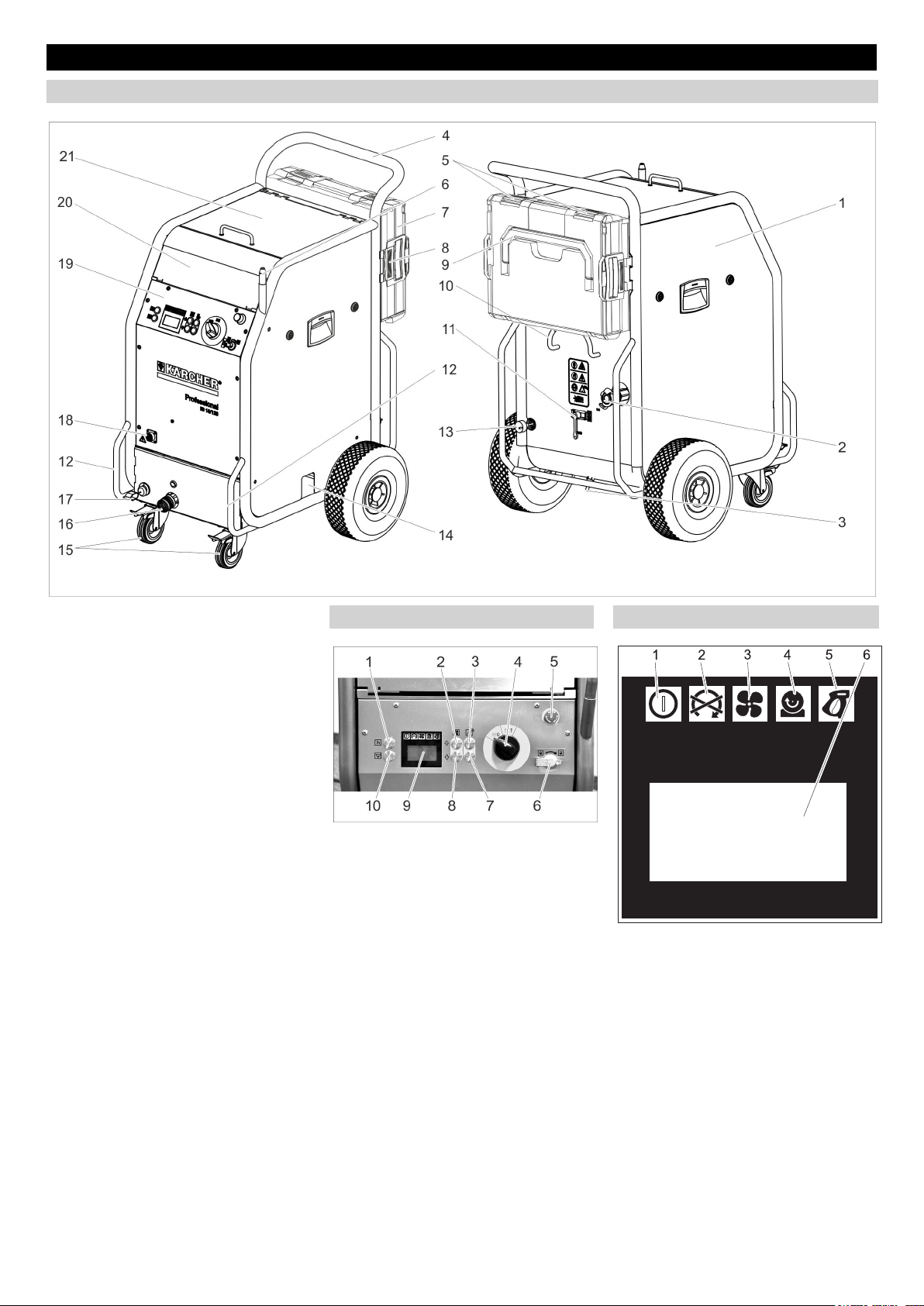
Control elements
Device
1 Fuse F1, below the side panel
2 Compressed air connection
3 Condensate drain-out
4 Push handle
5 Closure, case
6 Holder for jet pistol
7 Case for accessories
8 Unlocking device, case mounting
9 Carrying handle, case
10 Cable clamp
11 Pressure relief valve, condensate
draining of the water separator
12 Transport handle, bumper at the rear
13 Mains cable with mains plug
14 Dry ice outlet for emptying the container
15 Guiding roll with fixed position brake
16 Coupling spray agent hose
17 Earth wire with clamp
18 Coupling of the control cable
19 Operating field
20 Storage compartment for accessories
21 Cover of the dry ice container
Operating field Display
1 Statistics key, reset counter
2 Key "increase jet pressure"
3 Increase the dry ice dosing
4 Power switch
5 Emergency-stop button
6 Key switch
7 Decrease the dry ice dosing
8 Key "decrease jet pressure"
9 Display
10 Key to empty the dry ice container
1 Indicator lamp - control voltage
green: Control voltage OK
red: Control voltage too low
yellow: Emptying of dry ice container
active
2 Indicator lamp emergency STOP
red: Emergency stop button activated
green: Emergency stop button not acti-
vated
3 Indicator lamp - compressed air
green: Pressure OK
orange: selected jet pressure not
reached
red: Pressure too low (below 0.15 MPa/
1.5 bar)
4 Indicator lamp – dosing device
green: Drive OK
red: Error in drive
- 3
17EN
Page 18
5 Indicator lamp - jet pistol
green: Jet pistol OK
orange: The trigger of the jet pistol was
activated during the switch-on process
red: Jet pistol disconnected or control
line damaged
6 Display field
Jet equipment
Jet gun
1 Nozzle
2 Jet pistol
3 Coupling spray agent hose
4 Coupling of the control cable
5 Safety lever
6 Triggering lever
7 Operating type switch
Position "1": Compressed air jet
Position "2": Dry ice jet (compressed air
and dry ice pellets)
Jet pistol Advanced (option)
Case for accessories
The case serves the storage of the nozzles
and the associated tools.
1 Lock
2 Carrying handle
3 Unlocking
Opening the case
Open locks.
Swivel the lid downwards.
Caution
Risk of damage, do not place heavy objects
on the opened lid.
Separating the case from the appliance.
Push the unlocking devices and re-
move the case.
Attaching the case to the appliance.
Turn the case so that the closures are
pointing upwards.
Place one side of the case on the holder
and lock it place.
Press the case against the appliance
and lock the opposite holder in place.
Nozzles
Note
The choice of the nozzle depends on the
material of the object to be cleaned and the
contamination.
The available air volume also significantly
influences the selection of the nozzle.
All nozzles can be screwed on top of the
threading of the jet pistol without using any
tools. The threaded surfaces on the nozzle
are to be used to loosen tight nozzles using
a spanner.
Caution
Risk of cold welding Smear the enclosed
grease on the nozzle threading before installing it.
Selecting the nozzle
The following table shows the air consumption with different nozzles.
Each nozzle is marked with an air volume
index XS - XXL.
By means of the nozzle table the air consumption for each nozzle can be determined.
1 Nozzle
2 Jet pistol
3 Triggering lever
4 Safety button
5 Coupling spray agent hose
6 Coupling of the control cable
7 Key for the dry ice dosing on/off
Illuminates red when the dry ice dosag-
ing is switched off
8 Increase the dry ice dosing
9 Key "increase jet pressure"
10 Key "decrease jet pressure"
11 Decrease the dry ice dosing
Start up
Danger
Risk of injury on account of flying dry ice
pellets.
While preparing the appliance, check and
ensure that all components, especially the
spray agent hose are in proper condition.
Replace damaged components with defect-free ones.
Clean dirty components and ensure that
they are in proper working condition.
Place the machine on a horizontal,
even surface and block the parking
brakes of the steering rollers.
Note:
The spray agent hose can be covered with
a protective hose to protect it against wear
and soiling. If necessary, push the protective hose over the spray hose prior to connecting it.
Connect the spray agent hose to the
machine and secure it.
Connect the jet pistol to the spray agent
hose and secure it.
Connect the control cable to the appli-
ance.
Connect the control cable to the appli-
ance.
18 EN
- 4
Page 19

Jet aggressive-
very low low medium high very high
ness
Pressure (bar) 2 3 4 5 6 7 8 9 10 11 12 13 14 15 16
Nozzle size
Area capacity
XS Ø5 mm 0,40 0,70 0,90
S Ø6 mm 0,70
M Ø7 mm 0,93
L Ø8 mm
XL Ø9 mm
XXL Ø10 mm
1,05 1,45 1,80 2,07 2,40 2,78 3,14 3,48 3,78 4,13 4,35 4,70 5,10 5,40
1,38 1,85 2,28 2,64 3,05 3,63 4,03 4,57 4,80 5,30 5,80 6,22 6,65 7,15
1,09 1,64 2,26 2,78 3,20 3,79 4,40 4,95 5,45 5,90 6,40 7,15 7,67 8,15 8,80
1,50 2,16 2,88 3,50 4,03 4,60 5,41 6,01 6,53 7,27 8,08 8,70 9,28 9,80 10,40
1,52 2,20 2,97 3,66 4,27 5,00 5,82 6,52 7,40 8,00 8,90 9,50 10,05 10,70 11,30
Air consumption in m
1,10 1,30 1,60 1,80 2,00 2,30 -- -- -- -- -- --
3
/min
m3/min
...1 Industrial compressed air
service network
Entry-level compressor
e.g. Käser M 17,
Compair C 14
1...2 Industrial compressed air
service network
small compressor
e.g. Käser M 31,
Compair C 20GS
2...3 medium compressor
3...5
e.g. Käser M 57,
Compair C 35
5...7 medium compressor
e.g. Käser M 80,
Compair C 55
7...10 large compressor
e.g. Käser M 122,
Compair C 105
10... extra large compressor
e.g. Käser M 250,
Compair C 200
Round jet nozzle
Apart from the round jet nozzle delivered
with the machine, other round jet nozzles
with varying cross-sections are available as
accessories.
Flat jet nozzle
1 Diffuser
2 Union joint
3 Nozzle insert
The flat jet nozzle consists of a nozzle insert and a diffuser. Nozzle inserts with varying cross-sections are available as
accessories.
Place the nozzle insert on the threaded
support of the jet pistol and tighten it by
hand.
Place the diffuser on the nozzle attach-
ment.
Turn the diffuser in such a way that the
flat jet is properly aligned with the jet
pistol.
Tighten the union joint by hand.
Scrambler (accessory)
The scrambler crushes the dry ice pellets
and is mounted between the jet pistol and
the nozzle.
The alignment of the 4 holes plates in the
scrambler indicates the degree of comminution.
Select the degree of comminution:
1 Screw connections
2 Magazine
3 Hole plate
Remove the screw connection.
Remove the magazine with hole plates.
1 Round jet nozzle, short
2 Round jet nozzle, long
3 Round jet nozzle, extra long
Place the round jet nozzle on the
threaded support of the jet pistol and
tighten it by hand.
- 5
Align the hole plates, as shown above,
in the magazine (3 possibilities). The
above specifications in the illustration
refer to the size of the permeation openings.
Insert the magazine with hole plates
into the scrambler.
Unscrew the screw connection and
tighten it.
19EN
Page 20
Nozzle extension (accessory)
An extension piece can be inserted between the jet pistol and the nozzle.
Angle jet pipe (accessories)
An angle jet pipe is installed between the jet
gun and the nozzle.
1 Angle jet pipe 105°
2 Angle jet pipe 90°
몇 Warning
Risk of injury. When the angle jet pipe is
used, a torsional moment acts on the jet
pistol in addition to the repulsion power.
Hold the jet pistol tightly.
Start your work with low jet pressure and increase the jet pressure as necessary.
Handle (accessory)
The handle can be fastened on the extension piece.
Working light (accessory)
(only with Advanced jet pistol)
The working light is connected between the
jet pistol and the nozzle. Switching on and
switching off is described in the chapter
"Operation/Basic Settings".
Connect compressed air supply
Note
For failure-free operation the compressed
air must have a low moisture content. The
compressed air must also be free from oil,
dirt and foreign particles.
The compressor must at least be equipped
with aftercooler, oil and water separator.
Close pressure relief valve.
Connect the compressed air inlet pipe
to the compressed air connection point
of the device.
The maximum permissible supply pressure of 1.6 MPa (16 bar) must not be
exceeded.
Establish mains contact
Danger
Risk of electric shock.
The socket to be used must have been installed by an electrician and be compliant
with IEC 60364-1.
The machine must have an FI fuse of type
B, 30 mA.
Check the mains cables of the machine
each time before using the machine to see
that it is not damaged. Never operate a machine with damaged cables. Get the damaged cables replaced by an electrician.
The extension cord must be protected by
IPX4 safety mechanism and the cables
must at least be compliant with H 07 RN-F
3G1.5.
Insert the mains plug into the socket.
Operation
Filling dry ice
Danger
Risk of cold burns. Dry ice has a temperature of -79 °C. Never touch dry ice or cold
parts of the machine without appropriate
protection. Wear protective gloves and protective overalls.
Open the cover of the dry ice container.
Check the dry ice container for pres-
ence of foreign particles and condensate, remove them if found.
Fill dry ice pellets into the container.
Caution
Risk of damage to the device. Use only dry
ice pellets as jet medium. The use of any
other spray agent will lead to loss of warranty coverage.
Close the cover of the dry ice container.
Note
To avoid disturbances due to agglutinated
dry ice pellets, it is useful to fully use up the
contents of the dry ice container before
adding fresh dry ice. If the machine is to remain idle for a longer time, operate the device until the dry ice container is empty or
empty the container via the dry ice emptying function.
Settings
Note
The settings depend on the substances
contained in the detergent and the type of
dirt.
Release emergency-stop button by
turning.
Set the appliance switch to "I".
Turn the keyswitch in a clockwise direc-
tion.
Increase/reduce the jet pressure by us-
ing the respective keys.
Note
The higher you set the jet pressure, so
much greater (more agressive) will the
cleaning effect be.
Increase/reduce the dry ice dosing by
using the respective keys.
Turn the keyswitch counter-clockwise
and remove the key.
The automatic closure of the key hole
will prevent contamination during operation.
When the key is removed, the device is
protected against changes to the settings and resetting the statistics values.
Operation
Carry out maintenance jobs "daily be-
fore starting work" (see section "Maintenance and Care").
Danger
Risk of injury on account of flying dry ice
pellets. Do not direct the jet pistol on persons. Keep third persons away from the
place of use and when the machine is being
operated (by cordoning off the area).
Do not touch/hold the nozzle opening or the
dry ice jet when the machine is running.
First stop the compressed air supply before
disconnecting the jet gun from the spray
agent hose and the spray agent hose from
the device; remove all pressure from the
system and then pull the plug out of the
socket.
Cordon off the working area to prevent
persons coming close to the machine
when it is being operated.
Danger
Risk of suffocation on account of carbon dioxide. The dry ice pellets are made of solidified carbon dioxide. The carbon dioxide
content in the air at the place where the machine is used will increase when the machine is running. Sufficiently ventilate the
workstation and use a personal warning
device or breathing apparatuses, if necessary.
Indication of high carbon dioxide concentration in the breathing air:
– 3...5%: headache, faster breathing.
– 7...10%: headache, nausea and per-
haps even unconsciousness.
If any of these symptoms occur, please
switch off the machine immediately and get
a breath of fresh air; improve the ventilation
before starting work again with the machine
or use respirators.
20 EN
- 6
Page 21
Carbon dioxide accumulates in lower situated places. Prevent accumulation by
means of active ventilation measures.
Follow the safety specifications of the manufacturer of dry ice.
Danger
There is a danger because of dangerous to
your health materials. If dust that is dangerous to your health can be generated, the
appropriate safety measures will have to be
taken prior to beginning work.
Danger
Risk of explosion!
Do not work on light metals and iron-containing substances simultaneously.
If you alternate between working on light
metals and iron-containing parts, the work
area and the suction device must be
cleaned between work cycles.
Danger due to dust explosion. If inflammable dusts are formed during work, accumulations of dust must be avoided. Regularly
remove dust before critical amounts are accumulated.
Ensure adequate ventilation while
working in closed rooms in order to
keep the carbon dioxide concentration
in the atmospheric air in the room below
the danger level.
Attach the object to be cleaned if neces-
sary.
Danger
Risk of injury on account of electro-static
discharge; risk of damage to the electronic
components. The object being cleaned can
get charged electrically during the cleaning
process. Provide suitable earthing for the
object being cleaned and ensure that the
earthing remains intact during the entire
cleaning process.
몇 Warning
Risk of injury on account of tripping and falling.
Lay spray agent hose and control line in a
way that they do not pose a risk of stumbling during work.
Caution
Risk of damage by foreign objects falling
into the dry ice container. Keep cover of the
dry ice container closed during operation.
Connect the electrically conductive
earth wire to the object to be cleaned or
earth the object to be cleaned in another way.
Wear safety gear, safety gloves, close
fitting safety goggles and ear-protection.
Switch on the compressed air supply.
Release emergency-stop button by
turning.
Set the operating type for the com-
pressed air jet to "1" or dry ice jet to "2"
on the operating type switch of the jet
pistol.
Choose a safe place to stand, assume
a secure body stance to avoid being
thrown off-balance by the recoil pressure of the jet pistol.
In order to prevent the sudden recoil, a
gradual increase of the jet pressure can
be set up (see "Operation/Basic Setting", menu item "soft start").
Press in the safety knob of the jet pistol.
Activate the dry ice jet by pressing the
trigger of the jet pistol and carry out the
cleaning operation.
Note
When using the Advanced jet pistol, the
dosing of dry ice pellets can be switched on
or off via the dry ice dosing on/off key on
the jet pistol. When the dosing is turned off,
the key illuminates red, the display shows
"ice off".
Moreover, when the Advanced jet pistol is
used, the jet pressure and the dry ice quantity can be adjusted on the jet pistol.
Caution
Risk of damage to the dosing equipment on
account of dirt. Keep the lid of the dry ice
container closed during the spraying operation to prevent sprayed off dirt from entering it.
Switch-off in case of emergency
Release the trigger of the jet pistol.
Press emergency-stop button.
The dry ice dosing is topped and the air
flow from the nozzle is interrupted.
Interrupt the compressed air supply.
Switching on after emergency-stop
Release emergency-stop button by
turning.
Interrupting operation
Release the trigger of the jet pistol.
During breaks in operation, you can in-
sert the jet pistol on the holder on the
machine.
Note
During longer service interruptions, the dry
ice pellets can agglutinate in the dry ice
container. As far as possible, do not interrupt operations for more than 20 minutes.
In case of extended interruptions, empty
the dry ice container.
Drain off the condensate.
A water separator cleans the compressed
air flowing to the device. This collects condensate in the water separator, that needs
to be drained once in a while.
Place the collection trough under the
condensate drain screw.
Open the pressure relief valve slowly
and wait until the condensate has been
drained from the device.
Note
Please dispose of condensate in an environmentally friendly manner.
Statistics functions
Retrieving values
Set the appliance switch to "I".
Press the Statistics key briefly to display
the operating duration.
t: Operation duration since the last reset.
T: Total operating duration.
Press the Statistics key briefly to dis-
play the processed dry ice amount.
m: Dry ice volume since the last reset.
M: Total dry ice volume.
Press the Statistics key briefly to dis-
play the average dry ice consumption.
q: Average dry ice consumption since
the last reset.
Q: Average total dry ice consumption.
Reset values
Turn the keyswitch in a clockwise direc-
tion.
Press the statistics key for 4 seconds.
Note
The total values cannot be erased.
Basic settings
Press the keys to increase and de-
crease the jet pressure at the same
time and hold them, turn the keyswitch
clockwise.
In the operating mode basic settings, the
keys have the following functions:
1 Increase value
2 Decrease value
3 Menu point to the top
4 Menu point to the bottom
- 7
21EN
Page 22
Setting
range
Menue point
0, 1, 2, 3,
4, 5 seconds
Soft start
1, 2, 3, 4, 5
minutes
T_Dump
metric, imperial
Language
ON/OFF Switch the nozzle lighting
Lighting
ON/OFF Demo mode: The opera-
Demo mode
Finish the basic settings
Turn the keyswitch counter-clockwise.
Description
Soft start, duration until
the selected jet pressure
is reached
Duration of the dry ice
emptying process
Measurement units
metric: kg/h, MPa
imperial: lbs, psi
(option) on/off
tion is simulated, compressed air and dry ice
dispensing is locked.
Shutting down
Danger
Risk of cold burns. Dry ice has a temperature of -79 °C. Never touch dry ice or cold
parts of the machine without appropriate
protection. Wear protective gloves and protective overalls.
Danger
Risk of injury on account of flying dry ice
pellets. Do not direct the jet pistol on persons. Keep third persons away from the
place of use and when the machine is being
operated (by cordoning off the area).
Close the compressed air supply.
Place the collection trough under the
condensate drain screw.
Open the pressure relief valve slowly
and wait until the condensate and the
compressed air have been drained
from the device.
Place the collection trough under the
dry ice exit.
Press the key to empty the dry ice and
wait until the dry ice container is empty.
The dry ice emptying stops after the
preset time has elapsed (see "Basic
Settings").
If needed, press the key to empty the
dry ice container several times.
Note
Please dispose of condensate in an environmentally friendly manner.
Set the appliance switch to "0/OFF“.
Disconnect the machine from the com-
pressed air inlet.
Disconnect the main plug from the
socket.
Clean and roll up the grounding rope.
Dispose of blasting debris according to
applicable regulations.
Transport
Danger
Risk of accident on account of dry ice residue in the device. Remove all traces of dry
ice before transporting the device in closed
vehicle; otherwise there is a risk of carbon
dioxide suffocation to the co-passengers.
Carry out all the steps listed in the chap-
ter "Shut down" before transporting the
device.
Mount the appliance on the transport
vehicle.
Lock the breaks of the steering rollers.
Fasten the device to the vehicle using
fastening belts.
Storage
Caution
Risk of injury and damage! Note the weight
of the appliance in case of storage.
This appliance must only be stored in interior rooms.
Maintenance and care
Maintenance instructions
The bases of a safe operating of the equipment is thr regularly maintenance according to the following maintenance plan.
Use exclusively original parts of the manufacturer or those parts recommended by
him like
– parts and wearing parts,
– accessories parts,
– operating materials,
– cleaning agents.
Danger!
Risk of accident while working on the appliance. Carry out all the steps described in
the chapter "Shut down" before starting
anhy work on the device.
Danger
Risk of cold burns on account of dry ice or
cold parts of the machine. While working on
the machine, wear appropriate safety gear
for protection against cold or remove dry
ice and let the machine heat up.
Danger
Danger arising from volumetric expansion
and cryogenic burn.
Never put dry ice in your mouth.
Caution
Risk of damage. Do not use solvents, petrol
or oil-based cleaners to clean the jet pistol.
Maintenance contract
In order to guarantee a reliable operation
og the equipment, we success, you signed
a maintenance agreement. Please refer to
you local Kärcher service department.
Maintenance schedule
Daily before starting operations
Check the spray agent hose for damag-
es, bends and other damages. Soft areas in the hose indicate wear on the
inner side of the hose. Replace the defective or worn out hose with a new
hose.
Check electrical cable and plug for
damages. Get defective parts replaced
by Customer Service.
Every 100 operating hours
Check couplings of the spray agent
hose, on the device, at the jet pistol for
damages or wear and tear. Get Customer Service to replace the defective
hose, defective couplings on the device
or jet pistol.
Check dosing equipment for damages
or leaks. If you find any damages/
leaks, inform Customer Service.
Check the attachment caps of the rear
wheels for proper seating.
Every 500 hours or once a year
Get the device checked by Customer
Service.
Every 2 years
Replace the spray agent hose at least
once in 2 years.
Opening the device
The side panels of the device must be removed to access the device for maintenance jobs:
1 Snap closure
2 Side panels
Open the snap closures in the anti-
clockwise direction.
Remove side panel.
22 EN
- 8
Page 23
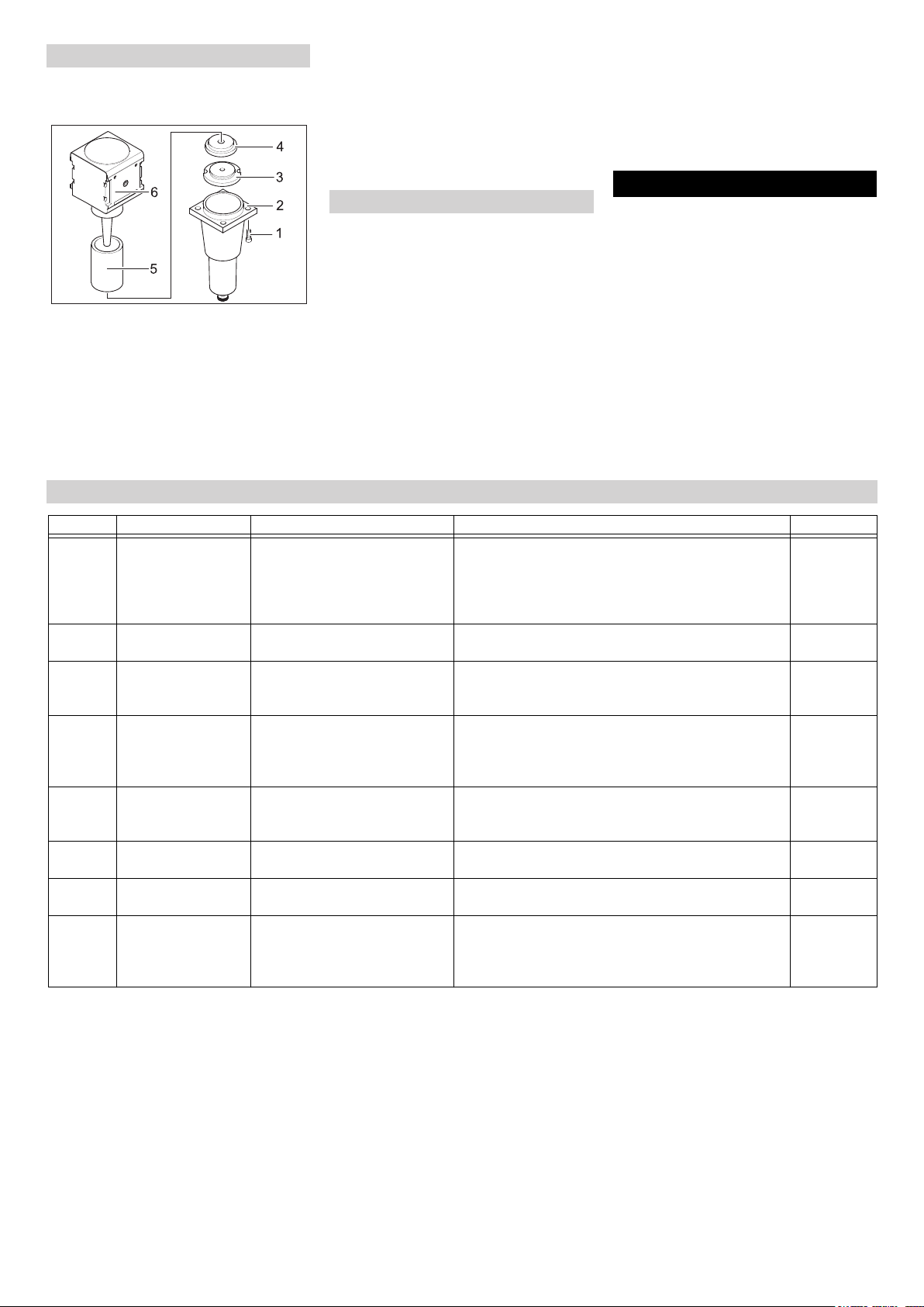
Maintenance Works
Replace the filter insert in the water separator.
1 Screw
2 Lower part
3 Nut
4 Disc
5 Filter inlay
6 Upper section
Loosen 4 screws.
Remove the lower part.
Unscrew the nut.
Remove the disc.
Remove the filter inlay and replace it
with a new filter inlay.
Reassemble the water separator in the
reverse sequence.
Tests
According to the specifications of BDV D
26, the following tests must be conducted
by a technical expert. The results of the
tests must be documented in a test report.
The device operator must carefully store
the test report until the next test.
After a working break of more than one
year
Check the device to see that it is in a
proper condition and is functioning well.
After changing the installation site
Check the device to see that it is in a
proper condition, is functioning well and
has been installed properly.
Faults with display
The operational safety of the device
can get hampered on account of maintenance jobs or any modifications that
have been done.
Check the device to see that it is in a
proper condition, is functioning well and
has been installed properly.
Troubleshooting
Danger!
Risk of accident while working on the appliance. Carry out all the steps described in
the chapter "Shut down" before starting
anhy work on the device.
Danger
Risk of cold burns on account of dry ice or
cold parts of the machine. While working on
the machine, wear appropriate safety gear
for protection against cold or remove dry
ice and let the machine heat up.
Danger
Danger arising from volumetric expansion
and cryogenic burn.
Display Indicator lamp (KL) Possible cause Remedy By whom
E001 KL control voltage
glows red
E002 KL emergency stop
glows red
E003 KL compressed air
glows red
E004 KL dosing glows red Interference in the dosing Turn off the appliance, wait briefly, turn on the appli-
E005 KL jet pistol glows
red
E006 KL jet pistol glows
red
E007 KL compressed air
glows red
E008 KL jet pistol glows
orange
Control voltage too low Turn off the appliance, wait briefly, turn on the appli-
ance once again.
Have the socket checked.
If this error recurs, please contact the Kärcher customer service department
Emergency-stop button has
been pressed.
Pressure of the compressed air
supply too low
Connection between the device
and the jet pistol is faulty.
Short in jet pistol or control cable Replace the jet pistol or the jet hose with a control ca-
Fault in the compressed air regulator valve
The trigger of the jet pistol was
activated during the switch-on
process or the releasing of the
emergency stop key.
Release emergency-stop button by turning. Operator
Increase the pressure.
Turn off the appliance, wait briefly, turn on the appliance once again.
ance once again.
If this error recurs, please contact the Kärcher customer service department
Check for correct connection of the couplings in the
control line.
Check control cable for damages.
ble.
Call Customer Service. Operator
Release the trigger of the jet pistol. Operator
Operator
Operator
Operator
Operator
Operator
- 9
23EN
Page 24

Faults without display on the console
Fault Possible cause Remedy By whom
No display inspite of
power switch in position 1
No compressed air jet
despite the trigger being drawn
Compressed air jet is
too weak
No dry ice pellets in the
compressed air jet
Mains Plug not connected to the socket. Insert the mains plug into a socket. Operator
Fuse F1 blown Remove the side panel and unlock the fuse F1 by
pressing on it.
Compressed air supply has too little pressure Check pressure level. Operator
Jet pressure is set too low Set the jet pressure to a higher level. Operator
Power supply has been interrupted Check power supply. Indicator lamp "Device on"
must glow green.
Emergency-stop button has been pressed. Release emergency-stop button by turning. Indi-
cator lamp "Device on" must glow green.
Control cable not connected properly Check connection between control cable and the
jet pistol and between the control cable and the
device.
Control cable is defective Replace spray agent hose. Operator
Jet pressure is set too low Set the jet pressure to a higher level. Operator
Compressed air supply has too little pressure
or the compressor output is low.
The filter insert in the water separator is
plugged.
Spray agent hose or jet pistol is blocked Let the spray agent hose and jet pistol come to
Dry ice dosing switched off (with jet pistol Advanced only), "Dry ice dosing on/off" button
on the jet pistol illuminates red, display shows
"Ice off".
Dry ice container is empty Refill the dry ice container Operator
Dry ice has melted Empty the dry ice container and refill it with fresh
Vibrator on the dry ice container is not working
Drive motor of the dosing equipment is overloaded
Compressed air is exiting into the dry ice container
Dosing disc in the dosing unit is defective Replace the dosing disc. Customer
Check pressure and output. Operator
Replace the filter inlay in the water separator. Operator
room temperature and remove the blocking. In-
crease working pressure and / or reduce the dry
ice dosing.
Press the dry ice dosing key on the Advanced jet
pistol.
dry ice pellets.
Call Customer Service. Operator
Let the dosing thaw Operator
Clean the pressure balance channel in the dosing
equipment.
Operator
Operator
Operator
Operator
Operator
Operator
Operator
Customer
Service
Service
24 EN
- 10
Page 25

Technical specifications
Electrical connection
Voltage V 220...240
Current type 1~
Frequency Hz 50
Connected load kW 0,6
Protective class IPX4
FI safety switch delta I in A 0,03
Leakage current, typ. mA 7,5
Compressed air
Nominal width of hose Inch 3/4
Pressure supply (max.) MPa (bar) 1,6 (16)
Pressure supply (min.) MPa (bar) 0,2 (2)
Compressed air consumption m
Quality of compressed air dry, oil-free
Performance data
Jet pressure (max.) MPa (bar) 1,6 (16)
Diameter of dry ice pellets (max.) mm 3
Dry ice consumption kg/h 30...120
Dimensions
Contents of dry ice container kg 40
Width mm 716
Depth mm 850
Height mm 1102
Weight with accessories kg 101,5
Weight, operational, with filled dry ice container kg 140
Weight of the jet equipment (spray agent hose, spray gun, tool case) kg 10
Tyre pressure (max.) MPa (bar) 0,2 (2)
Recoil force of hand spray gun (max.) N 100
Torque of jet pistol (max.), only with angled nozzle N 40
Sound pressure level L
Sound pressure level L
pA
WA
Uncertainty K dB(A) 5
Machine vibrations
Jet pistol m/s² 1,2
Hose for spraying agent m/s² 1,2
3
/min 2...12
dB(A) 114
dB(A) 136
- 11
25EN
Page 26

Accessories
Protective clothing
Full view protective goggles, anti-condensation, part no.: 6.321-208.0
Cold protection gloves with anti-slip profile,
category III as per EN 511, part no.: 6.321-
210.0
Ear protection with headgear, part no.:
6.321-207.0
Jet equipment
Round jet nozzle, L, long
Part no.: 4.574-019.0
Round jet nozzle, L, extra long
Part no.: 4.574-016.0
Round jet nozzle, M, long
Part no.: 4.574-018.0
Round jet nozzle, M, short
Part no.: 4.130-418.0
Round jet nozzle, L, short
Part no.: 4.130-419.0
Flat jet nozzle
Part no.: 4.130-423.0
Flat jet nozzle insert, M, 6 mm
Part no.: 4.130-421.0
Flat jet nozzle insert, L, 8 mm
Part no.: 4.130-420.0
Flat jet nozzle insert, XL, 10 mm
Part no.: 4.130-422.0
Angle jet pipe 90°
Part no.: 4.321-203.0
Warranty
The warranty terms published by our competent sales company are applicable in
each country. We will repair potential failures of your appliance within the warranty
period free of charge, provided that such
failure is caused by faulty material or defects in fabrication. In the event of a warranty claim please contact your dealer or the
nearest authorized Customer Service center. Please submit the proof of purchase.
EC Declaration of Conformity
We hereby declare that the machine described below complies with the relevant
basic safety and health requirements of the
EU Directives, both in its basic design and
construction as well as in the version put
into circulation by us. This declaration shall
cease to be valid if the machine is modified
without our prior approval.
Product: Dry ice jet unit
Type: 1.574-xxx
Relevant EU Directives
2006/42/EC (+2009/127/EC)
2004/108/EC
Applied harmonized standards
EN 55014–1: 2006+A1: 2009+A2: 2011
EN 55014–2: 1997+A1: 2001+A2: 2008
EN 60204–1
EN 61000–3–2: 2006+A1: 2009+A2: 2009
EN 61000–3–3: 2008
EN 62233: 2008
Applied national standards
GS-STE-13 (based on it)
The undersigned act on behalf and under
the power of attorney of the company management.
Angle jet pipe 105°
Part no.: 4.321-204.0
Nozzle extension, 300 mm long
Part no.: 4.130-417.0
Handle
Part no.: 6.321-206.0
Scrambler
Part no.: 4.110-015.0
Working light
Part no.: 2.815-422.0
Protective hose for jet pipe, plastic, 100 m
Part no.: 6.667-214.0
CEO
Authorised Documentation Representative
S. Reiser
Alfred Kärcher GmbH Co. KG
Alfred-Kärcher-Str. 28 - 40
71364 Winnenden (Germany)
Phone: +49 7195 14-0
Fax: +49 7195 14-2212
Winnenden, 2013/02/01
Head of Approbation
26 EN
- 12
Page 27
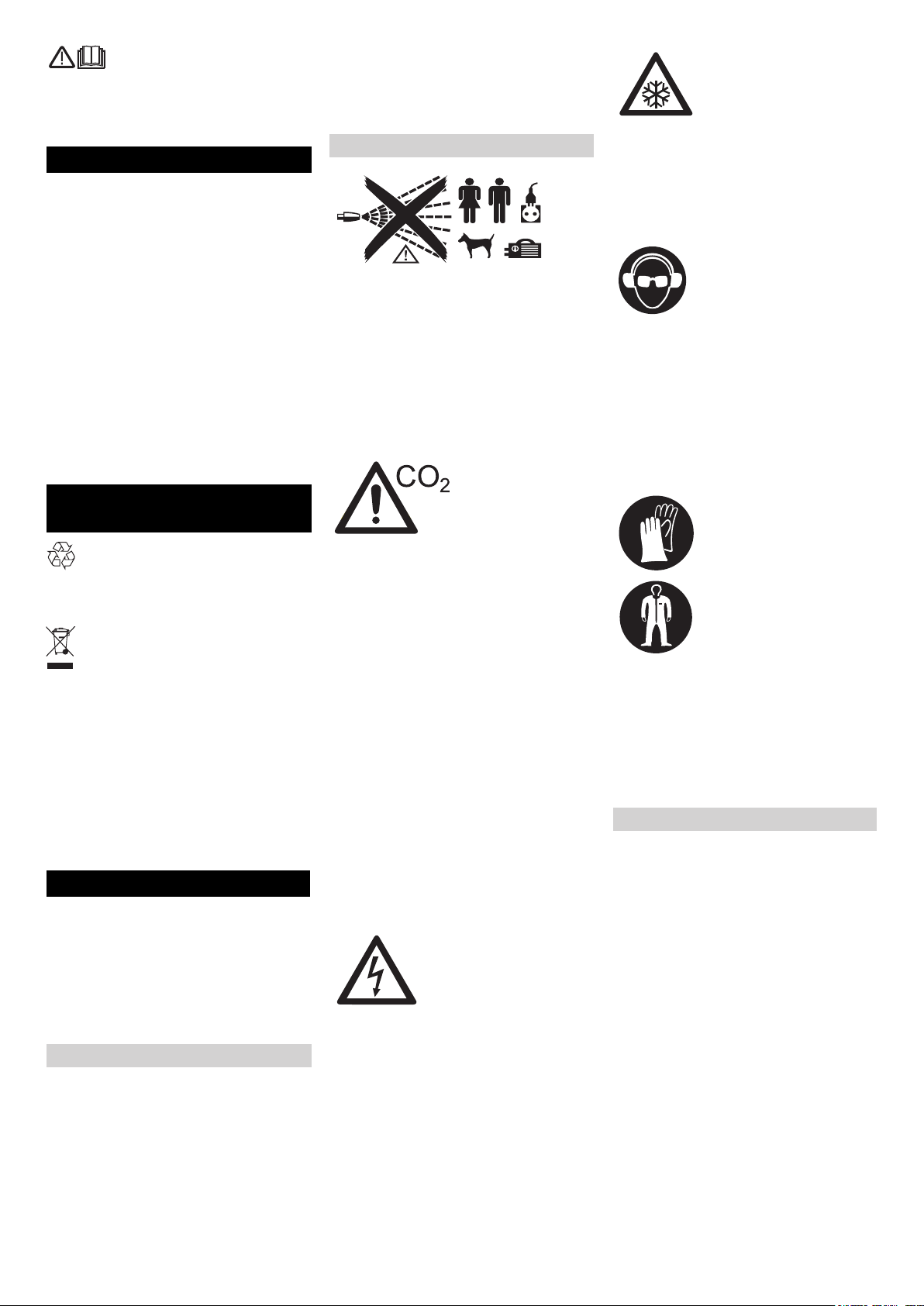
Lire ces notice originale avant la
première utilisation de votre appareil, se comporter selon ce qu'elles requièrent et les conserver pour une
utilisation ultérieure ou pour le propriétaire
futur.
Table des matières
Protection de l’environnement FR . . 1
Consignes de sécurité . . . . FR . . 1
Utilisation conforme . . . . . . FR . . 2
Fonction . . . . . . . . . . . . . . . FR . . 2
Eléments de commande . . . FR . . 3
Mise en service. . . . . . . . . . FR . . 4
Utilisation . . . . . . . . . . . . . . FR . . 6
Mise hors service . . . . . . . . FR . . 8
Transport. . . . . . . . . . . . . . . FR . . 8
Entreposage . . . . . . . . . . . . FR . . 8
Entretien et maintenance . . FR . . 8
Assistance en cas de panne FR . . 9
Caractéristiques techniques FR . 11
Accessoires . . . . . . . . . . . . FR . 12
Garantie . . . . . . . . . . . . . . . FR . 12
Déclaration de conformité CE FR . 12
Protection de
l’environnement
Les matériaux constitutifs de l’emballage sont recyclables. Ne pas jeter
les emballages dans les ordures ménagères, mais les remettre à un système de recyclage.
Les appareils usés contiennent des
matériaux précieux recyclables lesquels doivent être apportés à un système de recyclage. Il est interdit de
jeter les batteries, l'huile et les substances similaires dans l'environnement. Pour cette raison, utiliser des
systèmes de collecte adéquats afin
d'éliminer les appareils hors d'usage.
Instructions relatives aux ingrédients
(REACH)
Les informations actuelles relatives aux ingrédients se trouvent sous :
www.kaercher.com/REACH
Consignes de sécurité
L'appareil peut être utilisé uniquement par
des personnes qui ont lu et compris ce
mode d'emploi. En particulier toutes les
consignes de sécurité doivent être respectées.
Garder ce mode d'emploi ainsi qu'il est
à la disposition de l'opérateur en tout
temps.
Niveaux de danger
Danger
Pour un danger immédiat qui peut avoir
pour conséquence la mort ou des blessures corporelles graves.
몇 Avertissement
Pour une situation potentiellement dangereuse qui peut avoir pour conséquence des
blessures corporelles graves ou la mort.
Attention
Pour une situation potentiellement dangereuse qui peut avoir pour conséquence des
blessures légères ou des dommages matériels.
Des symboles sur l'appareil
Danger
Risque de blessure par des pellets à glace
sèche volants. Ne pas diriger le pistolet de
jet vers des personnes. Eloigner des troisièmes personnes de l'endroit d'utilisation
et pendant le fonctionnement (par exemple
par le blocage).
Ne pas mettre la main dans la buse ou
dans le jet à glace sèche pendant le fonctionnement.
Danger
Danger d'étouffement par le bioxyde de
carbone. Les pellets à glace sèche se composent de dioxyde de carbone solide. Au
fonctionnement de l'appareil le teneur de
dioxyde de carbone de l'air au poste de travail augmente. Aérer suffisamment le poste
de travail, le cas échéant utiliser un détecteur d'alerte personnel. Signes d'une haute
concentration de dioxyde de carbone dans
l'air courant:
– 3 ... 5% : maux de tête, une haute fré-
quence respiratoire.
– 7 ... 10% : maux de tête, envie de vomir,
éventuellement l'inconscience.
Arrêter immédiatement l'appareil lorsque
ces signes aparaîtrent et aller à l'air frais,
avant continuer le travail améliorer des mesures de ventilation ou utiliser un appareil
respiratoire.
Respecter la fiche de données de sécurité
du fabricant de la glace sèche.
Danger
Risque de blessure par les déchargements
électrostatiques, risque de dommage pour
les groupements électroniques. Au processus de nettoyage, l'objet de nettoyage peut
se charger électriquement. Mettre l'objet de
nettoyage à la terre électriquement et
maintenir la mise à la terre pendant tout le
processus de nettoyage.
Danger
Risque d'électrocution. Avant d'ouvrir l'armoire de commande, débrancher le câble
da'limentation de la prise de courant.
Danger
Danger de combustion à réfrigération. La
glace sèche a une température de-79 °C.
Ne jamais toucher sans protection à la
glace sèche et aux parties d'appareil
froides.
Danger
Risque de blessure par des pellets à glace
sèche volants ou des particules de saleté.
Porter des lunettes protectrices bien fermant.
Danger de trouble auditif. Porter une protection d'oreille.
L'équipement de protection ne doit pas empêcher le contact ni la communication avec
l'environnement de travail.
Danger
Risque de blessure par des pellets à glace
sèche volants ou des particules de saleté.
Risque de blessure en touchant des pièces
froides d'appareil.
Porter des gants de protection selon EN
511 et une tenue de protection à manches
longues.
Consignes de sécurité générales
Danger
Risque de blessure par l'appareil que se
met en marche involontairement. Toujours
débrancher le câble d’alimentation de la
prise de courant avant d’effectuer des travaux à l'appareil.
Danger
Risque d'électrocution. Avant d'ouvrir l'armoire de commande, débrancher le câble
da'limentation de la prise de courant.
Danger
Danger des combustions à réfrigération par
la glace sèche ou les parties froides d'appareil. Porter des vêtements de protection
contre le froid appropriés au travail à l'appareil ou éliminer la glace sèche et réchauffer l'appareil.
Danger
Danger par dilatation volumétrique et combustions à réfrigération.
Ne jamais mettre la glace sèche dans la
bouche.
- 1
27FR
Page 28

몇
Avertissement
Danger d'accident par la force de recul du
pistolet de jet. Avant d'actionner le levier de
départ du pistolet de rayon chercher un
emplacement sûr et tenir bien le pistolet de
jet.
Danger
Risque de blessure par des objets volants.
Fixer les objets légers de nettoyage pour
éviter qu'ils sont emportés par le jet à glace
sèche.
몇 Avertissement
Risque d'écrasement par le dispositif de
dosage. Avant d'éliminer la tôle de protection dans le réservoir de glace sèche, débrancher le câble d'alimentation de
l'appareil de la prise de courant.
Dispositions et directives
Les prescriptions et les directives suivantes
sont en vigueur pour exploiter ce portique
en Allemagne (disponibles chez Carl Heymanns Verlag KG, Luxemburger Straße
449, 50939 Köln) :
– BGV D 26 Travaux de rayon
– Instructions de réalisation relatives au
BGV D 26
– BGR 117 Travaux dans des endroits
étroites
– BGR 139 Règles de sécurité relatives
aux personnes - Dispositifs d'alerte.
– BGR 189 Utilisation des vêtements de
protection
– BGR 195 Utilisation des gants de pro-
tection
– BGR 500 Exploitation des moyens de
travail
– BGI 534 Travaux dans des endroits
étroites
– BGI 836 Avertisseur de gaz
Respecter les consignes de sécurité et les
directives de sécurité nationales ainsi que
les directives nationales des associations
préventives des accidents du travail et des
associations spécialisées !
Dispositifs de sécurité
Utilisation conforme
L'appareil sert à l'enlèvement des saletés
avec des pellets ç glace sèche qui sont accélérés par un jet d'air.
L'appareil ne peut être utilisé dans en environnement où il y a un risque d'explosion.
Comme moyen de rayon, utiliser uniquement des pellets à glace sèche. L'utilisation
d'autres moyen de rayon peut endommagée l'appareil.
Fonction
L'air comprimé entre à l'aide d'un détendeur au pistolet de jet. La soupape s'ouvre
en actionnant le levier de départ du pistolet
de jet et le jet d'air sort du pistolet de jet. De
plus, les pellets de glace sèche sont dosés
avec le dispositif de dosage dans le jet
d'air. Le dosage peut être commuté au
moyen de l'interrupteur du mode de fonctionnement. Les pellets à glace sèche
heurtent sur la surface à nettoyer et enlèvent la saleté. Par les pellets à glace
sèche à -79 °C, il y a des tensions de chaleur supplémentaires entre la saleté et l'objet de nettoyage, lesquelles contribuent
également à détacher la saleté. A l'avenir la
glace sèche se transforme immédiatement
en dioxyde de carbone gazeux et nécessite
ainsi un 700ème du volume. La saleté sur
la glace sèche devient de cette façon enfoncé.
Pendant le fonctionnement du jet, un vibrateur au réservoir de la glace sèche s'occupe des postglissements continuels les
pellets à glace sèche.
Touche d'arrêt d’urgence
Lorsque le bouton d'arrêt d'urgence est appuyé, le dosage de glace sèche s'arrête et
le débit d'air de la buse est interrompu.
Désactivation d'urgence
Lâcher le levier de départ du pistolet de
rayon.
Appuyer sur la touche d'arrêt d’ur-
gence.
Le dosage de la glace sèche est arrêté et le
fluxe d'air de la buse est interrompu.
Interrompre l'apport d'air sous pression.
28 FR
- 2
Page 29

Eléments de commande
Appareil
1 Fusible F1, sous le revêtement latéral
2 Raccord air comprimé
3 Vidange de condensat
4 Guidon de poussée
5 Fermeture, coffre
6 Support pour le pistolet de jet
7 Coffre pour accessoires
8 Verrouillage, fixation du coffre
9 Poignée de transport, coffre
10 Attache-câble
11 Soupape de décharge de pression, sé-
parateur d'eau pour vider le condensat
12 Poignée de transport, arceau de pro-
tection
13 Câble secteur avec fiche secteur
14 Sortie de glace sèche pour vider le ré-
servoir
15 Roulettes pivotantes et frein de station-
nement
16 Accouplement du tuyau flexible du
moyen de rayon
17 Pièce de mise à la terre avec borne
18 Accouplement du circuit de commande
19 Pupitre de commande
20 Compartiment de rangement pour ac-
cessoires
21 Couvercle du réservoir de la glace
sèche
Zone de commande Résolution
1 Touche Statistique, réinitialiser les
compteurs
2 Touche Augmenter la pression du jet
3 Touche augmenter le dosage de glace
sèche
4 Interrupteur principal
5 Touche d'arrêt d’urgence
6 Interrupteur à clé
7 Touche diminuer le dosage de glace
sèche
8 Touche Diminuer la pression du jet
9 Ecran
10 Touche Vider le réservoir de glace
sèche
1 Témoin de contrôle de la tension de
commande
vert : Tension de commande en ordre
rouge : Tension de commande trop
faible
jaune : Vidange du réservoir de glace
sèche active
2 Témoin de contrôle Arrêt d’urgence
rouge : Touche d'arrêt d’urgence confirmée
vert : Touche d'arrêt d’urgence non
confirmée
3 Témoin de contrôle de l'air comprimé
vert : Pression en ordre
orange : pression du jet choisie non at-
teinte
rouge : Pression trop faible (inférieure à
0,15MPa/1,5 bar)
- 3
29FR
Page 30
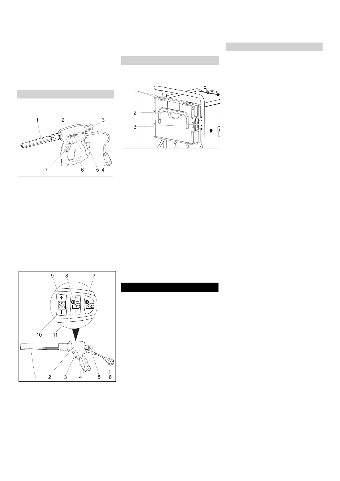
4 Témoin de contrôle du dispositif de do-
sage
vert : Entraînement en ordre
rouge : Panne de l'entraînement
5 Témoin de contrôle du pistolet de jet
vert : pistolet de jet en ordre
orange : levier de départ du pistolet de
jet actionné lors de la mise en marche
rouge : pistolet de jet débranché ou cir-
cuit de commande endommagé
6 Champ d'affichage
Dispositif de jet
Pistolet de sablage
1 Buse
2 Pistolet de jet
3 Accouplement du tuyau flexible du
moyen de rayon
4 Accouplement du circuit de commande
5 Manette de sécurité
6 Levier de départ
7 Interrupteur du mode de fonctionne-
ment
Position "1" : Jet d'air comprimé
Position "2" : Jet de glace sèche (air
comprimé et pellets à glace sèche)
Pistolet de sablage Advanced (option)
8 Touche augmenter le dosage de glace
sèche
9 Touche Augmenter la pression du jet
10 Touche Diminuer la pression du jet
11 Touche diminuer le dosage de glace
sèche
Coffre pour accessoires
Le coffre sert au rangement des buses et
aux outils qui en font partie.
1 Fermeture
2 Poignée de transport
3 Déverrouillage
Ouvrir le coffre
Ouvrir les orifices.
Basculer le couvercle vers le bas.
Attention
Risque d'endommagement ; ne poser aucun objet lourd sur le couvercle ouvert.
Séparer le coffre de l'appareil.
Appuyer sur le verrouillage et retirer le
coffre.
Mettre le coffre au niveau de l'appareil.
Tourner le coffre avec les fermetures
vers le haut.
Positionner un côté du coffre au niveau
de la fixation et l'enclencher.
Appuyer le coffre contre l'appareil et en-
clencher la fixation qui fait face.
Connecter le circuit de commande avec
l'appareil.
Connecter le circuit de commande avec
le pistolet de jet.
Buses
Remarque
La sélection des buses dépend de la matière première de l'objet de nettoyage et de
la saleté.
De même, le volume d'air à disposition a
une influence déterminante sur la sélection
des buses.
Toutes les buses sont vissées sans outil
sur le filetage du pistolet de jet. Les pans à
la buse servent pour desserrer les buses
bien fixes avec un clé à fourche.
Attention
Risque de collage dû au froid. Graisser,
avant le montage, les filetages de buse
avec la graisse ci-jointe.
Sélection de l'injecteur
Le tableau suivant montre la consommation d'air avec des buses différentes.
Chaque buse est caractérisée par un indice
de débit d'air XS - XXL.
Avec le tableau des buses, la consommation d'air peut être ainsi calculée pour
chaque buse.
1 Buse
2 Pistolet de jet
3 Levier de départ
4 Bouton du fusible
5 Accouplement du tuyau flexible du
moyen de rayon
6 Accouplement du circuit de commande
7 Touche Dosage de la glace sèche
Marche/Arrêt
S'allume en rouge lorsque le dosage de
la glace sèche est arrêté
Mise en service
Danger
Risque de blessure causée par des pellets
de glace sèche.
A la préparation de l'appareil, contrôler le
bon état de tous les composants, particulièrement le flexible de jet. Remplacer les
composants endommagés par des nouveaux.
Nettoyer les composants sales et contrôler
la fonction.
Poser l'appareil sur des surfaces hori-
zontales et planes et bloquer les frein
d'immobilisation à la monture de roulette.
Remarque :
Pour protéger de l'usure et de l'encrassement, le flexible d'agent de pulvérisation
peut être enfilé avec un flexible de protection. En cas de besoin, pousser le flexible
de protection avant de le connecter par le
flexible de lance.
Raccorder et s'assurer le flexible de
moyen de jet avec l'appareil.
Raccorder et s'assurer le pistolet de jet
avec le flexible de moyen de jet.
30 FR
- 4
Page 31

Agressivité du sa-
très faible faible moyen élevé très élevé
blage
Pression (bar) 2 3 4 5 6 7 8 9 10 11 12 13 14 15 16
Taille d'injecteur
Puissance surfacique
XS Ø5 mm 0,40 0,70 0,90
S Ø6 mm 0,70
M Ø7 mm 0,93
L Ø8 mm
XL Ø9 mm
XXL Ø10 mm
1,05 1,45 1,80 2,07 2,40 2,78 3,14 3,48 3,78 4,13 4,35 4,70 5,10 5,40
1,38 1,85 2,28 2,64 3,05 3,63 4,03 4,57 4,80 5,30 5,80 6,22 6,65 7,15
1,09 1,64 2,26 2,78 3,20 3,79 4,40 4,95 5,45 5,90 6,40 7,15 7,67 8,15 8,80
1,50 2,16 2,88 3,50 4,03 4,60 5,41 6,01 6,53 7,27 8,08 8,70 9,28 9,80 10,40
1,52 2,20 2,97 3,66 4,27 5,00 5,82 6,52 7,40 8,00 8,90 9,50 10,05 10,70 11,30
Consommation d'air en m
1,10 1,30 1,60 1,80 2,00 2,30 -- -- -- -- -- --
3
/min
m3/min
...1 Réseau d'air comprimé
industriel
Amorceur du compresseur
par ex. Käser M 17,
Compair C 14
1...2 Réseau d'air comprimé
industriel
petit compresseur
par ex. Käser M 31,
Compair C 20GS
2...3 compresseur moyen
3...5
par ex. Käser M 57,
Compair C 35
5...7 compresseur moyen
par ex. Käser M 80,
Compair C 55
7...10 grand compresseur
par ex. Käser M 122,
Compair C 105
10... très grand compresseur
par ex. Käser M 250,
Compair C 200
Buse à jet rond
A côté de la buse à jet rond livrée, il y a
d'autres buses à jet rond avec différentes
coupes transversales comme accessoire.
Buse à jet plat
1 Diffuseur
2 Écrou chapeau
3 Embout
La buse à jet plat se compose d'un embout
et d'un diffuseur. Comm accessoire il y a
des embout avec des différentes coupes
transversales.
Poser l'embout sur l'embout filète du
pistolet de jet et serrer manuellement.
Poser le diffuseur sur l'élément de
buse.
Tourner le diffuseur ainsi que le jet plat
prend l'alignement souhaité au pistolet
de jet.
Serrer manuellement l'écrou raccord.
Scrambler (accessoire)
Le scrambler coupe les pellets à glace
sèche en petits morceaux et est monté
entre le pistolet de jet et la buse.
L'ajustage des 4 plaques perforées dans le
scrambler indique le degré de fragmentation.
Sélectionner le degré de fragmentation:
1 Fermeture
2 magasin
3 Plaque perforée
Dévisser le boulonnage.
Sortir le magsin avec les plaques perfo-
rées.
1 Buse à jet rond, courte
2 Buse à jet rond, longue
3 Buse à jet rond, extra longue
Poser la buse à jet rond sur l'embout fi-
lète du pistolet de jet et serrer manuellement.
- 5
Placer les plaques perforées dans le
magasin comme indiqué ci-dessus (3
possibilités). Les dimensions de l'illustration se rapportent à la taille des ouvertures.
Placer le magasin avec les plaques per-
forées dans le scrambler.
Visser le boulonnage et serrer à fond.
31FR
Page 32

Prolongation de buse (accessoire)
Une prolongation peut être mise entre le
pistolet de jet et la buse.
Lance coudée (accessoire)
Une lance coudée est placée entre le pistolet à jet et la buse.
1 Lance coudée 105°
2 Lance coudée 90°
몇 Avertissement
Risque de blessure. Lors de l'utilisation de
la lance coudée, un moment de rotation sur
le pistolet de sablage agit en plus sur la
force de réaction. Bien retenir la poignéepistolet.
Commencer le travail avec une faible pression de jet et augmenter la pression du jet
en cas de besoin.
Poignée (accessoire)
La poignée peut être fixée à la rallonge.
Eclairage de travail (accessoires)
(uniquement par pistolet de sablage Advanced)
L'éclairage de travail est placé entre le pistolet à jet et la buse. La mise en marche/arrêt est décrite au chapitre "Utilisation/
Réglages de base".
Raccorder l'air comprimé.
Remarque
Pour un fonctionnement sans défaut, l'air
comprimé doit avoir une basse teneur en
humidité. L'air comprimé doit être libre de
l'huile, de saleté et des corps étrangers.
Le compresseur doit être équipé au moins
d'un refroidisseur secondaire, d'un séparateur d'eau et d'huile.
Fermer la soupape de décharge de
pression.
Connecter l'alimentation d'air comprimé
au raccord d'air comprimé de l'appareil.
La pression d'alimentation maximale
autorisée de 1,6MPa (16 bar) ne doit
pas être dépassée.
Établir le raccordement de réseau
Danger
Risque d'électrocution.
La prise de courant doit être installée par
un électricien et doit correspondre à la CEI
60364-1.
L'appareil doit être protégé par un disjoncteur du type B, 30 mA.
Vérifier le bon état de la conduite de raccordement de réseau de l'appareil avant
chaque fonctionnement. Ne pas mettre
l'appareil en service avec un câble endommagé. Laisser changer le câble endommagé par un électricien.
Le câble de prolongation doit assurer une
protection IPX4 et le câble doit correspondre au moins à H 07 RN-F 3G1,5.
Brancher la fiche secteur dans une
prise de courant.
Utilisation
Remplir glace sèche
Danger
Danger de combustion à réfrigération. La
glace sèche a une température de -79 °C.
Ne jamais toucher sans protection à la
glace sèche et aux parties d'appareil
froides. Porter des gants de protection et
des vêtements de protection.
Ouvrir le couvercle du réservoir de la
glace sèche.
Contrôler la présence de corps étran-
gers et de condensat dans le réservoir
de glace sèche, les éliminer.
Remplir des pellets à glace sèche dans
le réservoir.
Attention
Risque d'endommagement de l'appareil.
N'utiliser que des pellets à glace sèche en
tant que moyen de pulvérisation. L'utilisation d'autres moyens entraîne la perte de la
garantie.
Fermer le couvercle du réservoir de la
glace sèche.
Remarque
Pour éviter des pannes par des pellets à
glace sèche fondus, il est sensé de
consommer rationnellement le contenu du
réservoir de la glace sèche avant qu'une
nouvelle glace sèche soit versée. Avant
une interruption de travail prolongée, faire
fonctionner l'appareil jusqu'à ce que le réservoir de glace sèche soit vide ou vider le
réservoir avec la fonction Vider la glace
sèche.
Réglages
Remarque
Les réglages dépendent de la matièrie première de l'objet de nettoyage et de la saleté.
Tourner la touche d'arrêt d'urgence
pour la déverrouiller.
Régler l'interrupteur principal sur "I".
Tourner l'interrupteur à clé dans le sens
horaire.
Régler la pression du jet avec les
touches augmenter/diminuer la pression du jet.
Remarque
Plus haut la pression du jet est réglée, d'autant plus haut (plus agressivement) est l'effet de nettoyage.
Régler le dosage de la glace sèche
avec les touches augmenter/diminuer
le dosage de la glace sèche.
Tourner l'interrupteur à clé dans le sens
inverse des aiguilles d'une montre et tirer la clé.
La fermeture automatique du trou de la
clé permet d'éviter la salissure au cours
du fonctionnement.
Lorsque la clé est retirée, l'appareil est
à l'abris d'un déréglage des paramètres
et la réinitialisation des valeurs statistiques.
Fonctionnement
Effectuer des travaux de maintenance
"quotidiennement avant le début du
fonctionnement" (cf. le chapitre "Maintenance et entretien").
Danger
Risque de blessure par des pellets à glace
sèche volants. Ne pas diriger le pistolet de
jet vers des personnes. Eloigner des troisièmes personnes de l'endroit d'utilisation
et pendant le fonctionnement (par exemple
par le blocage).
Ne pas mettre la main dans l'ouverture de
la buse ou dans le rayon à glace sèche
pendant le fonctionnement.
Avant de séparer la liaison entre le pistolet
du jet et le tuyau flexible de moyen de jet et
entre le tuyau flexible de moyen de jet et
appareil fermer absolument l'apport d'air
sous pression, rendre l'appareil sans pression et débrancher le câble d'alimentation
de la prise de courant.
Barrer la zone de travail pour éviter l'ac-
cès des personnes pendant le fonctionnement.
32 FR
- 6
Page 33

Danger
Danger d'étouffement par le bioxyde de
carbone. Les pellets à glace sèche se composent de dioxyde de carbone solide. Au
fonctionnement de l'appareil le teneur de
dioxyde de carbone de l'air au poste de travail augmente. Aérer suffisamment le lieu
de travail ; le cas échéant, utiliser un détecteur d'alerte personnel ou une protection
respiratoire.
Signes d'une haute concentration de
dioxyde de carbone dans l'air courant :
– 3 ... 5% : maux de tête, une haute fré-
quence respiratoire.
– 7 ... 10% : maux de tête, envie de vomir,
éventuellement l'inconscience.
Arrêter immédiatement l'appareil lorsque
ces signes aparaîtrent et aller à l'air frais,
avant continuer le travail améliorer des mesures de ventilation ou utiliser un appareil
respiratoire.
Le dioxyde de carbone se concentre dans
des endroits situés en profondeur. Éviter
l'accumulation par des mesures d'aération
actives.
Respecter la fiche de données de sécurité
du fabricant de la glace sèche.
Danger
Danger dû à la présence de substances
toxiques Si des poussières nocives sont
créées lors du traitement, il est impératif de
prendre des mesures de sécurité correspondantes avant de commencer les travaux.
Danger
Risque d'explosion !
Ne pas traiter simultanément des métaux
légers et des pièces contenant du fer.
Si des métaux légers et des pièces contenant du fer sont traités en alternance, l'espace de travail ainsi que le dispositif
d'aspiration doivent être nettoyés avant le
traitement de l'autre matériau respectif.
Danger dû à une explosion de poussières.
Si des poussières inflammables se produisent lors des travaux, des accumulations de poussières doivent être évitées.
Dépoussiérez régulièrement avant que des
quantités critiques soient accumulées.
Lors du travail dans les espaces étroits
s'assurer qu'il y a une bonne ventilation
pour pouvoir tenir la concentration de
dioxyde de carbone dans l'air d'espace
au-dessous de la valeur dangereuse.
Le cas échéant, fixer l'objet de net-
toyage.
Danger
Risque de blessure par les déchargements
électrostatiques, risque de dommage pour
les groupements électroniques. Au processus de nettoyage, l'objet de nettoyage peut
se charger électriquement. Mettre l'objet de
nettoyage à la terre électriquement et
maintenir la mise à la terre pendant tout le
processus de nettoyage.
몇 Avertissement
Risque de blessure par suite de trébuchement
Poser le flexible d'agent de pulvérisation et
le câble électrique de telle sorte qu'il
n'existe aucun risque de trébuchement
pendant le travail.
Attention
Risque d'endommagement par des corps
étrangers tombant dans le conteneur de
glace sèche. Maintenir le couvercle du
conteneur de glace sèche fermé pendant le
fonctionnement.
Connecter électroniquement la pièce
de mise à la terre à l'objet de nettoyage
ou mettre l'objet de nettoyage à la terre
d'une autre façon.
Porter des vêtements de protection,
des gants de protection, de lunettes
protectrices et une protection d'oreille.
Activer l'apport d'air souspression.
Tourner la touche d'arrêt d'urgence
pour la déverrouiller.
Régler le mode de fonctionnement du
jet d'air comprimé sur "1" ou le jet de la
glace sèche sur "2" à l'interrupteur du
mode de fonctionnement du pistolet de
jet.
Choisir un emplacement sûr et prendre
une tenue sûre pour ne pas perdre
l'équilibre de la force de recul du pistolet
de jet.
Afin d'empêcher la mise en place soudaine de la réaction à la lance, une augmentation lente de la pression du jet
peut être réglée (voir "Utilisation/Réglages de base", option démarrage
lent).
Enfoncer le bouton de sécurité du pisto-
let à jet.
Activer le jet de la glace sèche en ac-
tionnant le levier de départ du pistolet
de jet et effectuer le processus de nettoyage.
Remarque
Pour l'utilisation du pistolet de sablage Advanced, l'addition de pellets de glace sèche
peut être activée et désactivée avec la
touche Marche/Arrêt du dosage de la glace
sèche sur le pistolet de sablage. Lorsque le
dosage est désactivé, la touche est rouge
et "Ice off" s'affiche à l'écran.
De plus, pour l'utilisation du pistolet de sablage Advanced, la pression du jet et la
quantité de glace sèche peuvent être réglées sur le pistolet de sablage.
Attention
Risque d'endommagement du dispositif dû
à la saleté. Maintenir le couvercle du réservoir de glace sèche fermé pendant le fonctionnement du jet, afin d'éviter l'infiltration
de saletés projetées par le jet.
Désactivation d'urgence
Lâcher le levier de départ du pistolet de
rayon.
Appuyer sur la touche d'arrêt d’ur-
gence.
Le dosage de la glace sèche est arrêté et le
fluxe d'air de la buse est interrompu.
Interrompre l'apport d'air sous pression.
Mise en service après arrêt
d'urgence
Tourner la touche d'arrêt d'urgence
pour la déverrouiller.
Interrompre le fonctionnement
Lâcher le levier de départ du pistolet de
rayon.
En cas d'arrêt de fonctionnement, le
pistolet de jet peut être mis sur le support à l'appareil.
Remarque
À l'interruption de fonctionnement plus
longue, les pellets à glace sèche peuvent
s'agglutiner dans le réservoir de la glace
sèche. Ne pas interrompre le fonctionnement plus que 20 minutes. Vider le réservoir de glace sèche en cas d'interruptions
prolongées.
Vidanger le condensat
Un séparateur d'eau nettoie l'air comprimé
envoyé dans l'appareil. Ainsi, le condensat
s'accumule dans le séparateur d'eau, qui
doit être vidé de temps en temps.
Poser la cuvette de récupération sous
la vidange de condensat.
Ouvrir lentement la soupape de dé-
charge de pression et attendre que le
condensat se soit échappé de l'appareil.
Remarque
Veuillez éliminer le condensat de manière
favorable à l'environnement.
Fonction statistique
Ouvrir les valeurs
Régler l'interrupteur principal sur "I".
Enfoncer brièvement la touche Statis-
tique, la durée de fonctionnement s'affiche.
t : temps de fonctionnement depuis la
dernière réinitialisation.
T : temps total de fonctionnement.
Enfoncer brièvement la touche Statis-
tique, la quantité de glace sèche traitée
s'affiche.
m : quantité de glace sèche depuis la
dernière réinitialisation.
M : quantité totale de glace sèche.
Enfoncer brièvement la touche Statis-
tique, la quantité moyenne de glace
sèche utilisée s'affiche.
q : quantité moyenne de glace sèche
utilisée depuis la dernière réinitialisation.
Q : quantité moyenne totale de glace
sèche utilisée.
- 7
33FR
Page 34

Réinitialiser les valeurs
Tourner l'interrupteur à clé dans le sens
horaire.
Enfoncer la touche Statistique 4 se-
condes.
Remarque
Les valeurs totales ne peuvent pas être remises à zéro.
Réglages de base
Enfoncer simultanéement les touches
augmenter la pression du jet et diminuer la pression du jet et les maintenir,
tourner simultanément l'interrupteur à
clé dans le sens des aiguilles d'une
montre.
En mode Réglages de base, les touches
ont les fonctions suivantes :
1 Augmenter la valeur
2 Diminuer la valeur
3 Point de menu vers le haut
4 Point de menu vers le bas
Plage de
réglage
Point de menu
0, 1, 2, 3,
4, 5 secondes
Démarrage lent
1, 2, 3, 4, 5
minutes
T_Dump
métrique,
impérial
Langue
ON/OFF Activer/désactiver l'éclai-
Eclairage
ON/OFF Fonctionnement de dé-
Mode démo
Annuler les réglages de base
Tourner l'interrupteur à clé dans le sens
antihoraire.
Description
Démarrage lent, durée
jusqu'à l'obtention de la
pression du jet sélectionnée
Durée du processus de
vidange de la glace
sèche
Unités de mesure
métrique : kg/h, MPa
impérial : lbs, psi
rage de la buse (en option)
monstration : le service
est simulé, la distribution
d'air comprimé et de
glace sèche est bloquée.
Mise hors service
Danger
Danger de combustion à réfrigération. La
glace sèche a une température de -79 °C.
Ne jamais toucher sans protection à la
glace sèche et aux parties d'appareil
froides. Porter des gants de protection et
des vêtements de protection.
Danger
Risque de blessure par des pellets à glace
sèche volants. Ne pas diriger le pistolet de
jet vers des personnes. Eloigner des troisièmes personnes de l'endroit d'utilisation
et pendant le fonctionnement (par exemple
par le blocage).
Fermer l'alimentation d'air comprimé.
Poser la cuvette de récupération sous
la vidange de condensat.
Ouvrir lentement la soupape de dé-
charge de pression et attendre que le
condensat et l'air comprimé se soient
échappés de l'appareil.
Placer le réservoir de récupération sous
la sortie de glace sèche.
Enfoncer la touche Vidange du réser-
voir de glace sèche et attendre jusqu'à
ce que ce réservoir soit vide.
La vidange de la glace sèche s'arrête
après le temps programmé (voir "Réglages de base").
Au besoin, enfoncer plusieurs fois la
touche Vidange du réservoir de glace
sèche.
Remarque
Veuillez éliminer le condensat de manière
favorable à l'environnement.
Positionner l'interrupteur sur '0/OFF'.
Séparer l'appareil de l'alimentation d'air
comprimé.
Débrancher la fiche secteur.
Nettoyer et enrouler la pièce de mise à
la terre.
Éliminer les déchets selon les directives
locales.
Transport
Danger
Risque d'accident par des restes de glace
sèche dans l'appareil. Avant le transport
dans les véhicules fermés, la glace sèche
doit être éloignée complètement de l'appareil pour éviter des risques des personnes
accompagnant par dioxyde de carbone.
Effectuer, avant le transport, tous les
pas décrites dans le chapitre "Mise hors
de service".
Poser l'appareil sur le véhicule de
transport.
Bloquer les freins de la monture de rou-
lette.
Fixer l'appareil avec des sangles sur le
véhicule.
Entreposage
Attention
Risque de blessure et d'endommagement !
Prendre en compte le poids de l'appareil à
l'entreposage.
Cet appareil doit uniquement être entreposé en intérieur.
Entretien et maintenance
Consignes pour la maintenance
La maintenance régulière selon le plan de
maintenance suivant est primordial pour
assurer un fonctionnement fiable de la station de lavage.
Utiliser uniquement des pièces de rechange d'origine du fabricant ou bien des
pièces recommandées telles que
– pièces de rechange et d'usure,
– accessoires,
– matériel,
– aux détergents.
Danger !
Risque d'accident au travail à l'appareil. Effectuer, avant commencer de travailler à
l'appareil, tous les pas de travail du chapitre "Mise hors de service".
Danger
Danger des combustions à réfrigération par
la glace sèche ou les parties froides d'appareil. Porter des vêtements de protection
contre le froid appropriés au travail à l'appareil ou éliminer la glace sèche et réchauffer l'appareil.
Danger
Danger par dilatation volumétrique et combustions à réfrigération.
Ne jamais mettre la glace sèche dans la
bouche.
Attention
Risque d'endommagement. Ne pas nettoyer le pistolet de pulvérisation avec du diluant, de l'essence ou du détergent
contenant de l'huile.
Contrat de maintenance
Nous vous recommandons de conclure un
contrat de maintenance afin de pouvoir assurer un fonctionnement fiable de la station
de lavage. Veuillez vous adresser à votre
service après-vente Kärcher responsable.
Plan de maintenance
Quotidiennement avant début de fonctionnement
Examiner le tuyau flexible de moyen de
rayon avec soin sur des déchirures, des
lieux de brisure et d'autres dommages.
Les lieux mous dans le tuyau flexible
montrent l'usure sur l'intérieur du tuyau
flexible. Remplacer le tuyau flexible défectueux ou usé par un nouveau.
Examiner les câbles électriques et les
prises sur des dommages. Laisser
échanger les pièces défectueuses du
service après-vente.
34 FR
- 8
Page 35

Toutes les 100 heures de service
Vérifier si les accouplements au tuyau
flexible de moyen de jet, à l'appareil et
au pistolet de jet sont endommagés et
usés. Remplacer le tuyau défectueux,
laisser remplacer les accouplement défectueux à l'appareil ou au pistolet de jet
par le service après-vente.
Vérifier si le dispositif de dosage est en-
dommagé et étanche. S'il y a des dommages/non étanchéités, informer le
service après-vente.
Contrôler le bon serrage des capu-
chons de fixation des roues arrière.
Tous les 500 heures ou annuellement
Laisser contrôler l'appareil par le ser-
vice après-vente.
Tous les 2 ans
Renouveler le tuyau flexible de moyen
de jet au moins tous les 2 ans.
Ouvrir l'appareil
Pour la réalisation de certains travaux de
maintenance, les revêtements latéraux de
l'appareil doivent être éliminés:
Dévisser l'écrou.
Retirer le disque.
Retirer l'élément de filtre et changer par
un nouveau.
Monter le séparateur de nouveau en
ordre inverse.
Essais
Selon BGV D 26 les examens suivants
doivent être entrepris à l'appareil par un
compétent. Les résultats de l'essai doivent
être retenus dans un certificat d'essai. Le
certificat d'essai doit être gardé par l'exploitant de l'appareil jusqu'à l'essai prochain.
Après l'interruption de service de plus
qu'un an
Vérifier l'appareil sur la qualité et fonc-
tion réglementaire.
Après modification du lieux d'installation
Vérifier l'appareil sur la qualité, la fonc-
tion et l'installation réglementaire.
Après des travaux de réparation ou
après des changements ceux-ci
peuvent influencer la sécurité de fonctionnement
Vérifier l'appareil sur la qualité, la fonc-
tion et l'installation réglementaire.
Assistance en cas de panne
Danger !
Risque d'accident au travail à l'appareil. Effectuer, avant commencer de travailler à
l'appareil, tous les pas de travail du chapitre "Mise hors de service".
Danger
Danger des combustions à réfrigération par
la glace sèche ou les parties froides d'appareil. Porter des vêtements de protection
contre le froid appropriés au travail à l'appareil ou éliminer la glace sèche et réchauffer l'appareil.
Danger
Danger par dilatation volumétrique et combustions à réfrigération.
Ne jamais mettre la glace sèche dans la
bouche.
1 Attache rapide
2 Revêtement latéral
Ouvrir les attaches rapides dans le
sens inverse des aiguilles d'une
montre.
Déposer l'habillage latéral.
Travaux de maintenance
Remplacer l'élément de filtre dans le séparateur d'eau
1 Vis
2 Parte inférieure
3 Ecrou
4 Disque
5 Elément d'un filtre
6 Parte supérieure
Dévisser 4 vis.
Retirer la parte inférieure.
- 9
35FR
Page 36

Défauts qui s'affichent à l'écran
Affichage
de l'écran
E001 Le TC de la tension de
E002 Le TC d'arrêt d'urgence
E003 Le TC de l'air comprimé
E004 Le TC du dosage est
E005 Le TC du pistolet de jet
E006 Le TC du pistolet de jet
E007 Le TC de l'air comprimé
E008 Le TC du pistolet de jet
Témoin de contrôle
(TC)
commande est rouge
est rouge
est rouge
rouge
est rouge
est rouge
est rouge
est orange
Eventuelle cause Remède Par qui
Tension de commande trop faible Mettre l'appareil hors service, attendre un moment puis le ral-
lumer.
Faire contrôler la prise.
Si le code d'erreur se reproduit, informer le service client Kärcher
La touche d'arrêt d’urgence est enfoncée
Pression de l'alimentation en air
comprimé trop faible
Erreur dans l'unité de dosage Mettre l'appareil hors service, attendre un moment puis le ral-
Panne de connexion entre l'appareil
et le pistolet de jet.
Court-circuit dans le pistolet de jet
ou le câble de commande
Panne de la soupape de règle d'air
comprimé
Pendant la mise en marche ou le
déverrouillage de la touche d'arrêt
d'urgence, le levier de départ du pistolet de jet a été actionné.
Tourner la touche d'arrêt d'urgence pour la déverrouiller. Opérateur
Augmenter la pression.
Mettre l'appareil hors service, attendre un moment puis le rallumer.
lumer.
Si le code d'erreur se reproduit, informer le service client Kärcher
Contrôler la connexion correcte des accouplements du circuit
de commande.
Examiner les câbles de commande, s'ils sont endommagés.
Remplacer le pistolet de jet ou le tuyau de jet par le câble de
commande.
Adresser au Centre de Service Après-vente. Opérateur
Lâcher le levier de départ du pistolet de rayon. Opérateur
Opérateur
Opérateur
Opérateur
Opérateur
Opérateur
Défauts qui ne s'affichent pas à l'écran
Panne Eventuelle cause Remède Par qui
Pas d'affichage sur
l'écran bien que le sectionneur général soit enclenché
Aucun jet d'air comprimé
malgré le levier de départ
tiré
Le jet d'air comprimé est
trop faible
Aucunes pellets à glace
sèche dans le jet d'air
comrpimé.
Fiche électrique pas branchée dans la prise électrique.
Fusible F1 déclenché Retirer le revêtement latéral et déverrouiller le fusible F1
L'approvisionnement d'air comprimé a trop peu de
pression
La pression du jet est réglée trop faible Remonter la pression du jet. Opérateur
L'alimentation de tension est interrompue. Contrôler l'alimentation de tension. Le voyant de
La touche d'arrêt d’urgence est enfoncée Tourner la touche d'arrêt d'urgence pour la déverrouiller.
Le circuit de commande n'est pas brancher correctement.
Le circuit de commande est défectueux Remplacer le tuyau flexible de moyen de jet. Opérateur
La pression du jet est réglée trop faible Remonter la pression du jet. Opérateur
L'approvisionnement d'air comprimé a trop peu de
pression ou le débit du compresseur est très faible.
Elément de filtre dans le séparateur d'eau bouché. Remplacer l'élément de filtre dans le séparateur d'eau. Opérateur
Le tuyau flexible de moyen de jet ou le pistolet de
jet est bouché
Dosage de glace sèche désactivé (uniquement
pour le pistolet de sablage Advanced), la touche
dosage de la glace sèche marche/arrêt sur le pistolet de jet est rouge, affichage « Ice off ».
Le réservoir de la glace sèche est vide Remplir le réservoir de la glace sèche Opérateur
La glace sèche est fondée Vider le réservoir de la glace sèche et le remplir avec de
Le vibrateur au réservoir de la glace sèche ne fonctionne pas
Le moteur d'entraînement du dispositif de dosage
est surchargé
Sortie d'air comprimé dans le réservoir de la glace
sèche
Le disque de dosage dans l'unité de dosage est défectueux
Brancher la fiche secteur dans une prise de courant. Opérateur
Opérateur
en appuyant dessus.
Contrôler la pression. Opérateur
Opérateur
contrôle "Appareil marche" doit être vert.
Opérateur
Le voyant de contrôle "Appareil marche" doit être vert.
Contrôler la connexion entre le circuit de commande et
le pistolet de jet ainsi qu'entre le circuit de commande et
l'appareil.
Contrôler la pression et le débit. Opérateur
Laisser dégeler le tuyau flexible de moyen de jet et le
pistolet de jet et éliminer le bouchage. Augmenter la
pression de travail et / ou réduire le dosage de glace
sèche.
Enfoncer la tache Dosage de la glace sèche sur le pistolet de sablage Advanced.
nouveaux pellets à glace sèche .
Adresser au Centre de Service Après-vente. Opérateur
Laisser dégeler le dispositif de dosage Opérateur
Nettoyer le canal d'équilibrage des pressions dans le
dispositif de dosage.
Remplacer le disque de dosage. Service après-
Opérateur
Opérateur
Opérateur
Opérateur
Service aprèsvente
vente
36 FR
- 10
Page 37

Caractéristiques techniques
Branchement électrique
Tension V 220...240
Type de courant 1~
Fréquence Hz 50
Puissance de raccordement kW 0,6
Classe de protection IPX4
Disjoncteur de protection FI delta I in A 0,03
Courant de fuite, type mA 7,5
Air comprimé
Largeur nominale du tuyau flexible Pouces 3/4
Pression d'alimentation (max.) MPa (bars) 1,6 (16)
Pression d'alimentation (min.) MPa (bars) 0,2 (2)
Consommation d'air comprimé m
Qualité d'air comprimé sec, sans huile
Performances
Pression du jet (max.) MPa (bars) 1,6 (16)
Diamètre des pellets à glace sèche (max.) mm 3
Consommation de la glace sèche kg/h 30...120
Dimensions
Contenu du réservoir de la glace sèche kg 40
Largeur mm 716
Profondeur mm 850
Hauteur mm 1102
Poids avec accessoires kg 101,5
Poids, prêt à fonctionner, avec le réservoir de glace sèche rempli kg 140
Pression de gonflage des pneumatiques (max.) MPa (bar) 0,2 (2)
Poids dispositif de jet (flexible central de jet, pistolet de jet, poche de l'appareil) kg 10
Force de réaction max. du pistolet de jet (max.) N 100
Couple du pistolet de jet (max.), uniquement pour les buses coudées N 40
Niveau de pression sonore L
Niveau de puissance sonore L
pA
WA
Incertitude K dB(A) 5
Vibrations de l'appareil
Pistolet de jet m/s² 1,2
Tuyau flexible de moyen de jet m/s² 1,2
3
/min 2...12
dB(A) 114
dB(A) 136
- 11
37FR
Page 38

Accessoires
Vêtements de protection
Lunettes de protection complètes, antiéclats, No de pièce : 6.321-208.0
Gants de protection contre le froid avec
profil anti-dérapant, catégorie III selon EN
511, No de pièce : 6.321-210.0
Proection auditive avec arceau de tête, No
de pièce : 6.321-207.0
Dispositif de jet
Buse à jet rond, L, longue
N° de pièce : 4.574-019.0
Buse à jet rond, L, extra longue
N° de pièce : 4.574-016.0
Buse à jet rond, M, longue
N° de pièce : 4.574-018.0
Buse à jet rond, M, courte
N° de pièce : 4.130-418.0
Buse à jet rond, L, courte
N° de pièce : 4.130-419.0
Buse à jet plat
N° de pièce : 4.130-423.0
Insert de buse à jet plat, M, 6 mm
N° de pièce : 4.130-421.0
Insert de buse à jet plat, L, 8mm
N° de pièce : 4.130-420.0
Insert de buse à jet plat, XL, 10 mm
N° de pièce : 4.130-422.0
Lance coudée 90°
N° de pièce : 4.321-203.0
Garantie
Dans chaque pays, les conditions de garantie en vigueur sont celles publiées par
notre société de distribution responsable.
Les éventuelles pannes sur l’appareil sont
réparées gratuitement dans le délai de validité de la garantie, dans la mesure où
celles-ci relèvent d'un défaut matériel ou
d'un vice de fabrication. En cas de recours
en garantie, adressez-vous à votre revendeur ou au service après-vente agréé le
plus proche munis de votre preuve d'achat.
Déclaration de conformité CE
Nous certifions par la présente que la machine spécifiée ci-après répond de par sa
conception et son type de construction ainsi que de par la version que nous avons
mise sur le marché aux prescriptions fondamentales stipulées en matière de sécurité et d’hygiène par les directives
européennes en vigueur. Toute modification apportée à la machine sans notre accord rend cette déclaration invalide.
Produit: Nettoyeur à jet à glace
sèche
Type: 1,574-xxx
Directives européennes en vigueur :
2006/42/CE (+2009/127/CE)
2004/108/CE
Normes harmonisées appliquées :
EN 55014–1: 2006+A1: 2009+A2: 2011
EN 55014–2: 1997+A1: 2001+A2: 2008
EN 60204–1
EN 61000–3–2: 2006+A1: 2009+A2: 2009
EN 61000–3–3: 2008
EN 62233: 2008
Normes nationales appliquées :
GS-STE-13 (en référence)
Lance coudée 105°
N° de pièce : 4.321-204.0
Prolongement de buse, 300 mm de long
N° de pièce : 4.130-417.0
Poignée
N° de pièce : 6.321-206.0
Scrambler
N° de pièce : 4.110-015.0
Eclairage
N° de pièce : 2.815-422.0
Flexible de protection pour lance, matière
synthétique, 100°m
N° de pièce : 6.667-214.0
Les soussignés agissent sur ordre et sur
procuration de la Direction commerciale.
CEO
Responsable de la documentation:
S. Reiser
Alfred Kärcher GmbH Co. KG
Alfred-Kärcher-Str. 28 - 40
71364 Winnenden (Germany)
Téléphone : +49 7195 14-0
Télécopieur : +49 7195 14-2212
Winnenden, 2013/02/01
Head of Approbation
38 FR
- 12
Page 39

Prima di utilizzare l'apparecchio
per la prima volta, leggere le
presenti istruzioni originali, seguirle e conservarle per un uso futuro o in caso di rivendita dell'apparecchio.
Indice
Protezione dell’ambiente . . IT . . 1
Norme di sicurezza . . . . . . . IT . . 1
Uso conforme a destinazione IT . . 2
Funzione . . . . . . . . . . . . . . . IT . . 2
Dispositivi di comando . . . . IT . . 3
Messa in funzione. . . . . . . . IT . . 4
Uso . . . . . . . . . . . . . . . . . . . IT . . 6
Messa fuori servizio . . . . . . IT . . 8
Trasporto. . . . . . . . . . . . . . . IT . . 8
Supporto . . . . . . . . . . . . . . . IT . . 8
Cura e manutenzione . . . . . IT . . 8
Guida alla risoluzione dei guasti IT . . 9
Dati tecnici . . . . . . . . . . . . . IT . 12
Accessori . . . . . . . . . . . . . . IT . 13
Garanzia . . . . . . . . . . . . . . . IT . 13
Dichiarazione di conformità CE IT . 13
Protezione dell’ambiente
Tutti gli imballaggi sono riciclabili. Gli
imballaggi non vanno gettati nei rifiuti
domestici, ma consegnati ai relativi
centri di raccolta.
Gli apparecchi dismessi contengono
materiali riciclabili preziosi e vanno
consegnati ai relativi centri di raccolta. Batterie, olio e sostanze simili non
devono essere dispersi nell’ambiente. Si prega quindi di smaltire gli apparecchi dismessi mediante i sistemi
di raccolta differenziata.
Avvertenze sui contenuti (REACH)
Informazioni aggiornate sui contenuti sono
disponibili all'indirizzo:
www.kaercher.com/REACH
Norme di sicurezza
L’apparecchio deve essere usato solo da
persone che hanno letto e compreso il contenuto del presente manuale d'uso. Osservare in particolare tutte le Norme di
sicurezza.
Conservare il presente manuale d'uso a
portata di mano per successive consultazioni.
Livelli di pericolo
Pericolo
Per un rischio imminente che determina lesioni gravi o la morte.
몇 Attenzione
Per una situazione di rischio possibile che
potrebbe determinare lesioni gravi o la
morte.
Attenzione
Per una situazione di rischio possibile che
potrebbe determinare danni leggeri a persone o cose.
Simboli riportati sull’apparecchio
Pericolo
Pericolo di lesioni causate da espulsioni di
ghiaccio secco in pellets. Non puntare la pistola a getto su persone. Allontanare terzi
dal luogo di impiego ed impedire l'accesso
durante il funzionamento (p.es. montando
delle sbarre).
Non toccare l'ugello o il getto di ghiaccio
secco durante il funzionamento.
Pericolo
Pericolo di asfissia per la presenza di diossido di carbonio. Il ghiaccio secco in pellets
è costituito da diossido di carbonio allo stato solido. Il contenuto di diossido di carbonio dell'aria presente nell'area di lavoro
aumenta durante il funzionamento dell'apparecchio. Aerare opportunamente l'area
di lavoro ed impiegare eventualmente un
dispositivo di allarme. Una eccessiva concentrazione di diossido di carbonio nell'aria
respirata si manifesta con i seguenti sintomi:
– 3...5%: Cefalea, elevata frequenza re-
spiratoria.
– 7...10%: Cefalea, nausea, in alcuni casi
svenimento.
Se si manifestano questi sintomi spegnere
immediatamente l'apparecchio ed uscire
all'aperto. Riprendere il lavoro solo dopo
aver provveduto a migliorare il sistema di
aerazione o impiegando di un apparecchio
ausiliarie di respirazione.
Osservare la scheda di sicurezza del produttore del ghiaccio secco.
Pericolo
Rischio di lesioni causate da scariche elettrostatiche, rischio di danneggiamento delle unità elettroniche. L'oggetto da pulire
può accumulare energia elettrica durante le
operazioni di pulizia. Provvedere alla messa a terra dell'oggetto da pulire e mantenerla durante l'intera operazione di pulizia.
Pericolo
Pericolo di scosse elettriche. Prima di aprire il quadro di comando togliere il connettore dalla presa elettrica.
Pericolo
Rischio di ustioni da freddo. Il ghiaccio secco presenta una temperatura di -79 °C.
Non toccare né il ghiaccio secco né le parti
fredde dell'apparecchio senza opportune
protezioni.
Pericolo
Pericolo di lesioni causate da espulsioni di
ghiaccio secco in pellets o particelle di
sporco. Indossare occhiali protettivi a tenuta stagna.
Rischio di danni all’apparato uditivo. Indossare dispositivi di protezione per le orecchie.
L'equipaggiamento di protezione non deve
impedire il contatto visivo e la comprensione con l'ambiente di lavoro.
Pericolo
Pericolo di lesioni causate da espulsioni di
ghiaccio secco in pellets o particelle di
sporco.
Pericolo di lesioni toccando parti apparecchio fredde.
Indossare guanti di protezione a norma EN
511 ed indumenti di protezione a maniche
lunghe.
Norme di sicurezza generali
Pericolo
Pericolo di lesioni causato dall'azionamento accidentale dell'apparecchio. Prima di
eseguire qualsiasi intervento sull'apparecchio togliere il connettore dalla presa elettrica.
Pericolo
Pericolo di scosse elettriche. Prima di aprire il quadro di comando togliere il connettore dalla presa elettrica.
Pericolo
Rischio di ustioni da freddo causate da
ghiaccio secco o da parti fredde dell'apparecchio. Indossare opportuni indumenti di
protezione contro il freddo. Togliere eventualmente il ghiaccio secco ed aspettare
che l'apparecchio si riscaldi.
- 1
39IT
Page 40

Pericolo
Pericolo dovuto a estensione volumetrica e
ustioni da freddo.
Non introdurre in bocca il ghiaccio secco.
몇 Attenzione
Rischio di incidenti causati dalla forza repulsiva della pistola a getto. Prima di attivare la leva a scatto della pistola a getto
trovare una postazione sicura ed afferrare
saldamente la pistola a getto.
Pericolo
Pericolo di lesioni causate dall'espulsione
di oggetti. Fissare gli oggetti da pulire che
presentano un peso di poca entità per evitare che vengano travolti dal getto di ghiaccio secco.
몇 Attenzione
Rischio di schiacciamenti causati dal dispositivo di dosaggio. Prima di togliere la lamiera di protezione dal contenitore di
ghiaccio secco staccare tassativamente il
connettore dalla presa elettrica.
Disposizioni e direttive
Nella Repubblica Federale Tedesca l'esercizio di questo impianto è regolamentato
dalle disposizioni e le direttive di seguito indicate (le relative documentazioni sono reperibili presso la casa editrice Carl
Heymanns Verlag KG, Luxemburger
Straße 449, 50939 Colonia):
– BGV D 26 Lavori con apparecchiature a
getto
– Applicazione alle disposizioni
BGV D 26
– BGR 117 Lavori in ambienti angusti
– BGR 139 regole di sicurezza per perso-
ne - impianti d'emergenza.
– BGR 189 Abbigliamento di protezione
– BGR 195 Impiego di guanti protettivi
– BGR 500 funzionamento dei mezzi di
lavoro
– BGI 534 Lavori in ambienti angusti
– BGI 836 Segnalatore di fughe di gas
Osservare le norme di sicurezza nazionali
e disposizioni di sicurezza nonché disposizioni nazionali delle associazioni professionali e istituti!
Dispositivi di sicurezza
Uso conforme a destinazione
L'apparecchio è stato concepito per eliminare lo sporco tramite l'espulsione di ghiaccio secco in pellets accelerata da un getto
di aria.
L'apparecchio non deve essere messo in
funzione in ambienti a rischio d'esplosione.
Impiegare solo ghiaccio secco in pellets
per pulire gli oggetti con il getto. Il trattamento a getto può danneggiare l'apparecchio.
Funzione
L'aria compressa viene condotta alla pistola a getto tramite la valvola di regolazione
pressione. Al momento dell'azionamento
della leva a scatto della pistola a getto la
valvola si apre ed il getto d'aria fuoriesce
dalla pistola a getto. Inoltre nel getto d'aria
vengono dosati attraverso il dispositivo di
dosaggio ghiaccio secco in pellet. L'aggiunta di detergente può essere disattivata
con il selettore. Il ghiaccio secco in pellets
urta la superficie da pulire ed elimina lo
sporco. Il ghiaccio secco in pellets della
temperatura di 79 °C causa inoltre carichi
termici tra lo sporco e l'oggetto da pulire
contribuendo ad un ulteriore eliminazione
dello sporco. Immediatamente dopo l'impatto il ghiaccio secco si trasforma in diossido di carbonio allo stato gassoso e
occupa così un volume maggiorato di 700
volte. Il ghiaccio secco viene indotto nello
sporco che si frantuma.
Durante il funzionamento a getto un agitatore posto nel contenitore di ghiaccio secco
provvede al continuo rifornimento di ghiaccio secco in pellets.
Pulsante d'arresto d'emergenza
Quando si preme il tasto di arresto di emergenza, si blocca il dosaggio del ghiaccio
secco ed il flusso d'aria che fuoriesce
dall'ugello.
Spegnimento in caso di emergenza
Rilasciare la leva della pistola a getto.
Premere il pulsante d'arresto d'emer-
genza.
In questo modo viene bloccato sia il dosaggio del ghiaccio secco sia il flusso d'aria
che fuoriesce dall'ugello.
Interrompere l'alimentazione di aria
compressa.
40 IT
- 2
Page 41

Dispositivi di comando
Apparecchio
1 Fusibile F1 sotto il rivestimento laterale
2 Collegamento pneumatico
3 Scarico condensa
4 Archetto di spinta
5 Chiusura, valigetta
6 Supporto pistola a getto
7 Valigetta per accessori
8 Sbloccaggio, fissaggio valigetta
9 Manico, valigetta
10 Reggicavo
11 Valvola di decompressione, scarico
condensa del separatore d'acqua
12 Maniglia per trasporto, staffa paracolpi
13 Cavo di alimentazione con connettore
14 Scarico del ghiaccio secco per lo svuo-
tamento del contenitore
15 Ruota pivottante con freno di staziona-
mento
16 Giunto tubo flessibile del prodotto per il
trattamento a getto
17 Fune di messa a terra con morsetto
18 Giunto linea di comando
19 Quadro di controllo
20 Vano accessori
21 Coperchio contenitore per ghiaccio
secco
Quadro di controllo Display
1 Tasto Statistica, azzeramento contatore
2 Tasto Incremento pressione getto
3 Tasto Incremento dosaggio di ghiaccio
secco
4 Interruttore dell'apparecchio
5 Pulsante d'arresto d'emergenza
6 Interruttore a chiave
7 Tasto Riduzione dosaggio di ghiaccio
secco
8 Tasto Riduzione pressione getto
9 Display
10 Tasto Svuotamento contenitore ghiac-
cio secco
1 Spia di controllo della tensione di co-
mando
verde: Tensione ci comando perfetta
rosso: Tensione di comando troppo
bassa
giallo: Svuotamento contenitore di
ghiaccio secco attivo
2 Spia di controllo arresto d'emergenza
rosso: Pulsante d'arresto d'emergenza
premuto
verde: Pulsante d'arresto d'emergenza
non premuto
3 Spia di controllo aria compressa
verde: Pressione perfetta
arancione: pressione selezionata del
getto non raggiunta
rosso: Pressione troppo bassa (inferio-
re a 0,15 MPa/1,5 bar)
- 3
41IT
Page 42

4 Spia di controllo dispositivo di dosaggio
verde: Azionamento perfetto
rosso: Guasto nel motore
5 Spia di controllo pistola a getto
verde: Pistola a getto perfetta
arancione: Leva di azionamento della
pistola a getto attivata durante l'attivazione
rosso: Pistola a getto estratta o circuito
di comando danneggiato
6 Campo di visualizzazione
Unità a getto
Pistola a getto
1 Ugello
2 Pistola a getto
3 Giunto tubo flessibile del prodotto per il
trattamento a getto
4 Giunto linea di comando
5 Leva di sicurezza
6 Leva a scatto
7 Selettore
Posizione "1": Getto ad alta pressione
Posizione "2": Getto di ghiaccio secco
(aria compressa e ghiaccio secco in
pellets)
Pistola a getto Advanced (opzione)
8 Tasto Incremento dosaggio di ghiaccio
secco
9 Tasto Incremento pressione getto
10 Tasto Riduzione pressione getto
11 Tasto Riduzione dosaggio di ghiaccio
secco
Valigetta per accessori
La valigetta serve per conservare gli ugelli
e gli attrezzi appartenenti.
1 Chiusura
2 Maniglia trasporto
3 Sbloccaggio
Apertura della valigetta
Aprire le chiusure.
Inclinare il coperchio in basso.
Attenzione
Pericolo di danneggiamento, Non mettere
nessun oggetto pesante sul coperchio
aperto.
Staccare la valigetta dall'apparecchio.
Premere i sbloccaggi e rimuovere la va-
ligetta.
Collocare la valigetta all'apparecchio.
Girare la valigetta con le chiusure rivol-
te in alto.
Appoggiare un lato della valigetta al
supporto e lasciarlo agganciare.
Premere la valigetta contro l'apparec-
chio e lasciare agganciare il supporto di
fronte.
Collegare e fissare la pistola a getto al
tubo flessibile del prodotto per il trattamento a getto.
Collegare la linea di comando all'appa-
recchio.
Collegare la linea di comando alla pisto-
la a getto.
Ugelli
Avvertenza
Scegliere l'ugello in funzione al materiale
costruttivo dell'oggetto da pulire e in base
allo sporco.
Il volume d'aria disponibile ha anch'esso un
influsso sulla scelta dell'ugello.
Tutti gli ugelli vanno avvitati sulla filettatura
della pistola a getto senza il relativo utensile. Le superfici a chiave dell'ugello servono
per allentare gli ugelli fissati tramite una
chiave a forcella.
Attenzione
Rischio di saldatura per freddo. Applicare il
grasso in dotazione sulla filettatura
dell'ugello prima del montaggio.
Scelta degli ugelli
La tabella di seguito mostra il consumo
d'aria con ugelli differenti.
Ogni ugello è contrassegnato con l'indice di
quantità aria XS - XXL.
Con la tabella ugelli è possibile quindi rilevare il consumo d'aria per ogni ugello.
1 Ugello
2 Pistola a getto
3 Leva a scatto
4 Pulsante di sicurezza
5 Giunto tubo flessibile del prodotto per il
trattamento a getto
6 Giunto linea di comando
7 Tasto dosaggio di ghiaccio secco on/off
La spia luminosa è rossa in caso di do-
saggio del ghiaccio a secco disattivato
Messa in funzione
Pericolo
Pericolo di lesioni a causa di granuli di
ghiaccio secco vaganti
Durante le operazioni preliminari sull'apparecchio, controllare che tutti i gruppi, in particolare il tubo flessibile del materiale di
sabbiatura, siano in perfetto stato. Sostituire i gruppi danneggiati.
Pulire i gruppi sporchi e controllarne il funzionamento.
Depositare l'apparecchio su una super-
ficie piana e liscia e bloccare il freno di
stazionamento delle ruote pivottanti.
Avviso:
Per la protezione da usura e sporco il tubo
flessibile del prodotto per il trattamento a
getto può essere rivestito con una guaina di
protezione. Spingere a necessità la guaina
di protezione sopra il tubo flessibile prima
di collegarlo.
Collegare e fissare l'apparecchio al
tubo flessibile del prodotto per il trattamento a getto.
42 IT
- 4
Page 43

Aggressività del
getto
molto insufficiente
insufficiente media alto molto alta
Pressione (bar) 2 3 4 5 6 7 8 9 10 11 12 13 14 15 16
Misura degli ugelli
Resa superficiale
XS Ø5 mm 0,40 0,70 0,90
S Ø6 mm 0,70
M Ø7 mm 0,93
L Ø8 mm
XL Ø9 mm
XXL Ø10 mm
1,05 1,45 1,80 2,07 2,40 2,78 3,14 3,48 3,78 4,13 4,35 4,70 5,10 5,40
1,38 1,85 2,28 2,64 3,05 3,63 4,03 4,57 4,80 5,30 5,80 6,22 6,65 7,15
1,09 1,64 2,26 2,78 3,20 3,79 4,40 4,95 5,45 5,90 6,40 7,15 7,67 8,15 8,80
1,50 2,16 2,88 3,50 4,03 4,60 5,41 6,01 6,53 7,27 8,08 8,70 9,28 9,80 10,40
1,52 2,20 2,97 3,66 4,27 5,00 5,82 6,52 7,40 8,00 8,90 9,50 10,05 10,70 11,30
Consumo aria in m
1,10 1,30 1,60 1,80 2,00 2,30 -- -- -- -- -- --
3
/min
m3/min
...1 Rete aria compressa do-
micilio industriale
Compressore per principianti
p. es. Käser M 17, Compair C 14
1...2 Rete aria compressa domicilio industriale
Compressore piccolo
p. es. Käser M 31, Compair C 20GS
2...3 Compressore medio
3...5
p. es. Käser M 57, Compair C 35
5...7 Compressore medio
p. es. Käser M 80, Compair C 55
7...10 Compressore grande
p. es. Käser M 122, Compair C 105
10... Compressore molto grande
p. es. Käser M 250, Compair C 200
Ugello a getto circolare
Sono disponibili ulteriori ugelli a getto circolare con diversi diametri (accessori) oltre
all'ugello a getto circolare fornito in dotazione.
Ugello a getto piatto
1 Diffusore
2 Dado a risvolto
3 Attacco ugello
L'ugello o getto piatto si compone di un attacco e di un diffusore. Sono disponibili attacchi per ugelli con diversi diametri
(accessori).
Posizionare l'attacco dell'ugello sul rac-
cordo filettato della pistola a getto. Serrare a mano.
Posizionare il diffusore sull'attacco
dell'ugello.
Girare il diffusore in modo tale che il
getto piatto si trovi nella posizione desiderata rispetto alla pistola a getto.
Serrare manualmente il dado di serrag-
gio.
Scrambler (accessori)
Lo Scrambler, montato tra la pistola a getto
e l'ugello, frantuma il ghiaccio secco in pellets.
La direzione delle 4 piastre forate nello
Scrambler determina il grado di sminuzzamento.
Selezionare il grado di sminuzzamento:
1 Raccordo a vite
2 Magazzino
3 Lastra forata
Svitare l'avvitamento.
Estrarre il magazzino con la lastra fora-
ta.
1 Ugello a getto circolare, corto
2 Ugello a getto circolare, lungo
3 Ugello a getto circolare, extra lungo
Posizionare l'ugello a getto circolare sul
raccordo filettato della pistola a getto.
Serrare a mano.
- 5
Orientare le lastre forate nel magazzino
come illustrato precedentemente (3
possibilità). Le misure nella figura si riferiscono alla grandezza delle aperture
di passaggio.
Introdurre il magazzino con la lastre fo-
rate nello Scrambler.
Avvitare e stringere l'avvitamento.
43IT
Page 44

Prolunga dell'ugello (accessori)
E' possibile inserire una prolunga tra la pistola a getto e l'ugello.
Lancia angolare (accessorio)
Una lancia angolare viene messa tra pistola a getto e ugello.
1 Lancia angolare 105°
2 Lancia angolare 90°
몇 Attenzione
Rischio di lesioni. Con l'utilizzo della lancia
angolare oltre alla forza repulsiva agisce
una coppia sulla pistola di spruzzo. Reggere bene la pistola a spruzzo.
Iniziare il lavoro con pressione di getto ridotta ed eventualmente aumentare la pressione.
Impugnatura.(accessori)
L'impugnatura può essere fissata alla prolunga.
Illuminazione di lavoro (accessorio)
(solo con pistola a getto Advanced)
L'illuminazione di lavoro viene applicata tra
la pistola a getto e l'ugello. L'attivazione e la
disattivazione è descritta al capitolo „Funzionamento/Impostazioni di base“.
Collegare l'aria compressa
Avvertenza
Per un corretto funzionamento l'aria compressa deve avere un contenuto basso di
umidità. L'aria compressa deve essere priva di olio, sporco e corpi estranei.
Il compressore deve essere dotato almeno
di un postrefrigeratore e un separatore olioacqua.
Chiudere valvola di decompressione.
Collegare l'aria compressa in entrata
all'attacco di aria compressa dell'apparecchio.
La pressione di alimentazione massima
di 1,6 MPa (16 bar) non deve essere
superata.
Effettuare l'allacciamento alla rete
Pericolo
Pericolo di scosse elettriche.
La spina di alimentazione va installata da
un'elettricista qualificato e deve essere
conforme alla normativa IEC 60364-1.
L'apparecchio deve essere protetto tramite un
interruttore differenziale del tipo B (30 mA).
Prima di ogni utilizzo controllare che il cavo
di allacciamento alla rete non sia danneggiato. Non attivare l'apparecchio se il cavo
è danneggiato. Far sostituire il cavo danneggiato da un elettricista specializzato.
Il cavo di prolunga deve garantire un grado
di protezione IPX4. Il tipo di cavo deve corrispondere ai criteri H 07 RN-F 3G1,5.
Inserire la spina in una presa elettrica.
Uso
Aggiungere del ghiaccio secco.
Pericolo
Rischio di ustioni da freddo. Il ghiaccio secco presenta una temperatura di -79 °C.
Non toccare né il ghiaccio secco né le parti
fredde dell'apparecchio senza opportune
protezioni. Indossare guanti protettivi e indumenti protettivi.
Aprire il coperchio del contenitore di
ghiaccio secco.
Verificare l'assenza di corpi estranei e
di condensa nel contenitore di ghiaccio
secco, eventualmente rimuoverli.
Aggiungere il ghiaccio secco in pellets
nel contenitore.
Attenzione
Rischio di danneggiare l'apparecchio. Impiegare solo ghiaccio secco in pellets per
pulire gli oggetti con il getto. L'impiego di altre sostanze comporterebbe il decadimento
della Garanzia.
Chiudere il coperchio del contenitore di
ghiaccio secco.
Avvertenza
Per evitare guasti causati da ghiaccio secco in pellets scongelatosi, consumare preferibilmente l'intero contenuto del
contenitore di ghiaccio secco prima di riempirlo di nuovo. Attivare l'apparecchio fino al
completo svuotamento del contenitore di
ghiaccio secco o svuotare il contenitore
con la funzione di svuotamento del ghiaccio secco prima di interruzioni prolungati di
lavoro.
Impostazioni
Avvertenza
Le impostazioni variano in funzione del materiale costruttivo dell'oggetto da pulire e in
base allo sporco.
Sbloccare il pulsante d'arresto d'emer-
genza girandolo.
Posizionare l'interruttore dell'apparec-
chio su "I".
Girare l'interruttore a chiave in senso
orario.
Regolare la pressione del getto con i ta-
sti Aumentare/ridurre la pressione del
getto.
Avvertenza
Più alto il valore della pressione del getto,
più efficace l'effetto pulente.
Regolare il dosaggio del ghiaccio secco
con i tasti Aumentare/ridurre il dosaggio
del ghiaccio secco.
Ruotare l'interruttore a chiave in senso
antiorario e rimuovere la chiave.
Con la chiusura automatica del foro del-
la chiave si impedisce che possa attecchire lo sporco durante il
funzionamento.
Con la chiave estratta l'apparecchio è
protetto contro la modifica delle impostazioni e l'azzeramento dei valori statistici.
Funzionamento
I lavori di manutenzione vanno effettua-
ti "ogni giorno prima della messa in funzione" (vedi capitolo "Cura e
manutenzione").
Pericolo
Pericolo di lesioni causate da espulsioni di
ghiaccio secco in pellets. Non puntare la pistola a getto su persone. Allontanare terzi
dal luogo di impiego ed impedire l'accesso
durante il funzionamento (p.es. montando
delle barriere).
Non toccare l'apertura dell'ugello o il getto
di ghiaccio secco durante il funzionamento.
Prima di scollegare la pistola a getto dal
tubo flessibile del prodotto per il trattamento a getto e quest'ultimo dall'apparecchio
chiudere tassativamente l'alimentazione di
aria compressa, depressurizzare l'apparecchio e togliere il connettore dalla presa
elettrica.
Sbarrare l'area di lavoro per impedire
l'accesso di persone durante il funzionamento.
Pericolo
Pericolo di asfissia per la presenza di diossido di carbonio. Il ghiaccio secco in pellets
è costituito da diossido di carbonio allo stato solido. Il contenuto di diossido di carbonio dell'aria presente nell'area di lavoro
aumenta durante il funzionamento dell'apparecchio. Aerare opportunamente l'area
di lavoro ed impiegare eventualmente un
dispositivo di allarme.
44 IT
- 6
Page 45

Una eccessiva concentrazione di diossido
di carbonio nell'aria respirata si manifesta
con i seguenti sintomi:
– 3...5%: Cefalea, elevata frequenza re-
spiratoria.
– 7...10%: Cefalea, nausea, in alcuni casi
svenimento.
Se si manifestano questi sintomi spegnere
immediatamente l'apparecchio ed uscire
all'aperto. Riprendere il lavoro solo dopo
aver provveduto a migliorare il sistema di
aerazione o impiegando di un apparecchio
ausiliarie di respirazione.
Diossido di carbonio si raccoglie in punti situati bassi. Impedirne la raccolta attraverso
misure attive per l'aerazione dell'aria.
Osservare la scheda di sicurezza del produttore del ghiaccio secco.
Pericolo
Pericolo causato da sostanze nocive. Nel
caso in cui durante il trattamento si possano creare polveri nocive per la salute è necessario che prima degli interventi vengano
prese delle misure di sicurezza.
Pericolo
Rischio di esplosione!
Non trattare contemporaneamente metalli
leggeri e componenti contenenti ferro.
Nel caso in cui vengano trattati in alternanza metalli leggeri e componenti contenenti
ferro è necessario che prima del trattamento l'area di lavoro ed il dispositivo di aspirazione vengano liberati dall'altro materiale.
Pericolo dovuto dall'esplosione di polvere.
Si creano durante il lavoro con polveri combustibili, evitare accumuli di polvere. Rimuovere regolarmente la polvere prima
che siraccolgono quantità critiche.
Se il lavoro viene svolto in ambienti an-
gusti provvedere ad una adeguata aerazione per mantenere la
concentrazione di diossido di carbonio
nell'aria all'interno dell'ambiente sotto il
livello di potenziale pericolo.
All'occorrenza fissare l'oggetto di puli-
zia.
Pericolo
Rischio di lesioni causate da scariche elettrostatiche, rischio di danneggiamento delle unità elettroniche. L'oggetto da pulire
può accumulare energia elettrica durante le
operazioni di pulizia. Provvedere alla messa a terra dell'oggetto da pulire e mantenerla durante l'intera operazione di pulizia.
몇 Attenzione
Rischio di lesioni causate da inciampi.
Posare il tubo flessibile del detergente a
getto e le condotte di alimentazione, in
modo che durante il lavoro non sussista alcun pericolo di inciampare.
Attenzione
Pericolo di danneggiamento a causa di corpi estranei caduti nel contenitore di ghiaccio secco. Durante il funzionamento tenere
chiuso il coperchio del contenitore di ghiaccio secco.
Collegare la fune di messa a terra in
modo elettricamente conduttivo all'oggetto da pulire o collegare a massa l'oggetto di pulizia in altro modo.
Indossare indumenti protettivi, guanti
protettivi, occhiali protettivi a tenuta stagna e dispositivi di protezione per le
orecchie.
Attivare l'alimentazione di aria com-
pressa.
Sbloccare il pulsante d'arresto d'emer-
genza girandolo.
Impostare la modalità "Getto ad alta
pressione" (1) o "Getto di ghiaccio secco" (2) utilizzando l'apposito selettore
della pistola a getto.
Trovare sia una postazione che una po-
sizione del corpo sicura per evitare di
perdere l'equilibrio a causa della forza
repulsiva della pistola a getto.
Per impedire un contraccolpo è possibile impostare un incremento graduale
della pressione del getto (vedi „Funzionamento/Impostazioni di base“ della
voce di menu Avvio immediato).
Premere il pulsante di sicurezza della
pistola a getto.
Attivare il getto di ghiaccio secco trami-
te la leva a scatto della pistola a getto
ed effettuare la pulizia.
Avvertenza
All'impiego della pistola a getto Advanced il
dosaggio del pellet di ghiaccio a secco può
essere attivato e disattivato con il dosaggio
del ghiaccio a secco on/off della pistola a
getto. Con il dosaggio disattivato il tasto è
rosso e sul display è visualizzato il messaggio„Ice off“.
All'impiego della pistola a getto Advanced è
possibile inoltre impostare la pressione del
getto e la quantità di ghiaccio a secco sulla
pistola a getto.
Attenzione
Rischio di danneggiare il dispositivo di dosaggio a causa di sporco. Tenere chiuso il
coperchio del contenitore di ghiaccio secco
durante il funzionamento a getto. Questo
evita l'introduzione di sporco staccatosi.
Spegnimento in caso di emergenza
Rilasciare la leva della pistola a getto.
Premere il pulsante d'arresto d'emer-
genza.
In questo modo viene bloccato sia il dosaggio del ghiaccio secco sia il flusso d'aria
che fuoriesce dall'ugello.
Interrompere l'alimentazione di aria
compressa.
Attivazione in seguito ad un arresto
d'emergenza
Sbloccare il pulsante d'arresto d'emer-
genza girandolo.
Interrompere il funzionamento
Rilasciare la leva della pistola a getto.
La pistola a getto può essere inserita
nel supporto posto sull'apparecchio durante le interruzioni di lavoro.
Avvertenza
Il ghiaccio secco in pellets può sciogliersi
nel contenitore di ghiaccio secco durante
eventuali intervalli prolungati di lavoro. Non
interrompere il funzionamento per più di 20
minuti. In caso di interruzioni prolungate
svuotare il contenitore di ghiaccio a secco.
Fare scaricare la condensa
Un separatore d'acqua depura l'aria compressa alimentata nell'apparecchio. In questo modo nel separatore d'acqua si
raccoglie la condensa che di tanto in tanto
deve essere svuotata.
Posizionare il contenitore di raccolta
sotto lo scarico della condensa.
Aprire lentamente la valvola di decom-
pressione ed attendere la fuoriuscita
della condensa dall'apparecchio.
Avvertenza
Per la tutela dell'ambiente si prega di smaltire la condensa a regola d'arte.
Funzione statistica
Richiamo dei valori
Posizionare l'interruttore dell'apparec-
chio su "I".
Premere brevemente il tasto Statistica
per visualizzare la durata del funzionamento.
t: Durata di funzionamento dall'ultimo
azzeramento.
T: Durata di funzionamento complessiva.
Premere brevemente il tasto Statistica
per visualizzare la quantità di ghiaccio a
secco trattata.
m: Quantità di ghiaccio residuo dall'ultimo azzeramento.
M: Totale ghiaccio a secco.
Premere brevemente il tasto Statistica
per visualizzare il consumo medio di
ghiaccio a secco.
q: Consumo di ghiaccio a secco medio
dall'ultimo azzeramento.
Q: Totale consumo medio di ghiaccio a
secco.
Azzeramento dei valori
Girare l'interruttore a chiave in senso
orario.
Tenere premuto per 4 secondi il tasto
Statistica.
Avvertenza
I valori complessivi non possono essere
cancellati.
- 7
45IT
Page 46

Impostazioni di base
Premere e tenere premuto contempo-
raneamente i tasti Incremento della
pressione del getto e Riduzione del getto e ruotare l'interruttore a chiave in
senso orario.
Nella modalità di funzionamento Impostazioni di base i tasto hanno le seguenti funzioni:
1 Aumentare il valore
2 Ridurre il valore
3 Voce di menu verso l'alto
4 Voce di menu verso il basso
Campo di
regolazione
Opzione menu
0, 1, 2, 3,
4, 5 secondi
Avvio immediato
1, 2, 3, 4, 5
minuti
T_Dump
metric, imperial
Language
ON/OFF Accendere/Spegnere illu-
Lighting
ON/OFF Funzionamento dimo-
Modalità Demo
Terminare le impostazioni di base
Ruotare l'interruttore a chiave in senso
antiorario.
Descrizione
Avvio dolce, durata fino al
raggiungimento della
pressione di getto selezionata
Durata del processo di
svuotamento del ghiaccio
a secco
Unità di misura
metric: kg/h, MPa
imperial: lbs, psi
minazione ugelli (opzione)
strativo: Il funzionamento
viene simulato, l'emissione di aria compressa e di
ghiaccio a secco sono
bloccati.
Messa fuori servizio
Pericolo
Rischio di ustioni da freddo. Il ghiaccio secco presenta una temperatura di -79 °C.
Non toccare né il ghiaccio secco né le parti
fredde dell'apparecchio senza opportune
protezioni. Indossare guanti protettivi e indumenti protettivi.
Pericolo
Pericolo di lesioni causate da espulsioni di
ghiaccio secco in pellets. Non puntare la pistola a getto su persone. Allontanare terzi
dal luogo di impiego ed impedire l'accesso
durante il funzionamento (p.es. montando
delle barriere).
Chiudere l'alimentazione di aria com-
pressa.
Posizionare il contenitore di raccolta
sotto lo scarico della condensa.
Aprire lentamente la valvola di decom-
pressione ed attendere la fuoriuscita
della condensa e dell'aria compressa
dall'apparecchio.
Collocare un contenitore di raccolta sot-
to lo scarico del ghiaccio a secco.
Premere il tasto Svuotamento conteni-
tore ghiaccio a secco ed attendere lo
svuotamento del contenitore di ghiaccio
a secco.
Lo svuotamento del ghiaccio a secco termina dopo lo scadere del tempo preimpostato (vedi „Impostazioni di base“).
All'occorrenza premere più volte il tasto
Svuotamento contenitore ghiaccio a
secco.
Avvertenza
Per la tutela dell'ambiente si prega di smaltire la condensa a regola d'arte.
Portare l'interruttore dell'apparecchio
su "0/OFF".
Scollegare l'apparecchio dall'alimenta-
zione aria compressa.
Staccare la spina di alimentazione dalla
presa.
Pulire ed avvolgere la fune di messa a
terra.
Smaltire i rifiuti di getto conformemente
alle disposizioni locali vigenti.
Trasporto
Pericolo
Rischio di incidenti causati da residui di
ghiaccio secco nell'apparecchio. Eliminare
completamente il ghiaccio secco contenuto
nell'apparecchio prima di effettuare eventuali trasporti in veicoli chiusi per evitare
che le persone all'interno dello stesso veicolo possano essere esposte al rischio derivante dal diossido di carbonio.
Effettuare tutti i procedimenti riportati
nel capitolo "Messa fuori servizio" prima
di un eventuale trasporto.
Posizionare l'apparecchio sul mezzo di
trasporto.
Bloccare i freni delle ruote pivottanti.
Immobilizzare l'apparecchio con delle
apposite cinghie.
Supporto
Attenzione
Pericolo di lesioni e di danneggiamento! Rispettare il peso dell'apparecchio durante la
conservazione.
Questo apparecchio può essere conservato solo in ambienti interni.
Cura e manutenzione
Note per la manutenzione
La manutenzione ad intervalli regolari in
conformità al seguente schema di manutenzione costituisce la base di un funzionamento sicuro dell'impianto.
Utilizzare esclusivamente i prodotti e i ricambi originali del costruttore o componenti da esso raccomandati, quali
– pezzi di ricambio e pezzi soggetti ad
usura,
– accessori,
– carburante e sostanze aggiuntive,
– detergenti.
Pericolo!
Rischio di incidenti durante gli interventi
eseguiti sull'apparecchio. Prima di eseguire qualsiasi intervento sull'apparecchio effettuare tutti i procedimenti riportati nel
capitolo "Messa fuori servizio".
Pericolo
Rischio di ustioni da freddo causate da
ghiaccio secco o da parti fredde dell'apparecchio. Indossare opportuni indumenti di
protezione contro il freddo. Togliere eventualmente il ghiaccio secco ed aspettare
che l'apparecchio si riscaldi.
Pericolo
Pericolo dovuto a estensione volumetrica e
ustioni da freddo.
Non introdurre in bocca il ghiaccio secco.
Attenzione
Rischio di danneggiamento. Non pulire la
pistola a getto con solvente, benzina o detergenti simili.
Contratto di manutenzione
Per garantire un funzionamento affidabile
dell'impianto si consiglia di stipulare un
contratto di manutenzione. Si prega di rivolgersi al servizio di assistenza clienti Kärcher di competenza.
Schema di manutenzione
Ogni giorno prima della messa in funzione
Verificare accuratamente che il tubo
flessibile del prodotto per il trattamento
a getto non presenti incrinature, pieghe
o altri danneggiamenti. Punti morbidi
del tubo flessibile indicano un'usura
nella parte interna dello stesso. Sostituire il tubo flessibile difettato con uno
nuovo.
Verificare l'eventuale presenza di danni
dei cavi elettrici e dei connettori. Far sostituire le parti difettate dal servizio di
assistenza clienti.
46 IT
- 8
Page 47

Ogni 100 ore di funzionamento
Verificare l'assenza di danneggiamenti
e di usura del giunto del tubo flessibile
del prodotto per il trattamento a getto
(apparecchio e pistola a getto). Sostituire eventualmente il tubo flessibile danneggiato. Far sostituire i giunti
dell'apparecchio o della pistola a getto
difettati dal servizio di assistenza clienti.
Verificare che il dispositivo di dosaggio
non presenti danni o perdite. In presenza di danni/perdite contattare il servizio
assistenza clienti.
Accertarsi che i coperchi di fissaggio
delle ruote posteriori siano ben stretti.
Dopo 500 ore o ogni anno
Far controllare l'apparecchio dal servi-
zio di assistenza clienti.
Ogni 2 anni
Sostituire il tubo flessibile del prodotto
per il trattamento a getto almeno ogni 2
anni.
Aprire l'apparecchio.
Per effettuare gli interventi di manutenzione togliere i rivestimenti laterali:
1 Chiusura rapida
2 Rivestimento laterale
Aprire le chiusure rapide in senso antio-
rario.
Smontare il rivestimento laterale.
Interventi di manutenzione
Sostituire l'inserto del filtro nell'ABS Separatore d'acqua.
1 Vite
2 Parte inferiore
3 Dado
4 Disco
5 Inserto filtro
6 Parte superiore
Svitare le 4 viti.
Togliere la parte inferiore.
Svitare il dado.
Togliere il disco.
Togliere l'inserto del filtro e sostituirlo
con uno nuovo.
Riassemblare il separatore d'acqua in
ordine inverso.
Controlli
Secondo le disposizioni contenute nelle disposizioni BGV D 26 gli apparecchi devono
essere sottoposti ai seguenti controlli eseguiti da una persona qualificata. Gli esiti del
controllo vanno riportati in un certificato di
controllo. Il certificato di controllo deve essere conservato dall'utilizzatore dell'apparecchio fino al momento del controllo
successivo.
Dopo interruzioni di lavoro che superano un periodo di 12 mesi
Verificare il perfetto stato e la funziona-
lità dell'apparecchio.
In seguito ad un cambiamento del luogo di installazione
Verificare il perfetto stato, la funzionali-
tà e l'installazione dell'apparecchio.
In seguito a lavori di riparazione o cambiamenti che possono avere effetto sulla sicurezza funzionale
Verificare il perfetto stato, la funzionali-
tà e l'installazione dell'apparecchio.
Guida alla risoluzione dei
guasti
Pericolo!
Rischio di incidenti durante gli interventi
eseguiti sull'apparecchio. Prima di eseguire qualsiasi intervento sull'apparecchio effettuare tutti i procedimenti riportati nel
capitolo "Messa fuori servizio".
Pericolo
Rischio di ustioni da freddo causate da
ghiaccio secco o da parti fredde dell'apparecchio. Indossare opportuni indumenti di
protezione contro il freddo. Togliere eventualmente il ghiaccio secco ed aspettare
che l'apparecchio si riscaldi.
Pericolo
Pericolo dovuto a estensione volumetrica e
ustioni da freddo.
Non introdurre in bocca il ghiaccio secco.
- 9
47IT
Page 48

Guasti visualizzati sul display
Visualizzazione
display
E001 tensione di comando
E002 KL arrresto di emer-
E003 KL aria compressa è
E004 KL dosaggio è rossa Guasto nell'unità di dosaggio Spegnere l'apparecchio, aspettare brevemente, accen-
E005 KL pistola a getto è
E006 KL pistola a getto è
E007 KL aria compressa è
E008 KL pistola a getto è
Spia di controllo
(KL)
KL è rossa
genza rossa
rossa
rossa
rossa
rossa
arancione
Possibile causa Rimedio Persona in-
Tensione di comando troppo bas-saSpegnere l'apparecchio, aspettare brevemente, accen-
dere l'apparecchio.
Far controllare la presa.
Nel caso in cui si ripresenti il codice errore, contattare il
servizio clienti Kärcher
Pulsante d'arresto d'emergenza
premuto
Pressione dell'alimentazione di
aria compressa troppo bassa
Collegamento tra apparecchio e
pistola a getto disturbato.
Corto circuito nella pistola a getto
o cavo di comando
Guasto sulla valvola di regolazione dell'aria compressa
La leva di azionamento della pistola a getto era attivata durante
l'attivazione o lo sblocco del tasto
di arresto di emergenza
Sbloccare il pulsante d'arresto d'emergenza girandolo. Utente
Aumentare la pressione.
Spegnere l'apparecchio, aspettare brevemente, accendere l'apparecchio.
dere l'apparecchio.
Nel caso in cui si ripresenti il codice errore, contattare il
servizio clienti Kärcher
Verificare che il collegamento dei giunti del cavo di comando sia collegato correttamente.
Verificare l'eventuale presenza di danni sul cavo di comando.
Sostituire la pistola a getto o il tubo flessibile a getto con
un cavo di comando.
Rivolgersi al servizio assistenza clienti. Utente
Rilasciare la leva della pistola a getto. Utente
caricata
Utente
Utente
Utente
Utente
Utente
48 IT
- 10
Page 49

Guasti non visualizzati sul display
Guasto Possibile causa Rimedio Persona in-
caricata
Nessuna visualizzazione sul display nonostante l'interruttore
principale sia attivato
Assenza del getto a
pressione nonostante
l'attivazione della leva di
scatto
Getto a pressione insufficiente
Assenza di ghiaccio
secco in pellets nel getto a pressione
Spina di rete non inserita nella presa elettrica. Inserire la spina in una presa elettrica. Utente
Fusibile F1 scattato Rimuovere il rivestimento laterale e sbloccare il fusi-
bile F1 premendo.
Pressione dell'alimentazione di aria compressa
insufficiente
Pressione del getto impostata ad un valore
troppo basso
Interruzione dell'alimentazione di tensione Controllare l'alimentazione. La spia di controllo "Ap-
Pulsante d'arresto d'emergenza premuto Sbloccare il pulsante d'arresto d'emergenza giran-
La linea di comando non è collegata correttamente
Guasto della linea di comando Sostituire il tubo flessibile del prodotto per il tratta-
Pressione del getto impostata ad un valore
troppo basso
Pressione dell'alimentazione di aria compressa
o portata del compressore insufficienti.
L'inserto del filtro nell'ABS "Separatore d'acqua" è otturato.
Otturazione del tubo flessibile del prodotto per il
trattamento a getto o della pistola a getto.
Dosaggio del ghiaccio a secco disattivato (solo
con pistola a getto Advanced), il tasto Dosaggio
a secco On/Off sulla pistola a getto è rosso,
voce sul display „Ice off“.
Il contenitore di ghiaccio secco è vuoto Riempire il contenitore di ghiaccio secco. Utente
Scongelamento del ghiaccio secco Svuotare il contenitore di ghiaccio secco e riempirlo
Agitatore del contenitore di ghiaccio secco non
funzionante
Sovraccarico del motore di trazione del dispositivo
di dosaggio.
Fuoriuscita di aria compressa dal contenitore di
ghiaccio secco
Guasto del disco di dosaggio nell'unità di dosaggio
Controllare la pressione. Utente
Aumentare il valore della pressione del getto. Utente
parecchio acceso" dev'essere verde.
dolo. La spia di controllo "Apparecchio acceso"
dev'essere verde.
Controllare sia il collegamento tra la linea di comando e la pistola a getto che quello tra la linea di comando e l'apparecchio.
mento a getto.
Aumentare il valore della pressione del getto. Utente
Controllare la pressione e la portata. Utente
Sostituire l'inserto del filtro nell'ABS "Separatore
d'acqua".
Lasciare che il tubo flessibile del prodotto per il trattamento a getto o la pistola a getto si scongelino e rimuovere l'otturazione. Aumentare la pressione di
esercizio e / o ridurre il dosaggio del ghiaccio a secco.
Premere il tasto Dosaggio ghiaccio a secco sulla pistola a getto Advanced.
con ghiaccio secco in pellets fresco.
Rivolgersi al servizio assistenza clienti. Utente
Sbrinare il dispositivo di dosaggio Utente
Pulire il canale di pressurizzazione del dispositivo di dosaggio.
Sostituire il disco di dosaggio. Servizio assi-
Utente
Utente
Utente
Utente
Utente
Utente
Utente
Utente
Utente
Servizio assistenza
stenza
- 11
49IT
Page 50

Dati tecnici
Collegamento elettrico
Tensione V 220...240
Tipo di corrente 1~
Frequenza Hz 50
Potenza allacciata kW 0,6
Classe di protezione IPX4
Interruttore differenziale delta I in A 0,03
Corrente di dispersione, tipico mA 7,5
Aria compressa
Larghezza nominale tubo flessibile. Pollici 3/4
Pressione in entrata (max.) MPa (bar) 1,6 (16)
Pressione in entrata (min.) MPa (bar) 0,2 (2)
Consumo di aria compressa m
Qualità aria compressa secca, priva di olio
Prestazioni
Pressione getto (max.) MPa (bar) 1,6 (16)
Diametro ghiaccio secco in pellets (max.) mm 3
Fabbisogno ghiaccio secco kg/h 30...120
Dimensioni
Capacità contenitore giaccio secco kg 40
Larghezza mm 716
Profondità mm 850
Altezza mm 1102
Peso con accessori kg 101,5
Peso, pronto al funzionamento, con contenitore riempito di ghiaccio secco kg 140
Pressione pneumatici (max.) MPa (bar) 0,2 (2)
Peso unità a getto (tubo flessibile del prodotto per il trattamento a getto, pistola a getto, va-
ligetta portautensili)
Max. forza repulsiva pistola a getto (max.) N 100
Coppia della pistola a getto (max.), solo per ugello angolare N 40
Pressione acustica L
Livello di potenza sonora L
pA
WA
Dubbio K dB(A) 5
Vibrazioni meccaniche
Pistola a getto m/s² 1,2
Tubo flessibile del prodotto per il trattamento a getto m/s² 1,2
3
/min 2...12
kg 10
dB(A) 114
dB(A) 136
50 IT
- 12
Page 51

Accessori
Indumenti protettivi
Occhiali protettivi a protezione intera, antiappannamento, N. pezzo: 6.321-208.0
Guanti protettivi antigelo con profilo antiscivolo, Categoria III secondo EN 511, Codice
componente: 6.321-210.0
Protezzione dell'udito con staffa, Codice
componente: 6.321-207.0
Unità a getto
Ugello a getto circolare, L, lungo
Codice componente: 4.574-019.0
Ugello a getto circolare, L, extra lungo
Codice componente: 4.574-016.0
Ugello a getto circolare, M, lungo
Codice componente: 4.574-018.0
Ugello a getto circolare, M, corto
Codice componente: 4.130-418.0
Ugello a getto circolare, L, corto
Codice componente: 4.130-419.0
Ugello a getto piatto
Codice componente: 4.130-423.0
Inserto di ugello a getto piatto, M, 6 mm
Codice componente: 4.130-421.0
Inserto di ugello a getto piatto, L, 8 mm
Codice componente: 4.130-420.0
Inserto di ugello a getto piatto, XL, 10 mm
Codice componente: 4.130-422.0
Lancia angolare 90°
Codice componente: 4.321-203.0
Garanzia
Le condizioni di garanzia valgono nel rispettivo paese di pubblicazione da parte
della nostra società di vendita competente.
Entro il termine di garanzia eliminiamo gratuitamente eventuali guasti all’apparecchio, se causati da difetto di materiale o di
produzione. Nei casi previsti dalla garanzia
si prega di rivolgersi al proprio rivenditore,
oppure al più vicino centro di assistenza
autorizzato, esibendo lo scontrino di acquisto.
Dichiarazione di conformità
CE
Con la presente si dichiara che la macchina
qui di seguito indicata, in base alla sua concezione, al tipo di costruzione e nella versione da noi introdotta sul mercato, è
conforme ai requisiti fondamentali di sicurezza e di sanità delle direttive CE. In caso
di modifiche apportate alla macchina senza
il nostro consenso, la presente dichiarazione perde ogni validità.
Prodotto: Apparecchio di sabbiatura
con ghiaccio secco
Modelo: 1.574-xxx
Direttive CE pertinenti
2006/42/CE (+2009/127/CE)
2004/108/CE
Norme armonizzate applicate
EN 55014–1: 2006+A1: 2009+A2: 2011
EN 55014–2: 1997+A1: 2001+A2: 2008
EN 60204–1
EN 61000–3–2: 2006+A1: 2009+A2: 2009
EN 61000–3–3: 2008
EN 62233: 2008
Norme nazionali applicate
GS-STE-13 (in aggiunta)
Lancia angolare 105°
Codice componente: 4.321-204.0
Prolunga ugello, lunghezza 300 mm
Codice componente: 4.130-417.0
Impugnatura
Codice componente: 6.321-206.0
Scrambler
Codice componente: 4.110-015.0
Illuminazione area di lavoro
Codice componente: 2.815-422.0
Guaina di protezione per lancia, plastica,
100 m
Codice componente: 6.667-214.0
I firmatari agiscono su incarico e con la procura dell’amministrazione.
CEO
Responsabile della documentazione:
S. Reiser
Alfred Kärcher GmbH & Co. KG
Alfred-Kärcher-Str. 28 - 40
71364 Winnenden (Germany)
Tel.: +49 7195 14-0
Fax: +49 7195 14-2212
Winnenden, 2013/02/01
Head of Approbation
- 13
51IT
Page 52

Lees vóór het eerste gebruik
van uw apparaat deze originele
gebruiksaanwijzing, ga navenant te werk
en bewaar hem voor later gebruik of voor
een latere eigenaar.
Inhoudsopgave
Milieubescherming . . . . . . . NL . . 1
Veiligheidsinstructies . . . . . NL . . 1
Reglementair gebruik . . . . . NL . . 2
Functie . . . . . . . . . . . . . . . . NL . . 2
Bedieningselementen . . . . . NL . . 3
Inbedrijfstelling . . . . . . . . . . NL . . 4
Bediening . . . . . . . . . . . . . . NL . . 6
Buitenwerkingstelling . . . . . NL . . 8
Vervoer . . . . . . . . . . . . . . . . NL . . 8
Opslag . . . . . . . . . . . . . . . . NL . . 8
Onderhoud en reparatie . . . NL . . 8
Hulp bij storingen . . . . . . . . NL . . 9
Technische gegevens . . . . . NL . 11
Accessoires . . . . . . . . . . . . NL . 12
Garantie . . . . . . . . . . . . . . . NL . 12
EG-conformiteitsverklaring . NL . 12
Milieubescherming
Het verpakkingsmateriaal is herbruikbaar. Deponeer het verpakkingsmateriaal niet bij het huishoudelijk afval,
maar bied het aan voor hergebruik.
Onbruikbaar geworden apparaten
bevatten waardevolle materialen die
geschikt zijn voor recycling. Lever ze
daarom in voor hergebruik. Batterijen, olie en dergelijke stoffen mogen
niet in het milieu belanden. Verwijder
overbodig geworden apparatuur
daarom via passende inzamelpunten.
Aanwijzingen betreffende de inhoudsstoffen (REACH)
Huidige informatie over de inhoudsstoffen
vindt u onder:
www.kaercher.com/REACH
Veiligheidsinstructies
Het apparaat mag uitsluitend bediend worden door personen die de gebruiksaanwijzing gelezen en begrepen hebben. In het
bijzonder moeten alle veiligheidsinstructies
in acht genomen worden.
Deze gebruiksaanwijzing zo bewaren
dat ze op elk tijdstip ter beschikking
staat van de bediener.
Gevarenniveaus
Gevaar
Voor een onmiddellijk dreigend gevaar dat
leidt tot ernstige en zelfs dodelijke lichamelijke letsels.
몇 Waarschuwing
Voor een mogelijks gevaarlijke situatie die
zou kunnen leiden tot ernstige en zelfs dodelijke lichamelijke letsels.
Voorzichtig
Voor een mogelijks gevaarlijke situatie die
kan leiden tot lichte lichamelijke letsels of
materiële schade.
Symbolen op het apparaat
Gevaar
Verwondingsgevaar door rondslingerende
droogijsbrokjes. Spuitpistool niet op personen richten. Derden verwijdern van de gebruiksplaats en ervoor zorgen dat tijdens
de werking geen persoon in de buurt kunnen komen (bijv. door afsluiting).
Tijdens de werking de sproeier niet aanraken of niet in de droogijsstraal grijpen.
Gevaar
Verstikkingsgevaar door kooldioxide. De
droogijsbrokjes bestaan uit vaste kooldioxide. Bij de werking van het apparaat stijgt
het kooldioxidegehalte in de lucht op de
plaats van gebruik. Werkplaats voldoende
verluchten, indien nodig een waarschuwingstoestel gebruiken. Symptomen van
hoge kooldioxideconcentratie in de adem:
– 3...5%: hoofdpijn, hoge ademfrequen-
tie.
– 7...10%: hoofdpijn, braakneigingen,
eventueel bewusteloosheid.
Bij het optreden van die symptomen het apparaat onmiddellijk uitschakelen en naar
buiten gaan, bij de verderzetting van het
werk de verluchtingsmaatregelen verbeteren of een beademingstoestel gebruiken.
Veiligheidsgegevensblad van de droogijsfabrikant in acht nemen.
Gevaar
Verwondingsgevaar door elektrostatische
ontladingen, beschadigingsgevaar voor
elektronische componenten. Bij het reinigen kan het reinigingsobject elektrisch geladen worden. Reinigingsobject elektrisch
aarden en aarding tijdens het volledige reinigingsproces behouden.
Gevaar
Verwondingsgevaar door elektrische
schok. Voor het openen van de schakelkast de stroomstekker uit het stopcontact
trekken.
Gevaar
Gevaar van brandwonden door droog ijs.
Droog ijs heeft een temperatuur van
-79 °C. Droog ijs en koude onderdelen van
het apparaat nooit onbeschermd aanraken.
Gevaar
Verwondingsgevaar door rondslingerende
droogijsbrokjes of vuildeeltjes. Goed aansluitende veiligheidsbril dragen.
Gevaar van gehoorschade. Oorbescherming dragen.
De veiligheidsuitrusting mag het visuele
contact en de communicatie met de werkomgeving niet hinderen.
Gevaar
Verwondingsgevaar door rondslingerende
droogijsbrokjes of vuildeeltjes.
Verwondingsgevaar door aanraking van
koude onderdelen van het apparaat.
Veiligheidshandschoenen conform EN 511
en veiligheidskledij met lange mouwen dragen.
Algemene veiligheidsinstructies
Gevaar
Verwondingsgevaar door onbedoeld starten van het apparaat. Voor werkzaamheden aan het apparaat de stroomstekker uit
het stopcontact trekken.
Gevaar
Verwondingsgevaar door elektrische
schok. Voor het openen van de schakelkast de stroomstekker uit het stopcontact
trekken.
Gevaar
Gevaar van brandwonden door droogijs of
koude onderdelen van het apparaat. Bij
werkzaamheden aan het apparaat geschikte veiligheidskledij voor koude dragen of
droog ijs verwijderen en apparaat laten opwarmen.
Gevaar
Gevaar door volumetrische uitzetting en
brandwonden door koude.
Droogijs nooit in de mond nemen.
52 NL
- 1
Page 53

몇
Waarschuwing
Ongevalgevaar door reactiedruk van het
spuitpistool. Voor het bedienen van de hendel van het spuitpistool een veilige standplaats zoeken en het spuitpistool goed
vasthouden.
Gevaar
Verwondingsgevaar door rondslingerende
voorwerpen. Lichte reinigingsobjecten fixeren om te verhinderen dat het met de
droogijsstraal meegesleurd wordt.
몇 Waarschuwing
Knelgevaar door het doseerapparaat. Voor
het verwijderen van de schermplaat in het
droogijsreservoir zeker de stroomstekker
van het apparaat uit het stopcontact trekken.
Voorschriften en richtlijnen
Voor het gebruik van de installatie in de
Bondsrepubliek Duitsland gelden de volgende voorschroften en richtlijnen (verkrijgbaar via Carl Heymanns Verlag KG,
Luxemburger Straße 449, 50939 Keulen):
– BGV D 26 Spuitwerkzaamheden
– Uitvoeringsinstructie bij BGV D 26
– BGR 117 Werken in kleine ruimten
– BGR 139 Veiligheidsregels voor perso-
nen - noodinstallaties.
– BGR 189 Gebruik van veiligheidskledij
– BGR 195 Gebruik van veiligheidshand-
schoenen
– BGR 500 Exploiteren van arbeidsmid-
delen
– BGI 534 Werken in kleine ruimten
– BGI 836 Gasverwarmers
Nationale veiligheidsvoorschriften en veiligheidsbepalingen alsook nationale bepalingen van beroepsgenootschappen en
beroepsorganisaties moeten in acht genomen worden!
Veiligheidsinrichtingen
Functie
Luchtdruk komt via een reduceerklep in het
spuitpistool. Bij het bedienen van de hendel
van het spuitpistool gaat de klep open en
komt de luchtstraal uit het spuitpistool. Tevens worden droogijsbrokjes via het doseerapparaat in de luchtstraal gedoseerd.
De dosering kan met de bedrijfsmodusschakelaar uitgeschakeld worden. De
droogijsbrokjes knallen tegen het te reinigen oppervlak en verwijderen het vuil. Door
de koude droogijsbrokjes van -79 °C ontstaan bijkomend warmtespanningen tussen vuil en reinigingsobject die eveneens
bijdragen tot het losmaken van het vuil.
Verder gaat het droogijs bij de aanraking
met het oppervlak onmiddellijk over tot gasvormige kooldioxide waardoor het het 700voudige volume dekt. Vuil dat door het
droog ijs werd aangetast, wordt op die manier weggeschoten.
Tijdens de spuitwerking zorgt een vibrator
aan het droogijsreservoir voor de continue
aanvulling van de droogijspellets.
Noodstopknop
Wanneer de noodstopknop wordt ingedrukt, stopt de droogijsdosering en wordt
de luchtstroom uit de sproeier onderbroken.
Uitschakelen in noodgevallen
Hendel van het spuitpistool loslaten.
Noodstopknop indrukken.
De droogijsdosering wordt stilgelegd en de
luchtstroom uit de sproeier wordt onderbroken.
Luchtdruktoevoer onderbreken.
Reglementair gebruik
Het apparaat dient voor het verwijderen
van verontreinigingen met droogijsbrokjes
die versneld worden door een luchtstraal.
Het apparaat mag niet in een explosiegevaarlijke omgeving gebruikt worden.
Als straalmiddel mogen alleen droogijsbrokjes gebruikt worden. Het gebruik van
andere straalmiddelen kan leiden tot een
beschadiging van het apparaat.
- 2
53NL
Page 54

Bedieningselementen
Apparaat
1 Zekering F1, onder de zijbekleding
2 Luchtdrukaansluiting
3 Condenswaterafvoer
4 Duwbeugel
5 Sluiting, koffer
6 Houder voor spuitpistool
7 Koffer voor accessoires
8 Ontgrendeling, kofferbevestiging
9 Draaggreep, koffer
10 Kabelhouder
11 Drukontlastklep, condensaatlediging
van de waterafscheider
12 Transportgreep, botsbeschermings-
beugel
13 Stroomkabel met stekker
14 Droogijs-uitvoer voor lediging van het
reservoir
15 Zwenkwiel met parkeerrem
16 Koppeling straalmiddel-slang
17 Aardingskabel met klem
18 Koppeling stuurleiding
19 Bedieningsveld
20 Opbergvak voor toebehoren
21 Deksel droogijsreservoir
Bedieningsveld Display
1 Toets Statistiek, teller resetten
2 Toets Straaldruk verhogen
3 Toets Droogijsdosering verhogen
4 Apparaatschakelaar
5 Noodstopknop
6 Sleutelschakelaar
7 Toets Droogijsdosering verlagen
8 Toets Straaldruk verlagen
9 Display
10 Toets Lediging droogijsreservoir
1 Controlelampje Stuurspanning
groen: Stuurspanning ok
rood: Stuurspanning te laag
geel: Lediging droogijsreservoir actief
2 Controlelampje Noodstop
rood: Noodstopknop bediend
groen: Noodstopknop niet bediend
3 Controlelampje Perslucht
groen: Druk ok
oranje: geselecteerde straaldruk niet
bereikt
rood: Druk te laag (beneden 0,15 MPa/
1,5 bar)
4 Controlelampje Doseerapparaat
groen: Aandrijving ok
rood: Storing aan de aandrijving
54 NL
- 3
Page 55

5 Controlelampje Spuitpistool
groen: Spuitpistool ok
oranje: Hendel van de spuitpistool tij-
dens het inschakelen bediend
rood: Spuitpistool verwijderd of stuurlei-
ding beschadigd
6 Weergaveveld
Spuitinrichting
Spuitpistool
1 Sproeier
2 Spuitpistool
3 Koppeling straalmiddel-slang
4 Koppeling stuurleiding
5 Veiligheidshendel
6 Hendel
7 Schakelaar bedrijfsmodi
Stand „1“: Luchtdrukstraal
Stand „2“: Droogijsstraal (luchtdruk en
droogijsbrokjes)
Spuitpistool Advanced (optie)
Koffer voor accessoires
De koffer dient voor het opbergen van de
sproeiers en bijhorend gereedschap.
1 Sluiting
2 Handgreep
3 Ontgrendeling
Koffer openen
Sluitingen openen.
Deksel naar beneden zwenken.
Voorzichtig
Beschadigingsgevaar, Leg geen zware
voorwerpen op het geopende deksel.
Koffer van het apparaat scheiden.
Ontgrendelingen indrukken en koffer
wegnemen.
Koffer op het apparaat aanbrengen.
Koffer met de sluitingen naar boven
draaien.
Eén kant van de koffer tegen de houder
zetten en vergrendelen.
Koffer tegen het apparaat duwen en de
tegenoverliggende houder vergrendelen.
Sproeiers
Waarschuwing
De selectie van de sproeier is afhankelijk
van het materiaal van het reinigingsobject
en de verontreiniging.
Ook heeft het beschikbare luchtvolume een
aanzienlijke invloed op de keuze van de
sproeier.
Alle sproeiers worden zonder werktuig op
de schroefdraad van het spuitpistool geschroefd. De op de sproeier aangebrachte
sleutelvlakken dienen voor het losmaken
van vastzittende sproeiers met een platte
sleutel.
Voorzichtig
Gevaar vankoudlassen. Sproeierschroefdraad voor de montage met het bijgevoegde vet bestrijken.
De juiste lans of sproeier kiezen
De onderstaande tabel toont het luchtverbruik bij verschillende sproeiers.
Elke sproeier is gekenmerkt met luchthoeveelheidsindex XS - XXL.
Met de sproeiertabel kan dus voor elke
sproeier het luchtverbruik bepaald worden.
1 Sproeier
2 Spuitpistool
3 Hendel
4 Beveiligingsknop
5 Koppeling straalmiddel-slang
6 Koppeling stuurleiding
7 Toets Droogijsdosering aan/uit
Brandt rood bij uitgeschakelde droogijs-
dosering
8 Toets Droogijsdosering verhogen
9 Toets Straaldruk verhogen
10 Toets Straaldruk verlagen
11 Toets Droogijsdosering verlagen
Inbedrijfstelling
Gevaar
Gevaar voor verwonding door rondvliegende droogijspellets.
Bij het gebruiksklaar maken van het apparaat alle samenstellende delen, vooral de
straalmiddelslang controleren, of ze in een
staat volgens de voorschriften verkeren.
Beschadigde delen door correcte vervangen.
Vervuilde delen reinigen en controleren, of
ze volgens de voorschriften werken.
Apparaat op een horizontaal, effen op-
pervlak plaatsen en parkeerrem van de
stuurrollen blokkeren.
Instructie:
Ter bescherming tegen slijtage en verontreiniging kan de straalmiddelslang met een
beschermslang overtrokken worden. Indien nodig de beschermslang voor de aansluiting over de straalslang schuiven.
Spuitmiddelslang met het apparaat ver-
binden en beveiligen.
Spuitpistool met de spuitmiddelslang
verbinden en beveiligen.
Stuurleiding met het apparaat verbin-
den.
Stuurleiding met het spuitpistool verbin-
den.
- 4
55NL
Page 56

Straalsterkte heel gering gering gemiddeld hoog heel hoog
Druk (bar) 2 3 4 5 6 7 8 9 10 11 12 13 14 15 16
Formaat sproeier
Oppervlaktecapaciteit
XS Ø5 mm 0,40 0,70 0,90
S Ø6 mm 0,70
M Ø7 mm 0,93
L Ø8 mm
XL Ø9 mm
XXL Ø10 mm
1,05 1,45 1,80 2,07 2,40 2,78 3,14 3,48 3,78 4,13 4,35 4,70 5,10 5,40
1,38 1,85 2,28 2,64 3,05 3,63 4,03 4,57 4,80 5,30 5,80 6,22 6,65 7,15
1,09 1,64 2,26 2,78 3,20 3,79 4,40 4,95 5,45 5,90 6,40 7,15 7,67 8,15 8,80
1,50 2,16 2,88 3,50 4,03 4,60 5,41 6,01 6,53 7,27 8,08 8,70 9,28 9,80 10,40
1,52 2,20 2,97 3,66 4,27 5,00 5,82 6,52 7,40 8,00 8,90 9,50 10,05 10,70 11,30
Luchtverbruik in m
1,10 1,30 1,60 1,80 2,00 2,30 -- -- -- -- -- --
3
/min
m3/min
...1 Industrieel persluchtnet
Standaard compressor
bv. Käser M 17,
Compair C 14
1...2 Industrieel persluchtnet
Kleine compressor
bv. Käser M 31,
Compair C 20GS
2...3 Gemiddelde compressor
3...5
bv. Käser M 57,
Compair C 35
5...7 Gemiddelde compressor
bv. Käser M 80,
Compair C 55
7...10 grote compressor
bv. Käser M 122,
Compair C 105
10... heel grote compressor
bv. Käser M 250,
Compair C 200
Rondstraalsproeier
Naast de meegeleverde rondstraalsproeier
staan andere rondstraalsproeiers met verschillende diameters als toebehoren ter beschikking.
Vlakstraalsproeier
1 Diffusor
2 Verbindingsmoer
3 Sproeielement
De vlakstraalsproeier bestaat uit sproeierelement en diffusor. Als toebehoren staan
sproeielementen met verschillende diameters ter beschikking.
Sproeielement op het schroefdraadstuk
van het spuitpistool plaatsen en met de
hand aanspannen.
Diffusor op het sproeielement plaatsen.
Diffusor zodanig draaien dat de vlakke
straal de gewenste richting ten opzichte
van het spuitpistool aanneemt.
Wartelmoer met de hand aanspannen.
Scrambler (toebehoren)
De scrambler verkleint de droogijsbrokjes
en wordt ttussen het spuitpistool en de
sproeier gemonteerd.
De uitrichting van de 4 geperforeerde platen in de scrambler legt de verbrijzelingsgraad vast.
Verbrijzelingsgraad selecteren:
1 Schroefsluiting
2 Magazijn
3 Geperforeerde plaat
Schroefverbinding losdraaien.
Magazijn met geperforeerde platen uit-
nemen.
1 Rondstraalspuitkop, kort
2 Rondstraalspuitkop, lang
3 Rondstraalspuitkop, extra lang
Rondstraalsproeier op het schroef-
draadstuk van het spuitpistool plaatsen
en met de hand aanspannen.
56 NL
Geperforeerde platen als boven aange-
geven in het magazijn rangschikken (3
mogelijkheden). De aangegeven maten
op de afbeelding hebben betrekking tot
de afmeting van de openingen.
Plaats het magazijn met de geperfo-
reerde platen in de scrambler.
Schroefverbinding aanbrengen en vast-
zetten.
- 5
Page 57

Sproeierverlenging (toebehoren)
Tussen spuitpistool en sproeier kan een
verlenging geplaatst worden.
Hoekstraalpijp (accessoires)
Een hoekstraalpijp wordt tussen het spuitpistool en de sproeier geplaatst.
1 Hoekstraalpijp 105°
2 Hoekstraalpijp 90°
몇 Waarschuwing
Verwondingsgevaar. Bij gebruik van de
hoekstraalpijp werkt naast de reactiekracht
ook een koppel in op het spuitpistool. Houd
het spuitpistool goed vast.
Begin het werk met een lage straaldruk en
verhoog de straaldruk indien nodig.
Handgreep (toebehoren)
De handgreep kan aan het verlengstuk
worden bevestigd.
Werkverlichting (accessoires)
(enkel bij Advanced spuitpistool)
De werkverlichting wordt tussen het spuitpistool en de sproeier aangebracht. Het inen uitschakelen is in het hoofdstuk "Bediening/basisinstellingen" beschreven.
Luchtdruk aansluiten
Waarschuwing
Voor een storingsvrij bedrijf moet de perslucht een laag vochtgehalte vertonen. De
luchtdruk moet vrij zijn van olie, vuil en
vreemde lichamen.
De compressor moet minstens met nakoeler, olie- en waterafscheider uitgerust zijn.
Drukontlastklep sluiten.
Perslucht-toevoerleiding aan de pers-
luchtaansluiting van het apparaat aansluiten.
De max. toegestane toevoerdruk van
1,6MPa (16 bar) mag niet overschreden worden.
Netaansluiting opbouwen
Gevaar
Gevaar door elektrische schok.
Het gebruikte stopcontact moet geïnstalleerd worden door een electricien en moet
voldoen aan IEC 60364-1.
Het apparaat moet beveiligd zijn door een FIveiligheidsschakelaar van het type B, 30 mA.
Stroomleiding van het apparaat voor elk
gebruik controleren op beschadigingen.
Apparaat met een beschadigde stroomkabel niet gebruiken. Beschadigde kabel
door electricien laten vervangen.
Het verlengsnoer moet een IPX4-bescherming garanderen en de kabeluitvoering
moet minstens overeenkomen met H 07
RN-F 3G1,5.
Netstekker in het stopcontact steken.
Bediening
Droog ijs vullen
Gevaar
Gevaar van brandwonden door droog ijs.
Droog ijs heeft een temperatuur van -79 °C.
Droog ijs en koude onderdelen van het apparaat nooit onbeschermd aanraken. Veiligheidshandschoenen en veiligheidskledij
dragen.
Deksel droogijsreservoir openen.
Droogijsreservoir op vreemde voorwer-
pen en condensaat controleren, vreemde voorwerpen en condensaat
verwijderen.
Droogijsbrokjes in het reservoir vullen.
Voorzichtig
Beschadigingsgevaar voor het apparaat.
Als spuitmiddel mogen alleen droogijsbrokjes gebruikt worden. Het gebruik van andere spuitmiddelen leidt tot het verval van de
garantie.
Deksel droogijsreservoir sluiten.
Waarschuwing
Om storingen door samensmelten van
droogijsbrokjes te vermijden, is het zinvol
de inhoud van het droogijsreservoir volledig te verbruiken vooraleer nieuw droog ijs
gevuld wordt. Voor langere bedrijfsonderbrekingen moet het apparaat gebruikt worden tot het droogijsreservoir leeg is of moet
het reservoir door de functie Droogijslediging leeggemaakt worden.
Instellingen
Instructie
De instellingen zijn afhankelijk van het materiaal van het reinigingsobject en de verontreiniging.
Nood-stop-knop door draaien ontgren-
delen.
Apparaatschakelaar op „I“ stellen.
Sleutelschakelaar met de wijzers van
de klok draaien.
Straaldruk met de toetsen Straaldruk
verhogen/verlagen instellen.
Instructie
Hoe hoger de ingestelde spuitdruk, hoe hoger (agressiever) de reinigingswerking.
Droogijsdosering met de toetsen
Droogijsdosering verhogen/verlagen instellen.
Sleutelschakelaar tegen de wijzers van
de klok in draaien en sleutel uitnemen.
Door het automatische sluiten van het
sleutelgat wordt vervuiling tijdens de
werking voorkomen.
Bij uitgenomen sleutel is het apparaat
tegen verstellen van de instellingen en
resetten van de statistische waarden
beveiligd.
Gebruik
Onderhoudswerkzaamheden „dagelijks
voor het bedrijfsbegin“ uitvoeren (zie
hoofdstuk „Onderhoud en instandhouding“).
Gevaar
Verwondingsgevaar door rondslingerende
droogijsbrokjes. Spuitpistool niet op personen richten. Derden verwijdern van de gebruiksplaats en ervoor zorgen dat tijdens
de werking geen persoon in de buurt kunnen komen (bijv. door afsluiting).
Tijdens de werking de sproeiopening niet
aanraken of niet in de droogijsstraal grijpen.
Voor het scheiden van de verbinding tussen spuitpistool en spuitmiddelslang en
tussen spuitmiddelslang en apparaat zeker
de luchtdruktoevoer afsluiten, het apparaat
drukvrij maken en de stroomstekker uit het
stopcontact trekken.
Werkbereik afzetten om de toegang
van personen tijdens de werking te verhinderen.
Gevaar
Verstikkingsgevaar door kooldioxide. De
droogijsbrokjes bestaan uit vaste kooldioxide. Bij de werking van het apparaat stijgt
het kooldioxidegehalte in de lucht op de
plaats van gebruik. Werkplaats voldoende
verluchten, indien nodig een waarschuwingstoestel of ademhalingsbeschermingen gebruiken.
Symptomen van een te hoge kooldioxideconcentratie in de ingeademde lucht:
– 3...5%: hoofdpijn, hoge ademfrequen-
tie.
– 7...10%: hoofdpijn, braakneigingen,
eventueel bewusteloosheid.
- 6
57NL
Page 58
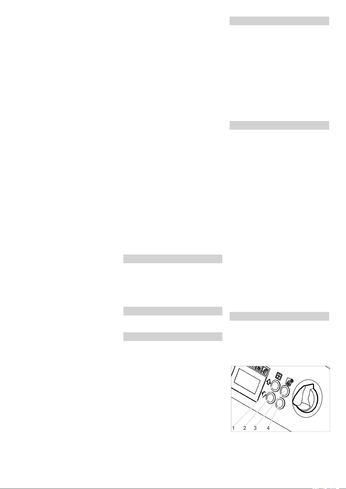
Bij het optreden van die symptomen het apparaat onmiddellijk uitschakelen en naar
buiten gaan, bij de verderzetting van het
werk de verluchtingsmaatregelen verbeteren of een beademingstoestel gebruiken.
Kooldioxide verzamelt zich op lager gelegen plaatsen. Verzameling verhinderen
door actieve verluchtingsmaatregelen.
Veiligheidsgegevensblad van de droogijsfabrikant in acht nemen.
Gevaar
Gevaar door gezondheidsschadelijke stoffen Indien bij de verwerking stof dat schadelijk is voor de gezondheid kan ontstaan,
moeten voor het begin van de werkzaamheden overeenkomstige veiligheidsmaatregelen getroffen worden.
Gevaar
Explosiegevaar!
Lichte metalen en ijzerhoudende onderdelen niet tegelijkertijd bewerken.
Indien afwisselend lichte metalen en ijzerhoudende onderdelen bewerkt worden,
moeten de werkruimte en de afzuiginrichting voor de bewerking van het andere materiaal gereinigd worden.
Gevaar door stofexplosie. Indien bij het
werk brandbaar stof ontstaat, moeten stofophopingen vermeden worden. Stof regelmatig verwijderen vooraleer kritische
hoeveelheden zijn ontstaan.
Bij het werken in kleine ruimten moet
gezorgd worden voor voldoende verluchting om de kooldioxideconcentratie
in de ruimte onder de gevaarlijke waarde te houden.
Reinigingsobject indien nodig vastzet-
ten.
Gevaar
Verwondingsgevaar door elektrostatische
ontladingen, beschadigingsgevaar voor
elektronische componenten. Bij het reinigen kan het reinigingsobject elektrisch geladen worden. Reinigingsobject elektrisch
aarden en aarding tijdens het volledige reinigingsproces behouden.
몇 Waarschuwing
Gevaar voor verwonding door struikelen.
Straalmiddelslang en stuurleiding zodanig
leggen dat tijdens het werk geen struikelgevaar bestaat.
Voorzichtig
Beschadigingsgevaar door vreemde voorwerpen die in het droogijsreservoir vallen.
Tijdens de werking het deksel van het
droogijsreservoir gesloten houden.
Aardingskabel elektrisch geleidend met
het reinigingsobject verbinden of reinigingsobject op een andere manier aarden.
Veiligheidskledij, veiligheidshand-
schoenen, nauwaansluitende veiligheidsbril en oorbescherming dragen.
Luchtdruktoevoer activeren.
Nood-stop-knop door draaien ontgren-
delen.
Bedrijfsmodus Luchtdrukstraal „1“ of
droogijsstraal „2“ instellen aan de schakelaar voor bedrijfsmodi van het spuitpistool.
Veilige standplaats kiezen en een goe-
de lichaamshouding aannemen om
door de reactiedruk van het spuitpistool
het evenwicht niet te verliezen.
Om het plotselinge optreden van een
terugslag te voorkomen kan een langzame stijging van de straaldruk worden
ingesteld (zie "Bediening/basisinstellingen" menupunt Softstart).
Beveiligingsknop van het spuitpistool
indrukken.
Droogijsstraal activeren door het bedie-
nen van de hendel van het spuitpistool
en reinigingsproces uitvoeren.
Waarschuwing
Bij het gebruik van het Advanced spuitpistool kan de toevoeging van droogijsbrokjes uit- en ingeschakeld worden met de
knop Droogijsdosering uit/in op het spuitpistool. Bij een uitgeschakelde dosering
brandt de knop rood, op het display wordt
„Ice off“ weergegeven.
Tevens kan bij het gebruik van het Advanced spuitpistool de straaldruk en de droogijshoeveelheid op het spuitpistool geregeld
worden.
Voorzichtig
Beschadigingsgevaar voor het doseerapparaat door vuil. Bij de straalwerking het
deksel van het droogijsreservoir gesloten
laten om het binnendringen van afgestraalde verontreinigingen te verhinderen.
Uitschakelen in noodgevallen
Hendel van het spuitpistool loslaten.
Noodstopknop indrukken.
De droogijsdosering wordt stilgelegd en de
luchtstroom uit de sproeier wordt onderbroken.
Luchtdruktoevoer onderbreken.
Inbedrijfname na noodstop
Nood-stop-knop door draaien ontgren-
delen.
Werking onderbreken
Hendel van het spuitpistool loslaten.
Bij pauzen kan het spuitpistool op de
houder aan het apparaat geplaatst worden.
Waarschuwing
Bij langdurige bedrijfsonderbrekingen kunnen de droogijsbrokjes in het droogijsreservoir samensmelten. Werk indien mogelijk
niet langer dan 20 minuten onderbreken.
Bij langere onderbrekingen moet het
droogijsreservoir leeggemaakt worden.
Condensaat aflaten
Een waterfascheider reinigt de naar het apparaat geleide perslucht. Daardoor verzamelt zich condensaat in de
waterfascheider, die af en toe leeggemaakt
moet worden.
Opvangbak onder de condensaataf-
voer zetten.
Drukontlastklep langzaam openen en
wachten tot het condensaat uit het apparaat is weggelopen.
Waarschuwing
Ter bescherming van het milieu moet het
condensaat conform de geldige bepalingen
worden weggedaan.
Statistiek-functie
Waarden opvragen
Apparaatschakelaar op „I“ stellen.
Toets statstiek even indrukken, de be-
drijfsduur wordt aangegeven.
t: Bedrijfsduur sinds de afgelopen reset.
T: Totale bedrijfsduur.
Toets statstiek even indrukken, de ver-
werkte droogijshoeveelheid wordt aangegeven.
m: Droogijshoeveelheid sinds de afgelopen reset.
M: Droogijshoeveelheid totaal.
Toets statstiek even indrukken, het ge-
middelde droogijsverbruik wordt aangegeven.
q: Gemiddeld droogijsverbruik sinds de
afgelopen reset.
Q: Gemiddeld droogijsverbruik totaal.
Waarden resetten
Sleutelschakelaar met de wijzers van
de klok draaien.
Toets statistiek gedurende 4 sec. in-
drukken.
Waarschuwing
De totale waarden kunnen niet worden gewist.
Basisinstellingen
Toetsen straaldruk verhogen en straal-
druk verlagen tegelijk indrukken en ingedrukt houden, sleutelschakelaar met
de wijzers van de klok draaien.
In de bedrijfsmodus Basisinstellingen hebben de toetsen de volgende functies:
1 Waarde verhogen
2 Waarde verlagen
3 Menupunt omhoog
4 Menupunt omlaag
58 NL
- 7
Page 59

Instelbereik
Menupunt
0, 1, 2, 3,
4, 5 seconden
Softstart
1, 2, 3, 4, 5
minuten
T_Dump
metric, imperial
Language
ON/OFF Sproeierverlichting (op-
Lighting
ON/OFF Demonstratiewerking:
Demo-Mode
Basisinstellingen sluiten
Sleutelschakelaar tegen de wijzers van
de klok draaien.
Beschrijving
Zacht opstarten, duur tot
de geselecteerde straaldruk is bereikt
Duur van de droogijs-ledigingsprocedure
Maateenheden
metric: kg/h, MPa
imperial: lbs, psi
tie) in-/uitschakelen
Bediening wordt gesimuleerd, perslucht- en
droogijsafgifte zijn geblokkeerd.
Buitenwerkingstelling
Gevaar
Gevaar van brandwonden door droog ijs.
Droog ijs heeft een temperatuur van -79 °C.
Droog ijs en koude onderdelen van het apparaat nooit onbeschermd aanraken. Veiligheidshandschoenen en veiligheidskledij
dragen.
Gevaar
Verwondingsgevaar door rondslingerende
droogijsbrokjes. Spuitpistool niet op personen richten. Derden verwijdern van de gebruiksplaats en ervoor zorgen dat tijdens
de werking geen persoon in de buurt kunnen komen (bijv. door afsluiting).
Luchtdruktoevoer sluiten.
Opvangbak onder de condensaataf-
voer zetten.
Drukontlastklep langzaam openen en
wachten tot het condensaat en de perslucht uit het apparaat zijn verwijderd.
Opvangbak onder de droogijsafvoer
plaatsen.
Toets Lediging droogijsreservoir in-
drukken en wachten tot het droogijsreservoir leeg is.
De droogijslediging stopt na de vooraf
ingestelde tijd (zie "Basisinstellingen").
Indien nodig de toets Lediging droogijsreservoir meerdere keren indrukken.
Waarschuwing
Ter bescherming van het milieu moet het
condensaat conform de geldige bepalingen
worden weggedaan.
Apparaatschakelaar op „0/OFF“ stellen.
Apparaat scheiden van de luchtdruk-
toevoerleiding.
Stekker uit het stopcontact trekken.
Aardkabel reinigen en oprollen.
Straalgoed volgens de plaatselijke
voorschriften verwijderen.
Vervoer
Gevaar
Ongevallengevaar door droogijsresten in
het apparaat. Voor het transport in gesloten
voertuigen moet het droogijs restloos uit
het apparaat verwijderd zijn om gevaren
van de meerijdende personen door kooldioxide te verhinderen.
Voor het transport alle stappen in het
hoofdstuk „Buitenwerkingstelling“ uitvoeren.
Apparaat op het transportvoertuig bren-
gen.
Remmen van de stuurrollen vergrende-
len.
Apparaat met spanriemen op het voer-
tuig bevestigen.
Opslag
Voorzichtig
Gevaar voor letsel en beschadiging! Het
gewicht van het apparaat bij opbergen in
acht nemen.
Het apparaat mag alleen binnen worden
opgeborgen.
Onderhoud en reparatie
Onderhoudsinstructies
Basisprincipe voor een gebruiksveilige installatie is het regelmatige onderhoud volgens het volgende onderhoudsplan.
Gebruik uitsluitend originele reserveonderdelen van de fabrikant of door hem aanbevolen onderdelen zoals
– Reserve- en slijtageonderdelen,
– Accessoires,
– Werkstoffen,
– Reinigingsmiddelen.
Gevaar!
Ongevallengevaar bij werkzaamheden aan
het apparaat. Voor werkzaamheden aan
het apparaat alle stappen van het hoofdstuk „Buitenwerkingstelling“ uitvoeren.
Gevaar
Gevaar van brandwonden door droogijs of
koude onderdelen van het apparaat. Bij
werkzaamheden aan het apparaat geschikte veiligheidskledij voor koude dragen of
droog ijs verwijderen en apparaat laten opwarmen.
Gevaar
Gevaar door volumetrische uitzetting en
brandwonden door koude.
Droogijs nooit in de mond nemen.
Voorzichtig
Beschadigingsgevaar. Spuitpistool niet
met oplosmiddel, benzine of oliehoudende
reinigingsmiddelen reinigen.
Onderhoudscontract
Om een betrouwbare werking van de installatie te garanderen, raden u aan om
een onderhoudscontract af te sluiten. Gelieve contact op te nemen met uw betreffende Kärcher-klantenservice.
Onderhoudsschema
Dagelijks voor het bedrijfsbegin
Spuitmiddelslang zorgvuldig controle-
ren op scheuren, knikplaatsen en andere beschadigingen. Zachte plaatsen in
de slang wijzen op slijtage aan de binnenkant van de slang. Defecte of versleten slang vervangen door een
nieuwe slang.
Elektrische kabels en stekkers contro-
leren op beschadiging. Defecte onderdelen door de klantendienst laten
vervangen.
Alle 100 bedrijfsuren
Koppelingen aan spuitmiddelslang, aan
het apparaat en aan het spuitpistool
controleren op beschadiging en slijtage. Defecte slang vervangen, defecte
koppelingen aan apparaat of spuitpistool laten vervangen door de klantendienst.
Doseerapparaat op schade en ondicht-
heid controleren. Indien schade/ondichtheden vastgesteld worden,
klantendienst informeren.
Controleren of de bevestigingsdoppen
van de achterste wielen goed zitten.
Alle 500 uren of jaarlijks
Apparaat laten controleren door de
klantendienst.
Alle 2 jaar
Spuitmiddelslang minimum alle 2 jaar
vernieuwen.
Apparaat openen
Voor de uitvoering van enkele onderhoudswerkzaamheden moeten de zijbekledingen
van het apparaat verwijderd worden:
1 Snelsuiting
2 Zijbekleding
Snelsluitingen tegen de wijzers van de
klok openen.
Zijpaneel wegnemen.
- 8
59NL
Page 60

Onderhoudswerkzaamheden
Hulp bij storingen
Filterelement in de waterafscheider vervangen
1 Schroef
2 Onderste deel
3 Moer
4 Schijf
5 Filterelement
6 Bovenste deel
4 schroeven losdraaien.
Onderste deel wegnemen.
Moer losschroeven.
Schijf wegnemen.
Filterelement wegnemen en door een
nieuw filterelement vervangen.
Waterafscheider in omgekeerde volgor-
de opnieuw monteren.
Controles
Volgens BGV D 26 moet het apparaat door
een expert onderworpen worden aan de
volgende controles. De resultaten van de
controle moeten in een verslag opgetekend
worden. Het verslag moet door de exploitant van het apparaat bewaard worden tot
de volgende controle.
Na een onderbreking van meer dan één
jaar
Apparaat controleren op reglementaire
toestand en functionaliteit.
Na wijziging van de plaats van opstelling
Apparaat controleren op reglementaire
toestand, functionaliteit en opstelling.
Na herstellingswerkzaamheden of veranderingen die de bedrijfsveiligheid
kunnen beïnvloeden
Apparaat controleren op reglementaire
toestand, functionaliteit en opstelling.
Gevaar!
Ongevallengevaar bij werkzaamheden aan
het apparaat. Voor werkzaamheden aan
het apparaat alle stappen van het hoofdstuk „Buitenwerkingstelling“ uitvoeren.
Gevaar
Gevaar van brandwonden door droogijs of
koude onderdelen van het apparaat. Bij
werkzaamheden aan het apparaat geschikte veiligheidskledij voor koude dragen of
droog ijs verwijderen en apparaat laten opwarmen.
Gevaar
Gevaar door volumetrische uitzetting en
brandwonden door koude.
Droogijs nooit in de mond nemen.
60 NL
- 9
Page 61

Storingen met weergave op het display
Displayweergave
E001 KL stuurspanning
E002 KL noodstop brandt
E003 KL perslucht brandt
E004 KL dosering brandt
E005 KL spuitpistool brandt
E006 KL spuitpistool brandt
E007 KL perslucht brandt
E008 KL spuitpistool brandt
Controlelampje (KL) Mogelijke oorzaak Oplossing Door wie
brandt rood
rood
rood
rood
rood
rood
rood
oranje
Stuurspanning te laag Apparaat uitschakelen, kort wachten. Apparaat opnieuw in-
schakelen
Stopcontact laten controleren.
Wanneer de foutcode opnieuw verschijnt, contact opnemen
met de Kärcher-klantendienst
Noodstopknop is ingedrukt Nood-stop-knop door draaien ontgrendelen. Bediener
Druk van de persluchtvoorziening te
laag
Storing in de doseerunit Apparaat uitschakelen, kort wachten. Apparaat opnieuw in-
Verbinding tussen apparaat en
spuitpistool gestoord.
Kortsluiting in het spuitpistool of de
stuurkabel
Storing aan de perslucht-regelklep Klantendienst raadplegen. Bediener
Hendel van het spuitpistool werd tijdens het inschakelen of bij het ontgrendelen van de noodstoptoets
bediend
Druk verhogen.
Apparaat uitschakelen, kort wachten. Apparaat opnieuw inschakelen
schakelen
Wanneer de foutcode opnieuw verschijnt, contact opnemen
met de Kärcher-klantendienst
Correcte verbinding van de koppelingen in de stuurleiding
controleren.
Stuurkabels op beschadiging controleren.
Spuitpistool of straalslang met stuurkabel vervangen. Bediener
Hendel van het spuitpistool loslaten. Bediener
Bediener
Bediener
Bediener
Bediener
Storingen zonder weergave op het display
Storing Mogelijke oorzaak Oplossing Door wie
Geen displayweergave
ondanks een ingeschakelde hoofdschakelaar
Geen luchtdrukstraal ondanks ingetrokken hendel
Luchtdrukstraal te zwak Spuitdruk te laag ingesteld Spuitdruk hoger instellen. Bediener
Geen droogijsbrokjes in
de luchtdrukstraal
Stekker niet in het stopcontact gestoken. Netstekker in een stopcontact steken. Bediener
Zekering F1 is in werking getreden Zijpaneel wegnemen en zekering F1 door indrukken ont-
grendelen.
Luchtdruktoevoer heeft te weinig druk Druk controleren. Bediener
Spuitdruk te laag ingesteld Spuitdruk hoger instellen. Bediener
Stroomtoevoer onderbroken Stroomtoevoer controleren. Controlelampje „Apparaat
in“ moet groen branden.
Noodstopknop is ingedrukt Noodstoptoets door draaien ontgrendelen. Controle-
lampje „Apparaat in“ moet groen branden.
Stuurleiding niet correct aangesloten Verbinding tussen stuurleiding en spuitpistool alsook
tussen stuurleiding en apparaat controleren.
Stuurleiding is defect Spuitmiddelslang vervangen. Bediener
Luchtdruktoevoer heeft te weinig druk of volume
van de compressor te laag.
Filterelement in de waterafscheider verstopt. Filterelement in de waterafscheider vervangen. Bediener
Spuitmiddelslang of spuitpistool verstopt Spuitmiddelslang en spuitpistool laten ontdooien en ver-
Droogijsdosering uitgeschakeld (alleen Advanced
spuitpistool), knop droogijsdosering in/uit op het
spuitpistool brandt rood, displayweergave „Ice off“.
Droogijsreservoir leeg Droogijsreservoir vullen Bediener
Droog ijs samengesmolten Droogijsreservoir leegmaken en vullen met verse droog-
Triller aan het droogijsreservoir werkt niet Klantendienst raadplegen. Bediener
Aandrijfmotor van het doseerapparaat overbelast Doseerapparaat laten ontdooien Bediener
Luchtdrukuitlaat in het droogijsreservoir Drukcompensatieleiding in het doseerapparaat reinigen. Klantendienst
Doseerschijf in de doseereenheid defect Doseerschijf vervangen. Klantendienst
Druk en volume controleren. Bediener
stopping verhelpen. Werkdruk verhogen en / of droogijs-
dosering verlagen.
Knop Droogijsdosering op het spuitpistool Advanced in-
drukken.
ijspellets.
Bediener
Bediener
Bediener
Bediener
Bediener
Bediener
Bediener
- 10
61NL
Page 62

Technische gegevens
Elektrische aansluiting
Spanning V 220...240
Stroomsoort 1~
Frequentie Hz 50
Aansluitvermogen kW 0,6
Veiligheidsklasse IPX4
FI-veiligheidsschakelaar delta I in A 0,03
Lekstroom, type. mA 7,5
Luchtdruk
Slang-nominale wijdte duim 3/4
Toevoerdruk (max.) MPa (bar) 1,6 (16)
Toevoerdruk (min.) MPa (bar) 0,2 (2)
3
Persluchtverbruik m
Luchtdrukkwaliteit droog, olievrij
Capaciteit
Spuitdruk (max.) MPa (bar) 1,6 (16)
Diameter van de droogijspellets (max.) mm 3
Droogijsverbruik kg/u 30...120
Afmetingen
Inhoud droogijsreservoir kg 40
Breedte mm 716
Diepte mm 850
Hoogte mm 1102
Gewicht met accessoires kg 101,5
Gewicht, bedrijfsklaar, met gevuld droogijsreservoir kg 140
Bandendruk (max.) MPa (bar) 0,2 (2)
Gewicht spuitinrichting (spuitmiddelslang, spuitpistool, gereedschaptas) kg 10
Reactiedruk van het spuitpistool (max.) N 100
Draaimoment van het spuitpistool (max.), alleen bij gebogen sproeier N 40
Geluidsdrukniveau L
Geluidsvermogensniveau L
pA
WA
Onzekerheid K dB(A) 5
Apparaattrillingen
Spuitpistool m/s² 1,2
Spuitmiddelslang m/s² 1,2
/min 2...12
dB(A) 114
dB(A) 136
62 NL
- 11
Page 63

Accessoires
Veiligheidskledij
Veiligheidsbril, anti-beslaan, onderdele-nr.:
6.321-208.0
Beschermende handschoenen tegen koude met anti-slipprofiel, categorie III conform
EN 511, onderdelen-nr.: 6.321-210.0
Gehoorbescherming met hoofdbeugel, onderdele-nr.: 6.321-207.0
Spuitinrichting
Rondstraalspuitkop, L, lang
Onderdelen-nr.: 4.574-019.0
Rondstraalspuitkop, L, extra lang
Onderdelen-nr.: 4.574-016.0
Rondstraalspuitkop, M, lang
Onderdelen-nr.: 4.574-018.0
Rondstraalspuitkop, M, kort
Onderdelen-nr.: 4.130-418.0
Rondstraalspuitkop, L, kort
Onderdelen-nr.: 4.130-419.0
Vlakstraalsproeier
Onderdelen-nr.: 4.130-423.0
Vlakstraalsproeierelement, M, 6 mm
Onderdelen-nr.: 4.130-421.0
Vlakstraalsproeierelement, L, 8mm
Onderdelen-nr.: 4.130-420.0
Vlakstraalsproeierelement, XL, 10 mm
Onderdelen-nr.: 4.130-422.0
Garantie
In elk land gelden de door onze bevoegde
verkoopmaatschappij uitgegeven garantievoorwaarden. Eventuele storingen aan het
apparaat herstellen wij binnen de garantieperiode kostenloos voor zover een materiaal- of productiefout de oorzaak is. Voor
garantieaanspraken wendt u zich met uw
aankoopbewijs tot uw handelaar of de
dichtstbijzijnde, bevoegde klantendienst.
EG-conformiteitsverklaring
Hierbij verklaren wij dat de hierna vermelde
machine door haar ontwerp en bouwwijze
en in de door ons in de handel gebrachte
uitvoering voldoet aan de betreffende fundamentele veiligheids- en gezondheidseisen, zoals vermeld in de desbetreffende
EG-richtlijnen. Deze verklaring verliest
haar geldigheid wanneer zonder overleg
met ons veranderingen aan de machine
worden aangebracht.
Product: Droogijsstraalapparaat
Type: 1.574-xxx
Van toepassing zijnde EG-richtlijnen
2006/42/EG (+2009/127/EG)
2004/108//EG
Toegepaste geharmoniseerde normen
EN 55014–1: 2006+A1: 2009+A2: 2011
EN 55014–2: 1997+A1: 2001+A2: 2008
EN 60204–1
EN 61000–3–2: 2006+A1: 2009+A2: 2009
EN 61000–3–3: 2008
EN 62233: 2008
Toegepaste landelijke normen
GS-STE-13 (in aansluiting)
Hoekstraalpijp 90°
Onderdelen-nr.: 4.321-203.0
Hoekstraalpijp 105°
Onderdelen-nr.: 4.321-204.0
Sproeierverlenging, 300 mm lang
Onderdelen-nr.: 4.130-417.0
Handgreep
Onderdelen-nr.: 6.321-206.0
Scrambler
Onderdelen-nr.: 4.110-015.0
Werkverlichting
Onderdelen-nr.: 2.815-422.0
Beschermslang voor straalpijp, kunststof,
100 m
Onderdelen-nr.: 6.667-214.0
De ondergetekenden handelen in opdracht
en met volmacht van de bedrijfsleiding.
CEO
Gevolmachtigde voor de documentatie:
S. Reiser
Alfred Kärcher GmbH & Co. KG
Alfred Kärcher-Str. 28 - 40
71364 Winnenden (Germany)
Tel.: +49 7195 14-0
Fax: +49 7195 14-2212
Winnenden, 2013/02/01
Head of Approbation
- 12
63NL
Page 64

Antes del primer uso de su apa-
rato, lea este manual original,
actúe de acuerdo a sus indicaciones y
guárdelo para un uso posterior o para otro
propietario posterior.
Índice de contenidos
Protección medioambiental ES . . 1
Indicaciones de seguridad . ES . . 1
Uso previsto . . . . . . . . . . . . ES . . 2
Función . . . . . . . . . . . . . . . . ES . . 2
Elementos de mando . . . . . ES . . 3
Puesta en marcha. . . . . . . . ES . . 4
Manejo . . . . . . . . . . . . . . . . ES . . 6
Puesta fuera de servicio . . . ES . . 8
Transporte. . . . . . . . . . . . . . ES . . 8
Almacenamiento . . . . . . . . . ES . . 8
Mantenimiento y cuidado . . ES . . 8
Ayuda en caso de avería . . ES . . 9
Datos técnicos . . . . . . . . . . ES . 12
Accesorios . . . . . . . . . . . . . ES . 13
Garantía . . . . . . . . . . . . . . . ES . 13
Declaración de conformidad CE ES . 13
Protección medioambiental
Los materiales de embalaje son reciclables. Por favor, no tire el embalaje
a la basura doméstica; en vez de ello,
entréguelo en los puntos oficiales de
recogida para su reciclaje o recuperación.
Los aparatos viejos contienen materiales valiosos reciclables que deberán ser entregados para su
aprovechamiento posterior. Evite el
contacto de baterías, aceites y materias semejantes con el medioambiente. Por este motivo, entregue los
aparatos usados en los puntos de recogida previstos para su reciclaje.
Indicaciones sobre ingredientes
(REACH)
Encontrará información actual sobre los ingredientes en:
www.kaercher.com/REACH
Indicaciones de seguridad
Sólo pueden operar el aparato aquellas
personas que hayan leído y entendido este
manual de instrucciones. Se debe prestar
especial atención a las indicaciones de seguridad.
Guardar el manual de instrucciones
para que esté siempre a disposición del
operario.
Niveles de peligro
Peligro
Para un peligro inminente que acarrea lesiones de gravedad o la muerte.
몇 Advertencia
Para una situación que puede ser peligrosa, que puede acarrear lesiones de gravedad o la muerte.
Precaución
Para una situación que puede ser peligrosa, que puede acarrear lesiones leves o
daños materiales.
Símbolos en el aparato
Peligro
Riesgo de lesiones causadas por pellets de
hielo seco en movimiento. No apuntar a
personas con la pistola de chorreo. Alejar
a terceras personas del lugar de aplicación
y mantenerlas alejadas mientras el aparato
esté en funcionamiento (por ejemplo mediante un bloqueo).
Mientras esté en funcionamiento no tocar
la boquilla ni el chorro de hielo seco.
Peligro
Riesgo de asfixia por dióxido de carbono.
Los pellets de hielo seco está compuestos
de dióxido de carbono sólido. Cuando se
opera el aparato aumenta el contenido de
dióxido de carbono en el aire del lugar de
trabajo. Ventilar bien el lugar de trabajo,
utilizar si es necesario un aparato de aviso
a personas. Síntomas de una alta concentración de dióxido de carbono en el oxígeno:
– 3...5%: dolor de cabeza, frecuencia
respiratoria alta.
– 7...10%: dolor de cabeza, nauseas, po-
sible pérdida de consciencia.
Si se producen estos síntomas, apagar inmediatamente el aparato y salir al aire libre, antes de continuar el trabajo, mejorar
las medidas de ventilación o utilizar un
aparato de respiración artificial.
Respetar la hoja de datos de seguridad del
fabricante de hielo seco.
Peligro
Riesgo de lesiones causadas por descargas electroestáticas, riesgo de daños causados por módulos electrónicos. Durante el
proceso de limpieza, el objeto a limpiar se
puede cargar de electricidad. Poner a tierra
el objeto a limpiar y mantener la toma a tierra durante todo el proceso de limpieza.
Peligro
Peligro de lesiones por descarga eléctrica.
Antes de abrir el armario de control desenchufar el aparato.
Peligro
Peligro de que se produzcan quemaduras
por frío. El hielo seco tiene una temperatura de -79 °C. No tocar el hielo seco ni las
piezas del aparato frías sin protección.
Peligro
Riesgo de lesiones causadas por pellets de
hielo seco o partículas de suciedad en movimiento. Utilizar gafas protectoras bien
ajustadas.
Peligro de daños del aparato auditivo. Utilizar orejeras.
El equipamiento de protección no puede
obstaculizar el contacto visual ni la comunicación con el entorno de trabajo.
Peligro
Riesgo de lesiones causadas por pellets de
hielo seco o partículas de suciedad en movimiento.
Riesgo de lesiones al tocar las piezas frías
del aparato.
Utilizar guantes de seguridad de acuerdo
con EN 511 y ropa protectora de manda
larga.
Indicaciones generales de
seguridad
Peligro
Riesgo de lesiones causadas por un aparato en funcionamiento sin vigilancia. Antes
de proceder a realizar trabajos en el aparato, desenchufar el aparato de la toma de
corriente.
Peligro
Peligro de lesiones por descarga eléctrica.
Antes de abrir el armario de control desenchufar el aparato.
Peligro
Peligro de quemaduras por frío causadas
por el hielo seco o las piezas del aparato
frías. Al trabajar con el aparato, utilizar
ropa protectora contra el frío o eliminar el
hielo seco y dejar calentar el aparato.
Peligro
Peligro por la extensión volumétrica y quemadura por frío.
No llevar nunca el hielo seco a la boca.
64 ES
- 1
Page 65

몇
Advertencia
Riesgo de accidentes provocados por la
fuerza de retroceso de la pistola de chorreo. Buscar una posición segura antes de
pulsar la palanca de disparo de la pistola
de chorreo y sujetarla bien.
Peligro
Riesgo de lesiones causadas por objetos
en movimiento. Fijar los objetos a limpiar
de poco peso para evitar que el chorro de
aire seco de los lleve.
몇 Advertencia
Riesgo de aplastamiento por el dispositivo
de dosificación. Antes de retirar la chapa
protectora del recipiente de hielo seco,
desenchufar el aparato de la toma de corriente.
Normativas y directivas
Durante el funcionamiento de esta instalación deben observarse las siguientes normas y directivas vigentes en la República
Federal de Alemania (adquiribles de la editorial Carl Heymanns Verlag KG, Luxemburger Straße 449, 50939 Köln
(Alemania)):
– BGV D 26 trabajos de arenado
– Modo de ejecución sobre BGV D 26
– BGR 117 trabajos en lugares estrechos
– BGR 139 Normas de seguridad para
personas - Instalaciones de señales de
emergencia.
– BGR 189 uso de ropa protectora
– BGR 195 uso de guantes de seguridad
– BGR 500 Operar elementos de trabajo
– BGI 534 trabajos en lugares estrechos
– BGI 836 detector-avisador de gas
Respetar las directrices y normativas de
seguridad nacionales así como las normativas nacionales de los sindicatos y sociedades especializadas.
Dispositivos de seguridad
Uso previsto
El aparato sirve para eliminar suciedades
con los pellets de hielo seco que son acelerados por un corro de aire.
No se puede operar el aparato en un ambiente donde exista riesgo de explosiones.
Sólo se puede utilizar pellets de hielo seco
como producto abrasivo. El uso de otro tipo
de productos abrasivos puede provocar
daños al aparato.
Función
El aire comprimido pasa a la pistola de chorreo a través de una válvula reguladora de
presión. Al pulsar la palanca de disparo de
la pistola de chorreo se abre la válvula y el
chorro de aire sale de la pistola. Adicionalmente se dosifican pellets de hielo seco en
el chorro de aire a través del dispositivo dosificador. La dosificación se puede desconectar con el interruptor de
funcionamiento. Los pellets de hielo seco
chocan contra la superficie a limpiar y eliminan la suciedad. Debido a que los pellets
de hielo seco están a una temperatura de 79 ºC, también se crean tensiones térmicas
entre la suciedad y el objeto a limpiar, lo
que también ayuda a soltar la suciedad. El
hielo seco también se convierte inmediatamente al chocar en dióxido de carbono en
forma de gas y precisa así 700 veces más
volumen. De esta forma se elimina la suciedad bajo el hielo seco.
Durante el funcionamiento de chorro, un vibrador situado en el recipiente de hielo
seco se encarga de alimentar pellets de
hielo seco de forma continuada.
Tecla de desconexión de emergencia
Si se pulsa el pulsador de paro de emergencia se para la dosificación de hielo seco
y se interrumpe el flujo de aire de la boquilla.
Desconectar en caso de
emergencia
Soltar la palanca de disparo de la pisto-
la de chorreo.
Pulsar la tecla de desconexión de
emergencia
Se para la dosificación de hielo seco y se
interrumpe el flujo de aire de la boquilla.
Interrumpir el suministro de aire compri-
mido.
- 2
65ES
Page 66

Elementos de mando
aparato
1 Fusible F1, debajo del panel lateral
2 Toma de aire comprimido
3 Salida de condensado
4 Estribo de empuje
5 Cierre, maleta
6 Soporte para la pistola de chorreo
7 Maleta para accesorios
8 Desbloqueo, fijación de la maleta
9 Asa, maleta
10 Portacables
11 Válvula de descarga de presión, vacia-
do de condensado separador de agua
12 Mango para el transporte, estribo de
protección
13 Cable de alimentación con enchufe de
clavija de red
14 Salida de hielo seco, para vaciar el re-
cipiente
15 Rodillo-guía con freno de estaciona-
miento
16 Acoplamiento producto abrasivo-man-
guera
17 Cuerda de toma a tierra con borne
18 Acoplamiento línea piloto
19 Panel de control
20 Depósito para accesorios
21 Tapa protectora del recipiente de hielo
seco
Panel de control Pantalla
1 Tecla estadística, restablecer el conta-
dor
2 Tecla Aumentar presión de chorro
3 Tecla Aumentar dosificación hielo seco
4 Interruptor del aparato
5 Tecla de desconexión de emergencia
6 Interruptor de llave
7 Tecla Reducir dosificación hielo seco
8 Tecla Reducir presión de chorro
9 anuncio
10 Tecla Vaciado del recipiente de hielo
seco
1 Piloto de control Tensión de control
verde: Tensión de control en orden
rojo: Tensión de control demasiado
baja
amarillo: Vaciado del recipiente de hie-
lo seco activo
2 Piloto de control Desconexión de emer-
gencia
rojo: Botón de desconexión de emer-
gencia pulsado
verde: Botón de desconexión de emer-
gencia no pulsado
3 Piloto de control Aire comprimido
verde: Presión correcta
naranja: no se ha alcanzado la presión
de chorro seleccionada
rojo: Presión demasiado baja (inferior a
0,15 MPa/1,5 bar)
66 ES
- 3
Page 67

4 Piloto de control Dispositivo de dosifica-
ción
verde: Accionamiento correcto
rojo: Avería en accionamiento
5 Piloto de control Pistola de chorro
verde: Pistola de chorro correcta
naranja: Palanca de disparo de la pisto-
la de chorro accionado durante la conexión
rojo: Pistola de chorro desenganchada
o conducto de control dañado
6 Campo indicador
Dispositivo de chorro
Pistola de chorreo
1 boquilla
2 Pistola de chorreo
3 Acoplamiento producto abrasivo-man-
guera
4 Acoplamiento línea piloto
5 Palanca de seguro
6 Palanca de disparo
7 Interruptor de modo de funcionamiento
Posición "1": Chorro de aire comprimi-
do
Posición "2": Chorro de hielo seco (aire
comprimido y pellets de hielo seco)
Pistola pulverizadora Advanced (opcional)
7 Tecla Conectar/desconectar dosifica-
ción hielo seco
Se ilumina en rojo si la dosificación de
hielo seco está desconectada
8 Tecla Aumentar dosificación hielo seco
9 Tecla Aumentar presión de chorro
10 Tecla Reducir presión de chorro
11 Tecla Reducir dosificación hielo seco
Maleta para accesorios
La maleta sirve para almacenar las boquillas y las herramientas correspondientes.
1 Cierre
2 Asa de transporte
3 Desbloqueo
Abrir la maleta
Abra las tapas.
Girar la tapa hacia abajo.
Precaución
Riesgo de daños, no colocar objetos pesados sobre la tapa abierta.
Separar la maleta del aparato.
Presionar los desbloqueos y extraer la
maleta.
Colocar la maleta en el aparato.
Girar la maleta con los cierres hacia
arriba.
Colocar un lateral de la maleta en el so-
porte y encajar.
Presionar la maleta contra el aparato y
encajar el soporte opuesto.
Unir y asegurar la manguera de produc-
to abrasivo con el aparato.
Unir y asegurar la pistola de chorreo
con la manguera de producto abrasivo.
Conectar el tubo de control con el apa-
rato.
Conectar el tubo de control con la pisto-
la de chorreo.
Boquillas
Nota
La selección de la boquilla depende del
material del objeto a limpiar y de la suciedad.
El volumen de aire disponible también tiene gran influencia a la hora de elegir la boquilla.
Todas las boquillas se atornillan a la rosca
de la pistola de chorreo sin necesidad de
herramientas. Las superficies de llave colocadas en la boquilla sirven para aflojar boquillas ajustadas con una llave de boca.
Precaución
Peligro de soldadura en frío. Untar con la
grasa suministrada la rosca de la boquilla
antes del montaje.
Selección de boquilla
La siguiente tabla indica el consumo de
aire con las diferentes boquillas.
Cada boquilla está marcada con un índice
de caudal de aire de XS - XXL.
Con la tabla de boquillas se puede calcular
el consumo de aire para cada boquilla.
1 boquilla
2 Pistola de chorreo
3 Palanca de disparo
4 Cabezal de seguro
5 Acoplamiento producto abrasivo-man-
guera
6 Acoplamiento línea piloto
Puesta en marcha
Peligro
Riesgo de lesiones causadas por pellets de
hielo seco en movimiento.
Examinar el estado de todos los módulos
eléctricos al preparar el aparato, especialmente la manguera del producto abrasivo.
Sustituir los módulos eléctricos dañados
por otros en perfecto estado.
Limpiar los módulos sucios y comprobar si
funcionan correctamente.
Colocar el aparato sobre una superficie
horizontal y plana y bloquear el freno de
estacionamiento de las ruedas girato-
rias.
Nota:
Para proteger contra el desgaste y la suciedad, se puede revestir la manguera de producto abrasivo con una manguera
protectora. Si es necesario, desplazar la
manguera protectora antes de conectar por
encima de la manguera de producto abrasivo.
- 4
67ES
Page 68

Agresividad de
muy baja baja media alta muy alta
arenado
Presión (bar) 2 3 4 5 6 7 8 9 10 11 12 13 14 15 16
Tamaño de la bo-
quilla
Rendimiento de superficie
XS Ø5 mm 0,40 0,70 0,90
S Ø6 mm 0,70
M Ø7 mm 0,93
L Ø8 mm
XL Ø9 mm
XXL Ø10 mm
1,05 1,45 1,80 2,07 2,40 2,78 3,14 3,48 3,78 4,13 4,35 4,70 5,10 5,40
1,38 1,85 2,28 2,64 3,05 3,63 4,03 4,57 4,80 5,30 5,80 6,22 6,65 7,15
1,09 1,64 2,26 2,78 3,20 3,79 4,40 4,95 5,45 5,90 6,40 7,15 7,67 8,15 8,80
1,50 2,16 2,88 3,50 4,03 4,60 5,41 6,01 6,53 7,27 8,08 8,70 9,28 9,80 10,40
1,52 2,20 2,97 3,66 4,27 5,00 5,82 6,52 7,40 8,00 8,90 9,50 10,05 10,70 11,30
Consumo de aire en m
1,10 1,30 1,60 1,80 2,00 2,30 -- -- -- -- -- --
3
/min
m3/min
...1 Red de aire comprimido
doméstico industrial
Compresor básico
p.ej. Käser M 17, Compair C 14
1...2 Red de aire comprimido
doméstico industrial
compresor pequeño
p.ej. Käser M 31, Compair C 20GS
2...3 compresor medio
3...5
p.ej. Käser M 57, Compair C 35
5...7 compresor medio
p.ej. Käser M 80, Compair C 55
7...10 compresor grande
p.ej. Käser M 122, Compair C 105
10... compresor muy grande
p.ej. Käser M 250, Compair C 200
Boquilla de chorro redonda
Además de la boquilla de chorro redonda
suministrada, se dispone de otras boquillas
de chorro redondas con diferentes diámetros.
Boquilla de chorro plano
1 Difusor
2 tuerca de racor
3 Inserto de boquilla
La boquilla de chorro plano está compuesta de inserto de boquilla y difusor. Se dispone de insertos de boquilla con diferentes
diámetros.
Colocar el inserto de boquilla sobre la
tubuladura roscada de la pistola de
chorreo y ajustar con la mano.
Colocar el difusor sobre el inserto de
boquilla.
Girar el difusor de modo que el chorro
plano vaya en la dirección deseada a la
pistola de chorreo.
Ajustar la tuerca de racor manualmen-
te.
Scrambler (accesorios)
El scrambler tritura los pellets de hielo seco
y se monta entre la pistola de chorreo y la
boquilla.
La orientación de las 4 placas agujereadas
en el scrambler determina el grado de pulverización.
Seleccionar el grado de pulverización:
1 unión roscada
2 Depósito
3 Plancha agujereada
Desenroscar la rosca.
Extraer el depósito con las placas de
agujeros.
1 Boquilla de chorro redondo, corta
2 Boquilla de chorro redondo, larga
3 Boquilla de chorro redondo, extra larga
Colocar la boquilla de chorro redonda
sobre la tubuladura roscada de la pistola de chorreo y ajustar con la mano.
68 ES
Colocar las placas de agujeros en el
depósito como se indica más arriba (3
posibilidades). Las medidas de la imagen se refieren al tamaño de los orificios de paso.
Colocar el depósito con las placas de
agujeros en el scrambler.
Enroscar y apretar la rosca.
- 5
Page 69

Prolongación de la boquilla (accesorios)
Se puede colocar una prolongación entre
la pistola de chorreo y la boquilla.
Lanza de agua angular (accesorio)
Se coloca una lanza de agua angular entre
la pistola pulverizadora y la boquilla.
1 Lanza de agua angular 105°
2 Lanza de agua angular 90º
몇 Advertencia
Peligro de lesiones. Si se utiliza una lanza
de agua acodada, a la fuerza de retroceso
se sumará un par de torsión a la pistola pulverizadora. Sujete bien la pistola pulverizadora.
Iniciar el trabajo con una presión de chorro
reducida y de ser necesario ir aumentándolo.
Empuñadura (accesorios)
La empuñadura se puede fijar en la prolongación.
Iluminación de trabajo (accesorios)
(solo para la pistola pulverizadora Advanced)
La iluminación de trabajo se coloca entre la
pistola de chorro y la boquilla. En el capítulo "Manejo/ajustes básicos" se describe la
conexión y desconexión.
Conectar el aire comprimido
Nota
Para un funcionamiento sin averías, el aire
comprimido tiene que tener un contenido
de humedad bajo. El aire comprimido no
debe tener aceite, ni suciedad u objetos extraños.
El compresor tiene que estar equipado al
menos con post-refrigerador, separador de
aceite y agua.
Cerrar la válvula de descarga de pre-
sión.
Conectar la tubería de aire comprimido
a la conexión de aire comprimido del
aparato.
La presión de suministro máxima permitida de 1,6MPa (16 bar) no debe ser
excedida.
Establecimiento de la conexión a
red
Peligro
Peligro por descarga eléctrica.
La toma de corriente usada debe estar instalada por un electricista y cumplir la norma
CEI 60364-1.
El aparato tiene que estar asegurado con un interruptor de protección FI tipo B, de 30 mA.
Comprobar si la conexión a red del aparato
está en perfecto estado antes de cada
puesta en funcionamiento. No poner en
funcionamiento el aparato si el cable está
dañado. Un electricista debe cambiar el
cable dañado.
El cable alargador tiene que tener un contactor IPX4 y el modelo de cable tiene que
cumplir al menos H 07 RN-F 3G1,5.
Enchufar la clavija de red a una toma
de corriente.
Manejo
Rellenar hielo seco
Peligro
Peligro de que se produzcan quemaduras
por frío. El hielo seco tiene una temperatura
de -79 °C. No tocar el hielo seco ni las piezas
del aparato frías sin protección. Utilizar guantes de seguridad y ropa protectora.
Abrir la tapa del recipiente de hielo seco.
Comprobar si en el recipiente de hielo
seco hay objetos extraños o condensado, extraer el objeto extraño y el condensado.
Rellenar el recipiente con pellets de hielo
seco.
Precaución
Se corre el riesgo de dañar el aparato. Solo
se puede utilizar pellets de hielo seco como
producto abrasivo. El uso de otro tipo de
productos abrasivos puede provocar la
pérdida de la garantía.
Cerrar la tapa del recipiente de hielo se-
co.
Nota
Para evitar averías provocadas por pellets
de hielo seco apelmazados, se recomienda
usar totalmente el contenido del recipiente
de hielo seco antes de rellenar de nuevo
con hielo seco. Antes de realizar largas
pausas en el funcionamiento, operar el
aparato hasta que el recipiente de hielo
seco esté vacío o vaciar el recipiente con la
función Vaciado de hielo seco.
Configuraciones
Nota
Las configuraciones dependen del material
del objeto a limpiar y de la suciedad.
El pulsador de parada de emergencia,
se desbloquea girándolo.
Colocar el interruptor principal en la po-
sición "I".
Girar el interruptor de llave en el sentido
de las agujas del reloj.
Configure la presión de chorro con las
teclas Aumentar/reducir la presión de
chorro.
Nota
Cuanto más alta sea la presión de chorro,
mayor (más agresivo) será el efecto de limpieza.
Configure la dosificación de hielo seco
con las teclas Aumentar/reducir la dosificación de hielo seco.
Gire el interruptor de llave en el sentido
contrario a las agujas del reloj y quitar
la llave.
Mediante el cierre automático del orificio de la llave se evitará que entre suciedad durante el funcionamiento.
Con la llave quitada, el aparato está
asegurado contra desajustes de las
configuraciones y restablecimientos de
los valores de estadística.
Funcionamiento
Realizar trabajos de mantenimiento
"diariamente antes de comenzar el funcionamiento" (véase aparato "Mantenimiento y cuidados").
Peligro
Riesgo de lesiones causadas por pellets de
hielo seco en movimiento. No apuntar a
personas con la pistola de chorreo. Alejar
a terceras personas del lugar de aplicación
y mantenerlas alejadas mientras el aparato
esté en funcionamiento (por ejemplo mediante un bloqueo).
Mientras esté en funcionamiento no tocar
el orificio de la boquilla ni el chorro de hielo
seco.
Antes de separar la conexión entre la pistola de chorreo y la manguera del producto
abrasivo y entre la manguera de producto
abrasivo y el aparato, es imprescindible
bloquear el suministro de aire comprimido,
dejar al aparato sin presión y desenchufar
el aparato.
Bloquear el área de trabajo para evitar
que entren personas durante el funcionamiento.
- 6
69ES
Page 70

Peligro
Riesgo de asfixia por dióxido de carbono.
Los pellets de hielo seco están compuestos de dióxido de carbono sólido. Cuando
se opera el aparato aumenta el contenido
de dióxido de carbono en el aire del lugar
de trabajo. Ventilar bien el puesto de trabajo, utilizar un dispositivo de advertencia de
personas o mascarillas.
Síntomas de una concentración de dióxido
de carbono alta en el aire que se respira:
– 3...5%: dolor de cabeza, frecuencia
respiratoria alta.
– 7...10%: dolor de cabeza, nauseas, po-
sible pérdida de consciencia.
Si se producen estos síntomas, apagar inmediatamente el aparato y salir al aire libre, antes de continuar el trabajo, mejorar
las medidas de ventilación o utilizar un
aparato de respiración artificial.
El dióxido de carbono se concentra en las
zonas más bajas. Evitar que se concentre
ventilando bien.
Respetar la hoja de datos de seguridad del
fabricante de hielo seco.
Peligro
Peligro por sustancias nocivas para la salud. Si pueden generarse polvos nocivos
para la salud durante el trabajo, se deberán
tomar las medidas de seguridad correspondientes antes de comenzar a trabajar.
Peligro
Peligro de explosiones
No trabajar simultáneamente con metales
ligeros y piezas con contenido de hierro.
Si se trabajan alternamente metales ligeros
y piezas con contenido de hierro, se debe
limpiar el lugar de trabajo y el equipo de aspiración cada vez que se cambie de material.
Riesgo de explosión de polvo. Si se genera
polvo combustible durante el trabajo, se
tienen que evitar las concentraciones de
polvo. Quitar periódicamente el polvo antes
de que se concentren cantidades críticas.
Al realizar trabajos en lugares estre-
chos hay que garantizar un cambio de
aire adecuado para mantener la concentración de dióxido de carbono del
aire del ambiente bajo los niveles peligrosos.
Fijar el objeto de limpieza si es necesa-
rio.
Peligro
Riesgo de lesiones causadas por descargas electroestáticas, riesgo de daños causados por módulos electrónicos. Durante el
proceso de limpieza, el objeto a limpiar se
puede cargar de electricidad. Poner a tierra
el objeto a limpiar y mantener la toma a tierra durante todo el proceso de limpieza.
몇 Advertencia
Riesgo de lesiones por tropezar.
Colocar la manguera de producto abrasivo
y el conducto de control de modo que no se
tropiece con ellos durante el trabajo.
Precaución
Riesgo de daños provocados por objetos
extraños que caen en el contenedor de hielo seco. Mantener la tapa del contenedor
de hielo seco cerrada durante el funcionamiento.
Conectar la cuerda de toma a tierra de
forma que conduzca la electricidad o
realizar la toma a tierra del objeto de
limpieza de otro modo.
Utilizar ropa y guantes de seguridad,
gafas bien ajustadas y orejeras.
Activar el suministro de aire comprimi-
do.
El pulsador de parada de emergencia,
se desbloquea girándolo.
Ajustar el modo de funcionamiento cho-
rro de aire comprimido "1" o chorro de
hielo seco "2" en el interruptor de modo
de funcionamiento de la pistola de chorreo.
Seleccionar una posición segura y
adoptar una posición del cuerpo segura
para no perder el equilibrio por la fuerza
de retroceso de la pistola de chorreo.
Para evitar que se produzca bruscamente un retroceso, se puede ajustar
una subida lenta de la presión de chorro (véase "Manejo/ajustes básicos"
Punto del menú Arranque suave).
Presionar hacia dentro el botón de se-
guro de la pistola de chorro.
Pulsar la palanca de disparo de la pis-
tola de chorro para activar el chorro de
hielo seco y llevar a cabo el proceso de
limpieza.
Nota
Cuando se utiliza la pistola pulverizadora
Advanced, se puede conectar y desconectar la dosificación de pellets de hielo seco
de la pistola de chorro con la tecla Conectar/desconectar dosifis de hielo seco. Con
la dosificación desconectada se ilumina la
tecla en rojo, en la pantalla aparece "Ice
off"
Si se utiliza la pistola pulverizadora Advanced, también se puede ajustar la presión
del chorro y la cantidad de hielo seco con
la pistola pulverizadora.
Precaución
Peligro de daños al dispositivo de dosificación por la suciedad. En el modo de funcionamiento de chorro, dejar cerrada la tapa
del recipiente de hielo seco, para evitar la
entrada de la suciedad sobre la que se dirija el chorro.
Desconectar en caso de
emergencia
Soltar la palanca de disparo de la pisto-
la de chorreo.
Pulsar la tecla de desconexión de
emergencia
Se para la dosificación de hielo seco y se
interrumpe el flujo de aire de la boquilla.
Interrumpir el suministro de aire compri-
mido.
Puesta en marcha tras desconexión
de emergencia
El pulsador de parada de emergencia,
se desbloquea girándolo.
Interrupción del funcionamiento
Soltar la palanca de disparo de la pisto-
la de chorreo.
En las pausas de funcionamiento se
puede introducir la pistola de chorro en
el soporte situado en el aparato.
Nota
En el caso de paradas en el funcionamiento más largas, se pueden apelmazar los
pellets de hielo seco en el recipiente de hielo seco. Si es posible no interrumpir el funcionamiento durante más de 20 minutos. Si
se producen interrupciones largas, vaciar
el recipiente de hielo seco.
Purgue el condensado.
Un separador de agua limpia el aire comprimido con el que se alimenta el aparato.
De esta manera se recoge concentrado en
el separador de agua que se debe vaciar
periódicamente.
Colocar un recipiente colector bajo la
salida de condensado.
Abrir lentamente la válvula de descarga
de presió y esperar hasta que haya salido el condensado del aparato.
Nota
Para proteger el medio ambiente, eliminar
el condensado de forma ecológica.
Función estadística
Acceder a los valores
Colocar el interruptor principal en la po-
sición "I".
Pulsar brevemente la tecla Estadística,
para mostrar la duración del servicio.
t: Duración del funcionamiento desde la
última puesta a cero.
T: Tiempo de funcionamiento total.
Pulsar brevemente la tecla Estadística,
para mostrar la cantidad de hielo seco
procesada.
m: Cantidad de hielo seco desde la última puesta a cero.
M: Cantidad de hielo seco total.
Pulsar brevemente la tecla Estadística,
para mostrar el consumo medio de hielo seco.
q: Cantidad de hielo seco media desde
la última puesta a cero.
Q: Consumo de hielo seco medio total.
Poner los valores a cero
Girar el interruptor de llave en el sentido
de las agujas del reloj.
Pulse el botón Estadística durante 4 se-
gundos.
Nota
Los valores totales no se pueden borrar.
70 ES
- 7
Page 71
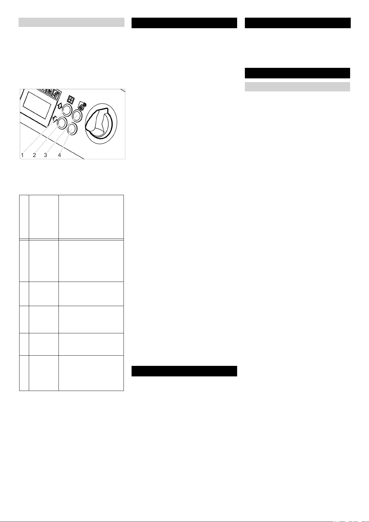
Ajustes básicos
Pulsar simultáneamente las teclas Au-
mentar presión de chorro y Reducir presión de chorro y mantener pulsadas,
girar el interruptor de llave en el sentido
de las agujas del reloj.
En el modo de funcionamiento Ajustes básicos, las teclas tienen las siguientes funciones:
1 Aumentar el valor
2 Reducir el valor
3 Subir punto de menú
4 Bajar punto de menú
Zona de
ajuste
Punto del menú
0, 1, 2, 3,
4, 5 segundos
Arranque suave
1, 2, 3, 4, 5
minutos
T_Dump
metric, imperial
Language
ON/OFF Conectar/desconectar la
Lighting
ON/OFF Modo de demostración:
Demo-Mode
Finalizar las configuraciones básicas
Gire el interruptor de llave en el sentido
opuesto a las agujas del reloj.
Descripción
Arranque suave, duración hasta alcanzar la
presión de chorro seleccionada
Duración del proceso de
vaciado de hielo seco
Unidades de medida
metric: kg/h, MPa
imperial: lbs, psi
iluminación de las boquillas (opcional)
se simula el manejo, la
emisión de aire comprimido y hielo seco están
bloqueadas.
Puesta fuera de servicio
Peligro
Peligro de que se produzcan quemaduras
por frío. El hielo seco tiene una temperatura de -79 °C. No tocar el hielo seco ni las
piezas del aparato frías sin protección. Utilizar guantes de seguridad y ropa protectora.
Peligro
Riesgo de lesiones causadas por pellets de
hielo seco en movimiento. No apuntar a
personas con la pistola de chorreo. Alejar
a terceras personas del lugar de aplicación
y mantenerlas alejadas mientras el aparato
esté en funcionamiento (por ejemplo mediante un bloqueo).
Cerrar el suministro de aire comprimi-
do.
Colocar un recipiente colector bajo la
salida de condensado.
Abrir lentamente la válvula de descarga
de presió y esperar hasta que hayan
salido el condensado y el aire comprimido del aparato.
Colocar un recipiente colector debajo
de la salida de hielo seco.
Pulsar la tecla Vaciado del recipiente
de hielo seco y esperar hasta que el recipiente de hielo seco esté vacío.
El vaciado de hielo seco se para una
vez trascurrido el tiempo configurado
(véase "Configuraciones básicas").
Si es necesario, pulse la tecla Vaciado
del recipiente de hielo seco varias veces.
Nota
Para proteger el medio ambiente, eliminar
el condensado de forma ecológica.
Ponga el interruptor del aparato en "0/
OFF".
Separar el aparato de la tubería de aire
comprimido.
Saque el enchufe de la toma de corrien-
te.
Limpiar y enrrollar el cable de toma a
tierra.
Eliminar los escombros de arenado
conforme a las directrices vigentes.
Transporte
Peligro
Riesgo de accidentes provocados por restos de hielo seco en el seco. Antes de
transportar el aparato en vehículos cerrados se debe eliminar totalmente el hielo
seco para evitar daños personales provocados por el dióxido de carbono.
Antes de transportar el aparato seguir
los pasos indicados en el capítula
"Puesta fuera de sevicio".
Colocar el aparato en el vehículo de
transporte.
Bloquear los frenos de las ruedas gira-
torias.
Fijar el aparato en el vehículo con cintu-
rones.
Almacenamiento
Precaución
¡Peligro de lesiones y daños! Respetar el
peso del aparato en el almacenamiento.
Este aparato sólo se puede almacenar en
interiores.
Mantenimiento y cuidado
Indicaciones de mantenimiento
Para asegurar el funcionamiento correcto
de la instalación deben efectuarse trabajos
de mantenimiento regulares de acuerdo
con el siguiente plan de mantenimiento.
Emplee exclusivamente piezas de repuesto originales del fabricante o piezas recomendadas por él, como
– Piezas de repuesto y piezas de desgaste
– Accesorios
– Combustibles
– Detergentes
Peligro
Riesgo de accidentes al realizar trabajos
en el aparato. Antes de realizar trabajos en
el aparato, seguir los pasos indicados en el
capítulo "Puesta fuera de servicio".
Peligro
Peligro de quemaduras por frío causadas
por el hielo seco o las piezas del aparato
frías. Al trabajar con el aparato, utilizar
ropa protectora contra el frío o eliminar el
hielo seco y dejar calentar el aparato.
Peligro
Peligro por la extensión volumétrica y quemadura por frío.
No llevar nunca el hielo seco a la boca.
Precaución
Peligro de daños en la instalación. No limpiar la pistola pulverizadora con disolvente,
gasolina ni detergentes que contengan
aceite.
Contrato de mantenimiento
Para garantizar el funcionamiento seguro
de la instalación recomendamos firmar un
contrato de mantenimiento. A este respecto póngase en contacto con el Servicio de
atención al cliente de Kärcher.
- 8
71ES
Page 72

Plan de mantenimiento
Trabajos de mantenimiento
Ayuda en caso de avería
Diariamente antes de conectar la instalación
Examinar detenidamente la manguera
del producto abrasivo por si tuviera fisuras, dobleces u otros daños. Las zonas
blandas de la manguera muestran síntomas de desgaste en el interior de la
manguera. Sustituir la manguera defectuosa o gastada por otra nueva.
Comprobar si el cable eléctrico y la cla-
vija están dañados. Solicitar al servicio
técnico que cambie las piezas defectuosas.
Cada 100 horas de servicio
Examinar los acoplamientos de la man-
guera de producto abrasivo, del aparato y de la pistola de chorreo y
comprobar si están dañados o desgastados. El servicio técnico deberá sustituir la manguera y los acoplamientos
del aparato o pistola de chorreo si están
defectuosos.
Examinar el dispositivo de dosificación
y comprobar si está dañado y es estanco. Si se detectan daños/fugas, informar al servicio técnico.
Comprobar la colocación correcta de
las caperuzas de fijación de los neumáticos traseros.
Cada 500 horas o anualmente
Encargar al servicio técnico que exami-
ne el aparato.
Cada 2 años
Renovar la manguera del producto
abrasivo al menos cada 2 años.
Abrir el aparato
Para llevar a cabo ciertos trabajos de mantenimiento se deben retirar los revestimientos laterales del aparato:
Sustituir el inserto de filtro del separador de agua
1 tornillo
2 Parte inferior
3 tuerca
4 Arandela
5 Cartucho filtrante
6 Parte superior
Desatornillar los 4 tornillos.
Extraer la parte inferior.
Desenroscar la tuerca.
Extraer la arandela.
Extraer el cartucho filtrante y sustituirlo
por uno nuevo.
Montar de nuevo el separados de agua
en el orden inverso.
Comprobaciones
Según la BGV D 26, un inspector deberá
realizar las siguientes comprobaciones en
el aparato. Se deben registrar los resultados de la comprobación en un protocolo
escrito. El operador deberá guardar el protocolo de las comprobaciones hasta la siguiente comprobación.
Tras una interrupción en el servicio de
más de un año
Comprobar si la ubicación y el funcio-
namiento son correctos.
Tras cambiar el lugar de instalación
Comprobar si la ubicación, funciona-
miento e instalación son correctos.
Tras realizar trabajos de reparación o
modificaciones que puedan influir en la
seguridad del funcionamiento.
Comprobar si la ubicación, funciona-
miento e instalación son correctos.
Peligro
Riesgo de accidentes al realizar trabajos
en el aparato. Antes de realizar trabajos en
el aparato, seguir los pasos indicados en el
capítulo "Puesta fuera de servicio".
Peligro
Peligro de quemaduras por frío causadas
por el hielo seco o las piezas del aparato
frías. Al trabajar con el aparato, utilizar
ropa protectora contra el frío o eliminar el
hielo seco y dejar calentar el aparato.
Peligro
Peligro por la extensión volumétrica y quemadura por frío.
No llevar nunca el hielo seco a la boca.
1 Cierre de presión
2 Revestimiento lateral
Abrir los cierres de presión en el senti-
do opuesto a las agujas del reloj.
Quite el revestimiento lateral.
72 ES
- 9
Page 73

Averías con indicación en pantalla
Indicación en
pantalla
E001 La tensión de control
E002 El botón de emer-
E003 El aire comprimido KL
E004 La dosificación KL
E005 La pistola de chorro KL
E006 La pistola de chorro KL
E007 El aire comprimido KL
E008 La pistola de chorro
Piloto de control
(KL)
KL se ilumina en rojo.
gencia KL se ilumina
en rojo
se ilumina en rojo.
se ilumina en rojo.
se ilumina en rojo.
se ilumina en rojo.
se ilumina en rojo.
KL se ilumina en naranja.
Posible causa Modo de subsanarla Responsa-
ble
Tensión de control demasiado
baja
Tecla de desconexión de emergencia pulsada.
La presión del suministro de
aire comprimido es demasiado
baja
Avería en la unidad de dosificación
La conexión entre el aparato y la
pistola de chorro está averiada.
Cortocircuito en la pistola de
chorro o el cable de control
Avería en la válvula de regulación de aire comprimido
La palanca de disparo de la pistola de chorro estaba activada
durante la conexión o el desbloqueo del botón de parada de
emergencia.
Apagar la instalación, esperar un poco, encender de
nuevo el aparato.
Comprobar el enchufe.
Si vuelve a aparecer el código de error, diríjase al servicio técnico de Kärcher
El pulsador de parada de emergencia, se desbloquea
girándolo.
Aumentar la presión.
Apagar la instalación, esperar un poco, encender de
nuevo el aparato.
Apagar la instalación, esperar un poco, encender de
nuevo el aparato.
Si vuelve a aparecer el código de error, diríjase al servicio técnico de Kärcher
Comprobar si la conexión de los acopamientos en el
conducto de control es correcta.
Examinar el cable de control por si estuviera dañada.
Sustituir la pistola de chorro o la manguera de chorro
con cable de control.
Consultar al servicio de atención al cliente. Operario
Soltar la palanca de disparo de la pistola de chorreo. Operario
Operario
Operario
Operario
Operario
Operario
Operario
- 10
73ES
Page 74

Averías sin indicación en pantalla
Avería Posible causa Modo de subsanarla Responsa-
ble
No se muestra ninguna
indicación en pantalla
a pesar de que el interruptor principal está
conectado
No hay chorro de aire
comprimido a pesar de
presionar la palanca
de disparo
Chorro de aire comprimido demasiado débil
El chorro de aire comprimido no tiene pellets
de hielo seco
El enchufe no está enchufado en la toma de
corriente.
Se ha activado el fusible F1 Remove side panel, press F1 to reset. Operario
El suministro de aire comprimido tiene demasiada poca presión
Presión de chorro ajustada demasiado baja Aumetar la presión de chorro. Operario
Suministro de tensión interrumpido Comprobar el suministro de tensión. Se debe ilu-
Tecla de desconexión de emergencia pulsada.
El tubo de control no está bien conectado. Comprobar la conexión entre el tubo de control y
El tubo de control está defectuoso Sustituir la manguera de producto abrasivo. Operario
Presión de chorro ajustada demasiado baja Aumetar la presión de chorro. Operario
El suministro de aire comprimido tiene poca
presión o el caudal de compresor es demasiado bajo.
El inserto de filtro del separador de agua está
atascado.
La manguera de producto abrasivo o la pistola de chorreo están atascadas
La dosificación de hielo seco está desconectada (solo la pistola pulverizadora Advanced), la tecla de la dosificación de hielo seco
conexión/desconexión está iluminada en rojo
en la pistola de chorro, en la pantalla aparece
"Ice off".
Recipiente de hielo seco vacío Llenar el recipiente de hielo seco Operario
Hielo seco derretido Vaciar el recipiente de hielo seco y llenar con pe-
El vibrador del recipiente de hielo seco no
funciona
El motor de accionamiento del dispositivo de
dosificación está sobrecargado
Salida de aire comprimido en el recipiente de
hielo seco
El disco de dosificación de la unidad de dosificación está defectuoso
Enchufar la clavija de red a una toma de
corriente.
Comprobar la presión. Operario
minar en verde el piloto de control "Aparato encendido".
El pulsador de parada de emergencia, se desbloquea girándolo. Se debe iluminar en verde el piloto de control "Aparato encendido".
la pistola de chorreo así como entre el tubo de
control y el aparato.
Comprobar la presión y el caudal. Operario
Sustituir el inserto de filtro del separador de agua. Operario
Descongelar la manguera de producto abrasivo y
la pistola de chorreo para solucionar el atasco.
Aumentar la presión y/o reducir la dosis de hielo
seco.
Pulsar la tecla dosificación de hielo seco de la pistola de chorro Advanced.
llets nuevos de hielo seco.
Consultar al servicio de atención al cliente. Operario
Dejar descongelar el dispositivo de dosificación Operario
Limpiar el canal de compensación de presión del
dispositivo de dosificación.
Sustituir el disco de dosificación. Servicio de
Operario
Operario
Operario
Operario
Operario
Operario
Operario
Servicio de
atención al
cliente
atención al
cliente
74 ES
- 11
Page 75

Datos técnicos
Conexión eléctrica
Tensión V 220...240
Tipo de corriente 1~
Frecuencia Hz 50
Potencia conectada kW 0,6
Clase de protección IPX4
interruptor de corriente de defecto delta I in A 0,03
Corriente de fuga, tipo. mA 7,5
aire comprimido
Ancho nominal de la manguera pulgadas 3/4
Presión de suministro (máx.) MPa (bar) 1,6 (16)
Presión de suministro (mín.) MPa (bar) 0,2 (2)
Consumo de aire comprimido m
Calidad de aire comprimido seco, sin aceite
Potencia y rendimiento
Presión de chorro (máx.) MPa (bar) 1,6 (16)
Diámetro de los pellets de hielo seco (máx.) mm 3
Consumo de hielo seco kg/h 30...120
Dimensiones
Contenido recipiente de hielo seco kg 40
Anchura mm 716
Profundidad mm 850
Altura mm 1102
Peso con accesorios kg 101,5
Peso, listo para el funcionamiento, con el recipiente de hielo seco lleno kg 140
Presión de neumático (máx.) MPa (bar) 0,2 (2)
Peso dispositivo de chorro (manguera de producto abrasivo, pistola de chorro, maletín de
herramientas)
Fuerza de retroceso de la pistola de chorreo (máx.) N 100
Par de la pistola de chorro (máx.), sólo para la boquilla acodada N 40
Nivel de presión acústica L
Nivel de potencia acústica L
pA
WA
Inseguridad K dB(A) 5
Vibraciones del aparato
Pistola de chorreo m/s² 1,2
Manguera de producto abrasivo m/s² 1,2
3
/min 2...12
kg 10
dB(A) 114
dB(A) 136
- 12
75ES
Page 76

Accesorios
ropa protectora
Gafas protectoras de visión total, anti-vaho, nº de piezas: 6.321-208.0
Guantes de protección contra el frío con
perfil antideslizante, categoría III conforme
a EN 511, nº de piezas: 6.321-210.0
Protección auditiva con estribo para la cabeza, nº de piezas: 6.321-207.0
Dispositivo de chorro
Boquilla de chorro rendondo, L, larga
Nº de pieza: 4.574-019.0
Boquilla de chorro rendondo, L, extra larga
Nº de pieza: 4.574-016.0
boquilla de chorro redondo, M, larga
Nº de pieza: 4.574-018.0
boquilla de chorro redondo, M, corta
Nº de pieza: 4.130-418.0
boquilla de chorro redondo, L, corta
Nº de pieza: 4.130-419.0
Boquilla de chorro plano
Nº de pieza: 4.130-423.0
Juego de boquillas de chorro plano, M, 6
mm
Nº de pieza: 4.130-421.0
Juego de boquillas de chorro plano, L,
8mm
Nº de pieza: 4.130-420.0
Juego de boquillas de chorro plano, _XL,
10 mm
Nº de pieza: 4.130-422.0
Lanza de agua angular 90º
Nº de pieza: 4.321-203.0
Lanza de agua angular 105º
Nº de pieza: 4.321-204.0
Prolongación de la boquilla, 300 mm de largo
Nº de pieza: 4.130-417.0
Mango
Nº de pieza: 6.321-206.0
Garantía
En todos los países rigen las condiciones
de garantía establecidas por nuestra empresa distribuidora. Las averías del aparato
serán subsanadas gratuitamente dentro
del periodo de garantía, siempre que se
deban a defectos de material o de fabricación. En un caso de garantía, le rogamos
que se dirija con el comprobante de compra al distribuidor donde adquirió el aparato
o al servicio al cliente autorizado más
próximo a su domicilio.
Declaración de conformidad
CE
Por la presente declaramos que la máquina designada a continuación cumple, tanto
en lo que respecta a su diseño y tipo constructivo como a la versión puesta a la venta
por nosotros, las normas básicas de seguridad y sobre la salud que figuran en las directivas comunitarias correspondientes. La
presente declaración perderá su validez en
caso de que se realicen modificaciones en
la máquina sin nuestro consentimiento explícito.
Producto: Dispositivo de chorro de hie-
Modelo: 1.574-xxx
Directivas comunitarias aplicables
2006/42/CE (+2009/127/CE)
2004/108/CE
Normas armonizadas aplicadas
EN 55014–1: 2006+A1: 2009+A2: 2011
EN 55014–2: 1997+A1: 2001+A2: 2008
EN 60204–1
EN 61000–3–2: 2006+A1: 2009+A2: 2009
EN 61000–3–3: 2008
EN 62233: 2008
Normas nacionales aplicadas
GS-STE-13 (conforme)
Los abajo firmantes actúan con plenos poderes y con la debida autorización de la dirección de la empresa.
CEO
Persona autorizada para la documentación:
S. Reiser
rro seco
Head of Approbation
Scrambler
Nº. de pieza: 4.110-015.0
Iluminación de trabajo
Nº de pieza: 2.815-422.0
Manguera protectora para la lanza dosificadora, plástico, 100 m
Nº de pieza: 6.667-214.0
Alfred Kärcher GmbH & Co. KG
Alfred-Kärcher-Str. 28 - 40
71364 Winnenden (Germany)
Tele.: +49 7195 14-0
Fax: +49 7195 14-2212
Winnenden, 2013/02/01
76 ES
- 13
Page 77

Leia o manual de manual origi-
nal antes de utilizar o seu aparelho. Proceda conforme as indicações no
manual e guarde o manual para uma consulta posterior ou para terceiros a quem
possa vir a vender o aparelho.
Índice
Protecção do meio ambiente PT . . 1
Avisos de segurança . . . . . PT . . 1
Utilização conforme o fim a que
se destina a máquina . . . . . PT . . 2
Funcionamento . . . . . . . . . . PT . . 2
Elementos de manuseamento PT . . 3
Colocação em funcionamento PT . . 4
Manuseamento . . . . . . . . . . PT . . 6
Colocar fora de serviço. . . . PT . . 8
Transporte. . . . . . . . . . . . . . PT . . 8
Armazenamento . . . . . . . . . PT . . 8
Manutenção e conservação PT . . 8
Ajuda em caso de avarias . PT . . 9
Dados técnicos . . . . . . . . . . PT . 12
Acessórios . . . . . . . . . . . . . PT . 13
Garantia . . . . . . . . . . . . . . . PT . 13
Declaração de conformidade
CE. . . . . . . . . . . . . . . . . . . . PT . 13
Protecção do meio ambiente
Os materiais de embalagem são recicláveis. Não coloque as embalagens
no lixo doméstico, envie-as para uma
unidade de reciclagem.
Os aparelhos velhos contêm materiais preciosos e recicláveis e deverão ser reutilizados. Baterias, óleo e
produtos similares não podem ser
deitados fora ao meio ambiente. Por
isso, elimine os aparelhos velhos
através de sistemas de recolha de
lixo adequados.
Avisos sobre os ingredientes (REACH)
Informações actuais sobre os ingredientes
podem ser encontradas em:
www.kaercher.com/REACH
Avisos de segurança
O aparelho só pode ser operado por pessoas que tenham lido e compreendido o
manual de instruções. Deve ser dada especial atenção a todas as indicações de
segurança.
Este manual de instruções deve ser
guardado num local de fácil e livre
acesso.
Níveis de perigo
Perigo
Para um perigo eminente que pode conduzir a graves ferimentos ou à morte.
몇 Advertência
Para uma possível situação perigosa que
pode conduzir a graves ferimentos ou à
morte.
Atenção
Para uma possível situação perigosa que
pode conduzir a ferimentos leves ou danos
materiais.
Símbolos no aparelho
Perigo
Perigo de ferimentos por bolas de gelo
seco projectadas. Não apontar a pistola de
jacto contra pessoas. Afastar terceiros do
local de aplicação e mantê-los afastados
durante os trabalhos (p. ex. com uma vedação).
Durante a operação não se deve aceder
com a mão ao bocal nem ao jacto de gelo
seco.
Perigo
Perigo de asfixia por dióxido de carbono.
As bolas de gelo seco são compostas por
dióxido de carbono. Durante a operação do
aparelho, o teor de dióxido de carbono no
ar sobe do local de trabalho. Arejar suficientemente o local de trabalho e utilizar
eventualmente um aparelho de advertência: Indícios de elevado teor de dióxido de
carbono no ar de respiração:
– 3...5%: dores de cabeça, elevada fre-
quência de respiração.
– 7...10%: dores de cabeça, má disposi-
ção e event. perda de consciência.
Desligar imediatamente o aparelho se alguns destes indícios surgir e deslocar-se
para o ar livre. Melhorar as medidas de
ventilação antes de continuar os trabalhos
ou utilizar um aparelho de respiração.
Observar a ficha técnica de segurança do
fabricante do ar seco.
Perigo
Perigo de ferimentos motivados por descargas electrostáticas, perigo de danos
dos módulos electrónicos. Durante o processo de limpeza, o objecto sujeito à limpeza pode sofrer um carregamento eléctrico.
Assim sendo, o objecto sujeito à limpeza
deve ser ligado à terra e essa mesma ligação deve ser mantida durante todo o processo de limpeza.
Perigo
Perigo de ferimentos por choque eléctrico.
Retire a ficha da tomada antes de proceder
à abertura do armário de comando.
Perigo
Perigo de queimaduras do gelo. Gelo seco
tem uma temperatura de -79 °C. Nunca toque no gelo seco ou em peças da máquina
frias sem qualquer protecção.
Perigo
Perigo de ferimentos por bolas de gelo
seco projectadas ou partículas de sujidade.
Utilizar um óculo de protecção bem vedado.
Perigo de danos no aparelho auditivo. Utilizar dispositivo de protecção auditiva.
O equipamento de protecção não pode interferir no contacto visual e na comunicação no local de trabalho.
Perigo
Perigo de ferimentos por pellets de gelo
seco projectados ou partículas de sujidade.
Perigo de ferimentos devido ao contacto
com componentes do aparelho frios.
Usar luvas de protecção segundo a norma
EN 511 e vestuário de protecção que cubra
os braços.
Indicações gerais de segurança
Perigo
Perigo de ferimentos motivado pela activação inadvertida do aparelho. Retirar a ficha
da tomada antes de iniciar os trabalhos
com o aparelho.
Perigo
Perigo de ferimentos por choque eléctrico.
Retire a ficha da tomada antes de proceder
à abertura do armário de comando.
Perigo
Perigo de queimaduras provocadas por
gelo seco ou peças frias do aparelho. Usar
roupa adequada durante os trabalhos com
o aparelho ou remover o gelo seco e permitir o aquecimento do aparelho.
Perigo
Perigo devido à dilatação volumétrica e
queimadura de frio.
Nunca colocar gelo seco na boca.
- 1
77PT
Page 78

몇
Advertência
Perigo de acidente devido à força de recuo
da pistola de jacto. Antes de accionar o gatilho de disparo da pistola de jacto, deve-se
procurar uma posição segura e segurar firmemente a pistola de jacto.
Perigo
Perigo de ferimentos por objectos projectados. Fixar eventuais objectos de pequenas
dimensões/leves sujeitos a limpeza, de
modo a evitar que sejam projectados pelo
jacto de gelo seco.
몇 Advertência
Perigo de esmagamento no dispositivo de
dosagem. Antes de proceder à remoção da
chapa de protecção no recipiente de gelo
seco é de extrema importância retirar a ficha de rede do aparelho da respectiva tomada.
Normas e directivas
Na República Federal da Alemanha são
aplicáveis as seguintes prescrições e normas para a operação desta instalação (a
solicitar na Carl Heymanns Verlag KG, Luxemburger Straße 449, 50939 Köln):
– BGV D 26 Trabalhos com jactos
– Instrução de execução referente a
BGV D 26
– BGR 117 Trabalhar em espaços reduzi-
dos
– BGR 139 Regras de segurança para
pessoas - Sistemas de sinalização de
emergência.
– BGR 189 Aplicação de vestuário de
protecção
– BGR 195 Aplicação de luvas de protec-
ção
– BGR 500 Operação de ferramentas de
trabalho
– BGI 534 Trabalhar em espaços reduzi-
dos
– BGI 836 Dispositivo de advertência de
gás
Ter atenção às prescrições nacionais de
segurança e aos regulamentos das associações profissionais!
Equipamento de segurança
Utilização conforme o fim a
que se destina a máquina
O aparelho serve para a remoção de sujidade com bolas de gelo seco que são projectadas com um jacto de ar.
O aparelho não pode ser operado num ambiente potencialmente explosivo.
Como meio projectado no jacto só podem
ser utilizadas bolas de gelo seco. A utilização de outros meios projectados pode resultar na danificação do aparelho.
Funcionamento
Ar comprimido é encaminhado por uma
válvula de regulação da pressão para a
pistola de jacto. Para o accionamento do
gatilho de disparo da pistola de jacto, a válvula abre-se e o jacto de ar sai da pistola
de jacto. Adicionalmente são adicionadas
bolas de gelo seco ao jacto de ar, através
do dispositivo de dosagem. A dosagem
pode ser desligada com o interruptor selector do modo de operação. As bolas de gelo
frio embatem na superfície que pretende
limpar e removem a sujidade. As bolas de
gelo frio de -79 °C provocam tensões térmicas adicionais entre a sujidade e o objecto de limpeza, as quais contribuem
adicionalmente para a dissolução da sujidade. Além disso, o gelo que embate no
objecto transforma-se imediatamente em
dióxido de carbono e afecta, desse modo,
700 vezes o volume normal. O gelo seco
posiciona-se entre o objecto e a sujidade,
removendo a mesma.
Durante a operação a jacto, um vibrador no
recipiente do gelo frio assegura a alimentação contínua de bolas de gelo frio.
Botão de paragem de emergência
Se premir o botão de Desactivação de
Emergência, a dosagem do gelo seco pára
e a corrente de ar do bico é interrompida.
Desactivação em caso de
emergência
Soltar o gatilho de disparo da pistola de
jacto.
Premir o botão de paragem de emer-
gência.
A dosagem do gelo seco é parada e a corrente de ar do bocal interrompida.
Interromper a alimentação do ar com-
primido.
78 PT
- 2
Page 79

Elementos de manuseamento
Aparelho
1 Fusível F1, por baixo da carenagem la-
teral
2 Ligação do ar comprimido
3 Evacuação de condensado
4 Alavanca de avanço
5 Fecho, mala
6 Suporte para a pistola de jacto
7 Mala para acessórios
8 Destravamento, fixação da mala
9 Pega de transporte, mala
10 Braçadeira para cabo
11 Válvula de descarga da pressão, sepa-
rador de água do esvaziamento do con-
densado
12 Pega de transporte, arco de protecção
na traseira
13 Cabo de rede com ficha
14 Saída do gelo seco, para o esvazia-
mento do recipiente
15 Rolo de guia com travão de imobiliza-
ção
16 Acoplamento da mangueira do produto
projectado
17 Cabo de ligação à terra com terminal
18 Acolpamento do cabo de comando
19 Painel de comando
20 Prateleira para acessórios
21 Tampa do recipiente do gelo seco
Painel de comando Display
1 Tecla "Estatística", repor contador
2 Tecla "Aumentar a pressão do jacto"
3 Tecla "Aumentar a dosagem do gelo
seco"
4 Interruptor da máquina
5 Botão de paragem de emergência
6 Interruptor de chave
7 Tecla "Reduzir a dosagem do gelo se-
co"
8 Tecla "Reduzir a pressão do jacto"
9 Display
10 Tecla "Esvaziamento do recipiente do
gelo seco"
1 Lâmpada de controlo da tensão de co-
mando
verde: tensão de comando OK
vermelho: Tensão de comando baixa
amarelo: esvaziamento do recipiente
do gelo seco activo
2 Lâmpada de controlo da Desactivação
de Emergência
vermelho: botão de Desactivação de
Emergência accionado
verde: botão de Desactivação de Emer-
gência não accionado
3 Lâmpada de controlo do ar comprimido
verde: pressão OK
cor-de-laranja: pressão seleccionada
não atingida
vermelho: pressão baixa (inferior a 0,15
MPa/1,5 bar)
- 3
79PT
Page 80

4 Lâmpada de controlo do dispositivo de
dosagem
verde: accionamento OK
vermelho: avaria no accionamento
5 Lâmpada de controlo da pistola de jacto
verde: pistola de jacto OK
cor-de-laranja: gatilho da pistola de jac-
to, premido durante a activação
vermelho: pistola de jacto desencaixa-
da ou cabo de comando danificado
6 Campo de indicação
Dispositivo do jacto
Pistola de jacto
1 Bocal
2 Pistola de jacto
3 Acoplamento da mangueira do produto
projectado
4 Acolpamento do cabo de comando
5 Alavanca de segurança
6 Gatilho de disparo
7 Interruptor do modo de operação
Posição ”1”: jacto de ar comprimido
Posição ”2”: jacto de gelo seco (ar com-
primido e bolas de gelo seco)
Posto de jacto Advanced (opção)
9 Tecla "Aumentar a pressão do jacto"
10 Tecla "Reduzir a pressão do jacto"
11 Tecla "Reduzir a dosagem do gelo se-
co"
Mala para acessórios
A mala destina-se ao armazenamento dos
bicos e das respectivas ferramentas.
1 Fecho
2 Pega para portar
3 Dispositivo de destravamento
Abrir mala
Abrir fechos.
Girar a tampa para baixo.
Atenção
Perigo de danos, não posicionar objectos
pesados em cima da tampa aberta.
Separar a mala do aparelho.
Premir o destravamento e retirar a ma-
la.
Montar a mala no aparelho.
Rodar a mala com os fechos para cima.
Posicionar uma parte da mala no su-
porte e engatar.
Pressionar a mala contra o aparelho e
engatar o encaixe do lado oposto.
Bocais
Aviso
A selecção do bocal depende do material
do qual é composto o objecto sujeito a lavagem e do grau de sujidade.
Além disso, o volume de ar disponível tem
uma influência fundamental sobre a escolha do pulverizador.
Todos os bocais são enroscados sem ferramentas na rosca da pistola de jacto. As
superfícies de chave situadas no bocal servem para desaparafusar bocais que estejam presos e que possam ser retirados
com uma chave de bocas.
Atenção
Perigo de fusão a frio. Aplicar uma camada
de massa consistente na rosca do bocal
antes da respectiva montagem.
Selecção do bocal
A tabela seguinte mostra o consumo de ar
com diferentes pulverizadores.
Cada pulverizador está assinalado com um
índice do volume de ar XS - XXL.
Com a tabela dos pulverizadores é portanto possível determinar para cada pulverizador o consumo de ar.
1 Bocal
2 Pistola de jacto
3 Gatilho de disparo
4 Botão de segurança
5 Acoplamento da mangueira do produto
projectado
6 Acolpamento do cabo de comando
7 Tecla "Dosagem do gelo seco Lig/Desl"
Brilha vermelho com a dosagem do
gelo seco desactivada
8 Tecla "Aumentar a dosagem do gelo
seco"
Colocação em
funcionamento
Perigo
Perigo de ferimentos por bolas de gelo
seco projectadas.
Antes de iniciar os trabalhos deve-se controlar todos os módulos do aparelho, dando
especial atenção à mangueira do produto
projectado. Substituir os módulos danificados por novos.
Limpar os módulos sujos e verificar o funcionamento correcto dos mesmos.
Posicionar o aparelho numa superfície
horizontal e plana e bloquear o travão
de imobilização dos rolos de guia.
Aviso:
Para proteger a mangueira contra desgaste e sujidade é possível revesti-la com uma
mangueira de protecção. Se necessário,
posicionar a mangueira de protecção sobre
a mangueira do jacto, antes de a conectar.
Unir a mangueira do produto projecta-
do ao aparelho e fixar.
Unir a pistola de jacto à mangueira do
produto projectado e fixar.
Unir o cabo de comando com o apare-
lho.
Unir o cabo de comando com a pistola
de jacto.
80 PT
- 4
Page 81

Agressividade do
Muito baixa Baixa Média Alto Muito alta
jacto
Pressão (bar) 2 3 4 5 6 7 8 9 10 11 12 13 14 15 16
Tamanho do bo-
cal
Área abrangida
XS Ø5 mm 0,40 0,70 0,90
S Ø6 mm 0,70
M Ø7 mm 0,93
L Ø8 mm
XL Ø9 mm
XXL Ø10 mm
1,05 1,45 1,80 2,07 2,40 2,78 3,14 3,48 3,78 4,13 4,35 4,70 5,10 5,40
1,38 1,85 2,28 2,64 3,05 3,63 4,03 4,57 4,80 5,30 5,80 6,22 6,65 7,15
1,09 1,64 2,26 2,78 3,20 3,79 4,40 4,95 5,45 5,90 6,40 7,15 7,67 8,15 8,80
1,50 2,16 2,88 3,50 4,03 4,60 5,41 6,01 6,53 7,27 8,08 8,70 9,28 9,80 10,40
1,52 2,20 2,97 3,66 4,27 5,00 5,82 6,52 7,40 8,00 8,90 9,50 10,05 10,70 11,30
Consumo de ar em m
1,10 1,30 1,60 1,80 2,00 2,30 -- -- -- -- -- --
3
/min
m3/min
...1 Rede interna de ar com-
primido industrial
Compressor base
p. ex. Käser M 17,
Compair C 14
1...2 Rede interna de ar comprimido industrial
Compressor pequeno
p. ex. Käser M 31,
Compair C 20GS
2...3 Compressor médio
3...5
p. ex. Käser M 57,
Compair C 35
5...7 Compressor médio
p. ex. Käser M 80,
Compair C 55
7...10 Compressor grande
p. ex. Käser M 122,
Compair C 105
10... Compressor muito grande
p. ex. Käser M 250,
Compair C 200
Bocal de jacto redondo
Além do bocal de jacto redondo incluído no
volume de fornecimento, existem ainda outros bocais de jacto redondo com cortes
transversais distintos na qualidade de
acessórios.
Bocal de fenda (jacto plano)
1 Difusor
2 Porca de capa
3 Encaixe do bocal
O bocal de fenda é composto pelo encaixe
do bocal e o difusor. Na qualidade de acessórios são disponibilizados encaixes de bocais com vários cortes transversais.
Colocar o encaixe do bocal na rosca da
pistola de jacto e apertar com a mão.
Posicionar o difusor no bocal.
Rodar o difusor de modo que o jacto
plano tenha a posição pretendida em
relação à pistola de jacto.
Apertar a porca de capa manualmente.
Scrambler (acessório)
O Scrambler reduz o tamanho das bolas de
gelo seco e é montado entre a pistola de
jacto e o bocal.
O alinhamento das 4 placas perfuradas no
Scrambler predefine o grau da redução do
tamanho.
Escolher o grau da redução do tamanho:
1 União roscada
2 Carregador
3 Placa perfurada
Desaparafusar a união roscada.
Retirar o carregador com as placas per-
furadas.
1 Bocal de jacto redondo, curto
2 Bocal de jacto redondo, comprido
3 Bocal de jacto redondo, extra comprido
Colocar o bocal de jacto redondo na
rosca da pistola de jacto e apertar com
a mão.
- 5
Alinhar as placas perfuradas, conforme
suprailustrado, no carregador (3 possibilidades). A indicação cotada na figura
é referente ao tamanho das aberturas
de passagem.
Inserir o carregador com as placas per-
furadas no Scrambler.
Aparafusar e apertar a união roscada.
81PT
Page 82

Alongamento do bocal (acessório)
Entre a pistola de jacto e o bocal pode ser
montado um alongamento.
Tubo de jacto angular (acessório)
O tubo de jacto angular é posicionado entre a pistola de jacto e o pulverizador.
1 Tubo de jacto angular 105°
2 Tubo de jacto angular 90°
몇 Advertência
Perigo de ferimentos. Durante a utilização
do tubo de jacto angular, sobre a pistola
pulverizadora incide uma força de recuo e
um binário. Segurar fortemente a pistola
pulverizadora.
Iniciar os trabalhos com baixa pressão de
jacto e eventualmente aumentar a pressão
do jacto.
Punho (acessório)
A pega pode ser fixada na extensão.
Iluminação de trabalho (acessório)
(apenas na pistola de jacto Advanced)
A iluminação de trabalho é posicionada entre a pistola de jacto e o bocal. A activação
e desactivação é descrita no capítulo "Manuseamento/Ajustes base".
Ligar o ar comprimido
Aviso
Para assegurar o bom funcionamento sem
avarias, é necessário que o ar comprimido
tenha um baixo teor de humidade. O ar
comprimido deve estar livre de óleo, sujidade e corpos estranhos.
O compressor deve estar, pelo menos,
equipado com refrigerador, separador de
óleo e água.
Fechar a válvula de descarga da pres-
são.
Ligar a linha adutora do ar comprimido
à ligação de ar comprimido do aparelho.
A pressão de alimentação máx. admissível de 1,6MPa (16 bar) não pode ser
excedida.
Estabelecer a ligação à rede
Perigo
Perigo devido a choque eléctrico.
A tomada utilizada tem que ser instalada
por um electricista credenciado e tem que
corresponder a IEC 60364-1.
O aparelho deve ser devidamente protegido por um disjuntor FI do tipo B, 30 mA.
Controlar o cabo de ligação de rede do
aparelho quanto a eventuais danos, antes
de cada operação. Não colocar o aparelho
em funcionamento se o cabo do mesmo
estiver danificado. Requerer a substituição
do cabo danificado por um electricista.
O cabo de extensão deve garantir uma protecção IPX4 e a versão do cabo deve corresponder pelo menos a H 07 RN-F 3G1,5.
Ligue a ficha de rede à tomada de cor-
rente.
Manuseamento
Encher gelo seco
Perigo
Perigo de queimaduras do gelo. Gelo seco
tem uma temperatura de -79 °C. Nunca toque no gelo seco ou em peças da máquina
frias sem qualquer protecção. Usar luvas e
roupa de protecção.
Abrir a tampa do recipiente do gelo se-
co.
Controlar o recipiente do gelo seco re-
lativamente a corpos estranhos e condensado e remover.
Encher bolas de gelo seco no recipien-
te.
Atenção
Perigo de danificação do aparelho. Como
meio projectado no jacto só podem ser utilizadas bolas de gelo seco. A utilização de
outros meios de jacto resulta na anulação
dos direitos de garantia.
Fechar a tampa do recipiente do gelo
seco.
Aviso
De modo a evitar danos provocados por
bolas de gelo seco aglomeradas é recomendado que todo o conteúdo do recipiente do gelo seco seja consumido, antes de
inserir mais gelo seco. Antes de longas interrupções de funcionamento, deve-se
operar o aparelho até o recipiente das bolas de gelo seco ficar vazio ou esvaziar o
recipiente através da função de esvaziamento do gelo seco.
Ajustes
Aviso
Os ajustes dependem do material do qual
é composto o objecto sujeito a lavagem e
do grau de sujidade.
Destravar o botão de parada de emer-
gência, rodando-o.
Colocar o selector na posição "I".
Rodar o interruptor de chave no sentido
dos ponteiros do relógio.
Ajustar a pressão do jacto com as te-
clas "Aumentar/reduzir pressão do jacto".
Aviso
Quanto maior for a pressão ajustada do
jacto, maior (mais agressivo) será o efeito
de limpeza.
Ajustar a dosagem do gelo seco com as
teclas "Aumentar/reduzir a dosagem do
gelo seco".
Rodar o interruptor chave no sentido
oposto ao dos ponteiros do relógio e retirar a chave.
Através do fecho automático da fechadura é evitada a contaminação durante
o funcionamento.
Com a chave retirada, o aparelho está
protegido contra a alteração do ajuste e
a reposição dos valores estatísticos.
Funcionamento
Realizar os trabalhos de manutenção
"diariamente antes da operação do
aparelho" (ver a secção "Manutenção e
conservação“).
Perigo
Perigo de ferimentos por bolas de gelo
seco projectadas. Não apontar a pistola de
jacto contra pessoas. Afastar terceiros do
local de aplicação e mantê-los afastados
durante os trabalhos (p. ex. com uma vedação).
Durante a operação não se deve aceder
com a mão à abertura do bocal nem ao jacto de gelo seco.
Antes de proceder à separação da ligação
entre a pistola de jacto e a mangueira do
meio projectado e entre a mangueira do
meio projectado e o aparelho é obrigatório
interromper a alimentação do ar comprimido, tornar o aparelho isento de tensão e retirar a ficha da tomada.
Vedar a zona dos trabalhos de modo a
evitar o acesso de pessoas durante os
trabalhos.
82 PT
- 6
Page 83

Perigo
Perigo de asfixia por dióxido de carbono.
As bolas de gelo seco são compostas por
dióxido de carbono. Durante a operação do
aparelho, o teor de dióxido de carbono no
ar sobe do local de trabalho. Ventilar o espaço de trabalho e utilizar eventualmente
um aparelho de aviso de pessoas ou aparelhos de protecção respiratória.
Indícios de elevada concentração de dióxido de carbono no respiratório:
– 3...5%: dores de cabeça, elevada fre-
quência de respiração.
– 7...10%: dores de cabeça, má disposi-
ção e event. perda de consciência.
Desligar imediatamente o aparelho se alguns destes indícios surgir e deslocar-se
para o ar livre. Melhorar as medidas de
ventilação antes de continuar os trabalhos
ou utilizar um aparelho de respiração.
O dióxido de carbono acumula em locais
profundos. Prevenir a acumulação através
da ventilação.
Observar a ficha técnica de segurança do
fabricante do ar seco.
Perigo
Perigo por substâncias nocivas à saúde.
Se durante os trabalhos for possível a formação de pós nocivos, deve-se tomar as
devidas precauções antes de iniciar os trabalhos.
Perigo
Perigo de explosão!
Não trabalhar simultaneamente metais leves e metais ferrosos.
Se trabalhar alternadamente metais leves
e metais ferrosos, é necessário limpar a
sala de trabalho e a unidade de aspiração
antes de mudar de um tipo de metal para o
outro.
Perigo devido à explosão de pó. Se durante os trabalhos forem produzidos pós inflamáveis, deve-se evitar a acumulação de
pó. Remover o pó regularmente antes da
acumulação de quantidades críticas.
Durante os trabalhos em espaço aper-
tados deve ser assegurada uma ventilação suficiente do ar, de modo a
manter a concentração de dióxido de
carbono abaixo dos níveis perigosos.
Fixar eventualmente o objecto de lim-
peza.
Perigo
Perigo de ferimentos motivados por descargas electrostáticas, perigo de danos
dos módulos electrónicos. Durante o processo de limpeza, o objecto sujeito à limpeza pode sofrer um carregamento eléctrico.
Assim sendo, o objecto sujeito à limpeza
deve ser ligado à terra e essa mesma ligação deve ser mantida durante todo o processo de limpeza.
몇 Advertência
Perigo de lesões provocadas por tropeçar.
Instalar a mangueira do produto de jacto e
o cabo de comando de modo a evitar perigos de tropeçamento.
Atenção
Perigo de danos devido a corpos estranhos
que caiam para dentro do recipiente do
gelo seco. Manter a tampa do recipiente do
gelo seco fechada durante o funcionamento do aparelho.
Unir o fio terra ao objecto de limpeza ou
efectuar a ligação terra de outra forma.
Usar roupa de protecção, luvas de pro-
tecção, óculo de protecção bem vedados e protecção auditiva.
Activar a alimentação do ar comprimi-
do.
Destravar o botão de parada de emer-
gência, rodando-o.
Regular o modo operativo de jacto de
ar comprimido "1" ou jacto de gelo seco
"2" no botão selector dos modos operativos da pistola de jacto.
Seleccionar um local de posicionamen-
to seguro para o aparelho e tomar uma
postura segura, para não perder a estabilidade com a carga de recuo da pistola de jacto.
De modo a impedir uma força de recuo
(coice) repentina, é possível ajustar um
aumento lento e gradual da pressão do
jacto (ver "Manuseamento/Ajustes base“ ponto de menu "Arranque suave").
Premir o botão de segurança da pistola
de jacto.
Activar o jacto do gelo seco com o gati-
lho de disparo para realizar o processo
de limpeza.
Aviso
No caso de utilização da pistola de jacto
Advanced é possível ligar e desligar a dosagem das bolas de gelo seco com a tecla
"Dosagem de gelo seco Desl/Lig" na pistola de jacto. Com a dosagem desligada, a
tecla brilha a vermelho e no display é indicado "Ice off".
Adicionalmente, a pistola de jacto Advanced permite regular a pressão do jacto e a
quantidade de gelo seco.
Atenção
Perigo de danificação do dispositivo de dosagem devido a sujidade. Manter a tampa
do recipiente do gelo seco fechada durante
o funcionamento, de modo a evitar a entrada de sujidade solvida.
Desactivação em caso de
emergência
Soltar o gatilho de disparo da pistola de
jacto.
Premir o botão de paragem de emer-
gência.
A dosagem do gelo seco é parada e a corrente de ar do bocal interrompida.
Interromper a alimentação do ar com-
primido.
Colocação em funcionamento após
a desactivação de emergência
Destravar o botão de parada de emer-
gência, rodando-o.
Interromper o funcionamento
Soltar o gatilho de disparo da pistola de
jacto.
Durante os intervalos e pausas a pisto-
la de jacto pode ser encaixada no suporte do aparelho.
Aviso
Durante interrupções ou intervalos prolongados, as bolas de gelo seco podem fundir-se no recipiente do gelo seco. Os
trabalhos não devem ser interrompidos durante períodos superiores a 20 minutos.
Esvaziar o recipiente do gelo seco, sempre
que forem previstas interrupções longas.
Evacuar o condensado
Um separador de água purifica o ar comprimido fornecido ao aparelho. Deste forma
acumula-se condensado no separador de
água, que tem que ser esvaziado de tempos em tempos.
Colocar o recipiente de captura por bai-
xo da descarga do condensado.
Abrir lentamente a válvula de descarga
da pressão e aguardar até o condensado sair do aparelho.
Aviso
Eliminar o condensado em conformidade
com o meio-ambiente, a fim de proteger o
meio-ambiente.
Função de estatística
Consultar os valores
Colocar o selector na posição "I".
Premir brevemente a tecla da estatísti-
ca: o tempo de operação é indicado.
t: tempo de operação desde a última re-
posição.
T: tempo total de operação.
Premir brevemente a tecla da estatísti-
ca; a quantidade de gelo seco produzido é indicada.
m: quantidade de gelo seco desde a última reposição.
M: total de gelo seco.
Premir brevemente a tecla da estatísti-
ca; o consumo médio de gelo seco é indicado.
q: consumo médio de gelo seco, desde
a última reposição.
Q: consumo médio total de gelo seco.
Repor os valores
Rodar o interruptor de chave no sentido
dos ponteiros do relógio.
Premir a tecla estatística durante 4 se-
gundos.
Aviso
Os valores totais não podem ser apagados.
- 7
83PT
Page 84

Ajustes base
Premir simultaneamente a tecla de au-
mento e redução da pressão do jacto e
rodar ao mesmo tempo o interruptor de
chave no sentido dos ponteiros do relógio.
No modo operativo dos ajustes base, as teclas têm as seguintes funções:
1 Aumentar valor
2 Reduzir valor
3 Ponto de menu para cima
4 Ponto de menu para baixo
Gama de
ajuste
Ponto do menu
0, 1, 2, 3,
4, 5 segundos
Arranque suave
1, 2, 3, 4, 5
minutos
T_Dump
metric, imperial
Language
ON/OFF Ligar/desligar a ilumina-
Lighting
ON/OFF Operação de demonstra-
Demo-Mode
Terminar os ajustes base
Rodar o interruptor de chave no sentido
oposto ao dos ponteiros do relógio.
Descrição
Arranque suave, tempo
até ser atingida a pressão do jacto ajustada
Duração do processo de
esvaziamento de gelo
seco
Unidades de medida
metric: kg/h, MPa
imperial: lbs, psi
ção do bocal (opção)
ção: manuseamento é simulado, as saídas do ar
comprimido e do gelo
seco estão bloqueadas.
Colocar fora de serviço
Perigo
Perigo de queimaduras do gelo. Gelo seco
tem uma temperatura de -79 °C. Nunca toque no gelo seco ou em peças da máquina
frias sem qualquer protecção. Usar luvas e
roupa de protecção.
Perigo
Perigo de ferimentos por bolas de gelo
seco projectadas. Não apontar a pistola de
jacto contra pessoas. Afastar terceiros do
local de aplicação e mantê-los afastados
durante os trabalhos (p. ex. com uma vedação).
Fechar a alimentação do ar comprimi-
do.
Colocar o recipiente de captura por bai-
xo da descarga do condensado.
Abrir lentamente a válvula de descarga
da pressão e aguardar até o condensado e o ar comprimido sairem do aparelho.
Posicionar o recipiente de recolha por
baixo da saída do gelo seco.
Premir a tecla do esvaziamento do reci-
piente do gelo seco e aguardar até o recipiente do gelo seco ficar vazio.
O esvaziamento do gelo seco pára
após expiração do tempo predefinido
(ver "Ajustes base").
Em caso de necessidade deve premir
várias vezes a tecla para o esvaziamento do recipiente do gelo seco.
Aviso
Eliminar o condensado em conformidade
com o meio-ambiente, a fim de proteger o
meio-ambiente.
Colocar o interruptor do aparelho na
posição "0/OFF".
Separar o aparelho da linha adutora do
ar comprimido.
Puxar a ficha de rede da tomada.
Limpar e enrolar o cabo de ligação à
terra.
Eliminar o material de granalhagem
conforme as prescrições em vigor.
Transporte
Perigo
Perigo de acidentes devido a restos de
gelo seco no aparelho. Antes de proceder
ao transporte do aparelho em viaturas fechadas é necessário remover todo o gelo
seco do aparelho, de modo a evitar os riscos provocados pelo dióxido de carbono
sobre as pessoas na viatura.
Proceda à leitura do capítulo "Coloca-
ção fora de serviço" antes de realizar o
transporte do aparelho.
Colocar o aparelho na viatura de trans-
porte.
Travar os travões dos rolos de guia.
Fixar o aparelho com cintas e correias
na viatura.
Armazenamento
Atenção
Perigo de ferimentos e de danos! Ter atenção ao peso do aparelho durante o armazenamento.
Este aparelho só pode ser armazenado em
espaços fechados e cobertos.
Manutenção e conservação
Indicações de manutenção
Para uma instalação segura é imprescindível a manutenção regular de acordo com o
seguinte plano de manutenção.
Utilize unicamente peças originais do produtor ou peças recomendadas pelo mesmo, como
– Peças de reposição e de desgaste,
– Acessórios,
– Produtos de consumo,
– Detergentes.
Perigo!
Perigo de acidentes durante os trabalhos
no aparelho. Antes de iniciar os trabalhos
no aparelho devem ser realizados todos os
passos descritos no capítulo "Colocação
fora de serviço".
Perigo
Perigo de queimaduras provocadas por
gelo seco ou peças frias do aparelho. Usar
roupa adequada durante os trabalhos com
o aparelho ou remover o gelo seco e permitir o aquecimento do aparelho.
Perigo
Perigo devido à dilatação volumétrica e
queimadura de frio.
Nunca colocar gelo seco na boca.
Atenção
Perigo de danos. Não limpar a pistola de
jacto com solvente, gasolina ou outros detergentes que contenham óleo.
Contrato de manutenção
Para garantir uma operação fiável da instalação recomendamos a celebração de um
contrato de manutenção. Por favor dirija-se
ao seu serviço de assistência técnica de
Kärcher responsável.
Plano de manutenção
Diariamente antes de iniciar os trabalhos
Controlar a mangueira do produto pro-
jectado quanto a fissuras, entalhes e
outros danos. Partes moles na mangueira são indícios de desgaste na parte interna da mangueira. Substituir
imediatamente uma mangueira com
defeito ou desgastada.
Controlar os cabos eléctricos e as fi-
chas quanto a defeitos. As peças defeituosas e avariadas devem ser
substituídas pela assistência técnica.
84 PT
- 8
Page 85

Cada 100 horas de serviço
Controlar os acoplamentos na man-
gueira do produto projectado, no aparelho e na pistola de jacto quanto a danos
ou desgaste. Substituir uma mangueira
defeituosa e requerer os serviços da
assistência técnica para a substituição
de acoplamentos defeituosos no aparelho ou no caso de uma pistola de jacto
avariada.
Controlar o dispositivo de dosagem
quanto a danos ou fugas. Contacte
imediatamente a assistência técnica se
forem detectados danos/fugas.
Controlar as capas de fixação das ro-
das traseiras quanto ao encaixe fixo.
Cada 500 horas ou anualmente
Requerer o controlo do aparelho por
parte da assistência técnica.
Todos os 2 anos
Renovar a mangueira do produto pro-
jectado em intervalos regulares de,
pelo menos, 2 em 2 anos.
Abrir o aparelho
Para realizar alguns trabalhos de manutenção é necessário remover as coberturas laterais dos aparelhos:
1 Fecho rápido
2 Revestimento lateral
Abrir os fechos rápidos no sentido in-
verso ao dos ponteiros do relógio.
Retirar a carenagem lateral.
Trabalhos de manutenção
Substituir o elemento filtrante no separador de água.
1 Parafuso
2 Parte inferior
3 Porca
4 Anilha
5 Elemento filtrante
6 Parte superior
Desaparafusar 4 parafusos.
Retirar parte inferior.
Desaparafusar a porca.
Retirar a anilha.
Retirar o elemento filtrante e substituir
por um novo.
Montar o separador de água na ordem
inversa.
Verificações
Segundo BGV D 26 devem ser realizados
os seguintes controlos por um técnico no
aparelho. Os resultados do controlo/verificação devem ser registados num certificado de controlo. O certificado de controlo
deve ser guardado pela entidade operadora do aparelho até à data de realização do
próximo controlo.
Após interrupções de operação do aparelho superiores a um ano
É necessário controlar o estado e o fun-
cionamento correcto do aparelho.
Após modificações do local de colocação
É necessário controlar o estado e o fun-
cionamento correcto do aparelho bem
como a colocação adequada do mesmo.
Após trabalhos de reparação ou alterações que possam influenciar a segurança operacional
É necessário controlar o estado e o fun-
cionamento correcto do aparelho bem
como a colocação adequada do mesmo.
Ajuda em caso de avarias
Perigo!
Perigo de acidentes durante os trabalhos
no aparelho. Antes de iniciar os trabalhos
no aparelho devem ser realizados todos os
passos descritos no capítulo "Colocação
fora de serviço".
Perigo
Perigo de queimaduras provocadas por
gelo seco ou peças frias do aparelho. Usar
roupa adequada durante os trabalhos com
o aparelho ou remover o gelo seco e permitir o aquecimento do aparelho.
Perigo
Perigo devido à dilatação volumétrica e
queimadura de frio.
Nunca colocar gelo seco na boca.
- 9
85PT
Page 86

Avarias indicadas no display
Indicações no
display
E001 LC tensão de co-
E002 LC Desactivação de
E003 LC ar comprimido
E004 LC dosagem brilha
E005 LC pistola de jacto
E006 LC pistola de jacto
E007 LC ar comprimido
E008 LC pistola de jacto
Lâmpada de controlo (LC)
mando brilha vermelho
Emergência brilha
vermelho
brilha vermelho
vermelho
brilha vermelho
brilha vermelho
brilha vermelho
brilha cor-de-laranja
Possível causa Eliminação da avaria Por quem
Tensão de comando baixa Desligar o aparelho, aguardar brevemente e ligar no-
vamente o aparelho.
Verificar a tomada.
Contactar o serviço de assistência da Kärcher se este
código de avaria voltar a surgir
Botão de paragem de emergência está premido
Pressão de alimentação do ar
comprimido demasiado baixa
Avaria na unidade de dosagem Desligar o aparelho, aguardar brevemente e ligar no-
Interferência na ligação entre o
aparelho e a pistola de jacto.
Curto-circuito na pistola de jacto
ou cabo de comando
Avaria na válvula de regulação
do ar comprimido
Gatilho da pistola de jacto accionado durante a activação ou
accionamento do desbloqueio
do botão de Desactivação de
Emergência
Destravar o botão de parada de emergência, rodando-o.Operador
Aumentar a pressão.
Desligar o aparelho, aguardar brevemente e ligar novamente o aparelho.
vamente o aparelho.
Contactar o serviço de assistência da Kärcher se este
código de avaria voltar a surgir
Verificar a ligação correcta do acoplamento no cabo
de comando.
Controlar o cabo de comando quanto a danos.
Substituir a pistola de jacto ou a mangueira de jacto
com o cabo de comando.
Pedir a intervenção do serviço de pós-venda. Operador
Soltar o gatilho de disparo da pistola de jacto. Operador
Operador
Operador
Operador
Operador
Operador
86 PT
- 10
Page 87

Avarias sem indicações no display
Avaria Possível causa Eliminação da avaria Por quem
Nenhuma indicação no
display, apesar do interruptor principal estar
ligado
Nenhum jacto de ar
comprimido apesar de
pressionar o gatilho de
disparo
Jacto do ar comprimido demasiado fraco
O jacto de ar comprimido não tem bolas de
gelo seco
Conector não está ligado à tomada. Ligar a ficha de rede à tomada re rede. Operador
Disparo do fusível F1 Retirar a carenagem lateral e desbloquear o fusí-
vel F1, premindo-o.
Alimentação do ar comprimido tem pouca
pressão
Pressão do jacto está com um ajuste demasiado baixo
Interrupção da alimentação eléctrica Controlar a alimentação eléctrica. Luz de controlo
Botão de paragem de emergência está premido
Cabo de comando está mal conectado Controlar a ligação entre o cabo de comando e a
Cabo de comando avariado Substituir a mangueira do produto projectado. Operador
Pressão do jacto está com um ajuste dema-
siado baixo
Alimentação do ar comprimido tem pouca
pressão ou o débito do compressor é demasiado baixo.
O elemento filtrante no separador de água
está entupido.
Mangueira do produto projectado ou a pistola
de jacto estão entupidos
Dosagem do gelo seco desligada (apenas na
pistola de jacto Advanced); a tecla "Dosagem
do gelo seco Lig/Desl" na pistola de jacto brilha a vermelho e no display é visualizado "Ice
off".
Recipiente do gelo seco está vazio Reabastecer o recipiente do gelo frio Operador
Gelo seco fundido Esvaziar o recipiente do gelo seco e aplicar novas
Vibrador no recipiente do gelo seco não funciona
Sobrecarga do motor de accionamento do
dispositivo de dosagem
Saída de ar comprimido no recipiente do gelo
seco
Prato de dosagem na unidade de dosagem
avariado
Controlar a pressão. Operador
Ajustar a pressão do jacto num valor superior. Operador
"Aparelho ligado“ deve brilhar verde.
Destravar o botão de parada de emergência, ro-
dando-o. Luz de controlo "Aparelho ligado“ deve
brilhar verde.
pistola de jacto bem como a ligação entre o cabo
de comando e o aparelho.
Ajustar a pressão do jacto num valor superior. Operador
Controlar a pressão e o débito. Operador
Substituir o elemento filtrante no separador de
água.
Permitir o descongelamento da mangueira do produto projectado e da pistola e remover o entupimento. Aumentar a pressão de trabalho e/ou
reduzir a dosagem do gelo seco.
Premir a tecla "Dosagem do gelo seco" na pistola
de jacto Advanced.
bolas de gelo seco.
Pedir a intervenção do serviço de pós-venda. Operador
Deixar descongelar o dispositivo de dosagem Operador
Limpar o canal de compensação da pressão no
dispositivo de dosagem.
Substituir o prato de dosagem. Serviço de
Operador
Operador
Operador
Operador
Operador
Operador
Operador
Operador
Serviço de
assistência
técnica
assistência
técnica
- 11
87PT
Page 88

Dados técnicos
Ligação eléctrica
Tensão V 220...240
Tipo de corrente 1~
Frequência Hz 50
Potência da ligação kW 0,6
Classe de protecção IPX4
Disjuntor delta I em A 0,03
Corrente de derivação, tipo. mA 7,5
Ar comprimido
Largura nominal da mangueira Polegada 3/4
Pressão de alimentação (máx.) MPa (bar) 1,6 (16)
Pressão de alimentação (mín.) MPa (bar) 0,2 (2)
Consumo de ar comprimido m
Qualidade do ar comprimido Seco, sem óleo
Dados relativos à potência
Pressão do jacto (máx.) MPa (bar) 1,6 (16)
Diâmetro das bolas de gelo seco (máx.) mm 3
Consumo do gelo seco kg/h 30...120
Dimensões
Conteúdo do recipiente do gelo seco kg 40
Largura mm 716
Profundidade mm 850
Altura mm 1102
Peso com acessórios kg 101,5
Peso, operacional, com recipiente do gelo seco cheio kg 140
Pressão dos pneumáticos (máx.) MPa (bar) 0,2 (2)
Peso do dispositivo de jacto (mangueira do produto projectado, pistola de jacto, mala de
ferramentas)
Força de recuo (máx.) da pistola de jacto N 100
Binário da pistola de jacto (máx.), apenas no bocal angular N 40
Nível de pressão acústica L
Nível de potência acústica L
pA
WA
Insegurança K dB(A) 5
Vibrações da máquina
Pistola de jacto m/s² 1,2
Mangueira do produto projectado (jacto) m/s² 1,2
3
/min 2...12
kg 10
dB(A) 114
dB(A) 136
88 PT
- 12
Page 89

Acessórios
Vestuário de protecção
Óculo de protecção, anti-embaciamento,
ref.: 6.321-208.0
Luvas de protecção com perfil antiderrapante, categoria III segundo EN 511, ref.:
6.321-210.0
Protecção auditiva com estribo de cabeça,
ref.: 6.321-207.0
Dispositivo do jacto
Bocal de jacto redondo, L, comprido
Ref.: 4.574-019.0
Bocal de jacto redondo, L, extra comprido
Ref.: 4.574-016.0
Bocal de jacto redondo, M, comprido
Ref.: 4.574-018.0
Bocal de jacto redondo, M, curto
Ref.: 4.130-418.0
Bocal de jacto redondo, L, curto
Ref.: 4.130-419.0
Bico de fenda de jacto plano
Ref.: 4.130-423.0
Encaixe de bico de fenda de jacto plano, M,
6 mm
Ref.: 4.130-421.0
Encaixe de bico de fenda de jacto plano, L,
8mm
Ref.: 4.130-420.0
Encaixe de bico de fenda de jacto plano,
XL, 10 mm
Ref.: 4.130-422.0
Tubo de jacto angular 90°
Ref.: 4.321-203.0
Garantia
Em cada país são válidas as respectivas
condições de garantia estabelecidas pelas
nossas Empresas de Comercialização.
Eventuais avarias no aparelho durante o
período de garantia serão reparadas, sem
encargos para o cliente, desde que se trate
dum defeito de material ou de fabricação.
Em caso de garantia, dirija-se, munido do
comprovativo de compra, ao seu revendedor ou ao Serviço Técnico mais próximo.
Declaração de conformidade
CE
Declaramos que a máquina a seguir designada corresponde às exigências de segurança e de saúde básicas estabelecidas
nas Directivas CE por quanto concerne à
sua concepção e ao tipo de construção assim como na versão lançada no mercado.
Se houver qualquer modificação na máquina sem o nosso consentimento prévio, a
presente declaração perderá a validade.
Produto: Aparelho de jacto para gelo
seco
Tipo: 1.574-xxx
Respectivas Directrizes da CE
2006/42/CE (+2009/127/CE)
2004/108/CE
Normas harmonizadas aplicadas
EN 55014–1: 2006+A1: 2009+A2: 2011
EN 55014–2: 1997+A1: 2001+A2: 2008
EN 60204–1
EN 61000–3–2: 2006+A1: 2009+A2: 2009
EN 61000–3–3: 2008
EN 62233: 2008
Normas nacionais aplicadas
GS-STE-13 (em apoio)
Os abaixo assinados têm procuração para
agirem e representarem a gerência.
Tubo de jacto angular 105°
Ref.: 4.321-204.0
Alongamento do bocal, 300 mm comprimento
Ref.: 4.130-417.0
Punho
Ref.: 6.321-206.0
Scrambler
Ref.: 4.110-015.0
Iluminação de trabalho
Ref.: 2.815-422.0
Mangueira de protecção para a lança, plástico, 100 m
Ref.: 6.667-214.0
CEO
Responsável pela documentação:
S. Reiser
Alfred Kärcher GmbH & Co. KG
Alfred-Kärcher-Str. 28 - 40
71364 Winnenden (Germany)
Tel.: +49 7195 14-0
Fax: +49 7195 14-2212
Winnenden, 2013/02/01
Head of Approbation
- 13
89PT
Page 90

Læs original brugsanvisning in-
den første brug, følg anvisningerne og opbevar vejledningen til senere
efterlæsning eller til den næste ejer.
Symboler på apparatet
Indholdsfortegnelse
Miljøbeskyttelse . . . . . . . . . DA . . 1
Sikkerhedsanvisninger . . . . DA . . 1
Bestemmelsesmæssig‚ anven-
delse . . . . . . . . . . . . . . . . . . DA . . 2
Funktion . . . . . . . . . . . . . . . DA . . 2
Betjeningselementer . . . . . . DA . . 3
Ibrugtagning . . . . . . . . . . . . DA . . 4
Betjening. . . . . . . . . . . . . . . DA . . 6
Ud-af-drifttagning . . . . . . . . DA . . 8
Transport. . . . . . . . . . . . . . . DA . . 8
Opbevaring . . . . . . . . . . . . . DA . . 8
Service og vedligeholdelse . DA . . 8
Hjælp ved fejl . . . . . . . . . . . DA . . 9
Tekniske data . . . . . . . . . . . DA . 11
Tilbehør. . . . . . . . . . . . . . . . DA . 12
Garanti . . . . . . . . . . . . . . . . DA . 12
EU-overensstemmelseserklæ-
ring . . . . . . . . . . . . . . . . . . . DA . 12
Miljøbeskyttelse
Emballagen kan genbruges. Smid
ikke emballagen ud sammen med det
almindelige husholdningsaffald, men
aflever den til genbrug.
Udtjente maskiner indeholder værdifulde materialer, der kan og bør afleveres til genbrug. Batterier, olie og
lignende stoffer er ødelæggende for
miljøet. Aflever derfor udtjente maskiner på en genbrugsstation eller lignende.
Henvisninger til indholdsstoffer
(REACH)
Aktuelle oplysninger til indholdsstoffer finder du på:
www.kaercher.com/REACH
Sikkerhedsanvisninger
Maskinen må kun bruges af personer som
har læst denne driftsvejledning. Der skal
især tages hensyn til sikkerhedsanvisningerne.
Driftsvejledningen bør opbevares såle-
des, at den til enhver tid står til rådighed.
Faregrader
Risiko
En umiddelbar truende fare, som kan føre
til alvorlige personskader eller død.
몇 Advarsel
En muligvis farlig situation, som kan føre til
alvorlige personskader eller til død.
Forsigtig
En muligvis farlig situation, som kan føre til
personskader eller til materialeskader.
Risiko
Farer for personskader på grund af flyvende tørispellets.. Strålepistolen må ikke rettes imod personer. Tredje personer skal
holdes fjernt fra arbejdsområdet under driften (f.eks. ved afspærring).
Under driften må dysen og tørisstrålen ikke
berøres.
Risiko
Kvælningsfare igennem kuldioxid. Tørispellets består af fast kuldioxid. Under driften stiger luftens kuldioxidindhold på
arbejdspladsen. Arbejdspladsen skal udluftes tilstrækkeligt, brug evt. et advarselsapparat. Tegn på et højt kuldioxidindhold i
luften:
– 3...5%: Hovedpine, høj åndedrætsryt-
me.
– 7...10%: Hovedpine, kvalme evt. be-
vidstløshed.
Stands maskinen omgående ved disse
tegn og gå ud for at få frisk luft, inden arbejdet fortsættes skal udluftningsforanstaltningerne forbedres eller brug en respirator.
Bemærk tørisproducentens sikkerhedsdatablad.
Risiko
Fare for personskader på grund af elektrostatiske afladninger, fare for materialeskader på el-komponenterne. Ved rengøringen
kan rengøringsgenstanden oplades elektrisk. Rengøringsgenstanden skal jordes
og være jordet under hele rengøringsarbejdet.
Risiko
Fare på grund af elektrisk stød. Træk netstikket ud af stikdåsen inden styringsskabet
åbnes.
Risiko
Fare for kuldeforbrændinger. Tøris har en
temperatur på -79 °C. Tøris og andre maskindele må aldrig berøres uden værn.
Risiko
Farer for personskader på grund af flyvende tørispellets eller snavspartikler. Brug
tætte beskyttelsesbriller.
Fare for høreskader. Brug høreværn.
Sikkerhedsudstyret må ikke forhindre den
visuelle kontakt og kommunikationen med
arbejdsmiljøet.
Risiko
Farer for personskader på grund af flyvende tørispellets eller snavspartikler.
Fare for tilskadekomst hvis kolde maskindele berøres.
Brug beskyttelseshandsker EN 511 og beskyttelsesdragter med lange ærmer.
Generelle sikkerhedsanvisninger
Risiko
Fare for personskader på grund af en utilsigtet start af maskinen. Træk stikket ud af
stikdåsen, inden der arbejdes med maskinen.
Risiko
Fare på grund af elektrisk stød. Træk netstikket ud af stikdåsen inden styringsskabet
åbnes.
Risiko
Fare for kuldeforbrændinger igennem tøris
eller kolde maskindele. Brug en velegnet
beskyttelsesdragt mod kulde ved arbejdet
på maskinen eller fjern tøris og lad maskinen varme op.
Risiko
Fare pga. af volumetrisk udvidelse og kuldeforbrændinger.
Tøris må aldrig tages i munden.
몇 Advarsel
Ulykkesrisiko på grund af strålepistolens tilbageslagskraft. Find en sikker ståplads og
hold strålepistolen godt fast inden aftrækkeren bruges.
90 DA
- 1
Page 91

Risiko
Farer for personskader på grund af flyvende genstande. Lette rengøringsgenstande
skal fikseres for at forhindre at tørisstrålen
river dem med.
몇 Advarsel
Kvæstelsesfare igennem doseringsindretningen. Maskinens netstik skal trækkes ud
af stikdåsen inden beskyttelsespladen i
tørisbeholderen fjernes.
Forskrifter og direktiver
For driften af dette anlæg gælder følgende
forskrifter og direktiver i Tyskland (kan rekvireres via Carl Heymanns Verlag KG, Luxemburger Straße 449, 50939 Köln):
– BGV D 26 Strålearbejder
– Gennemføringsanvisning til BGV D 26
– BGR 117 Arbejde i trange rum
– BGR 139 sikkerhedsregler for personer
- nødsignalanlæg.
– BGR 189 Brug af beskyttelsesdragter
– BGR 195 Brug af beskyttelseshandsker
– BGR 500 brug af arbejdsmidler
– BGI 534 Arbejde i trange rum
– BGI 836 Gasadvarer
Nationale sikkerhedsforskrifter og sikkerhedsbestemmelser som også de nationale
bestemmelser fra arbejdstilsynet og fagforeninger skal overholdes!
Sikkerhedsanordninger
Funktion
Trykluft når frem til strålepistolen over en
trykreduktionsventil. Hvis strålepistolens
aftrækker betjenes, åbnes ventilen og
luftstrålen kommer ud af strålepistolen.
Desuden doseres tørispellets via doseringsanordningen ind i luftstrålen. Doseringen kan frakobles med
driftsformomstilleren. Tørispellets støder
på den overflade som skal renses og fjerner tilsmudsningen. Igennem tørispellets,
som er -79 °C kold, opstår yderligere termospændinger imellem tilsmudsning og
rengøringsgenstanden, som også hjælper
med til at løsne tilsmudsninger. Hvis tørisen støder på, forvandler det sig yderligere
i gasformet kuldioxid og kræver et volumen
der er 700 gange større. Snavs som blev
infiltreret igennem tørisen bliver derigennem sprængt bort.
Under stråledriften sørger en ryster på
tørisbeholderen for en konstant glidning af
tørispellets.
Nødstop-knap
Hvis Nødstop-knappen trykkes, standser
tørdoseringen og luftstrømmen fra dysen
afbrydes.
Slukke i nødstilfælde
Giv slip for strålepistolens aftrækker
Tryk på nødstop-knappen.
Tørisdoseringen standses og luftstrømmen
ud af mundstykket afbrydes.
Afbryde trykluftforsyningen.
Bestemmelsesmæssig‚
anvendelse
Maskinen bruges til at fjerne tilsmudsninger
med tørispellets som accelereres af en
luftstråle.
Maskinen må ikke bruges i omgivelser der
er udsat for eksplosionsfare.
Som strålemiddel må kun bruges tørispellets. Brugen af andre strålemidler kan føre
til skader på maskinen.
- 2
91DA
Page 92

Betjeningselementer
Maskine
1 Sikring F1, under sidebeklædningen
2 Trykluft tilslutning
3 Kondensatbortledning
4 Bøjle
5 Lås, kuffert
6 Holder til strålepistolen
7 Kuffert til tilbehør
8 Åbningsmekanisme, kuffert-befæstning
9 Håndtag, kuffert
10 Kabelholder
11 Trykreduktionsventil, kondensat-tøm-
ning af vandudskilleren
12 Transportgreb, sikkerhedsbøjle
13 Netkabel med netstik
14 Tøris-udgang, til tømning af beholderen
15 Styringshjul med stopbremse
16 Kobling strålemiddelslange
17 Jordbånd med klemme
18 Kobling styringsledning
19 Betjeningsfelt
20 Opbevaringssted til tilbehør
21 Låg til tørisbeholderen
Betjeningsfelt
3 Tast Forhøj tøris-dosering
4 Afbryder
5 Nødstop-knap
6 Nøglekontakt
7 Tast Reducer tøris-dosering
8 Tast Reducer stråletryk
9 Display
10 Tast tømning tørisbeholder
Display
orange: valgt stråletryk ikke nået
rød: tryk for lavt (under 0,15 MPa/1,5 bar)
4 Kontrollampe doseringsindretning
grøn: Drev i orden
rød: Fejl ved drev
5 Kontrollampe strålepistol
grøn: Strålepistol i orden
orange: Aftrækkeren på strålepistolen
aktiveret under tilkobling
rød: Strålepistolen ikke i stikket eller
styreledning beskadiget
6 Indikatorfelt
Stråleindretning
Strålepistol
1 Kontrollampe styrespænding
grøn: Styrespænding i orden
rød: Styrespænding for lav
gul: Tømning tørisbeholder aktiv
2 Kontrollampe nødstop
rød: Nødstop-knap aktiveret
grøn: Nødstop-knap ikke aktiveret
1 Tast statistik, nulstilling af tæller
2 Tast Forhøj stråletryk
3 Kontrollampe trykluft
grøn: Tryk i orden
92 DA
1 Mundstykke
2 Strålepistol
3 Kobling strålemiddelslange
4 Kobling styringsledning
5 Sikringshåndtag
6 Aftrækker
7 Driftsformomstiller
Position "1": Trykluftstråle
Position "2": Tørisstråle (trykluft og
tørispellets)
- 3
Page 93

Strålepistol Advanced (option)
1 Mundstykke
2 Strålepistol
3 Aftrækker
4 Sikringsknap
5 Kobling strålemiddelslange
6 Kobling styringsledning
7 Tast tørisdosering til/fra
Lyser rødt ved inaktiv tøris-dosering
8 Tast Forhøj tøris-dosering
9 Tast Forhøj stråletryk
10 Tast Reducer stråletryk
11 Tast Reducer tøris-dosering
Kuffert til tilbehør
Kufferten bruges til opbevaring af dyserne
og det tilhørende værktøj.
1 Lås
2 Bæregreb
3 Åbningsmekanisme
Åbne kufferten
Åbn låset.
Drej låget nedad.
Forsigtig
Fare for beskadigelse, placer ingen tunge
genstande på det åbne låg.
Adskille kufferten fra enheden.
Tryk på åbningsmekanismen og fjern
kufferten.
Fastgøre kufferten på enheden.
Drej kufferten med låsene opad.
Sæt en side af kufferten på holderen og
lad den gå i hak.
Tryk kufferten mod enheden indtil den
overfor liggende holder går i hak.
Ibrugtagning
Risiko
Farer for personskader på grund af flyvende tørispellets.
Kontroller om alle komponenter, især strålemiddelslangen, er i en god tilstand hvis
maskinen forberedes. Udskift komponenter
som har skader mod nye komponenter.
Rens tilsmudsede komponenter og kontroller dem med hensyn til god funktionstilstand.
Stil maskinen på en plan og vandret fla-
de og bloker styringshjulenes stopbremse.
Bemærk:
Til beskyttelse mod slitage og tilsmudsning,
kan strålemiddelslangen betrækkes med
en beskyttelsesslange. Efter behov skubbes beskyttelseslangen over stråleslangen
inden den tilkobles.
Strålemiddelslangen forbindes med
maskinen og sikres.
Strålepistolen forbindes med strålemid-
delslangen og sikres.
Forbind styringsledningen med maski-
nen.
Forbind styringsledningen med strålepi-
stolen.
Mundstykker
OBS
Udvalg af mundstykker er afhængigt af rengøringsgenstandens materiale og tilsmudsningen.
Luftvolumenet, som står til rådighed, har
også en afgørende indflydelse på udvalget
af dysen.
Alle mundstykker skrues på strålepistolens
gevind uden værktøj. Nøglefladerne på
mundstykket tjener til at løsne fastsiddende
mundstykker med en gaffelnøgle.
Forsigtig
Fare for kuldesammensvejsning. Mundstykkets gevind smøres med det vedlagte
fedt før monteringen.
Valg af dysen
Den efterfølgende tabel viser luftforbruget
ved forskellige dyser.
Hver dyse er mørket med luftmængdeindeks XS - XXL.
Med dysetabellen kan man oplyse luftforbruget til hver dyse.
- 4
93DA
Page 94

Stålens aggressi-
meget ringe ringe middel høj meget høj
vitet
Tryk (bar) 2 3 4 5 6 7 8 9 10 11 12 13 14 15 16
Mundstykkestør-
relse
Fladekapacitet
XS Ø5 mm 0,40 0,70 0,90
S Ø6 mm 0,70
M Ø7 mm 0,93
L Ø8 mm
XL Ø9 mm
XXL Ø10 mm
1,05 1,45 1,80 2,07 2,40 2,78 3,14 3,48 3,78 4,13 4,35 4,70 5,10 5,40
1,38 1,85 2,28 2,64 3,05 3,63 4,03 4,57 4,80 5,30 5,80 6,22 6,65 7,15
1,09 1,64 2,26 2,78 3,20 3,79 4,40 4,95 5,45 5,90 6,40 7,15 7,67 8,15 8,80
1,50 2,16 2,88 3,50 4,03 4,60 5,41 6,01 6,53 7,27 8,08 8,70 9,28 9,80 10,40
1,52 2,20 2,97 3,66 4,27 5,00 5,82 6,52 7,40 8,00 8,90 9,50 10,05 10,70 11,30
Luftforbrug i m
1,10 1,30 1,60 1,80 2,00 2,30 -- -- -- -- -- --
3
/min
m3/min
...1 Erhvervsmæssigt hus-
trykluftnet
Kompressor til begyndere
f.eks. Käser M 17,
Compair C 14
1...2 Erhvervsmæssigt hustrykluftnet
lille kompressor
f.eks. Käser M 31,
Compair C 20GS
2...3 medium kompressor
3...5
f.eks. Käser M 57,
Compair C 35
5...7 medium kompressor
f.eks. Käser M 80,
Compair C 55
7...10 stor kompressor
f.eks. Käser M 122,
Compair C 105
10... meget stor kompressor
f.eks. Käser M 250,
Compair C 200
Rundstrålemundstykke
Ved siden af det medleverede rundstrålemundstykke står yderligere rundstrålemundstykker med forskellige diameter som
tilbehør til rådighed.
Fladstrålemundstykke
1 Diffusor
2 Omløbermøtrik
3 Dyseindsats
Fladstrålemundstykket består af dyseindsatsen og diffusor. Dyseindsats med forskellige diameter står som tilbehør til
rådighed.
Sæt rundstrålemundstykket på strålepi-
stolens gevindtap og stram det med
hånden.
Sæt diffusoren på dysepåsætningen.
Drej diffusoren således, at fladstrålen
har den ønskede orientering til strålepistolen.
Skru omløbermøtrikken fast med hån-
den.
Scrambler (tilbehør)
Scrambler smuldrer tørispellets og monteres imellem strålepistol og dyse.
Justeringen af de 4 perforeringsplader i
scrambleren fastlægger findelingens grad.
Vælge findelingens grad:
1 forskruning
2 magasin
3 hulplade
Fjern skruer.
Tag magasin med hulpladerne ud.
1 Rundstråledyse, kort
2 Rundstråledyse, lang
3 Rundstråledyse, ekstra lang
Sæt rundstrålemundstykket på strålepi-
stolens gevindtap og stram det med
hånden.
94 DA
Placér hulpladerne i magasinet som vist
foroven (3 muligheder). Målene på billedet refererer til gennemgangsåbningernes størrelse.
Sæt magasinet med hulpladerne ind i
scrambleren.
Skru skruerne på og stram dem.
- 5
Page 95

Dyseforlængelse (tilbehør)
Imellem strålepistol og dyse kan der isættes en forlængelse.
Vinkel-strålerør (tilbehør)
Et vinkel-strålerør sættes ind mellem strålepistolen og dysen.
1 Vinkel-strålerør 105°
2 Vinkel-strålerør 90°
몇 Advarsel
Risiko for tilskadekomst. Ved brug af vinkelstrålerøret virker foruden tilbagestødskraften også et drejemoment på
strålepistolen. Hold strålepistolen godt fast.
Begynd arbejdet med et ringe stråletryk og
øg stråletrykket evt.
Håndgreb (tilbehør)
Håndgrebet kan gøres fast på forlængelsen
Arbejdsbelysning (tilbehør)
(kun ved Advanced strålepistol)
Arbejdsbelysningen sidder mellem strålepistolen og dysen. Tænding og slukning er
beskrevet i kapitel "Betjening/grundindstillinger"
Tilslutte trykluft
OBS
Til en fejlfri drift, må trykluften kun indeholde en ringe mængde af fugtighed. Trykluften skal være fri for olie, snavs og
fremmedlegemer.
Kompressoren skal mindst være udstyret
med en efterkøler, olie- og vandudskiller.
Luk trykaflastningsventilen.
Tilslut trykluftens tilførselsledning på
apparatets tryklufttilslutning
Det max. tilladte forsyningstryk på
1,6MPa (1 bar) må ikke overskrides.
Tilslutning til strømforsyningen
Risiko
Fare på grund af elektrisk stød.
El-tilslutningen skal gennemføres af en elinstallatør og svare til IEC 60364-1.
Maskinen skal sikres med en FI-beskyttelseskontakt type B, 30 mA.
Kontroller maskinens strømtilslutningsledning før hvert brug med hensyn til skader.
Maskinen må aldrig bruges med et beskadiget kabel. Et beskadiget kabel skal udskiftes af en el-installatør.
Forlængelseskablet skal garanterer for en
IPX4-beskyttelse og kablets udførelse skal
mindst svare til H 07 RN-F 3G1,5.
Sæt netstikket i en stikdåse.
Betjening
Påfyldning af tøris
Risiko
Fare for kuldeforbrændinger. Tøris har en
temperatur på -79 °C. Tøris og andre maskindele må aldrig berøres uden værn.
Brug sikkerhedshandsker og en beskyttelsesdragt.
Åbn dækslet til tørisbeholderen.
Kontroller tørisbeholderen for fremmed-
legemer og kondensat, fjern fremmedlegemer og kondensat.
Fyld tørispellets i beholderen.
Forsigtig
Farer for skader på maskinen. Som strålemiddel må kun bruges tørispellets. Brugen
af andre strålemidler fører til et tab af garantien.
Luk dækslet til tørisbeholderen.
OBS
For at forhindre fejl på grund af smeltede
tørispellets, er det praktisk at bruge tørisbeholderens indhold fuldstændigt inden beholderen påfyldes igen. Kør apparatet
inden længere arbejdspauser, til tørisbeholderen er tom eller tøm beholderen ved
hjælp af funktion Tømning af tøris.
Indstillinger
OBS
Indstillingerne er afhængigt af rengøringsgenstandens materiale og tilsmudsningen.
Frigiv nødstop-knappen ved at dreje
den.
Sæt hovedafbryderen på "I".
Drej nøglekontakten med uret.
Indstil stråletrykket med tasterne For-
høj/reducer stråletryk.
OBS
Jo højere stråletrykket er indstillet, desto
stærkere (aggressivere) er rengøringseffekten.
Indstil stråletrykket med tasterne For-
høj/reducer tørisdosering
Drej nøglekontakten mod uret og træk
nøglen af.
Ved den automatiske lukning af nøgle-
hullet forhindres forurening under driften.
Når nøglen er fjernet, er apparatet sikret mod at indstillinger forstilles og statistikværdier nulstilles.
Drift
Vedligeholdelsesarbejder bør gennem-
føres dagligt "inden driftsstart" (se afsnit
"Vedligeholdelse og pleje").
Risiko
Farer for personskader på grund af flyvende tørispellets.. Strålepistolen må ikke rettes imod personer. Tredje personer skal
holdes fjernt fra arbejdsområdet under driften (f.eks. ved afspærring).
Under driften må dysen og tørisstrålen ikke
berøres.
Før forbindelsen imellem strålepistol og
strålemiddelslangen og imellem strålemiddelslangen og maskinen adskilles, skal maskinen være fir for tryk og netstikket
trækkes ud af stikdåsen.
Arbejdsområdet skal afspærres for at
forhindre at personer har adgang under
driften.
Risiko
Kvælningsfare igennem kuldioxid. Tørispellets består af fast kuldioxid. Under driften stiger luftens kuldioxidindhold på
arbejdspladsen. Arbejdsområdet skal være
godt ventileret, evt. skal der bruges personadvarselsanordninger eller åndedrætsværn.
Tegn på en høj koncentration af kuldioxid i
luften:
– 3...5%: Hovedpine, høj åndedrætsryt-
me.
– 7...10%: Hovedpine, kvalme evt. be-
vidstløshed.
Stands maskinen omgående ved disse
tegn og gå ud for at få frisk luft, inden arbejdet fortsættes skal udluftningsforanstaltningerne forbedres eller brug en respirator.
Kuldioxid samler sig i dybere liggende områder. Samlingen forhindres via aktive ventilationsforanstaltninger.
Bemærk tørisproducentens sikkerhedsdatablad.
- 6
95DA
Page 96

Risiko
Fare på grund af sundhedsfarlige stoffer.
Hvis der under arbejdet kan opstå sundhedsfarligt støv, skal der træffes tilsvarende sikkerhedsforanstaltninger inden
arbejdet startes.
Risiko
Eksplosionsrisiko!
Dele af let metal og jern må ikke bearbejdes samtidigt.
Hvis dele af let metal og jern skal bearbejdes i skift, skal arbejdsrummet rengøres inden det pågældende materiale bearbejdes.
Fare pga. støveksplosioner. Hvis der opstår brændbare støve under arbejdet, skal
samling af støve undgås. Fjern støv regelmæssigt inden der samler sig kritiske
mængder.
Sørg for tilstrækkeligt ventilation ved ar-
bejdet i trange rum for at holde kuldioxidkoncentrationen i rummets luft under
den farlige værdi.
Fikser evt. rengøringsgenstanden.
Risiko
Fare for personskader på grund af elektrostatiske afladninger, fare for materialeskader på el-komponenterne. Ved rengøringen
kan rengøringsgenstanden oplades elektrisk. Rengøringsgenstanden skal jordes
og være jordet under hele rengøringsarbejdet.
몇 Advarsel
Fare for personskader på grund af snublen.
Strålemiddelslangen og styreledningen
skal nedlægges således, at der ikke er fare
for at snuble under arbejdet.
Forsigtig
Risiko for beskadigelse på grund af fremmedlegemer som falder ind i tørisbeholderen. Under driften skal tørisbeholderens låg
være lukket.
Forbind jordbåndet elektrisk ledende
med rengøringsgenstanden eller opret
en jordforbindelse til rengøringsgenstanden på en anden måde.
Brug beskyttelsesdragt, beskyttelses-
handsker, tætte beskyttelsesbriller og
høreværn.
Aktivering af trykluftforsyningen.
Frigiv nødstop-knappen ved at dreje
den.
Driftsmåde "Trykluftstråle" „1“ eller
"Tørisstråle" „2“ indstilles på strålepistolens driftsmådeomstiller.
Vælg en sikker ståplads og sørg for en
sikker kropsholdning for ikke at tabe ligevægten på grund af strålepistolens
tilbageslagskraft.
For at forhindre, at der pludseligt påstår
tilbagestød, kan der indstilles en langsom forhøjelse af stråletrykket (se „Betjening/grundindstillinger“, menupunkt
Softstart).
Tryk sikringsknappen på strålepistolen.
Aktiver tørisstrålen ved at trykke stråle-
pistolens aftrækker og gennemfør rengøringen.
OBS
Ved brugen af Advanced strålepistolen kan
doseringen af tørispellets tændes/slukkes
med tast "Tøris - dosering" på strålepistolen. Ved afbrudt dosering lyser knappen
rødt, på displayet vises „Ice off“.
Ved brugen af Advanced strålepistolen kan
man desuden omstilles stråletrykket og
mængden af tøris på strålepistolen.
Forsigtig
Farer for skader på doseringsindretningen
på grund af snavs. Veds stråledriften skal
tørisbeholderens dæksel være lukket for at
forhindre at afstrålte tilsmudsninger kan
trænge ind.
Slukke i nødstilfælde
Giv slip for strålepistolens aftrækker
Tryk på nødstop-knappen.
Tørisdoseringen standses og luftstrømmen
ud af mundstykket afbrydes.
Afbryde trykluftforsyningen.
Idriftsættelse efter nødstop
Frigiv nødstop-knappen ved at dreje
den.
Afbrydelse af driften
Giv slip for strålepistolens aftrækker
Ved pauser kan strålepistolen sættes
på maskinens holder.
OBS
Ved længere driftsafbrydelser kan tørispellets i tørisbeholderen sammensmelte. Driften bør om muligt ikke afbrydes i mere end
20 minutter. Ved længere afbrydelser tømmes tørisbeholderen.
Aftømning af kondensat
En vandudskiller rengør den trykluft, der tilføres apparatet. Derved samles kondensatet i vandudskilleren, der skal tømmes fra
tid til anden.
Stil opsamlingsbeholderen under kon-
densataftømningen.
Åbn trykaflastningsventilen langsomt
og vent til kondensatet er løbet ud af
apparatet.
OBS
Bortskaf kondensatet efter reglerne, tænk
på miljøet.
Statistik-funktion
Hentning af værdier
Sæt hovedafbryderen på "I".
Tryk kort tasten Statistik, driftstiden vi-
ses.
t: Driftstimer siden sidste nulstilling.
T: Samlet driftstid
Tryk kort tasten Statistik, tørismæng-
den vises.
m: Driftstimer siden sidste nulstilling.
M: Tørismængde i alt.
Tryk kort tasten Statistik, den gennem-
snitlige tørismængde vises.
q: Gennemsnitligt forbrug af tøris siden
sidste nulstilling.
Q: Gennemsnitligt forbrug af tøris i alt.
Nulstilling af værdier
Drej nøglekontakten med uret.
Hold tasten Statistik nede i 4 sekunder.
OBS
De samlede værdier kan ikke slettes.
Hovedindstillinger
Tryk tasten Forhøj stråletryk og Redu-
cer stråletryk samtidigt og hold dem nede, drej nøglekontakten med uret.
I driftsarten Grundindstillinger har tasterne
følgende funktioner:
1 Forhøj værdi
2 Reducer værdi
3 Menupunkt op
4 Menupunkt ned
Justeringsområde
Menupunkt
0, 1, 2, 3,
4, 5 sekunder
Softstart
1, 2, 3, 4, 5
minutter
T_Dump
metric, imperial
Language
ON/OFF Dysebelysning (ekstraud-
Lighting
ON/OFF Demonstrationsfunktion:
Demo-Mode
Afslut grundindstillinger
Drej håndhjulet mod uret.
Beskrivelse
Langsom start, varighed
til det valgte stråletryk er
nået
Varighed af tøris-tømningsproces
Måleenheder
metric: kg/h, MPa
imperial: lbs, psi
styr) til/fra
Betjeningen simuleres,
trykluft- og tøristilførsel er
spærret.
96 DA
- 7
Page 97

Ud-af-drifttagning
Risiko
Fare for kuldeforbrændinger. Tøris har en
temperatur på -79 °C. Tøris og andre maskindele må aldrig berøres uden værn.
Brug sikkerhedshandsker og en beskyttelsesdragt.
Risiko
Farer for personskader på grund af flyvende tørispellets.. Strålepistolen må ikke rettes imod personer. Tredje personer skal
holdes fjernt fra arbejdsområdet under driften (f.eks. ved afspærring).
Lås trykluftforsyningen.
Stil opsamlingsbeholderen under kon-
densataftømningen.
Åbn trykaflastningsventilen langsomt
og vent til kondensat og trykluft er løbet
ud af apparatet.
Sæt en opsamlingsbeholder under tør-
is-udløbet.
Tryk tast Tømning tørisbeholder og
vent til tørisbeholderen er tom.
Tøris-tømningen stoppere efter den for-
udindstillede tid (se „Grundindstillinger“).
Ved behov tryk tasten Tømning tørisbeholder flere gange.
OBS
Bortskaf kondensatet efter reglerne, tænk
på miljøet.
Sæt startknappen på "0/OFF“.
Adskil maskinen fra tryklufttilførslen.
Træk netstikket ud af stikkontakten.
Rengør jordbåndet og rul det op.
Snavs skal bortskaffes ifølge de lokale
forskrifter.
Transport
Risiko
Ulykkesrisiko på grund af tørisrester i maskinen. For at forhindre farer på passagerer
igennem kuldioxid, skal tørisen fjernes fuldstændigt fra maskinen inden transporten i
et lukket køretøj.
Inden transporten skal alle trin i kapitel
"Ude af drift sætning" gennemføres.
Sæt maskinen på transportkøretøjet.
Styringshjulenes bremser skal sættes
fast.
Fastgør maskinen på køretøjet med
spændingsrem.
Opbevaring
Forsigtig
Fare for person- og materialeskader! Hold
øje med maskinens vægt ved opbevaring.
Denne maskine må kun opbevares indendørs.
Service og vedligeholdelse
Vedligeholdelsesanvisninger
Regelmæssig vedligeholdelse i henhold til
nedenstående vedligeholdelsesplan er forudsætningen for et driftssikkert anlæg.
Brug udelukkende originale reservedele fra
producenten samt øvrige dele, som producenten har anbefalet, som f.eks.
– reserve- og sliddele,
– tilbehørsdele,
– driftsstoffer,
– rengøringsmidler.
Fare!
Ulykkesrisiko ved arbejder på maskinen.
Inden arbejder på maskinen skal alle trin i
kapitlet "Ude af drift sætning" gennemføres.
Risiko
Fare for kuldeforbrændinger igennem tøris
eller kolde maskindele. Brug en velegnet
beskyttelsesdragt mod kulde ved arbejdet
på maskinen eller fjern tøris og lad maskinen varme op.
Risiko
Fare pga. af volumetrisk udvidelse og kuldeforbrændinger.
Tøris må aldrig tages i munden.
Forsigtig
Risiko for beskadigelse. Strålepistolen må
ikke renses med opløsningsmidler, benzin
eller olieholdige rensemidler.
Serviceaftale
For at sikre en pålidelig drift af anlægget
anbefaler vi at tegne en serviceaftale. Kontakt venligst Kärcher kundeservice.
Vedligeholdelsesskema
Dagligt inden driftsstart
Kontroller strålemiddelslangen omhyg-
geligt med hensyn til revner, folder og
andre skader. Bløde steder i slangen
hentyder til slitage på slangens indvendige side. Defekt eller slidt slange skal
erstattes med en ny slange.
Kontroller el-kabler og stik med hensyn
til skader. Defekte dele skal udskiftes
fra kundeservice.
Servicearbejde for hver 100 driftstimer
Kontroller koblinger på strålemiddels-
langen. på maskinen og på strålepistolen med hensyn til skader og slitage.
Udskift defekt slange, defekte koblinger
på maskinen eller strålepistolen skal
udskiftes af kundeservice.
Kontroller doseringsindretningen med
hensyn til skader og utætheder. Hvis
skader/utætheder konstateres, kontakt
kundeservice.
Kontroller om baghjulenes befæstel-
seshætter sidder stramt.
Alle 500 timer eller en gang om året
Kontrol af maskinen igennem kunde-
service.
Alle 2 år
Strålemiddelslangen skal mindst ud-
skiftes alle 2 år.
Åbne maskinen
Til gennemførelse af nogle vedligeholdelsesarbejder skal maskinens sideskærme
fjernes.
1 Hurtiglås
2 Sideskærme
Åbn hurtiglåsene imod uret.
Fjern sidebeklædningen.
Vedligeholdelsesarbejder
Udskift filterindsatsen i vandudskilleren.
1 Skrue
2 Bund
3 Møtrik
4 Skive
5 Filterindsats
6 Top
Skru 4 skruer ud.
Fjern bunden.
Skru møtrikken af.
Fjern skiven.
Fjern filterindsatsen og udskift med en
ny filterindsats.
Vandudskilleren monteres igen i om-
vendt rækkefølge.
- 8
97DA
Page 98

Kontroller
Ifølge BGV D 26 skal følgende kontroller på
maskinen gennemføres af en sagkyndig
person. Resultaterne af disse kontroller
skal noteres i et kontrolattest. Kontrolattesten skal opbevares fra ejeren indtil den
næste kontrol.
Efter driftsafbrydelse for mere end et år
Kontroller maskinens tilstand og funkti-
oner med hensyn til god orden.
Efter forandring af opstillingsstedet.
Kontroller maskinens tilstand, funktio-
ner og opstilling med hensyn til god orden.
Efter vedligeholdelsesarbejder eller
forandringer som kan have indflydelse
på driftssikkerheden.
Kontroller maskinens tilstand, funktio-
ner og opstilling med hensyn til god orden.
Hjælp ved fejl
Fare!
Ulykkesrisiko ved arbejder på maskinen.
Inden arbejder på maskinen skal alle trin i
kapitlet "Ude af drift sætning" gennemføres.
Risiko
Fare for kuldeforbrændinger igennem tøris
eller kolde maskindele. Brug en velegnet
beskyttelsesdragt mod kulde ved arbejdet
på maskinen eller fjern tøris og lad maskinen varme op.
Risiko
Fare pga. af volumetrisk udvidelse og kuldeforbrændinger.
Tøris må aldrig tages i munden.
98 DA
- 9
Page 99

Fejl med visning på displayet
Displayvisning
E001 KL styrespænding ly-
E002 KL nødstop lyser rødt Nødstop-knappen er trykket ind. Frigiv nødstop-knappen ved at dreje den. Betjener
E003 KL trykluft lyser rødt Tryk i tryklufttilførselen for lavt Øg trykket
E004 KL dosering lyser rødt Fejl i doseringsenheden Afbryd apparatet, vendt et øjeblik, tænd apparatet igen.
E005 KL strålepistolen lyser
E006 KL strålepistolen lyser
E007 KL trykluft lyser rødt Fejl ved trykluft-reguleringsventil Kontakt kundeservice. Betjener
E008 KL strålepistolen lyser
Kontrollampe (KL) Mulig årsag Afhjælpning Fra hvem
ser rødt
rødt
rødt
orange
Styrespænding for lav Afbryd apparatet, vendt et øjeblik, tænd apparatet igen.
Få stikdåsen kontrolleret.
Hvis fejlkoden vises igen skal Kärcher-kundeservice kontaktes
Afbryd apparatet, vendt et øjeblik, tænd apparatet igen.
Hvis fejlkoden vises igen skal Kärcher-kundeservice kontaktes
Forbindelse mellem apparat og
strålepistolen er afbrudt.
Kortslutning i strålepistol eller styrekabel
Aftrækkeren på strålepistolen
blev betjent under tilkobling eller
ved frigivelse af nødstop-knappen.
Kontroller om der er korrekt forbindelse i koblingerne i styreledningen.
Kontroller styrekablet for skader.
Udskift strålepistol eller stråleslanger med styrekabel. Betjener
Giv slip for strålepistolens aftrækker Betjener
Betjener
Betjener
Betjener
Betjener
Fejl uden visning på displayet
Fejl Mulig årsag Afhjælpning Fra hvem
Ingen displayvisning til
trods for tændt hovedafbryder
Ingen trykluftstråle til
trods for trækket aftrækker
Trykluftstråle for svagt Stråletrykket er indstillet for lavt. Indstil et højere stråletryk. Betjener
Ingen tørispellets i trykluftstrålen
Netstikket ikke sat ind i stikdåsen. Sæt netstikket i en stikdåse. Betjener
Sikring F1 blev aktiveret Fjern sidebeklædningen og løsn sikring F1 ved at
trykke på den.
Trykluftforsyningen har for lavt tryk Kontroller trykket. Betjener
Stråletrykket er indstillet for lavt. Indstil et højere stråletryk. Betjener
Spændingsforsyningen er afbrudt. Kontroller spændingsforsyningen. Kontrollampe
"Maskine tændt" skal lyse grønt.
Nødstop-knappen er trykket ind. Frigiv nødstop-knappen ved at dreje den. Kontrol-
lampe "Maskine tændt" skal lyse grønt.
Styringsledningerne ikke tilsluttet korrekt Kontroller forbindelsen imellem styringsledning og
strålepistol som også imellem styringsledning og ma-
skinen.
Styringsledning er defekt Udskifte strålemiddelslangen. Betjener
Trykluftforsyningen har ikke nok tryk eller kompressorens kapacitet er for lavt.
Filterindsatsen i vandudskilleren tilstoppet. Udskift filterindsatsen i vandudskilleren. Betjener
Strålemiddelslange eller strålepistol tilstoppet Strålemiddelslange og strålepistol skal optøs og til-
Tørispellet-doseringen slukket (kun ved
strålepistol Advanced), tast "Tænd/sluk tørisdosering" på strålepistolen lyser rødt, displayvisning „Ice off“.
Tørisbeholderen tom Påfyld tørisbeholderen Betjener
Tøris sammensmeltet Tøm tørisbeholderen og fyld den med nye tørispel-
Ryster ved tørisbeholderen arbejder ikke Kontakt kundeservice. Betjener
Doseringsindretningens drevmotor overbelastet Få doseringsindretning tøet op Betjener
Trykluftudslip i tørisbeholderen Rens trykudligningskanalen i doseringsindretningen. Kundeservice
Doseringsskiven i doseringsindretningen defekt. Udskift doseringsskiven. Kundeservice
Kontroller trykket og kapaciteten. Betjener
stopningen skal fjernes. Øg arbejdstrykket og / eller
reducer tørisdosering.
Tryk tast "Tøris-dosering" på strålepistolen Advanced. Betjener
lets.
Betjener
Betjener
Betjener
Betjener
Betjener
Betjener
- 10
99DA
Page 100

Tekniske data
El-tilslutning
Spænding V 220...240
Strømtype 1~
Frekvens Hz 50
Tilslutningseffekt kW 0,6
Beskyttelsesklasse IPX4
FI-beskyttelseskontakt delta I i A 0,03
Lækstrøm, type. mA 7,5
Trykluft
Nominel slangebredde Tommer 3/4
Forsyningstryk (maks.) MPa (bar) 1,6 (16)
Forsyningstryk (min.) MPa (bar) 0,2 (2)
3
Trykluftforbrug m
Trykluftkvalitet tør, fri for olie
Ydelsesdata
Stråletryk (maks.) MPa (bar) 1,6 (16)
Tørispellets diameter (maks.) mm 3
Tørisforbrug kg/h 30...120
Mål
Indhold tørisbeholder kg 40
Bredde mm 716
Dybde mm 850
Højde mm 1102
Vægt med tilbehør kg 101,5
Vægt, klar til brug, med fyldt tørisbeholder kg 140
Dæktryk (maks.) MPa (bar) 0,2 (2)
Vægt stråleindretning (strålemiddelslange, strålepistol, værktøjstaske) kg 10
Strålepistolens tilbageslagskraft (maks.) N 100
Omdrejningsmoment stråledyse (maks.) kun ved vinkeldyse N 40
Lydtryksniveau L
Lydeffektniveau L
pA
WA
Usikkerhed K dB(A) 5
Maskinvibrationer
Strålepistol m/s² 1,2
Strålemiddelslange m/s² 1,2
/min 2...12
dB(A) 114
dB(A) 136
100 DA
- 11
 Loading...