

Page 1
L
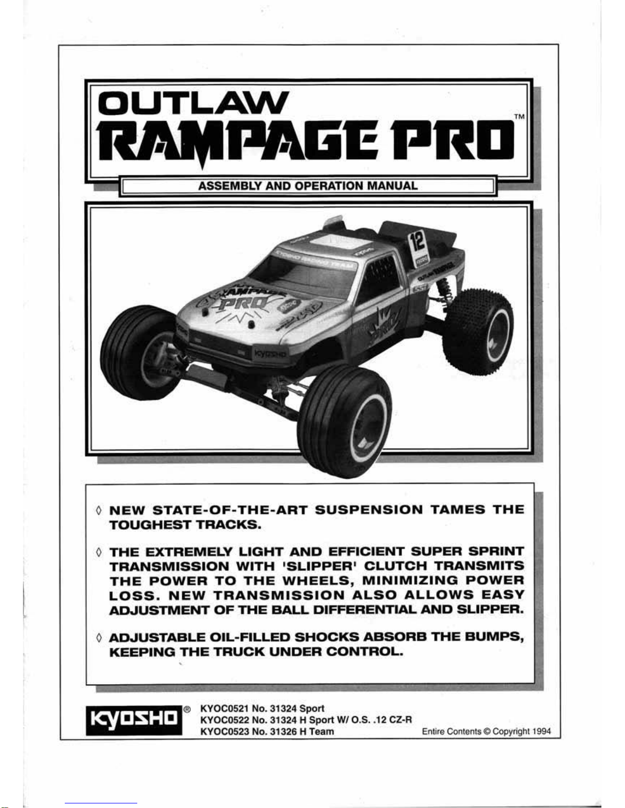
OUTLAW
0
NEW
STATE-OF-THE-ART
SUSPENSION
TAMES
THE
TOUGHEST
TRACKS.
0
THE
EXTREMELY
LIGHT
AND
EFFICIENT
SUPER
SPRINT
TRANSMISSION
WITH
'SLIPPER
'
CLUTCH
TRANSMITS
THE
POWER
TO
THE
WHEELS,
MINIMIZING
POWER
LOSS.
NEW
TRANSMISSION
ALSO
ALLOWS
EASY
AD.JUSTMENT
OF
THE
BALL
DIFFERENTIAL
AND
SLIPPER.
0
ADJUSTABLE
OIL-FILLED
SHOCKS
ABSORB
THE
BUMPS,
KEEPING
THE
TRUCK
UNDER
CONTROL.
® KYOC0521 No. 31324
Sport
KYOC0522 No. 31324 H
Sport
W/O.S
. •
12
CZ·R
KYOC0523
No.
31326 H
Team
Entire
Conte
nts@Copyright
1994
lq#IJSHIJ
Page 2
IMPORTANT: PLEASE READ THROUGH THE ENTIRE
INSTRUCTION MANUAL BEFORE BUILD
ING
THE OUTLAW
RAMPA
GE
PRO
.
We want your experience of building th
is
mode
l to be a
su
ccess.
So
before
you r
emo
ve
any
parts
from the
ir
pac
kages and begin assembly:
• Read through the entire manual carefully to make
sure
that you are thoroughly acquainted with the model.
• This instruction manual
is
for both the Outlaw Rampage
Pro Sport and Team Trucks . Differences in assembly
or
parts will be
not
ed as: (Team Tr
uck
Only).
• If for any reason you think this model may not
be
for you,
return
It
Immediately. Please N
ote
: Your hobby
dealer
cannot accept a m
ode
l kit f
or
return after assembly has
begun.
• The Kyosho Outlaw Rampage Pro
is
a sophisticated, high
per1ormance,
gas
powered off-road truck. Gas powered
RIC
trucl<s
are no more diffiCult to build and operate than
electric
RIC
trucks.
They
do
require a few
different
building
procedures
than
electrics.
If
you
follow
the
directions closely, the Kyosho Outlaw Rampage Pro will
provide many years
of
competitive RIC truck racing.
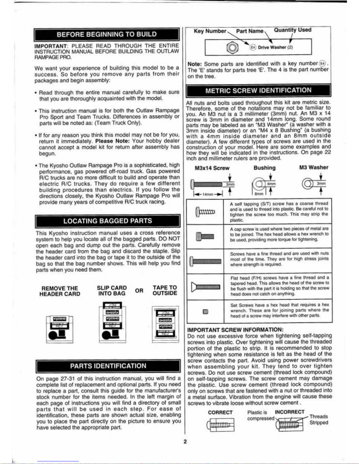
Key
Number~art
Name \
Quantity Used
I
(§)
" @
Dri:'washer
(t I
Note
: Some parts are Identified with a key number@ .
The
'E'
stands f
or
parts tree
'E'.
The 4
is
the part number
on the tree.
METRIC SCREW IDENTIFICATION
All nuts
and
bolts used throughout this kit
are
metric size.
Therefore, some
of
the notations
may
not
be
familiar to
you.
An
M3 nut
is
a 3 millimeter (3mm) nut. An M3 x 14
screw
is
3mm
in diameter
and
14mm long. Some round
parts may
be labeled as an 'M3 Washer" {a washer with a
3mm
lns
1de
diameter)
or
an '
M4
x 8 Bushing" (a
bus~ing
with a 4m
m insi
de diame
ter
and
an
8mm
outs1d e
diameter). A few different types of screws are used
In the
construction
of
your model. Here are some examples and
how they will be indicated In the instructions.
On
page 22
Inch and millimeter rulers are provided.
M3x14
Sc
'rew
Bushing
M3
Washer
~
A self tapping (SIT) screw has a coarse lhread
and
is
used
to
thread into
plastic
..
86 careful
not
to
tight
en the
screw too
much
. l his
may
strip tho
pla
stic.
This Kyosho instruction manual
uses a cross
reference
'=--
system
to
help you locate all
of
the bagged parts.
DO
NO
T
~
A
cap
scrow Is usod wllcre two pieces ol molal
are
to
be
jo!nod. Tho
l>ox
head
allows a hex
wrench
to
be
usod,
Pfovldong
more
10<q0e
fa<
tightening.
open each bag and dump out the parts. Carefully remove
the header card from the bag and
discard the staple. Slip
the header card into the
babeg
ohr
tape T
itht?
the11ohuts1 ide of0thed
ft'luMI!MM
bag
so
that the bag num r s ows. IS
w1
e p you
1n
~-
Screws
haw
a
fono
thread
and
are used wilt! nutS
most of tn.
umo
.
Thoy
are
lor high slress joll1ts
where
strength
IS
required.
parts when you need them.
RE
MOVE THE
HEADER CARD
SLIP CARD
INTO BAG
OR
TA
PE TO
OUTSIDE
On
page 27·31 of this instruction manual, you will find a
complete list of replacement and
optional parts.
If
you need
to replace a part. consult this guide for
the manufacturer's
stock number for the items needed.
In the left margin
of
each page of instructions you will find a directory
of
small
parts
that
will
be
used
In
each
step.
For
ease
of
identification, these parts are shown actua l size, enabling
you
to
place the part directly
on
the picture to ensure you
have
se
lected the appropriate part.
2
Aal
head (FIH)
acrows
have a
fine
tf1read
and a
1apered
head.
This
allows tho
head
ol the
acrow
10
be
!lush wllh lhe pan h
Is
holding so lllat lhe
acrow
head doos no1
C4tch
on
anything.
llJJ)
Set
Sc<ews
have a nex
head
that
requ
ires a
heX
wrench.
TheM
are
for
joining parts where the
head
o1
a SCtttW
may
intorf""' wilh other paru.
IMPORTANT SCREW INFORMATION:
Do
not
use
excess
ive
force when tightening self·tapping
screws into plastic. Over tightening will cause the threaded
portion
of
the plastic to strip . It
is
recommended to stop
tighteni
ng
when some res istance Is felt as the head of the
screw contacts the part . Avoid using power screwdrivers
when
assembling
your kit.
They
tend
to
over
tighten
screws.
Do
not use screw cement (thre
ad
lock compound)
on
self-tapping screws. The screw oement may damage
the plastic.
Use
screw
cement (thread lock
compound)
only
on
scre
ws
that are fastened with a
nut
or
threaded into
a metal
sur1ace
. Vibration from the engine will cause these
screws to vib rate loose
wijhout screw cement .
CORRECT
INCORRECT
l:jtt\ittltii""J
Page 3
•
I
Some precautions need to be obseiVed when building your
Kyosho kit to avoid problems:
1)
Take
your
lim
e and
read
the instrucllon
manua
l
thorough
ly
.
2) Try to avoid working over a deep
pile carpet. tn the
event that a small part or screw should fall onto the
carpet,
it
would be difficult to find. ·
3)
Place a mat
or
towel on the work surface where you
will be building
the kit. This will prevent parts from
rolling off and
will protect the work surface at the same
time.
4) Avoid gening products like motor cleaner or screw
cement
on
the plastic parts . They can melt the plastic,
which
will damage the model.
5)
Avoid running the model in very cold temperatures.
Both plastic and
met
al
parts become brittle at low
temperatures. In add i
ti
on, grease and
oil
beco
me
thick, causing premature wear and poor performance.
6) Remove all flashing from parts before assembly as
shown
in
the example below.
~
Donot
~
removeUM
tl
u hlng wfth
tMCUHet.
STEP2
UM•Wrp
hobbykrifo
to lrlm
the
RashoH.
INCO
RRE
CT
7) Trial fit all parts
to
ensure propec fit before anachi
ng
them permanently.
8) IMPORTANT! Note the Grease, Differential Grease,
Screw Cement and Instant Glue (CA) symbols used
throughout the manual and apply where shown.
Diff. Grease
If
Y<HJ
use
N
idcel
CadmiUm
Batteries
In
the
Cli:!.
radio
system,
they
must
be recycled
or
r>
-:-o
d
isposed
of
property.
'ClO
NICd
...
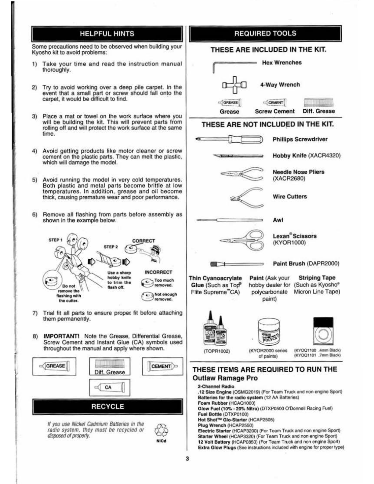
THESE ARE INCLUDED IN THE KIT.
r
..:r
G-
u
Grease
Hex Wrenches
4·Way Wrench
c([
caoEHT
~
I!!!JiJillB
Screw
Cement Diff. Grease
THESE ARE N
OT
INCLUDED IN THE KIT.
••
'
[ l
~
Phil
lips
Screwdriver
Hobby K
ni
fe (XACR4320)
Need
le
Nose Pliers
(XACR2680)
Wire Cutte
rs
Awl
Lexan•
scissors
(KYOR1000)
Paint
Brush
(DAPR2000)
Thin
Cyanoacrylate
G
lue
(Such as Toll"
Flite Supreme - CA)
Paint (Ask your
hobby dealer for
polycarbonate
Striping
Tape
(Such as Kyosho•
Micron Line Tape)
3
paint)
=
...
-
90L'i(J'
(TOf'Rt002)
(
KYOR2000
series (KY00
1100
.....,. 8laciQ
of paints) t
KY0011
0t
7mm
8laciQ
THESE ITEMS ARE REQUIRED
TO
RUN THE
Outlaw Ramage Pro
2-<:
hannet Radio
.
12
Stu
Engine (OSMG20t9) (For Te
am
TNCI<
and non
engtnO
Sport)
Ba
Horiot
for
the redlo ayatem
(12
AA
Banolies)
Foom Rubber (HCAQfOOO)
Glow Fuel (1
0%.
20% Nitro)
(DTXPOSOO O'Donne
ll Racing
Fuo
l)
Fu
el BoHle (
DTXP0100
)
Hoi
Shot'
M Glo-Start
•r
(HCAP2505)
Plug Wreneh
(
HCAP2550
)
Elect
ric
Starter (
HCAP3200
) (For
Team TNCI<
end
non engino Sport)
Starter Wheel (H
CAP3320)
(For
Tea
m T
ruc
k and non engine
Sport)
12 Volt Banory (
HCAP
0850)
(For Team Truck and non
et1lJ
ine Sport)
Extn1
Glow Plugs (Soolnslruetions included with
engine
for propor
type)
Page 4
l
•
for
90
daY$
after you pur
Chase
your Outlaw Rampage Pro, Kyosho will
eittleJ repair
or replace,
at
no
charge. any inoor rectly made part.
•
Make
sure you SAVE
THE
AECE
IPT
OR INVOICE
you were given
when
you
bought your model! It's
your proof
oJ
purchase •
and
we most
see
11
befoce
we
c-an
honc)tthe warranty.
•
To send yout Outlaw
Rampage
Pro In for tepairs
covered
under warranty,
you
shou
ld
send
your truck to K
yoshO's
avtllorized U.S. tepair f
acility:
Hobby Services
1610 Interstate Drive
Champaign,
Illinois
61821
Attn. Service
Oepa
.rtment
Phone: (217) 398·0007 9;00 A,u,
·5:00P.M
. Central Time M·F
• For
deta
ils
on
your return,
be
sure
to
follow steps
HI
under the •Repair
Serv
ices Available
Anytime•
seclion.
Limit
of
our Liability:
Ou
r tiability under this warranty
ls
limited to the repair
or
rep
lacement by
Hobby
Services of defective
parts
and docs notlnclode
cost
of
shipping
to
us.
Hobby SetVices does pay the shipping
oxs>ense
to retum warranty Ite
ms
to
yoo
.
Exclusion and/or Voidance
of
Watranty:
This
wa1ranty
ooes not apply to damage
or
dofcc.
ts
cosui1J~
trom mi
suse
.
abtlormal service, damage in &hipment, damage resulting
from
a crash,
or
da
mage
to
tho truck caused
by
the batteries. The warranty Is
V¢kjecf
If the
model
Is
mOdified.
altered. or
repWred
by
anyone
otheJ
than Hobby
SetVIces
.
This
warranty gives
you
specific legal rights. and
you
may
have
other rights
thai
va.JY
!tom
sta
te
to
s.14ite within t
he
U.S.
We
ate sotry, but
we
cannot
be
respons
libte
fot
crash damage and/or resulting
sass
of kit
s,
engines, mdios.
accessories.
otc
,
Ropalt
SOrvlcos
Avallt~ble
Anytime:
After
the 90·day watranty has expired, you can still have your Outlaw
Rampago
Pro tepalro<l
lor
a small
cha
rge
by
1.he
ex;perts a.t
Kyosho't>
authorized
U.S
. topair
facil
ity, Hobby Services, at the
address
listed unde r
Warranty I
nformation
.
•
To
speoo
up tho repair process,
please
tolklw the lnsltuctlons list
ed below:
1.
Und~
all circ
umstancGs. r01
um
the
ENTIRE
system: truck
and
radio.
2.
Make
sure
the trans
mitter
is
turned
off
and
all
batteries
are
diSCOnnected.
and all
fuel
is drained f
rom
ltle fuel tank.
3.
Send
written instructions which include: a O
st
of all It
ems
retvmed. e
THOROUGH
explanation of tM problem and tho service
nee<led.
and
your
phone
nu
mbEH
whe1e
you can
be
reachod during the
day
.
If
you
expect
your repair
to
be
covered
ur"'dor
warranty.
be
su
re
to
Include
proof of date of purc
hase (your stote receipt
or
pur~aso
Invoice).
4.
AlSo Include your lull ret
urn
addr
ess.
Aepalr ch
cuges
and postage may
be
ptepaid
or bill
ed
C.O.D. All repairs.
shipped outside the
UnitGd
States must
be
prepaid In U.S.
funcls only.
SpeeiftcaUon end
De
scription Changes
All
pictures. descrip tions and
speci.ticatlons
found
in
chis
1nstructlon manual are
subj~t
to change without nolice. Kyosho maintains
no
responsibility for
inadvertent errors in this manual.
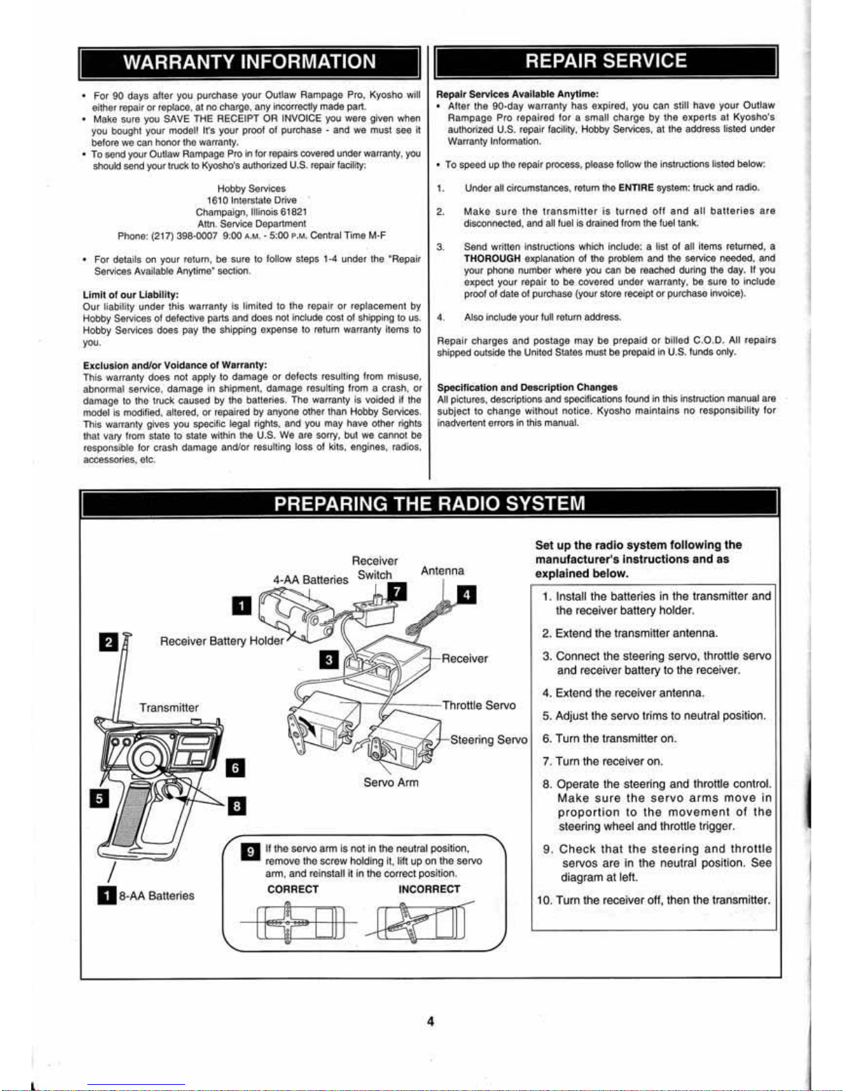
PREPARING THE RADIO SYSTEM
B
Transmitter
8-
AA Batteries
D
Receiver
Batteries Switch
~'
Set
up
the
radio
system
following
the
manufacturer
's
Instructions
and
as
explained below.
1.
Install the batteries in the transmitter and
lhe
receiver battery holder.
2. Extend the
transmi«er antenna.
3. Connect the
steering servo, throttle servo
a
nd
receiver battery to the recei
ver
.
4. Extend the receiver antenna.
5. Adjustlhe servo trims to neutral position.
-}-Stole ring Servo 6. Turn the transmi«er on.
Servo Arm
au the servo arm Is not in
the
neutral position,
remove the scr
ew holdi
ng
it, lift
vp
on the sorvo
arm, and
roinstalf 1t
In
lhe correct position.
CORRECT INCORRECT
rFfF
I
Ill
JPifiiT
4
7. Turn the
recei
ver
on
.
8. Operate the steering and throttle control.
Make sure
the
servo
arms
move
In
proportion
to
the
movement
of
the
steering wheel and throttle trigger.
9. Ch
eck
that
the
steer
ing
and
throttle
servos are
In
lhe
neutral position.
See
diagram at lett.
10.
Tum the receiv
er
ott, then the transmitter.
Page 5
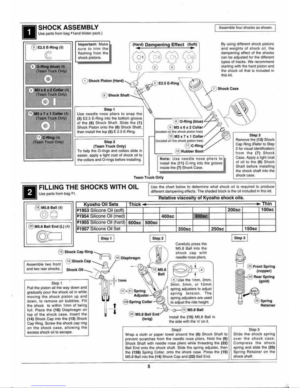
Assemble four shocks as shown.
0 E2.5
E·Ring
(8)
Important:
Make
(Hard)
Dampening
Effect
(Soft)
By
usi
ng
different
shock
pistons
suro
to trim
the
and wei
ghts
of
shock
oil
, the
~
flashing f
rom
the
@
,
...
_
.....
.-..
.....
.
..
-
.....
dampeni
ng
effect
ol
t
he
shocks
. '
. . . .
shock pistons.
: : .. ~ 2
~
\ :
..
~1
J
:
.-.2
'
can
be
adjusted for the different
. ·-.
. . . .
..
·
..
.
-·
'
•
' ' ' '
tYJ)eS
ot ttaeks. We recomroond
0
0411ng
(blue)
(8)
· ... -
...
'·
.,..,.·
..
...
-·
0 0 0 0
starting wl
111111o
!lard piston and
(T
~
Only)
the
shock oil that is included
in
111is
klt.
0 s
E2
.5 -
'"9
~~X
llllZ
coa.r
(4)
0
shOckPiston(Ha
rd)
~
~
ER
'
,
..
<
. ,
(~
1
Shock
Case
. .
cr...,
Trude
OnfY)
0
Shock
Shalt
'~
.
®rt
~
~
~
118x7
x 1
coa.r
(4)
Step
1
~
Use
needle
nose pli
ers
to
snap
the
(T~rude
Only)
(5) E2.5 E·Ring Into t
oo
bottom groove
0 O·A
ing
(blue~/
*
TI
of
tho
(6)
Shock
Shalt
. Slide
tho
(1)
Shock Piston onto
111e
(6)
Shock Shall,
{!)
M3
x 6 x 2
Collar
tnen Install the top (5) E 2.5 E·Aing. (l
oe&
tod on the shock piston t
ree
)
~
Cofllng
(4)
- @
M3
x 7 x 1
Collar
Step
3
(T...,
Trude
enly)
Step
2
(located on t
he
shOC:k
piston
uee
)
Remove the (13) Shock
c
(Team
Truck
Only)
@
C·Ring
Cap Ring (Refer to Step
To help t
he
0 -rings
e.nd
ooflars slide in
@)
Rubber
Boot
2tor
Visua
l ldentiflcallon)
easier,
apply a llghl ooat of
Shoe!<
otl to
lrom lhe
(7)
Shock
Case. Apply a
Jighl coa
t
lhe collars and O.rings b&loro Installing.
Note
: U
se
need
le
nose
pli
ers
to
install the (
11
) C-ring
ln1o
tho groove
ol
oil to
the
(6)
Shock
inside
111e
(7) Shock
Case
.
Shal1 before installing
t
he
shOck
shaft into the
Team
Truck
Only
$hOek casa.
1
•·•1
~.~L!.~~
o
~~~
t
~
SHO
C K S
WITH
OIL
Use the chart betow to
detem
'li
ne
what shock oil
is
required to produce
different
da.mpen
il)9
elfeC1s.
The
shaded block ls the oil included in this kit.
Relative VIscosity
of
Kyosho
shock
oils.
@)
M5.8
Ball
(8)
Kyosho
Oil
Seta
Thick
Thin
@6)
N1
953 Silicone Oil (soft)
200sc
100sc
N1954 Sil
icone Oil (med)
400sc
300sc
@)
M5.8 Ball
End (L) {4)
N1955 Silicone Oil (hard)
soosc
500sc
N1957
Silicone Oil Set
©0
l
step1
1
@ Shock Cop
Ring
"[r=:u
.-------:-
--,
11.\
shock
Cap
Assemb
le two hont v.;;
and two
rear shOCks
.
I
Step2
1
I
.....
350sc
Carefully press the
M5
.8 Ball
1nto
the
shock
cap
with
needle
oose
pilo
ts .
250sc
,---
-,...---
--;--
--,
"'--~
ID=*=1mm
Sl
ep
1
\O
}>,
.Gv
.,.,
eall
@PT
0
0
Use
the 1 mm, 2mm,
3mm
, Smm.
or
10mm
Pull the piston all the
way
down and
gradually pour t
he
shock oil in
whUc
moving
the
shock
piston
up
and
down. to remo
ve
air
bubb
les. F
ill
the
sha<:k
to wlthln 1
mm
ol
being
lull. Place the
(16)
Diaphragm
on
top of
lhe
shock
case. lnsen lhe
(14)
Sllock Cap into the (13) Shock
Cap
Ring. SCrew
the
shoclc cap ring
on
the
shock
caso
, a
llo
wing
the
excess shock oil to escape.
t
--.
Adjuster
spnng
tsnston
. T
he
sptlng adjusters a
re
used
@ spring
Collar
to adjust the ride height.
~~
M5.8Boll
@ Ms.8 Boll
End
~
(long) Install
lho
(15) M5.8 Ball in
the
side with t
he
•a•
on
it.
Step2
Wrap a
clo
th
or
paptH towel aroun<f the (6) Shock Shaft
to
prevent sctatches
hom
the neodle nose pliers. Hold the (
6)
Shock
Slla
ft wilh noodle nose pliers whi
le
threading
111e
(22)
Ball End
onto
the shock shaft. Slide the
SP•ing
adjuster. then
lho
(128) Spring Coll
ar.
onto lhe
Shock case. Press tho (15)
M5
.8 Ball into the (14) Shock Cap and
(22)
Ball End.
5
150sc
I
Steps
I
~
@
Fron
t
Spring
(copper)
Step3
Slide
the
shock
spring
o
ver
tho
shock
caso
.
Compress
the
shock
spring
and slide tho (25)
Spring
Retainer
on
the
shock
slla~
.
Page 6
L .
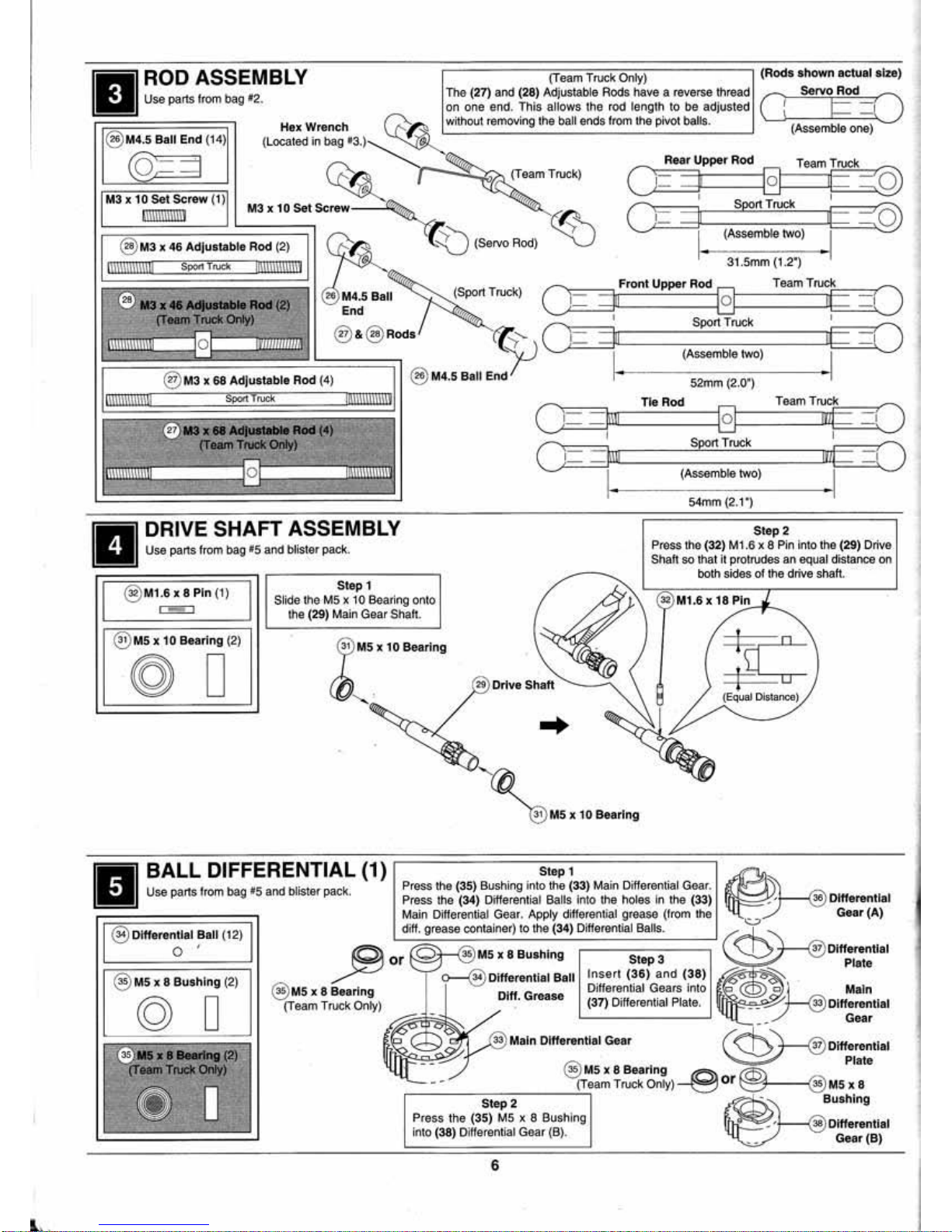
ROD ASSEMBLY
U
se
parts trom
bag
12.
54mm (2.1·1
DRIVE SHAFT ASSEMBLY
Step 2
Use pans
from
bag
il5 and blister pack.
Press the (32)
M1.6
x 8 Pin Into the (29) Drive
Shah
so that
it
protrudes
an
equal distance
on
both sides
of
the drive shatt.
@ M1.6 X 8 Pin (
1)
I - I
® MS X 1 0 Bearing (2)
@ D
@
MS
X 8 Bushing (2)
© D
Step 1
Slide
t,.,e
M5 x tO
Bea
ring onto
the
(29) Main Gear
Shah
.
@)
Msx
10
Bear
ing
..
\31l•MSx 10 Bearing
Step 1
Press the (35) Bushing into
the
(33) Main Differential Gear.
Press the
(34)
Differential Balls into the holes In the (33)
Ma
in OifferentiaJ
Gear.
App
ly differential grease (f
rom
the
ditf.
grease
container)
to
the (34) DifferootiaiBalls.
)9or
@
M5
x 8 Beari
ng
(Team T
ruc
k Oflly)
Dfff. Grease
6
Step3
l
nsen
(36)
and
(38)
Differential Gears Into
(37) Differential Plate.
~~·1--
--<'0)
Ditferentla
l
Gear (A)
Plate
Ma
in
Gear
Plate
Gear (B)
Page 7
II
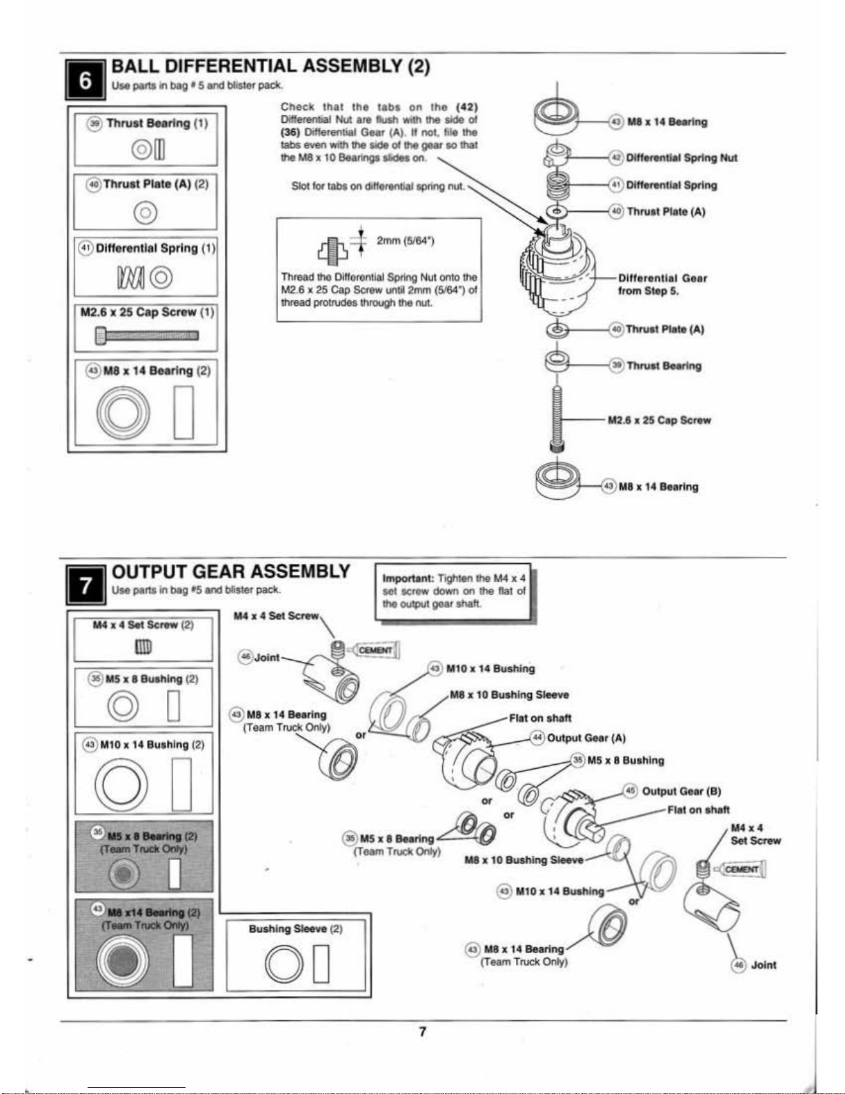
BALL DIFFERENTIAL ASSEMBLY (2)
use pans In
bag
• 5
and
blister
pack.
@)
Thrust
Bearing
(t)
@
Ill
@ Thrust Plate (A) (2)
@
@ Differentia l Spring (1)
m©
M2.6 x 25 Cap Serew (
1)
@
I I
@)
M8 x 14 Bea
ri
ng
(2)
0
D
Cheek
that
the
tabs
on
the (42
)
Differen1181
Nut
are
1\Jsh
"'"'
tho
-
o4
(36)
Oiffere<~tial
Gear (A).
If
not. file
the
tab5
oven
"''h
tho
- of
tho
gear
so
that
tho
M8
x 10
BeaMgs-
on
.
~
4
2mm (5184")
Thread the
Dltlor
entlal Spring Nut onto
tho
M2.6 x
25
Cap
Screw
un~l2mm
(5184")
o4
thread
protrudes
througl\
the
nut
.
~~
~1'-.:J'-
Dlftor
enllo
l Goar
from
Stop
5.
ci!ii+--
--1.40\
'rllnuot Plato (A)
~
ThruotBearlng
>--
- M2.6 X
25
Cap
Screw
~
M
B
x
14
Be
aring
OUTPUT GEAR ASSEMBLY
Important: Tighten
tho
M4
x 4
sot
SCfOW
down
on
tho
flat
of
tho
OUtput
gear
slla.ft.
Use
pans
In
bag •5
and
blister
paek.
M4 x 4
Set
Screw
(2)
ll1D
@>
Ms x 8
Bushing (2)
© D
@)
MtO
X
14 Bua
hlng
(2)
OD
..
.....
-.
(2)
(T-
TNd<
Orfy)
M4
x 4
Set
Scnow,
@
Me x 14
Bearing
(T
earn
Truek Only)
"0
0'
Bushing
Sleeve (2)
OD
7
MB
x 10 Bushing Sleeve
@)
M
10 r 14 Bushing
@)
MB x
t4
Bea
ring
~
(Team Truek Only)
Ot
Joint
Page 8
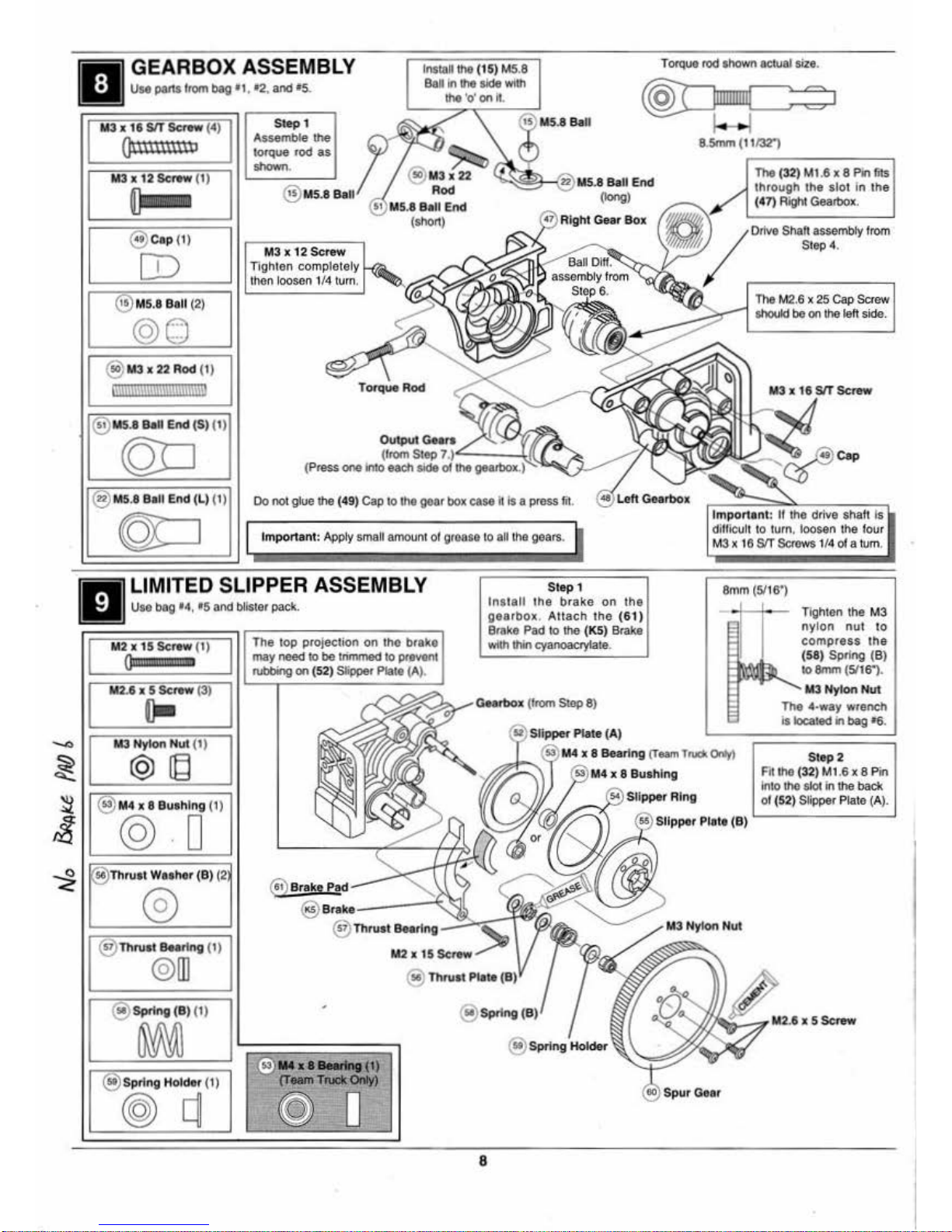
GEARBOX ASSEMBLY
IM18111h8
( 1 5) M5.8
Ball
In
111e
aide with
the
'o'
on
11
.
Torquo rod shown
&c:tual
size.
Use
pans
from
bag
•1,
t2
, and
•s..
@]C:::Jm
llllllHIIII
~IIII=~:
~=~I
~
M3 x 12 Screw
(1)
~
@
cap
(1)
[D
@)Ms.e
Ball
(2)
@Q
@)
M3x
22 Rod (1)
6\11\i\lmlllllll\\\\lmm
@ M5.8
BaU
End
(S) (
1)
(QO
@ M5.8
Boll
End
(L
) (1)
©D
Step
1
Assemble
the
torque
rod
as
shown.
~~--{i22
M5.8
BaU
End
M3 x 12
Screw
Tighte
n c
ompletely
then loosen 114 tum.
T<><queRod
Do
no
t glue lhe (49) Cap
to
the
goer
box case k Is a press
fit
Important:
App
ly
small amount of groase to all t
he
gears.
(long)
8.5mm
(11/32")
The
(32) M1.6 X 8
Pin
fils
through
the
slot
in the
( 4 7) Righi Geart>ox.
Important
: II
the dri
ve
sha
h Is
ditficull to t
urn
. loosen
the
four
M3 x
16
SIT
Screws 1/4
of
a tum.
LIMITED SLIPPER ASSEMBLY
Step
1
8mm
(5116')
Uso bag
•4,
•s
and
blister pack.
Install the
bra
ke
on the
gearbo
x.
Attach the
(61)
Brake Pad to lhe (KS) Brake
with lllin cyanoaaylate.
M2
x 15 Screw
(I)
Qllillill§!i!§iJ!I*
M2.6 x s
Sc
rew
(3)
o-
.._,.
MJ
Nylon
Nul
(1)
~
@
ltd
~
@
M4
x 8
Buahlng
(1)
i © '0
..
Thrust
Was
her
(B)
(2
@
@
Thruat Baorl
ng
(1)
©
rn
@ Spring (B
)(
I)
~
@)
Spring
Holder
(! )
(@)q
The
lop
projection
on
tho
brako
may
need
to
be
lrimmed
to
pr.GVGnt
rubbing
on
(52
)
Sipper
Plate
(A)
,
®
~;Iipper
Plat
e (A)
x 8
Bearing
(Team
T-
Onl1)
@
Brake
Pad
@
Brak••
---4.~
@
Thru•t
Baoring
~~....:-t
•
..
........
lng(1)
(TMRI
TIUCirOnly)
~
(]
M2x15Scnow
•~
@ Th
rv
tt
Pllta
@ Spring
@
sprtng
Holder
8
(eo)
SD
'"' Goer
Tighten
the
M3
nylon nut
10
compress
the
(58)
Spring
(Bl
to
8mm (5116").
M3NylonNut
The
4-way
wrench
1s
loca1ed in
1>a9
•s
.
Step 2
Fit the (32) M1.6 X 8 P
in
Into t
he
slol in
lhe
back
of (52) Slippar Pl
at
o (A).
Page 9
..
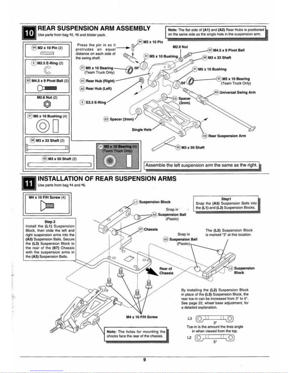
REAR SUSPENSION ARM ASSEMBLY
U
se
pallS
from bag
02,
•6 and bllsler pact<.
@
1112 X 10 Pin
(2)
0
111
2.5 E-Ri
ng
(2)
<6
®
M4
.5 x 9 Pivot
Ball
(2)
0
M
UNut
(2)
0
@ Ms x
10
Bushing
(4)
@0
@)
Roar
Hub
(Right)
@ Rear
Hub
(Left)
0 E2.S E-Ri
ng
@)
Specor
(3mm)
~
Single Hole
@)
111
3x
33
Shalt
(2)
'---
-~~
~~~~~~
n
rn
~
••IIateM
u
---01111
Note:
The
Pat
side
of
(A
1)
and
(A2)
Rear HubS
Is
positioned
on
the
sa
me side
as
the
single
hole
in l
ha
susponsJon
arm
.
IA----(ii)
Ms x
10
Beorlng
~
r
w-
- (Te
am
Trucl<
0011
y)
e3
Universal Swi
ng
Arm
to
Rear
Suspension
Atm
I O @
M3xSOShah
(2) I @ 0
Assemb
le the left suspension
arm
the
same
as
the
right.
INSTALLATION
OF
REAR SUSPENSION ARMS
Use
pallS
from
bag
••
end •6.
1114
x 10
F/H
Screw
(4)
[)mm
Step2
Insta
ll
the
(L1)
Suspension
Bloc
k,
llw>n
Slide
the leh
~t
_..;on
arms
Into
(A3) Suspension Bals. SeouroJ
tile
(L3)
Suspension Block
to
t
ho
roar
of the
(67)
Chassis
wilt\ t
he suspension arms
1n
1110 (A3
) Suspension Balls .
Suspension
Block
512p1
Sn
ap
in ·
;>'' (7!;
--:
;::::'\el
Suspension
Ball
(Plastic)
Snap
t
ho (A3
) Suspension Balls into
tllo
(L
1)
end
(L3)
Suspension Blocks.
Snap
in
The (L3)
Suspension
Block
Is marked -:r
8l
INs location.
@)
Suspension Ball
Note: The hol
es for
mounl1ng the
shocks faoo
lhe
rear of the c
hassis
.
9
By installing
tho
(L2) Sus
pension
Bloc
k
in plaoo of tho (L3) Suspension Bl
ocl<.
the
rear toe-In
can
be
lncr
eased
fro
m 3' to 5
'.
Sao page 22, wheel base adjustmen t. l
or
a detailod explanation.
L3
(QJII
11
\2)
3'
T oe-ln Is tile amount
lhe
liras angle
Ill
when
viewed from lhe
top
.
L2
(QJ
II
s•
II
J2)
Page 10
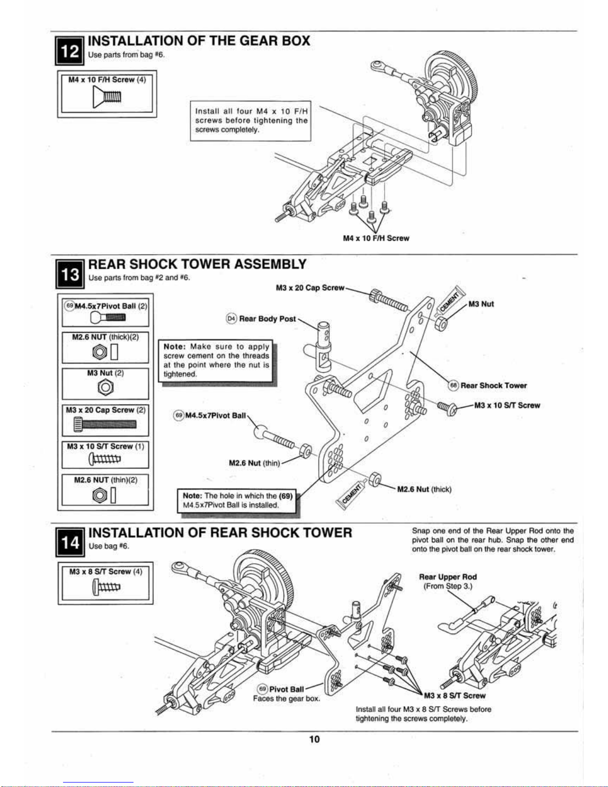
INSTALLATION OF THE GEAR BOX
Use
parts from' bag •6.
M4 x
10
F/H
Screw
(4)
[)mnn
Ins fall
all
four
M4
x
10
F/H
screws
befo
re
tightening
the
screws completely.
fttl
~~!~
r
!~?.~~J.O
WER
ASSEMBLY
~
M3 X
20
Cap
Sc"'w
@)14.Sx7Pivot
Boll
(2)
~
@)
ReorBody
Post
M
2.6
NUT
(1111ck)(2)
©l
D
N
ote:
Make
sure
to
apply
screw cement on lhe threads
I
M3
Nut
(2)
@
I
at the point whe(e the nut
is
tightened.
M3 x
20
Cap
Screw
(2)
@M4.
Sx7Pivot
Ball
't?
~I!MIIMII!
!
M3 x 10 SIT
Screw (1)
O;llm~
M2
.6 N
ut
(l/1in)
M2.6 NUT (l/1in)(2)
.
©lO
Note:
Tho
hole
In which the
M4
.5x7Pivot Ball Is Installed.
(69)
INSTALLATION OF REAR SHOCK TOWER
Use
bag
•s.
M3 x 8 SIT Scr
ew
(4)
ijJn®
@ Pivot Ball
Faces the gear box.
10
0
0
es
Rear
Shock
Tower
Snap one end of the Rear U
pper
Rod onto the
plvoo
ball
on
l
he
rear hub. Snap the other end
onto
the
pivot
batt on the
rear
shock tower.
Rear Upper
Rod
(From Step 3.)
M3
X 8 SIT
Screw
Install all four
M3
x 8 SIT Screws before
ligh
tening
oho
screws completely.
Page 11

lil!!l
FRONT HUB ASSEMBLY
~
Use parts lrom
bag
"2 and blister pack.
R
ight
Knuckle
@)
M4.5 X 7 Plvo1
8<1
11
(2)
Arm
0:-
i
_j_
·-
@
1114
.5
X 9
Pivot
8<1
11
(2)
Step\
T - ·
Tm1
il'e-
~
0
area
lrom
(12)
Threa.d
lhe
M2.6 Nul on untU
1
mm (3/64")
ol
1hroad
sho
ws
above
the nut
....
' • x 7
Plvol
Ball
(
~
"'!9
1114•
Step2
Instal
the
(70
) Front
AXle
in
the
(12) Ri
ght
Knuckle
Arm. The
Right
Knuc:lde
@)
E3
.0
E-Alng
(2)
Aim
as
shaNn.
M2
.6
~
""'
=
1114
.5
,.
I
8<111
x9Pivo
Nut
hole through
(70)
Front Axle Is
dril
led
at an angle.
line
up
the
ho
le In the axle and knuckle
~
l
A
~
./
\!9
1114
X
'Z7
Shaft
(2)
Step3
Sllde
tho
Rigl\t Knuckle Arm aOMmbty Into
the
(11)
Right Front
Hub
and
secure
it with
m
tho
(71)
M4
X
'Z7
Shalt.
Nola
tho angje
ol
tho
lront axle shown in the diagram below.
~
@>
Front
@~
~
M2
.6
Nut
(4)
@ Ri
ght
Knuckle
~~
-
Ri
ghi
Front
Hu
b
Step
4
©l
(
Marl<
od
with
an
'A')
'ft
E·Ring
\
·
·-~-
·----------------
--------
---------
------
-----------
-------
------
Step\
Left Knuck
le
@ MAx27Sha Trim tho
(1
3) Left
Knuckl<l
Aim
Arm
tho aamo
as
the
(1
2) Ri
ght
It
Knuclclo
Aim
as
shown
above
.
@ M4.5 X 9
Pivot
Ball
~
Step2
lnstaQ
tho (70) Front
AxlO
in
tho
(13)
Lon Knuckle Arm.
M2
.6
Nut
Step3
Slide the left knuckle arm
@
Left
Front
Hub
usembly
into
the
(14
J
LO~
F rent
Hub
and
secure ~ will
the
(71)
M4 x27 Shalt. Note
the
anglo ol
Step4
tho (70) Front
AXle
shOWn
In tho lns·lall the pivot balls In the
Insta
ll
tho pivot balls In the
knuckle
arm
assomb
ly.
~
M4.5
X 7
Pivot Boll
li~:ll.----
M2
.6
Nut
I
u
a Lett
KnuckJe
Arm
~
FrontAx
.
le
0
diagram at tho
righ
t knoolde
arm
assembly.
--
r
@)
E3
.0 E·
Ring
The
axle anglas down.
1M
INSTALLATION
OF
FRO
NT SHOC
K TO
WER
111!11
Usa
pat~Sircm
bag "2.
Step
1
I@>
M4.5 x 7
Pivot
Bell
(2)
0
M3 x
20
Cap
Screw
(2)
~
M3
X 8
f/H
SIT
Sc.-
(4)
~
M2.6
Nut
(thin) (2)
0 0
M2
.6
Nut
(thick) (2)
00
I
M3
Nut
(2
)
I
@
lnslal
al
lout
M3
x 8 FIH-SIT screws
before tighterWig
them
down.
@
Fron
t
Bulkhe
ad
Instal tho M3 x
20
cap
Screw
in
this
hole
..
11
Snap
the Iron!
upper
rods, lrorn Step
3. onto
tho
M4.5 x 1
piVot
belli.
Stop2
Install
the
M3 x
20
cap screws
and
the (
69) M4
.5 • 7
PM><
Bals
.
lmportont Instal
the
M3
X 8
F/H-s!T
acrews from the side wl
th
the
countersink
for
tne
he
ad
of
the
screw
to set ln.
l
Page 12

..
INSTALLATION
OF
FRONT ARMS
Use parts
11om
bag
02.
{D
E2.5 E·Ri
ng
(6)
(6
@ M3 x 27 Shott (2)
0 Dl
@ M3 X 44 Shalt
(2)
[U
Note: Chec
k that
the
suspension arms move
freely.
rr
they
do
not
locate
v.ilere they
are binding
and
hghtly
trwn
lhe
.....
Slep
1
Al!aCh
lhe
right
la>uclde
ann
8.-.bly
10
lhe
(H1)
FIOOI
S<_...aon
Ann
R;glll
KntJCkte
Ann
Assemllly
m
Step2
Attath tho (H1)
Front~
Arm to the (73) Front Bulkhead
with
the (75
) M3 x
44
Shalt
.
Secure
the
shall
with
the
(5)
E2.5 E-Rings.
Step3
Snap
lhe
front upper rods
onto
lhe pivot
bal
on
lhe
la>uclde ann assombly.
@)
11
3 x «
Shall
'
Assemble
lhe
left
side
""'
same
as
the
right
Bulkhead
1 E2.5 E·Ring
fMl INSTALLING
THE
FRONT
SUSPENSION TO
FRONT
CHASSIS PLATE
~
Use
parts from
bag
"2.
M4 x 10
Fill
Screw
(4)
[)um
Note: Install ell four M4 x
10 F/H
screws beforo tighleolng
them
.
Front
Cl\aulo
Plaia
Front
BumP«
1M
SERVO SAVER ASSEMBLY
~
U
so
parts
from
bag •3.
Slide
the (87) Servo Saver Spring over the
sorvo
savor
oseomb
ly
after installi
ng
servo
saver(C).
Use a Uat bladed scr
ewdriver
10
pry open (83) Sorvo Saver (A)
during
essom
bly.
12
Sorvo Saver (B)
Romove
111e
shadod portion of
(62)
Servo Saver (B).
Use
(84)
for
all
Futaba SOM>S.
®
@l
®
Use (85)
fOf
Ainronics.
(i)
KO and JR standard @
servos
.
&.
®
Use (86) for Alnronlcs
G)
and
KO
mini servos. O
Ss
----
--------------------------
7.
12
~------
------------
-----------
l
Page 13

1M]
INSTALLATION
OF
THE
SERVO SAVER AND MOUNTS
ON
THE SERVO
~
Use
pans
from b
ag
•a.
@ M4.5 x 7
Pillow
Ball (1)
o::-
M2
.6 Nut (2)
0
M2.6 x
12
srr
serew
(1)
On
uunh
M3
x 10 srr
serew
(2)
or
(3)
it
~
Thread
the
M2.6 n
ut
on
unfit
lmm
(31641
of thread shows
above
the
nut.
(3164")
@)
M 4.5 X 7 Pi
vot
Ba
ll
(3)
o::-
~
@:
~~
40mm
(1
.5)
II the servo you are
usi
ng
is 40mm
(1.5•)
,
u
se
the
(F2) Servo
Mounts (A).
0
Note
: Do not Install t
he
rubber
grommets and
eyelets
on
the
servo
.
M3Washer
~
M3
x 10
srr
serow
M Servo Saver Collar
M3 x 10 srr
serew
'-'
,c (For AlrtronieS Servos)
~~
Importan
t:
With the
servo
centered,
install
the
servo saver
90
° to the
side
of the
servo
.
M2
.6 x 12 SIT Screw
(For Futuba and
KO
Servos}
go
•
Steering
Arm
(
C)
N
ote
the dir
ection
of
(C3)
Steering Arm (C) when anached
to (C2)
Steering
Arm
(B).
Stee
ri
ng
Arm
(B)
M 2.6 Nut (3)
@ M4.5 x 7
Pivot
Ball Thread lhe M2.6 nul on the
(69)
M4
.5 x 7 Pivot Ball until
,
1
1
mm
(3/64
")
ot thr
ead
-'--
1
mm
shows
above
the
nut
on
all
M2.6 Nut T (3/&4") three pivot balls.
0
@ E4.0 E·Ring (2)
~
@
Ms
x 10 Bus
hing
(4)
@0
@ M2
Stoppe
r (2)
@IQJ
M3
x 3
Set sere
w (2)
I11J)
@M4.S
x 7
Pivot
Ball
---l;(
M2.6
Nut
.._,
,.,
@ E4.0 E-Ri
ng
~~---
1
@>
Steering
Link
age Brace- -,
@
MS
x 1 o
_But•hfng
'-..!1
~
or
@
MSx
10
Bearing
(Team Truck Only)
@)
M4.Sx7
Pivot
Ball
@>
Ms x 10
Bualhlng
~
or
@>Ms x 10 Bearing
(Team
Truck Only)
E4.0
Ring
:t-®
1
MS
x 10
Bushing
or
@
M5
x 10
Bearing
(Team
Truck Only)
(0)-.-{!09)
M4
.5 x 7
Pivot
Ball
M2.6Nul
#
@ M2Stopper -
~
0
Screw
Steering
Arm
(B) 81 M2
Stopper
T\'@;IM5
x 10 Bu.
shfng
or
t!)
Msx
10 Bea
rin
g
(T
eam
Truck Only)
~'----,@>steering
Post
Snap
the
Tie
Rods from
Step 3
onto
the (69) Pivot
Balls.
13
Page 14

ltSI
~~!!~~
m
L!
~!O
N
OF FRONT SUSPENSION ASSEMBLY TO MAIN CHASSIS
.
M3 x 10
F/H
Screw
(2)
r:-
M3 X 14
F/H·SIT
Screw
(2)
~·w"·
~t
....
Ut~~
M4
X 8 FIH
Screw
(2)
.
[)nn
If
using
Mount, in
@ Hold-Down
'111
(F3) Servo
~
stall
the
(F4) . '
hold~dow
n In the back '
of
(F3).
Step2
Install
th
e steering servo as
showt1
•
Make
suro
the
centerline
of
the
steering
servo
and
the
centerline
of
the
left
steering
lin
kag
e
are
parallel
.
St0<1rlng Servo
-v
1
1
Trv
' '
In
stall the screws
Into
the
front
holes.
Step 1
Install the front sus-
pension
assembly, the
IWO
M3
x 10 F/H and
M4
x 8
F/H
screws.
and
the s1eeri
ng
servo
before
lightening
the
screws
down
.
Use
screw
cement
on
lhe
M3
x 10
F/H
screws.
M3 x 14
F/H-SIT
Screw
(Anaclles servo)
M4
x 8 F/H
Screw
(Anaclles front cllassls)
W
caoENT
]P
M3
x 1 o F/H
Scrow
(Anaclles servo saver)
CLUTCH ASSEMBLY
hold
the
drive
washe
r
U
se
parts from bag
•7
and
bl
ister pack.
a
hex
wrench
In
the
hole
while tightening
M3 x 6 Washer (1)
@
M3
x 6 Cap
Screw
(1)
~
M3 x 16
Cap Screw (4)
~
M3
Nylon
Nut
(4)
©~
@ E7.0 E·Ring (1)
n
@
Ms
x a
Bea
ring
(2)
0 D
Note
: L
ay
the 1.5
mm
hex
wrench in
the
two
slots
in
the
top of
(100)
Pinion
Gear.
Hold onto
the
clutch bell and tighlen
1he pinion
gear
with
the
hex
wrench
.
The
0.
$ . . 12 CZ·R
do&s
not
require
the
flywhee
l spacer.
II
Install
ing
the O.S. 10FP with
recoil
starter
or
Enya
engine,
use a KYOC3538
1963
10
Flywheel Spacer (not lncfu<led).
i:;;;;~n•
M3
Nylon
Nuotl<:::ii
•
use
the
KYOC4723
*
·aA.'>.·
5
Pilot
Shaft (not included).
@
Clutch
@ Pinion Gear 48P/25T
@
MS
X 8
Be•orln~l,
M3
X 6
Wa1Sh<>r
--.:
14
To allow for
adjuslment.
do
not tighlen the
M3 Nylon Nuts
until Step
24.
If
an Enya Engine is goi
ng
to
be
installed
use
the
KYOC3455
'92309
Engine Mount (not inclu<led).
Pinon
Page 15

ENGINE INSTALLATION
Use parts from bag t4, t7.
M3 Washer
(4)
@
M3
x a
screw
(4
)
[pumm
M2.6
x25
Cap
SCrew (2)
~
rr
f/llfl.flill !l·l
l!.'il
ft
I
9
Exhaust
Adapter
St
ep 4
Install
lhe
muffler
as
shown
,
I
mportant:
Before installing the engine on
the chassis. check that
lhe
thro«le
cum
on
t
he
carburetor is
on
the l
eft side
, opposite
the
muffler.
U
it
is not.
cheek
the
inslructions
lnctuded with the engine
oo
removal
of
tho
carburetor. Reinstall t
he
carburetor with
tOO
t
hronte
arm
on
Lh&
lett side.
x
2S
Step
1
Install aJI four
M3
x 8 scrows and
washers.
Do
not
tighten completely
to anow for adiustment.
Washer
1M
FUEL
TANK
INSTALLATION
l'lil!l
Use
parts from bag •7,
M3
x
10
FIH·SIT
SCI'1!w
(2)
~
To
hole
in
Important: A more
secure
f
uel
line
fitt
ing
can
bo
achieved
by
using
a phillips
screwdriver
to
flare
the
pr
essure
i
nle
t
and
fuel
outlet hOles.
I
~
c
:::J
I
15
Step
2
Adjust
the
engine
so
that the (60)
Spur
Gear
is
centered on
the
(1
00)
Pinion
Gear
.
Ti
ghten
the
M3
x 16
cap
screws so
the
engine
cannot move
back and forth.
St
op
3
Place a piece
of
notebook
paper
between
tM
(60)
Spur
Gear
and (100)
Pinion
Geaf.
t
Slide the engine
over
to squeeze the
paper
between
the
gears. Tighten the four
M3
x 8
screws. Remove
the
pape
r. Th9 gears should
spin freely
with
no blnding.
Remove. one
at
a
time.
the
M3
x 8 screws. Place screw cement
on
tho threads
and
reinstall the screw.
The
other
three
M3
x 8
screws
will
prevent the
engi
ne
from moving
out
of
adjustment
The
screw
cement
must
be
us.ecf
or
the engine
will
Vibrate the screws loose.
t
ho
fuel
li
ne
under the
fuel tank.
Page 16

ltfJI
!~~
rts
~;!~;.
~~
STALLATION
Step2
M4
x 12
Screw
M3
x10 SIT
Screw
(2)
~
M4
x12
Screw
(4)
ijnuam
M4 x10 FIH
Screw
(2)
[)mnn
M3
x
10
SIT
Screw
(4)
~
Step 2
Plug the ser'los and receiver
switch Into
the
recetver.
Tum
tho
transmitter
and
receiver on
and
check that the servos are plugged
into the proper
receiver sockets.
Tu
rn
the receiver, I han tha
transmllter off. Bund le the servo
loads
toge
the
r with a (1 03)
ne
Strap and
cut
off the excess strap.
Step 3
Important: SeaJ
the
receiver In a
plastic
bag
or
use a Kyosho
Receiver Protector
i923
02KY
,
KG
or KP.
Then
sandwich the
rece
iver
between
a
piece
at
1/4 •
foam
rubber
to
protect
it
from vibration.
II'\StaU
the receiver
battery under tho radio plate.
Step 1
Tempora
rily
insta
ll
lhls
screw. It will
be
permanently
Installed
in
Step 28.
Install the (03) Front Body Post,
so lhal the holes
race
each other.
Top
Plate
M4 x
12
Screw
t"'-'
/
Slide
the
(1
08)
Top
Plate through
the
(72)
Front
ShOck
Tower.
M3
x 10 SIT
Screw
Front
Body
Post
Mount
~--======::;::-
M4
X
10
FIH
Screw
M3 x
10
SIT
Screw
Swhch Plate
Sc-rews
(In
cluded
with
Radio
System)
Switch
Plate
Step
1
Install the
Throttl~
Servo and Receiver
Switch.
•
Throttle
Servo
(Item
induded
with
radio
system.)
(Included
with
Rad
io
System)
,~'.Js.
·
Nota:
Do
not
............
_
gronvnets and
eyelets on
the
""""'
@>
Servo
Mount
---...,
I
nsta
ll a (K3)
Servo
Mount on the opposite
end at
the
seiVO
also.
Reulve
r
Switch
(Included
with
radio system)
Receiver B
attery
(Included
w~h
radio system)
16
~~
,.p-
.d>
"'~
'~
o'""
~
~'<-r:}'
Step4
Aftec
securing
tne
reoeiver
and reoofver battery to the
(L4) Radio Plate with the
(109) Large Strap,
C\11
off
the excess strap.
Note: Do
no
t crush
the
loam rubbe
r.
It
must
be
able to isolate the receive!'
from vibration.
Large
Strap
Page 17

RADIO PLATE INSTALLATION
Use parts lrom
bag
13, 14
and
16
.
M3 xtO
SIT Screw (1)
~
M3 xto
Screw (1)
~
M3
x10 F
IH
screw
(2)
l)mm
M3 x15
FIH
SCrew (1)
Dnnlll\lllllDIIm
Torque rod attached
to
gear
box
In 8.
M3 x10
SC<ew
1
screw,
befor
e
the
radio
plate.
Then
x 12
screw
--
M3 x
10
SIT
Screw
1M]
FRONT
AND REAR
SHOCK
INSTALLATION
~
Use
parts lrom bag 11.
M3
x12 FIH
Screw
(2)
[)11\\)!!UU!U
jj!
l
M3
x14
Screw (2)
&--
@
Shock
Collar
(4)
©
([]
@
M3
Plastic
Nut
(4)
{9)
§}
__..
-,
M3
x 14 Screw
17
/Note the
direction ol
the
/
(117)
Shock Collar.
The
~
largor end 1s against lhe
11
~
M3Nut.
Shock
Collar
Ci
L--
F
ront
Shock
(Copper
SP<Ing)
Page 18

IE!·JI
J!'p~
rts
~r!:'"~~
4.
~!
.
NKAG
E
ADJUSTMENT
Trim a servo arm (included with the
M3
x3
Set
S<:rew (2)
lDD
radio system)
to
the shape shown
below.
@
M2
Stopper
(2)
@§
M3
x 3
Set
Screw
16mm
@
M2Stopper
Step2
lnslall l
he
(112) Throtlle Rod in
lhe
top hole
of
the thronle
arm
if
using the O.S . . 1
2CZ
·R.
II
using
an
Enya
0<
O.S.
10FP
engine
, Install it in
lhe hole approximately 1
3mm
(
33164
')
from the center
of
lhelhrolllo
arm
.
14mm
(9116")
F
ull
Speed
Idle Speed
Cut
off the
end
of
the
(111)
Brake Rod
if
it
hils
the
(68)
Rear
Shock
Tower
.
Idle st
op
sctew
M2
Stopper
0
0
0
0
00~
Step
7
Warni
ng:
To preven t dirt fr
om
damaging your engine,
saturate
the
loam
fitter
material with
leftover
shock
oil
rrom this kit or use the special Kyosho Air Filter
Oil that is
sold separately, KYOC2032 .
Air
Fitter
Cap
Foam
Alter
A
ft
Filler
Case
Slide this end through
the Brake
and
secure
it
with
an
(81)
M2
Stopper.
throtUe
arm
.
Install the throttle
rod
in the hOle
16mm (41/64")
from
the
center
.
Move
the lhro"Je arm so that the carburetor is
open 1 mm
(3164"
),
as
shown
at Idle
speed
belOw. Wrlh
lhe
seNO centered. install !he S8NO
arm 9oo
to
the
servo
as
shown
. Make a 90°
bend In the Ulrollle
rod
at
the hole 1
6mm
(518")
outlrom
the
center
. Install the throtlle rod in lhe
hOle
of
the servo arm
and
s"""'"
ft
with
an
(81)
M2
Stopper. Cut-off
the
excess thrott
le
rod
above
!he
(81)
M2 Slopper.
------------------------------------
-
I
step
&I
Br
ake Adjustment
With
the
transrniuer
and
receiver turned on,
squeete
the throttle trigger to full speed. The
cal'buretor
bar
rel should be
fuUy
open. It the servo
arm
moves too
far
. the
throttJe
rod
will
benc
l. Move
the throttle
rod
in
1owards
the center.
one
hole on
ths
servo arm . If
your
ltansmitter
has
end poi
nt
adjustment, reduce the amount
of
servo
arm
movement. If the carburetor barrel does not open
far enough,
move
the throttle rod one hole closer
to
the
center
on
the
thrott
le
arm
.
Release the thronle tri9gcf.
The
carburetor should Push the throttle trigger forward.
The
throttle rod
be
open only 1mm
(3164")
. Adjust the idle
stop
shou
ld bend slightly and the
brake
should
move
screw
to limit the amount the barrel closes. The: against the (52) SUpper Plate (A).
Try
to rotate !he
brake shoukf have
no
pressure
on
it
a.t
idle. Adjust:
rear lites
. T
hey
should
bo
difficult to rotate.
By
1he
M2
Stopper,
so
it
is
touching the brl!ke lever. : adjusling the (81)
M2
Stopper
on
lhe
(111) Brake
:
Rod
. the amount
of
btaking
force
can
be
adjusted.
18
Page 19

1!11J
WHEEL ASSEMBLY
Iiiii
The
wlleel$
ate
under
lhe leXlll'l" body ~ lhe
box.
@ RN rT1re
Hint
: Drill two 118. brealhor holes
toward the Inside of
each
Whool
.
m
:~:
~
~
~~~~~~~:!!
t
?.~
~
M4
Fla~
Nylon
N
ut
(4)
@[§
@ Me X tO Bu5hl
ng
(4)
©0
M2 X 5
SIT
Screw (6)
{Jml>
Aea.r
Wheel
Small hole
In
rear
whea
l disk Ia
lor the
rearwhooL
M4
F
langed
Nylon
Nut
A$$ernble
owo
rronc
and
IWO
rear-
-
Hint: Drill
two
118"
breather holes
Iowan! t
ho lnsi<Ja
of each wlleel.
Re
ar
Wheel Dil
k
After Installing
the
lires
on the
wne.ts.
gtue
lho
~
res
lo the
_,
wllh
lhin
CA.
inslant type
grue.
F'rt
the (
64
) M2 x tO Pin Into t
ho
slo4
In
the back
c4
lhe (E4)
Drive
W
ashe
r.
or
Front
Wheel
®-B
M6
x10 Bearing
(T
eam
Trucl<
Only)
~
M6 x10
Bearing
(Team
Truc
k Only)
M4
Fla
nged
Nylon
Nut
19
Page 20

IEtcil
TRIMMING THE BODY
Orilla 6mm
(114
" hole)
N
umber
Plata
(on both sides)
IFill
PAINTING THE BODY
Firs1 wash
the
body with
soap
and water to remove
any dirt
and
oil
. Ri
nse
and
dry
thoroughly.
Ask
your hobby shop
dea
ler
for polyca rbonate paint
made
tor
Lexan• bodies.
Apply
the
paine
to
the
underside
of
lhe
body.
Th
is
w!11
help prevent the
paint from becoming
scratched and provi
de
a
hi
gh
gloss shi
ne
on
!he
outs
ide
of the body.
1M
MOUNTING THE BODY
~
U
se
parts
from
bag, 14.
@
Body
Pin (
5)
~
Carefully remove tho shaded areas
of
the
body with Lexan• Scissors
or
e sharp
l>ot>by
kn~e.
I
mportant:
The number plates are located
in th& rear wheel wells and the rear spoiler
is bel
ow
the tailgate.
Drill two 6mm
(114
1
ho
les.
Body
II painting the body in more
than
one
ooJor
, use masking tape or l
lqiJid
mask
to mask the design. Always paint the darkest
cok>r
first If you don't, the
darker color
may
show through the light
COSor
paint. Ovorspray and paint
runs under masking tape
may
be
removed with pai
nt
remover made for
plastic.
Oo
not use standard paint remover. It may damage the Lexan•.
Note: The body
com~
with a protective film on
the
outside,
to
prevent paint overspray. Remove the film before applying decals.
\
Install a (127) Body Pin under tho
(126)
body
to
adjust
lhe
heigh!
and
one
on
top
to
secure
lllebody.
@
Body
Pin
20
Page 21

1. Adjust the
M3
Nylon Nut on the slipper
so
that
the
spring
is
compressed to 7mm
(9132").
2. Hold the left wheel and spur gear
tightly.
3. Rotate
the
right
wheel.
If
the ball
differential
is
set
correctly, the M3 nylon
nut on the slipper will rotate the same
direction as the right
wheel.
- ·
+-
+--
7mm
(9/32")
M3
Nylon
Nut
1
S
p1ur
Gear
4.
II
the M3
nylOn
nut does not rotate, remove the
red
cap
from
the
left side
or the gearbox, to
tighten
the ball differential.
5. Insert a 2mm hex wrench into the adjustment hole the
red
cap
was
covering
. Loosen
the
ball differential.
Make
sure
the
hex
t
rotatawheetcfocl<wlse
)
wrench
fits
into
the
.,......
...
2mm hex
M2.6 x 25 cap screw in
the
ball differential.
6.
While
holding
the
left
rear
wheel
and
Tight
en
the
the
2mm hex
wrench
, ball dlfferenUal.
rotate
the right
wheel
(
rotate-
•.
counterclockwise,
one
red
cap
countorctodcWiSe
)
revolution. This will tighten the ball differential.
7. Remove the
2mm hex wrench
and
rep
eat
Steps 2
and 3. Continue adjusting the
ball differential until the
M3
nylOn
nut
rotates with the right wheel.
If
the ball differential
is
set too
tigh~
the truck
will
under-steer. Under-steer (
or
'push'
is when the truck wants to continue going straight
when
the
front wheels are turned. If the ball
cfiff.
is
set to loose, it
wiD
slip rather than
the slipper, causing excessive dill. wear.
8. After the ball differential
is
adjusted properl
y,
re-install
the
red
cap
on the gearbox.
9. Re-adjust the M3 nyton nut on the slipper
so
that the
spring
is
compressed to
Bmm
(5/16').
1. The
slippe
r will need
to
be adj
usted
to
match the
surface on which
the
truck
is being
run on .
To
set the
slipper, mark off a distance
of
1 meter (40') on the track.
Set the truck
at
one end, and from a dead stop the slipper
should slip
for the 1 meter (40i distance.
2.
If the ball differential and slipper are not adjusted properly,
runrtina
the
truck will heat and damage parts.
By
Inserting different spacers E1, E2,
E3
into
the
rear
hubs, 7 different wheel bases can be achieved. A shorter
wheel base (the distance from the frant axle ta the rear
axle) will provide quicker turning response , but less high
speed straightaway
stability. The short wheel base
is
good
lor
small, tight-cornered tracks.
21
A longer wheel
base
provides better high
speed
, straightaway
stability.
but
reduces the steering response. This set
up
is
good
for
tracks with
wide
turns
and
lOng
straightaways. This
kit comes
with 1 mm, 2mm and 3mm
spacers.
Front
of
Truck
~
E3
(3mm)
--J.l
E1
(1
mm)
----.(;/
/
~
E2(2mm)
Tae-in is when the front
of
the wheels angle toward each
other, when viewed from the top.
By
incorporating 1• to 2•
of toe-in
in
each wheel, the truck will track straighter down
the straightaways. The reason
for
this Is,
if
there
is
any
play in the steering linkage. the wheels will move left
and
right
slightly
without
any
servo
arm
movement.
By
providing
toe-
in,
both
wheels
try
to
move
outward
eliminating any play In the steering linkag
e.
The f
ron
t toe-
In
can be adjusted by shortening or lengthening the tie-
rods. Front
of
Truck
i----
- -
VIe
wed
from
the top
(sketch is exaggerated)
To
adjust the rear toe-in use the L2 5• suspension block
or the L3 3' suspension block. On most tracks the L3 3 •
will work well, providi
ng
good steering response with
good straightaway tracking. The
L2 5• should be used
on
tracks requiring good straightaway tracking, but less
steering response.
Caster
is
the angling
of
the front
hub
backwards. The
stock caster angle on
the Outlaw Ramage Pro truck
is
ao
•.
Optional front hubs are available from Kyosho. The
XRW-0 1 (· 10) will provide 20" of caster. The XRW-02
(·15) will
provide 15" of caster.
'
Fr
ont
of
Truck
_....-,(';
~
'-'
"
Front
Hub
i--
r.,.:-.
Knuckle
A
rm
Caster
affec
ts
the
straight
line handling
of
the
truck.
Caster causes the front wheels to return
to
the center
when turned.
Too
much
caster can reduce the turning
response. The stock
ao
• front
hub
will work well on most
tracks.
If
you are racing on a very tightly curved track,
reducing the caster may improve the corning, but
re
duce
the straightaway
stability.
Page 22

Fr
ont Cambe
r
Camber is
the angle of the wheel
in
relation to the chassis.
Negative
camber
is when the
top
of
the wheel leans In
toward the chassis. Positive camber is when the top
of
the
wheel leans away from the chassis. o• camber
is
when the
wheel
Is 90° to the chassis
or
ground.
By
attaching the
upper rod
towards arr
ow 'A', ther
e will
be
less
camber
when the wheel
is dell
ected upward. This Is good for flat,
straight tracks with wi
de
turns. By attaching t
he
upper rod
towards arrow
'B',
there will
be
more camb
er
when t
he
wheel
is
deflected upward. This
is goo
d for tight curved
tracks. The reason is, as the truck turn
s, the
chassis leans
toward the outside of the turn. de
pr
essing the suspension
arm
and raising the wheel. By having more camber. the
wheel stays more perpendicular to the ground. providing
better tracti
on
.
Fr
ont
0
oo
*B''·C''A'
'A'
Shock
ooo
\
Tower
0
'C'
'B'
Standard
Pos
itio
n
0
90•
The truck should
be
set
up
with the upper rod In position '
C'
and
o• to 2• of negative camber with the chassis level. If
the camber needs to
be
changed
to
match the track, make
sure you adjust the upper rod length after relocati
ng
the
mounting positi
on
. Set·up both sides
of
the truck identically.
Rear Camber
By
attaching the upper rod towards arrow 'A' there will
be
l
ess
camber when the wheel deflects upward in turns. This
will provide more maneuverability, but more likely the truck
may spin out.
By attaching tho upper rod towards arrow 'B' there
will
be
more camber when the wheel dell
ecls upward In turns. This
will provide less maneuver
ab
ility but it will be less likely that
the truck
will spin out.
As
on t
he
front, set the rear wheels
at
o• to 2" negative camber with the chassis level.
'B' 'C' 'A'
0
'C'
0
90•
000
000
*A' 0
0
i'i'r
- 'B'
S
tandard
Pos
iti
on
22
1. Always tum your transmitter
on
first, then your receive
r.
When finished running the truck, tum your receiver off first,
then your transmitter.
2. Check that no
one
else is
on
your frequency. II they are.
do
not
turn
your
radio
system on.
Wait
until
they
are
finished running their trucks and have turned off their radio
system before turning yours on.
3.
After turning your radio on. check that
It
works properly.
The
servo arms should move in proportion to the trigger
and steering wheel input.
4.
If the truck
does
not operate property, stop the truck,
locate, and
fi
x the problem.
5.
Do
not smoke near glow fuel. Store the fuel in a location
away from
heat
and flames. Keep out of reach of children.
6.
Do
not
reach into the gears and drive system while the
engine
is
running. Keep hands away from all moving parts.
7.
Do
not drive the truck through water. Metal parts will
rust and
elec
tri
cal
components
may
shor
t.
II
you
Inadvertently drive through wat
er,
be
sure to dry everythi
ng
out thoroughly, especially t
he
radio components.
8.
After running the truck, wipe the dirt and oil from the
truck. Denatur
ed al
cohol
works
as a
good
cleaner
for
removing any fuel residue.
9.
II the truck
is
run
In
muddy or sandy conditions, remove
the
bushing
or
bearings
and
clean
them
often. Motor
cleaner
such
as
Duratraxe
Power
Shot
(DTXC2450)
is
great
for
cleaning
bearings. Always re·
oil
the
before
installing them.
1
111111
11111111
;
,,,,,,,,,,,,
,
,,
~
1
111
1 1
111111111~
1111111111
Inch
es
I
tO
20 30
40
so
60 70 80 I
lllllilllllllllllllluul
llllllll
1111
111111111
lllllllllllllllllllllllllnlllllllnll
M
illimeters
Page 23

OPERATING YOUR ENGINE
How
the
o.s
..
12 CZ·R Operates
The O.S
..
12
CZ·R
is
very reliable
and
simple
1o
se1
up.
The
engine does require a "break-
in"
period
10
guamnloo a long
and
reliable engine life.
First. 1ers look
al
how
lhe
engi
ne
operates.
The
crankcase
and piston are made
of
aluminum, The cylinder is nickel-plated
brass. The cylinder
Is
tapered towards the top. As the piston
moves up in lh e
cylinder, l
he
lit
between
lhe
two parts becomes
light. As the engine warms
up,
each part expands, producing the
proper
fit.
If
lhe
fuel mixtu re comlng in
lo
lhe
engine Is wrong,
lhe
parts
do
001
expand
property
. The engine
wiD
not
run correctly
and
in
S<l<n8
casas
can
be
damaged.
The rea
son
lhe
fuel mixture is so Important is
lhallhe
fuel is a
blend
of
oil
(synthetic
and/or
castor
oil),
nitrom
ethane and
al
coho
l,
plus
anll·wear,
anti-foamin
g,
and
rust
and
corrosion
Inhibitors. The
O
.S
•.
12 CZ·R will run best on fuel
wilh
a 15%10
20% nitromethane oontent. The nitromethane helps
lhe
alcohol
bum
better. The
oil
lubricates
and
cools
lhe
engine.
So
,
if
lhe
fuel mixture is
not
correct.
1he
engine
can
overheal
or
will nol get
hoi
enough
for
lhe
cylinder
10
expand
properly
and
provide
mrudmum power.
Parts
of
the
Carburetor
The
carburetor
on
lhe
front
of
lhe
engine
has
three
adjustments:
lhe
high
speed
needle,
lhe
miXIure oont.rol valve
end
lhe
idle
stop
screw.
Valve
The i
dle
slop
screw
adjusts
how
fasl
the
eng
ine
Idl
es
by
allowing the throtlle barrel to
dose only a certain
amo
unt. The
mhctu
re
control valve adjusts the fuel mixture at
low
spaed and
affects the acceleration. The
high
speed
needle
adjusls
the
amount
of
fuel drawn into
1he
engine, affecting high
speed
.
As the
piston
moves down in
the
cylinder, fuel
and
air
are
drawn into the cylinder. As
the
piston moves up, the air/fuel
mixture is
Ignited by
lhe
glow plug
and
the piston Is
pushed
down. As t
he
next air/fuel mixture Is drawn into the Cylinder, the
e<haust
is
forced out the muffler.
When first
starl
ing the
engine
, a
battery
operated
device
called a
glow
staner is oonnected to the rjovi
plug
. causing a
platinum coil
on
the inside
to
glow
bright red.
This
causes 1he
fuel to ignije. After the glow starter
Is
removed,
1he
platinum colt
reacts with the al
coho
l in
lhe
fuel and continues
to
glow red hot.
The best
way
to S
lop
the engine Is to st
op the fuel
or air flow to
the engine
or
physically stop
lhe
engine from running.
Air FlHer
Because
ol
the
dirty
env
iron
ment
in whi
ch
the
Outlaw
Rampage
Pro
is
operated,
an
air
filter must be used
to Insure
the longevity
ol
lhe
engine. Any dirt entering
lhe
engine will have
an effect on the moving
parlS insi
de tho engine. All the parts are
ma
nuf
actured
to
very
close tol
erances.
The
dirt
acts
like
sandpaper
on
these parlS, causing them to we
ar
very
quickly.
Never operate
1he
Outlaw Rampage Pro without 1he
air
filter
on
1he C81buretor. Saturate
1he
foam element wilh shock
oil
or
air
filter
oil
to
help
it
capture
any
dirt.
and install
It
on
the
carburetor with the adapter lube.
If the foam eleme
nt
becomes
dirty,
wash It in
soap
and
water, dry
It
lhorough
ly
and
then
resaturato it with
oil.
If
lhe
loam element becomes tom, replaceR.
Engine "Break-In"
To
start the engine you will need
lhe
following:
15% to 20% glow fuel
1 qt. fuel bottle (optional, makes filling the fuel tank easier)
Fuel pump (required
If a fuel bottle
is
not
used)
Glow
starler
Electric Starter,
Starter Wheel and 1
2v
Battery (Team Truck)
t.
If
you
are using a fuel bottle, fill
ij
with fuel. Use
1he
fuel bottle
to
flU
the fuel tank
on
the Outlaw Rampage
Pro
to
just bel
ow
th
o top ol the fuel tank.
2. Screw
the high spaed needle In until reslslance Is felt.
Do
not
foroa
1he high
speed
needle
or
it
may
be damaged. Open the
high
speed
needle 3
fulltums
.
Mark
on
high
~
speed needle y
Open 3 full turns
3. Pump the primer on the fuel tank until fuel can
be
seen in the
fuel
fine at the carburetor. Pump
lhe
primer one more time to
force fuel into the engine.
F
uelln fuel
f•ne
Pump the primer one
more
time
4. Atta
ch
1he
glow starter to
lhe
glow plug. If
you
are
using the
type with
two
af6gator
Clips.
attach
one
to
the top of 1he glow
plug and the olher to a fin
on
1he
head of the engine . If you're
using the
clip-on type, securely cl
ip
Rover
the
glow
plug.
Atta
ch
one
dip
to the
tip of
lhe
glow plug
Attach 1he
olher
dip
to
a fin
on
1he engine head
23
Page 24

5.
Important
: Pull the pull starter
rope
out
very carefully, until
it
stops. Notice
how
far
it
pulls out.
Do not
pull the rope
out
this
far when starting the engine.
If the staner rope is pulled out too
far, the
recoil spring may
be
damaged. Pull on the pull starter
rope with short,
quick movements. Use your wrist,
not
your
ann
.
Sa. Team
Truck: Bump the starter against the flywheel through
the slot
In the bottom
of
the chassis. Make sure the flywheel
rotates counterclockwise when viewed from the front.
6.
If the engi
ne
does not start after
10
pulls, pump lhe primer 2
times and try starting again. Repea t this procedure until the
e
ngine starts. If
the pull
starter
rope
Is
hard
to
pull
, the
engine
may
be
flooded with fuel.
Remove
the
glow
plug
,
place a towel
ove
r the engine to catch the fuel sprayed
out
of
the cylinder and pull
!he
Staller rope 5 or 6 limes to clear the
cylin
der of
excess fue
l.
Also while the glow pl
ug
is removed,
atta.
ch
the gl
ow
starter
to
the glow plug to check !hat
it
glows
bright red.
If
it
does
not
, replace it.
6a.
Team
Truck: If t
he
engine
does
not
start
after
10
bumps,
prime
the
engine
and
try
starling
again. Repeat
th is
procedure until the engine
stalls.
If
the flywheel
is hard to
lurn, the engine
may
be
fiooded with fuel. Remove the gl
ow
plug, place a towel
over
the engine to catch lhe fuel sprayed
out
of
the cylinder an d bump the flywhee l 5
or 6 times
to
clear the cylinder
of
excess fue
l. Also
while the glow pl
ug
is
removed, attach the g
low
starter to the glow plug to check that
it glows bright red. If
it
does not, replace it.
Flooded engi
ne
Check
the glow plug
Re-install the
glow
plug and
attach the glow
starter. Try
start
ing the engine first
without priming
the
engine.
Then
repeat the priming and start method.
7.
Run
the OuUaw Rampage
Pro
around
on
level grou nd with
the
high
speed needle
at
lhe
3 turns
out
(rich setting) for
one
full tank
of
fuel.
If
the engine quits because the need le setti
ng
is
too rich
(norma
lly noticed
by
excessive
smoke
and
fuel
residue), screw the
high
speed needle in (clockwise)
1112
turn.
The
tru
ck
will
be
slow
at
!his
point
The
reason
for the
engine
"break-in"
is
to
allow
the
engine
parts
to
wea
r
together properly.
Initially
do
not run
it
at
full speed and
do
n
ol
allow the truck to run
out
of
fuel. Leave approximately
118"
of
luet in the bottom
of
the fuel tank. If the fuel level gets
too
low, the
engine will lean
out
(not
get
enough
fuel
for
proper lubrication) and cause the engi
ne
to
get
hot.
8.
After the first
tank
of
fuel
turn
the
high
speed
needle
in
(c
lockwise)
1112
turn, leani
ng
the engine out. Refill the fuel
tank and
run
the fu
ll
tank
of
fuel.
9.
Repeal the procedure, closing the high speed need le until 3
to
4 tanks
of
fuel have
been
run through the engine.
If
the
needle
is
closed
too far, the truck
will
overheat
and slow
down. Stop
the
truck
and tur
n the n
eedle
out
(counte
r·
clockwise) 1/12 tum, richening the engine .
1/12tumf0
24
10. Adjust the high speed needle to the optimum setting. At the
optimum seuing
lhe
truck
will accelerate very quickly,
there
will
be
blue smoke exiting lhe exhaust and the engine will have a high
pitch sound. II the truck accelerates slowly and does
not
seem to
have any
speed, tum
the
high speed needle in (clockwise) 1/12
tum, leaning
the engine out. Once the engine sounds
like~
is
running
at
top
speed
,
ope<ate
the
truck
for about
one
minute to
allow the engine
to
adjust
to
the
new
setting. Bring the truck to
you and immediately place a drop
of
water on the cylinder head.
The
drop
should
boll
off in 4 to 5 seconds.
11
the drop boils
oft
immediately, the engine is too lean.
Tum
the high
speed
needle
out
(counter-clockwise) 1/12 tum. After 3 or 4
more
ta
nkS
of
fuel,
lhe high
speed
needle may need to
be
readjusted as
the
engine
continues to break-in.
Also
, temperature and humidity will have
an
effect on the needle setting.
1
1.
To
adjust the Idle stop screw,
set
the truck
on a box
so that
the
rear
wheels are
off
of
the ground.
If
the idle
is
set too
high, the rea r wheels
will start to turn.
If
it
set too low, the
engi
ne
may
quit. Adjust the idle stop screw so the engi
ne
idles
but
the wheels
do not
tum. WARNING: Do
not
rev
the
engine
up
with
the
wheels
off
of
the ground. This
will
damage the connecti
ng
rod.
Barrel
By
turning
the
idle st
op
screw
in, the
throttle
barrel
will no
t
close
as
far.
12.
The
mixture control valve
comes
preset from the factory. But
due
to different fuel mixtures you may
need
to adjust the
mi
xture
control
valve. To adj
ust
it,
st
op
the
truck
in fr
ont
of
you
and
let
it I
dle
for 5 seconds. Now
try
to
accelerate
quickly.
The
truck
may
take t to 2 seconds to accelerate il
the setting is correct.
If
the engine speeds up, then quits, the
idle
nee
dle
is
too lean. Turn the mixture control valve ou t
(co
unter-clockwise) 1112
tum
and test again.
Engine Maintenance and Tips
• When adjusting the high speed needle and the mixture control
vaJve. never turn
them
more than 1112
turn
at a time
.
• After making
an
adjustment,
run
the
car
lor
about
30
seconds,
allowing the adjustment to take effect.
• Before putting the
car
away, drain all the fuel from the fuel tank.
Try starting the engine to burn any
fuel remaining in the engine.
Nitromethane
In any remaining fuel will attract moisture and
cause
corros
ion.
• P
ut a lew
drops
of
after-run oil in the carburetor and rotate the
flywheel a few times to distribute the oil.
•
To clean the engine, spray
it
with alcohol and wipe the residue
off
with a rag. Dirt and bumt-on resid
ue
will prevent the engine
from cooling
properly.
•
Use only glow
luelln
the engine. Never use gasoline, kerosene
or
any
other flammable liquid.
•
Do
not
tou
ch
the engi
ne
immediately after running it.
The
engine
gets v
ery
hot
and can cause a severe burn.
• Never
run
the
engine with
out
an
air cl
eaner. When
the air
cleaner becomes dirty , wash
it with soap and water.
Page 25

ENGINE TROUBLE
SHOOTING
The engine starts
It
should be
YES
Does
il
run
ready
to go.
continuously?
NO
IS
the high
Does
the
engine
The
engine
may
YES
YES
Replace the
YES
speed
needle
YES
Is
fuel getting to
be flooded.
quit
when
the
glow plug.
Refer
to
setting 2-1/2 to 3
the engine?
gl
ow
plug clip
is
paragraph 6.
turns
out
from
removed?
closed?
NO
NO
NO
Check
for clogging in
the
carburetor
or
fuel
Check
lhatthe
Reset the high
line
. Press the
pressure
line
Is
speed needle.
primer
pump
and
connected to
the
Refer
to
check for fuel
mulfler. The
fuel
paragraph
2.
spraying
out
of
the
may
be
bad
.
fuel line.
If so,
replace
the
fuel line.
Try
starting
the
engine again.
.
The engine does
not
start
Check
that
nothing
is
Does
the
engine
caught
in
lhe
Does the engine
NO
tum
over easily
NO
flywheel.
1-
Press the
:
turn over easi l
y?
with
the
glow
Check
that the
prim
er
pump
plug removed?
lhe
pull starter
and
check f
or
YES
YES
operates
fue
l spraying
smoothl
y.
out of the fuel
NO
Is foreign
matter
NO
Is fuel in the
The
engine
may
line through a
clogging the fuel
fuel line?
be
flooded.
small hole.
If
tank
or
fue
l line?
Refer to
so
, replace
paragraph 6.
t
he
fuel
line
.
YES
YES
Is
the battery for
Cha
rge
or
Remove
the
Is
the glow
plug
NO
NO
the glow plug
replace the
obstruction from
red hot?
clip charged?
batteries.
the fuel t
ank
or
fuel line.
YES
YES
Check
the
high speed needle
Replace the
setting
and
prime
the
eng
ine
.
glow
plug.
+
T
ry
starting the
engine
aga
in.
25
Page 26

Stock II
Mig
# Size
Length Qty
Qnnmm
Round Head Screw
pi!II
IM
Flat Head Self· Tapping Screw
26
Stock #
Mig
# Size
Length
1111
Oval Head Screw
Set Screw
Flanged
Nut
Nylon
Nut
2.6mm
Flanged Nylon Nut
Flanged Cap Screw
ICYDSHD
®
Qty
Page 27

You can easily purdlase replacement parts for your ka. All of the parts identified
by
key numbers are usually not available individually,
but offered in convenient parts
packs
.
To
detennine which pans pack you need, find
the
key number for the part within
the
manual,
then
consun
the guide below. When referring
to
the
part you need, always use the stock number
and
the
mfg. number. For instance.
il
you
need a key
'9
. ask for stock 'KYOC5845, pack • W•5099.
Key I Description Contents
Check
Mfg. I
(Team Truck Only)
Ultlmate Shock
58
15x4
pes
........................................................................................ eBay W-5099
001
002
003
004
005
006
007
008
009
010
011
012
013
014
015
016
017
018
019
020
021
022
023
024
025
117
118
128
Shock
Piston (Hard)
Shock Piston (Med. Hard)
Shock Piston (Med. Soft)
Shock
Piston (Soft)
E 2.5 E-ring
Shock Shaft
Shock
Case
O·ring (Blue)
3mm x 6mm x 2mm Collar
3mm x 7mm x
1mm
CoUar
C-ring
Rubber Boot
Shock Cap Ring
Shock Cap
M5.8
Ball
Diaphragm
1
mm
Spring Adjuster
2mm
Spring Adjuster
3mm
Spring Adju
ster
Smm
Spring Adjuster
10mm
Spring
Adjuster
M5.8 Ball End (long)
Front
Spring (copper)
Rear
Spring (gold)
Spring
Retainer
Shock
Collar
M3 Plastic Nut
Spring Collar
(Sport Truck Only)
Sport Shocks
001
002
003
004
005
006
007
013
014
015
016
017
018
019
020
021
022
023
024
025
117
118
128
Shock
Piston (Hard)
Shock Piston (Mad. Hard)
Shoc.k Piston (Med. Soft)
Shoc•k Piston (Soft)
E
2.5
E-rlng
Shock Sha
ft
Shock Case
Shock Cap Ring
Shock Cap
M5.8
Ball
Diaphragm
1 mm Spring
Adjus1er
2mm Spring Adjuster
3mm Spring Adjuster
5mm Spring Adjuster
1
Omm
Spring Adjuster
M5.8
Ball
End (long)
Front Spring (copper)
Rear
Spring (gold)
Spring Retainer
Shock Collar
M3 Plastic Nut
Spring Collar
123467910111213141617
18 19
20
21
22 25
51
117 118128 x2pcs.
(Included
in bag # W-5099 shock pkg.)
(Included In bag # W-5099
shOCk
pkg.)
(Included In bag # W-5099 shock pkg.)
(Included in bag # W-5099 shock pkg.)
5x10pcs .............................................................................................. .
(Included in bag I W-5099 shock pkg.)
(Included
In
bag I W-5099 shock pkg.)
(Included
In
bag 1 W-5099 shock pkg.)
(Included in bag I W-5099 shock pkg.)
(Included In bag t W-5099 shock pkg.)
(Included in bag t W·5099 shock pkg.)
(Included in bag I W-5099 shock pkg.)
(Included in bag I W-5099 shock pkg.)
(Included in bag # W·5099 shock pkg.)
15
x1
Opes
........................................................................................... .
(Included in bag # W-5099 shock pkg.)
(Included
In
bag # W-5099 shock pkg.)
(Included
In
bag
H W-5099 shock pkg.)
(Includ
ed
In
bag # W-5099 shock pkg.)
(
In
cluded
In
bag N W-5099 shock pkg.)
(Included in bag N W-5099 shock pkg.)
(Included in bag N W-5099 shock pkg.)
23
24
x2pcs
~
................................ ....................................................... .
(Included in
bag#
W·5013L. key 1 23)
(Included in bag # W-5099 shock pkg.)
(Included
in
bag t W·5099 shock
pkg
.)
(Included
in
bag I W-5099 shock
pkg
.)
(Included
in
bag t W-5099 shock pkg
.)
eBay
1382
eBay OT-002
eBay W-5013L
58
15x4
pea.
......................................................................................
eBay
W-5143
·
123467910
111213141617
18
19
2021 22
25
51 117 118
128
x2pcs.
(
In
cluded
In
bag # W-5043 shock pkg.)
(
In
cluded In bag * W-5043 shock pkg
.)
(
In
cluded in bag * W-5043 shock pkg.)
(Included in bag # W-5043 shock pkg.)
5
x1
Opes
........................................................................................
.. , ..
(Included
in
bag # W-5043 shock
Pk9
·l
(Included
in
bag # W-5043 shock pkg.)
(Included
in
bag I W·5043 shock pkg.)
(Included
in
bag M W-5043 shock pkg.)
15x10pcs .......................................................................................... .
(Included
in
bag f W-5043 shock pkg
.)
(Included in bag t W-5043 shock pkg
.)
(Included in bag t W·5043 shock pkg.)
(Included in bag t W·5043 shock pkg.)
(Included
in
bag t W-5043 shock pkg.)
(Included
in
bag
II
W-5043 shock pkg
.)
(Included
in
bag
II
W-5043
Shock
pkg.)
23 24x2pes ............................................................
........
...................
.
(Included in
bag~
W·50 1
3L,
key#
23)
(Included
in
bag • W-5043 shock pkg.)
(Included
in
bag • W-5043 shock pkg.)
(Included
in
bag # W-5043 shock pkg.)
(Included in bag # W-5043 shock pkg
.)
27
eBay 1382
eBay OT-032
eBay
W·5013L
Page 28

Key It
Description
026
M4.5 Ball End
027 3mm x 68mm Adj. Rod
027 3mm x 68mm Rod
028 3mm x 46mm Adj. Rod
028 3mm x 46mm Rod
029 Drive Shaft
030 E3.0
E-Ring
031
5mm x 10mm Bearing
031
5mm x 10mm Bushi
ng
032 1.6mm x 8mm Pin
033 Main Differential
Gear
034 Differential Ball
035
5mm x 8mm Beari
ng
035 5mm x 8mm Bushing
036 Differential Gear (A)
037 Differential Plate
038 Differential Gear (B)
039 Thrust Bearing
040 Thrust Pla
te
(A)
041 Differential Spring
042
Differential Nut
043 8mm x 14mm Bearing
043
1
Omm
x 14mm Bushing
044 Outp
ut
Gear (A)
045 Output Gear (B)
046 Joi
nt
047 Right Gear Box
048 Left Gear Box
049 Cap
050 3mm x 22mm Rod
051 M5.8 Ball End(S.L)
052 Slipper
Plate (A)
052 Slipper Plate (A)
053 4mm x 8mm Bearing
053 4mm x 8mm Bushi
ng
054 Slipper Ring
054 Slipper Ring
055 Slipper Plate (B)
055 Slipper Plate (B)
056 Thru
st
Washer (B)
057 Thrust Bearing
058 Spring (B)
058 Spring (B)
059 Spring Holder
059 Spring Holder
060 Spur Gear
061
Brake Pad
062 M4.5 X 9 Pivot Ball
063
Universal Swing Shaft
064
2mm x 10mm Pin
065 3mm x 50mm Shaft
066
3mm x 33mm Shaft
067
Chassis
068 Rear Shock Tower
068 Rear Shock Tower
069 M4.5 X 7 Pivot Ball
070
Fr
ont Axle
071
4mm x 27mm Shaft
072
Front Shock Tower
072 Front Shock Tower
073 Front Bulk Head
074 3mm x 27mm Shaft
075
3mm x44mm Shaft
076
Front Chassis Plate
on Steering Posl
Contents
26x16pcs ..........................
...
............................
.......
...........................
..
27x2pcs. (Team Truck Only) .............................................................
..
27x2pcs
................................................................................. ............
..
28x2pcs. (Team Truck Only) .............................................................. .
28x2pcs .............................................................................................
..
29
32x1pc
..........................................................................................
..
30x10pcs .........
....
............................................................................... .
78 31x2pc. (Team Truck Onl
y)
......................................................
.... ..
78
31
x4pcs ......................................................................................... .
(included in bag # SST -35, key # 29)
33 36 38x1 pc ...................................................................................... .
34x14pcs ......
...
.....
..........
...........
......................................................... .
35x2pcs. (Team Truck Only) .............................................................. .
35x4pcs ........................................................
.......
............................... .
(Included in bag # SST-33, key# 33)
37x2pcs .............................................................................................. .
(Included
In
bag # SST-33,
key#
33)
39x1pc
................................................................................................ .
(Included in bag # 96471, key # 39)
41 42x1pcs ........................................................................................ ..
(Included
In
bag
11
SST-16,
key# 41)
43x2pcs. (Team Truck
Only) .............................................................
..
43x4pcs ......
.......
................................................
...
...
...
....................
...
. .
44
4.Sx1
pc ...
.............................................
....
......................................
..
(Included in
bag#
SST-34.
key# 44)
46x2pc;a
.............................................................................................
..
47 48 49x1pc ..............................
...............
...
...
...
......
....
...................... .
(Included in
bag#
SST-31H,
key#
47)
(Included
in
bag#
SST-31
H,
key#
47)
50x2pcs ......................
...
.......
....
.............
............................................
..
22
51x4pcs. ........................................................................................
..
52 55 58 59x1pc. (Team Truck Only) ................................................
..
52 55 58 59x1
pc
................................................................................
..
53x2pcs. (Team Truck Only) .............................................................
..
53x4pcs ........................................................................................
...
...
.
54x1pc. (Team Truck Only) ................................................................ .
54x1
pc ..........
...................................
...
...............................
....
......
......
..
(Included in
bag#
SST-36.
key#
52) (Team Truck Only)
(Included in
bag#
SST-40,
key#
52)
57x2pcs. 56x4pcs .....................................................
..
....................... .
(Included in
bag#
H-305
1,
key#
56)
(Included in bag
# SST-36, key # 52) (Team Tru
ck
Only)
(Included
In
bag # SST-40.
key#
52)
(Included in
bag#
SST-36,
key#
52) (Team Tru
ck
Only)
(Included
In
bag #
SST
-40, key # 52)
60x·1 pc ..................................................
..
............................................ .
61
K5x1pc . ......................................................................................... .
62
x1
Opes
.................................................
........
.............
...
.................
..
63 64
x2pcs
........................................................................................ .
(Included in bag # W-5662, key # 63)
65 66 74 75x2pc ................................................................................ ..
(Included
in
bag # XR-13.
key#
65)
67x1pc
............................................................................................... ..
68xtpc.
(Team Truck Only) ............................................................... ..
68x1pc . .............................................................................................. ..
69 x10pcs .........................................................
..
...............................
..
70
71
x2pcs ................................................
...
.................... ...
............... .
(Included in
bag"
XR-12,
key#
70)
72x1pc. (Team Truck Only) ................................................................ .
72x1pc . .................................... ..........................................................
..
73x1pc . ....... .............................................. .........................................
..
(Included in bag #
XR-1
3, key # 65)
(Included in bag #
XR-1
3. key # 65)
76x1pc ................................................................
................................ .
80x1pc. 77 81x.2pcs .............................................
.............................. .
28
Check
eBay
eBay
eBay
eBay
eBay
eBay
eBay
eBay
eBay
eBay
eBay
eBay
eBay
eBay
eBay
eBay
eBay
eBay
eBay
eBay
eBay
eBay
eBay
eBay
eBay
eBay
eBay
eBay
eBay
eBay
eBay
eBay
eBay
eBay
eBay
eBay
eBay
eBay
eBay
eBay
eBay
eBay
eBay
eBay
eBay
Mfg
• •
92331
W-5667
92345
W-5666
92343
SST-35
1383
1901
96482
SST-
33H
SST-
11
1902
1915
SST-37
96471
SST-16
1911
96483
SST
-34
SS
T-15
SS
T·31H
92367
W-5130
SST-36
SST-40
1903
96480
SST-09
SST-39
H-3051
SST-32
SST-38
XR-1
5
W-5662H
XR-13
XR-51
XR-S<I
H
XR-57
XR-14
XR-12
XR·32H
XR·
56
XR·03
XR-30
XR-18
Page 29

Key I Desc:rl
ptlon
078
Smm
x t
Omm
Bearing
078
Smm
x t
Omm
Bushing
079 E 4.0 E·ring
080
Steering Unkage
Rod
081
M2
Stopper
082
Servo Saver (B)
083 Servo Saver (A)
084 Servo Saver (C) Futaba
085 Servo Savor (C)
Air KOJRStd
086 Sarvo Saver (C)
AWKOJRMinl
087 Servo
Saver Spring
088
Servo Saver Collar
089
Left Engine Mount
090 Right Engine Mount
092 Fly Wh eel
093 Pilot Shaft
095 Clutch Shoe
096 Clutch Spring
097
E 7.0 E·ring
098 Clutch Bell
tOO
Pinion Gear 48p/25T
101
Muffler Gasket
102 Muffl
er
104 Exhaust Adapter
106 Fuel
Une
107
FuetTank
108 Top Plate
109
Strap (large)
110
Antenna Tube
11
1 Brake Rod
112 Throttle Rod
113
Air
Filler
Cap
114 Foam Filler
115 Air Filler
case
116 Silicone Adapter Tube
119 Rear Wheel
120 Rear Tire
121
Front Wheel
122
123
124
124
125
126
127
129
130
1
31
1
32
1
33
134
135
At
A2
A3
Ct
C2
C3
C4
Dt
02
03
D4
Front Tire
Rear
Wheel Disk
6mm
x 1
Omm
Sealing
6mm x 1
Omm
Bushing
Front
Wheel Disk
Body
Body Pin
Rear
Spoiler
Double-sided
Tape
Number Plate
Decal
Screw Lock
Cross Wrench
Ball Differential Grease
Rear Hub
(right)
Rea
r Hub (left)
Plastic
Suspension
BaJI
Steering Arm (A)
Steering
Arm (B)
Steering Arm (C)
$lee
ring Unkage Brace
Front Bumper
Front
Body Post
Mount
Front Body Post
Rear
Body Post
Cont
ents
Check
Mfg
. 1
(Included in bag I
t90t,
key#
3t)
(Included in
bag#
96482, ke
y#
31)
79
x10pcs............................................................
...
.............................
eBay
1384
(Included In
bag#
XR-18, k
ey#
n)
(Included in bag t XR·18,
key#
n )
82
83
84 85 86
88
xtpc
.......................................................................
eBay
XR-36
(Included
in bag I XR·36. key I 82)
(Included in bag
# XR-36, key 1 82)
(Included in bag # XR·36, key # 82)
(Included In bag # XR·36 , key # 82)
87
x1pcs ............................................................................................... .
(Included In bag t XR·36, key t
82)
89
90x·
1pc ......
....................................................
....
........................... .
(Included
in
bag # 92308. key # 89)
92
x1pc
.....................
............
..............................
.......
........................ .
93
x1
pc
............................................................................................... .
96
x1pcs
. 95x3pca ........................................................................... ..
916
x2pcs ......................................................... ~ .................................. . ..
97
x6pcs ...............................................................
.....
........................ .
98
x1pc
....
.......................................................................................... .
100
x1pe ....
......................
...
....
.......................
.................................
...
.
101
102x·1pc.
(Sport
Truck
Only) ......
........................................
....... .
(Included
in
bag#
FD·25, k
ey#
101) (Sport Truck Only)
104
x1pc
. (
Sport
Truck
Only) ....
......................................................... .
106
x1pc
...........................................................................................
..
1 07
x1
pc
........ u
...............
.........
..........................
.......
.......................
.....
.
1 oax·1 pc ............................................................................................ .
109
x6pes .
...
...................................................................................... .
110x6pcs ..............................................
...........
.................................
.
111
112x
1pc
.81
x2pca ....................................................................
..
(Included
in
bag t FD-36, key I 111)
113114115116
x1pc
..................................................................... .
(Included
in bag t RM·11,
key#
113)
(Included in bag t RM·11,
key#
113)
(Included in bag H RM·
tt,
key # 113)
119x2pcs. ...
....
..............................................................................
.. ..
120
x2pcs..
.................. ······· ............................................................... .
121x2pcs ................................
.....
........................
...
............
.............
..
122x2
pcs ................................. ~ ................................ ~ ........................ .
123 125x2pcs. ................................................................................. .
124x2pca. (Team Truck Only) ........................................................ ..
124x4pes
......................................................................................... .
(I
ncluded in bag N W-5687, ke
y#
123)
126129
x1pc. 131
x2pc
a .......................
....
......................................
..
127x5pcs ......................................................................................... ..
(Included in bag I XR-34. key I 126)
130
x1pe .................................... .............................
............................ .
(Included in bag i XR-34,
key#
126)
132
x1pe
..............................
..........................
......
............................. .
133
x2pcs
...........
...........................
.............................
.........
....
.........
.
134
x1pc
.........................................................
.......
..............
............
..
135
x1pc
............................. ............................................................... .
At
A2x1
pc
...................................................................................... ..
(Included
in
bag t XR·22H, key # A
1)
A3·x8pcs
.. ....................................................................
.....
................. .
C1 C2 C3
C4x1pc • ............................................................................
(Included in bag N XR·I6.
key#
Ct)
(Included in bag M XR·16, key # C1)
(Included
in
bag# XR·16, key 1 C1)
eBay
UM-43
eBay
92308
eBay
96311
eBoy
96314
eBay
96312
eBay
86313
eBay
1387
eBay
96317
eBay
96331
eBay
FD·25
eBoy
FD·33
eBay
FD-29
eBoy
92301
eBay
XR-31
eBay
1704
eBay
1705
eBay
FD·36
eBay
RM·11
eBay
W-5686
eBay
W·5692
eBay
W-5685
eBay
W·5691
eBay
W-5687
eBay
H·3048
eBay
96381
eBay
XR-34
eBay
EP·22
eBay
1840
eBay
XR·55
eBay
18
78
eBay
1943
eBay
39314
eBoy
XR·22H
eBay
XR
·23
eBay
XR
·16
D1
D2 04x
1pc.
D3x2pca. ................................................................
eBay
XR.Q9
(Included in bag t XR.o9.
key# Dt)
(Included In bag I XR-09,
key#
D1)
(Included in
bag# XR·09,
key#
Dt)
29
Page 30

Key
II
Description
E1
Spacer
(1mm)
E2
Spacer
(2mm)
E3 Spacer
(3mm)
E4
Drive
Washer
F 1 Antenna Mount
F2
Servo Mount
(A)
F3 Servo Mount
(B)
F4 Hold-Down
H1
Front Suspension
Arm
H2
Rear
Suspension
Arm
11
Right
Front
Hub
12
Right Knuckle
Arm
13
Left Knuckle
Arm
14
Left Front Hub
K1 Radio
Pos
t Pl
ate
(B)
K2 Top Plate Post (A)
K3
Servo Mount
K5
Brake
L 1 Suspension
Block
(A)
L2 Suspensi
on Block
(B) (5')
L3
Suspension Block
(B)
(3' )
L4 Radio
Plate
Contents
E 1 E2x4pcs. E3x8pcs
. ...........
...
........................................................ .
(
In
cluded in bag II XR-25,
key
II
E1)
(Included in bag II XR-25,
key#
E1)
E4x4pcs . ............................................................................................ .
F1
F3
F4x1
pc. F2x2pcs ....................................................................
..
(
Inc
luded in
bag# XR-1
7, key # F1)
(Included in
bag#
XR-17, key # F1)
(
Includ
ed
in bag# XR-17, key# F1)
H1x2pcs
........................................................
....
................................
..
H2x2pcs
...
....................................
....
.................................................
..
11 l4x1pc ............................
..............................
.....
.............................
..
12
13x1pc
.......................................................
......
........
.............
...........
.
(Included in bag #
XR-o5H
, key II 1
2)
(Included in
bag#
XR-Q4H
, key
II
1
1)
K1
K2
K3x2pcs .................
....
.............................................................. .
(Included in bag # XR-52, key #
K1)
(Included in
bag # XR
-52 , key # K1)
(Included in
bag#
SST-38,
key#
61)
L 1 L2
L3
L4x1
pc ...
...................................................................
.....
.....
..
{Incl
uded
in
bag
# XR-53.
key
# L 1)
(Included in
bag
# XR-53, key# L 1)
(Included in bag # XR-53,
key
# L
1)
Front Hub (·1 0
')
2pcs .................
....
.............................................................................
..
.
Front Hub (·15') 2pcs .......................................
......................
.......
................................ .
Silicone
O
il
(soft)
lOOse
200scx1pc ................................................................................ .
Si
licone Oil (med.) 300sc
400scx1
pc ................................................................................ .
Silicone
Oil (hard) 500sc 600scx1 pc ....................................................................
..
.......... .
Silicone
Oil Set 150sc 250sc 350scx1pc ...............
..
.................................................... .
Enya
Engine
Mount
1 pc .............................................................
..
....................................... .
Flyw
heel Spacer o.
s.
10
FP
1pc ...................................................................................................... .
Pilot
Shaft
E.nya
1pc ...................................................................................................... .
Clut
ch
Bell (St
ain
less) 1 pc ...................................................................................................... .
Pinion
Gear 48p/27T 1pc ...................................................................................................... .
P
inion
Gear
48p/29T
1 pc ...........
..
........................................................ ................................. .
Spur Gear
48p/1
OOT
1 pc ....................................................................................
...
............... .
Strap
(S)
Pink 103x18pcs .......................................................................................... .
Strap
(S)
Yellow 103x18pcs ......................................................................................... ..
Air
'Cleaner
011
1
pc
...........
.....................................................
....
........
............
.............
..
30
Check
eBoy
eBay
eBay
eBay
eBay
eBay
eBoy
eBay
eBay
eBay
eBoy
eBay
eBoy
eBay
eBay
eBoy
eBay
eBoy
eBay
eBoy
eBay
eBay
eBoy
eBay
eBoy
Mfg.#
XR·25
XR
-24
XR-17
XR·28H
XR-29H
XR·04H
XR·05H
XR-5
2
XR-53
XRW-Ql
XRW.02
1953
1954
1955
1957
92309
96310
96315
96316
96332
96333
SST-41
1700KP
HOOKY
1948
Page 31

31
Page 32

~OY.
I
Per!ional
Race
Management
§y!item
Paoong
lots,
backya.rd
tracks,
the
local
RIC
club .
..
wherever the
race
is
on,
lhe
Lapboy System
acts
as
an
olfiCial
judge. Easy
to
set
up
and use.
the
Lapboy consists
of
lhree
units-a memory
, a display
and
a printer - which wo
rl<
together
to
record
and
display six different
types of
racing
data
. N
ow,
whether in
the heat of competition
or
just practicing
solo, racers
can
determine
their
run
times like t
he
pros
.
•
THE LAPBOY CAN BE USED AS:
AN
AUTOMATIC MEASURING SYSTEM
Uses t
he
most
up
to date electronic technology and can
be
installed in any RIC vehicle with little
or
no
modifications.
A WAY FOR MODELERS TO CH
ALLENGE
THEIR OWN RECORD
Makes it possible
lor
racers to measure the
ir
lap times anywhere, even
on home tracks by themselves.
The
modeler can
then determine what adjustments need to be made by checking the running data.
A
WAY
TO CLE
ARL
Y DETERMINE RESULTS WITH
AN
ACCURATE
LAP
TIME
It usually takes ex
per
ience and Instinct developed over lime to tell when a car needs adjustments. Lapboy can show racers
exactly how they're doing and allows them to test dllferent adjustments or upgrades. achieving numerical results each time.
This
helps modelers make ideal selections f
or
track conditions.
Just li
ke real race car drivers, modelers will be able to
determine
op
timum running conditions by analyzing the computerized data.
A GRE
AT WAY
TO
RACE AT HOME WITH FRIEN
DS
Everyone can race -
no
one has to sit out
to
watch the clock and measure time. The Lapboy also makes sure that all
readings are accurate and fair. It automatically measures each ca(s lap time, best time, average time and total race time.
Stoc
k f
KYOP0100
KYOP0101
KYOP0102
KY
OP0103
KYOP
01
04
Description
Basic Combo
Deluxe Combo
L
ap
boy Memo
ry
Lapboy Display
Lap boy
Includes
On-board memory unit, rellective tape, data readout display
On-board memory unit, reflective tape, data readoul display and printer
On-board memory un
it
only
Data read-out display only
Print
er
only
32
 Loading...