

Kyocera TASKalfa 2550ci, FS-C8020MFP, FS-C8520, FS-8025MFP, FS-8525MFP SERVICEBULLETINS 2MV 0013 D069 CSSD 1
Page 1
(Revised Issue 1) (Page.1/5)
Subject
Notes When Refitting the Drive Unit (Prevention of the
Abnormal Noise from the Intermediate Transfer Belt Unit)
Model l:
TASKalfa 2550ci, FS-C8525MFP, FS-C8520MFP,
FS-C8025MFP, FS-C8020MFP
KDC’s Classification Entire Stock Rework In-Field modification at next visit
In-Field modification by case No modification necessary
Field Measure: No particular problems are expected.
Serial Nos. of Affected Machine:
- Shape change of the BASE TERMINAL (No-supplied parts): Please refer to the table on the page 5.
- Shape change of the shaft (No.1): From the production in July, 2013.*
* The above is the plan at the present moment. Please note that there is a possibility of change after giving this information.
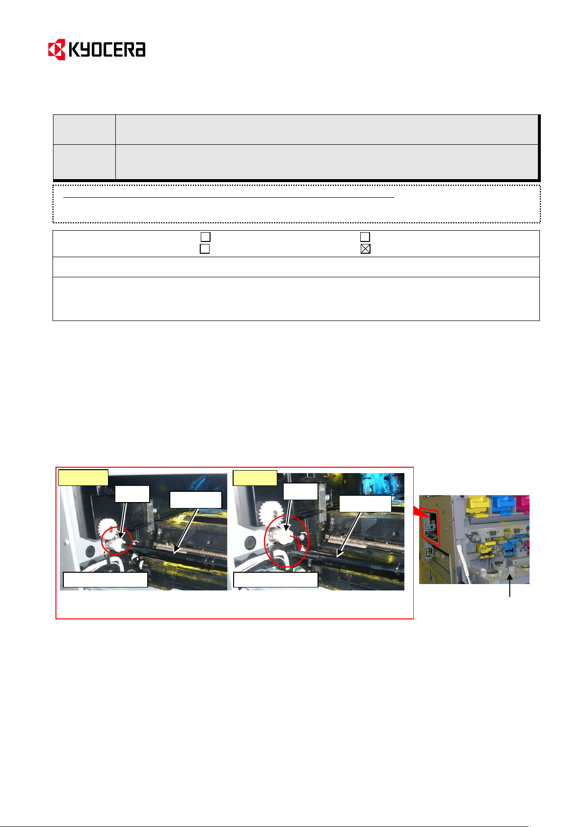
Correct
Wrong
The shaft (X) is inserted in the (-->)
joint of the drive unit.
Machine rear side
The shaft (X) comes off from the (-->)
joint of the drive unit.
Shaft (X)
Retainer section
Joint
Joint
Shaft (X)
Machine rear side
Service Bulletin Ref. No. 2MV-0013 (D069)
[Service Information] <Date> July 2, 2013
This time, the description with (-->) was revised from the previous information.
<Number of changes: 9> The part name was corrected from cam to joint.
The permanent measures were added to the pages 3 and 4.
[Notes]
When refitting the drive unit, please make sure to insert the following shaft (X in the figure) into the (-->)
joint of the drive unit, and then fix the drive unit.
Afterwards, please check if the (-->) joint (X) is inserted in the gear on the machine front side.
[Phenomenon when the shaft (X) comes off]
If the shaft (X) comes off, some abnormal noise from the intermediate transfer unit might be recognized or toner
might leak from the retainer section. (Please refer to the next page for more details on the mechanism.)
KYOCERA Document Solutions Europe
Customer Services & Support Division (CSSD)
Page 2
(Revised Issue 1) (Page.2/5)
1
2
3
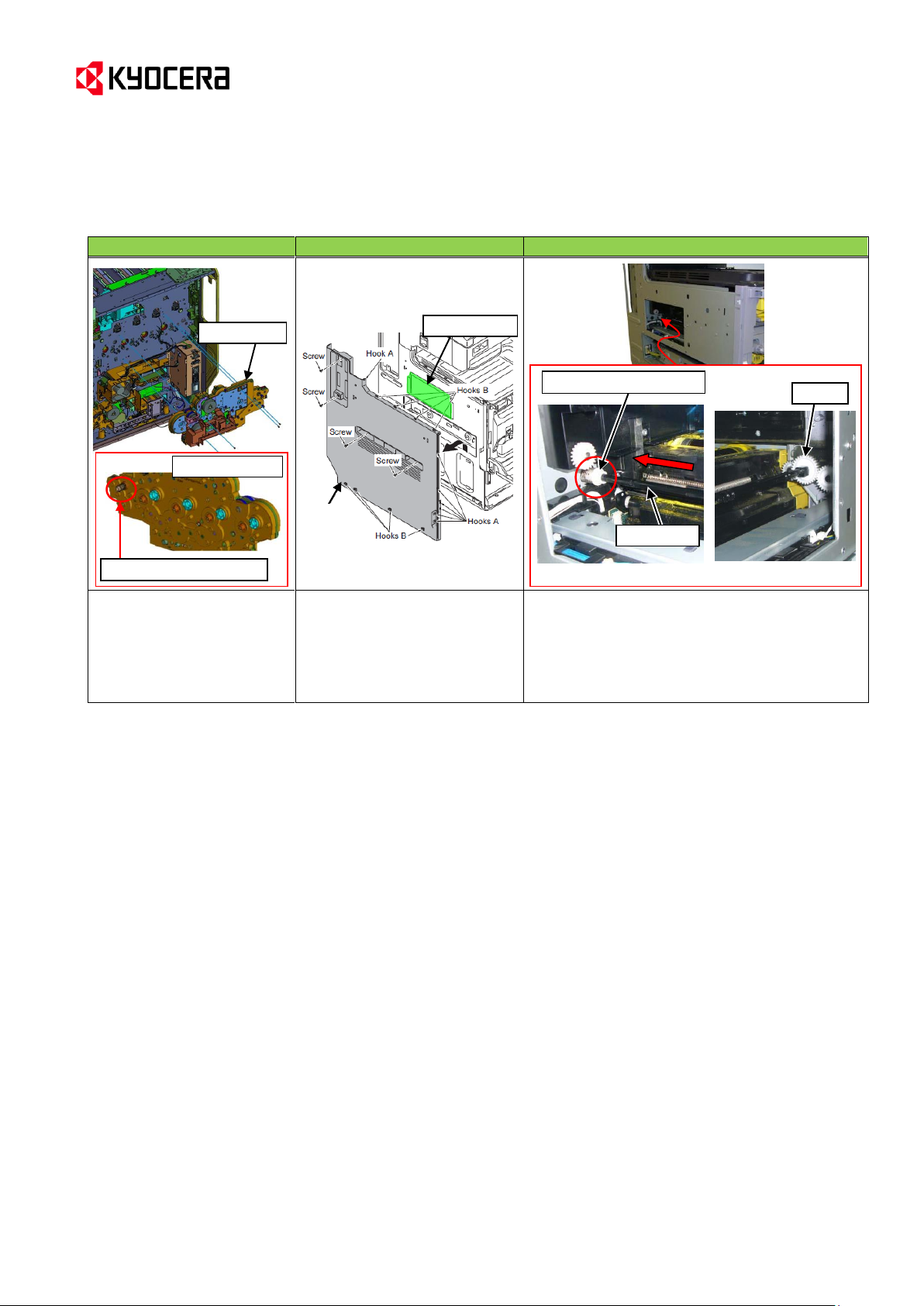
Refit the drive unit (*).
* DR-895 (302K09312_)
Remove the left lower cover, the
main PWB and the intermediate
transfer unit to insert the shaft (X)
into the (-->) joint of the drive unit
from the aperture of the metal plate
behind the main PWB.
Insert the shaft (X) into the (-->) joint of the drive
unit.
(Note) At this time, check if the front end of the shaft
(X) is inserted in the gear on the machine
front side.
Machine inside
Joint part with the shaft
Cam of the drive unit
Shaft (X)
(Machine front side)
(Machine rear side)
Gear
Drive unit
Left
lower
cover
Main PWB
Service Bulletin Ref. No. 2MV-0013 (D069)
[Service Information] <Date> July 2, 2013
[Procedures how to refit the drive unit]
<Mechanism of the phenomenon when the shaft (X) comes off>
1) The spiral (A) to convey the waste toner collected from the intermediate transfer unit to the retainer section
does not rotate. Therefore, waste toner accumulates in the cleaning screw section inside of the intermediate
transfer unit. As a result, some abnormal noise might be generated by skipping of the teeth of the machine
side gear to drive the cleaning screw.
2) The drive transmission part (B) to the spiral inside of the retainer section does not drive. Therefore, the spiral
is not rorated to convery the waste toner collected from the intermediate transfer unit and the drum unit to the
waste toner bottle. As a result, the waste toner excessively accumulated inside of the retainer section might
leak.
Customer Services & Support Division (CSSD)
KYOCERA Document Solutions Europe
Page 3

(Revised Issue 1) (Page.3/5)
Gear skipping the teeth
(Driven by the machine side)
Shaft (X)
Drive unit
Cleaning screw
To retainer section
Drive transmission section (B) to
the spiral inside the retainer section
B
B’
The spiral inside of the retainer
section is rotated by the drive
transmitted from B to B’.
Spiral (A) transfering
the waste toner to the
retainer section
Spiral inside the
retainer section
- The shaft (X) transmits the drive to A and B in the figure above.
- The red arrow ( ) in the figure above indicates the flowing direction of the waste toner.
Service Bulletin Ref. No. 2MV-0013 (D069)
[Service Information] <Date> July 2, 2013
KYOCERA Document Solutions Europe
Customer Services & Support Division (CSSD)
Page 4

(Revised Issue 1) (Page.4/5)
No.
Old Part
No.
New Part
No.
Description
Q’
ty
Com
bi
patility
Remarks
Old
New
Old
New
1
302K031710
2K031710
302MV21110
2MV21110
SHAFT TRANSFER CLEANING
DRIVE
1
1
O
O
(Old)
(New)
Ribs added to
BASE TERMINAL
Shape change of the
shaft (No.1)
Drive unit
Joint
Shaft (No.1)
Rear frame
Front frame
<Shape change of the shaft (No.1)>
BASE TERMINAL
Shape changed
Ribs added
<Shape change of the BASE TERMINAL
(Not supplied)>
<Cross section>
The shaft will not fall off by being held by the ribs
of the BASE TERMINAL when detaching the drive
unit.
BASE TERMINAL
(Old)
(New)
(Machine left side)
BASE TERMINAL
No.1
No.1
Service Bulletin Ref. No. 2MV-0013 (D069)
[Service Information] <Date> July 2, 2013
(-->)
Permanent measures
The shape of the shaft (No.1) and the BASE TERMINAL (Not supplied) was changed so that the shaft removed
from the joint of the drive unit will not fall off when detaching the drive unit and the shaft can be smoothly inserted
into the joint of the drive unit when reattaching the drive unit.
Customer Services & Support Division (CSSD)
KYOCERA Document Solutions Europe
Page 5

(Revised Issue 1) (Page.5/5)
KDE
1102MV3NL0
NUZ3714494
KDE
1102MZ3NL0
NXE3703694
KDE
1102MY3NL0
NXA3702191
Service Bulletin Ref. No. 2MV-0013 (D069)
[Service Information] <Date> July 2, 2013
Serial Nos. of the Affected Machines
<Shape change of the base terminal (not supplied)>
TASKalfa 2550ci
TASKalfa 206ci
TASKalfa 256ci
KYOCERA Document Solutions Europe
Customer Services & Support Division (CSSD)
 Loading...