

Page 1
PRESCRIBE Commands
Technical Reference
Page 2

Page 3

Notice
General Infomation
We shall have no liability or responsibility to customers or any other person or entity with respect to any liability, loss or
damage caused or alleged to be caused directly or indirectly by equipment sold or furnishe d by us, inc luding, but not limited
to, any interruption of service, loss of business or anticipatory profits, or consequential damages resulting from the use or
operation of the equipment or software.
NO LIABILITY WILL BE ASSUMED FOR ANY DAMAGE CAUSED BY IMPROPER INSTALLATION.
Notice on Software
SOFTWARE USED WITH THIS PRINTING SYSTEM MUST SUPPORT IT’S NATIVE MODE (PR ESCRIBE) OR ONE OF
ITS EMULATION MODES.
This manual, the computer programs in the printing system referred to in this manual, and any other copyrightable subject
matter sold or provided with or in connection with the sale of the printing system, are protected by copyright. All rights are
reserved. Copying or other reproduction of all or part of this manual, the computer programs, or any other copyrightable
subject matter without the prior written consent of Kyocera Mita Corporation is prohibited. Any cop ies made of all or part of
this manual, the computer programs, or any other copyrightable subject must contain the same copyright notice as the
material from which the copying is done.
The information in this manual is subject to ch ange wit hout no tificat ion. Addit ional pages may be inserted in f uture ed itions.
The user is asked to excuse any omissions or errors in the present edition.
No responsibility is assumed if accidents occur while the user is following the instructions in this manual. No responsibility
is assumed for defects in the printing system’s firmware.
Regarding Tradenames
PRESCRIBE is a registered trademark of Kyocera Corporation. KPDL is a trademark of Kyocera Corporation.
Diablo 630 is a product of Xerox Corpo ra tion. IBM Proprinter X-2 4E is a product of Internat ional B usines s Machines C orp o-
ration. Epson LQ-850 is a product of Seiko Epson Corporation. HP LaserJet, Hewlett-Packard, PCL, and HP-GL/2 are registered trademarks of Hewlett-Packard Company. Other product names and company names that appear in this manual
are trademarks or registered trademarks of their respective owners.
The Kyocera printing systems use PeerlessPrint5 to provide the HP LaserJet compatible PCL5 language emulation.
PeerlessPrint5 is a trademark of The Peerless Group, Redondo Beach, CA 90278, U.S.A.
© Copyright 2005 KYOCERA MITA Corporation
All rights reserved
Revision 4.2 2005.1
Typeface Trademark Acknowledgement
All resident fonts in the printing system are licensed from Bitstream Inc. and Agfa corporation. For font license information
for each model, refer to the User’s Manual.
Helvetica, Palatino and Times are registered trademarks of Linotype-Hell AG. Century Schoolbook, Stymie, and CooperBlack are trademarks of Kingsley-ATF Type Corporation. ITC Avant Garde Gothic, ITC ZapfChancery, ITC ZapfDingbats,
ITC Souvenir, ITC Benguiat, and ITC Bookman are registered trademarks of International Typeface Corporation. Revue is
a trademark of Esselte Pendaflex Corporation in the U.S., Letraset Canada Ltd. in Canada, and Esselte Letraset Ltd. elsewhere.
Agfa Japan License Agreement Guidelines for the Resident Fonts
1. Software shall mean the digitally encoded, machine readable, scalable outline data as encoded in a s pecial f ormat as
well as the UFST Software.
2. You agree to accept a no n-exclusive license to us e the Software to re produce and display weight s, styles and versions
of letters, numerals, characters and symbols (“Typefaces”) solely for your own customary business or personal purposes at the address stated on the registration card you return to Agfa Japan. Under the terms of this License Agreement, you have the right to use the Fonts on up to three printing systems. If you need to have access to the fonts on
i
Page 4

more than three printing systems, you need to acquire a multi-user license agreement which can be obtained from
Agfa Japan. Agfa Japan retains all rights, titl e and int erest t o the Sof tware and Typefaces and no rights are grant ed to
you other than a License to use the Software on the terms expressly set forth in this Agree m ent.
3. To protect proprietary rights of Agfa Japan, you agree to maintain the Software and other proprietary information concerning the Typeface s in strict confide nce and to establish re asonable proced ures regulat ing access to and use of the
Software and Typefaces.
4. You agree not to d uplicate or copy the Sof tware or Typefaces, except that you ma y make on e backup co py. You agree
that any such copy shall contain the same proprietary notices as those appearing on the original.
5. This License shall continue until the last use of the Software and Typefaces, unless sooner terminated. This License
may be terminated by Agfa Japan if you fail to comply with the terms of this License and such failure is not remedied
within thirty (30) days after notice from Agfa Japan. When this Licen se expire s or is t erminate d, you s hall eithe r return
to Agfa Japan or destroy all copies of the Software and Typefaces and documentation as requested.
6. You agree that you will not modify, alter, disassemble, decrypt, reverse engineer or decompile the Software.
7. Agfa Japan warrants that for ninety (90) days after delivery, the Software will perform in accord ance with Agfa Japanpublished specifications, and the diskette will be free from defects in material and workmanship. Agfa Japan does not
warrant that the Software is free from all bugs, errors and omissions.
THE PARTIES AGREE THAT ALL OTHER WARRANTIES, EXPRESSED OR IMPLIED, INCLUDING WARRANTIES
OF FITNESS FOR A PARTICULAR PURPOSE AND MERCHANTABILITY, ARE EXCLUDED.
8. Your ex clusive remedy and the sole liability of Agfa Japan in connection with the Software and Typefaces is repair or
replacement of defective parts, upon their return to Agfa Japan.
IN NO EVENT WILL AGFA JAPAN BE LIABLE FOR LOST PROFITS, LOST DATA, OR ANY OTHER INCIDENTAL
OR CONSEQUENTIAL DAMAGES, OR ANY DAMAGES CAUSED BY ABUSE OR MISAPPLICATION OF THE
SOFTWARE AND TYPEFACES.
9. New York, U.S.A. law governs this Agreement.
10. You shall not sublicense, sell, le ase, or othe rwise tr ansfer the Software and/ or Typefaces without the prior written consent of Agfa Japan.
11. Use, duplication or disclosure by the Government is subject to restrictions as set forth in the Rights in Technical Data
and Computer Software clause at FAR 252-227-7013, subdivision (b)(3)(ii) or subparagraph (c)(1)(ii), as appropriate.
Further use, duplication or disclosure is subject to restrictions applicable to restricted rights software as set forth in
FAR 52.227-19 (c)(2).
12. YOU ACKNOWLEDGE THAT YOU HAVE READ THIS AGREEMENT, UNDERSTAND IT, AND AGREE TO BE
BOUND BY ITS TERMS AND CONDITIONS. NEITHER PARTY SHALL BE BOUND BY ANY STATEMENT OR REPRESENTATION NOT CONTAINED IN THIS AGREEMENT. NO CHANGE IN THIS AGREEMENT IS EFFECTIVE
UNLESS WRITTEN AND SIGNED BY PROPERLY AUTHORIZED REPRESENTATIVES OF EACH PARTY. BY
OPENING THIS DISKETTE PACKAGE, YOU AGREE T O ACCEPT THE TERMS AND CONDITIONS OF THIS
AGREEMENT.
ii
Page 5

Introduction
This manual contains information needed to use the firmware features provided by the
Kyocera printing system. Among these features is PRESCRIBE, a highly accessible,
human-readable command language that makes it easy for programmers to take full
advantage of the printing system’s capability.
The PRESCRIBE command language allows to:
• extensive manipulation of fonts and character code tables
• use the ability to draw objects by constructing and manipulating paths including
ellipses and round boxes, etc.
• execute macros including carbon-copy macro
• control external optional units (feeders, etc.)
You can access the features of PRESCRIBE from any of the seven emulation modes.
These modes include:
• Hewlett-Packard LaserJet emulation
• Hewlett-Packard HP 7550A (plotter) emulation
• IBM Proprinter X24E (24-pin dot matrix printer) emulation
• Epson LQ-850 (24-pin dot matrix printer) emulation
• Diablo 630 emulation
• generic line printer emulation
• KPDL (Apple LaserWriter II NTX (NT) emulation) [an option on some models]
iii
Page 6

About the Technical Reference manual
The Technical Reference manual is or ganized into eight chapters. The first four chapters
of this manual constitute an tutorial introduction to PRESCRIBE. The rests mainly concern advanced utilities and setups:
Chapter 1 Introduction to PRESCRIBE introduces some basic concepts of PRESCRIBE.
Chapter 2 Graphics Tutorial outlines the graphic handling features of PRESCRIBE.
Chapter 3 Macros introduces program macros, a concept that makes it easy to define
sequences of PRESCRIBE commands, then call them repeatedly whenever they are
needed.
Chapter 4 Fonts provides how to manage font selection and font samples.
Later, Chapter 5 Barcodes explains the barcode printing capabilities of the command
language.
Chapter 6 Permanent Parameters explains how to reprogram the printing system’s firm-
ware for customization.
Chapter 7 Emulation gives notes on the printing system’s various emulation modes.
An Index is also provided at the end of this manual.
Notice
Most PRESCRIBE commands operate in the same way on all of these models. However,
on particular models, some commands are irrelevant. Model-dependent differences are
noted at the pertinent locations in this manu a l .
Conventions
• italic is used for emphasis and also refers to a related chapter or section in this man-
• fixed-pitch means text or commands that you must type exactly as it appears.
ual or another related document.
iv
Page 7

Table of Contents
General Infomation...................................................................................................................................i
Introduction.............................................................................................................................................iii
Introduction to PRESCRIBE
Format of PRESCRIBE Commands ....................................................................................................1-4
Basic Concepts......................................................................................................................................1-4
Edge Limits ..................................................................................................................................1-4
Margins ........................................................................................................................................1-4
Page Orientation and Direction ....................................................................................................1-5
Coordinate Systems ............................................................... ......................................................1-7
Text Positioning ...........................................................................................................................1-7
Character Spacing ........................................................................................................................1-8
Paths .............................................................................................................................................1-9
Logical Page and Physical Page ..................................................................................................1-9
Command Parameters.........................................................................................................................1-10
Numeric Parameters ...................................................................................................................1-10
Character Strings ........................................................................................................................1-11
Upper and Lowercase Letters .....................................................................................................1-12
Special Parameters .....................................................................................................................1-13
Graphics Tutorial
Drawing Lines ..............................................................................................................................2-2
Drawing Boxes and Circles .............................. ................................................................... .........2-6
Drawing Filled Shapes..................................................................................................................2-9
Path Mode Graphics............................................................................................................................2-16
Path ............................................................................................................................................2-16
Drawing Lines.............................................................................................................................2-18
Miter Limit .............................................................................................. ...................................2-21
Drawing Arcs and Curves ............................................................................. .............................2-24
Drawing Complex Curves ..........................................................................................................2-26
Closed Paths ...............................................................................................................................2-29
Filled Areas ................................................................................................................................2-30
Clipping Rectangle .................................................................... .................................................2-32
Printing with Character Paths ....................................................................................................2-33
Raster Graphics ..................................................................................................................................2-34
Raster Data Compression Formats .............................................................................................2-34
Commands for Printing Raster Data ..........................................................................................2-35
Printing Raster Data....................................................................................................................2-37
Changing the Printing System’s Imaging Model .......................................................................2-37
Saving and Restoring the Graphics State ...................................................................................2-39
Macros
Examples of Macros .............................................................................................................................3-3
Fonts
List of Fonts............................ .................................. ....................................................................4-2
KPDL Fonts..................................................................................................................................4-4
Substituting a Bitmap Font ..........................................................................................................4-6
v
Page 8

Font Selection.......................................................................................................................................4-7
Font Selection by PRESCRIBE Commands ...............................................................................4-7
Placement of Font Commands ...................................................................................................4-11
Creation of New Symbols and Characters .........................................................................................4-12
Symbol Set..........................................................................................................................................4-13
International Characters.............................................................................. ................................4-14
Selecting HP Symbol Sets..........................................................................................................4-14
Barcodes
PDF417 Symbol Description......................................................................................................5-10
Printing a Two-dimensional Barcode.........................................................................................5-12
Limitations of Two-dimensional Barcode..................................................................................5-13
Macro PDF417 ...........................................................................................................................5-14
Creating a Macro PDF 417 Representation ................................................................................5-14
Permanent Parameters
Interface-dependent Parameters ...................................................................................................6-2
Interface-independent Parameters ................................................................................................6-5
Emulation
Automatic emulation sensing ..................................................... ................................. .................7-3
General Information on Emulation ..............................................................................................7-3
Line Printer Emulation (Mode 0) ........................................................................................................7-3
IBM Proprinter X24E Emulation (Mode 1) ........................................................................................7-4
IBM Proprinter X24E Control Codes...........................................................................................7-6
Diablo 630 Emulation (Mode 2) ........................................................................................................7-12
Diablo 630 Control Codes .........................................................................................................7-14
LaserJet Fonts.............................................................................................................................7-35
LaserJet Symbol Sets..................................................................................................................7-37
Resource Protection....................................................................................................................7-40
Switching the Print Resolution...................................................................................................7-42
HP LaserJet Reset State..............................................................................................................7-43
LaserJet PJL................................................................................................................................7-43
PJL Syntax Comparison .............................................................................................................7-66
Basic ...........................................................................................................................................7-96
KC-GL Environment Options ....................................................................................................7-97
Plotter Status Information ................................................................................ ........................7-102
Device-Control Instructions .............................................................. ......................................7-106
Fonts and Symbol Sets in KC-GL............................................................................................7-107
Summary of KC-GL Instructions ............................................................................................7-111
Communication with the Printing System................................................................................7-115
KPDL Summary.......................................................................................................................7-116
KPDL Error Messages..............................................................................................................7-139
KPDL Printable Area................................................................................................................7-140
Index
vi
Page 9

Chapter 1
Introduction to PRESCRIBE
PRESCRIBE is the native language of the Kyocera printing systems including copiers
(collectively referred to as printing systems hereafter). Consisting of easily remembered
commands, such as ‘SLM’ for Set Left Margin, and ‘BOX’ to draw a box, it gives you
the capability to control line and character spacing, adjust margins, change fonts, position text, draw graphics, and print multiple copies of each page. PRESCRIBE also gives
freedom to control device settings including selection of paper source, output stack, and
finishing operations such as sorting, stapling, etc.
Most application software controls printing systems by means of codes and escape
sequences that are built into the program and are not directly visible to the user. In contrast, PRESCRIBE commands are made of ordinary characters that you can type in yourself and see on the computer screen. This makes it easy for you to customize printing and
add features that may not be supported by your application.
This chapter presents an introduction to PRESCRIBE starting with an explanation of the
commands by which you start and exit PRESCRIBE. It is followed by an introduction to
some basic concepts of PRESCRIBE, then a discussion of the command format and
command parameters.
Page 10
Chapter 1 Introduction to PRESCRIBE
Entry and Exit
The printing system can be thought of as having a multiple personality. When its power
is switched on, it performs the normal printing system functions of printing out files and
other data. Application software can control the printing system using one of the seven
emulations. When the printing system uses an emulation, it is said to be printing in emulation mode.
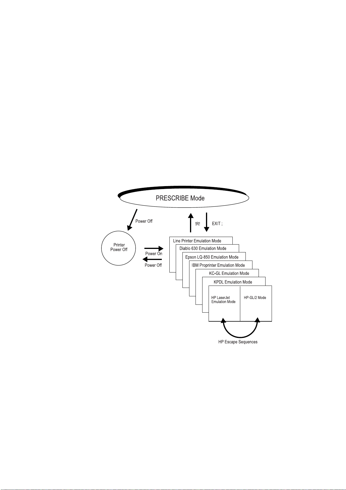
PRESCRIBE is an additional mode of operation in which the printing system understands data it receives not as text to be printed, but as commands to be executed. The
PRESCRIBE mode is available at any time during operation from any emulation mode.
The initializing string that takes the printing system from the usual text-printing mo de
into the PRESCRIBE mode is !R!. The command that returns it from the PRESCRIBE
mode to the emulation mode is EXIT;. These transitions are diagramed in the figure
below.
Figure 1. 1. Mode Transitions
1-2
The printing system’s emulation mode can be permanently set by the FRPO (Firmware
RePrOgram) P1 command. See Chapter 7 for details. The printing system is factory-set
to emulate the Hewlett-Packard LaserJet.
The example below shows how these transitions can be used in a file. The lines beginning with !R! are PRESCRIBE commands. Note how each block of commands begins
with !R! and ends with EXIT;. These sections are not printed; instead, they set margins,
select three different fonts, and draw a box around one line of text. The remainder of the
file consists of ordinary text, and is printed out as shown in the figure on the next page.
Page 11
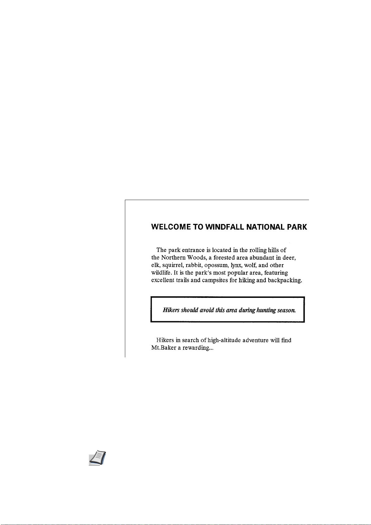
Figure 1. 2. Text Including PRESCRIBE Commands
!R! RES; SLM 1; STM 1; SPD 0.03; FTMD 13;
SFNT "Helvetica-Bd"; EXIT;
WELCOME TO WINDFALL NATIONAL PARK
!R! SFNT "Times-Rom"; EXIT;
The park entrance is located in the rolling hills of
the Northern Woods, a forested area abundant in deer,
elk, squirrel, rabbit, opossum, lynx, wolf, and other
wildlife. It is the park’s most popular area, featuring
excellent trails and campsites for hiking and backpacking.
!R! BOX 3.4, 0.55; FSET 1s5B; EXIT;
Hikers should avoid this area during hunting season.
!R! SFNT "Times-Rom"; EXIT;
Hikers in search of high-altitude adventure will find
Mt.Baker a rewarding...
Figure 1. 3. PRESCRIBE Example
Note
The previous example contains five sequences of PRESCRIBE commands. The basic
configuration of a PRESCRIBE command sequence is:
!R! command; command; ...; command; EXIT;
There is a limit to the number of commands you can include between the initial !R! and
the final EXIT;. The initial !R! must be followed by a space, and each command must
end with a semicolon.
The use of PRESCRIBE commands in document files is conditional on the behavior of your
word processing software. Some word processing programs add control codes that interfere with PRESCRIBE. If you cannot control software in this way, try using a non-word processing mode (ASCII text function, for example) of the software.
1-3
Page 12

Chapter 1 Introduction to PRESCRIBE
Format of PRESCRIBE Commands
The basic format of a PRESCRIBE command is:
• • • or • • • • (command name) parameter, ..., parameter;
The command names generally consist of three or four letters. In most commands, the
parameters must be followed by commas. The last parameter is always followed by a
semicolon. Some commands (RES, for example) have no parameters. In this case, the
command should be followed immediately by a semicolon (RES;).
The length of a single PRESCRIBE command is limited to 255 characters, from the first
letter of the command name through the final semicolon. Commands longer than 255
characters are not executed.
Spaces, carriage return codes, and line feed codes are generally ignored in PRESCRIBE
command sequences. These characters are not generally counted in the command length.
(Exception: Spaces are not ignored in quoted character strings.) To improve readability,
place at least one space before each command or place each command on a separate line.
Basic Concepts
This section discusses a few basic concepts concerning how the printing system prints on
the page. These concepts are:
• Edge limits
• Margins
• Coordinate systems
• Text positioning/Character spacing
•Paths
• Logical page and physical page
• Page orientation and direction
Edge Limits
The printing system cannot place print on the outside edges of the paper. The edge limits
to which printing is possible are located 5 mm inside the edges of the paper; or 6 mm
(5mm in landscape orientation) from the left edge and 4 mm from the top of the paper in
HP LaserJet emulation. Refer to the figure Edge Limits and Margins on page 5.
The edge limits adjust automatically to the size of the paper cassette (although not to the
size of manually fed paper). The edge limits can also be set to various standard sizes by
the SPSZ (set paper size) command, or by the equivalent HP LaserJet commands. In HP
LaserJet emulation, the edge limits slightly vary according to the page orientation (as
also shown in Edge Limits and Margins on page 5).
1-4
Margins
The top and left margins are set in centimeters or inches in relation to the top and left
edge limits of the page. The bottom and right margins can also be set as a distance from
the top and left edge limits, or they can be set in terms of page width, page length, or
lines per page.
Page 13
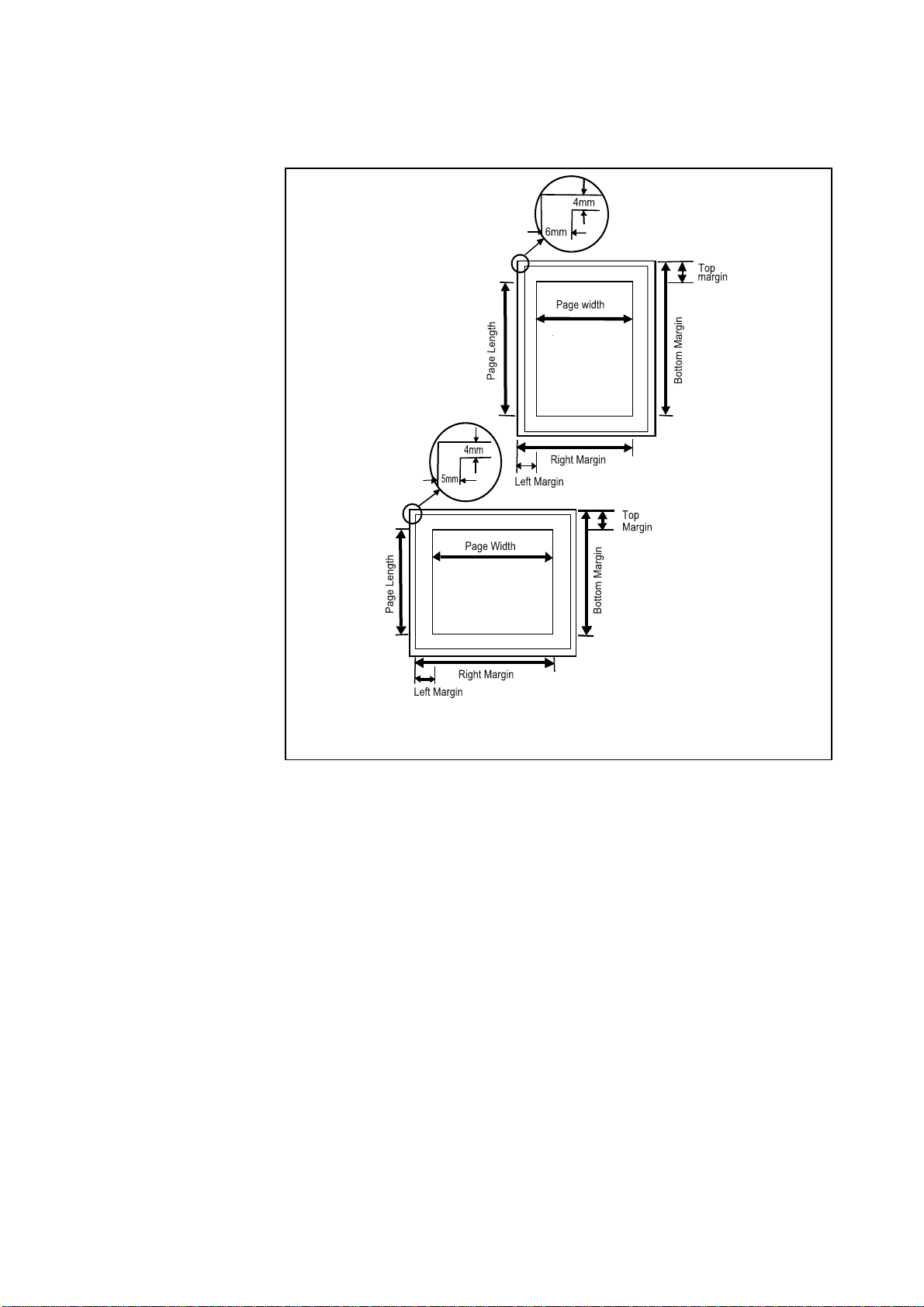
Figure 1. 4. Edge Limits and Margins
Portrait Orientation
Edge limits in HP emulation
Basic Concepts
Edge limits in HP emulation
When the printing system passes the bottom margin while printing text, it prints the page
and feeds to the next page. Spacing is carried over, so if the bottom margin does not
occur at an exact number of lines, excess space is printed at the top of the next page.
If you are using word-processing software that sets the margins automatically, you
should not set them with PRESCRIBE commands.
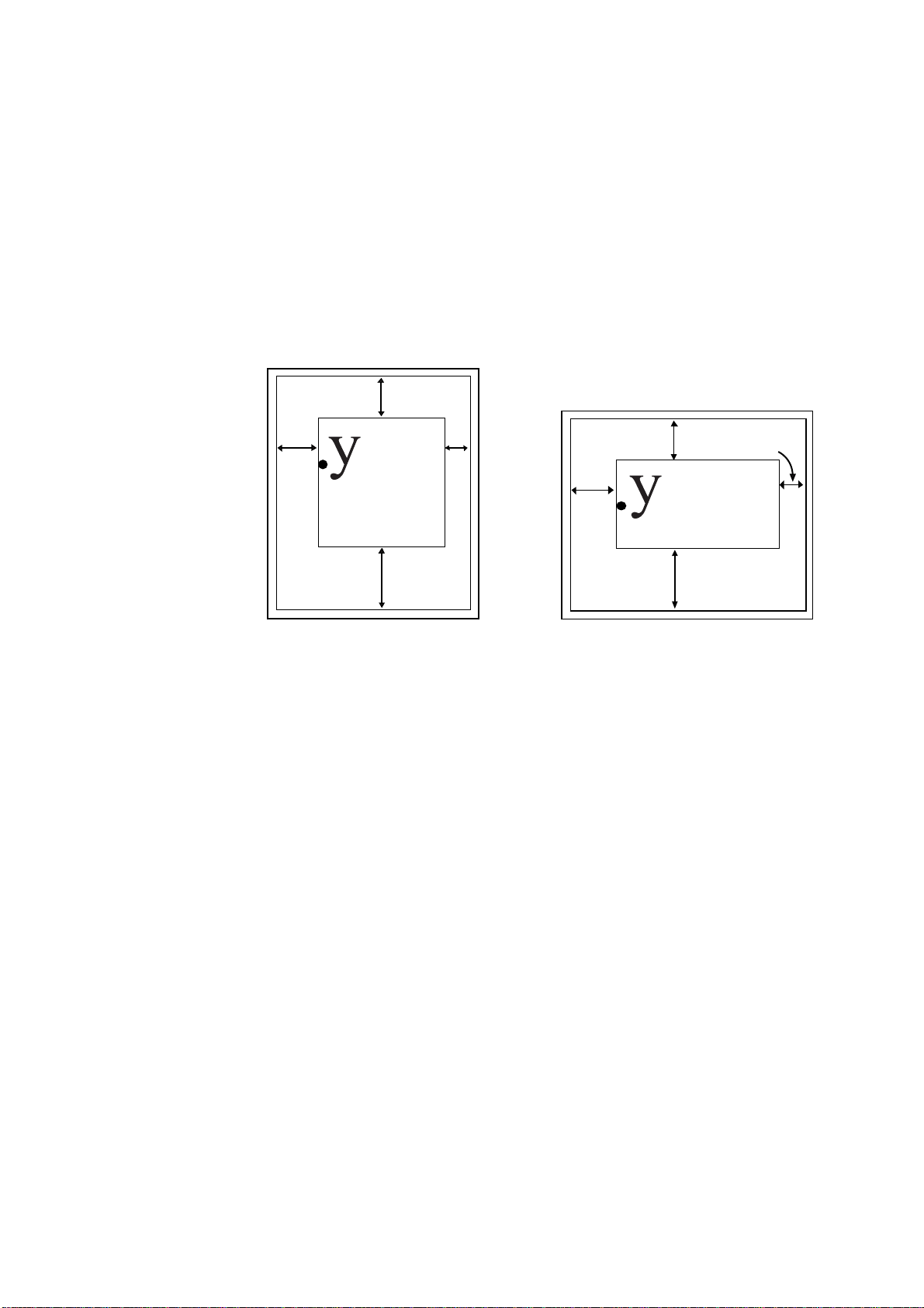
Page Orientation and Direction
The term page orientation refers to the direction in which text is placed on the page. In a
vertical direction, it would be called portrait and a horizontal direction would be called
landscape. The term print direction, which follows this section, refers to the orientation
of the logical page’s coordinate system with respect to the current page orientation.
Landscape orientation
1-5
Page 14
Chapter 1 Introduction to PRESCRIBE
Portrait Orientati
Page Orientation
Changing the page orientation automatically adjusts the margins so that they remain the
same distance from the four edges of the paper. If the printing system cannot make these
margin settings (for example, if the left margin would be to the right of the right margin),
it sets the margins to the edge limits.
Fonts are automatically rotated to match the current orientation.
Figure 1. 5. Page Orientations
on
Top
margin
Left
margin
Print Direction
The print direction can be modified in 90° increments. These page orientations are
referred to as portrait, landscape, reverse portrait, and reverse landscape. Changing the
print direction rotates the page coordinate system in the same manner as changing the
page orientation. However, in this case, portrait refers to the print direction in which the
axes of the coordinate system are oriented in the same direction as for the currently
selected page orientation.
Changing the print direction also changes the margins to maintain the same printable
area as prior to the change. The current position (the physical location in which the next
character will be printed) and its coordinate va lues rem ain the same as in the previo us
print direction.
Bottom
margin
Right
margin
Left
margin
Bottom
margin
Right
margin
1-6
Changing the print direction also changes the orientation of any subsequent raster graphics and PRESCRIBE vector graphics. However, it does not affect the orientation of any
subsequent HP-GL/2 graphics. (HP-GL/2 graphics can only be rotated with the HP-GL/2
RO command or the LaserJet orientation command.)
Page 15
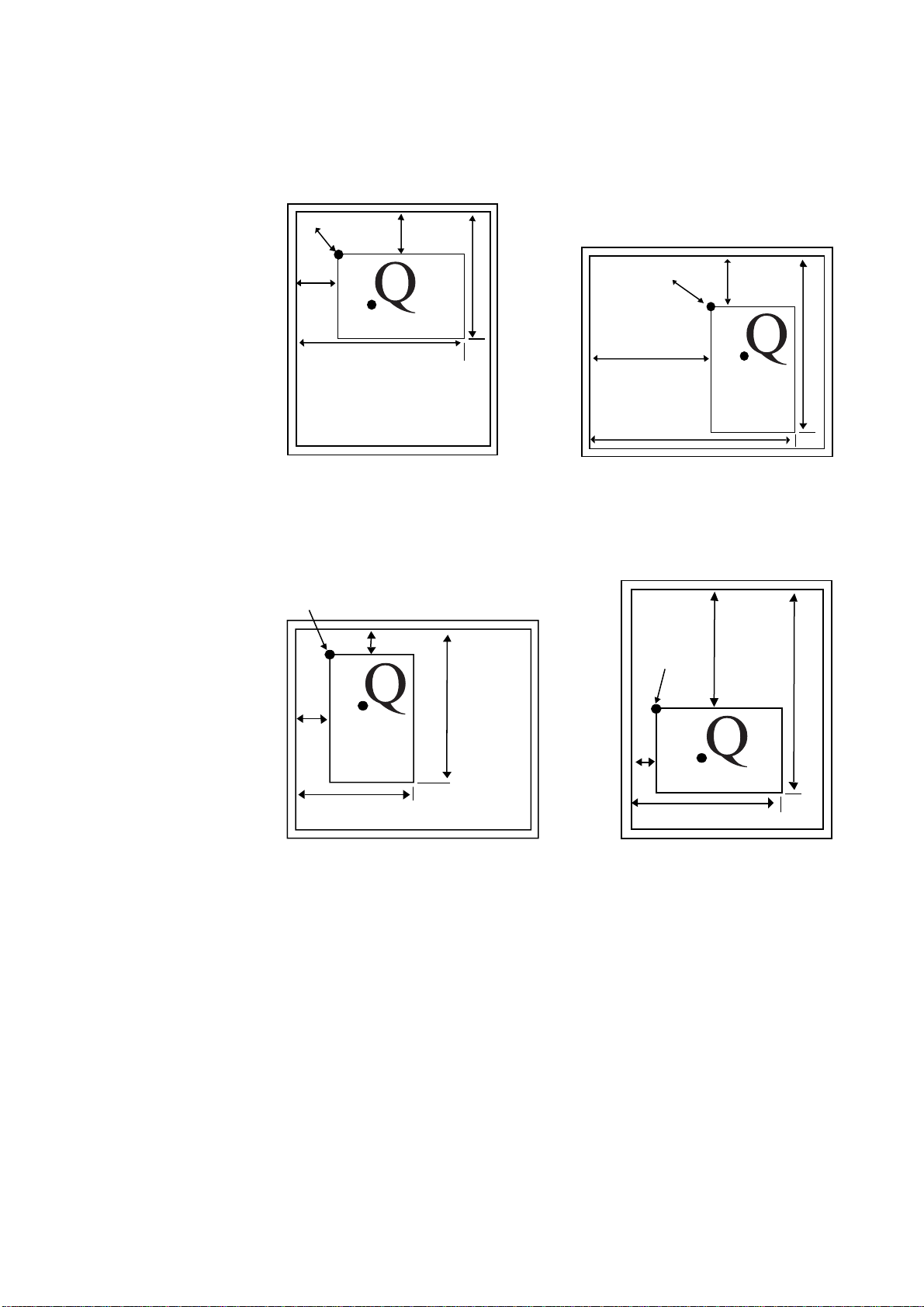
Figure 1. 6. Print Direction
Portrait print direction
Basic Concepts
Current Point
Left
margin
Right margin
Reverse portrait print direction
Current point
Top
margin
Top margin
Bottom margin
Landscape print direction
Current Point
Left margin
Right margin
Reverse landscape print direction
Current point
Top
margin
Bottom margin
Top margin
margin
Left
Right margin
Coordinate Systems
With PRESCRIBE, posit i ons on a page are described in terms of X and Y coordinates.
The origin of the coordinate system (the position at which X and Y both equal 0) is
located at the intersection of the top margin and the left margin. Values of X greater than
0 indicate positions to the right of the origin, and values of Y indicate positions below the
origin. See the figure on page 10. When the top and left margins are changed, the physical position of the origin changes accordingly.
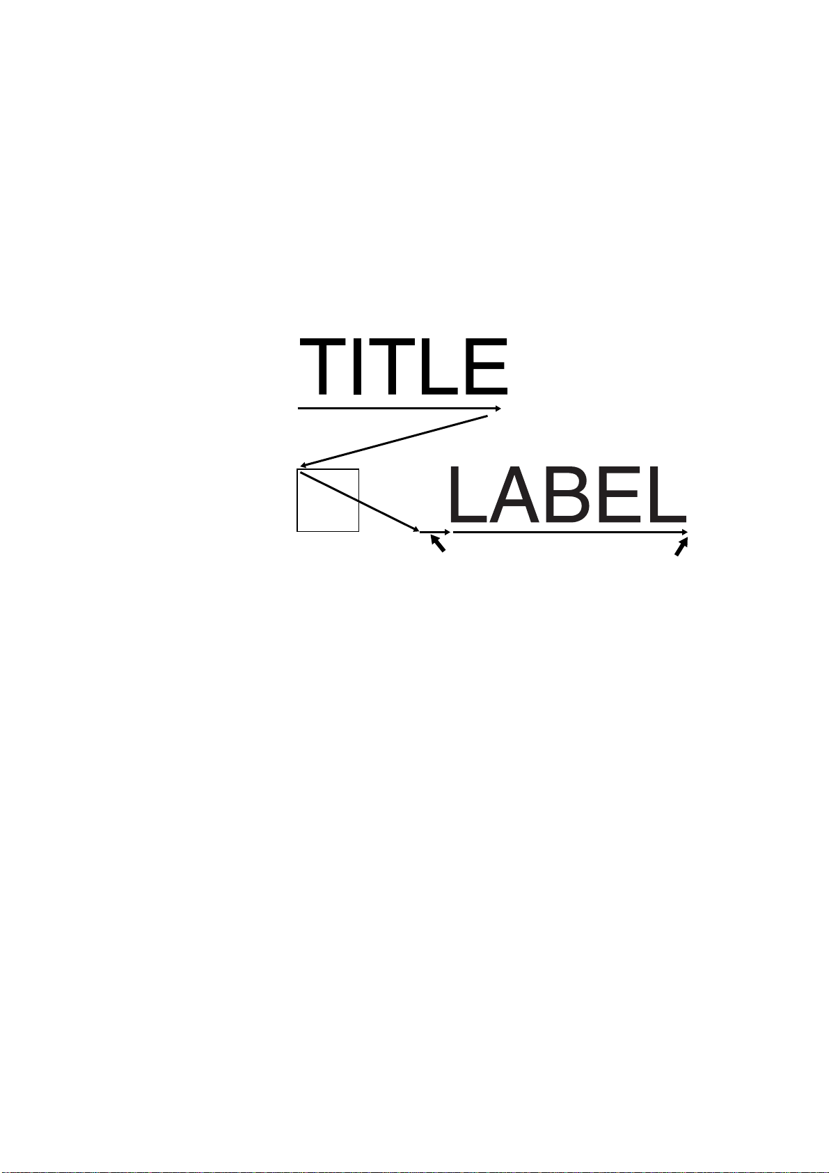
Text Positioning
Bottom margin
Bottom margin
Left margin
Right margin
The printing system always keeps track of its current position on the page. The current
position can be thought of as a cursor that moves as data is printed. At any instant, the
1-7
Page 16
Chapter 1 Introduction to PRESCRIBE
cursor indicates where the next character will be printed or the next graphics will be
drawn. (The printing system does not have separate cursors for text and graphics.)
T ex t an d grap hics c an b e po si tio ned at ar bit rary locat io ns on th e page by m ovi ng t he cu rsor with positioning commands (MAP, for example).
Figure 1. 7. Text Positioning
TITLE
!R! BOX 1, 1; MRP 2, 1;
EXIT; LABEL
Landscape Orientation
Carriage Return
BOX 1, 1;
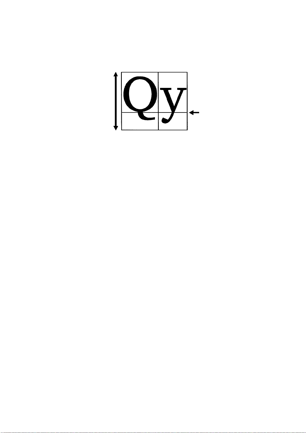
Character Spacing
Each character is printed within an individual cell as shown below. The character sits on
a line called the baseline. Characters such as y descend below the base line.
In some character fonts, all the character cells are the same size, so the number of character positions per inch is fixed. In other fonts, the size of character cells is proportional to
the size of characters. These proportional fonts produce text that is easier to read. However, in order to align the right margin, you must use software that supports the printing
system’s proportional spacing.
MRP 2, 1;
Space after EXIT; Cursor ends here
1-8
Page 17
Paths
Basic Concepts
Figure 1. 8. Character Spacing
Font height
Baseline
A path is a set of straight and curved line segments. Paths can be open, as in the case of
lines, or closed, as in the case of rectangles, circles, or any fully enclosed area of any
shape. The segments may be connected with one another, or they may be disconnected.
Further, a path may contain multiple closed subpaths, representing several areas, and
they may intersect themselves in arbitrary ways.
Paths can be used to draw lines and curves or specify boundaries of filled areas, including the outline of a character.
Paths are explained more fully in section Path Mode Graphics on page 16.
Logical Page and Physical Page
The logical page defines the limits of the coordinates within which text and graphics can
be located. There are two types of logical page, as shown in the following figure. The
standard mode logical page imposes limits on specifiable coordinates. The coordinates
have no limitations for the path mode logical page.
1-9
Page 18
Chapter 1 Introduction to PRESCRIBE
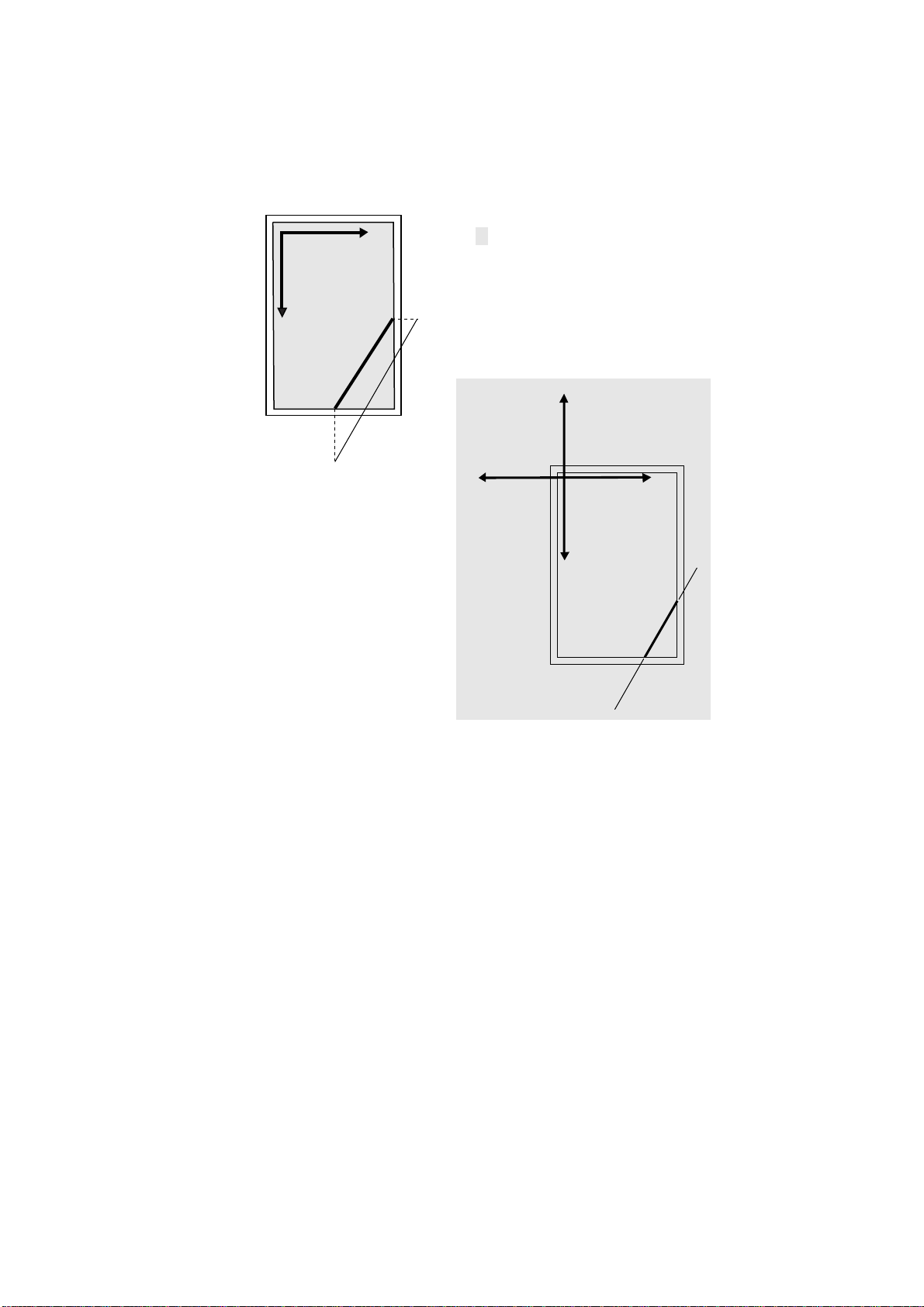
Figure 1. 9. Logical Page and Physical Page
Standard Mode
y
(0,0)
x
= Logical page
Path Mode
−x
−y
x
y
With the standard mode logical page, any position specification that lies outside of the
logical limits is automatically adjusted to bring it within the limits. For example, the
page on the upper left in the preceding figure shows what happens if you attempt to draw
a diagonal line from below the bottom edge limit to a point to the right of the right edge
limit when the standard mode logical page is used. The fine line represents the line as
specified by the user; the thick line shows what is actually drawn by the printing system.
With the path mode logical page, coordinates are not adjusted even if they fall outside of
the edge limits. In this case, as shown in the lower right page in the preceding figure, the
line is defined by the specified starting and ending points, but parts falling outside of the
edge limits are clipped.
Command Parameters
Numeric Parameters
Many of the PRESCRIBE commands use number values to specify parameters. For
example, numbers are used to specify distances in inches, centimeters, points, or dots.
Negative numbers are also allowed.
1-10
Page 19

Command Parameters
For computer code values beyond four decimal places, the fifth and subsequent decimal
places are ignored.
Examples:
Number output by computer Number used by printing system
1234.1234 1234.1234
-1234.1234 -1234.1234
0.123456 0.1234
Some commands have angle parameters. Angles are specified in degrees. (The printing
system does not recognize radians). The printing system rounds off all angles to the nearest integral degree. Only angles in the range from -360 degrees to 360 degrees are recognized. Angles less than -360 degrees are ignored, and angles greater than 360 degrees are
treated as the remainder of the angle divided by 360.
Examples:
Angle output by computer Angle used by printing system (degrees)
90 90
-90 -90
90.4 90
90.5 91
-400 Ignored
The printing system does not accept the exponential notation used in some computer languages. For example, do not specify 1E-3 instead of 0.001.
Character Strings
PRESCRIBE text-printing commands have parameters that consist of character strings.
A character string is any string of characters enclosed by quotation marks or apostrophes,
such as shown in the example below.
TEXT ’You are about to enter PRESCRIBE.’;
PRESCRIBE allows character strings to be enclosed in either single quotation marks
(apostrophes) or double quotation marks. The following example has exactly the same
meaning as the one above.
TEXT "You are about to enter PRESCRIBE.";
The beginning of a character string is recognized when the first single or double quotation mark appears. If the beginning quotation mark is a single quotation mark, the string
does not end until the next single quotation mark. If the beginning quotation mark is a
double quotation mark, the string does not end until the next double quotation mark.
Whatever comes in the middle of a character string, including commas, semicolons, and
even PRESCRIBE command names, is recognized as part of the character string, and not
as part of the PRESCRIBE command language. For example, the expression EXIT; in
the following string is just text; it does not cause the printing system to exit from the
PRESCRIBE mode.
TEXT ’NO EXIT; NO RETURN.’;
When the string itself contains one type of quotation mark, the quotation mark must be
enclosed in quotes of the other type. Here are two examples:
1-11
Page 20

Chapter 1 Introduction to PRESCRIBE
TEXT "You’re about to enter PRESCRIBE.";
TEXT ’ " " " ’;
In the first command above, the character string starts with a double quotation mark. The
printing system therefore expects the string to end with a double quotation mark, and
regards the apostrophe in the word You’re as an ordinary character, not as the string terminator.
Similarly, the double quotation marks in the second command above are recognized as
ordinary characters, not as string terminators.
Since an apostrophe or quotation mark can start a character string anywhere in a PRESCRIBE command sequence, it is important not to start character strings unintentionally.
The following examples demonstrate incorrect use of apostrophes and double quotation
marks.
Incorrect:
!R! CMNT Don’t leave stray apostrophes; EXIT;
Incorrect:
!R! CMNT The symbol " means inches; EXIT;
In both of the above cases, the printing system assumes that the expression EXIT; is part
of a character string started by the preceding apostrophe or quotation mark, and fails to
exit the PRESCRIBE mode. The correct way to write these comments is:
Correct:
!R! CMNT "Don’t leave stray apostrophes"; EXIT;
Correct:
!R! CMNT ’The symbol " means inches’; EXIT;
Character strings must not exceed the 255-character limit on total command length. If a
character string exceeds this limit, the printing system terminates it forcibly and begins
looking for the next PRESCRIBE command.
Upper and Lowercase Letters
Regarding upper and lowercase characters, PRESCRIBE follows the same rule as many
computer programming languages: it discriminates case inside character strings and
ignores it elsewhere. You can type command names in upper or lowercase.
Correct:
!R! TEXT ’A’; CIR 1; EXIT;
1-12
Also correct:
!R! text ’A’; cir 1; exit;
Also correct:
Page 21

Command Parameters
!R! Text ’A’; Cir 1; Exit;
Each of these commands prints the capital letter ‘A’ inside a circle. In the printout shown
above, the unit is centimeters. The reason that the letter ‘A’ is off center in the circle is
that the cursor is not located at the center of the circle, but at left corner of the letter ‘A’.
The command
!R! TEXT ’a’; CIR 1; EXIT;
prints a lowercase a because the letter occurs inside a character string.
The sole exception to upper and lowercase usage in PRESCRIBE commands occurs with
the initializing !R! command. This command must always use an uppercase R. The printing system will not enter the PRESCRIBE mode in response to !r!.
In this manual, PRESCRIBE commands are printed in upper-case for readability.
Outside of PRESCRIBE mode, the printing system always distinguishes between upper-
case and lowercase letters and prints exactly what is sent.
Special Parameters
Some PRESCRIBE commands use unquoted strings of characters as parameters. Examples for these are the FSET (change current font set by characteristic) command and the
CSET (change symbol set by symbol-set ID) command. (See Chapter 4 for a detailed
explanation of how these commands are used to select fonts.)
The FSET and CSET commands use parameters that closely resemble the command
parameters used for font control in Hewlett-Packard’s printer control language. For
example, the PRESCRIBE command
FSET 0p12h12v0s0b6T;
selects the font whose characteristics most closely matches the following font parameters:
• Monospaced font (0p)
• Character spacing of 12 characters/inch (12h)
• Character height of 12 points (12v)
• Upright style (0s)
• Medium weight (0b)
• LetterGothicBM12-Roman typeface (6T)
In Hewlett-Packard’s PCL, the corresponding command would be
ESC(s0p12h12v0s0b6T
1-13
Page 22

Chapter 1 Introduction to PRESCRIBE
Similarly, the PRESCRIBE command CSET 11U; designates use of the PC-8 Danish/Norwegian symbol set. The corresponding Hewlett-Packard PCL command is
ESC(11U.
1-14
Page 23

Chapter 2
Graphics Tutorial
PRESCRIBE provides a wide variety of graphics operators, allowing you to easily construct and print almost any imaginable shape or pattern.
This chapter introduces the various graphics concepts of PRESCRIBE, and illustrates
how to use many of its graphic functions. It defines standard graphics mode, path mode
graphics, and raster graphics. It explains how to use predefined fill patterns, how to
define your own fill patterns, and introduces ways in which you can change the print
model, the rules that determine the manner in wh ich patterns and images are rendered on
the paper.
Page 24

Chapter 2 Graphics Tutorial
Standard Graphics
The standard graphics mode provides a number of operators for constructing a variety of
filled shapes and lines. Using standard mode graphics, you can:
• Draw lines of any desired width
• Draw circles and rectangles
• Draw a variety of filled shapes, including boxes and arcs
• Draw pie charts
This is referred to as the standard graphics mode because it is a standard feature of all
versions of PRESCRIBE.
Drawing Lines
PRESCRIBE provides a number of Draw to commands for drawing lines in both standard and path modes. These include:
DAP (draw to absolute
position)
DZP (draw to zero-relative
position)
DRP (draw to relative position) Draws a line to a position specified as a horizontal and ver-
DRPA (draw to relative
position specified by angle)
Lines to Absolute Position
Begin with a simple task such as drawing a line between two arbitrary points on a page.
Use the MAP and DAP commands to specify positions relative to the top and left margins.
This task has several distinct steps: selecting a line width, determining the starting point
of the line, and determining the end point of the line. The following command sequence
demonstrates this process.
!R! RES;
STM 0.5;
SLM 0.5;
SPD 0.01;
MAP 0.5, 1;
DAP 2, 0.5;
PAGE;
EXIT;
Draws a line to an absolute position in a Cartesian coordinate system whose origin (0,0) is at the intersection of
the left and top margins.
Draws a line to an absolute position in a Cartesian coordinate system whose origin (0,0) is at the intersection of
the left and top edge limits of the paper.
tical displacement from the current cursor position.
Draws a line to a position that is specified as a distance and
angle from the current cursor position. Examples of these
commands are given in the sections that follow.
2-2
Page 25

Figure 2. 1. Result of Draw Commands: Absolute Lines
Edge limits
Margins
DAP 2, 0.5;
MAP 0.5, 1;
The initial !R! command switches the printing system to the PRESCRIBE mode.
Remember that this command must always precede each sequence of PRESCRIBE commands.
The RES (RESet) clears the current page from printing system memory and re-establishes the printing system’s permanent defaults. Although you would not include this
command in every sequence of PRESCRIBE commands, we include it in this example to
ensure consistent results. As a standard practice, include the RES at the beginning and
end of each job.
The STM and SLM set both the top and left margins to 0.5 inches (1.27 centimeters).
The SPD (Set Pen Diameter) command determines the thickness of lines. In the standard
graphics mode, this setting determines the thickness of all lines drawn after the command
is issued. In this example, the line width is set to 0.01 inches.
The starting point of the line is established with the MAP (Move to Absolute Position)
command. This command moves the cursor to a point that is a specified distance from
the top and left margins. In this example, the point specified is 0.5 inches from the left
margin and 1 inch from the top margin.
If the margins are changed, the position specified by MAP also changes correspondingly .
On the next line of the program, the DAP (Draw to Absolute Position) command draws a
line from the starting position to the point 2 inches from the left margin and 0.5 inches
from the top margin.
Finally, PAGE; prints out the page, allowing us to look at the result of our work.
Zero-relative Lines
The line draw example below uses some new commands to draw another line.
!R! RES;
SPD 0.01;
MZP 0.5, 1;
DZP 2, 0.5;
PAGE;
EXIT;
2-3
Page 26
Chapter 2 Graphics Tutorial
Figure 2. 2. Result of Draw Commands: Zero-relative Lines
Edge limits
DZP 2, 0.5;
MZP 0.5, 1;
The first two lines switch the printing system to the PRESCRIBE mode, reset printing
system parameters, and set the line width to 0.01 inch. On the third line, the MZP (Move
to Zero-relative Position) differs from the MAP (Move to Absolute Position) command
in one respect: the position specified is in relation to the top and left edge page limits of
the page, rather than in relation to the top and left page margins. MZP moves the cursor
to the point that is 0.5 inches from the left edge limit and 1 inch from the top edge limit.
Similarly, on the next line, DZP (Draw to Zero-relative Position) draws a line from the
starting position to the point 2 inches from the left edge limit and 0.5 inches from the top
edge limit.
Relative Lines
Another way to specify positions is in relation to the current cursor position. The following command sequence provides an example.
!R! RES;
EXIT;
SPD 0.01;
MRP 2, 1;
DRP -1.5, -1;
MRP 2, 1;
DRP -1.5, -1;
MRP 2, 1;
DRP -1.5, -1;
PAGE;
2-4
Page 27
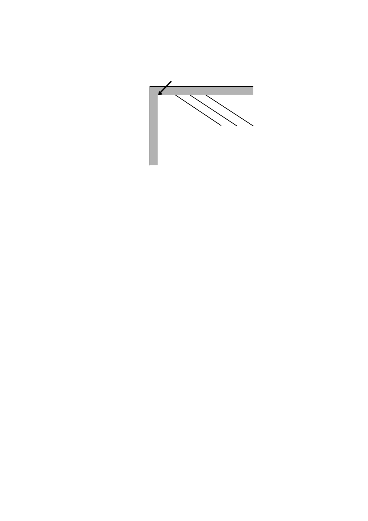
Figure 2. 3. Result of Draw Commands: Relative Lines
Edge limits
In this command sequence, the PRESCRIBE mode begins with the !R!, resets the printing system defaults to permanent settin gs wit h RES;, and es tablis hes a pen width of 0.0 1
inches with the SPD 0.01;.
The MRP (Move to Relative Position) and DRP (Draw to Relative Position) specify
positions in relation to the cursor’s current position.
When the command sequence starts, the cursor is located at the intersection of the left
and top margins. The command MRP 2, 1; on line 3 moves the cursor 2 inches to the
right of its current position, and down 1 inch from its current position. Then the command DRP -1.5, -1; draws a line from that point to a point 1.5 inches to the left of the
cursor position and 1 inch above it. The cursor winds up 0.5 inches to the right of the
point where it started.
Lines 5 to 8 repeat the move-and-draw sequence two more times . Thi s produces three
parallel lines, as shown in the figure on the previous page.
Lines in Terms of Angles
Until now, all of our examples have specified positions in terms of Cartesian (X,Y) coordinates. This example illustrates drawing lines of specified lengths and angles.
!R! RES;
SPD 0.01;
MZP 5, 4;
DRPA 2, 149;
DRPA 2, 221;
DRPA 2, 293;
DRPA 2, 365; CMNT Equivalent to 5 degrees;
DRPA 2, 437; CMNT Equivalent to 77 degrees;
PAGE;
EXIT;
2-5
Page 28

Chapter 2 Graphics Tutorial
Figure 2. 4. Result of Draw Commands: Lines in Angles
The first two lines of this command sequence initiates the PRESCRIBE mode, resets
printing system defaults to permanent settings, and sets the line width to 0.01 inches.
Then the MZP command on line 3 moves the cursor to a point 5 inches to the right of the
left edge limit and 4 inches below the top edge limit.
Next, DRPA 2, 149; on line 4 draws a line two inches long at an angle of 149 degrees.
The angle is measured clockwise from the vertical axis. The subsequent DRPA commands draw additional 2-inch lines at angles that increase in increments of 72 degrees.
As indicated by the CMNT (CoMmeNT) commands, angles that exceed 360 degrees are
equivalent to the remainder of division of the angle by 360.
Drawing Boxes and Circles
PRESCRIBE provides two commands especially for drawing boxes (BOX command)
and circles (CIR command).
Drawing Boxes
The BOX (draw box) command draws a box of a specified width and height. As with the
line drawing commands, the thickness of the line used to draw the box is determined by
the SPD (set pen diameter) command.
The following command sequence draws a box.
!R! RES;
UNIT C;
SPD 0.1;
MZP 3, 3;
BOX 3, 4;
PAGE;
EXIT;
2-6
Page 29

Figure 2. 5. An Example of a Box
Line 1 places the printing system in the PRESCRIBE mode and resets printing system
parameters. The UNIT C; command on the second line sets the unit of measurement to
centimeters, and the SPD (Set Pen Diameter) command on line 3 sets the line width to
0.1 centimeters. (If you omit these two commands, the printing system will print using
the default unit, inches; and the default line width, 3dots.)
Next, the MZP command on line four moves the cursor to the point that is 3 centimeters
to the right of the left edge limit and 3 centimeters below the top edge limit. This is the
starting point from which the box is drawn.
On line 5, BOX 3, 4; draws a box with a width of 3 centimeters and a height of 4 centimeters.
The position of the box with respect to the cursor depends on the positive or negative
value specified for width and height. The box is drawn to the right of the cursor if width
is positive, and to the left of the cursor if width is negative. Similarly, the box is drawn
below the cursor if height is positive, and above the cursor if height is negative. This
relation is illustrated in the figure that follows.
By default, the position of the cursor is not affected by this command. However, you can
also specify an option parameter to make the cursor move to an adjacent or diagonally
opposite corner of the box, down by one text line, or to the left margin on the next text
line. The following figure shows some examples.
2-7
Page 30
Chapter 2 Graphics Tutorial
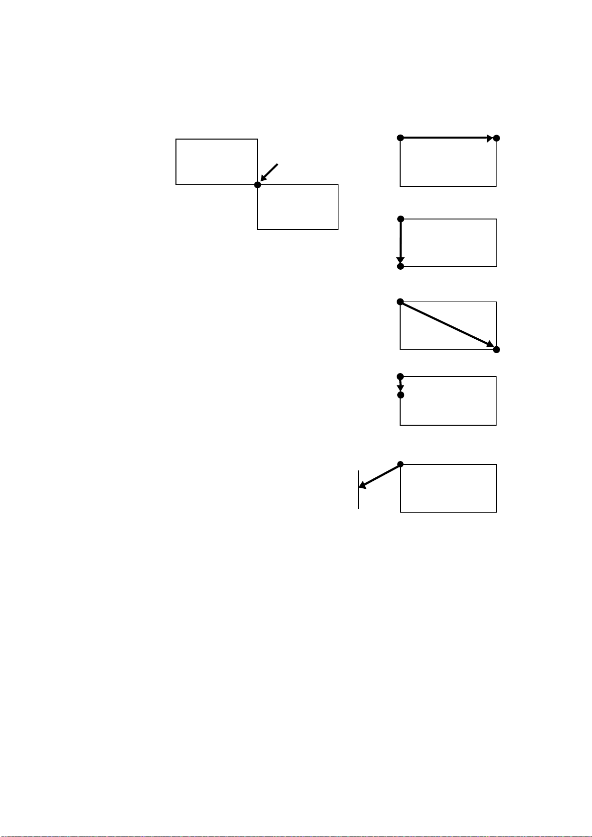
Figure 2. 6. Cursor Positioning Options
BOX 4, 2, H; Moves the cursor to
the horizontally adjacent corner
-Y
-X
Cursor position
X
Y
Left margin
BOX 4, 2, V; Moves the cursor to
the vertically adjacent corner
BOX 4, 2, E; Moves the cursor to
the diagonally opposite corner
BOX 4, 2, L; Moves the cursor
down one line
BOX 4, 2, N; Moves the cursor to
the beginning of the next line (to
the left margin)
2-8
Page 31

Drawing Circles
The CIR (draw circle) command draws a circle of a specified radius using the line thickness set by the SPD (set pen diameter) command. The circle drawn is centered on the
current cursor position; the position of the cursor remains unaffected. See the following
example:
!R! RES;
UNIT C;
SPD 0.1;
MZP 8, 8;
CIR 1;
CIR 2;
CIR 3;
PAGE;
EXIT;
Figure 2. 7. Circles
Lines 1, 2 and 3 start PRESCRIBE mode, reset the printing system to its default parameters, establish the unit of measurement as centimeters, and set the line width to 0.1 centimeters.
Next, the MZP command moves the cursor to the point that is 8 centimeters to the right
of the left edge limit and 8 centimeters below the top edge limit.
Lines 5, 6, and 7 draw three circles with radii of 1, 2, and 3 centimeters.
Drawing Filled Shapes
The standard graphics mode provides two types of filled shapes: arcs and blocks. Such
shapes are filled with one of the printing system’s predefined patterns, or with a user
defined pattern.
Filled areas of other shapes can be printed using path mode graphics. For details, see the
explanation in section Path Mode Graphics on page 16.
2-9
Page 32

Chapter 2 Graphics Tutorial
Drawing Filled Blocks
A filled block consists simply of a rectangle of any desired dimensions. A filled arc is an
area enclosed by an arc segment and the line segments extending from the ends of the arc
to the center of the circle of which the arc is a part.
This section shows how to select a fill pattern and print a filled block or arc.
The following command sequence prints the block shown below.
!R! RES;
UNIT P;
MZP 72, 72;
PAT 6;
BLK 72, -144, H;
PAGE;
EXIT;
Figure 2. 8. A Filled Block
2-10
Lines 1 and 2 put the printing system in the PRESCRIBE mode, reset printing system
parameters and set the unit of measurement to points. (One point is equal to 1/
Next, the MZP command moves the cursor to the position 72 points to the right of the
left edge limit and 72 points below the top edge limit.
The PAT (select fill PATtern) command on line 4 of the program selects the fill pattern.
In this program, pattern number 6 is selected.
You can select from among any of the printing system’s 60 predefined fill patterns or
choose to define a pattern using the XPAT (generate eXpanded PATtern) command. In
either case, the selection is made with the PAT command. For 1200-dpi and 60 0-dpi
models, the user can define the printing resolution (300, 600, 1200 dpi) of the pattern by
giving a second parameter to the PAT command.
You can also select a shade of gray for filling the arc or block by using the GPAT (set
Gray PATtern) command.
It is possible to apply a color to a pattern specified using PAT, FPAT, GPAT or XPAT.
Note, however, that this may not always result in the exact same pattern as printed in
monochrome.
The way a color looks may differ when used for different patterns even though the same
color has been specified.
inches.)
72
Page 33

The BLK (draw filled-in BLocK) command on line 5 actually draws the filled in block.
This command closely resembles the BOX command explained in the preceding section.
However, whereas the BOX command draws a line around a rectangular area, the BLK
command fills a rectangular area with the currently selected pattern.
As with the BOX command, the position of the rectangular area with respect to the cursor depends on the sign of the values specified for width and height. The box is drawn to
the right of the cursor if width is positive, and to the left of the cursor if width is negative; and the box is drawn below the cursor if height is positive, and above the cursor if
height is negative.
As with the BOX command, you can specify an option parameter to make the cursor
move to a specified location after the box is drawn. (The cursor remains unmoved if the
option parameter is omitted.) Values for this option are H, V, E, L, N, and B, the same as
for BOX.
Drawing Filled Arcs
The ARC (draw filled-in ARC) command is similar to the BLK command (described in
the preceding section) in that it fills an area with a pre-defined pattern or a shade of gray .
The arc is drawn centered around the current cursor position. The dimensions of the arc
are determined by user specified inner radius, outer radius, starting angle, and ending
angle.
The following PRESCRIBE demonstrates the ARC command.
!R! CMNT Enter PRESCRIBE mode;
RES; CMNT Reset printing system parameters;
UNIT C; CMNT Set centimeters as unit;
PAT 9; CMNT Select pattern 9;
MZP 8, 8; CMNT Move cursor to point that is 8 cm;
CMNT from left edge limit and;
CMNT 8 cm from top edge limit;
ARC 1, 2, 0, 90;
PAGE;
EXIT;
Figure 2. 9. A Filled Arc
The ARC command on line 8 of the command sequence draws an arc with an inner
radius of 1 centimeter, an outer radius of 2 centimeters, a starting angle of 0 (straight up),
and an ending angle of 90 degrees.
The ARC command does not draw a line around the boundary of the filled-in area.
2-11
Page 34

Chapter 2 Graphics Tutorial
Defining Fill Patterns
With a little work, you can construct your own fill patterns. You can generate 8 × 8 dot
patterns using the FPAT (generate Fill PATtern) command, or 16 × 16 dot patterns using
the XPAT (generate eXpanded fill PATtern) command. This section gives examples of
both.
!R! RES;
MZP 1, 1;
FPAT 16, 40, 68, 130, 65, 34, 20, 8;
BLK 1, 1;
PAGE;
EXIT;
Line 4 of this command sequence prints a filled block using a fill pattern defined by the
FPAT command on line 3.
Each of the eight numbers in the FPAT defines one row of an 8
× 8 dot pattern. The pat-
tern follows:
Figure 2. 10. Dot Pattern and a Filled Block
128
64 32 16 8 4 2 1
16
=
40
=
68
=
130
=
65
=
34
=
20
=
8
=
For this pattern, the numbers across the top indicate the value of each column. The numbers down the right side are the sums of the values of columns that contain black dots in
that row.
2-12
Once this pattern has been defined by the FPAT command, it is used as the fill pattern
until printing system parameters are reset with RES, another pattern is selected with P AT,
a different pattern is defined with FPAT, or a shade of gray is defined and selected by
GPAT.
Now let’s look at an example using the XPAT command.
The XPAT command uses the format
XPAT pattern-number; bit map;
Note that the pattern-number parameter must be a value from 100 to 105 and followed
by a semicolon, not a comma.
The following example demonstrates the XPAT command in a PRESCRIBE command
sequence.
Page 35

!R! RES;
XPAT 100;
@X0@| 0Af0CC0FA8L@<X@6p@3p@3X@6L@<FA8CC0Af0@ | 0@X0;
MZP 1, 1;
PAT 100;
BLK 1, 1;
PAGE;
EXIT;
Lines 2 and 3 define the pattern shown in the figure on the next page, defining it as pattern 100. The PAT command on line 5 selects the pattern for use in fills. Line 6 prints the
filled block.
Figure 2. 11. Dot Pattern and a Filled Block
16 bits
32168421 32168421 8421
6 bits (x) 6 bits (y) 4 bits (z)
+++
64 64 48
The pattern is 16 dots high and 16 dots wide, and is encoded as a series of 16-bit words.
Each 16-bit word is encoded by three characters, representing the most significant six
bits, the next six bits, and the least significant four bits, respectively, as shown on the
next page.
You obtain the characters that define the pattern by dividing each row-work into sections
of six, six, and four bits, calculating the numerical value of each section (referred to as x,
y, and z, respectively), treating it as a binary number in which the white dots are zeroes
and the black dots are ones. Then add 64 (decimal) to the values of the 6-bit sections and
48 to the values of the 4-bit sections. The result is the ASCII code of the character that
represents that section.
2-13
Page 36

Chapter 2 Graphics Tutorial
Column value
32 16 8 4 2 1 32 16 8 4 2 1 8 4 2 1
0+64=64 (@) 24+64=88 (X) 0+48=48 (0)
0+64=64 (@) 60+64=124 (|) 0+48=48 (0)
1+64=65 (A) 38+64=102 (f) 0+48=48 (0)
3+64=67 (C) 3+64=67 (C) 0+48=48 (0)
6+64=70 (F) 1+64=65 (A) 8+48=56 (8)
12+64=76 (L) 0+64=64 (@) 12+48=60 (<)
24+64=88 (X) 0+64=64 (@) 6+48=54 (6)
48+64=112 (p) 0+64=64 (@) 3+48=51 (3)
48+64=112 (p) 0+64=64 (@) 3+48=51 (3)
24+64=88 (X) 0+64=64 (@) 6+48=54 (6)
12+64=76 (L) 0+64=64 (@) 12+48=60 (<)
6+64=70 (F) 1+64=65 (A) 8+48=56 (8)
3+64=67 (C) 3+64=67 (C) 0+48=48 (0)
1+64=65 (A) 38+64=102 (f) 0+48=48 (0)
0+64=64 (@) 60+64=124 (|) 0+48=48 (0)
0+64=64 (@) 24+64=88 (X) 0+48=48 (0)
If the character resulting for section x of any row is @ (indicating that all bits in that section are white), then that character may be omitted. If sections x and y are both @, then
both characters may be omitted. However, if the result for section y is @ and that for section x is a character other than @, then no characters may be omitted. In terms of the program example above, what this means is that the bit map string,
@X0@| 0Af0CC0FA8L@<X@6p@3p@3X@6L@<FA8CC0Af0@ | 0@X0;
may be shortened by four characters to:
X0| 0Af0CC0FA8L@<X@6p@3p@3X@6L@<FA8CC0Af0 | 0X0;
Patterns defined by the XPAT command remain effective until they are redefined by
another XPAT comm and, or until the printing system is turned off.
Drawing Pie Charts
The standard graphics mode provides a convenient function for drawing pie charts. See
the following example:
!R! RES; UNIT C; SPD .05;
MZP 10, 10;
PIE 2, 0, 10, 20, 30, 40;
PAGE;
EXIT;
2-14
Page 37

Figure 2. 12. PIE Example
The PIE command uses the format
PIE radius, starting angle, size of slice, ...;
In the example above, the radius is 2 centimeters (since we set the unit to centimeters
with the UNIT command), and the starting angle is 0 degrees. Four pie slices are specified, with sizes of 10, 20, 30, and 40.
The printing system automatically converts the slice sizes to angles totalling 360
degrees. Then it draws the first slice with a cut at the angle specified by the second
parameter (0 degrees in our example, or straight up). The remaining slices are drawn in
sequence clockwise around the circle. The line thickness used for drawing the circle and
the lines between slices are designated by the SPD (Set Pen Diameter) command.
Any number of pie slice sizes can be specified, provided that the total length of the command does not exceed 255 characters, and that the sum of the pie slices does not exceed
9999. All numbers specified for slice sizes must be non-negative integers.
The PIE command does not fill in the slices with any fill pattern. The PAT command can
be used to create shaded areas. The previous example is expanded to fill in the slices.
!R! RES; UNIT C; SPD .1;
MZP 10, 10;
PAT 19; ARC 0, 2, 0, 36;
PAT 41; ARC 0, 2, 36, 108;
PAT 43; ARC 0, 2, 108, 216;
PAT 48; ARC 0, 2, 216, 360;
PIE 2, 0, 10, 20, 30, 40;
PAGE;
EXIT;
2-15
Page 38

Chapter 2 Graphics Tutorial
Figure 2. 13. Pattern Filled PIE
This program first draws four filled arcs, each using a different fill pattern, then prints
the pie chart over the arcs. Each arc has an inner radius of zero, an outer radius of 2 (the
same as the pie chart), and a starting angle and ending angle that correspond to the relative size of the pie slices. Since the total size of the pie slices in the example is 100
(10+20+30+40), the angular extent of each arc is equal to 360 x size of slice /100. For
example, the angular extent of the first arc is 360 x
angle of each arc equals the starting angle of the pie chart (0 degrees), plus the angular
extent of all the preceding arcs. The ending angle equals the starting angle plus the angular extent of the arc.
10
/
= 36 degrees. The starting
100
Path Mode Graphics
With path mode graphics, images are constructed by defining lines and curves as paths,
then rendering them as images by stroking along the paths or filling the area enclosed by
them. PRESCRIBE provides a variety of path construction operators and painting operators for stroking or filling paths.
Path
In PRESCRIBE, a path is a set of straight or curved line segments, either connected or
disconnected, that describes the shape and position of one or more objects or regions.
Paths can be used to draw lines and curves and to specify boundaries of filled areas.
A path is stroked by drawing a line of arbitrary width along it. The line may be solid
black, all white, or any intermediate shade of gray. It may also be a dashed line of any
pattern of segment lengths.
A path is filled by painting the entire area that it encloses with a gray scale pattern, ranging from black to white, or wi th one of the printing system’ s predefined patterns. In order
to be filled, a path must be closed; that is, it must return to its starting point.
A path is constructed by means of one or more path construction operators. The path
construction operators modify the current path, usually by appending to it. However, a
path in itself does not produce any image on the page. Once a path has been constructed,
it can be used to control the application of one of the painting operators of PRESCRIBE,
defining the boundary of the area in which images can be printed.
2-16
Page 39

Path Mode Graphics
There are no restrictions on the shape of a path. A single path may include multiple
closed subpaths, representing several areas, and a path may intersect itself in an arbitrary
manner.
The order of the segments that define a path is significant. A pair of line segments is said
to connect only if they are defined consecutively , with the second segment starting where
the first one ends. Non-consecutive segments that meet or intersect fortuitously are not
connected.
A subpath is a sequence of connected segments. A path is made up of one or more subpaths. Subpaths may be either open or closed.
Path construction begins with a NEWP (NEW Path) command. Path construction ends
with the CLSP (CLoSe Path) command or with any paint operator that paints the region
enclosed by the path or draws a line along it (such as STRoKe or FILL).
2-17
Page 40

Chapter 2 Graphics Tutorial
Drawing Lines
The following example shows how to draw a line in the path mode.
!R! RES;
NEWP;
PMZP 1, 1;
PDZP 2, 3;
STRK;
PAGE;
EXIT;
Figure 2. 14. Drawing Lines in Path Mode
(1, 1)
(2, 3)
Line 1 of the program switches the printing system to the PRESCRIBE mode and resets
printing system parameters, including the unit (to inches), line width (to 3 dots), and various other aspects of the graphics state.
Path construction begins with the NEWP command on line 2. This command empties the
current path (if any), making it possible to start a new one. In doing so, it makes the position of the cursor undefined.
The PMZP (Path, Move to Zero-relative Position) command on line 3 moves the cursor
to a position one inch from the top and left edge limits of the paper. The coordinates
specified may be positive or negative.
On line 4, the PDZP (Path, Draw to Zero-relative Position) draws a line from the current
cursor position to the position 2 inches from the left edge limit and 3 inches from the top
edge limit. The cursor remains at this position after the line is drawn.
On line 5, the STRK command strokes the path onto the page.
After stroking the current path, the STRK command clears the path in the same manner
as NEWP (start NEW Path).
Finally, PAGE prints out the page, allowing us to look at the result of our work and can-
celling all changes made during the course of the program, then EXIT ends the PRESCRIBE mode.
2-18
Page 41

Two Lines
Path Mode Graphics
The preceding example illustrated construction of a path between points specified in
terms of absolute coordinates. The following program draws two lines, using both absolute coordinate specification and a new method: relative coordinate specification.
!R! RES;
NEWP;
PMZP 1, 1;
PDZP 2, 3;
PMRP .5, -1;
PDRP -1, -1;
SPD 0.04;
STRK;
PAGE;
EXIT;
Figure 2. 15. Drawing Two Lines
(1, 1)
(-1, -1)
(0.5, -1)
(2, 3)
The first four lines of this program are identical to the preceding example. Line 1
switches the printing system to the PRESCRIBE mode and resets printing system parameters, line 2 empties the current path, and lines 3 and 4 draw a line between two points
that are specified in terms of absolute coordinates.
On line 5, the PMRP (Path, Move to Relative Position) command moves the cursor to the
point half an inch to the right and one inch above the current cursor position; that is, the
point at which the first line ends. Then the PDRP (Path, Draw to Relative Position) command on line 6 draws a line to the point 1 inch to the left of the new position and 1 inch
below it.
The line thickness is changed to 0.04 inches by the SPD command on line 7.
Finally, the STRK command on line 8 strokes the path onto the page, PAGE prints out
the page, and EXIT ends the PRESCRIBE mode.
2-19
Page 42

Chapter 2 Graphics Tutorial
Line Ends
The line end type determines how PRESCRIBE renders the ends of lines when they are
stroked onto the page. PRESCRIBE provides three kinds of line ends. These include:
Figure 2. 16. Line Ends
Square caps
Butt caps
Round caps
The default line end type is butt caps. You can switch from the current line end type to
any of the other types with the SCAP command. This command uses the following format:
SCAP line-cap mode;
Values for line-cap mode include:
1 (for square caps)
2 (for butt caps)
3 (for round caps)
Use of this command is illustrated in the following example.
!R! RES;
UNIT C; CMNT Sets unit to cm;
NEWP; CMNT Starts new path;
SPD .5; CMNT Sets line width to .5 cm;
SCAP 1;CMNT Sets square caps;
PMZP 2, 2;
PDZP 4, 4;
SCAP 3; CMNT Sets round caps;
STRK;
PAGE;
EXIT;
Figure 2. 17. Printout of SCAP Example
2-20
Note that the line is rendered with round caps, rather than with square ones. Although
square caps is set before constructing the path, the line type is changed to round prior to
Page 43

Line Joins
Path Mode Graphics
stroking the path. PRESCRIBE refers to the line cap type when the current path is
stroked onto the page, rather than while the path is being constructed. Therefore, the program above renders the line with round caps rather than square ones.
When a path consists of multiple connected line segments, the manner in which they are
stroked onto the page depends on the current line join type.
PRESCRIBE provides four types of line joins. These are called beveled, mitered, round,
and notched. These are illustrated below.
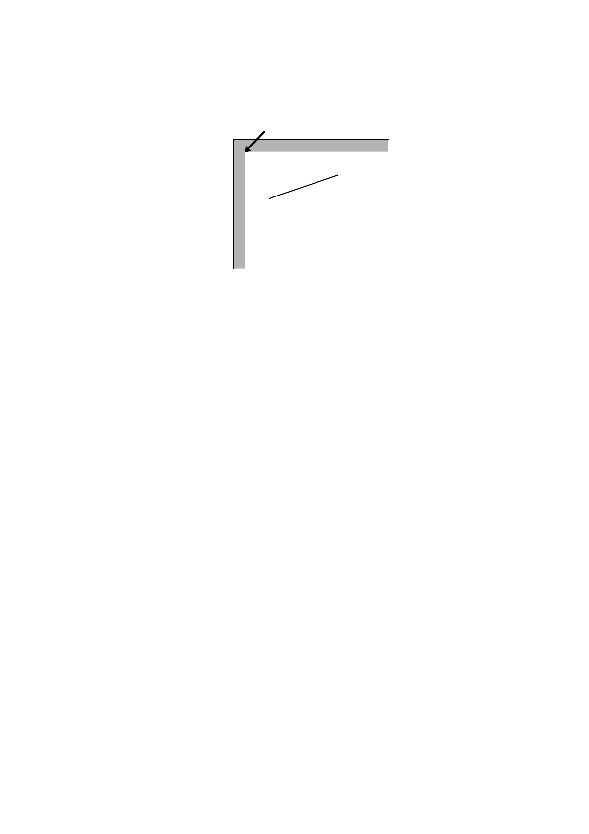
Figure 2. 18. Joins
Beveled join
The default line join type is beveled. With beveled joins, connected line segments end
with butt caps, and the notch at the larger angle between the segments is filled with a triangle.
With mitered joins, the edges of connected line segments are extended until they meet.
This type of join is limited by the miter limit (explained below).
With round joins, connected line segments are joined with circular caps.
Notched joins leave a notch at the larger angle between the connected line segments.
You can switch from the current line join type to any of the other types with the SLJN
(Set Line JoiN) command. This command uses the following format:
SLJN line-join mode;
Mitered join
Round join
Notched join
Values for line-join mode include:
1 (for beveled joins)
2 (for mitered joins)
3 (for round joins)
4 (for notched joins)
Miter Limit
When using mitered line joins, the use of such joins is limited by the miter limit. The
miter limit is the maximum ratio of the distance l between the inner and outer corners of
a mitered join and the width w of the lines joined.
2-21
Page 44

Chapter 2 Graphics Tutorial
Figure 2. 19. Miter Limit
W = line width
W
L = miter length
L
Miter limit = maximum ratio of
/w = 1/
sin
(a/2)
L
If the angle at which lines join is such that this limit is exceeded, the lines are joined with
a beveled join, rather than a mitered one.
The purpose of the miter limit is to prevent objectionably long spikes when lines join at
small angles. The default miter limit is 10, which results in beveled joins at angles of less
than about 11.5 degrees.
You can set any desired miter limit with the SML T (Set Miter LimiT) command. This
command has the following format.
Here are some representative limit-values and the corresponding angles at which the line
join type switches between mitered and beveled.
limit-value appox. angle
260
339
429
523
619
716
814
913
Dash Type
By default, the STRK command strokes paths with solid lines. However, you can also
use a predefined pattern of alternating black and white to stroke paths. This makes it possible to stroke paths as dashed lines. You can also define your own dashed line patterns.
SMLT limit-value;
2-22
The DPAT (select Dash PATtern) command selects one of PRESCRIBE’s ten predefined
dash patterns, or one of 10 dash patterns that you can define yourself. This command
uses the format:
DPAT pattern-number;
Page 45

The following program illustrates use of this command.
!R! RES;
UNIT C; CMNT Sets unit to cm;
NEWP; CMNT Starts new path;
SPD .5; CMNT Sets line width to .5 cm;
PMZP 2, 2;
PDZP 4, 4;
DPAT 5;
STRK;
PAGE;
EXIT;
Figure 2. 20. Printout of the DPAT Example
Path Mode Graphics
In this program, the DPAT command selects the dash pattern with which the line is
stroked.
Predefined dash patterns are selected by specifying values from 1 to 10 for pattern-number. (A value of 1 specifies solid lines.) User-defined patterns can be selected by specifying values from 11 to 20. The next section explains how to use the SDP (Store Dash
Pattern) command to define your own dash patterns. Specifying an undefined user pattern number results in solid black lines.
User Defined Dash Patterns
Using the SDP command, you can define your own dashed patterns for use in stroking
lines, arcs, and curves. See the following example:
!R! RES;
UNIT P;
SDP 11, 2, 2, 5, 2;
UNIT C;CMNT Sets unit to cm;
NEWP; CMNT Starts new path;
SPD .5;CMNT Sets line width to .5 cm;
PMZP 2, 2;
PDZP 4, 4;
DPAT 11;
STRK;
PAGE;
EXIT;
2-23
Page 46

Chapter 2 Graphics Tutorial
Figure 2. 21. Printout of the SDP Example
The SDP command on line 3 defines a dashed pattern consisting of two lengths of black,
two lengths of white, five lengths of black, and two lengths of white. On line 11, the
DPAT command selects this pattern for stroking. The path defined by the PMZP (Path,
Move to Zero-relative Position) and PDZP (Path, Draw to Zero-relative Position) commands is stroked using this pattern, with a result as shown in the figure above.
The SDP command uses the general format:
SDP pattern-number, dash1, space1, dash2, space2, ..., dash10, space10;
The value specified for pattern-number must be in the range from 11 to 20. Dash and
space lengths are specified in pairs. Up to ten dash-space pairs can be specified. The dash
length always comes first in each pair . If a pattern is to begin with a space, then specify 0
for dash1. However, if a pattern ends with a dash, the following space parameter can be
omitted.
Dash patterns defined with this command remain valid until redefined with another SDP
command, or until the printing system is turned off.
Drawing Arcs and Curves
A path can include curves as well as lines. The PARC (Path, draw ARC) and PCRP
(Path, Curve to Relative Position) commands make it possible to draw circular arcs and
arcs of more complex form.
The PARC command uses the format:
PARC x, y, radius, ang1, ang2;
where x and y describe the zero-relative coordinates of the center of the arc, radius
describes the radius of the arc, ang1 describes the arc’s starting angle, and ang2
describes the arc’s ending angle. Coordinates and radius are measured in the unit currently designated by the UNIT command, and the starting and ending angles are measured clockwise from the positive x axis.
The PARC command draws a line between the cursor position and the beginning of the
arc. See the following example:
!R! RES; UNIT C; NEWP; SPD .1;
PMZP 5, 5;
PARC 5, 5, 3, 45, 135;
STRK;
PAGE;
EXIT;
2-24
Page 47

Path Mode Graphics
Figure 2. 22. Printout of the PARC Example
After the arc is drawn, the cursor is located at the end of the arc.
If you wish to eliminate the straight line segment in the above example, leaving only the
arc, the cursor position must be moved in advance to the position at which drawing of the
arc begins. This is shown in the following example, in which the cursor is moved to the
coordinates as specified by the PMRA (Path, Move to Relative position specified by
Angle) command prior to drawing the arc.
!R! RES UNIT C; NEWP; SPD .1;
PMRA 5, 5, 3, 45;
PARC 5, 5, 3, 45, 135;
STRK;
PAGE;
EXIT;
In this current example, the PMRA command moves the cursor from coordinates 5, 5, as
measured from the left and top edge limits of the page, through the distance of 3 centimeters at the angle of 45 degrees from the positive x axis. At this point, the PARC command starts to draw the arc which ends at the angle of 135 degrees.
Figure 2. 23. Printout of the PMRA Example
Circles can be constructed by drawing arcs with angular extents of 360 degrees. To draw
a circle, you will also need a PMRA command to eliminate the line extending from the
center of the circle to the beginning of the circle. See the following example:
!R! RES; UNIT C; NEWP; SPD .1;
PMRA 3, 3, 1.5, 0;
PARC 3, 3, 1.5, 0, 360;
STRK;
PAGE;
EXIT;
2-25
Page 48

Chapter 2 Graphics Tutorial
Drawing Complex Curves
Figure 2. 24. Printout of a Circle Made with PMRA
PRESCRIBE also provides a second curve-drawing operator for constructing complex
curves that are referred to as Bézier curve segments. The PCRP (Path, Curve to Relative
Position) uses the following format.
PCRP x1, y1, x2, y2, x3, y3;
Figure 2. 25. Bézier Curves
x1, y1
Current position
x1, y1
Current position
x2, y2
x2, y2
x2, y2
x3, y3
x3, y3
x1, y1
2-26
Current position
x3, y3
A Bézier curve segment is one that is geometrically defined by a starting point (the cursor’s current position), two control points (x1, y1 and x2, y2), and an ending point (x3,
y3). Coordinates of each of these points are specified as an offset from the cursor’s previous position.
Page 49

Path Mode Graphics
The curve leaves the current position in the direction of x1, y1, and is tangent to the line
between the current position and x1, y1. It bends towards x2, y2, then to x3, y3, and at the
end point, is tangent to the line between x2, y2 and x3, y3. The curve is always entirely
enclosed by the complex quadrilateral defined by the starting point, x1, y1, x2, y2, and
x3, y3.
See the following examples:
!R! RES; UNIT C; NEWP; SPD .1;
PMZP 3, 3;
PCRP 4, 2, 5, 1.5, 6, 1.8;
STRK;
PAGE;
EXIT;
Figure 2. 26. Printout of the PCRP Example
!R! RES; UNIT C; NEWP; SPD .1;
PMZP 3, 3;
PCRP 5.5, 1.5, 1.5, 5.5, 7, 7;
STRK;
PAGE;
EXIT;
Figure 2. 27. Second PCRP Example
2-27
Page 50

Chapter 2 Graphics Tutorial
!R! RES; UNIT C; NEWP; SPD .1;
PMZP 3, 4;
PCRP 4, 2, 5, 4, 6, 2;
STRK;
PAGE;
EXIT;
Figure 2. 28. Third PCRP Example
Setting the Flatness of Curves
When PRESCRIBE renders any curve, it actually converts the curve to a series of connected straight line segments. The length of these line segments is referred to as a curve’s
flatness. Y ou can change the degree of flatness with the FLAT (set FLATness) command.
The default flatness is 1 (dot). Setting smaller values of flatness results in smoother
curves, but more time is required for computing the larger number of line segments
involved. (The difference is not noticeable for a single curve, but can be substantial in
highly complex pages. Also, the difference is more noticeable with lower print resolutions [for example, 300 dpi resolution].)
The following programs illustrate the results of setting the flatness to higher values.
!R! RES; UNIT C; NEWP; SPD .1;
FLAT 30;
PMZP 5, 5;
PCRP 4, 2, 5, 4, 4, 0;
STRK;
PAGE;
EXIT;
Figure 2. 29. Curve with Flatness 30
2-28
Page 51

Path Mode Graphics
!R! RES; UNIT C; NEWP; SPD .1;
FLAT 60;
PMZP 5, 5;
PCRP 4, 2, 5, 4, 4, 0;
STRK;
PAGE;
EXIT;
Figure 2. 30. Curve with Flatness 60
Both of these programs draw an identical curve. The only difference between the two is
in the flatness, which is specified on line 2.
Closed Paths
When the end point of a path connects to its starting point, the path is said to be closed. A
closed path can be stroked, in the same manner as an open path, or it can be filled with
gray-scale shading or a standard mode fill pattern.
Simply ending a path at the path’s starting point does not make it a closed path ; such a
path remains open until it is closed. Closure can be done either explicitly, by means of
the CLSP (CLoSe current Path) command, or implicitly by means of the FILL command.
The following example illustrates construction and closure of a path.
!R! RES; UNIT C; NEWP; SPD .5;
PMZP 4, 2;
PARC 3, 3, 1, 90, 270;
PARC 5, 3, 1, 270, 90;
CLSP;
STRK;
PAGE;
EXIT;
In this example, the PMZP command on line 2 places the current cursor at coordinates 4,
2, where the subsequent P ARC command automati cally starts to draw a line extending to
the beginning of the arc. The PARC command then draws an arc from 90 degrees
(straight up) to 270 degrees (straight down) around the center at coordinates 3, 3. After
the arc is drawn, the cursor is located at the end of the arc. Then the PARC command on
line 4 draws an arc from 270 degrees to 90 degrees around the center at coordinates 5, 3.
Because the cursor position is defined at the end of the first arc when construction of the
second arc starts, the second PARC command draws a line between the end of the first
arc and the beginning of the second one. Finally, the CLSP command on line 5 explicitly
closes the path, thereby constructing a line between the end of the second arc and the
beginning of the first one.
Now the path has been closed. The STRK command goes on to stroke the path, producing the shape shown below.
2-29
Page 52

Chapter 2 Graphics Tutorial
Filled Areas
Figure 2. 31. A Closed Path
!R! RES; UNIT C;
NEWP;
GPAT .5;
PMZP 4, 2;
PARC 3, 3, 1, 90, 270;
PARC 5, 3, 1, 270, 90;
FILL 1;
PAGE;
EXIT;
This program is similar to the previous one. In this case, we choose to fill the path
instead of stroking it. We select a shade of gray for filling the path (.5, a value directly
between black and white) with the GPAT (set Gray PATtern) command on line 3.
First, we construct the path by drawing arcs around the center points. However, we will
not close it explicitly.
Then we execute the FILL command. This implicitly closes the path, drawing a line
between the ending point of the second arc and the starting point of the first one, then
fills the closed path with the selected gray scale pattern.
Note that we could have filled the path with a standard mode fill pattern instead of a
gray-scale pattern. The only change necessary would be to replace the GPAT command
on line 3 with a PAT or FPAT command specifying the pattern to be used.
The format of the FILL command is
FILL rule;
The rule parameter specifies the convention according to which the path is filled.
2-30
Page 53

Path Mode Graphics
With simple convex paths such as that shown below, the entire enclosed area is filled.
Figure 2. 32. Simple Filled Paths
However, when a path consists of multiple closed subpaths or intersects itself as shown
in the next two figures, the rule determines areas that are deemed to be inside the path.
!R! RES; UNIT C;
PMZP 5, 5;
PMRA 5, 5, 2, 0;
PARC 5, 5, 2, 0, 360;
PMRA 5.2, 5.2, 1.5, 0;
PARC 5.2, 5.2, 1.5, 0, 360;
PMRA 5.5, 5.5, 1, 0;
PARC 5.5, 5.5, 1, 0, 360;
FILL 1;
PMZP 10.5, 4.5;
PMRA 10.5, 4.5, 2, 0;
PARC 10.5, 4.5, 2, 0, 360;
PMRA 11, 6, 2, 0;
PARC 11, 6, 2, 0, 360;
PMRA 12, 5, 2, 0;
PARC 12, 5, 2, 0, 360;
FILL 1;
PAGE;
EXIT;
Figure 2. 33. Complex Filled Paths
2-31
Page 54

Chapter 2 Graphics Tutorial
Clipping Rectangle
With 1 specified for the rule parameter of FILL, the method for determining whether a
point is inside the path involves drawing a ray from that point in any direction and counting the number of times the ray crosses segments of the path. The point is said to be
inside the path if the result is an odd number; if the result is an even number, the point is
said to be outside the path.
The non-zero winding rule also draws a ray from a point in any direction to determine
whether or not that point is inside the path and examines the points where a segment of
the path crosses the ray. However, it then starts counting from zero and adds one each
time a segment in the path crosses the ray from left to right; and subtracts one each time
a segment in the path crosses the ray from right to left. If the result of counting all the
crossings is zero, the point is said to be outside; otherwise the point is said to be inside
the path.
After filling the current path, the FILL command clears the path in the same manner as
NEWP.
Up to this point, we have discussed graphics objects to be drawn or stroked or filled as
paths. However, another PRESCRIBE command can be used to define a clipping template for clipping texts, paths, and raster graphics. For this purpose, the CLPR (CLiP
Rectangular region) command is provided to define the rectangular region for clipping
paths.
When the printing system is turned on or reset with PRESCRIBE’s RES command, the
clipping rectangle is identical to the printable limits of the page. Subsequently, executing
the CLPR command reduces the clipping rectangle to the intersection of the objects on
the page and the rectangle defined by CLPR.
The following is an example of CLPR.
!R! RES; UNIT C;
NEWP;
SPD 1;
PMRA 6, 9, 3, 0;
PARC 6, 9, 3, 0, 360;
CLPR 3, 6, 9, 12;
STRK;
EXIT;
In this example, lines 1 through 5 draw a circle with an extra line thickness at the coordinates defined by the PMRA command.
The CLPR command on line 6 constructs a rectangle with its left-upper corner positioned at coordinates 3, 6 and its right-bottom corner positioned at coordinates 9, 12
(both measured from the top and left edge limits of the page).
As with the rectangular area clipping, those parts of the circle that lie outside of the clipping rectangle are erased when the path is stroked, producing the result as shown in the
figure on the next page.
2-32
The rectangle defined by CLPR does not clip the graphics objects which are drawn by
the standard mode graphics commands.
Page 55

Figure 2. 34. Clipping Rectangle Example
Path Mode Graphics
Printing with Character Paths
When a resident scalable (outline) font is selected, you can treat a character as a path and
add it to the current path. The PRESCRIBE command is CPTH (Character PaTH).
Paths created with the CPTH command can be either stroked or filled. See the following
example.
!R! RES;
UNIT P;
NEWP;
PAT 26;
SFNT ’Helvetica-Bd’, 54;
PMZP 72, 144;
CPTH "xyz";
FILL 1;
PAGE;
EXIT;
Figure 2. 35. Character Path
Line 2 of this program sets the unit to printing system’s points (1 point= 1/72 inch), then
the NEWP command on line 3 empties the current path (if any), making ready for construction of a new path. The PAT command on line 4 selects predefined pattern number
26 as the current fill pattern.
2-33
Page 56

Chapter 2 Graphics Tutorial
Next, the SFNT (Select current FoNT by typeface) on line 5 selects Helvetica Bold, a
scalable (outline) font as the current font and scales the font to a height of 54 points. Use
of SFNT and other font selection commands are explained more fully in PRESCRIBE
Commands Command Reference.
The PMZP command on line 6 moves the cursor to the point that is 72 points (1 inch)
from the left edge limit and 2 inches from the top edge limit.
The CPTH command on line 7 constructs a path using the outline of the characters in the
string xyz. The cursor is moved to the end of the string.
Finally, the FILL command fills the path with the selected pattern, and PAGE prints out
the page.
Raster Graphics
While the graphics commands of the standard and path modes draw shapes such as lines,
circles, and boxes, raster graphics commands specify individual dots to draw images.
The dot resolution is selectable from 75 to 300 dots per inch for all models; and 600-dpi
models have two more choices of 200 dpi and 600 dpi. Lower resolutions give a rougher
appearance, but require less raster data for an image of a given size.
Raster graphics are limited in size only by the dimensions of the paper, and in complexity only by the dot resolution.
Raster Data Compression Formats
PRESCRIBE supports raster data in three formats: uncompressed raster data, run-length
encoded raster data, or raster data encoded in tagged image file format (TIFF).
Uncompressed Raster Data
Uncompressed raster data consists of a simple, unencoded bit image consisting of binary
data in which 1 bit represent black dots and 0 bit represent white dots. With this format,
each dot line is divided into 8-dot segments. The settings of dots in each segment are
controlled by the bit values of each byte of raster data. Bit 7 (the highest-order bit in the
first byte of data received) corresponds to the first dot in the dot line, bit 0 corresponds to
the eighth dot, and so forth.
Run-length Encoded Raster Data
With run-length encoding, raster data is encoded in pairs of bytes. The first byte of each
pair indicates a repetition count for the second byte. A value of zero in the first byte indicates that the pattern represented in second byte is not repeated; that is, it occurs only
once. A value of 1 in the first byte indicates that the pattern is repeated once, and so
forth. The first byte can specify any repetition count from 0 to 255.
2-34
Raster Data in Tagged Image File Format
The tagged image file format (TIFF) combines features of the uncompressed format and
run-length encoding. A control byte determines whether the following byte or bytes of
Page 57

raster data represents a repeating pattern or an uncompressed (unencoded) pattern. It also
determines the number of pattern repetitions or bytes of uncompressed data.
The control byte is a two’s complement value that can be either zero, positive, or negative. A negative value (-1 to -127) indicates that the following byte represents a repeating
pattern. The number of repetitions of the pattern is determined by the absolute value of
the control byte.
If the control byte is zero or positive (1 to 127), the following byte(s) of data represent an
uncompressed pattern. In this case, the value of the control byte plus one indicates the
number of bytes making up the pattern.
In TIFF encoding, the two’s complement value -128 indicates a non-operative control
byte. The byte following such a byte is handled as a new control byte.
Commands for Printing Raster Data
PRESCRIBE provides a number of commands for printing raster data, including:
• STR (SeT dot Resolution)
• RVRD (ReceiVe Raster Data)
• ENDR (END Raster data)
• RVCD (ReceiVe Compressed raster Data)
• SRO (Set Raster Options)
Raster Graphics
The principle function of the SRO command is to specify the presentation mode; i.e., the
orientation of the raster image. If the presentation mode is 0 (the default mode), raster
lines print along the width of the physical page, regardless of the current page orientation. If the presentation mode is 1, raster lines print in the orientation of the logical page.
This is illustrated in the figure that follows.
2-35
Page 58

Chapter 2 Graphics Tutorial
Figure 2. 36. Presentation Modes
Presentation mode = 0
X
Current point
Y
Y
Width
Height
Portrait
Presentation mode = 1
X
Current point
Width
Height
Portrait
X
Y
Height
Width
Landscape
Y
Landscape
Current point
X
Current point
Width
Height
A secondary function of the SRO command specifies the width and height of the raster
area. When a width and height are explicitly specified, any part of the raster image that
extends outside of the area is clipped.
The STR command specifies the resolution at which raster data is printed. The default
resolution is 75 dots per inch, or the equivalent of 16 physical dots for each raster-line
dot. The following figure shows how a single raster-line dot correlates to physical dots at
each of the available raster data resolutions.
Figure 2. 37. Dot Resolutions
75 dpi resolution
(Default)
100 dpi resolution
150 dpi resolution
200 dpi resolution
300 dpi resolution
600 dpi resolution
1200 dpi resolution
The RVRD and RVCD commands print raster data in the pr esentati on mode specif ied by
the SRO command and at the resolution specified by the STR command. Either command can be used. The RV RD command can only print uncompressed raster data. The
RVCD command can print uncompressed raster data, run-length encoded raster data, or
2-36
Page 59

tagged image file format raster data. Both commands are used with the ENDR (END
Raster) command.
Printing Raster Data
The normal sequence for printing raster data is to set the presentation mode (and, if
desired, the height and width of the raster image area) with the SRO command, to set the
dot resolution with the STR command, then to print the raster data with the RVRD or
RVCD/ENDR command pair.
Changing the Printing System’s Imaging Model
The printing system’s imaging model governs the way in which images and patterns are
applied to each other. In short, it de termines the transparency or opaqueness of images as
images overlay one another and fill patterns are applied through images.
The image model applies to all PRESCRIBE image modes, and also to operation in the
Hewlett-Packard LaserJet emulation mode.
Raster Graphics
In general, placing any image on a page involves three elements: a pattern, a source
image whose black bits are replaced by the pattern, and a destination image, which is
any earlier image onto which the source image and pattern are placed.
The fill pattern or gray scale pattern is defined by the P AT command, FPAT command, or
GPAT command.
The source image is any raster graphics image, standard mode graphic, lines or shapes
produced by filling or stroking a path, or text printed using any bitmap or scalable font.
The manner in which white bits in the pattern and source image are processed varies
according to the transparency mode. There are two transparency modes: the source
transparency mode and the pattern transparency mode.
When the source transparency mode is 0 (transparent), white bits in the source image
have no effect on the destination image; when the source transparency mode is 1
(opaque), white bits in the source image are applied to the destination image.
Similarly, when the pattern transparency mode is 0 (transparent), white bits in the pattern
do not affect the destination image; but the area of the source image replaced by the pattern dots is applied to the destination image when the pattern transparency mode is 1
(opaque).
The figure on the next page illustrates the results that are obtained by printing images
using image modes; that is, using different combinations of source and pattern transparency modes.
2-37
Page 60

Chapter 2 Graphics Tutorial
Figure 2. 38. Image Models
Source transparency mode = 0 (transparent)
Pattern transparency mode = 0 (transparent)
Source transparency mode = 0 (transparent)
Pattern transparency mode = 1 (opaque)
Source transparency mode = 1 (opaque)
Pattern transparency mode = 0 (transparent)
Source transparency mode = 1 (opaque)
Pattern transparency mode = 1 (opaque)
2-38
PRESCRIBE establishes the printing system’s imaging model with the SIMG (Set
IMaGe model) command. This command uses the following format.
SIMG operation-mode;
operation-mode is a number from 1 to 6 that determines the image model as follows.
Operation mode Source image Pattern
1 Transparent –
2 Opaque –
Page 61

Raster Graphics
3 Transparent Transparent
4 Transparent Opaque
5 Opaque Transparent
6 Opaque Opaque
With operation modes 1 and 2, the SIMG command addresses the transparency of the
source image only. For operation mode 1, the white pixels of the source image do not
overlay on the destination. For example, you cannot pattern a character. With operation
mode 2, the SIMG command applies the white pixels of the source image onto the destination directly.
The following program example illustrates use of the SIMG command. Try changing the
value specified for SIMG on line 3 and see the effect on the result (the figure on the previous page).
!R! RES; UNIT C;
NEWP;
SIMG 3; CMNT Try changing this value;
PMZP 5, 15;
PMRP 2, 2;
PDRP 0, -2, 2, 0, 0, 2, -2, 0;
PDRP -2, 0, 0, 2, 2, 0, 0, -2;
FILL 1;
SFNT ’TimesNewRoman’, 90;
PMRP -1.2, 1;
GPAT .6;
TEXT ’A’;
FILL 1;
PAGE;
EXIT;
Saving and Restoring the Graphics State
The graphics state consists of a variety of items that affect how images are rendered on
the page. The graphics state contains various information related to path mode graphics
and raster mode graphics.
Items included in the graphics state include the following:
• Current path and cursor position (if defined)
• Current pen diameter (line width)
• Current line join type
• Current line cap type
• Current miter limit
• Current dash pattern
• Current flatness
• Current fill pattern (16
• Current clipping rectangle
• Current raster resolution
• Current image model
While working with graphics, there often are occasions when it is useful to save the
graphics state, then later to restore it. One such situation occurs when a path must be
used for both stroking and filling.
× 16 dots)
2-39
Page 62

Chapter 2 Graphics Tutorial
For example, construction of a filled and outlined shape such as that shown below
requires that we draw the path and then fill it. However, filling the path also clears it,
making it unavailable for stroking.
Figure 2. 39. A Path both Stroked and Filled
By saving the graphics state prior to filling the path, it becomes possible to restore the
path after it has been filled, thereby allowing it to be stroked without reconstructing it.
The commands used for saving and restoring the graphics state are the SCG (Save Current Graphics state) command and the RPG (Return to Previous Graphics state) command.
The following program demonstrates the commands for constructing a path that is both
filled and stroked.
!R! RES; UNIT C; NEWP;
PMZP 4, 2;
PARC 3, 3, 1, 90, 270;
PARC 5, 3, 1, 270, 90;
CLSP;
SCG;
STRK;
RPG;
GPAT .5;
FILL 1;
PAGE;
EXIT;
The result appears in the figure above.
2-40
Page 63

Chapter 3
Macros
After you have gone to the trouble of creating (and debugging) a PRESCRIBE command
sequence, it is inefficient to use it only once, but it is a nuisance to type the same
sequence repeatedly. The solution is to make the sequence into a macro. Then you can
execute the entire sequence with a single CALL command. The procedure for defining a
macro command sequence is simple.
Step 1:Assign a name to the sequence. Place the name at the top of the sequence (ending
with a semicolon).
Step 2:Add the PRESCRIBE command MCRO in front of the name.
Step 3:Add the PRESCRIBE command ENDM at the end of the sequence.
Page 64

Chapter 3 Macros
MCRO Command
The MCRO command assigns a name to the sequence of PRESCRIBE commands that
follows, until the ENDM (END Macro) command appears. Thereafter, the entire
sequence of commands can be executed by specifying the assigned name in a single
CALL or AMCR (Automatic MaCRo) command. The MCRO command has the following format.
MCRO name[ dummy sign[, comment];
The name of a macro can be any length but only the first four characters are recognized
by the PRESCRIBE command language. Any distinction between upper and lowercase
letters is also ignored. For example, the following macro names are all the same:
ABCD
abcd
ABCDE
Abcdxyz
The name must start with a letter, but the other characters can include digits and special
symbols such as hyphens. For example, F-1 and GRY2 are valid macro names.
The dummy sign (the default is the percent sign) indicates dummy parameters in the body
of the macro. Dummy parameters enable you to place different variables when the macros are called. By using dummy parameters the same macro will execute differently
according to the values given on the CALL command. Dummy parameters are written by
writing the dummy sign followed by a number: %1 for the first dummy parameter, %2
for the second dummy parameter, and so on up to a maximum of 19 dummy parameters.
The same dummy parameter can be used any number of times. Values are assigned to
dummy parameters when the macro is called by the CALL command.
You do not have to specify the dummy sign in the MCRO command unless you want to
use a dummy sign different from the percent sign or want to specify a comment. The
printing system ignores the comment. A useful comment would be a list of the meanings
of dummy parameters. In particular, a macro can contain the CALL command, permitting one macro to call another. Macro calls can be nested in this way up to a maximum
depth of 20.
If the body of the macro contains TEXT, RTXT, or CTXT commands and these have
dummy parameters, the enclosing quotation marks should be included in the macro call,
not in the macro definition. This enables strings containing commas, semicolons, consecutive spaces, apostrophes, and quotation marks to be printed.
If a macro with the same name has already been defined, the new definition is ignored.
To redefine a macro, you must first delete the old definition with the DELM (DELete
Macro) or DAM (Delete All Macros) command, or by switching the printing system
power off.
3-2
There is no particular limit on the length of a macro. The maximum number of macros
that can be defined is limited only by the amount of the available memory in the printing
system. Each command in a macro is limited to 255 characters in length.
Page 65

Figure 3. 1. PRESCRIBE Macro Limitations
Macro limitations are summarized as follows.
Examples of Macros
Maximum number of macros downloadable
to the printing system
Maximum nesting levels 20
Maximum length of macro name 4 characters
Maximum number of parameters 19
Maximum length of CALL command 255 bytes
PRESCRIBE commands that should not be
contained within a macro definition
Examples of Macros
Example 1
The following macro example draws a circle. It first names the macro that issues the
PRESCRIBE commands for drawing a circle in the middle of a page.
!R! MCRO CIR1;
MZP 4, 5.5; CIR 1;
ENDM;
EXIT;
Depends on the available printing system’ s mem ory
EXIT, LDFC, MCRO, DELM, DAM,
RDMP, ENDD, ICCD, WRED, EPRM
When completed, this macro will draw a circle after it has been sent to the printing system.
!R! CALL CIR1; EXIT;
If you want circles of different sizes, you can make the radius into a so-called dummy
parameter. Dummy parameters in macro definitions are denoted using percent symbols
(%) as below:
!R! MCRO CIRCLE;
MZP 4, 5,5; CIR %1;
ENDM;
EXIT;
After this definition: CALL CIRCLE, 1; draws a one-inch circle, CALL CIRCLE,
2; draws a two-inch circle, and so on. Note the commas are required to separate the
macro name from the radius parameter in these CALL statements.
3-3
Page 66

Chapter 3 Macros
Example 2
!R! RES; UNITC; DAM;
EXIT;
The next file presents a more ambitious project. It makes the graph-drawing commands
in the preceding section into a pair of macros to draw multiple graphs. This file may help
you to better understand the macro creating process. The DAM command in the first line
is a safety precaution that clears any previous macros out of memory.
MCRO LOCATE;
SLM %1;
STM %2;
ENDM;
MCRO GRAPH;
UNIT C;
SPD 0.05; SCS 0.23;
MAP 0, -7.3; TEXT %1;
MAP 0, 0; BOX 6, -7;
MAP -0.1, 0.5;
TEXT ’Sun Mon Tue Wed Thu Fri Sat’;
MAP 0, -%2;
DAP 1, -%3;
DAP 2, -%4;
DAP 3, -%5;
DAP 4, -%6;
DAP 5, -%7;
DAP 6, -%8;
ENDM;
CALL LOCATE, 2, 9;
CALL GRAPH, ’Temperature’, 2.5, 3.5, 1.9, 3.0, 3.8, 2.8, 3.3;
CALL LOCATE, 10, 9;
CALL GRAPH, ’Humidity’, 3.5, 1.0, 1.3, 2.6, 1.8, 6.4, 5.9;
CALL LOCATE, 2, 20;
CALL GRAPH, ’Paid Attendance’, 5.2, 1.1, 0.9, 1.5, 1.3, 3.3, 4.4;
CALL LOCATE, 10, 20;
CALL GRAPH, ’Pages Completed’, 0, 1.2, 4.4, 4.6, 3.2, 6.6, 0;
PAGE;
3-4
Page 67

Figure 3. 2. Macro Example 2
Examples of Macros
3-5
Page 68

This page is left blank intentionally .
3-6
Page 69

Chapter 4
Fonts
This chapter covers font-related topics, including the printing system’s resident and
option fonts, character sets, and usage of font-selection and symbol creation commands.
A font is a set of characters of a particular design. The design is referred to as a typeface.
Several characteristics identify a font. These include the font type (bit map or scalable),
symbol set, spacing, pitch, height, style, stroke weight, and typeface family. In selecting
a font, the printing system searches the available fonts to match these characteristics
based on the highest priority. For details in this regard, see Selecting Fonts Using the
FSET Command on page 4-9 in this chapter.
Page 70

Chapter 4 Fonts
Resident Fonts
The printing system provides one bitmap font and 136 scalable (outline) fonts as the resident fonts. Also, fonts may be downloaded to the printing system’s memory from a
computer or a memory card. These fonts are referred to as downloadable or soft fonts.
The printing system accepts as many downloadable fonts as user memory allows.
When the HP LaserJet is the printing system’s default emulation, the power-up (default)
font is Courier. A different defau lt font can be selected by using the FRPO (Firmware
RePrOgram) command of parameters V3 (or using the printing system’s operator panel
key). For details, refer to FRPO Parameters on page 6-2.
List of Fonts
Resident scalable fonts provide an outline of characters which can be sized according to
sizing information for the font. These fonts can be scaled from 0.25 to 999.75 points in
quarter point increments.
This section shows tables of the printing system’s resident fonts. It is possible to print a
full list of resident fonts by the FLST command (or using the printing system’s operator
panel key). To print a list of fonts, command:
!R! FLST; EXIT;
The following list shows all the resident fonts in the printing system. For example, Univers-Bd means a Universe style scalable font with bold weight.
Font Name
Courier
CGTimes
CGTimes-Bd
CGTimes-It
CGTimes-BdIt
CGOmega
CGOmega-Bd
CGOmega-It
CGOmega-BdIt
Coronet
Clarendon-Cd
Univers-Md
Univers-Bd
Univers-MdIt
Univers-BdIt
Univers-MdCd
Univers-BdCd
Univers-MdCdIt
Univers-BdCdIt
AntiqueOlive
AntiqueOlive-Bd
AntiqueOlive-It
GaramondAntiqua
4-2
Page 71

Font Name
Garamond-Hlb
Garamond-Krsv
Garamond-HlbKrsv
Marigold
Albertus-Md
Albertus-ExBd
Arial
Arial-Bd
Arial-It
Arial-BdIt
TimesNewRoman
TimesNewRoman-Bd
TimesNewRoman-It
TimesNewRoman-BdIt
Helvetica
Helvetica-Bd
Helvetica-Ob
Helvetica-BdOb
Helvetica-Nr
Helvetica-NrBd
Helvetica-NrOb
Helvetica-NrBdOb
Palatino
Palatino-Bd
Palatino-It
Palatino-BdIt
ITCAvantGardeGothic-Bk
ITCAvantGardeGothic-Dm
ITCAvantGardeGothic-
BkOb
ITCAvantGardeGothic-
DmOb
ITCBookman-Lt
ITCBookman-Dm
ITCBookman-LtIt
ITCBookman-DmIt
NewCenturySchoolbook-
Rom
NewCenturySchoolbook-Bd
NewCenturySchoolbook-It
NewCenturySchoolbook-
BdIt
Times-Rom
Times-Bd
Times-It
Times-BdIt
ITCZapfChancery-MdIt
Symbol
4-3
Page 72

Chapter 4 Fonts
Font Name
SymbolPS
Wingdings
ITCZapfDingbats
Courier-Bd
Courier-It
Courier-BdIt
LetterGothic
LetterGothic-Bd
LetterGothic-It
CourierPS
CourierPS-Bd
CourierPS-Ob
CourierPS-BdOb
LinePrinterBM8.5-Roman
(Bitmap)
KPDL Fonts
In KPDL (Kyocera Print-system Description Language) emulation, the printing system
provides PostScript-compatible 47 scalable fonts. These fonts are also accessible by
using the PRESCRIBE command.
Font Name
Albertus-ExtraBold
Albertus-Medium
AntiqueOlive
AntiqueOlive-Bold
AntiqueOlive-Italic
Arial
Arial-Bold
Arial-BoldItalic
Arial-Italic
AvantGarde-Book
AvantGarde-BookOblique
AvantGarde-Demi
AvantGarde-DemiOblique
Bookman-Demi
Bookman-DemiItalic
Bookman-Light
Bookman-LightItalic
CGOmega
CGOmega-Bold
CGOmega-BoldItalic
CGOmega-Italic
CGTimes
CGTimes-Bold
CGTimes-BoldItalic
CGTimes-Italic
4-4
Page 73

Font Name
Clarendon-Condensed-Bold
Coronet
Courier
Courier-Bold
Courier-BoldOblique
Courier-Oblique
CourierPCL
CourierPCL-Bd
CourierPCL-BoldItalic
CourierPCL-Italic
Garamond-Antiqua
Garamond-Halbfett
Garamond-Kursiv
Garamond-KursivHalbfett
Helvetica
Helvetica-Bold
Helvetica-BoldOblique
Helvetica-Narrow
Helvetica-Narrow-Bold
Helvetica-Narrow-BoldOblique
Helvetica-Narrow-Oblique
Helvetica-Oblique
LetterGothic
LetterGothic-Bold
LetterGothic-Italic
Marigold
NewCenturySchlbk-Bold
NewCenturySchlbk-BoldItalic
NewCenturySchlbk-Italic
NewCenturySchlbk-Roman
Palatino-Bold
Palatino-BoldItalic
Palatino-Italic
Palatino-Roman
Symbol
Symbol MT
Times-Bold
Times-BoldItalic
Times-Italic
Times-Roman
TimesNewRoman
TimesNewRoman-Bold
TimesNewRoman-BoldItalic
TimesNewRoman-Italic
Univers-Bold
Univers-BoldItalic
Univers-Condensed-Bold
Univers-Condensed-BoldItalic
4-5
Page 74

Chapter 4 Fonts
Substituting a Bitmap Font
Font Name
Univers-Condensed-Medium
Univers-Condensed-MediumItalic
Univers-Medium
Univers-MediumItalic
Wingdings-Regular
ZapfChancery-MediumItalic
ZapfDingbats
The printing system does not contain any bitmap fonts except LinePrinterBM8.5Roman. If the printing system receives a request for the bitmap fonts that the previous
lineups of the printers supported (tabled on page 4-4), a scalable font is substituted.
For example, if Dutch801BM10-Roman, which means a Dutch 801 style bitmap font of
10-point and Roman-style and was resident to the previous models of Kyocera printers,
the printing system substitutes a Times Roman style scalable font. Other options include
weights for bold and italic.
The following table lists the bitmap fonts and the bitmap font numbers that the previou s
lineups of Kyocera printers support.The Kyocera printing system behaves exactly in the
same manner when it receives these font numbers. It substitutes the scalable fonts for
these fonts when required.
Font Name Font Number Height (Pts.) Pitch (cpi)
Port. Land.
CourierBM12-Roman 1 17 12 10
CourierBM12-Italic 37 18 12 10
CourierBM12-Bold 38 67 12 10
CourierBM12-BoldItalic 39 68 12 10
Dutch801BM10-Roman 2 19 10 Prop.
Dutch801BM10-Italic 3 20 10 Prop.
Dutch801BM10-Bold 4 21 10 Prop.
Dutch801BM10-BoldItalic 40 69 10 Prop.
Dutch801BM8-Roman 5 22 8 Prop.
Dutch801BM8-Italic 41 — 8 Prop.
Dutch801BM8-Bold 42 70 8 Prop.
Dutch801BM8-BoldItalic 43 — 8 Prop.
PrestigeEliteBM10-Roman 6 23 10 12
PrestigeEliteBM10-Italic 44 24 10 12
PrestigeEliteBM10-Bold 45 71 10 12
PrestigeEliteBM10-BoldItalic 46 72 10 12
PrestigeEliteBM7.2-Roman 7 25 7.2 16.67
PrestigeEliteBM7.2-Italic 47 — 7.2 16.67
PrestigeEliteBM7.2-Bold 48 73 7.2 16.67
PrestigeEliteBM7.2-BoldItalic 49 — 7.2 16.67
LetterGothicBM12-Roman 8 26 12 12
4-6
Page 75

Font Name Font Number Height (Pts.) Pitch (cpi)
Port. Land.
LetterGothicBM12-Italic 50 27 12 12
LetterGothicBM12-Bold 9 28 12 12
LetterGothicBM12-BoldItalic 51 79 12 12
LinePrinterBM8.5-Roman 88 — 8.5 16.67
Swiss721BM14.4-Bold 10 29 14.4 Prop.
Swiss721BM14.4-BoldItalic 52 — 14.4 Prop.
Swiss721BM12-Bold 11 30 12 Prop.
Swiss721BM12-BoldItalic 53 — 12 Prop.
Swiss721BM10-Bold 12 31 10 Prop.
Swiss721BM10-BoldItalic 54 — 10 Prop.
Swiss721BM8-Roman 13 32 8 Prop.
Swiss721BM8-Italic 55 — 8 Prop.
Swiss721BM8-Bold 56 74 8 Prop.
Swiss721BM8-BoldItalic 57 — 8 Prop.
Swiss721BM6-Roman 14 33 6 Prop.
Swiss721BM6-Italic 58 — 6 Prop.
Swiss721BM6-Bold 59 75 6 Prop.
Swiss721BM6-BoldItalic 60 — 6 Prop.
LinePrinterBM9-Roman 15 34 9 16.67
LinePrinterBM9-Italic 61 35 9 16.67
LinePrinterBM9-Bold 62 76 9 16.67
LinePrinterBM9-BoldItalic 63 77 9 16.67
LinePrinterBM7-Roman 16 36 7 21.43
LinePrinterBM7-Italic 64 — 7 21.43
LinePrinterBM7-Bold 65 78 7 21.43
LinePrinterBM7-BoldItalic 66 — 7 21.43
Font Selection
Font Selection
There are several ways to select the fonts: one way is to use the appropriate keys on the
printing system’s control panel; a second way is to place a PRESCRIBE command in the
file to be printed, as in the examples in Chapter 1; a third way is to select a printing system driver within a software application. This third way is preferable because the fonts
are integrated directly into the software. In the absence of this support, the user should
read the following information on choosing and placing PRESCRIBE commands.
Font Selection by PRESCRIBE Commands
The PRESCRIBE commands associated with font selection include:
• FSET (change current Font SETting by characteristic)
• SFNT (Select current FoNT by typeface)
• ALTF (select ALTernate Font) and SETF (SET alternate Font)
• SCF (Save Current Font) and RPF (Return to Previous Font)
• SCCS (Save Current Code Set) and RPCS (Return to Previous Code Set)
4-7
Page 76

Chapter 4 Fonts
Selecting Fonts Using the SFNT Command
• CSET (Change current symbol SET)
• FTMD (set bitmap FonT MoDe)
• FONT (select current FONT by number)
• SFA (Set bitmap Font Attributes)
The FTMD and SFA commands are only valid with bitmap fonts (which are simulated
by resident scalable fonts).
The following is a guideline to the use of these commands. Also, these commands are
fully detailed in PRESCRIBE Command Reference.
Use the SFNT command to specify a font by typeface or to assign a font number to a
scalable font, making it possible to select a scalable font with the FONT command (See
Selecting Fonts with the FONT Command on page 4-10.).
For example, to print text using the scalable Times font (TimesNewRoman) at 10 points,
use the following sequence:
!R! SFNT ’TimesNewRoman’, 10; EXIT;
Here, TimesNewRoman represents the typeface name and 10 represents font height in
the unit of points. Note that the SFNT command recognizes all character heights in terms
of points, regardless of the specified unit value.
The SFNT command is particularly useful when you want to assign the font number to a
scalable font and alter its appearance by compressing, expanding, or obliquing it. The
following example selects a scalable Dutch font, sizes it to 10 points, assigns it the font
number 1001 and the Roman-8 symbol set, compresses it to 90 percent of its normal
width, and obliques the font so that it tilts forward at an angle of 13.5 degrees.
!R! SFNT ’TimesNewRoman’, 10, 1001, 277, .9, .3; EXIT;
In this sequence, the assignment of font number 1001 enables it to be selected using the
FONT command. Once this assignment has been made, it remains effective until
changed with another SFNT command or until the power is turned off.
Following the font number assignment, value 277 selects the symbol set Roman-8. A full
list of symbol sets and values appear on the SFNT command page in PRESCRIBE
Commands Command Reference.
The value .9 following the symbol set parameter indicates compression to 90 percent of
normal width. Compression can be specified in a range from 0.3 (30 percent) to 3
(300%).
4-8
Compression = 0.3 Compression = 1 Compression = 3
Finally, the value .3 concluding the font selection sequence specifies a forward tilt of
13.5 degrees. The angle for normal characters is 0. Negative values result in backwardtilting characters. The angle parameter accepts any value from –1 (–45°) to 1 (45°).
Examples appear below.
Angle = –1 Angle = 0 Angle = 1
Page 77

The parameters for symbol set, compression, and obliquing must be either all specified
or all omitted.
Selecting Fonts Using the FSET Command
The FSET command provides a method of selecting fonts based on font characteristics
and font location in the printing system.
Font characteristics upon which selection is based appear in order of priority, from highest to lowest as follows:
Characteristic Priority of selection
Symbol set Highest
Spacing 2 nd
Pitch 3 rd
Point size (height) 4 th
Style 5 th
Stroke weight 6 th
Typeface family 7 th
Location 8 th
Orientation Lowest
Font Selection
In selecting a font, the printing system searches the available fonts to match a characteristic based on the highest priority. If this matching produces only one font, that font is
selected. If many fonts match this highest priority, then matching begins with the next
highest characteristic. The printing system continues going down the list until only one
font is left, then that font is selected.
A font may reside in any of three locations: printing system ROM (for resident fonts, and
option fonts, if installed), memory card (for card option fonts), and printing system RAM
(for downloaded fonts). A font in printing system ROM has lower priority than an identical font on a memory card, and a memory card font has a lower priority than an identical
font in printing system RAM. Also, assuming all other characteristics are the same, a
scalable font has lower priority than a bitmap font (simulated).
The last characteristic checked is the font orientation. If two fonts are found that differ
only in orientation, the one selected is that which matches the page orientation. If only
one font remains and its orientation does not match the orientation of the page, the prin ting system rotates the font to match the page orientation.
The example below shows an FSET command sequence that selects the 12-point,
upright, normal-weight, CGTimes font. (The FSET command sequences for selecting the
resident fonts appear on the font lists.)
FSET 1p12v0s0b4101T;
The FSET command sequence may be followed by a CSET (Change current symbol
SET) command which selects the desired HP symbol set. In the example below , the Windows symbol set is selected.
CSET 9U;
HP symbol set values can be referenced on the CSET command page in PRESCRIBE
Commands Command Reference.
4-9
Page 78

Chapter 4 Fonts
Selecting Fonts with the FONT Command
Bitmap Font Mode
The FONT command uses font numbers to select fonts. A scalable font does not normally have the font number, therefore, you must take one extra step using the SFNT
(Select FoNT by typeface) command. See Selecting Fonts Using the SFNT Command
above. For example, to select the 10-point TimesNewRoman which was assigned with
font number 1001, command:
!R! SFNT ’TimesNewRoman’, 10, 1001;
FONT 1001;
EXIT;
If you use a bitmap font, a change in fonts can also affect the character spacing, line
spacing, and page orientation. This depends on the font mode (FTMD). With bitmap
fonts, setting the font mode to 15 enables the printing system to adjust all these parameters automatically. When you select font 23 (landscape PrestigeEliteBM10-Roman), for
example, the printing system automatically changes the character spacing to 12 characters per inch, the line spacing to about 7.25 lines per inch, and the page orientation to
landscape.
Remember that the font mode is only valid for bitmap fonts. Scalable fonts always adjust
to the current page orientation. Also, with scalable fonts, you must use a line-spacing
adjustment command to set the innate line spacing for the new font.
Each emulation has a default font mode for bitmap fonts which takes effect when the
emulation is enabled. Font mode 15 is the default font mode of the Line Printer emulation. The other emulations have lower default font mode values.
If you use a variety of bitmap fonts, you will probably find font mode 13 most convenient. In font mode 13 character spacing and orientation are always correct, and the line
spacing remains constant when you change fonts. Font mode 13 is the default font mode
of the LaserJet emulation. To select font mode 13 in the other emulations, place the following sequence at the top of your program or file:
!R! RES; FTMD 13; EXIT;
(Place FTMD after RES, because RES resets the font mode.)
One reason for selecting font mode 13 over font mode 15 is that a self adjusting line
spacing feature can create disastrous affects with software applications designed to handle line spacing without the assistance of PRESCRIBE.
For lower font mode, such as the default font modes in emulation modes 1 through 5,
spacing and orientation adjustments may be necessary when you change fonts. Use the
following commands:
SCS (Set Character Spacing) or SCPI (Set Characters Per Inch), to adjust the character
spacing, SLS (Set Line Spacing) or SLPI (Set Lines Per Inch), to adjust the line spacing,
SPO (Set Page Orientation), to adjust the page orientation.
4-10
The following sequences both use the FONT 19; command to select the 10-point Dutch
801 font with landscape orientation and proportional character spacing. Neither sequence
affects the line spacing.
!R! FONT 19; SPO L; SCS 0; EXIT;
or
Page 79

Font Selection
!R! FTMD 13; FONT 19; EXIT;
For making many font changes within a document, use the ALTF (change to ALTernate
Font) and SETF (SET alternate Font) commands instead of FONT. To switch repeatedly
between fonts 6 and 8, for example, place the following sequence at the beginning of
your document:
!R! SETF 1,6; CMNT PrestigeEliteBM10-Roman;
SETF 2, 8; CMNT LetterGothicBM12-Roman;
EXIT;
Then use !R! ALTF1; EXIT ; within the document to select font 6 and !R! ALTF2; EXIT;
to select font 8. The advantages of ALTF and SETF are that:
• The numbers are easy to remember (1 and 2 instead of 6 and 8).
• All the font number assignments are collected in one place, where they can be easily
checked.
• If you change your mind and decide to use LetterGothicBM12-Bold (font 9) instead
of LetterGothicBM12-Roman, all you have to change is one SETF command (from
SETF 2, 8; to SETF 2, 9;).
In emulation modes 1, 2, and 5, the SETF command can team up in a very effective way
with embedded word-processing commands. See Chapter 7 for details.
The SCF (Save Current Font) and RPF (Return to Previous Font) commands enable font
numbers to be managed in stack fashion. These commands are particularly useful at the
beginning and end of macros, and when you are using embedded commands of wordprocessing software. To ensure that the saved font is retrieved with the correct code set,
add the SCCS (Save Current Code Set) and RPCS (Return to Previous Code Set) commands to the SCF and RPF command, respectively.
For instance, to select a font using embedded commands, you can save the current font,
call a new font, enter the text and return to the previous font, as in the following
sequence.
!R! SCF; FONT 7; EXIT; (Text of footnote...)
!R! RPF; EXIT;
This sequence leaves the current font, prints the footnote in font 7 (PrestigeEliteBM7.2Roman), then returns to the previous font.
Placement of Font Commands
It is important to note that most existing word-processing software will not recognize
PRESCRIBE font selection commands. However, this software typically accommodates
embedded print commands whereby the PRESCRIBE command placed in a document is
recognized as a print command and not as document text. The following command
sequence demonstrates the embedded commands which might appear in a document.
Example of an appropriate command placement:
... end of previous paragraph.
!R! ALTF 2; EXIT;
Title or Heading !R! ALTF 1; EXIT;
Start of next paragraph ...
The first ALTF command appears on a blank line. The second ALTF command is placed
at the end of a short title or heading, so that it fits on the same line and does not affect the
line count.
4-11
Page 80

Chapter 4 Fonts
Font Selection by Embedded Commands
Word-processing programs with IBM and Epson printer drivers include support for a set
of specific typefaces. The Kyocera printing system internally assigns these typefaces to
match similar typefaces already in the printing system. Kyocera users may reassign these
fonts to create a custom font list. To make this change, refe r to th e SETF co mman d in
PRESCRIBE Commands Command Reference.
Word-processing programs that support the Diablo 630 printer use embedded ribbon-
color commands. The printing system translates these internally into ALTF commands.
By placing two SETF commands at the top of a file, you can designate any two desired
fonts by ribbon-color commands.
Word-processing programs that support the LaserJet printer have font description commands. Kyocera printing systems understand these commands. You can use them to
select any of the fonts in the printing system.
When you select fonts by selecting your software’s own commands, your software recognizes the command and is not thrown off in its tracking of characters per line or lines
per page. The IBM, Epson, and LaserJet emulations support enough embedded commands to meet nearly all font selection needs. Only in the Line Printer emulation must
you rely wholly on PRESCRIBE commands for font selection.
Details on font selection by embedded command appear in Chapter 7.
Creation of New Symbols and Characters
With a little work, it is possible to design completely new bitmap characters by constructing their dot maps. This technique can be used to obtain special characters and
symbols not provided in any of the symbol sets. The relevant command is the LDFC
(LoaD Font Character) command.
One LDFC command defines one character, specifying its font number, character code,
dimensions, orientation, and bit map. An entire new font can be created by specifying an
LDFC command for each character. The command format appears as follows.
LDFC font, code, height, width, y-offset, x-offset,
cell width, center, rotation, resolution; bit map;
Some of the dimension parameters are specified in dots (1/
are specified in micro dots, a unit of measurement equal to 1/32 of 1 dot. These units are
used regardless of the unit set by the UNIT command. The rotation parameter is a non
executable parameter. It does not change the orientation of the character. Instead, it tells
the printing system what the character’s orientation is, so that the printing system can
adjust the page orientation correctly (when the font mode is 8 or higher), and can select
the font in response to embedded word-processing commands for a particular rotation.
The rotation parameter should be the same for all characters in the font.
300
inch). Other dimensions
4-12
The bit map can be constructed by drawing the character on square-ruled paper (shown
at right) and proceeding as explained below. To demonstrate, we shall encode the bit map
for a small diamond-shaped character (the figure below).
Page 81

Symbol Set
Figure 4. 1. Character dot pattern
The pattern is 13 dots high and 13 dots wide. The pattern is encoded as a series of 16-bit
words. If necessary, blank cells may be added on the right to make the width a multiple
of 16. For this reason, the three extra columns appear on the right (see the figure above).
Each 16-bit word is encoded with three characters, representing the most significant six
bits, the next six bits, and the least significant four bits, respectively, as shown in Defin-
ing Fill Patterns in Chapter 2.
To obtain the character codes, divide the word into sections of six, six, and four bits and
calculate the numerical value of each section (referred to as x, y, and z, respectively),
treating it as a binary number in which the white dots are zeros and the black dots are
ones. Then add an offset of 64 to the values of the six-bit sections and 48 to the values of
the four-bit sections. The result is the ASCII code of the character representing that section (x, y, and z, respectively). Refer to the example of dot map and numerical derivation
in Defining Fill Patterns in Chapter 2. The procedure for the numerical derivation is
identical to creating fill patterns for XPAT.
Six-bit sections consisting of all black dots, as in the middle row of this symbol, are a
special case. They encode by using the ASCII code 127, which is the unprintable delete
code. Character 47 (/) may therefore be used instead.
The resolution may be specified for 300 or 600 (dpi) only in printing system models that
support the 600-dpi resolution printing. LDFC generated 300 dpi characters may print
when the default resolution is 300 or 600 dpi. It is not possible for 600 dpi LDFC generated characters to print at 300 dpi.
The bit map data proceeds from left to right across the character pattern, then from top to
bottom. The data can be formatted by inserting line-feeds, but not spaces. If we assign
this character an x-offset of 0 and a y-offset and cell width of 500 micro dots each, and
make it ASCII code 42 (*) of font 1000, it creates the following LDFC command:
!R! LDFC 1000, 42, 13, 13, 500, 0, 500, 250, 0;
@’0@’0Ap0Ap0Cx00|At0//J80|At0Cx0Ap0Ap0@’0@’0;
UNIT C;
BOX 4.35, 0.75, L;
FONT 1000;
TEXT ’ * * * * * * * * ’;
EXIT;
Symbol Set
The page printing system can produce sets of alphabet, numeric, and symbol characters.
These sets, with each character assigned to a particular code, are known as symbol sets.
4-13
Page 82

Chapter 4 Fonts
The following figure shows all the characters included in the most common symbol set,
HP Roman-8.
Figure 4. 2. Roman-8 Symbol Set
In addition to a large selection of bitmap and scalable fonts, the printing system supports
many symbol sets (also referred to as character sets). The variety of Kyocera supported
symbol sets can be attributed to the numerous printer emulations. Most of those symbol
sets are the same regarding the letters of the alphabet, digits, and basic punctuation
marks, but they differ considerably in their special symbols which lie in the upper half of
the character code table, consisting of character codes 128 through 254 (hex 80 through
FE).
Charts for the available symbol sets in each emulation appear in Chapter 7.
Only the resident fonts can be assigned with a new symbol set. All downloaded fonts
contain specific symbol sets.
International Characters
The INTL (print INTernationaL characters) command provides quick access to printing
characters from a different character set, characters not found in the default symbol set
(US ASCII). By simply using the INTL command with appropriate parameters for language and country code, the Kyocera user can access a wide variety of specific characters.
The following sequence selects the ISO-4 U.K. symbol set for the Swiss721BM8-Roman
font in the HP LaserJet emulation:
!R! UNIT P; CMNT Emulation must be HPLJ;
FONT 13;
INTL 3, 1; CMNT ISO-4 U.K.;
EXIT;
The U.K. symbol set is identical to the US ASCII character set except that it has the
pound currency symbol (\P) in place of the number sign (#).
It should be noted that the symbol set selected by INTL is specific to the currently emulated printer (HP LaserJet in the above example). If the current emulation is changed to
Diablo 630 for the example above (by a SEM command, for example), the INTL command selects the Diablo U.K. symbol set instead of HP ISO-4 U.K. symbol set.
4-14
Selecting HP Symbol Sets
The HP LaserJet emulation has considerably more supported symbol sets than can be
accessed through the INTL command. To establish a symbol set, use one of the following commands.
Page 83

Symbol Set
• CSET (Change symbol SET)
• SFNT (Select current FoNT by typeface)
The CSET command selects a symbol set by specifying its identification code which
closely resembles the command parameters of the HP printer control language. In the
example below, the Windows symbol set is selected.
CSET 9U;
The CSET command may be preceded by an FSET font selection command. Remember
that the symbol set has the highest priority in font selection. The following example still
selects the ISO-4 U.K. symbol set for the Swiss742SWC-Roman font in the HP LaserJet
emulation:
!R! UNIT P;
FSET 1p12v0s0b4148T; CMNT 4148 means Universe;
CSET 1E; CMNT ISO-4 U.K.;
EXIT;
The SFNT command, primarily used to select and size a scalable font as stated previously, also provides the parameter that specifies a symbol set for the font. It has the following format:
SFNT ’typeface’[, height[, font-number[, symbol-set, compression, angle]]];
In the above format, the symbol-set parameter specifies the symbol set for the font desig-
nated by typeface. The symbol-set value must be given together with the compression
and angle parameters. In the example below, the symbol-set value 37 assigns the ISO-4
U.K. symbol set to the Universe medium font.
!R! UNIT P;
SFNT ‘Universe-Md’, 12, 2000, 37, 1, 0;
CMNT 37=ISO-4 U.K.;
EXIT;
The symbol set values are tabled in LaserJet Symbol Sets in Chapter 7.
4-15
Page 84

This page is left blank intentionally .
4-16
Page 85

Chapter 5
Barcodes
This chapter is a tutorial for encoding data into linear barcode and two-dimensional barcodes (PDF barcodes) by using PRESCRIBE commands. The former part of this chapter
deals with how to implement the linear barcodes, the latter part explains the PDF417.
They are step-by-step guide with a direct and practical approach.
Page 86

Chapter 5 Barcodes
Linear Barcodes
The printing system is capable of printing a wide variety of barcodes, with human-readable text if desired. The user need only specify the type of barcode and the data to be
encoded. The printing system performs the rest of the work, including bar and space generation, symbol translation, insertion of start and stop codes, checksum calculation, interleaving, padding, zero suppression, and parity reversal.
The scanability of barcodes is affected by the quality of the paper and the type of scanner
used. Parameters of the BARC command enable the width of the bars and spaces to be
Note
adjusted to compensate for these factors. A certain amount of testing and experimentation
may be needed to find the right parameter values for a particular set of conditions.
PRESCRIBE uses the BARC (draw BARCode) command to execute barcodes. This
printing system feature is described fully in this chapter.
The BARC command uses the following format.
BARC type, flag, ’string’[, short, tall[, bar1, bar2, bar3, bar4, space1, space2, space3,
space4]];
The BARC command prints specified data in barcode form. The cursor is located at the
top left corner of the barcode for types 0 to 38, 40 and 41, and at the bottom left corner of
the barcode for type 39, and does not move.
The type, flag, and string parameters are always required. The other parameters are
optional. The type parameter is a number from 0 to 42 designating one of the barcode
types listed in Numbers outside the range from 0 to 42 are regarded as type 15 (MSI barcode with no check digit).
The flag parameter specifies whether (Y or y) or not (N or n) to print a human-readable
text under the barcode. The text is printed in the printing system’s current font. Any
desired font can be obtained by placing a font selection command before the BARC
command. The flag parameter for barcodes 39 and 40 (USPS) must be N.
The string parameter gives the barcode data enclosed in apostrophes or quotation marks.
The allowable length of the string and the characters that can be included depend on the
barcode type. lists the allowed lengths and character sets.
also lists a default character that is used to fill out strings shorter than the minimum
length and which may be substituted for any illegal characters in the string.
If the string is too long, it is truncated to the maximum allowed length.
Examples:
!R! UNIT I; BARC 11, N, ’123456’; EXIT;
5-2
!R! BARC 0, Y, ’12345678910’; EXIT;
Page 87

The short and tall parameters specify the short and tall bar heights in the unit designated
by the UNIT command (default: inches). The short and tall parameters must be both
specified or both omitted. If they are omitted, the default values as shown in Table 5.3.
must be specified.
Only barcode types 0 to 12, 35 to 38, and 39 have two bar heights. For types 13 to 34, 40,
and 41, the bar height is determined by the short parameter and the tall parameter is
ignored. Even when all bars are the same height, however, the command syntax requires
that when a short parameter is specified, the tall parameter must be specified too.
Examples:
!R! UNIT I; BARC 15, N, ’1234567890’, .2, .2; EXIT;
!R! UNIT I; BARC 8, Y, ’123456’, .6, .7; EXIT;
When two bar heights with human-readable text are used, in some cases the tall bars may
overlap the text.
The bar1 to bar4 and space1 to space4 parameters adjust the width of the bars and
spaces. Fine adjustment of these parameters may be needed to obtain scannable barcodes
for a particular scanner and type of paper. The dots unit (UNIT D;) is convenient.
Barcode 40 (USPS FIM) ignores all these parameters and therefore has a constant height
and space.
Some barcode types have only two classes of widths (bar1, bar2, space1, space2). Others have three or four classes. Regardless of the barcode type, when any width parameter
is specified all eight width parameters must be specified together. In the case of two
classes of widths, dummy values must be specified for bar3, bar4, space3, and space4.
The bar and space width parameters should be specified in ascending order. The maximum specifiable value is 200 dots.
1 ≤ bar1 ≤ bar2 ≤ bar3 ≤ bar4 ≤200 (dots)
1 ≤ space1 ≤ space2 ≤ space3 ≤ space4 ≤ 200 (dots)
5-3
Page 88

Chapter 5 Barcodes
If the bar and space width parameters are omitted, the printing system uses suitable
default values. T able 5.3. indicates the number of width classes and the default values for
each barcode type.
Barcode 19 (Code 39) has two width classes, which are set to 5 and 10 dots respectively
in the example below . Bar1 and space1 are both 5 dots, and bar2 and space2 are 10 dots.
Bar3, space3, bar4, and space4 are all given dummy values of 10.
Examples:
!R! UNIT D;
BARC 19, Y, ’0123ABC’, 60, 60, 5, 10, 10, 10, 5, 10, 10, 10;
EXIT;
The above widths are doubled in the next example.
!R! UNIT D;
BARC 19, Y, ’0123ABC’, 60, 60, 10, 20, 20, 20, 10, 20, 20, 20;
EXIT;
Barcode 36 (EAN 8 with a five-digit supplement) has four width classes, which are set to
10, 20, 30, and 40 dots in the example below. Two bar heights are also used.
!R! UNIT D;
BARC 36, N, ’012345678912’, 180, 220, 10, 20, 30, 40, 10,
20, 30, 40;
EXIT;
5-4
Barcode 39 (USPS POSTNET) prints a POSTNET barcode on a mail piece. The United
States Postal Service (USPS) utilizes POSTNET (POST al Numeric Encoding T echnique)
to process bulk mail and business reply envelopes quickly and efficiently.
Though this barcode accepts any values within the range specified on the previous page,
we recommend that all parameters except type, flag, and string not be specified as the
scanability of the barcode is most effective with the default values. Also the flag parameter for this barcode must be N (do not print human-readable text). See the figure on 8. for
POSTNET barcode location.
Page 89

Barcode 41 (USPS FIM) prints a Facing Identification Mark pattern which may be
printed on the envelope adjacent to the stamp. The combination of a FIM and the POSTNET (barcode 39) barcode enables faster processing by the USPS.
When generating a FIM pattern, all parameters except type, flag, and string are ignored.
The flag parameter must be N. Characters permitted for the string parameter are ‘A’, ‘B’,
‘C’, and ‘D’ only, and each represents one of four different FIM patterns. For example,
Courtesy Replay Mail and stamped reply mail require the FIM-A pattern, while Business
Reply Mail and unstamped (prepaid) return mail require the FIM-C pattern. Also see the
figure on 8 for FIM location.
Barcode 43 (Customer) has four bar heights. Only the shortest and tallest bar heights are
specifiable, the heights for the intermediate two bars being adjusted automatically. Any
values entered for bar and space widths are ignored and defaulted to 1.68 points respectively . The rules for the order of specifiable bar and space widths, bar1≤bar2≤bar3≤bar4
and space1≤space2≤space3≤space4, must be adhered to, however.
Table 5.1. Barcode Types (Sheet 1 of 2)
No. Type
0UPC A
1 UPC A with two-digit supplement
2 UPC A with five-digit supplement
3UPC D-1
4UPC D-2
5UPC D-3
6UPC D-4
7UPC D-5
8UPC E
9 UPC E with two-digit supplement
10 UPC E with five-digit supplement
11 EAN-8
12 EAN-13
13 DUN-14 (Distribution Unit Number, EAN)
14 DUN-16 (Distribution Unit Number, EAN)
15 MSI with no check digit
16 MSI with single mod-10 check digit
17 MSI mod-10 followed by mod-10 check digit
18 MSI mod-11 followed by mod-10 check digit
19 Code 39 with no check digit (USD-3)
20 Code 39 with mod-43 check digit (USD-3)
21 Interleaved two of five (USD-1) with no check digit (See No. 41.)
22 Identicon two of five with no checksum
23 Code 128 (USD-6) manual code change
24 Code 128 (USD-6) automatic code change
25 Code 11 with only ’c’ checksum (USD-8)
26 Code 11 with both ’c’ and ’k’ checksums (USD-8)
27 Code 93 with both ’c’ and ’k’ checksums (USD-7)
28 CODABAR with no check digits (USD-4)
29 Matrix two of five with no checksum
30 Datalogic two of five with no checksum
31 Industrial two of five with no checksum
5-5
Page 90

Chapter 5 Barcodes
Table 5.1. Barcode Types (Sheet 2 of 2)
No. Type
32 Ames with no checksum
33 Delta distance ’a’ (IBM) with no checksum
34 Delta distance ’a’ (IBM) with checksum
35 EAN 8 with two-digit supplement
36 EAN 8 with five-digit supplement
37 EAN 13 with two-digit supplement
38 EAN 13 with five-digit supplement
39 POSTNET (USPS)
40 FIM (USPS)
41 Interleaved two of five (USD-1) with checksum
42 UCC/EAN 128
43 Customer
44 Wide gap CODABAR
Table 5.2. Length, Character Set, and Default (Sheet 1 of 2)
Type Length Character set Default
11
0
13
1
16
2
13
3
18
4
22
5
25
6
29
7
6
8
8
9
11
10
7
11
12
12
13
13
15
14
1-14
15
1-14
16
1-14
17
1-14
18
19201–40
0123456789 0
$%+-./0123456789ABCDEFGHIJK LMNOPQRSTUVWXYZ
Space
and space
1–40
21222–26
0123456789 0
1–25
23241–40
All printable characters (ASCII codes 32 to 126) Space
2–40
25261–45
-0123456789 Space
1–45
27 1–50 All printable characters (ASCII codes 32 to 126) Space
28 3–32 $+-./0123456789:abcdetn* –
5-6
Page 91

Table 5.2. Length, Character Set, and Default (Sheet 2 of 2)
Type Length Character set Default
29
30
31
1–25
1–25
1–25
0123456789 0
32 1–25 -0123456789 0
33341–25
0123456789KLMO 0
1–25
35
36
37
38
9
12
14
17
0123456789 0
39 139 0123456789 –
40 1 One of the following FIM pattern types:
0
A – Country Reply Mail with POSTNET.
B – Business Reply, Penalty and Franked Mail without POSTNET.
C – Business Reply, Penalty and Franked Mail with POSTNET.
D – OCR Readable Mail without POSTNET.
41 125 0123456789 0
42 80 All printable characters (ASCII codes 32 to 126)
43 1-20 0123456789ABCDEFGHIJKLMNOPQRSTUVWXYZ –
44 3-32 $+-./0123456789:abcdetn* and space –
5-7
Page 92

Chapter 5 Barcodes
Table 5.3. Location of POSTNET and FIM
3”
2”±
1
/8”
POSTNET
(BARC 39)
Clear Zone
5
(
/8” × 4-1/2”)
Not drawn to scale
Table 5.4. Bar Height and Width Classes
Preferred location
for left-most bar
1
/8”
5
/8”
1
/4”
4-
Barcode read area
1
1
1”-
/4”
FIM (BARC 40)
Clear Zone
Preferred base height
4” max.
/2”
3-
1”-
Stamp
1
/4” min.
3
/4”
7
/16”
3
/16”
5
/8”min.
Type Tall bars Width classes Default (dots)
12341234
0 Yes Yes Yes Yes Yes 6 12 18 24
1 Yes Yes Yes Yes Yes 6 12 18 24
2 Yes Yes Yes Yes Yes 6 12 18 24
3 Yes Yes Yes Yes Yes 6 12 18 24
4 Yes Yes Yes Yes Yes 6 12 18 24
5 Yes Yes Yes Yes Yes 6 12 18 24
6 Yes Yes Yes Yes Yes 6 12 18 24
7 Yes Yes Yes Yes Yes 6 12 18 24
8 Yes Yes Yes Yes Yes 6 12 18 24
9 Yes Yes Yes Yes Yes 6 12 18 24
10 Yes Yes Yes Yes Yes 6 12 18 24
11 Yes Yes Yes Yes Yes 6 12 18 24
12 Yes Yes Yes Yes Yes 6 12 18 24
13 — Yes Yes — — 6 12 (18) (24)
14 — Yes Yes — — 6 12 (18) (24)
15 — Yes Yes — — 6 12 (18) (24)
16 — Yes Yes — — 6 12 (18) (24)
17 — Yes Yes — — 6 12 (18) (24)
18 — Yes Yes — — 6 12 (18) (24)
19 — Yes Yes — — 6 12 (18) (24)
20 — Yes Yes — — 6 12 (18) (24)
21 — Yes Yes — — 6 12 (18) (24)
5-8
Page 93

Table 5.4. Bar Height and Width Classes
Type Tall bars Width classes Default (dots)
12341234
22 — Yes Yes — — 6 12 (18) (24)
23 — Yes Yes Yes Yes 6 12 18 24
24 — Yes Yes Yes Yes 6 12 18 24
25 — Yes Yes Yes — 6 14 21 (21)
26 — Yes Yes Yes — 6 14 21 (21)
27 — Yes Yes Yes Yes 6 12 18 24
28 — Yes Yes — — 6 18 (18) (18)
29 — Yes Yes — — 6 12 (18) (24)
30 — Yes Yes — — 6 12 (18) (24)
31 — Yes Yes — — 6 12 (18) (24)
32 — Yes Yes — — 6 12 (18) (24)
33 — Yes Yes Yes — 6 12 18 (24)
34 — Yes Yes Yes — 6 12 18 (24)
35 Yes Yes Yes Yes Yes 6 12 18 24
36 Yes Yes Yes Yes Yes 6 12 18 24
37 Yes Yes Yes Yes Yes 6 12 18 24
38 Yes Yes Yes Yes Yes 6 12 18 24
41 — Yes Yes — — 6 12 (18) (24)
42 — Yes Yes Yes Yes 6 12 18 24
44 — Yes Yes — — 6 18 (18) (18)
Table 5.5. Bar Height, Width, Pitch, and Spacing for types 39, 40, and 43
Type Height Width Pitch Spacing
39 Tall: 0.125" Short: 0.05" 0.02" 21 bars/inch 0.0475"
40 5/8" 0.031" 1/16" (Tilt: ±5°)
43 Tall: 10.2pt. Short: 3.4 pt. 1.68pt. – 1.68 pt.
5-9
Page 94

Chapter 5 Barcodes
Two-dimensional Barcodes
PDF 417 is a two-dimensional stacked barcode symbology capable of encoding over a
kilobyte of data per label. This is important for applications where a barcode must be
more than merely an identifier, an index to reference a database.
The portable data file approach is well suited to applications where it is impractical to
store item information in a database or where the database is not accessible when and
where the item's barcode is read. Because a PDF417 symbol can store so much data, item
data such as the content of a shipping manifest or equipment maintenance history can be
carried on the item, without requiring access to a remote database.
Encoding data into a PDF417 barcode is a two-step process. First, data is converted into
codeword values of 0-928, which represent the data. This is high-level encoding. Then
the values are physically represented by particular bar/space patterns, which is low-level
encoding. Decoding is the reverse process.
In addition, PDF417 is an error-correcting symbology designed for real-world applications where portions of labels can get destroyed in handling. It performs error correction
by making calculations, if necessary, to reconstruct undecoded or corrupted portions of
the symbol.
PDF417 Symbol Description
At first glance, a PDF417 symbol looks like a set of stacked barcodes. When we look
closer to analyze how the symbol is put together, there are several key elements. These
are rows, start patterns, stop patterns, codewords, and modules, whose definitions are
explained below.
module
The narrowest width of a bar or space in the barcode. All bars or spaces are multiples (up
to six times) of this width. The nominal unit of measure.
codeword
A single group of bars and spaces (or elements) representing one or more numbers, letters, or other symbols (i.e., codeword values for the data to be encoded). Each PDF417
codeword contains four bars and four spaces, for a total of 17 module widths. Each
codeword starts with a bar and ends with a space. See figure below.
1-module width
5-10
3-module wide bar
0 0 0 1 0 1 0 1 0 0 0 1 1 1 1 1 1
Page 95

start pattern
A unique pattern of light and dark elements which indicates the leftmost part of a barcode label.
stop pattern
A unique pattern of light and dark elements which indicates the rightmost part of a barcode label.
row
A lateral set of elements made up of a start pattern, codewords, and a stop pattern. Each
PDF417 symbol must have at least 3 rows. See figure below.
Start pattern
Quiet zone
In each row, between left and right row indicators, there may be from 1 to 30 data
codewords. Collectively, among all rows, these codewords form data columns.
Overall Symbol Structure
Any PDF417 symbol is made up of at least 3 rows, and at most 90 rows. The minimum
number of codewords in a row is 3; this includes the left row indicator codeword, 1 data
codeword, and the right row indicator.
Every symbol contains 1 codeword (the first data codeword in row 0) indicating the total
number of data codewords within the symbol, and at least 2 error-detection codewords.
General PDF417 symbol structure is indicated in the following diagram:
Left row indicator
codeword
Data codeword
Right row indicator
codeword
Stop pattern
Quiet zone
Row 1
Row 2
Row 3
Quiet zone
Row 4
Quiet zone
5-11
Page 96

Chapter 5 Barcodes
Left row indicators Right row indicatorsData codeword area
L0
L1
Start
Lm-2
Lm-1
dn-2
dn-1
Error correction area
d0
Ck-1 Ck-2
C0
C1
R0
R1
Rm-2
Rm-1
Printing a Two-dimensional Barcode
XBAR, XBCP , XBUF, and ENDB commands support two-dimensional barcode printing.
Each command does the following to put data together for printing a barcode.
XBAR Prints a two-dimensional barcode from the given data string. Must
be followed by an ENDB command.
XBCP Specifies various options for the barcode to be printed using XBAR
depending on the mode following the command (0 through 19). See
Macro PDF417 on page 14.
XBUF Defines a buffer name for a data input for XBAR command.
ENDB Terminates a XBAR command sequence.
Stop
Functions of XBCP
The mode parameter in XBCP command format identifies th e vari ous fun ctio ns as li sted
below. These commands are detailed in the PRESCRIBE Commands Command
Reference.
XBCP mode Meaning
XBCP 0 Reset
XBCP 1 Narrowest element width
XBCP 2 Error correction (by percentage)
XBCP 3 Error correction (by predetermined level)
XBCP 4 Number of rows
XBCP 5 Number of columns
XBCP 6 Aspect ratio of height and width
XBCP 7 Bar height by a ratio of element width
XBCP 8 Number of rows and columns (XBCP 4 and 5)
XBCP 9 Truncation
XBCP 10 through 19 These modes give additional control options used to support Macro
PDF417 barcodes. See more details in section Macro PDF417.
5-12
Page 97

Positioning the Barcodes
The following commands are positioning commands the PRESCRIBE language provides. These commands are useful and sometimes essential for proper positioning of the
barcodes onto a medium such as label. More detailed discussion on these (and some
other) positioning commands can be found in the PRESCRIBE Commands Command
Reference.
By default the cursor is located at the top left corner of the barcode and stays there after
printing is done.
MAP Moves the cursor to a position relative to the top and left margins.
MRP Moves the cursor from the current to a specified relative position.
MZP Moves the cursor to a position relative to the top and left edge limits
of the page.
UNIT Sets the unit of measurement used in the PRESCRIBE commands
including the above. The initial unit is inches. The other units are
related to inches as: 1 inch=2.54 centimeters=72 points=300 or 600
dots (depending on the printing system model).
Limitations of Two-dimensional Barcode
Item Description
Encodable character set 256 international characters and binary data
Code type Continuous
Character self checking Yes
Bi-directional decoding Yes
Number of row indicator
codewords required per row
Number of symbol checksum
codewords required
Minimum number of rows per
symbol
Maximum number of rows per
symbol
Minimum number of data columns 1
Maximum number of data col-
umns
Number of symbol length descrip-
tors required
Smallest nominal element width 0.0075 inch or 0.191 mm
Smallest nominal element height 0.01 inch or 0.254 mm
Maximum data characters per
symbol
2
2
3
90
30
1
Assuming 928 codewords – 1 symbol length descriptor – 2 symbol checksum codewords = 925 data
codewords. Binary/ASCII plus mode: 1108 bytes.
Extended alphanumeric compaction mode (EXC):
1850 ASCII characters. Numeric compaction mode:
2725 digits.
For Macro PDF417, which transparently distributes information among a number of
PDF417 symbols, the above storage limits are increased to more than one million bytes
in Binary/ASCII Plus mode and morethan 2.5 million bytes in EXC mode.
5-13
Page 98

Chapter 5 Barcodes
Macro PDF417
Note
Macro PDF417 provides a powerful mechanism for creating a distributed representation
of files too large to be presented by a single PDF417 barcode. Macro PDF417 barcodes
differ from ordinary PDF417 barcodes in that they contain additional control options
which are added by modes 10 through 19 of the XBCP command. This allows a reader to
make use of this information to correctly reconstruct and verify the file, independent of
the barcode scanning order.
The terminology PRESCRIBE macro and macro PDF are not the same. Refer to the
PRESCRIBE Commands Command Reference for the PRESCRIBE macro commands
(MCRO, ENDM, etc.).
The following modes of XBCP are used for Macro PDF417 to represent additional control options for XBAR. Note that implementation of these parameters are optional except
XBCP 17 and XBCP 18.
XBCP 10 File name
XBCP 11 Block count
XBCP 12 Ti me stamp
XBCP 13 Sender ID
XBCP 14 Addressee ID
XBCP 15 File size
XBCP 16 Check sum
XBCP 17 File ID
XBCP 18 Macro PDF417 execution
XBCP 19 Distributed barcodes positioning
Creating a Macro PDF 417 Representation
A Macro PDF417 creation begins with giving fileid using XBCP 17 for the ensuing
Macro PDF417 sequences. Each one XBAR command sequence is needed for each
divided barcode which is succeeded by a XBCP 18 statement that defines a separate
block index for each barcode. The block index is needed to ensure that the divided barcodes are reconstructed in the correct order as the whole file when the barcodes are read.
The basic command sequence for Macro PDF417 is as follows.
...
XBCP 17, ’fileid’; Gives the same file ID to all distributed barcodes.
MZP x1, y1; Position the first barcode at (x1, y1).
XBCP 18, 0; Block index for the first barcode.
XBAR; data_string;ENDB; Encode and print the first divided barcode.
MZP x2, y2; Position the second barcode at (x2, y2).
XBCP 18, 1; Assign block index 1 to the second barcode.
XBAR; data_string;ENDB; Encode and print the second divided barcode.
MZP x3, y3; Position the second barcode at (x3, y3).
XBCP 18, 2; Assign block index 2 to the second barcode.
...
The largest allowed block index is 99,998. Thus, up to 99,999 Macro PDF417 barcodes
may comprise the distributed representation of a data file.
5-14
Page 99

Some samples for Macro PDF417 are provided in PRESCRIBE Commands Command
Reference on th e XBCP pag e.
5-15
Page 100

Chapter 5 Barcodes
5-16
 Loading...