

Kyocera PF-75 Service Manual

PF-75

CONTENTS
1-1 Specifications
1-1-1 Specifications ....................................................................................................................................... 1-1-1
1-1-2 Parts names ......................................................................................................................................... 1-1-2
1-1-3 Machine cross section.......................................................................................................................... 1-1-3
1-1-4 Drive system ........................................................................................................................................ 1-1-4
1-2 Installation
1-2-1 Unpacking ............................................................................................................................................ 1-2-1
1-2-2 Installing the dehumidifier heaters (service part) ................................................................................. 1-2-2
1-3 Troubleshooting
1-3-1 Paper misfeed detection ...................................................................................................................... 1-3-1
(1) Paper misfeed indication ................................................................................................................ 1-3-1
(2) Paper misfeed detection conditions................................................................................................ 1-3-1
(3) Paper misfeeds............................................................................................................................... 1-3-3
1-3-2 Self-diagnosis....................................................................................................................................... 1-3-5
(1) Self-diagnostic function .................................................................................................................. 1-3-5
(2) Self-diagnostic codes ..................................................................................................................... 1-3-6
1-3-3 Electrical problems ............................................................................................................................... 1-3-8
(1) The large paper deck does not operate when the copier main switch is turned on........................ 1-3-8
(2) The deck paper conveying motor does not operate. ...................................................................... 1-3-8
(3) Paper deck motor 1 does not operate. ........................................................................................... 1-3-8
(4) Paper deck motor 2 does not operate. ........................................................................................... 1-3-8
(5) Paper feed clutch 1 does not operate............................................................................................. 1-3-8
(6) Paper feed clutch 2 does not operate............................................................................................. 1-3-9
(7) The paper conveying clutch does not operate................................................................................ 1-3-9
1-3-4 Mechanical problems ......................................................................................................................... 1-3-10
(1) No primary paper feed. ................................................................................................................. 1-3-10
(2) Paper is fed askew. ...................................................................................................................... 1-3-10
(3) Multiple sheets of paper are fed at one time. ............................................................................... 1-3-10
(4) Paper jams. .................................................................................................................................. 1-3-10
(5) Abnormal noise is heard. .............................................................................................................. 1-3-10
5FF
1-4 Assembly and Disassembly
1-4-1 Precautions for assembly and disassembly ......................................................................................... 1-4-1
(1) Precautions..................................................................................................................................... 1-4-1
1-4-2 Paper feed section ............................................................................................................................... 1-4-2
(1) Detaching and refitting the upper and lower deck separation rollers.............................................. 1-4-2
(2) Detaching and refitting the deck paper conveying unit assembly................................................... 1-4-3
(3) Detaching and refitting deck paper feed rollers 1 and 2 ................................................................. 1-4-3
(4) Adjusting the position of the center adjuster (center line alignment) .............................................. 1-4-4
(5) Adjusting the amount of slack......................................................................................................... 1-4-5
2-1 Mechanical construction
2-1-1 Mechanical construction....................................................................................................................... 2-1-1
2-2 Electrical Parts Layout
2-2-1 Electrical parts layout ........................................................................................................................... 2-2-1
1-1-1
2-3 Operation of the PCBs
2-3-1 Deck main PCB .................................................................................................................................... 2-3-1
(1) Paper deck motor drive circuits ...................................................................................................... 1-4-2
(2) Operating principle of reflective photosensors
PPSENS1, PPSENS2, PPSENS3 and PESENS ........................................................................... 1-4-3

5FF
2-4 Appendixes
Timing chart No. 1 .......................................................................................................................................... 2-4-1
Timing chart No. 2 .......................................................................................................................................... 2-4-2
Wiring diagram ............................................................................................................................................... 2-4-3
1-1-2

1-1-1 Specifications
5FF
Paper..............................................Plain paper (75 – 80 g/m2)
Paper size ......................................A4, B5, 11" × 8
1
/2"
Capacity .........................................3000 sheets (1500 sheets × 2)
Power source .................................Electrically connected to the copier
Dimensions .................................... 585 (W) × 590 (D) × 315 (H) mm
1
/16" (W) × 231/4" (D) × 123/8" (H)
23
Weight ............................................ 35 kg/77.2 lbs
1-1-1
5FF
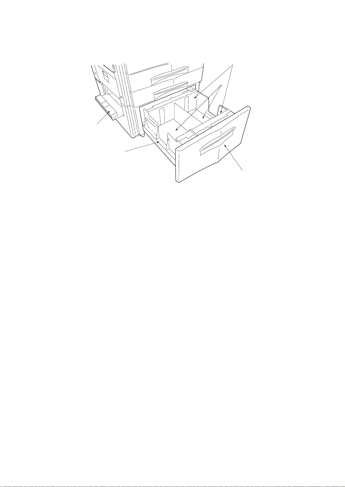
1-1-2 Parts names
5
1
2
3
4
Figure 1-1-2 Parts names
1 Lifts
2 Deck side cover
3 Drawer
4 Deck front cover
5 Paper side guides
1-1-2
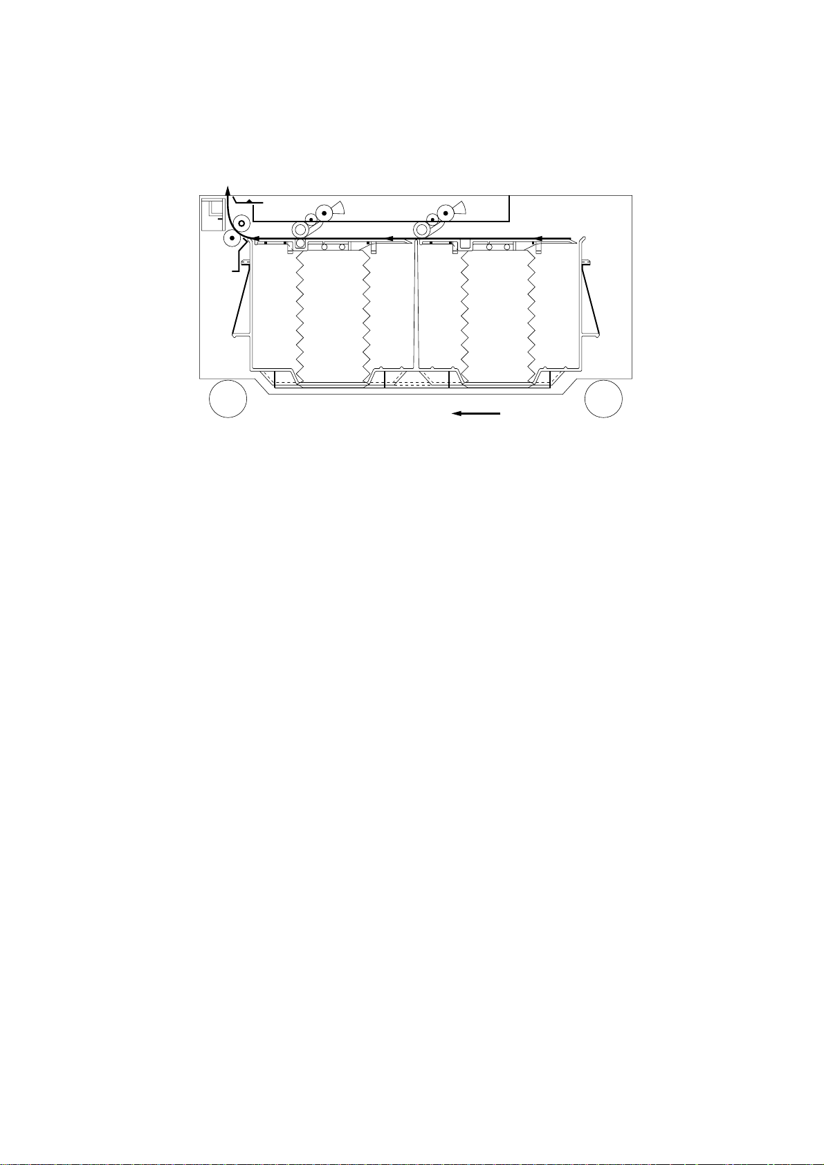
1-1-3 Machine cross section
5FF
Paper path
Figure 1-1-3 Machine cross section
1-1-3
5FF
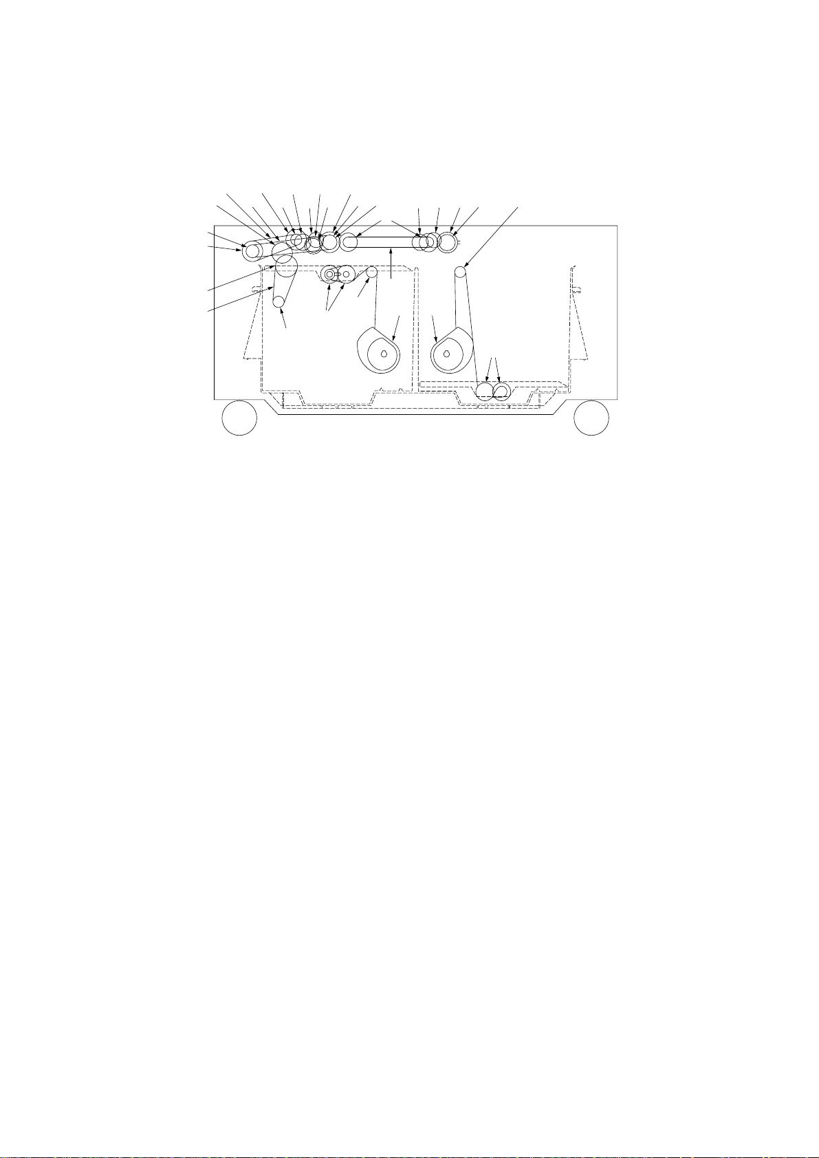
1-1-4 Drive system
3(6805@!7845 ^
4)794
2
1
%
⁄
#
^
(
&*
$
#
As viewed from machine front
Figure 1-1-4
1 Pulley 2M-40
2 Pulley S3M-16
3 Gear 0.8-35/1-20
4 Gear 2.6
5 Gear 0.8-23
6 Pulley 2M-18
7 Pickup roller gear 0.8-23
8 Gear 0.9-26
9 Gear 30
0 Gear 0.8-24
! Pulley 3M-18
@ Pulley 14, gear 0.8-32
# Gear 1.0-24
$ Pulley S2M-18
% Pulley 43, gear 20
^ Lift pulley
& Left lift belt assembly
* Right lift belt assembly
( Belt S3M276
) Belt 2M0950
⁄ Belt 2M0840
1-1-4
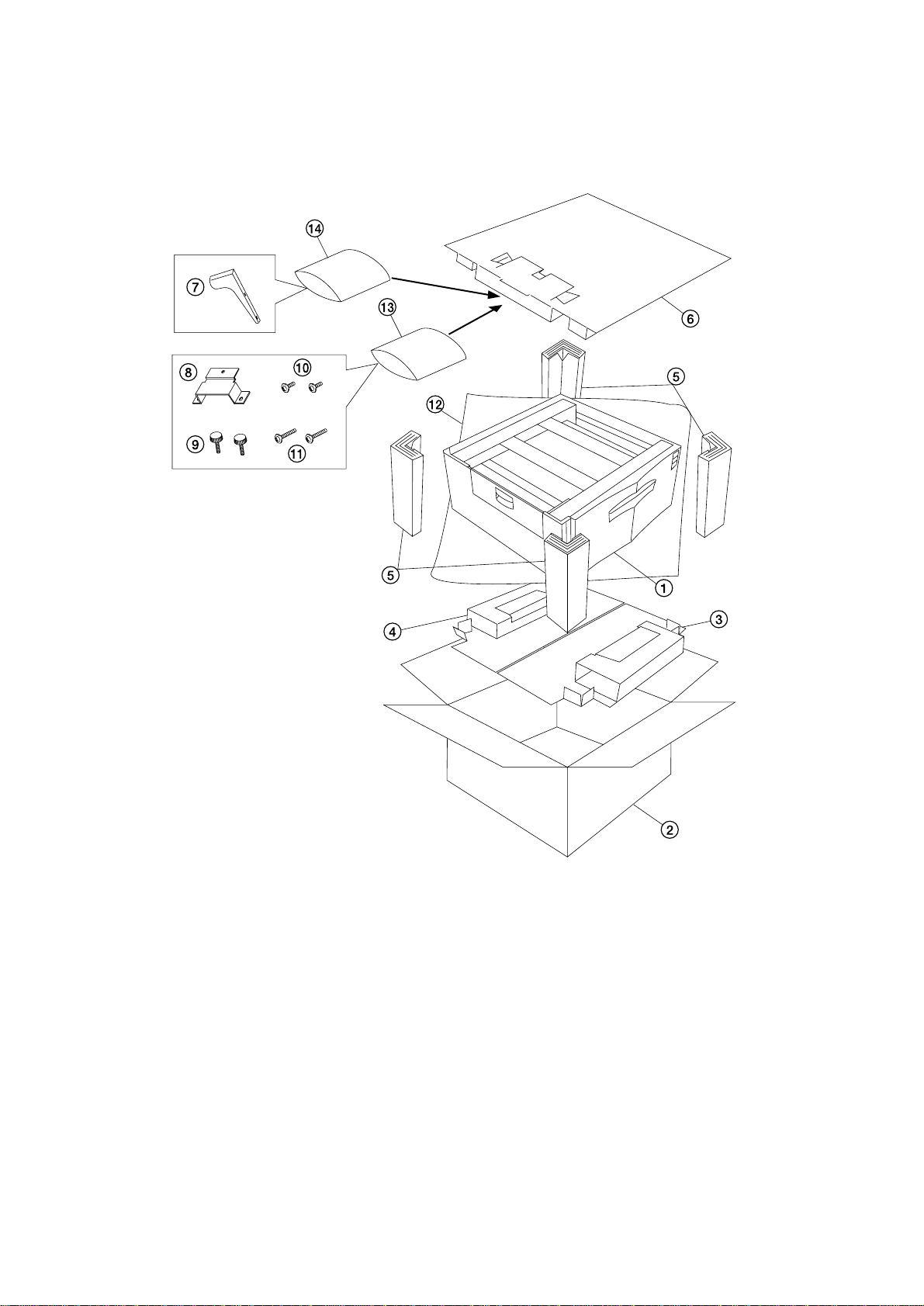
1-2-1 Unpacking
5FF
1 Large paper deck
2 Outer case
3 Lower front pad
4 Lower rear pad
5 Support
6 Upper pad
7 Stay
Figure 1-2-1
8 Retainer
9 Pins
0 Cross-head chromate binding screws,
CVM4 × 06
! Chrome TP screws, M4 × 16
@ Machine cover
# Plastic bag
$ Plastic bag
1-2-1
5FF
1-2-2 Installing the dehumidifier heaters (service part)
Dehumidifier heater installation requires the following parts:
Two (2) dehumidifier heaters (P/N 33960020): for 220 – 240 V specifications only
Two (2) dehumidifier heaters (P/N 34860030): for 120 V specifications only
Two (2) dehumidifier heater retainers (P/N 5A707690)
Six (6) M4 × 6 IT tap-tight (S-tight) screws (P/N 37611570)
Relay wire (P/N 5A707890)
Ten (10) wire saddles (P/N M2109000)
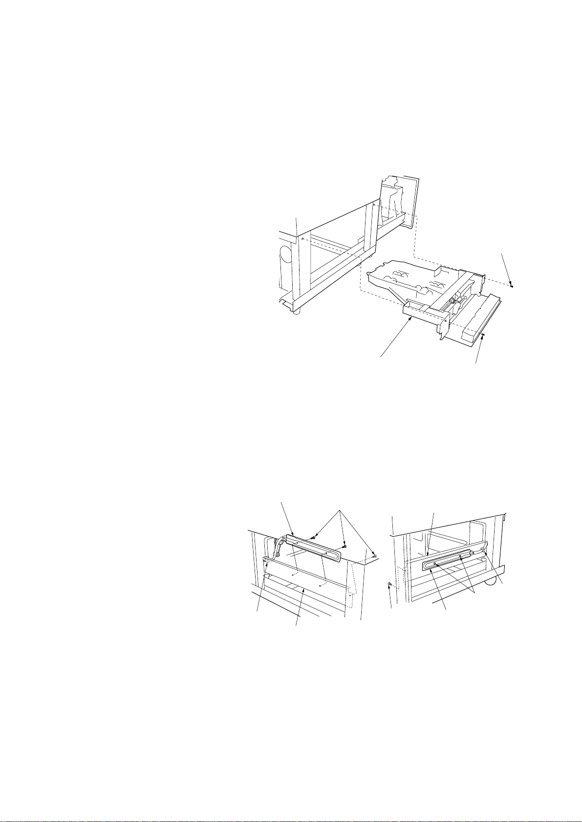
Procedure
1. Remove the two screws from each of the deck
right cover and deck left cover and then the
covers.
2. Remove the three screws holding the deck
rear cover and then the cover.
3. Open the large paper deck.
4. Remove the two screws holding the deck
paper conveying unit assembly and then the
assembly.
Screw
5. Fit the dehumidifier heaters to the dehumidifier
heater retainers using the two screws and wire
saddle for each.
6. Fit the dehumidifier heater retainers to the left
and right of the large paper deck using one
screw for each.
Dehumidifier heater
Wire saddle
Dehumidifier heater retainer
Deck paper conveying
unit assembly
Figure 1-2-2
Screws
Screw
Screw
Dehumidifier heater retainer
Wire
saddle
Screws
Dehumidifier heater
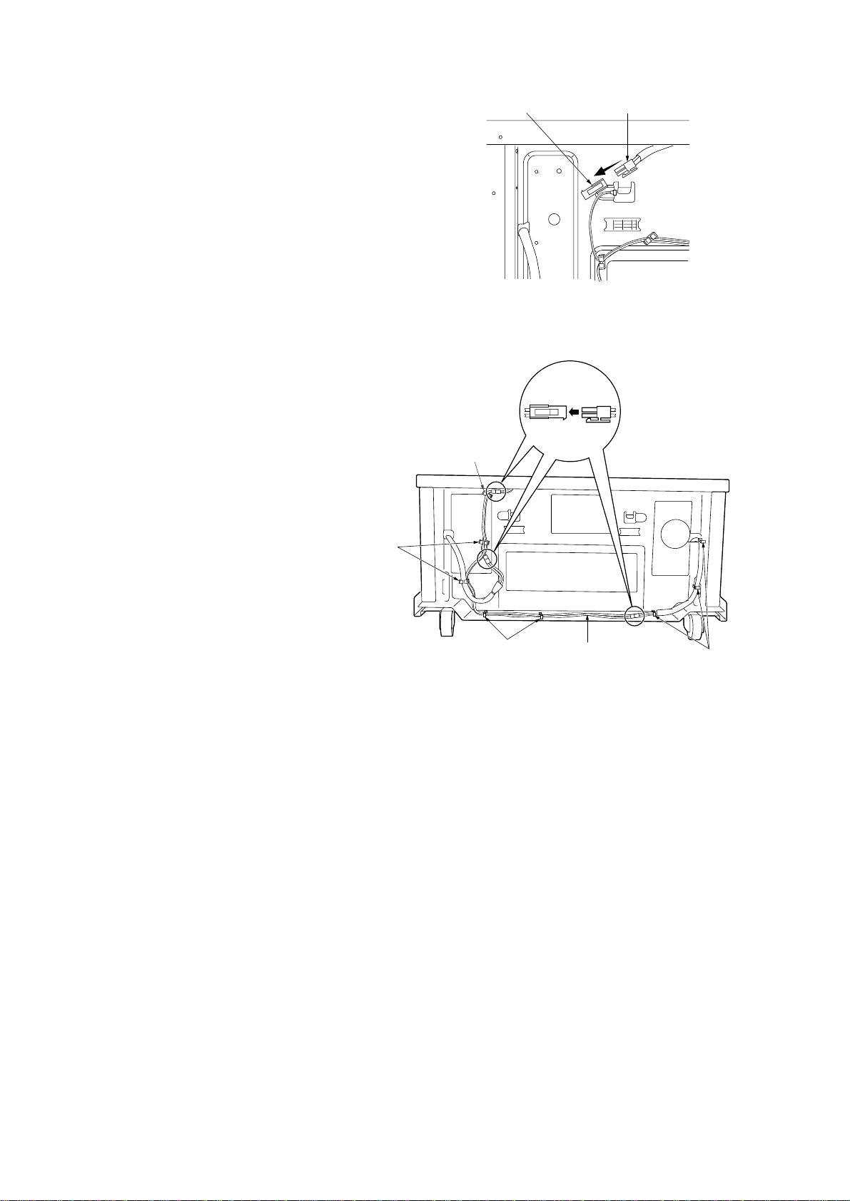
7. Pull the dehumidifier heater cable out to the
machine rear through the cable hole.
1-2-2
Machine rightMachine left
Figure 1-2-3
5FF
8. Detach the open connector from the connector
of the main harness on the machine rear.
9. Insert the dehumidifier heater connectors into
the relay wire connectors.
10. Insert the main harness connector into the
relay wire connector.
11. Tidy up the dehumidifier heater cable and relay
wire using the eight wire saddles and route the
cable and wire while clipping the wire saddles
into the holes in the rear frame.
12. Refit all removed parts.
Main harnessOpen connector
Figure 1-2-4
Wire saddle
Wire
saddles
Wire saddles
Relay wire
Figure 1-2-5
Wire saddles
1-2-3
5FF
1-3-1 Paper misfeed detection
(1) Paper misfeed indication
When a paper jam occurs, the machine immediately stops operation. The operation unit of the copier shows a jam message
and the jam location.
To reset the paper misfeed detection, open and close the deck side cover or the large paper deck to turn the side cover
switch or the deck open/closed safety switch off and on.
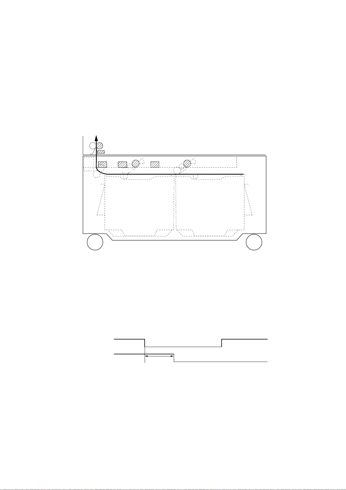
(2) Paper misfeed detection conditions
FCL3
FSW3
PPSENS1
PPSENS3
PPSENS2
PFCL1 PFCL2
Figure 1-3-1 Large paper deck
• No paper feed from large paper deck (jam code 12)
Feed switch 3 (FSW3) of the copier does not turn on within 650 ms of paper feed clutch 1 (PFCL1) turning on.
PFCL1
FSW3 (Copier)
650 ms
Timing chart 1-3-1
1-3-1

5FF
• Jam in large paper deck horizontal paper conveying section (jam code 15)
Paper path sensor 3 (PPSENS3) does not turn on within 290 ms of paper feed clutch 2 (PFCL2) turning on.
PFCL2
PPSENS3
290 ms
Timing chart 1-3-2
• Jam in large paper deck horizontal paper conveying section (jam code 16)
Paper path sensor 2 (PPSENS2) does not turn on within 310 ms of paper path sensor 3 (PPSENS3) turning on.
PPSENS3
PPSENS2
310 ms
Timing chart 1-3-3
• Jam in large paper deck horizontal paper conveying section (jam code 17)
Paper path sensor 1 (PPSENS1) does not turn on within 190 ms of paper path sensor 2 (PPSENS2) turning on.
PPSENS2
PPSENS1
190 ms
Timing chart 1-3-4
1-3-2
 Loading...