

Page 1

PF-730
SERVICE
MANUAL
Published in February 2011
843NJ110
3NJSM060
First Edition
Page 2

CAUTION
RISK OF EXPLOSION IF BATTERY IS REPLACED BY AN INCORRECT TYPE. DISPOSE
OF USED BATTERIES ACCORDING TO THE INSTRUCTIONS.
It may be illegal to dispose of this battery into the municipal waste stream. Check with your
local solid waste officials for details in your area for proper disposal.
ATTENTION
IL Y A UN RISQUE D’EXPLOSION SI LA BATTERIE EST REMPLACEE PAR UN MODELE
DE TYPE INCORRECT. METTRE AU REBUT LES BATTERIES UTILISEES SELON LES
INSTRUCTIONS DONNEES.
Il peut être illégal de jeter les batteries dans des eaux d’égout municipales. Vérifiez avec les
fonctionnaires municipaux de votre région pour les détails concernant des déchets solides
et une mise au rebut appropriée.
Page 3

Revision history
Revision Date Replaced pages Remarks
Page 4

This page is intentionally left blank.
Page 5

Safety precautions
This booklet provides safety warnings and precautions for our service personnel to ensure the safety of
their customers, their machines as well as themselves during maintenance activities. Service personnel
are advised to read this booklet carefully to familiarize themselves with the warnings and precautions
described here before engaging in maintenance activities.
Page 6
Safety warnings and precautions
Various symbols are used to protect our service personnel and customers from physical danger and
to prevent damage to their property. These symbols are described below:
DANGER: High risk of serious bodily injury or death may result from insufficient attention to or incorrect
compliance with warning messages using this symbol.
WARNING: Serious bodily injury or death may result from insufficient attention to or incorrect compliance
with warning messages using this symbol.
CAUTION: Bodily injury or damage to property may result from insufficient attention to or incorrect com-
pliance with warning messages using this symbol.
Symbols
The triangle ( ) symbol indicates a warning including danger and caution. The specific point of attention is
shown inside the symbol.
General warning. Warning of risk of electric shock.
Warning of high temperature.
indicates a prohibited action. The specific prohibition is shown inside the symbol.
General prohibited action. Disassembly prohibited.
indicates that action is required. The specific action required is shown inside the symbol.
General action required. Remove the power plug from the wall outlet.
Always ground the copier.
Page 7

1. Installation Precautions
WARNING
• Do not use a power supply with a voltage other than that specified. Avoid multiple connections to
one outlet: they may cause fire or electric shock. When using an extension cable, always check that
it is adequate for the rated current. .....................................................................................................
• Connect the ground wire to a suitable grounding point. Not grounding the copier may cause fire or
electric shock. Connecting the earth wire to an object not approved for the purpose may cause
explosion or electric shock. Never connect the ground cable to any of the following: gas pipes, lightning rods, ground cables for telephone lines and water pipes or faucets not approved by the proper
authorities. ..........................................................................................................................................
CAUTION:
• Do not place the copier on an infirm or angled surface: the copier may tip over, causing injury. .........
• Do not install the copier in a humid or dusty place. This may cause fire or electric shock. .................
• Do not install the copier near a radiator, heater, other heat source or near flammable material. This
may cause fire. ...................................................................................................................................
• Allow sufficient space around the copier to allow the ventilation grills to keep the machine as cool
as possible. Insufficient ventilation may cause heat buildup and poor copying performance. ............
• Always handle the machine by the correct locations when moving it. .................................................
• Always use anti-toppling and locking devices on copiers so equipped. Failure to do this may cause
the copier to move unexpectedly or topple, leading to injury. ..............................................................
• Avoid inhaling toner or developer excessively. Protect the eyes. If toner or developer is accidentally
ingested, drink a lot of water to dilute it in the stomach and obtain medical attention immediately.
If it gets into the eyes, rinse immediately with copious amounts of water and obtain medical atten-
tion. .....................................................................................................................................................
• Advice customers that they must always follow the safety warnings and precautions in the copier’s
instruction handbook. .........................................................................................................................
Page 8
2. Precautions for Maintenance
WARNING
• Always remove the power plug from the wall outlet before starting machine disassembly. ................
• Always follow the procedures for maintenance described in the service manual and other related
brochures. ..........................................................................................................................................
• Under no circumstances attempt to bypass or disable safety features including safety mechanisms
and protective circuits. ........................................................................................................................
• Always use parts having the correct specifications. ............................................................................
• Always use the thermostat or thermal fuse specified in the service manual or other related brochure
when replacing them. Using a piece of wire, for example, could lead to fire or other serious acci-
dent. ...................................................................................................................................................
• When the service manual or other serious brochure specifies a distance or gap for installation of a
part, always use the correct scale and measure carefully. ..................................................................
• Always check that the copier is correctly connected to an outlet with a ground connection. ...............
• Check that the power cable covering is free of damage. Check that the power plug is dust-free. If it
is dirty, clean it to remove the risk of fire or electric shock. .................................................................
• Never attempt to disassemble the optical unit in machines using lasers. Leaking laser light may
damage eyesight. ...............................................................................................................................
• Handle the charger sections with care. They are charged to high potentials and may cause electric
shock if handled improperly. ...............................................................................................................
CAUTION
• Wear safe clothing. If wearing loose clothing or accessories such as ties, make sure they are safely
secured so they will not be caught in rotating sections. ......................................................................
• Use utmost caution when working on a powered machine. Keep away from chains and belts. ..........
• Handle the fixing section with care to avoid burns as it can be extremely hot. ..................................
• Check that the fixing unit thermistor, heat and press rollers are clean. Dirt on them can cause
abnormally high temperatures. ...........................................................................................................
Page 9

• Do not remove the ozone filter, if any, from the copier except for routine replacement. ......................
• Do not pull on the AC power cord or connector wires on high-voltage components when removing
them; always hold the plug itself. ........................................................................................................
• Do not route the power cable where it may be stood on or trapped. If necessary, protect it with a
cable cover or other appropriate item. ................................................................................................
• Treat the ends of the wire carefully when installing a new charger wire to avoid electric leaks. ..........
• Remove toner completely from electronic components. .....................................................................
• Run wire harnesses carefully so that wires will not be trapped or damaged. ......................................
• After maintenance, always check that all the parts, screws, connectors and wires that were
removed, have been refitted correctly. Special attention should be paid to any forgotten connector,
trapped wire and missing screws. .......................................................................................................
• Check that all the caution labels that should be present on the machine according to the instruction
handbook are clean and not peeling. Replace with new ones if necessary. .......................................
• Handle greases and solvents with care by following the instructions below: ......................................
· Use only a small amount of solvent at a time, being careful not to spill. Wipe spills off completely.
· Ventilate the room well while using grease or solvents.
· Allow applied solvents to evaporate completely before refitting the covers or turning the power
switch on.
· Always wash hands afterwards.
• Never dispose of toner or toner bottles in fire. Toner may cause sparks when exposed directly to
fire in a furnace, etc. ...........................................................................................................................
• Should smoke be seen coming from the copier, remove the power plug from the wall outlet immedi-
ately. ...................................................................................................................................................
3. Miscellaneous
WARNING
• Never attempt to heat the drum or expose it to any organic solvents such as alcohol, other than the
specified refiner; it may generate toxic gas. ........................................................................................
• Keep the machine away from flammable liquids, gases, and aerosols. A fire or an electric shock
might occur. ........................................................................................................................................
Page 10

This page is intentionally left blank.
Page 11

CONTENTS
1-1 Specifications
1-1-1 Specifications ........................................................................................................................ 1-1-1
1-1-2 Parts names .......................................................................................................................... 1-1-2
1-1-3 Machine cross section ........................................................................................................... 1-1-3
1-2 Installation
1-2-1 Installation environment......................................................................................................... 1-2-1
1-2-2 Unpacking.............................................................................................................................. 1-2-2
(1) Precaution for unpacking.................................................................................................. 1-2-2
1-2-3 Unpacking.............................................................................................................................. 1-2-3
(1) Unpacking......................................................................................................................... 1-2-3
(2) Remove the tapes and pad .............................................................................................. 1-2-4
1-2-4 Installing the cassette heater (Option) ................................................................................... 1-2-6
1-3 Maintenance Mode
1-3-1 Maintenance mode ................................................................................................................ 1-3-1
(1) Executing a maintenance item ......................................................................................... 1-3-1
(2) Maintenance modes item list ............................................................................................ 1-3-2
(3) Contents of the maintenance mode items ........................................................................ 1-3-3
3NJ
1-4 Troubleshooting
1-4-1 Paper mis feed detection ....................................................................................................... 1-4-1
(1) Paper mis feed indication ................................................................................................. 1-4-1
(2) Paper mis feed detection condition .................................................................................. 1-4-1
1-4-2 Self-diagnostic function ......................................................................................................... 1-4-5
(1) Self-diagnostic function .................................................................................................... 1-4-5
(2) Self diagnostic codes........................................................................................................ 1-4-5
1-4-3 Electric problems ................................................................................................................... 1-4-8
1-4-4 Mechanical problems........................................................................................................... 1-4-10
1-5 Assembly and Disassembly
1-5-1 Precautions for assembly and disassembly........................................................................... 1-5-1
(1) Precautions....................................................................................................................... 1-5-1
1-5-2 Paper feed section................................................................................................................. 1-5-2
(1) Detaching and refitting the PF forwarding, PF paper feed and PF separation pulleys..... 1-5-2
1-5-3 PWBs..................................................................................................................................... 1-5-7
(1) Detaching and refitting the PF main PWB ........................................................................ 1-5-7
1-5-4 Driving section ....................................................................................................................... 1-5-9
(1) Detaching and refitting the PF Driving unit ....................................................................... 1-5-9
(2) Detaching and refitting the PF lift motors ....................................................................... 1-5-10
2-1 Mechanical Construction
2-1-1 Mechanical construction ........................................................................................................ 2-1-1
2-2 Electrical Parts Layout
2-2-1 Electrical parts layout ............................................................................................................ 2-2-1
(1) PWB and sensors............................................................................................................. 2-2-1
(2) Motors and others............................................................................................................. 2-2-3
Page 12

2-3 Operation of the PWBs
2-3-1 PF main PWB ........................................................................................................................ 2-3-1
2-4 Appendixes
2-4-1 Appendixes ............................................................................................................................ 2-4-7
(1) Wiring diagram ................................................................................................................. 2-4-7
3NJ
Page 13

1-1 Specifications
1-1-1 Specifications
Item Specifications
Paper weight 64 to 256g/m
Paper types Plain (80g/m2 or less), Thick (256g/m2 or less), recycled
3NJ
2
Paper size
A3, B4, A4, A4R, B5, B5R, A5R, Folio, Ledger, Legal, OficioII, 8.5 × 13.5",
Letter, LetterR, Excutive, StatementR, 8K, 16K, 16KR
Paper capacity 1000 sheets (500 sheets x 2) (80g/m
Dimensions
598 (W) x 315 (H) x 699.6 (D) mm
23
9/19” (W) x 12 3/8” (H) x 27 9/16” (D)
Weight Approx. 30kg / Approx. 66.1 lbs
Power source Electrically connected to the machine. (3.3 V DC, 24 V DC)
NOTE: These specifications are subject to change without notice.
2
)
1-1-1
Page 14
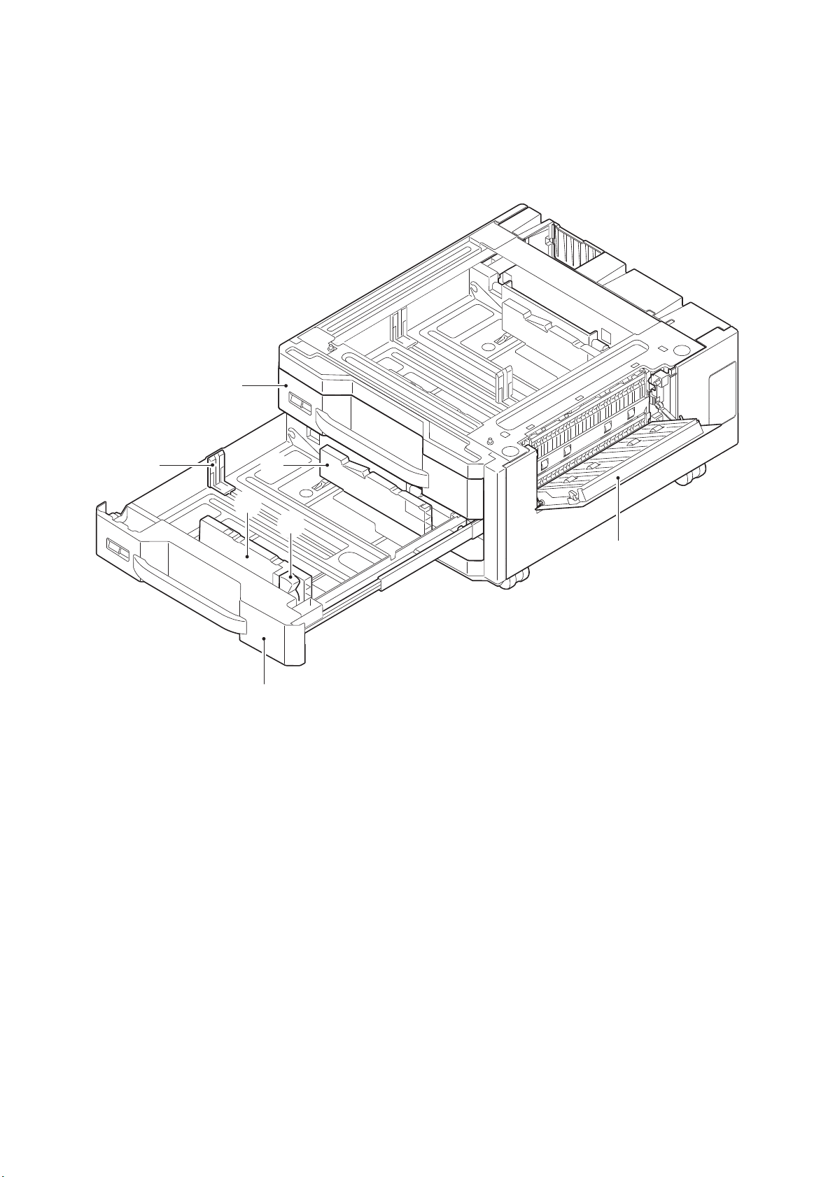
1-1-2 Parts names
1. PF paper conveying guide
2. Cassette 3
3. Cassette 4
4. PF paper size width guides
5. PF paper size width adjusting tab
6. PF paper size length guide
2
3NJ
6
4
4
5
1
3
Figure 1-1-1
1-1-2
Page 15
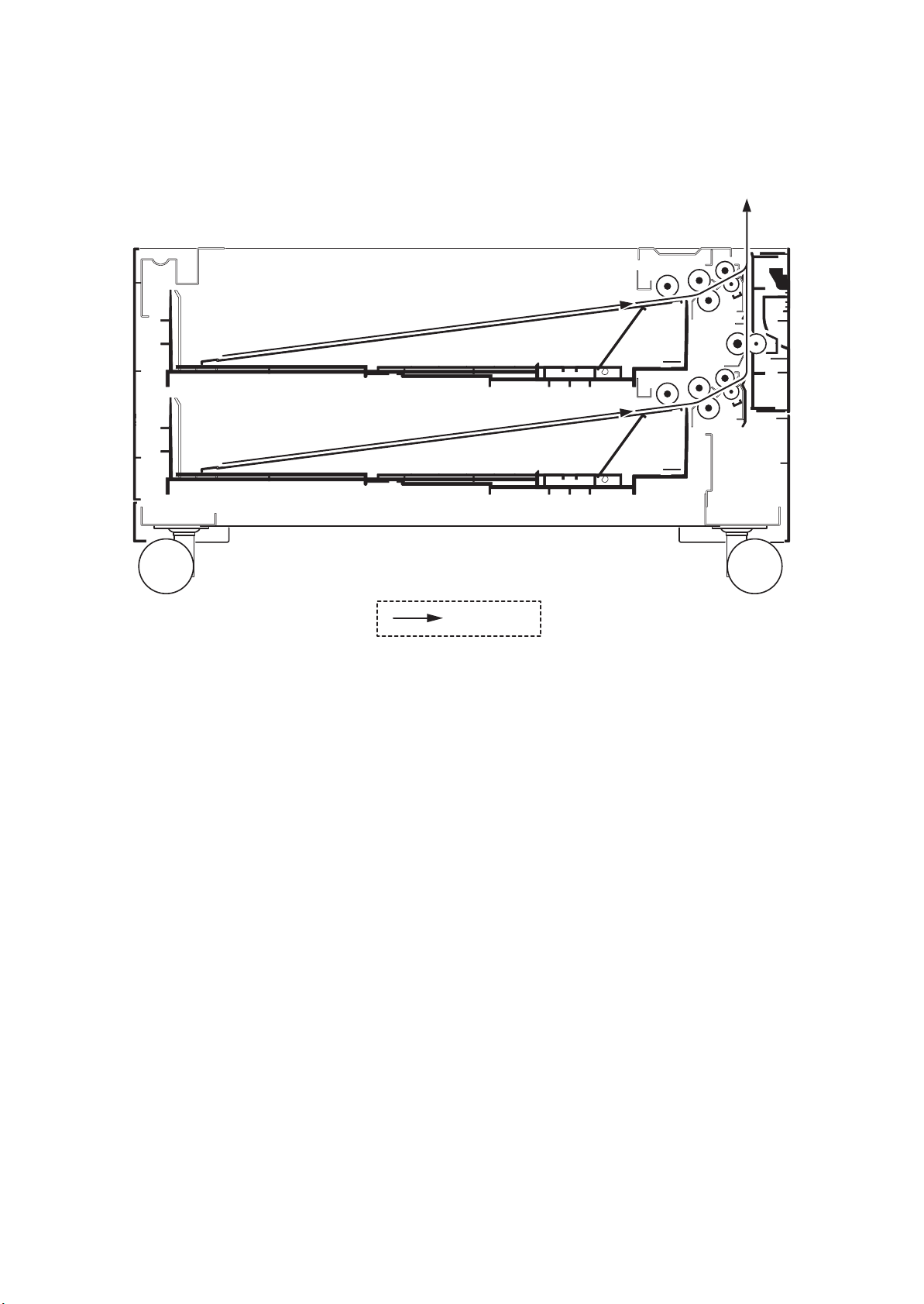
1-1-3 Machine cross section
3NJ
Paper path
Figure 1-1-2
1-1-3
Page 16

3NJ
This page is intentionally left blank.
1-1-4
Page 17

3NJ
1-2 Installation
1-2-1 Installation environment
Installation location (Be based on the machine establishment place.)
Avoid direct sunlight or bright lighting. Ensure that the photo conductor will not be exposed to direct sunlight or
other strong light when removing paper jams.
Avoid locations subject to high temperature and high humidity or low temperature and low humidity; an abrupt
change in the environmental temperature; and cool or hot, direct air.
Avoid places subject to dust and vibrations.
Choose a surface capable of supporting the weight of the machine.
Place the machine on a level surface (maximum allowance inclination: 1°).
Avoid air-borne substances that may adversely affect the machine or degrade the photo conductor, such as
mercury, acidic of alkaline vapors, inorganic gasses, NOx, SOx gases and chlorine-based organic solvents.
Select a well-ventilated location.
1-2-1
Page 18
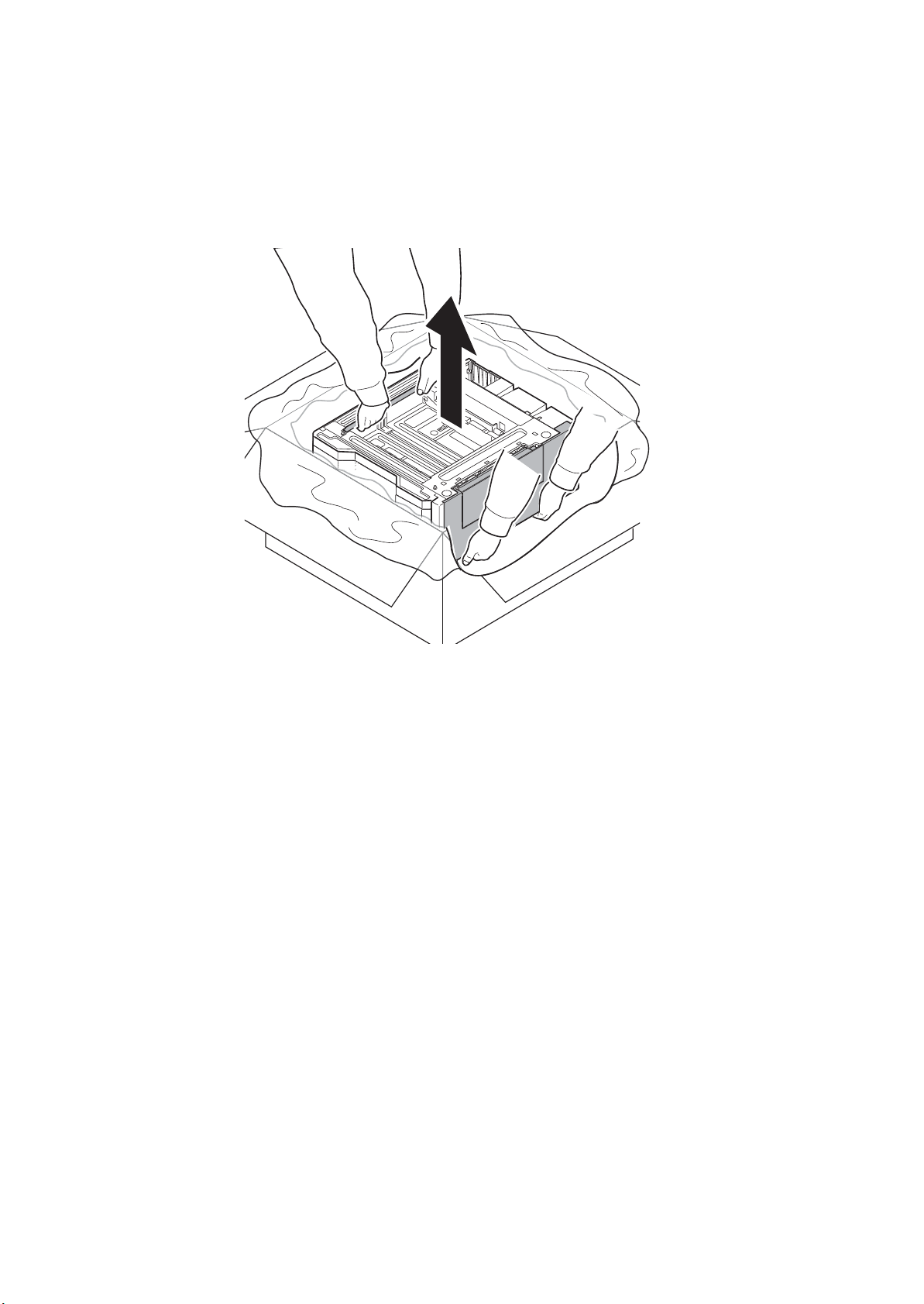
1-2-2 Unpacking
(1) Precaution for unpacking
Hold the positions shown in the figure and remove the paper feeder from the outer case.
3NJ
Figure 1-2-1
1-2-2
Page 19
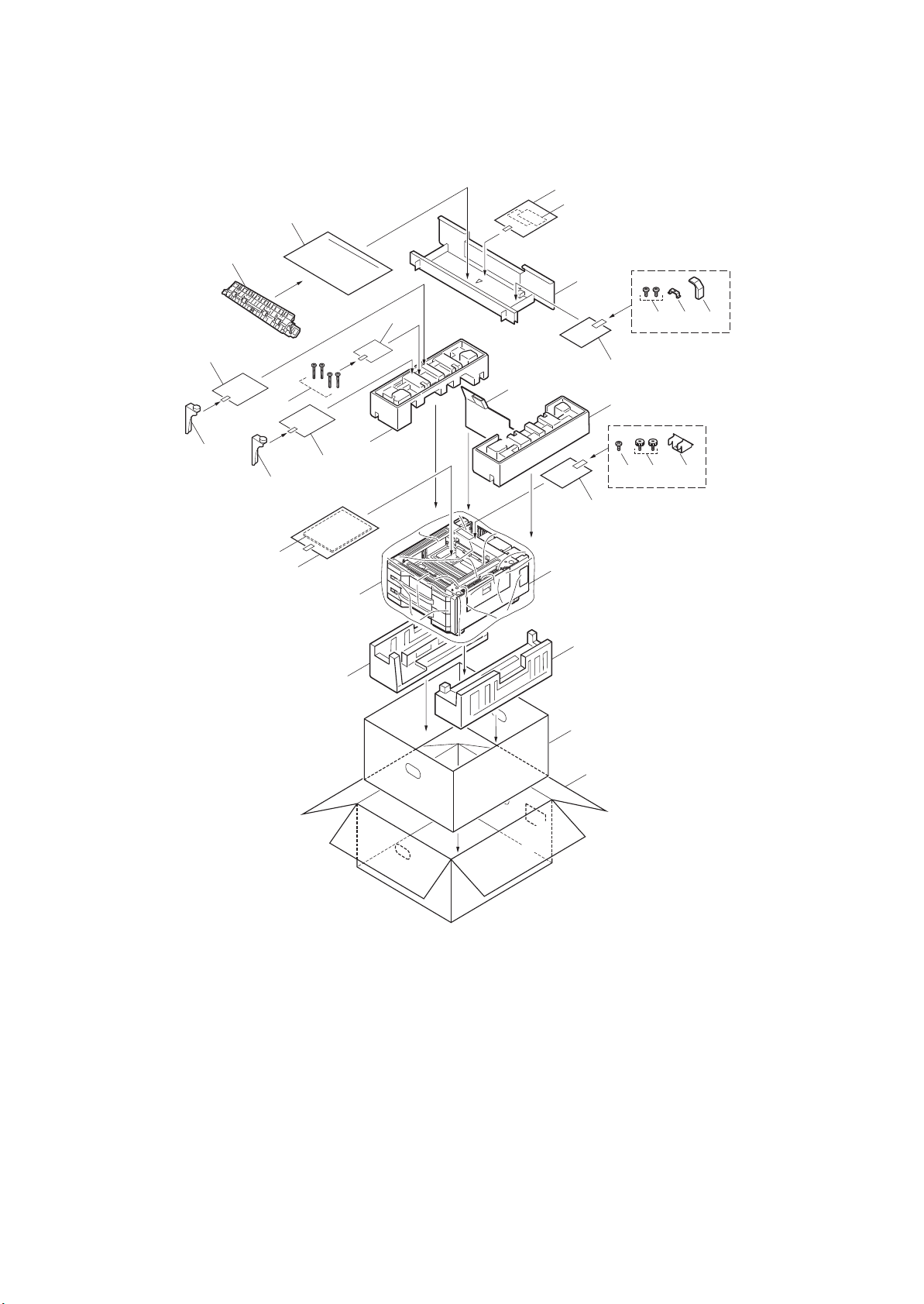
1-2-3 Unpacking
1. Paper feeder
2. Outer case
3. Inner case
4. Bottom left pad
5. Bottom right pad
6. Upper left pad
7. Upper right pad
8. Rear pad
9. Machine cover
10. Plastic bag
11. Installation guide
12. Accessory box
13. Plastic bag
14. Paper size plates
15. Plastic bag
16. Middle roller unit
17. Plastic bag
18. S tight screw M4 x 8B
19. Clamp
20. Wire cover
21. Plastic bag
22. S tight screws M4 x 8B
23. Pins
24. Retainer
25. Plastic bag
26. Supporting plate
27. Plastic bag
28. S tight screws M4 x 20B
(1) Unpacking
15
16
3NJ
13
14
12
25
26
11
28
26
10
25
27
18 19 20
17
8
7
6
6
22 23 24
21
1
9
5
4
3
Caution: Place the machine on a level surface. See the Installation Guide for installation.
Figure 1-2-2 Unpacking
1-2-3
2
Page 20
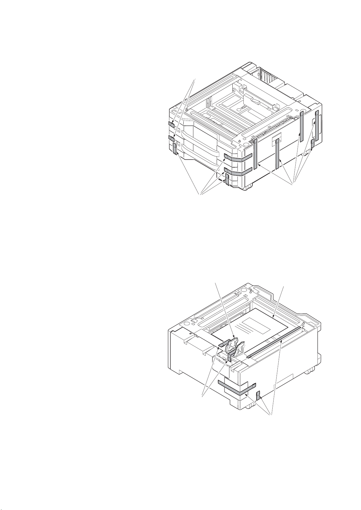
(2) Remove the tapes and pad
Procedure
1. Remove eleven tapes.
3NJ
Ta pe s
Ta pe s
Ta pe s
2. Remove five tapes and then remove the
retainer and the leaflet.
Retainer
Ta pe s
Figure 1-2-3
Leaflet
1-2-4
Ta pe s
Figure 1-2-4
Page 21
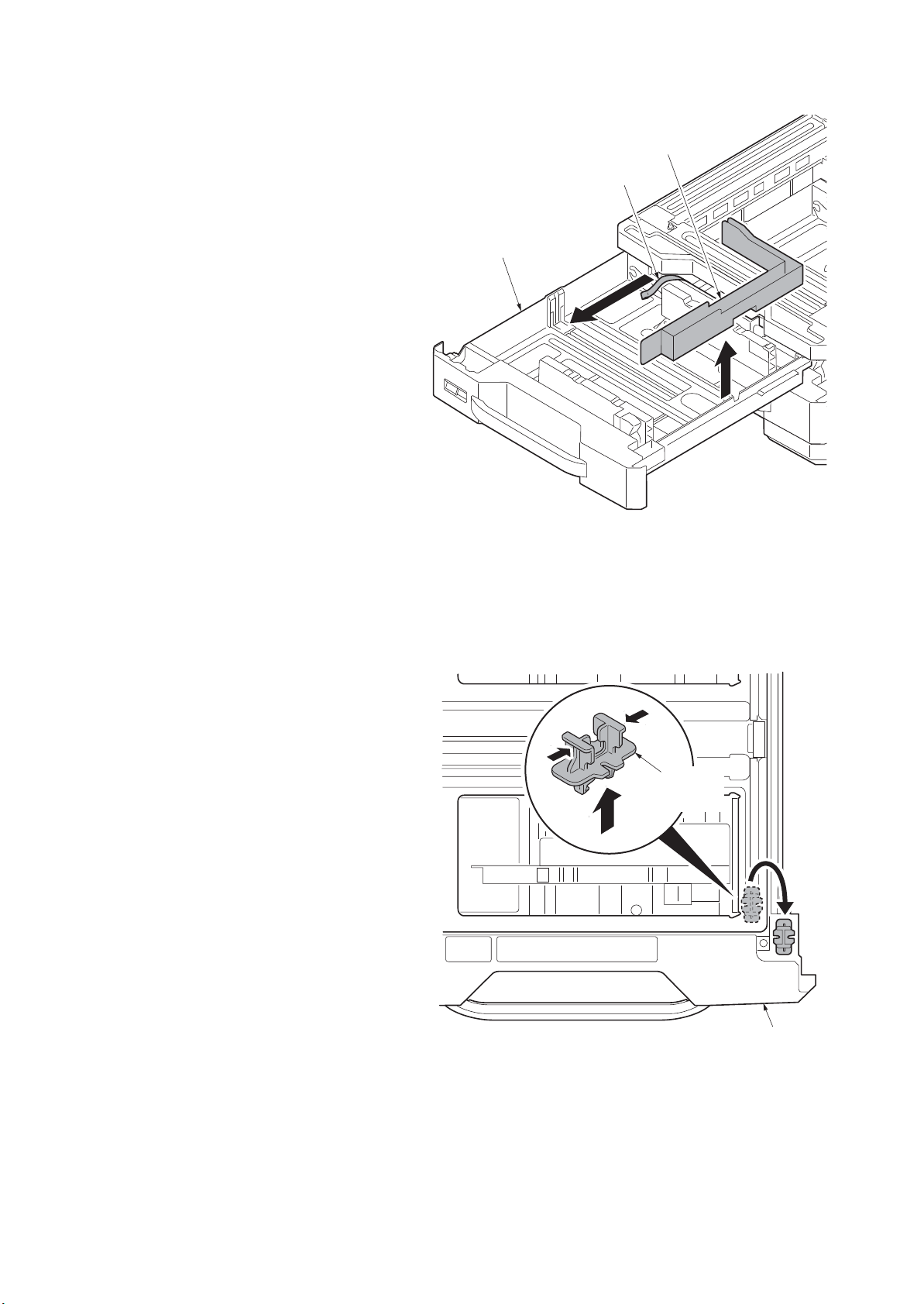
3NJ
3. Pull the upper cassette forward.
4. Remove the tape.
5. Remove the pad from cassette.
Pad
Ta pe
Cassette
Figure 1-2-5
6. Remove the lift plate stopper from
cassette and attach it to the storage
location.
* : When moveing the machine,attach the
lift plate in original position.
7. Gently push cassette back in.
8. Repeat steps 3 to 7 similarly for lower
cassette.
Lift plate
stopper
Cassette
Figure 1-2-6
1-2-5
Page 22
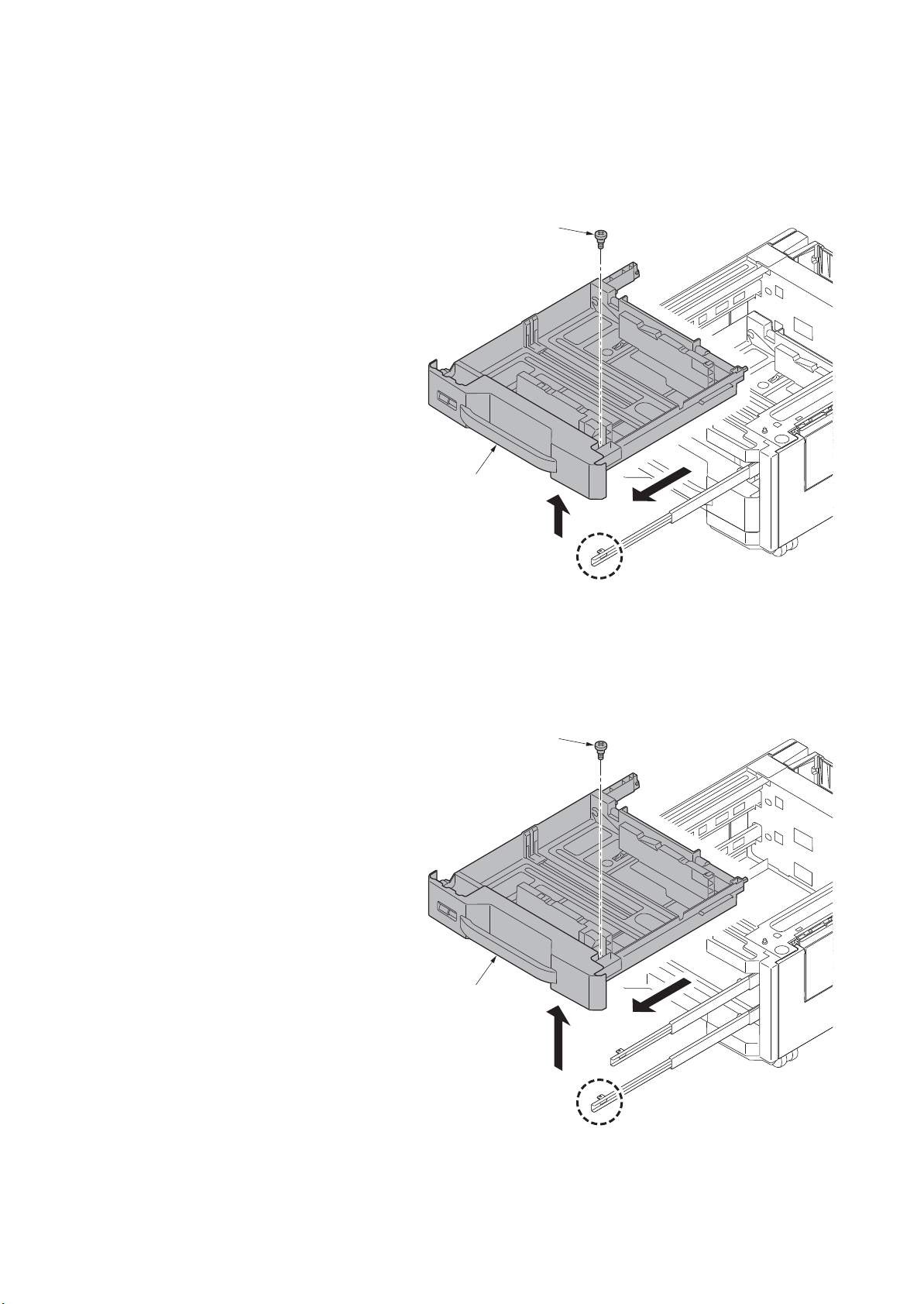
1-2-4 Installing the cassette heater (Option)
Procedure
1. Pull the cassette 3 forward.
2. Remove the pin and then remove the
cassette 3.
Cassette 3
Pin
3NJ
3. Pull the cassette 4 forward.
4. Remove the pin and then remove the
cassette 4.
Figure 1-2-7
Pin
Cassette 4
1-2-6
Figure 1-2-8
Page 23
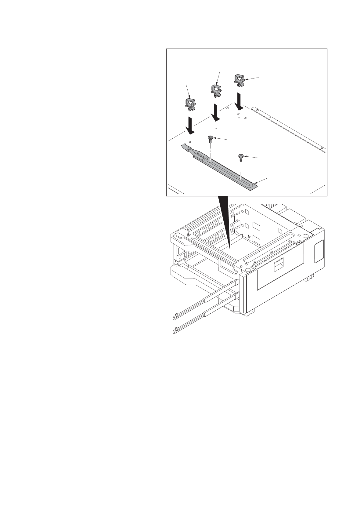
5. Install three wire saddles on the bottom
frame of the paper feeder.
6. Install the cassette heater by using two
screws.
Wire saddle
3NJ
Wire saddle
Wire saddle
Screw
Screw
Cassette heater
1-2-7
Figure 1-2-9
Page 24
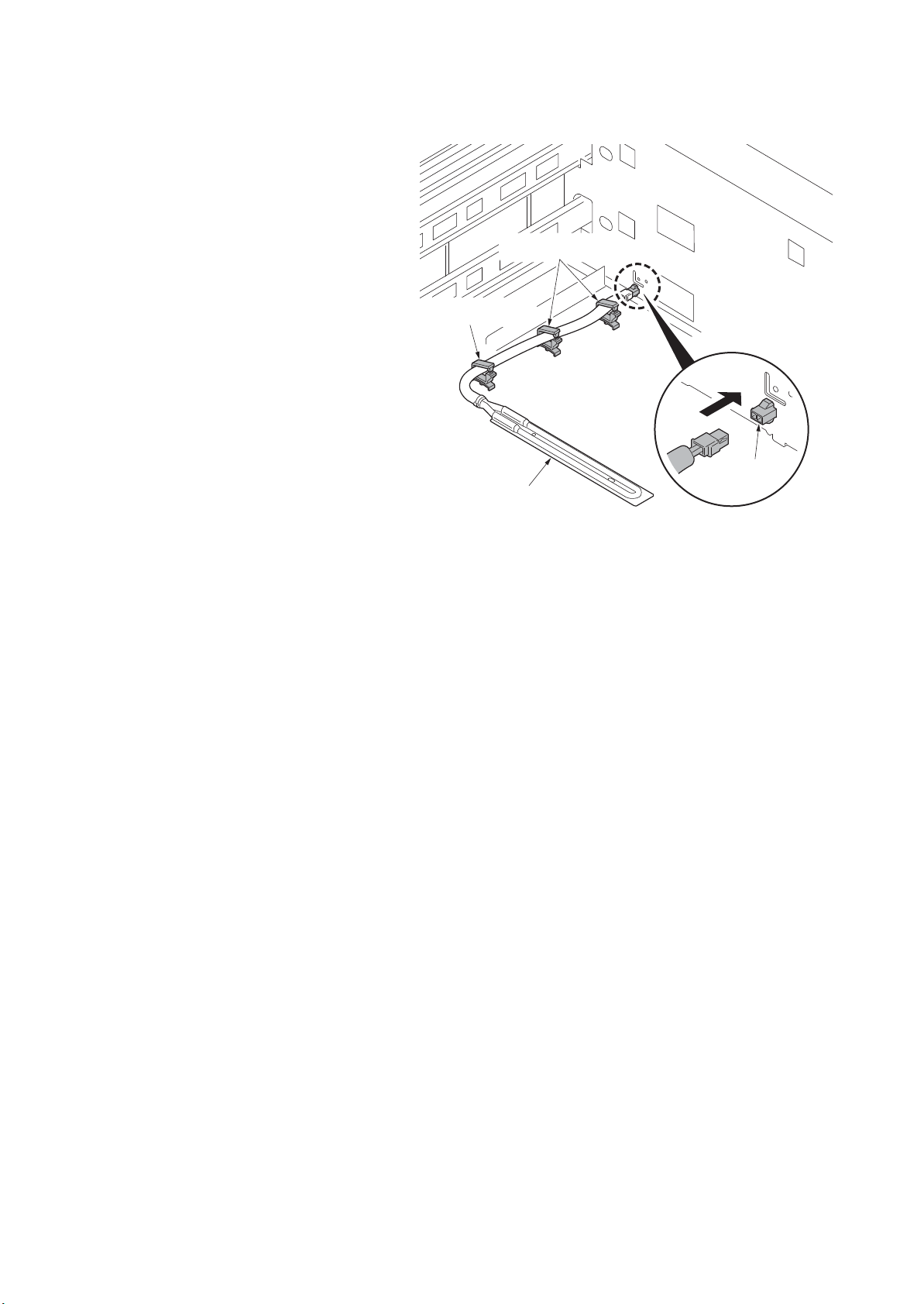
7. Connect the connector of the cassette
heater to the connector in the rear
frame of the paper feeder.
8. Pass through the wire of the cassette
heater to three wire saddles.
3NJ
Wire saddles
Wire saddle
Connector
Cassette heater
Figure 1-2-10
1-2-8
Page 25
1-3 Maintenance Mode
1-3-1 Maintenance mode
The machine is equipped with a maintenance function which can be used to maintain and service the
machine.
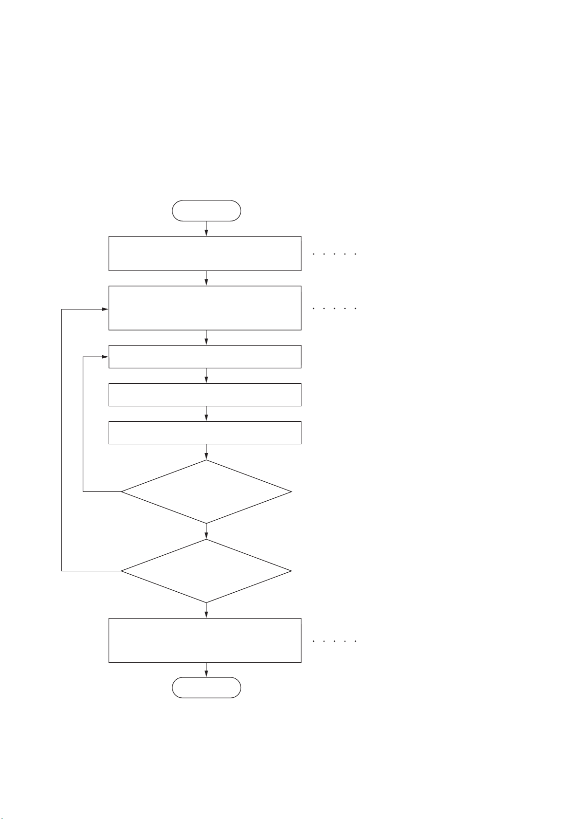
(1) Executing a maintenance item
Start
3NJ
Enter “10871087” using
the numeric keys.
Enter the maintenance item
number using the cursor
or numeric keys.
Press the start key.
The selected maintenance item is run.
Press the stop key.
Yes
Repeat the same
maintenance item?
up/down
keys
Maintenance mode is entered.
The maintenance item is selected.
Yes
No
Run another maintenance
item?
No
Enter 001 using the cursor
up/down keys or numeric keys
and press the start key.
End
Maintenance mode is exited.
1-3-1
Page 26

(2) Maintenance modes item list
3NJ
Section Item
No.
General U000 Outputting an own-status report -
U001 Exiting the maintenance mode -
U019 Displaying the ROM version -
Drive,
paper feed
and paper
conveying
system
Operation
panel and
support
equipment
Mode
setting
U034 Adjusting the print start timing
LSU Out Top 0/0/0/0/0/0/0/0/0/0/0/0
LSU Out Left 0/0/0/0/0/0/0/0/0
LSU Out Top B/W 0/0/0/0/0/0
LSU Out Top 3/4 0/0/0/0/0/0
U247 Setting the paper feed device -
U327 Setting the cassette heater control Off
U341 Specific paper feed location setting for printing
function
Content of maintenance item Initial setting
-
Others U901 Checking copy counts by paper feed locations -
1-3-2
Page 27

(3) Contents of the maintenance mode items
Display Output list
Maintenance List of the current settings of the maintenance modes
User Status Outputs the user status page
Service Status Outputs the service status page
Event Outputs the event log
Network Status Outputs the network status page
All Outputs the all reports
Display Description
Ready List of the current settings of the maintenance modes
Active Outputs the user status page
Complete Outputs the service status page
Error Outputs the event log
Item No. Description
U000 Outputting an own-status report
Description
Outputs lists of the current settings of the maintenance items, and paper jam and service call
occurrences. Outputs the event log or service status page. Also sends output data to the USB
memory.
Purpose
To check the current setting of the maintenance items, or paper jam or service call occurrences.
Before initializing or replacing the backup RAM, output a list of the current settings of the maintenance items to reenter the settings after initialization or replacement.
Method
1. Press the start key.
2. Select the item to be output using the cursor up/down keys.
3NJ
3. Press the start key. A list is output.
4. Press the start key. The interrupt print mode is entered and a list is output.
When A4/Letter paper is available, a report of this size is output. If not, specify the paper feed
location.
The output status is displayed.
1-3-3
Page 28

Item No. Description
Display Output list
Print Outputs the report
USB (Text) Sends output data to the USB memory (text type)
USB (HTML) Sends output data to the USB memory (HTML type)
U000 Method: Send to the USB memory
1. Press the power key on the operation panel, and after verifying the main power indicator has
gone off, switch off the main power switch.
2. Insert USB memory in USB memory slot.
3. Turn the main power switch on.
4. Enter the maintenance item.
5. Press the start key.
6. Select the item to be send.
7. Select [Text] or [HTML].
8. Press the start key.
Output will be sent to the USB memory.
Completion
Press the stop key. The screen for selecting a maintenance item No. is displayed.
3NJ
1-3-4
Page 29

Item No. Description
No. Items Description
(1) System version
(2) System date
(3) Engine soft version
(4) Engine boot version
U000 Event log
Event Log
MFP
(1)
Firmware version 2LC_2000.000.000 2010.10.27
(12)(8)
Paper Jam Log
#
Count.
16
9999999
15
8888888
14
7777777
13
6666666
12
5555555
11
4444444
10
3333333
9
2222222
8
1111111
7
999999
6
888888
5
777777
0501.01.08.01.01
4
666666
3
555555
2
444444
1
(9)
Service Call Log
#
Count.
8
1111111
7
999999
6
888888
5
777777
4
666666
3
555555
2
444444
1
(10)
Maintenance Log
# Count.
Log Data Nothing...
Unknown toner Log
(11)
#
Count.
5
1111111
4
999999
3
888888
2
777777
1
666666
Event Descriprions
0501.01.08.01.01
4002.01.08.01.01
0501.01.08.01.01
4002.01.08.01.01
0501.01.08.01.01
4002.01.08.01.01
0501.01.08.01.01
4002.01.08.01.01
0501.01.08.01.01
4002.01.08.01.01
0501.01.08.01.01
4002.01.08.01.01
0501.01.08.01.01
(a) (b) (c) (d) (e)
4002.01.08.01.01
0501.01.08.01.01
1
4002.01.08.01.01
Service Code
01.6000
01.2100
01.4000
01.6000
01.2100
01.4000
01.6000
1
01.2100
Item
Item
01.00
01.00
01.00
01.00
01.00
Counter Log
J0000:
(f) (g) (h)
J0001:
J0002:
J0003:
222
J0004:
J0005:
J0006:
J0007:
J0008:
J0009:
J0010:
J0012:
999
J0013:
J0014:
J0015:
J0016:
J0017:
J0018:
J0019:
J0020:
J0021:
J0022:
J0023:
J0024:
J0025:
J0026:
J0027:
J0028:
J0029:
J0030:
J0031:
J0032:
J0033:
J0034:
J0035:
J0036:
J0037:
J0038:
J0039:
J0040:
3NJ
(2)
27/Oct/2010 08:40
(6)(5)(4)(3)
[XXXXXXXX][XXXXXXXX][XXXXXXXX][XXXXXXXX]
J0041:
0
J0042:
1
J0043:
11
J0044:
J0045:
1
J0046:
1
J0047:
1
J0048:
1
J0049:
1
J0050:
1
1
1
1
1
1
1
1
1
1
1
1
1
1
1
1
1
1
1
1
1
1
1
1
1
1
1
1
1
1
1
C0000:
1
C0001:
1
C0002:
1
C0003:
1
C0004:
1
C0005:
1
C0006:
1
C0007:
1
C0008:
1
C0009:
C0010:
C0011:
C0012:
C0013:
C0014:
C0015:
C0016:
C0017:
C0018:
C0019:
C0020:
C0021:
C0022:
C0023:
10
11
12
13
14
15
16
17
18
19
20
21
22
23
0
T00:
T01:
T02:
T03:
T04:
T05:
10
20
30
40
50
999
1
2
3
4
5
6
7
8
9
Detail of event log
Figure 1-3-1
1-3-5
(7)
[XXXXXXXXXXXXXXXX]
Page 30

Item No. Description
No. Items Description
(5) Controller BROM version
(6) Operation panel mask version
(7) Machine serial number
(8) Paper Jam
Log
# Count. Event
Remembers 1 to 16 of
occurrence. If the occurrence of the previous
paper jam is less than
16, all of the paper jams
are logged. When the
occurrence excesseds
16, the oldest occurrence is removed.
The total page count
at the time of the
paper jam.
Log code (hexadecimal, 5 categories)
(a) Cause of a paper
jam
(b) Paper source
(c) Paper size
(d) Paper type
(e) Paper eject
(a) Cause of paper jam (Hexadecimal)
For details on the case of paper jam, refer to Paper Mis feed Detection.
(P.1-4-1)
(b) Detail of paper source (Hexadecimal)
00: MP tray
01: Cassette 1
02: Cassette 2
03: Cassette 3 (paper feeder/large capacity feeder)
04: Cassette 4 (paper feeder/large capacity feeder)
05: Cassette 5 (side feeder/SMT paper feeder)
06: Cassette 6 (side paper feeder/side large capacity feeder)
07: Cassette 7 (side paper feeder/side large capacity feeder)
08 to 09: Reserved
(c) Detail of paper size (Hexadecimal)
00: (Not specified)
01: Monarch
02: Business
03: International DL
04: International C5
05: Executive
06: Letter-R
86: Letter-E
07: Legal
08: A4R
88: A4E
09: B5R
89: B5E
0A: A3
0B: B4
0C: Ledger
0D: A5R
0E: A6
0F: B6
10: Commercial #9
11: Commercial #6
12: ISO B5
13: Custom size
1E: C4
1F: Postcard
20: Reply-paid post-
card
21: Oficio II
22: Special 1
23: Special 2
24: A3 wide
25: Ledger wide
26: Full bleed paper
(12 x 8)
27: 8K
28: 16K-R
A8: 16K-E
32: Statement-R
B2: Statement-E
33: Folio
34: Western type 2
35: Western type 4
U000 Detail of event log
3NJ
1-3-6
Page 31

Item No. Description
No. Items Description
(8)
cont.
Paper Jam
Log
(d) Detail of paper type (Hexadecimal)
01: Plain
02: Transparency
03: Preprinted
04: Labels
05: Bond
06: Recycled
07: Vellum
08: Rough
09: Letterhead
0A: Color
0B: Prepunched
0C: Envelope
0D: Cardstock
0E: Coated
0F: 2nd side
10: Media 16
11: High quality
15: Custom 1
16: Custom 2
17: Custom 3
18: Custom 4
19: Custom 5
1A: Custom 6
1B: Custom 7
1C: Custom 8
(e) Detail of paper eject location (Hexadecimal)
01: Face down (FD)
02: Face up (FU)/1000-sheet finisher face up (FU)/
4000-sheet finisher left sub tray (FU)
03: 1000-sheet finisher face down (FD)
4000-sheet finisher main tray (FD)
05: Job separator tray
06: 4000-sheet finisher right sub tray (FU)
07: 4000-sheet finisher left sub tray (FD)
09: 4000-sheet finisher right sub tray (FD)
0A: Center-folding unit tray
0B: Mailbox tray 1 (FD)
0C: Mailbox tray 1 (FU)
15: Mailbox tray 2 (FD)
16: Mailbox tray 2 (FU)
1F: Mailbox tray 3 (FD)
20: Mailbox tray 3 (FU)
29: Mailbox tray 4 (FD)
2A: Mailbox tray 4 (FU)
33: Mailbox tray 5 (FD)
34: Mailbox tray 5 (FU)
3D: Mailbox tray 6 (FD)
3E: Mailbox tray 6 (FU)
47: Mailbox tray 7 (FD)
48: Mailbox tray 7 (FU)
04/0D/0E: Reserved
U000
3NJ
1-3-7
Page 32

Item No. Description
No. Items Description
(9) Service Call
Log
# Count. Service Code
Remembers 1 to 8
of occurrence of self
diagnostics error. If
the occurrence of
the previous diagnostics error is less
than 8, all of the
diagnostics errors
are logged.
The total page
count at the time of
the self diagnostics
error.
Self diagnostic error code
(See page 1-4-5)
Example:
01.6000
01: Self diagnostic error
6000: Self diagnostic error
code number
(10) Maintenance
Log
# Count. Item
Remembers 1 to 8
of occurrence of
replacement. If the
occurrence of the
previous replacement of toner container is less than 8,
all of the occurrences of replacement are logged.
The total page
count at the time of
the replacement of
the toner container.
Code of maintenance
replacing item
(1 byte, 2 categories)
First byte (Replacing item)
01: Toner container
Second byte
(Type of replacing item)
00: Black
01: Cyan
02: Magenta
03: Yellow
First byte (Replacing item)
02: Maintenance kit
Second byte
(Type of replacing item)
01: MK-8305A/8505A
02: MK-8305B/8505B
03: MK-8305C/8505C
(11) Unknown
Toner Log
# Count. Item
Remembers 1 to 5
of occurrence of
unknown toner
detection. If the
occurrence of the
previous unknown
toner detection is
less than 5, all of the
unknown toner
detection are
logged.
The total page
count at the time of
the toner empty
error with using an
unknown toner
container.
Unknown toner log code
(1 byte, 2 categories)
First byte
01: Toner container (Fixed)
Second byte
00: Black
01: Cyan
02: Magenta
03: Yellow
U000
3NJ
1-3-8
Page 33

Item No. Description
No. Items Description
(12) Counter Log
Comprised of
three log counters including
paper jams, self
diagnostics
errors, and
replacement of
the toner container.
(f) Paper jam (g) Self diagnostic
error
(h) Maintenance item
replacing
Indicates the log
counter of paper
jams depending on
location.
Refer to Paper Jam
Log.
All instances including those are not
occurred are displayed.
Indicates the log
counter of self diagnostics errors
depending on
cause.
Example:
C6000: 4
Self diagnostics
error 6000 has happened four times.
Indicates the log counter depending on the
maintenance item for
maintenance.
T: Toner container
00: Black
01: Cyan
02: Magenta
03: Yellow
M: Maintenance kit
01: MK-8305A/8505A
02: MK-8305B/8505B
03: MK-8305C/8505C
Example:
T00: 1
The toner container has
been replaced once.
U000
3NJ
1-3-9
Page 34

Item No. Description
U000 Service status page (1)
3NJ
Service Status Page
MFP
(1)
Firmware version 2LC_2000.000.000 2010.10.27
Controller Information
Memory status
(7)
Total Size
Time
(8)
Local Time Zone
(9)
Date and Time
(10)
Time Server
Installed Options
Document Processor
(11)
Paper feeder
(12)
Finisher
(13)
Job Separator
(14)
Document Guaed (A)
(15)
Card Authentication Kit (B)
(16)
Internet FAX Kit (A)
(17)
Security Kit (E)
(18)
Data Security Kit (E) Software Type I
UG-34
(19)
Print Coverage
(20)
Average(%)
(21)
To ta l
K: 1.10
C: 2.20
M: 3.30
Y: 4.40
(22)
Copy
K: 1.10
C: 2.20
M: 3.30
Y: 4.40
(23)
Printer
K: 1.10
C: 2.20
M: 3.30
Y: 4.40
(24)
FAX
K: 1.10
(25)
Period
(26)
Last Page K/C/M/Y(%)
/ Usage Page(A4/Letter Conversion)
/ 1111111 . 11
/ 2222222.22
/ 3333333.33
/ 4444444.44
/ 1111111 . 11
/ 2222222.22
/ 3333333.33
/ 4444444.44
/ 1111111 . 11
/ 2222222.22
/ 3333333.33
/ 4444444.44
/ 1111111 . 11
(27/10/2010 - 03/11/2010 08:40)
1.00 / 2.22 / 3.33 / 4.44
2.0 GB
+01:00 Amsterdam
27/10/2010 12:00
10.183.53.13
Installed
Cassette
1000-Finisher
Installed
Installed
Installed
Installed
Installed
Installed
(32)
FRPO Status
Default Pattern Switch
Default Font Number
.
.
.
.
.
.
.
.
.
.
.
.
.
.
.
.
.
.
.
.
.
.
e-MPS error control
(2)
27/10/2010 12:00
(3) (4) (5)
[XXXXXXXX] [XXXXXXXX] [XXXXXXXX]
B8
C5*1000+C2*100+C3
Y6
0
00000
0
(27)
FAX Information Slot1/Slot2
(28)
Rings (Normal)
(29)
Rings (FAX/TEL)
(30)
Rings (TAD)
(31)
Option DIMM Size
3
3
3
16 MB
1
Figure 1-3-2
1-3-10
(6)
[XXXXXXXXXXXXXXXX]
Page 35

Item No. Description
U000 Service status page (2)
Service Status Page
MFP
3NJ
27/10/2010 12:00
Firmware version 2LC_2000.000.000 2010.10.27
Engine Information
(33)
NVRAM Version
(34)
Scanner Version
(35)
FAX Slot1
FAX BOOT Version
FAX APL Version
FAX IPL Version
(36)
MAC Address
1/2
(41)
(42)
(43)
(44)
(58)
(59)
(64)
(65)
(66)
(67)
(68)
(69)
(70)
(71)
(72)
(73)
(39) (40)
100/100
0/0/0/0/0/0/0/0
0000000/0000000/0000000/0000000/0000000/0000000/0000000/
0000000/0000000/0000000/0000000/0000000/0000000/0000000/0000000/0000000/0000000/0000000/
F00/U00/0/0/0/0/30/30/70/70/abcde/1/0
0000/0000/0000/0000/0000/0000/0000/0000/0000/0000/0000/0000/0000/0000/0000/
0000/0000/0000/0000/0000/0000/0000/0000/0000/0000/
0000/0100/0500/1000/0000/0100/0500/1000/0000/0100/0500/1000/0000/0100/0500/1000/
0000/0100/0500/1000/0000/0100/0500/1000/0000/0100/0500/1000/0000/0100/0500/1000/
00000000000000000000000000000000/0000000000000000000000000000000000000000/0000000000/
0000000000000000/0000000000000000/0000000000000000/0000000000000000/0000000000000000/
0000000000000000/0000000000000000/0000000000000000/0000000000000000/0000000000000000/
0000000000000000/0000000000000000/0000000000000000/0000000000000000/0000000000000000/
0000000000000000/0000000000000000/0000000000000000/0000000000000000/0000000000000000/
0000000000000000/0000000000000000/0000000000000000/0000000000000000/
0000000000000000/0000000000000000/0000000000000000/0000000000000000/0000000000000000/
0000000000000000/0000000000000000/0000000000000000/0000000000000000/0000000000000000/
0000000000000000/0000000000000000/0000000000000000/0000000000000000/0000000000000000/
0000000000000000/0000000000000000/0000000000000000/0000000000000000/0000000000000000/
12345678/11223344/00001234abcd567800001234abcd5678/01234567890123456789012345678901/0008/00/07
12345678/11223344/00001234abcd567800001234abcd5678/01234567890123456789012345678901/0008/00/07
12345678/11223344/00001234abcd567800001234abcd5678/01234567890123456789012345678901/0008/00/07
12345678/11223344/00001234abcd567800001234abcd5678/01234567890123456789012345678901/0008/00/07
XXXXXXXX
[ABCDEFGHIJ][ABCDEFGHIJ]
00070107FE/0700FE00FE/00FE000100/0000000000/0000000000/0000000000/00000A010A/0A0A0A3200/
0008000000/080000001D/0096009B00/9B009BFFFB/0082000000/000000001F/0000002C00/0000000000/
0000000000/0000000000/0000000000/0000000000/0000000000/0000000000/0000000000/0000010105/
010A000000/0000000000/003C4C0100/0000000087/A28000363C/8000676B83/0000000000/0000000000/
0000000000/0000000000/0000000000/0000000000/0000000000/0000000000/0000000000/0000000005/
0000000000/0000000000/0000000000/0000000000/0000000000/000000024E/
ABCDEFGHIJ/ABCDEFGHIJ/ABCDEFGHIJ/ABCDEFGHIJ/
_1F31225_1F31225
2LC_1200.001.089
2LC_5000.001.001
2LC_5100.001.001
2LC_5200.001.001
00:C0:EE:D0:01:0D
(45) (46) (47) (48) (49) (50) (51) (52) (53) (54) (55) (56) (57)
[XXXXXXXX] [XXXXXXXX] [XXXXXXXX]
Send Information
(37)
Date and Time
(38)
Address
10/10/27
(60) (61) (62)
2
Figure 1-3-3
1-3-11
[XXXXXXXXXXXXXXXX]
Page 36

Item No. Description
No. Description Supplement
(1) Firmware version -
(2) System date -
(3) Engine soft version -
(4) Engine boot version -
(5) Operation panel mask version -
(6) Machine serial number -
(7) Total memory size -
(8) Local time zone -
(9) Report output date Day/Month/Year hour:minute
(10) NTP server name -
(11) Presence or absence of the
document processor
Installed/Not Installed
(12) Presence or absence of the
paper feeder
Paper feeder/Large capacity feeder/Not Installed
(13) Presence or absence of the
finisher
1000-sheet finisher/4000-sheet finisher/
Not Installed
(14) Presence or absence of the
job separator
Installed/Not Installed
(15) Presence or absence of the
printed document guard kit
Installed/Not Installed
(16) Presence or absence of the IC
card authentication kit
Installed/Not Installed/Trial
(17) Presence or absence of the
internet fax kit
Installed/Not Installed
(18) Presence or absence of the
data security kit
Installed/Not Installed
(19) Presence or absence of the
UG-34
Installed/Not Installed
(20) Page of relation to the A4/Letter -
(21) Average coverage for total Black/Cyan/Magenta/Yellow
(22) Average coverage for copy Black/Cyan/Magenta/Yellow
(23) Average coverage for printer Black/Cyan/Magenta/Yellow
(24) Average coverage for fax Black/Cyan/Magenta/Yellow
(25) Cleared date and output date -
(26) Coverage on the final output
page
-
U000 Detail of service status page
3NJ
1-3-12
Page 37

Item No. Description
No. Description Supplement
(27) Fax kit information This item is printed only when the fax kit is
installed.
(28) Number of rings 0 to 15
(29) Number of rings before auto-
matic switching
0 to 15
(30) Number of rings before connect-
ing to answering machine
0 to 15
(31) Optional DIMM size -
(32) FRPO setting -
(33) NV RAM version _ 1F3 1225 _ 1F3 1225
(a) (b) (c) (d) (e) (f)
(a) Consistency of the present software version
and the database
_ (underscore): OK
* (Asterisk): NG
(b) Database version
(c) The oldest time stamp of database version
(d) Consistency of the present software version
and the ME firmware version
_ (underscore): OK
* (Asterisk): NG
(e) ME firmware version
(f) The oldest time stamp of the ME database ver-
sion
Normal if (a) and (d) are underscored, and (b) and
(e) are identical with (c) and (f).
(34) Scanner firmware version -
(35) Fax firmware version This item is printed only when the fax kit is
installed.
(36) Mac address -
(37) The last sent date and time -
(38) Transmission address -
(39) Destination information -
(40) Area information -
(41) Margin settings Top margin/Left margin
(42) Margin/Page length/Page width
settings
Top margin integer part/Top margin decimal part/
Left margin integer part/Left margin decimal part/
Page length integer part/Page length decimal part/
Page width integer part/Page width decimal part
U000
3NJ
1-3-13
Page 38

Item No. Description
No. Description Supplement
(43) Life counter (The first line) Machine life/MP tray/Cassette 1/Cassette 2/
Cassette 3/Cassette 4/Duplex
(44)
Life counter (The second line) Drum unit K/Drum unit C/Drum unit M/Drum unit Y/
Transfer belt unit/Developer unit K/
Developer unit C/Developer unit M/
Developer unit Y/Maintenance kit A/
Maintenance kit B
(45) Panel lock information 0: OFF/1: Partial lock/2: Full lock
(46) USB information U00: Not installed/U01: Full speed/U02: Hi speed
(47) Paper handling information 0: Paper source unit select/1: Paper source unit
(48) Color printing double count
mode
0: All single counts
1: A3, Single count, Less than 420 mm (length)
2: Legal, Single count, 356 mm or less (length)
3: Folio, Single count, Less than 330 mm (length)
(49) Black and white printing double
count mode
0: All single counts
1: A3, Single count, Less than 420 mm (length)
2: Legal, Single count, 356 mm or less (length)
3: Folio, Single count, Less than 330 mm (length)
(50) Billing counting timing -
(51) Temperature (machine inside) -
(52) Temperature (machine outside) -
(53) Relative temperature
(machine outside)
-
(54) Absolute temperature
(machine outside)
-
(55) Fixed assets number -
(56) Job end judgment time-out time -
(57) Job end detection mode -
(58) Media type attributes
1 to 28 (Not used: 18, 19, 20)
Weight settings Fuser settings
0: Light 0: High
1: Normal 1 1: Middle
2: Normal 2 2: Low
3: Normal 3 3: Vellum
4: Heavy 1 Duplex settings
5: Heavy 2 0: Disable
6: Heavy 3 1: Enable
7: Extra Heavy
U000
3NJ
1-3-14
Page 39

Item No. Description
No. Description Supplement
(59) Calibration information Black/Cyan/Magenta/Yellow
(60) Calibration information -
(61) Calibration information -
(62) Calibration information -
(63) Calibration information -
(64) Calibration information -
(65) Calibration information -
(66) Calibration information -
(67) Calibration information -
(68) Calibration information -
(69) RFID information -
(70) RFID reader/writer version infor-
mation
-
(71) Color table version -
(72) Color table 2 version -
(73) Maintenance information -
Code conversion
ABCDEFGH I J
0123456789
U000
3NJ
U001 Exiting the maintenance mode
Completion
Press the stop key. The screen for selecting a maintenance item No. is displayed.
Description
Exits the maintenance mode and returns to the normal copy mode.
Purpose
To exit the maintenance mode.
Method
1. Press the start key. The normal copy mode is entered.
1-3-15
Page 40

Item No. Description
Display Description
Main Main ROM
MMI Operation ROM
Browser Browser ROM
Engine Engine ROM
Engine Boot Engine booting
Scanner Scanner ROM
Scanner Boot Scanner booting
RFID RFID ROM
IH CPU IH CPU ROM
IH CPU Boot IH CPU booting
Motor CPU Motor CPU ROM
Motor CPU Boot Motor CPU booting
Dictionary -
Option Language Optional language ROM
PDF1.7 Resource PDF1.7 resource ROM
Solution Framework Framework ROM
FMU FMU ROM
Weekly Timer Weekly Timer ROM
Color Table1(Copy) Color table 1 (copy) ROM
Color Table2(Copy) Color table 2 (copy) ROM
Color Table1(Prn) Color table 1 (printer) ROM
Color Table2(Prn) Color table 2 (printer) ROM
DP Document processor ROM
DP Boot Document processor booting
PF1 Paper feeder / Large capacity feeder ROM
PF1 Boot Paper feeder / Large capacity feeder booting
Side PF SMT paper feeder /Side feeder ROM
Side PF Boot SMT paper feeder /Side feeder booting
U019 Displaying the ROM version
Description
Displays the part number of the ROM fitted to each PWB.
Purpose
To check the part number or to decide, if the newest version of ROM is installed.
Method
1. Press the start key. The ROM version are displayed.
2. Change the screen using the cursor up/down keys.
3NJ
1-3-16
Page 41

Item No. Description
Display Description
PF2 Side paper feeder / Side large capacity feeder ROM
PF2 Boot Side paper feeder / Side large capacity feeder booting
DF 1000-sheet finisher / 4000-sheet finisher ROM
DF Boot 1000-sheet finisher / 4000-sheet finisher booting
PH Punch unit ROM
PH Boot Punch unit booting
MT Mailbox ROM
MT Boot Mailbox booting
BF Center-folding unit ROM
BF Boot Center-folding unit booting
Fax APL1 Fax APL 1
Fax Boot1 Fax booting 1
Fax IPL1 Fax IPL 1
Fax APL2 Fax APL 2 (dual Fax)
Fax Boot2 Fax booting 2 (dual Fax)
Fax IPL2 Fax IPL 2 (dual Fax)
U019
3NJ
Completion
Press the stop key. The screen for selecting a maintenance item No. is displayed.
1-3-17
Page 42

Item No. Description
Display Description
LSU Out Top Leading edge registration adjustment
LSU Out Left Center line adjustment
LSU Out Top B/W Leading edge registration adjustment in black/white mode
LSU Out Top 3/4 Leading edge registration adjustment at 3/4 times of line speed
U034 Adjusting the print start timing
Description
Adjusts the leading edge registration or center line.
Purpose
Make the adjustment if there is a regular error between the leading edges of the copy image and
original.
Make the adjustment if there is a regular error between the center lines of the copy image and
original.
Method
1. Press the start key.
2. Select the item to be adjusted.
3NJ
1-3-18
Page 43

Item No. Description
Display Description
Setting
range
Initial
setting
Change in
value per step
MPT(L) Paper feed from MP tray
(when large size paper is used)
-3.0 to 3.0 0 0.1 mm
MPT Half(L) Paper feed from MP tray
(when large size thick paper is used)
-3.0 to 3.0 0 0.1 mm
Cassette(L) Paper feed from cassette
(when large size paper is used)
-3.0 to 3.0 0 0.1 mm
Cassette
Half(L)
Paper feed from cassette
(when large size thick paper is used)
-3.0 to 3.0 0 0.1 mm
Duplex(L) Duplex mode (second)
(when large size paper is used)
-3.0 to 3.0 0 0.1 mm
Duplex
Half(L)
Duplex mode (second)
(when large size thick paper is used)
-3.0 to 3.0 0 0.1 mm
MPT(S) Paper feed from MP tray
(when small size paper is used)
-3.0 to 3.0 0 0.1 mm
MPT
Half(S)
Paper feed from MP tray
(when small size thick paper is used)
-3.0 to 3.0 0 0.1 mm
Cassette(S) Paper feed from cassette
(when small size paper is used)
-3.0 to 3.0 0 0.1 mm
Cassette
Half(S)
Paper feed from cassette
(when small size thick paper is used)
-3.0 to 3.0 0 0.1 mm
Duplex(S) Duplex mode (second)
(when small size paper is used)
-3.0 to 3.0 0 0.1 mm
Duplex
Half(S)
Duplex mode (second)
(when small size thick paper is used)
-3.0 to 3.0 0 0.1 mm
U034 Adjustment: Leading edge registration adjustment
1. Press the system menu key.
2. Press the start key to output a test pattern.
3. Press the system menu key.
4. Select the item to be adjusted.
[LSU Out Top]
3NJ
Large size: 218 mm or more in width of paper.
1-3-19
Page 44

Item No. Description
Display Description
Setting
range
Initial
setting
Change in
value per step
MPT(L) Paper feed from MP tray
(when large size paper is used)
-3.0 to 3.0 0 0.1 mm
Cassette(L) Paper feed from cassette
(when large size paper is used)
-3.0 to 3.0 0 0.1 mm
Duplex(L) Duplex mode (second)
(when large size paper is used)
-3.0 to 3.0 0 0.1 mm
MPT(S) Paper feed from MP tray
(when small size paper is used)
-3.0 to 3.0 0 0.1 mm
Cassette(S) Paper feed from cassette
(when small size paper is used)
-3.0 to 3.0 0 0.1 mm
Duplex(S) Duplex mode (second)
(when small size paper is used)
-3.0 to 3.0 0 0.1 mm
U034
U066 U071
U034 [LSU Out Top B/W] [LSU Out Top 3/4]
Large size: 218 mm or more in width of paper.
3NJ
5. Change the setting value using the cursor +/- or numeric keys.
For output example 1, increase the value. For output example 2, decrease the value.
Leading edge
registration
(20 ± 1.0 mm)
6. Press the start key. The value is set.
Remark
When changing the setting value of [Large] each item is modified, equal to amount of the value
which is changed adds also the value of [Small] each item and is pulled.
Caution
Check the copy image after the adjustment. If the image is still incorrect, perform the following
adjustments in maintenance mode.
Correct image
Output
example 1
Figure 1-3-4
Output
example 2
1-3-20
Page 45

Item No. Description
Display Description
Setting
range
Initial
setting
Change in
value per step
MPT Paper feed from MP tray -3.0 to 3.0 0 0.1 mm
Cassette1 Paper feed from cassette 1 -3.0 to 3.0 0 0.1 mm
Cassette2 Paper feed from cassette 2 -3.0 to 3.0 0 0.1 mm
Cassette3 Paper feed from optional cassette 3 -3.0 to 3.0 0 0.1 mm
Cassette4 Paper feed from optional cassette 4 -3.0 to 3.0 0 0.1 mm
Cassette5 Paper feed from optional cassette 5 -3.0 to 3.0 0 0.1 mm
Cassette6 Paper feed from optional cassette 6
*
-3.0 to 3.0 0 0.1 mm
Cassette7 Paper feed from optional cassette 7
*
-3.0 to 3.0 0 0.1 mm
Duplex Duplex mode (second) -3.0 to 3.0 0 0.1 mm
U034
U067 U072
U034 Adjustment: Center line adjustment
1. Press the system menu key.
2. Press the start key to output a test pattern.
3. Press the system menu key.
4. Select the item to be adjusted.
3NJ
*: 45 ppm/55 ppm model only.
5. Change the setting value using the +/- keys or numeric keys.
For output example 1, increase the value. For output example 2, decrease the value.
6. Press the start key. The value is set.
Caution
Check the copy image after the adjustment. If the image is still incorrect, perform the following
adjustments in maintenance mode.
Center line of printing
(within ± 2.0 mm)
Correct image
Output
example 1
Figure 1-3-5
Output
example 2
Completion
Press the stop key. The screen for selecting a maintenance item No. is displayed.
1-3-21
Page 46

Item No. Description
Display Description
2PF Paper feeder
LCF Large capacity feeder
Side Deck Side feeder
SMT SMT paper feeder
Side 2PF Side paper feeder
Side LCF Side large capacity feeder
Display Description
Motor Off PF paper feed motor (PFPFM) is turned off
On PF paper feed motor (PFPFM) is turned on
Clutch C1 PF paper conveying clutch 1 (PFPCCL1) is turned on
C2 PF paper conveying clutch 2 (PFPCCL2) is turned on
V Feed(H) PF paper feed clutch 1 (PFPFCL1) is turned on
V Feed(L) PF paper feed clutch 2 (PFPFCL2) is turned on
Solenoid Cassette1 PF pickup solenoid 1 (PFPUSOL1) is turned on
Cassette2 PF pickup solenoid 2 (PFPUSOL2) is turned on
U247 Setting the paper feed device
Description
Turns on motor and clutches of paper feeder device.
Purpose
To check the operation of motor and clutches of paper feed device.
Method
1. Press the start key.
2. Select the paper feed device.
3NJ
Method: [2PF/Side 2PF]
1. Press [Motor], [Clutch] or [Solenoid] and select the item.
2. Select [Execute].
3. Press the start key. The operation starts.
4. To stop operation, press the stop key.
1-3-22
Page 47

Item No. Description
Display Description
Motor Off PF paper feed motor (PFPFM) is turned off
On PF paper feed motor (PFPFM) is turned on
Clutch C1 PF paper conveying clutch 1 (PFPCCL1) is turned on
C2 PF paper conveying clutch 2 (PFPCCL2) is turned on
V Feed PF paper conveying clutch 3 (PFPCCL3) is turned on
H Feed1 PF paper feed clutch 1 (PFPFCL1) is turned on
H Feed2 PF paper feed clutch 2 (PFPFCL2) is turned on
Solenoid Cassette1 PF pickup solenoid 1 (PFPUSOL1) is turned on
Cassette2 PF pickup solenoid 2 (PFPUSOL2) is turned on
Display Description
Motor Off SF paper feed motor (SFPFM) is turned off
On SF paper feed motor (SFPFM) is turned on
Clutch C1 SF paper conveying clutch (SFPCCL) is turned on
Solenoid Cassette1 SF pickup solenoid (PFPUSOL) is turned on
Display Description
Motor Off SMT paper feed motor (SMTPFM) is turned off
On SMT paper feed motor (SMTPFM) is turned on
Clutch C1 SMT paper conveying clutch 1 (SMTPCCL1) is turned on
C2 SMT paper conveying clutch 2 (SMTPCCL2) is turned on
H Feed SMT paper feed clutch (SMTPFCL) is turned on
Solenoid Cassette1 SMT pickup solenoid (SMTPUSOL) is turned on
Retard SMT feedshift solenoid (SMTFSSOL) is turned on
U247 Method: [LCF/Side LCF]
1. Press [Motor], [Clutch] or [Solenoid] and select the item.
2. Select [Execute].
3. Press the start key. The operation starts.
4. To stop operation, press the stop key.
3NJ
Method: [Side Deck]
1. Press [Motor], [Clutch] or [Solenoid] and select the item.
2. Select [Execute].
3. Press the start key. The operation starts.
4. To stop operation, press the stop key.
Method: [SMT]
1. Press [Motor], [Clutch] or [Solenoid] and select the item.
2. Select [Execute].
3. Press the start key. The operation starts.
4. To stop operation, press the stop key.
1-3-23
Page 48

Item No. Description
Display Description
On Cassette heater ON
Off Cassette heater OFF
U247 Completion
Press the stop key. The screen for selecting a maintenance item No. is displayed.
U327 Setting the cassette heater control
Description
Sets the cassette heater control.
Purpose
To change the setting according to the machine installation environment.
Setting
1. Press the start key.
2. Select On or Off.
3NJ
Initial setting: Off
3. Press the start key. The setting is set.
Completion
Press the stop key. The screen for selecting a maintenance item No. is displayed.
1-3-24
Page 49

Item No. Description
Display Description
Cassette1 Cassette 1
Cassette2 Cassette 2
Cassette3 Cassette 3 (paper feeder/large capacity feeder)
Cassette4 Cassette 4 (paper feeder/large capacity feeder)
Cassette5 Cassette 5 (SMT paper feeder/side feeder)
Cassette6 Cassette 6 (side paper feeder/side large capacity feeder)
Cassette7 Cassette 7 (side paper feeder/side large capacity feeder)
U341 Specific paper feed location setting for printing function
Description
Sets a paper feed location specified for printer output (only if a printer kit is installed).
Purpose
To use a paper feed location only for printer output.
A paper feed location specified for printer output cannot be used for copy output.
Method
1. Press the start key.
2. Select the paper feed location for the printer.
Two or more cassette can be selected.
3NJ
When an optional paper feed device is not installed, the corresponding count is not displayed.
3. Press the start key. The setting is set.
Completion
Press the stop key. The screen for selecting a maintenance item No. is displayed.
1-3-25
Page 50

Item No. Description
Display Description
MPT MP tray
Cassette1 Cassette 1
Cassette2 Cassette 2
Cassette3 Cassette 3 (paper feeder/large capacity feeder)
Cassette4 Cassette 4 (paper feeder/large capacity feeder)
Cassette5 Cassette 5 (SMT paper feeder/side feeder)
Cassette6 Cassette 6 (side paper feeder/side large capacity feeder)
Cassette7 Cassette 7 (side paper feeder/side large capacity feeder)
Duplex Duplex unit
U901 Checking copy counts by paper feed locations
Description
Displays or clears paper feed counts by paper feed locations.
Purpose
To check the time to replace consumable parts. Also to clear the counts after replacing the consumable parts.
Method
1. Press the start key. The counts by paper feed locations are displayed.
3NJ
* : When an optional paper feed device is not installed, the corresponding count is not dis-
played.
Clearing
1. Select the counts to be cleared.
[Cassette3], [Cassette4], [Cassette5], [Cassette6] and [Cassette7] cannot be cleared.
2. Select the counts for all and press [Clear].
3. Press the start key. The counts is cleared.
Completion
Press the stop key. The screen for selecting a maintenance item No. is displayed.
1-3-26
Page 51

3NJ
C. Mis feed in cassette 3 or 4
E. Mis feed in PF paper conveying cover
L. Mis feed in cassette 5
M. Mis feed in cassette 6 or 7
PFPS1
PFFS1
PFPS2
PFFS2
PFPCS2
PFPCS1
1-4 Troubleshooting
1-4-1 Paper mis feed detection
(1) Paper mis feed indication
When a paper mis feed occurs, the machine immediately stops printing and displays the paper mis feed message on the operation panel. To remove paper mis feed in the machine, pull out the cassette, open the paper
conveying unit or paper conveying cover.
D
L
C
E
C
M
M
M
Figure 1-4-1 Paper mis feed indication
(2) Paper mis feed detection condition
Figure 1-4-2 Paper jam location
1-4-1
Page 52

3NJ
Code Contents Conditions
0000 Initial jam The power is turned on when a sensor in the con-
veying system is on.
0210 PF paper conveying cover
open
0503 No paper feed from cassette 3 PF feed sensor 1 (PFFS1) does not turn on dur-
0504 No paper feed from cassette 4 PF feed sensor 2 (PFFS2) does not turn on dur-
0506 No paper feed from cassette 6 PF feed sensor 1 (PFFS1) does not turn on dur-
0507 No paper feed from cassette 7 PF feed sensor 2 (PFFS2) does not turn on dur-
0513 Multiple sheets in cassette 3 PF feed sensor 1 (PFFS1) does not turn off dur-
0514 Multiple sheets in cassette 4 PF feed sensor 2 (PFFS2) does not turn off dur-
0516 Multiple sheets in cassette 6 PF feed sensor 1 (PFFS1) does not turn off dur-
The PF paper conveying cover is opened during
printing.
ing paper feed from cassette 3.
ing paper feed from cassette 4.
ing paper feed from cassette 6.
ing paper feed from cassette 7.
ing paper feed from cassette 3.
ing paper feed from cassette 4.
ing paper feed from cassette 6.
Jam
location*
-
E
C
C
M
M
C
C
M
0517 Multiple sheets in cassette 7 PF feed sensor 2 (PFFS2) does not turn off dur-
ing paper feed from cassette 7.
1303 Middle sensor non arrival jam Middle sensor (MS) does not turn on during paper
feed from cassette 3.
1304 Middle sensor (MS) does not turn on during paper
feed from cassette 4.
1306 Middle sensor (MS) does not turn on during paper
feed from cassette 6.
1307 Middle sensor (MS) does not turn on during paper
feed from cassette 7.
1313 Middle sensor stay jam Middle sensor (MS) does not turn off during paper
feed from cassette 3.
1314 Middle sensor (MS) does not turn off during paper
feed from cassette 4.
1316 Middle sensor (MS) does not turn off during paper
feed from cassette 6.
1317 Middle sensor (MS) does not turn off during paper
feed from cassette 7.
1503 Paper conveying sensor non
arrival jam
Paper conveying sensor (PCS) does not turn on
during paper feed from cassette 3 .
M
C
C
C
C
E
E
E
E
C
1504 Paper conveying sensor (PCS) does not turn on
during paper feed from cassette 4.
*: Refer to figure 1-4-1 for paper mis feed indication (see page 1-4-1).
1-4-2
C
Page 53

3NJ
Code Contents Conditions
1513 Paper conveying sensor stay
jam
1514 Paper conveying sensor (PCS) does not turn off
1703 PF paper conveying sensor 1
non arrival jam
1704 PF paper conveying sensor 1 (PFPCS1) does not
1713 PF paper conveying sensor 1
stay jam
1714 PF paper conveying sensor 1 (PFPCS1) does not
1904 PF paper conveying sensor 2
non arrival jam
1914 PF paper conveying sensor 2
stay jam
2106 PF paper conveying sensor 1
non arrival jam
Paper conveying sensor (PCS) does not turn off
during paper feed from cassette 3.
during paper feed from cassette 4.
PF paper conveying sensor 1 (PFPCS1) does not
turn on during paper feed from cassette 3.
turn on during paper feed from cassette 4.
PF paper conveying sensor 1 (PFPCS1) does not
turn off during paper feed from cassette 3.
turn off during paper feed from cassette 4.
PF paper conveying sensor 2 (PFPCS2) does not
turn on during paper feed from cassette 4.
PF paper conveying sensor 2 (PFPCS2) does not
turn off during paper feed from cassette 4.
PF paper conveying sensor 1 (PFPCS1) does not
turn on during paper feed from cassette 6.
Jam
location*
E
E
C
C
E
E
C
E
M
2107 PF paper conveying sensor 1 (PFPCS1) does not
turn on during paper feed from cassette 7.
2116 PF paper conveying sensor 1
stay jam
2117 PF paper conveying sensor 1 (PFPCS1) does not
2307 PF paper conveying sensor 2
non arrival jam
2317 PF paper conveying sensor 2
stay jam
3406 SMT paper conveying sensor
1 non arrival jam
3407 SMT paper conveying sensor 1 (SMTPCS1) does
3416
3417 SMT paper conveying sensor 1 (SMTPCS1) does
3506 SMT paper conveying sensor
SMT paper conveying sensor
1 stay jam
2 non arrival jam
PF paper conveying sensor 1 (PFPCS1) does not
turn off during paper feed from cassette 6.
turn off during paper feed from cassette 7.
PF paper conveying sensor 2 (PFPCS2) does not
turn on during paper feed from cassette 7.
PF paper conveying sensor 2 (PFPCS2) does not
turn off during paper feed from cassette 7.
SMT paper conveying sensor 1 (SMTPCS1) does
not turn on during paper feed from cassette 6.
not turn on during paper feed from cassette 7.
SMT paper conveying sensor 1 (SMTPCS1) does
not turn off during paper feed from cassette 6.
not turn off during paper feed from cassette 7.
SMT paper conveying sensor 2 (SMTPCS2) does
not turn on during paper feed from cassette 6.
M
L
L
M
M
M
M
L
L
M
3507 SMT paper conveying sensor 2 (SMTPCS2) does
not turn on during paper feed from cassette 7.
*: Refer to figure 1-4-1 for paper mis feed indication (see page 1-4-1).
1-4-3
M
Page 54

3NJ
Code Contents Conditions
3516 SMT paper conveying sensor
2 stay jam
3517 SMT paper conveying sensor 2 (SMTPCS2) does
3606 SMT paper conveying sensor
3 non arrival jam
3607 SMT paper conveying sensor 3 (SMTPCS3) does
3616 SMT paper conveying sensor
3 stay jam
3617 SMT paper conveying sensor 3 (SMTPCS3) does
3706 SMT paper conveying sensor
4 non arrival jam
3707 SMT paper conveying sensor 4 (SMTPCS4) does
3716 SMT paper conveying sensor
4 stay jam
SMT paper conveying sensor 2 (SMTPCS2) does
not turn off during paper feed from cassette 6.
not turn off during paper feed from cassette 7.
SMT paper conveying sensor 3 (SMTPCS3) does
not turn on during paper feed from cassette 6.
not turn on during paper feed from cassette 7.
SMT paper conveying sensor 3 (SMTPCS3) does
not turn off during paper feed from cassette 6.
not turn off during paper feed from cassette 7.
SMT paper conveying sensor 4 (SMTPCS4) does
not turn on during paper feed from cassette 6.
not turn on during paper feed from cassette 7.
SMT paper conveying sensor 4 (SMTPCS4) does
not turn off during paper feed from cassette 6.
Jam
location*
L
L
M
M
L
M
M
M
L
3717 SMT paper conveying sensor 4 (SMTPCS4) does
not turn off during paper feed from cassette 7.
L
*: Refer to figure 1-4-1 for paper mis feed indication (see page 1-4-1).
1-4-4
Page 55

3NJ
1-4-2 Self-diagnostic function
(1) Self-diagnostic function
This machine is equipped with self-diagnostic function. When a problem is detected, the machine stops printing and display an error message on the operation panel. An error message consists of a message prompting
a contact to service personnel and a four-digit error code indicating the type of the error.
Machine failure.
Call service.
C####
Error occurred.
Turn the main power
switch off and on.
C####
Figure 1-4-3
(2) Self diagnostic codes
If the part causing the problem was not supplied, use the unit including the part for replacement.
Code Contents Causes
1030 PF lift motor 1 error
After cassette 3 is inserted,
PF lift sensor 1 does not turn
on within 12 s. This error is
detected 2 times successively.
During driving the motor, the
lift overcurrent protective
monitor signal is detected for
1s or more 2 times successively. However, the first 1 s
after PF lift motor 1 is turned
on is excluded from detection.
Defective bottom
plate elevation
mechanism in the
cassette.
Defective connector cable or poor
contact in the connector.
Defective drive
transmission system of motor.
Defective PF lift
motor 1.
Check to see if the bottom plate can move
smoothly and repair it if any problem is
found.
Reinsert the connector. Also check for continuity within the connector cable. If none,
replace the cable.
PF lift motor 1 and PF main PWB (YC7)
Check if the gears rotate smoothly. If not,
grease the bushes and gears. Check for
broken gears and replace if any.
Replace the PF lift motor 1.
Check procedures/
corrective measures
Defective PF main
PWB.
1-4-5
Replace the PF main PWB and check for
correct operation (see page 1-5-7).
Page 56

3NJ
Code Contents Causes
1040 PF lift motor 2 error
After cassette 4 is inserted,
PF lift sensor 2 does not turn
on within 12 s. This error is
detected 2 times successively.
During driving the motor, the
lift overcurrent protective
monitor signal is detected for
1s or more 2 times successively. However, the first 1 s
after PF lift motor 2 is turned
on is excluded from detection.
1060 PF lift motor 1 error
After cassette 6 is inserted,
PF lift sensor 1 does not turn
on within 12 s. This error is
detected 2 times successively.
During driving the motor, the
lift overcurrent protective
monitor signal is detected for
1s or more 2 times successively. However, the first 1 s
after PF lift motor 1 is turned
on is excluded from detection.
Defective bottom
plate elevation
mechanism in the
cassette.
Defective connector cable or poor
contact in the connector.
Defective drive
transmission system of motor.
Defective PF lift
motor 2.
Defective PF main
PWB.
Defective bottom
plate elevation
mechanism in the
cassette.
Defective connector cable or poor
contact in the connector.
Defective drive
transmission system of motor.
Defective PF lift
motor 1.
Check procedures/
corrective measures
Check to see if the bottom plate can move
smoothly and repair it if any problem is
found.
Reinsert the connector. Also check for continuity within the connector cable. If none,
replace the cable.
PF lift motor 2 and PF main PWB (YC7)
Check if the gears rotate smoothly. If not,
grease the bushes and gears. Check for
broken gears and replace if any.
Replace the PF lift motor 2.
Replace the PF main PWB and check for
correct operation (see page 1-5-7).
Check to see if the bottom plate can move
smoothly and repair it if any problem is
found.
Reinsert the connector. Also check for continuity within the connector cable. If none,
replace the cable.
PF lift motor 1 and PF main PWB (YC7)
Check if the gears rotate smoothly. If not,
grease the bushes and gears. Check for
broken gears and replace if any.
Replace the PF lift motor 1.
1070 PF lift motor 2 error
After cassette 4 is inserted,
PF lift sensor 2 does not turn
on within 12 s. This error is
detected 2 times successively.
During driving the motor, the
lift overcurrent protective
monitor signal is detected for
1s or more 2 times successively. However, the first 1 s
after PF lift motor 2 is turned
on is excluded from detection.
Defective PF main
PWB.
Defective bottom
plate elevation
mechanism in the
cassette.
Defective connector cable or poor
contact in the connector.
Defective drive
transmission system of motor.
Defective PF lift
motor 2.
Defective PF main
PWB.
1-4-6
Replace the PF main PWB and check for
correct operation (see page 1-5-7).
Check to see if the bottom plate can move
smoothly and repair it if any problem is
found.
Reinsert the connector. Also check for continuity within the connector cable. If none,
replace the cable.
PF lift motor 2 and PF main PWB (YC7)
Check if the gears rotate smoothly. If not,
grease the bushes and gears. Check for
broken gears and replace if any.
Replace the PF lift motor 2.
Replace the PF main PWB and check for
correct operation (see page 1-5-7).
Page 57

3NJ
Code Contents Causes
1800 Paper feeder communica-
tion error
A communication error from
paper feeder is detected 10
times in succession.
1900 Paper feeder EEPROM error
When writing the data, the
write data and the read data is
not continuously in agreement
three times.
2600 PF paper feed motor error
After PF paper feed motor is
driven, the ready signal does
not turn to L within 2 s.
Improper installation paper feeder.
Defective connector cable or poor
contact in the connector.
Defective engine
PWB.
Defective PF main
PWB.
Defective PF main
PWB.
Device damage of
EEPROM.
Defective connector cable or poor
contact in the connector.
Check procedures/
corrective measures
Follow installation instruction carefully again.
Reinsert the connector. Also check for continuity within the connector cable. If none,
replace the cable.
PF main PWB (YC13) and engine PWB
(YC19)
Replace the engine PWB and check for correct operation.
Replace the PF main PWB and check for
correct operation (see page 1-5-7).
Replace the PF main PWB and check for
correct operation (see page 1-5-7).
Contact the Service Administrative Division.
Reinsert the connector. Also check for continuity within the connector cable. If none,
replace the cable.
PF paper feed motor and PF main PWB
(YC16)
Defective drive
transmission system of motor.
Defective PF paper
feed motor.
Defective PF main
PWB.
Check if the gears rotate smoothly. If not,
grease the bushes and gears. Check for
broken gears and replace if any.
Replace the PF paper feed motor.
Replace the PF main PWB and check for
correct operation (see page 1-5-7).
1-4-7
Page 58

1-4-3 Electric problems
If the part causing the problem was not supplied, use the unit including the part for replacement.
Troubleshooting to each failure must be in the order of the numbered symptoms.
Problem Causes Check procedures/corrective measures
3NJ
(1)
The paper feeder
does not operate
when the main
power switch is
turned on.
(2)
PF paper feed
motor does not
operate.
(3)
PF lift motor 1,2
does not operate.
1. Defective connector
cable or poor contact in the connector.
1. Defective connector
cable or poor contact in the connector.
2. Defective drive transmission system.
3. Defective motor. Replace the PF paper feed motor.
4. Defective PWB. Replace the PF main PWB and check for correct operation
1. Defective connector
cable or poor contact in the connector.
2. Defective drive transmission system.
Reinsert the connector. Also check for continuity within the
connector cable. If none, replace the cable.
PF main PWB (YC13) and engine PWB
Reinsert the connector. Also check for continuity within the
connector cable. If none, replace the cable.
PF paper feed motor and PF main PWB (YC16)
Check if the rollers and gears rotate smoothly. If not,
grease the bushes and gears. Check for broken gears and
replace if any.
(see page 1-5-7).
Reinsert the connector. Also check for continuity within the
connector cable. If none, replace the cable.
PF lift motor 1,2 and PF main PWB (YC7)
Check if the rollers and gears rotate smoothly. If not,
grease the bushes and gears. Check for broken gears and
replace if any.
(4)
PF paper feed
clutch 1, 2 does
not operate.
(5)
PF paper conveying clutch 1,2 does
not operate.
3. Defective motor. Replace the PF lift motor 1 or 2.
4. Defective PWB. Replace the PF main PWB and check for correct operation
(see page 1-5-7).
1. Defective connector
cable or poor contact in the connector.
2. Defective clutch. Replace the PF paper feed clutch 1 or 2.
3. Defective PWB. Replace the PF main PWB and check for correct operation
1. Defective connector
cable or poor contact in the connector.
2. Defective clutch. Replace the PF paper conveying clutch 1 or 2.
3. Defective PWB. Replace the PF main PWB and check for correct operation
Reinsert the connector. Also check for continuity within the
connector cable. If none, replace the cable.
PF paper feed clutch 1, 2 and PF main PWB (YC15)
(see page 1-5-7).
Reinsert the connector. Also check for continuity within the
connector cable. If none, replace the cable.
PF paper conveying clutch 1,2 and PF main PWB (YC15)
(see page 1-5-7).
1-4-8
Page 59

Problem Causes Check procedures/corrective measures
3NJ
(6)
PF pickup solenoid 1, 2 does not
operate.
(7)
The message
requesting paper to
be loaded is shown
when paper is
present on the cassette.
(8)
The size of paper
on the cassette is
not displayed correctly.
1. Defective connector
cable or poor contact in the connector.
2. Defective solenoid. Replace the PF pickup solenoid 1 or 2.
3. Defective PWB. Replace the PF main PWB and check for correct operation
1. Defective connector
cable or poor contact in the connector.
2. Deformed actuator. Check visually and replace if necessary.
3. Defective sensor. Replace the PFpaper feed sensor 1 or 2.
4. Defective PWB. Replace the PF main PWB and check for correct operation
1. Defective connector
cable or poor contact in the connector.
Reinsert the connector. Also check for continuity within the
connector cable. If none, replace the cable.
PF pickup solenoid 1 and PF main PWB (YC5)
PF pickup solenoid 2 and PF main PWB (YC14)
(see page 1-5-7).
Reinsert the connector. Also check for continuity within the
connector cable. If none, replace the cable.
PF paper feed sensor 1 and PF main PWB (YC5)
PF paper feed sensor 2 and PF main PWB (YC4)
(see page 1-5-7).
Reinsert the connector. Also check for continuity within the
connector cable. If none, replace the cable.
PF paper length switch 1 and PF main PWB (YC3)
PF paper width switch 1 and PF main PWB (YC3)
PF paper length switch 2 and PF main PWB (YC6)
PF paper width switch 2 and PF main PWB (YC6)
(9)
A paper jam in the
paper feed or
paper conveying is
indicated when the
main power switch
is turned on.
(10)
A message indicating cover open is
displayed when the
PF paper conveying cover is closed.
2. Defective switch. Replace the PF paper length switch 1, 2 or PF paper width
switch 1, 2.
3. Defective PWB. Replace the PF main PWB and check for correct operation
(see page 1-5-7).
1. A piece of paper torn
from paper is caught
around PF feed sensor 1, 2, PF paper
conveying sensor
1,2.
2. Defective sensor. Replace the PF feed sensor 1, 2, PF paper conveying sen-
1. Defective connector
cable or poor contact in the connector.
2. Defective switch. Replace the PF paper conveying cover switch.
Check visually and remove it, if any.
sor 1,2.
Reinsert the connector. Also check for continuity within the
connector cable. If none, replace the cable.
PF paper conveying cover switch and PF main PWB (YC5)
1-4-9
Page 60

1-4-4 Mechanical problems
If the part causing the problem was not supplied, use the unit including the part for replacement.
Problem Causes/check procedures Corrective measures
3NJ
(1)
No paper feed.
(2)
Skewed paper feed.
(3)
Multiple sheets of
paper are fed.
(4)
Paper jams.
Check if the surfaces of the following rollers are dirty with paper powder.
PF forwarding pulley
PF paper feed pulley
PF separation pulley
Check if the following rollers is deformed.
PF forwarding pulley
PF paper feed pulley
PF separation pulley
Defective PF paper feed clutch 1, 2
installation.
PF paper width guide in a cassette
installed incorrectly.
Check if the paper is excessively curled. Change the paper.
Paper is loaded incorrectly. Load the paper correctly.
Check if the PF separation pulley is worn. Replace the PF separation pulley if it is
Check if the paper is excessively curled. Change the paper.
Check if the contact between the PF feed
roller 1,2 and PF feed pulleys is correct.
Clean with isopropyl alcohol.
Check visually and replace any
deformed (see page 1-5-2).
Check visually and remedy if necessary.
Check the PF paper width guide visually
and remedy or replace if necessary.
worn (see page 1-5-2).
Check visually and remedy if necessary.
(5)
Abnormal noise is
heard.
Check if the rollers, pulleys and gears
operate smoothly.
Check if the following clutches are
installed correctly.
PF paper feed clutch 1, 2
PF paper conveying clutch 1,2
Grease the bushes and gears.
Check visually and remedy if necessary.
1-4-10
Page 61

3NJ
1-5 Assembly and Disass embly
1-5-1 Precautions for assembly and disassembly
(1) Precautions
Before starting disassembly, press the Power key on the operation panel to off. Make sure that the Power
lamp is off before turning off the main power switch. And then unplug the power cable from the wall outlet.
When handling PWBs (printed wiring boards), do not touch parts with bare hands. The PWBs are susceptible
to static charge.
Do not touch any PWB containing ICs with bare hands or any object prone to static charge.
When replacing battery on a PWB, dispose properly according to laws and regulations.
When removing the hook of the connector, be sure to release the hook.
Take care not to get the cables caught.
To reassemble the parts, use the original screws. If the types and the sizes of screws are not known, refer to
the PARTS LIST.
1-5-1
Page 62

1-5-2 Paper feed section
PF paper
conveying cover
Strap
PF paper conveying cover
(1) Detaching and refitting the PF forwarding, PF paper feed and PF separation
pulleys
Procedure
1. Open the PF paper conveying cover.
2. Remove the strap and then remove the
PF paper conveying cover.
3NJ
3. Remove the interface cover.
Figure 1-5-1
Interface cover
Figure 1-5-2
1-5-2
Page 63

4. Remove four screws and then remove
the right cover.
3NJ
Screws
Screw
5. Pull out the cassette 3 and cassette 4
completely.
6. Remove two screws and then remove
the driving plate.
*: The driving plate may not be changed
when only the lower unit is replaced.
Right cover
Figure 1-5-3
Screw
Driving plate
Screws
1-5-3
Figure 1-5-4
Page 64

7. Remove two connectors.
PF primary
paper feed unit
PF primary
paper feed unit
Screws
PF primary
paper feed unit
3NJ
Connector
Connector
8. Remove each two fixed screws of the
PF primary paper feed unit.
9. Remove the PF primary units.
Figure 1-5-5
Figure 1-5-6
1-5-4
Page 65

3NJ
Retard
release lever
Stop ring
Torque limiter
PF separation
pulley
10. Remove the stop ring A and then
remove the one way clutch and PF
paper feed pulley.
11. Remove the stop ring B and then
remove the PF forwarding pulley.
PF primary
paper feed
unit
Pickup gear
Feed gear
PF paper
feed pulley
One way
clutch
Stop
ring A
PF forwarding
pulley
Stop ring B
Figure 1-5-7
12. Remove the stop ring.
13. While pressing the retard release lever,
remove the PF separation pulley.
14. Clean or replace the PF forwarding pulley, PF paper feed pulley and PF separation pulley.
15. Refit the PF forwarding pulley, PF paper
feed pulley and PF separation pulley to
the PF primary paper feed unit.
Figure 1-5-8
1-5-5
Page 66

16. Refit the PF primary paper feed unit.
*: To reassemble, press and hold the retard
release lever at the bottom of the PF primary feed unit.(see P.1-5-5 )
*: Align the pin at the far end vertical and
insert it into the coupling to fit the unit.
*: Connect both top and bottom connectors
in the matching connectors. Top: white,
bottom: blue
3NJ
Pin
Driving coupler
PF primary
paper feed unit
PF primary
paper feed unit
Retard release lever
Figure 1-5-9
PF primary
paper feed unit
PF primary paper feed unit
(Lower side)
1-5-6
Page 67

1-5-3 PWBs
(1) Detaching and refitting the PF main PWB
Procedure
1. Remove the wire cover.
3NJ
2. Remove three screws and then remove
the rear cover.
Wire cover
Figure 1-5-10
Screw
Screw
Screw
1-5-7
Rear cover
Figure 1-5-11
Page 68

3. Remove all connectors from the PF
main PWB.
3NJ
PF main PWB
YC12 YC11
YC14
YC5
YC15
4. Remove each the holder in two position
and remove the PF main PWB.
5. Check or replace the PF main PWB and
refit all the removed parts.
PF main PWB
Holder
YC8
YC10
YC7
YC16
Figure 1-5-12
YC2
YC6YC3
YC4
YC13
YC1
Holder
Screw
1-5-8
Screw
PF main PWB
Figure 1-5-13
Page 69

1-5-4 Driving section
(1) Detaching and refitting the PF Driving unit
Procedure
1. Remove three screws and then remove
the rear cover. (seeP.1-5-7)
2. Remove two connectors.
3. Release two wire saddles and then
remove the electrical wire.
3NJ
Wire saddle
4. Remove three screws and then remove
the PF driving unit.
5. Check or replace the PF driving unit
and refit all the removed parts.
Wire saddle
Connector
Connector
Figure 1-5-14
Screws
Screw
1-5-9
PF driving unit
Figure 1-5-15
Page 70

(2) Detaching and refitting the PF lift motors
Procedure
1. Remove three screws and then remove
the rear cover. (seeP.1-5-7)
2. Remove each the connector.
3. Remove each two screws and then
remove the PF lift motor 1,2.
4. Check or replace the PF lift motor and
refit all the removed parts.
PF lift motor
Connector
3NJ
PF lift motor 1
PF lift motor 2
Screws
Figure 1-5-16
1-5-10
Page 71

2-1 Mechanical Construction
15 4
12
5
3
10
9
2 17
7
8
22
1
16
20
6
21
23
11
24
24
14
25
13
19
25
18
27
26
1. PF forwarding pulley 1
2. PF paper feed pulley 1
3. PF separation pulley 1
4. PF feed roller 1
5. PF feed pulley 1
6. PF forwarding pulley 2
7. PF paper feed pulley 2
8. PF separation pulley 2
9. PF feed roller 2
10. PF feed pulley 2
11. PF paper conveying roller
12. PF paper conveying pulley
13. PF paper gauge sensor 1 upper
(PFPGSI(U))
14. PF paper gauge sensor 1 l ower
(PFPGSI(L))
15. PF paper sensor 1 (PFPS1)
16. PF lift sensor 1 (PFLS1)
17. PF feed sensor 1 (PFFS1)
18. PF paper gauge sensor 2 upper
(PFPGS2(U))
19. PF paper gauge sensor 2 l ower
(PFPGS2(L))
20. PF paper sensor 2 (PFPS2)
21. PF lift sensor 2 (PFLS2)
22. PF feed sensor 2 (PFFS2)
23. PF paper conveying sensor 2 (PFPCS2)
24. Cassette operation plate
25. Lift operation plate
26. Cassette 3
27. Cassette 4
2-1-1 Mechanical construction
The paper feeder feeds paper from either of its two cassettes to the machine. When paper is fed from cassette 4 of the paper feeder, the PF paper conveying clutch (PFPFCCL) is operated to rotate the conveying
roller and pulley to carry the paper into the machine.
3NJ
Figure 2-1-1 Paper feed/Conveying section
2-1-1
Page 72

3NJ
PFPWSW1
PFPLSW1
PFPWSW2
PFPLSW2
PFPFCL1
PFLM2
PFPGS1(U)
PFPGS1(L)
PFPGS2(U)
PFPGS2(L)
PFPS1
PFLS1
PFPUSOL1
PFPS2
PFLS2
PFPUSOL2
PFLM1
PFPFM
PFPCCL2
PFPFCL2
PFPCCL1
PFPCS1
PFFS1
PFPCS2
PFFS2
PAP_U_SW1
PAP_U_SW2
PAP_L_SW1
PAP_L_SW2
SIZE_L_SW1
SIZE_L_SW4
SIZE_U_SW4
SIZE_U_SW1
EMPTY_U_SW
LIMIT_U_SW
EMPTY_L_SW
LIMIT_L_SW
PF_U_SOL_ACT
PF_U_SOL_KEP
PF_L_SOL_ACT
PF_L_SOL_KEP
OUT1B,OUT1A
OUT2B,OUT2A
PF_U_CL
PF_L_CL
VFD_L_CL
VFD_U_CL
VFDSW1
FD_U_SW
FD_L_SW
CW/CCW,RDY
CLK,REM
VFDSW
YC4-12
YC15-1
YC5-13
YC5-16
YC15-3
YC5-9,10
YC7-3,4
YC15-7
YC6-3
YC4-3
YC6-6
YC4-6
YC15-5
YC14-7,8
YC7-1,2
YC3-3
YC16-1,2,3,4
YC3-6
YC3-9
YC3-18
YC6-9
YC6-18
YC5-18
YC6-7
YC4-8
PFMPWB
Figure 2-1-2 Paper feed/Conveying section block diagram
2-1-2
Page 73

2-2 Electrical Parts Layout
2-2-1 Electrical parts layout
(1) PWB and sensors
3NJ
17
3
5
15
1
9
4
10
13
16
11
6
12
14
Machine front Machine inside Machine rear
Figure 2-2-1 PWB and sensors
7
2
18
8
1. PF main PWB (PFMPWB) .................... Controls electrical parts.
2. PF paper conveying cover switch
(PFPCCSW).......................................... Breaks the safety circuit when PF paper conveying cover is
opened, and resets paper jam detection.
3. PF paper sensor 1 (PFPS1).................. Detects the presence of paper in cassette 3.
4. PF paper sensor 2 (PFPS2).................. Detects the presence of paper in cassette 4.
5. PF lift sensor 1 (PFLS1)........................ Detects the cassette operation plate of cassette 3 reaching the
upper limit.
6. PF lift sensor 2 (PFLS2)........................ Detects the cassette operation plate of cassette 4 reaching the
upper limit.
7. PF feed sensor 1 (PFFS1) .................... Detect paper jams of paper feed section in the cassette 3.
8. PF feed sensor 2 (PFFS2) .................... Detect paper jams of paper feed section in the cassette 4.
9. PF paper gauge sensor 1 upper
(PFPGS1(U))......................................... Detects the paper level in the cassette 3.
10. PF paper gauge sensor 1 lower
(PFPGS1(L)) ......................................... Detects the paper level in the cassette 3.
11. PF paper gauge sensor 2 upper
(PFPGS2(U))......................................... Detects the paper level in the cassette 4.
12. PF paper gauge sensor 2 lower
(PFPGS2(L)) ......................................... Detects the paper level in the cassette 4.
13. PF paper size length switch 1
(PFPLSW1) ........................................... Detects the length of paper in cassette 3.
2-2-1
Page 74

14. PF paper size length switch 2
(PFPLSW2) ........................................... Detects the length of paper in cassette 4.
15. PF paper size width switch 1
(PFPWSW1).......................................... Detects the width of paper in cassette 3.
16. PF paper size width switch 2
(PFPWSW2).......................................... Detects the width of paper in cassette 4.
17. PF paper conveying sensor 1
(PFPCS1).............................................. Detects a paper mis feed in the PF paper conveying section.
18. PF paper conveying sensor 2
(PFPCS2).............................................. Detects a paper mis feed in the PF paper conveying section.
3NJ
2-2-2
Page 75

(2) Motors and others
3NJ
6
8
2
4
7
9
5
1
10
Machine front
Figure 2-2-2 Motor and others
1. PF paper feed motor (PFPFM) ............. Drives the paper feeder.
2. PF lift motor 1 (PFLM1)......................... Drives the cassette operation plate of cassette 3.
3. PF lift motor 2 (PFLM2)......................... Drives the cassette operation plate of cassette 4.
4. PF paper feed clutch 1 (PFPFCL1)....... Primary paper feed from cassette 3.
5. PF paper feed clutch 2
(PFPFCL2) ............................................ Primary paper feed from cassette 4.
6. PF paper conveying clutch 1
(PFPCCL1)............................................ Regulates drive transmission to PF paper conveying rollers.
7. PF paper conveying clutch 2
(PFPCCL2)............................................ Regulates drive transmission to PF paper conveying rollers.
8. PF pickup solenoid 1
(PFPUSOL1)......................................... Drives the PF forwarding pulley 1 in the cassette 3.
9. PF pickup solenoid 2
(PFPUSOL2)......................................... Drives the PF forwarding pulley 2 in the cassette 4.
10. PF cassette heater (PFCH)................... Dehumidifies paper in the cassette.
Machine inside Machine rear
3
2-2-3
Page 76

3NJ
This page is intentionally left blank.
2-2-4
Page 77

2-3 Operation of the PWBs
1
119
19
12
1
2
7
8
1
1
4
6
1
18
19
1
1
3
4
1
1
8
YC5YC4
YC13
YC6YC3
YC16
YC7
YC15
YC14
YC12 YC11
2-3-1 PF main PWB
3NJ
Figure 2-3-1 PF main PWB silk-screen diagram
2-3-1
Page 78

Connector Pin Signal I/O Voltage Description
3NJ
YC3 1 PAP_L_SW1_P
OW
Connected to
the PF paper
gauge sensor
2 upper, PF
paper gauge
sensor 2
lower, PF
paper size
length switch
2, PF paper
size width
switch 2.
2 GND - - Ground
3 PAP_L_SW1 I 0/3.3 V DC PFPGS2(U): On/Off
4 PAP_L_SW2_P
OW
5 GND - - Ground
6 PAP_L_SW2 I 0/3.3 V DC PFPGS2(L): On/Off
7 NC - - Not used
8GND
9 SIZE_U_SW1 I 0/3.3 V DC PFPLSW2: On/Off
10 NC - - Not used
11 GN D
12 SIZE_U_SW2 I 0/3.3 V DC PFPLSW2: On/Off
13 NC - - Not used
14 GND - - Ground
15 SIZE_U_SW3 I 0/3.3 V DC PFPLSW2: On/Off
O 1.2 V DC 1.2 V DC power output to PFPGS2(U)
O 1.2 V DC 1.2 V DC power output to PFPGS2(L)
16 NC - - Not used
17 GND - - Ground
18 SIZE_U_SW4 I 0/3.3 V DC PFPWSW2: On/Off
YC4 1 EMPTY_L_SW_PWO 1.2 V DC 1.2 V DC power output to PFPS2
Connected to
the PF paper
sensor 2, PF
lift sensor 2,
PF feed sensor 2, PF
paper conveying sensor 1.
2 GND - - Ground
3 EMPTY_L_SW I 0/3.3 V DC PFPS2: On/Off
4 LIMIT_L_SW_P
W
5 GND - - Ground
6 LIMIT_L_SW I 0/3.3 V DC PFLS2: On/Off
7 3.3V3 O 3.3 V DC 3.3 V DC power output to PFFS2
8 FD_L_SW I 0/3.3 V DC PFFS2: On/Off
9 GND - - Ground
10 VFDSW1_PW O 1.2 V DC 1.2 V DC power output to PFPCS1
11 GN D - - Ground
O 1.2 V DC 1.2 V DC power output to 1PFLS2
12 VFDSW1 I 0/3.3 V DC PFPCS1: On/Off
2-3-2
Page 79

Connector Pin Signal I/O Voltage Description
YC5 1 GND - - Ground
3NJ
Connected to
the PF paper
conveying
cover switch,
PF paper conveying sensor 2, PF
pickup solenoid 1, PF
paper sensor
1, PF lift sensor 1, PF feed
sensor 1.
2 R_COVER_SW I 0/3.3 V DC PFPCCSW: On/Off
3 VFDCL
424V1
5 VFDSW_PW O 1.2 V DC 1.2 V DC power output to PFPCS2
6 GND - - Ground
7 VFDSW I 0/3.3 V DC PFPCS2: On/Off
8 24V O 24 V DC 24 V DC power output to PFPUSOL1
9 PF_U_SOL_ACT O 0/24 V DC PFPUSOL1: On/Off (actuate)
10 PF_U_SOL_KEP O 0/24 V DC PFPUSOL1: On/Off (keep)
11 EMPTY_U_SW_PWO 1.2 V DC 1.2 V DC power output to PFPS1
12 GND - - Ground
13 EMPTY_U_SW I 0/3.3 V DC PFPS1: On/Off
14 LIMIT_U_SW_PWO 1.2 V DC 1.2 V DC power output to PFLS1
15 GND - - Ground
16 LIMIT_U_SW I 0/3.3 V DC PFLS1: On/Off
17 3.3V1 O 3.3 V DC 3.3 V DC power output to PFFS1
18 FD_U_SW I 0/3.3 V DC PFFS1: On/Off
19 GND - - Ground
YC6 1 PAP_U_SW1_PWO 1.2 V DC 1.2 V DC power output to PFPGS1(U)
Connected to
the PF paper
gauge sensor
1 upper, PF
paper gauge
sensor 1
lower, PF
paper size
length switch
2, PF paper
size width
switch 2.
2 GND - - Ground
3 PAP_U_SW1 I 0/3.3 V DC PFPGS1(U): On/Off
4 PAP_U_SW2_PWO 1.2 V DC 1.2 V DC power output to PFPGS1(L)
5 GND - - Ground
6 PAP_U_SW2 I 0/3.3 V DC PFPGS1(L): On/Off
7 NC - - Not used
8GND
9 SIZE_L_SW1 I 0/3.3 V DC PFPLSW2: On/Off
10 NC - - Not used
11 GN D
12 SIZE_L_SW2 I 0/3.3 V DC PFPLSW2: On/Off
13 NC - - Not used
14 GND - - Ground
15 SIZE_L_SW3 I 0/3.3 V DC PFPLSW2: On/Off
2-3-3
Page 80

Connector Pin Signal I/O Voltage Description
YC6 16 NC - - Not used
3NJ
Connected to
the PF paper
gauge sensor
1 upper, PF
paper gauge
sensor 1
lower, PF
paper size
length switch
2, PF paper
size width
switch 2.
YC7 1 OUT2B O 0/24 V DC(pulse) PFLM2 drive control signal
Connected to
the PF lift
motor 2, PF
lift motor 1.
YC11 1 GND - - Ground
Connected to
the engine
PWB.
17 GND - - Ground
18 SIZE_L_SW4 I 0/3.3 V DC PFPWSW2: On/Off
19 NC
2 OUT2A O 0/24 V DC(pulse) PFLM2 drive control signal
3 OUT1B O 0/24 V DC(pulse) PFLM1 drive control signal
4 OUT1A O 0/24 V DC(pulse) PFLM1 drive control signal
2 GND - - Ground
3 24V1 I 24 V DC 24 V DC power input from machine
4 24V1 I 24 V DC 24 V DC power input from machine
YC12 1 GND - - Ground
Connected to
the side deck.
YC13 1 ENG_SDO O 0/3.3 V DC
Connected to
the engine
PWB.
2 GND - - Ground
3 24V2 O 24 V DC 24 V DC power output to side deck and
(pulse)
2 ENG_SDI I 0/3.3 V DC
(pulse)
3 ENG_CLK I 0/3.3 V DC
(pulse)
4 ENG_SEL I 0/3.3 V DC Select signal
5 ENG_RDY O 0/3.3 V DC Ready signal
6 ENG_PAU I 0/3.3 V DC Posed signal
7 DEK_OPN1 O 0/3.3 V DC Cassette 4 open/close signal output
8 DEK_OPN2 O 0/3.3 V DC Cassette 3 open/close signal input
9 +3.3V2 I 3.3 V DC 3.3 V DC power input from machine
10 GND - - Ground
side multi tray
Serial communication data signal
Serial communication data signal
Clock signal
2-3-4
Page 81

Connector Pin Signal I/O Voltage Description
YC14 1 NC - - Not used
3NJ
Connected to
the PF pickup
solenoid 2.
YC15 1 VFD_U_CL O 0/24 V DC PFPCCL1: On/Off
Connected to
the PF paper
feed clutch 1,
PF paper feed
clutch 2, PF
paper conveying clutch
1, paper conveying clutch
2.
2 NC - - Not used
3 NC - - Not used
4 NC - - Not used
5 NC - - Not used
6 24V3 O 24 V DC 24 V DC power output to PFPUSOL2
7 FD_L_SOL_ACT O 0/24 V DC PFPUSOL2: On/Off (actuate)
8 FD_L_SOL_KEP O 0/24 V DC PFPUSOL2: On/Off (keep)
2 24V1 O 24 V DC 24 V DC power output to PFPCCL1
3 PF_U_CL O 0/24 V DC PFPFCL1: On/Off
4 24V1 O 24 V DC 24 V DC power output to PFPFCL1
5 PF_L_CL O 0/24 V DC PFPFCL2: On/Off
6 24V1 O 24 V DC 24 V DC power output to PFPFCL2
7 VFD_L_CL O 0/24 V DC PFPCCL2: On/Off
8 24V1 O 24 V DC 24 V DC power output to PFPCCL2
YC16 1 CW/CCW O 0/24 V DC PFPFM Normal rotation/reversing sig-
nal
Connected to
the PF paper
feed motor.
2 RDY I 0/24 V DC PFPFM ready signal
3 CLK O 0/24 V DC(pulse) PFPFM clock signal
4 REM O 0/24 V DC PFPFM remote signal
5 GND - - Ground
6 24V1 O 24 V DC 24 V DC power output to PFPFM
2-3-5
Page 82

3NJ
This page is intentionally left blank.
2-3-6
Page 83

2-4 Appendixes
2-4-1 Appendixes
(1) Wiring diagram
3NJ
PFPGS1(U)
PFPGS1(L)
PFPLSW2
PFPWSW2
PFPGS2(U)
PFPGS2(L)
PFPLSW1
PFPWSW1
3
2
1
3
2
1
PFLM2
PFLM1
3
2
1
3
2
1
4
3
2
1
2
1
4
3
2
1
2
1
YC13
2
2
1
1
1
2
2
2
1
1
6
1
5
2
4
3
3
4
2
5
1
6
614
523
432
341
252
161
3
4
1
2
3
4
5
6
7
8
9
10
11
12
13
14
15
16
17
18
19
1
2
OUT2A
3
OUT1B
4
OUT1A
1
PAP_P_SW1_PW
2
GND
3
PAP_U_SW1
4
PAP_U_SW2_PW
5
GND
6
PAP_U_SW2
7
NC
8
GND
9
SIZE_L_SW1
10
NC
11
GND
12
SIZE_L_SW2
13
NC
14
GND
15
SIZE_L_SW3
16
NC
17
GND
18
SIZE_L_SW4
19
NC
YC7
YC6
ENG_SDO
ENG_SDI
ENG_CLK
ENG_SEL
ENG_RDYOUT2B
ENG_PAU
DEK_OPN1
DEK_OPN2
+3.3V2
GND
YC11
24V1
24V1
GND
GND
1
1 A4 PF_SDI
2
2
3
3
4
4
5
5
6
6
7
7
8
8
9
9
10
10
SD_1
4
4
3
3
2
2
1
1
SD_2
SD_3
SD_4
SD_5
SD_6
SD_7
SD_8
SD_9
SD_10
SD_11
A10
A11
A12
A13
A14
B10
B11
B12
B13
B14
A4
A2
A2
A1
A1
A3
A3
A5
A5
A6
A6
A7
A7
A8
A8
A9
A9
A10
A11
A12
A13
A14
B1
B1
B2
B2
B3
B3
B4
B4
B5
B5
B6
B6
B7
B7
B8
B8
B9
B9
B10
B11
B12
B13
B14
PF_SDO
PF_CLK
PF_SEL
PF_RDY
PF_PAUSE
PF_CAS_SW1
PF_CAS_SW2
+3.3V2
GND
GND
SLEEP
24[V]
24[V]
SIDE_CLK
SIDE_SDO
SIDE_SEL
SIDE_SDI
SIDE_RDY
SIDE_PAUSE
TANDEM_CAS1_OPEN
TANDEM_CAS2_OPEN
SIDE_MULTI_OPEN
+3.3V4
GND
GND(SLEEP)
GND
GND
Machine
1
PFCH
1
PAP_L_SW1_POW
2
GND
3
PAP_L_SW1
4
PAP_L_SW2_POW
5
GND
6
PAP_L_SW2
7
NC
8
GND
9
SIZE_U_SW1
10
NC
11
GND
12
SIZE_U_SW2
13
NC
14
GND
15
SIZE_U_SW3
16
NC
17
GND
18
SIZE_U_SW4
YC3
6133
5222
4311
3433
2522
1611
614
523
432
341
252
161
1
2
3
4
5
6
7
8
9
10
11
12
13
14
15
16
17
18
1
2
2
HET-1
HET-2
1
1
LIVE
2
2
COM
PFPCCSW
PFPCS2
PFPUSOL1
PFPS1
PFLS1
PFFS1
PFPUSOL2
PFPS2
PFLS2
PFFS2
PFPCS1
PCCL1
1
2
3
2
2
1
24V
ACT
3
KEP
3
2
1
3
2
1
3
2
1
3
24V
21122
ACT
11033
KEP
3
2
1
3
2
1
3
2
1
3
3
2
2
1
1
3
3
1
1
1
2
3
4
5
PFPFM
241
152
513
42
331
1
GND
2
R_COVER_SW
3
VFDCL
4
24V1
5
VFDSW_PW
6
GND
7
VFDSW
8
24V
9
PF_U_SOL_ACT
10
PF_U_SOL_KEP
11
EMPTY_U_SW_PW
12
GND
13
EMPTY_U_SW
14
LIMIT_U_SW_PW
15
GND
16
LIMIT_U_SW
17
3.3V1
18
FD_U_SW
19
GND
1
NC
2
NC
3
NC
4
NC
5
NC
6
24V3
7
FD_L_SOL_ACT
8
FD_L_SOL_KEP
1
EMPTY_L_SW_PW
2
GND
3
EMPTY_L_SW
4
LIMIT_L_SW_PW
5
GND
6
LIMIT_L_SW
7
3.3V3
8
FD_L_SW
9
GND
10
VFDSW1_PW
11
GND
12
VFDSW1
1
CW/CCW
2
RDY
3
CLK
4
REM
5
GND
6
24V1
YC5
YC14
YC4
YC16
1
2
3
4
5
6
7
PCCL2
PCCL2
8
9
10
11
12
13
14
15
16
17
18
19
1
2
3
4
5
6
7
8
1
2
3
4
5
6
7
8
9
10
11
12
1
2
3
4
5
6
12131
11222
1031
943
852
761
673
582
491
3103
2112
1121
1211
943
852
761
673
582
491
3103
2112
1121
1
7
2
6
3
5
4
3
2
1
5
4
4
5
3
6
2
7
1
6
6
5
5
4
4
3
3
2
2
1
1
PFMPWB
24V
GND
GND
VFD_U_CL
24V1
PF_U_CL
24V1
PF_L_CL
24V1
VFD_L_CL
24V1
YC12
YC15
11
11
HT_LIVEHET-1
22
22
HET-2
HT_COM
3
3
GND
Side Deck
1111
1
SD_1
SD_2
SD_3
SD_4
SD_5
SD_6
SD_7
SD_8
SD_9
SD_10
SD_11
3
3
2
2
1
1
1
1
2
2
3
3
4
4
5
5
6
6
7
7
8
8
11
2
1
1
2
41
32
23
14
SID_CLK1
2102
2
SID_SDO1
393
3
SID_SEL1
484
4
SID_SDI1
575
5
SID_RDY1
666
6
SID_PAU
757
7
TANDEM_CAS1_OPEN
848
8
TANDEM_CAS2_OPEN
939
9
SIDE_MULTI_OPEN
10210
10
+3.3V4
111
11
GND
12
12
13
13
14
14
15
15
16
16
1
1
24V
2
2
GND
3
3
4
4
PCCL2
PCCL2
33
11
33
11
33
11
PFPFCL1
PFPFCL2
PFPCCL2
2-4-7
Page 84

2011
Page 85

2011
 Loading...