

Page 1

PF-70
Page 2

CONTENTS
1-1 Specifications
1-1-1 Specifications ....................................................................................................................................... 1-1-1
1-1-2 Parts names ......................................................................................................................................... 1-1-2
1-1-3 Machine cross section.......................................................................................................................... 1-1-3
1-1-4 Drive system ........................................................................................................................................ 1-1-4
1-2 Installation
1-2-1 Unpacking ............................................................................................................................................ 1-2-1
1-2-2 Installing the desk dehumidifier (service part) ...................................................................................... 1-2-2
1-3 Troubleshooting
1-3-1 Paper misfeed detection ...................................................................................................................... 1-3-1
(1) Paper misfeed indication ................................................................................................................ 1-3-1
(2) Paper misfeed detection conditions................................................................................................ 1-3-1
(3) Paper misfeeds............................................................................................................................... 1-3-3
1-3-2 Self-diagnosis....................................................................................................................................... 1-3-5
(1) Self-diagnostic function .................................................................................................................. 1-3-5
(2) Self-diagnostic codes ..................................................................................................................... 1-3-5
1-3-3 Electrical problems ............................................................................................................................... 1-3-7
(1) The paper feed desk does not operate when the copier print key is pressed. ............................... 1-3-7
(2) The desk drive motor does not operate. ......................................................................................... 1-3-7
(3) The desk upper paper feed clutch does not operate. ..................................................................... 1-3-7
(4) The desk lower paper feed clutch does not operate....................................................................... 1-3-7
(5) The desk feed clutch does not operate. ......................................................................................... 1-3-7
(6) The desk upper lift motor does not operate. ................................................................................... 1-3-8
(7) The desk lower lift motor does not operate. ................................................................................... 1-3-8
(8) The bypass paper feed clutch does not operate. ........................................................................... 1-3-8
(9) The size of paper in the lower drawer is not displayed correctly. ................................................... 1-3-8
(10) The message requesting covers to be closed is displayed when the desk left cover is closed. .... 1-3-9
(11) Others. ............................................................................................................................................ 1-3-9
1-3-4 Mechanical problems ......................................................................................................................... 1-3-10
(1) No paper feed. .............................................................................................................................. 1-3-10
(2) Skewed paper feed....................................................................................................................... 1-3-10
(3) Multiple sheets of paper are fed at one time. ............................................................................... 1-3-10
(4) Paper jams. .................................................................................................................................. 1-3-10
(5) Abnormal noise is heard. .............................................................................................................. 1-3-10
3CC
1-4 Assembly and Disassembly
1-4-1 Precautions for assembly and disassembly ......................................................................................... 1-4-1
(1) Precautions..................................................................................................................................... 1-4-1
1-4-2 Paper feed section ............................................................................................................................... 1-4-2
(1) Detaching and refitting the forwarding, paper feed and separation pulleys.................................... 1-4-2
(2) Replacing the desk upper or lower paper width switches............................................................... 1-4-4
(3) Replacing the desk feed, upper and lower paper feed clutches ..................................................... 1-4-5
(4) Adjusting the position of the rack adjuster ...................................................................................... 1-4-7
(5) Adjusting the amount of slack......................................................................................................... 1-4-8
2-1 Mechanical construction
2-1-1 Mechanical construction....................................................................................................................... 2-1-1
1-1-1
2-2 Electrical Parts Layout
2-2-1 Electrical parts layout ........................................................................................................................... 2-2-1
2-3 Operation of the PCBs
2-3-1 Desk main PCB .................................................................................................................................... 2-3-1
Page 3

3CC
2-4 Appendixes
Timing chart No. 1 .......................................................................................................................................... 2-4-1
Timing chart No. 2 .......................................................................................................................................... 2-4-2
Wiring diagram ............................................................................................................................................... 2-4-3
1-1-2
Page 4

1-1-1 Specifications
3CC
Paper..............................................Plain paper (75 – 80 g/m2)
Paper size ......................................A3 – A5R, folio, 11" × 17" – 5
1
/2" × 81/2"
Capacity .........................................550 sheets
Power source .................................Electrically connected to the copier.
Dimensions .................................... 585 (W) × 590 (D) × 315 (H) mm
1
/16" (W) × 231/4" (D) × 123/8" (H)
23
Weight............................................ 25 kg/55 lbs
1-1-1
Page 5
3CC
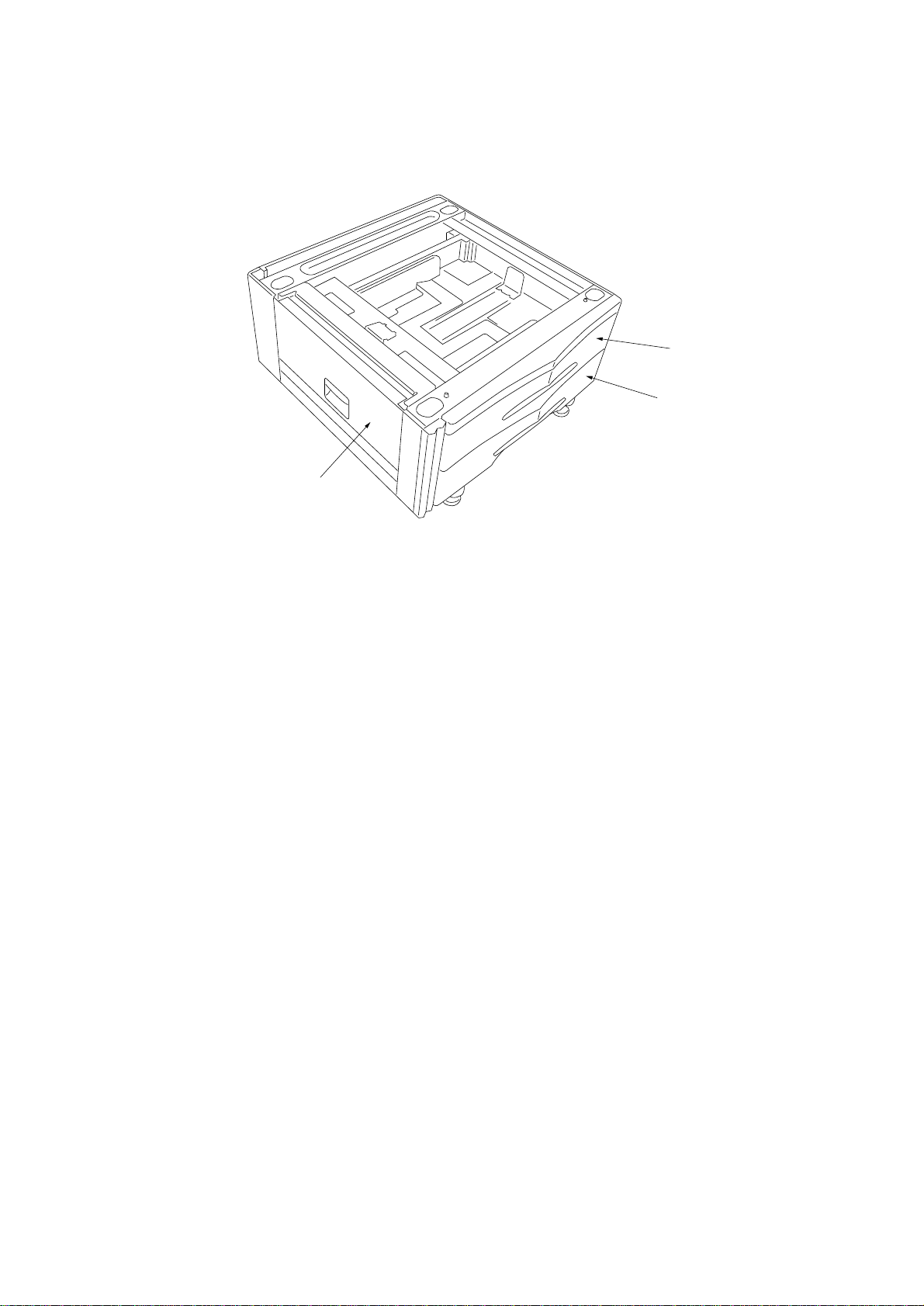
1-1-2 Parts names
1
2
3
Figure 1-1-1
1 Upper drawer
2 Lower drawer
3 Desk left cover
1-1-2
Page 6
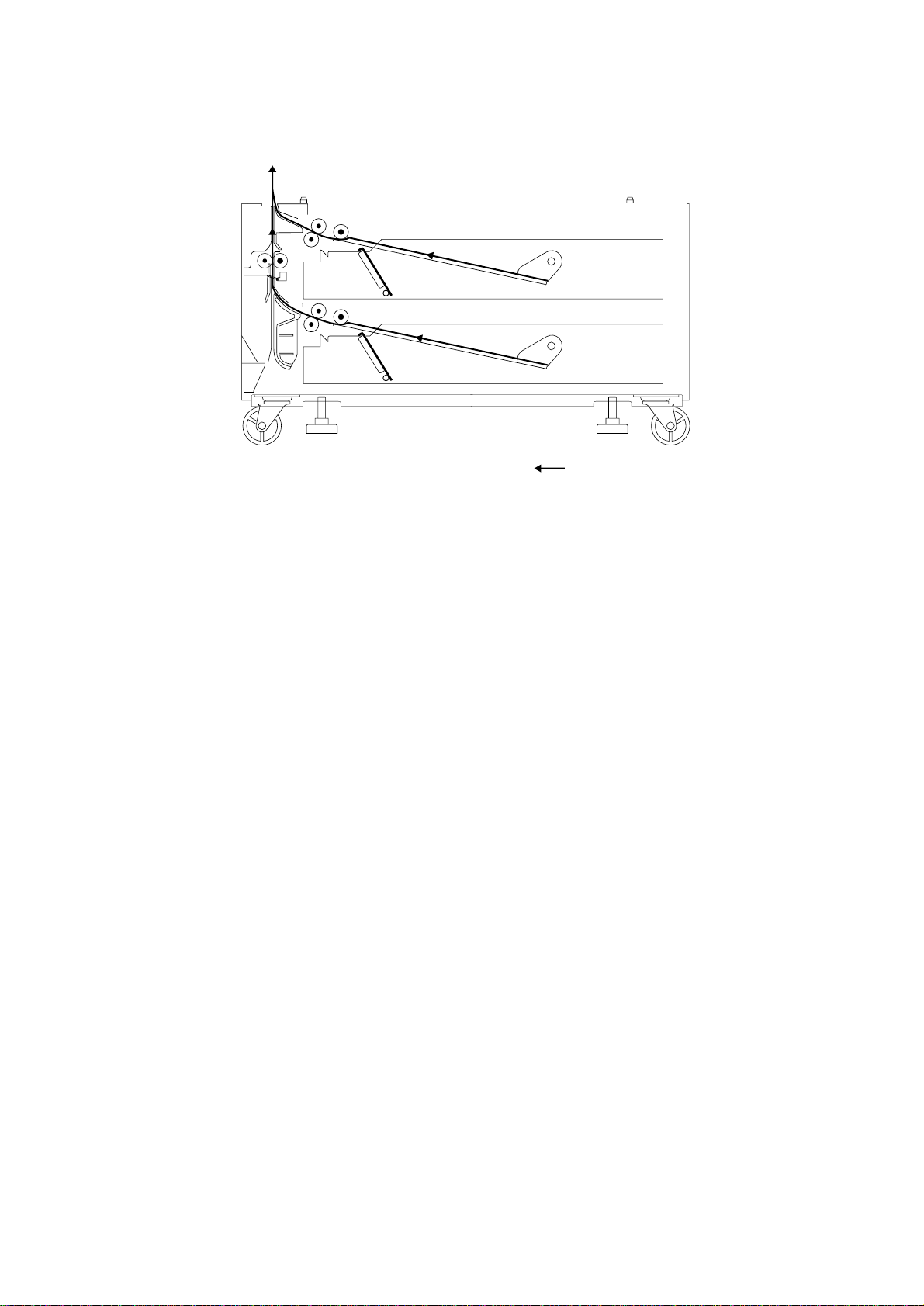
1-1-3 Machine cross section
3CC
Paper path
Figure 1-1-2 Machine cross section
1-1-3
Page 7

3CC
1-1-4 Drive system
84
9
7
6
3
2
1
5
Figure 1-1-3 Drive system
1 Desk drive motor gear
2 Idle gear 67/34
3 Gear 41
4 Desk upper paper feed clutch gear
5 Gear 41
As viewed from machine front
6 Desk lower paper feed clutch gear
7 Gear 20
8 Gear 26
9 Desk feed clutch gear
1-1-4
Page 8

1-2-1 Unpacking
3CC
#
0
8
9
234
56
%
@
0
^
8
!
1
0
Figure 1-2-1
1 Paper feed desk
2 Retainer
3 Cross-head chromate binding screws,
CVM4 × 06
4 Pins
5 Stays
6 Chrome TP screws, M4 × 10
7 Outer case
8 Bottom pads
$
7
9 Upper pad
0 Stays
! Machine cover
@ Rear spacer
# Plastic bag
$ Bar code label
% Plastic bag
^ Installation guide
1-2-1
Page 9
3CC
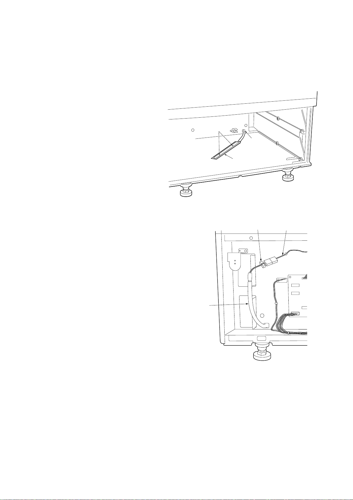
1-2-2 Installing the desk dehumidifier (service part)
Desk dehumidifier installation requires the following parts:
Desk dehumidifier (P/N 33960020): for 220 – 240 V specifications only
Desk dehumidifier (P/N 34860030): for 120 V specifications only
Two (2) M4 × 8 S tight screws (P/N B3324080)
Procedure
1. Remove the upper and lower drawers.
2. Remove the three screws holding the desk
rear cover and then the cover.
3. Pass the desk dehumidifier cable to the
machine rear through the cable hole in the
machine right.
4. Attach the desk dehumidifier using the two M4
× 8 S tight screws.
M4 × 8 S
tight screws
Cable hole
Desk dehumidifier
5. Insert the desk dehumidifier connector into the
connector of the main harness.
6. Tidy up the desk dehumidifier cable using the
wire saddle and route the cable while clipping
the wire saddles into the holes in the rear
frame.
7. Refit all removed parts.
Figure 1-2-2
Wire saddle Main harness
Desk dehumidifier
cable
Figure 1-2-3
1-2-2
Page 10
3CC
1-3-1 Paper misfeed detection
(1) Paper misfeed indication
When a paper jam occurs, the machine immediately stops operation. The operation unit of the copier shows a jam message
and the jam location.
To reset the paper misfeed detection, open and close the desk left cover to turn the desk safety switch off and on.
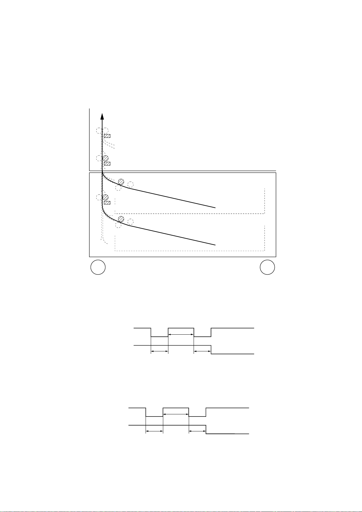
(2) Paper misfeed detection conditions
FSW2
FCL3
FSW3
DPFCL-U
DFCL
DFSW
DPFCL-L
Figure 1-3-1 Paper feed desk
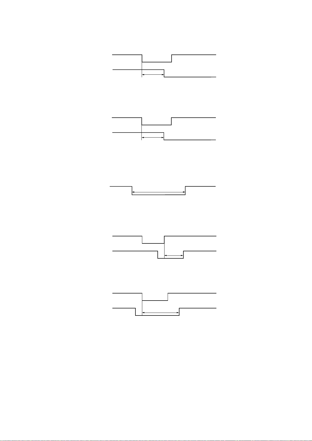
• No paper feed from desk upper drawer (jam code 12)
Feed switch 3 (FSW3) of the copier does not turn on within 880 ms of the desk upper paper feed clutch (DPFCL-U) turning
on; the clutch is then held off for 1 s and turned back on, but the switch again fails to turn on within 880 ms of the retry.
DPFCL-U
FSW3 (copier)
880 ms
1 s
880 ms
Off
On
Off
On
Timing chart 1-3-1
• No paper feed from desk lower drawer (jam code 13)
The desk feed switch (DFSW) does not turn on within 880 ms of the desk lower paper feed clutch (DPFCL-L) turning on; the
clutch is then held off for 1 s and turned back on, but the switch again fails to turn on within 880 ms of the retry.
DPFCL-L
DFSW
880 ms
1 s
880 ms
Off
On
Off
On
Timing chart 1-3-2
1-3-1
Page 11
3CC
• Jam in copier vertical paper conveying section (jam code 18)
Feed switch 2 (FSW2) of the copier does not turn on within 1203 ms of feed switch 3 (FSW3) of the copier turning on.
FSW3 (copier)
FSW2 (copier)
1203 ms
Off
On
Off
On
Timing chart 1-3-3
• Jam in paper feed desk vertical paper conveying section (jam code 19)
Feed switch 3 (FSW3) of the copier does not turn on within 888 ms of the desk feed switch (DFSW) turning on.
DFSW
FSW3 (copier)
888 ms
Off
On
Off
On
Timing chart 1-3-4
• Multiple sheets in paper feed section (jam code 21)
Feed switch 3 (FSW3) of the copier and the desk f eed switch (DFSW) do not turn off within the time required to convey the
length of the used paper size plus 635 ms of turning on.
FSW3 (copier)
DFSW
Paper size + 635 ms
Off
On
Timing chart 1-3-5
• Multiple sheets in vertical paper conveying section (jam code 22)
Feed switch 2 (FSW2) of the copier does not turn off within 1203 ms of feed switch 3 (FSW3) of the copier turning off.
FSW3 (copier)
FSW2 (copier)
1203 ms
Off
On
Off
On
Timing chart 1-3-6
Feed switch 2 (FSW2) of the copier does not turn off within 1203 ms of feed switch 3 (FSW3) of the copier turning on.
FSW3 (copier)
FSW2 (copier)
1203 ms
Off
On
Off
On
Timing chart 1-3-7
1-3-2
Page 12
(3) Paper misfeeds
3CC
Problem
(1)
A paper jam in the
paper feed section
is indicated during
copying (no paper
feed from desk
upper drawer).
Jam code 12
(2)
A paper jam in the
paper feed section
is indicated during
copying (no paper
feed from desk
lower drawer).
Jam code 13
Causes/check procedures
Paper in the desk upper
drawer is extremely curled.
Check if the paper feed
pulley, separation pulley or
forwarding pulley of the
desk upper drawer is
deformed.
Broken copier feed switch 3
actuator.
Defective copier feed switch
3.
Check if the desk upper
paper feed clutch
malfunctions.
Electrical problem with the
desk upper paper feed
clutch.
Paper in the desk lower
drawer is extremely curled.
Check if the paper feed
pulley, separation pulley or
forwarding pulley of the
desk lower drawer is
deformed.
Corrective measures
Change the paper.
Check visually and replace any deformed pulleys.
Check visually and replace feed switch 3 if the actuator is
broken.
Run maintenance item U031 and turn feed switch 3 on and off
manually. Replace feed switch 3 if indication of the corresponding switch on the operation panel is not displayed in reverse.
Run maintenance item U247 and select the desk upper paper
feed clutch on the operation panel to be turned on and off.
Check the status and remedy if necessary.
Check (see page 1-3-7).
Change the paper.
Check visually and replace any deformed pulleys.
(3)
A paper jam in the
paper feed section
is indicated during
copying (jam in
copier vertical paper
conveying section).
Jam code 18
Broken desk feed switch
actuator.
Defective desk feed switch.
Check if the desk lower
paper feed clutch
malfunctions.
Electrical problem with the
desk lower paper feed
clutch.
Broken copier feed switch 2
actuator.
Defective copier feed switch
2.
Check visually and replace the desk feed switch if the actuator
is broken.
With 5 V DC present at CN2-8 on the desk main PCB, check if
CN2-7 on the desk main PCB goes low when the desk feed
switch is turned on. If not, replace the desk feed switch.
Run maintenance item U247 and select the desk lower paper
feed clutch on the operation panel to be turned on and off.
Check the status and remedy if necessary.
Check (see page 1-3-7).
Check visually and replace feed switch 2 if the actuator is
broken.
Run maintenance item U031 and turn feed switch 2 on and off
manually. Replace feed switch 2 if indication of the corresponding switch on the operation panel is not displayed in reverse.
1-3-3
Page 13

3CC
Problem
(4)
A paper jam in the
paper feed section
is indicated during
copying (jam in
paper desk vertical
paper conveying
section).
Jam code 19
(5)
A paper jam in the
paper feed section
is indicated during
copying (multiple
sheets in paper feed
section).
Jam code 21
Causes/check procedures
Broken copier feed switch 3
actuator.
Defective copier feed switch
3.
Check if the desk lower
paper feed clutch
malfunctions.
Electrical problem with the
desk lower paper feed
clutch.
Check if the desk feed
clutch malfunctions.
Electrical problem with the
desk feed clutch.
Check if the desk feed
rollers or pulleys are soiled
with paper powder.
Check if the desk feed
rollers or pulleys are soiled
with paper powder.
Corrective measures
Check visually and replace feed switch 3 if the actuator is
broken.
Run maintenance item U031 and turn feed switch 3 on and off
manually. Replace feed switch 3 if indication of the corresponding switch on the operation panel is not displayed in reverse.
Run maintenance item U247 and select the desk lower paper
feed clutch on the operation panel to be turned on and off.
Check the status and remedy if necessary.
Check (see page 1-3-7).
Run maintenance item U247 and select the desk feed clutch
on the operation panel to be turned on and off. Check the
status and remedy if necessary.
Check (see page 1-3-7).
Check and clean with isopropyl alcohol if soiled.
Check and clean with isopropyl alcohol if soiled.
(6)
A paper jam in the
paper feed section
is indicated during
copying (multiple
sheets in copier
vertical conveying
section).
Jam code 22
Check if the copier feed
rollers or pulleys are soiled
with paper powder.
Check and clean with isopropyl alcohol if soiled.
1-3-4
Page 14

3CC
1-3-2 Self-diagnosis
(1) Self-diagnostic function
When a problem is detected in the paper feed desk, copying is disabled and the problem displayed on the operation unit of
the copier as a code consisting of “C” followed by a number between 0420 and 2600, indicating the nature of the problem.
After removing the problem, the self-diagnostic function can be reset by turning the desk safety switch off and back on.
(2) Self diagnostic codes
Code
C0420
C1030
Contents
Communication problem
An error code from the paper feed desk
is detected eight times in succession.
No communication: there is no reply
after 3 retries.
Abnormal communication: a
communication error (parity or
checksum error) is detected five times
in succession.
Desk upper lift motor problem
When the upper drawer of the paper
feed desk is inserted, the desk upper lift
limit switch does not turn on within 6 s
of the desk upper lift motor turning on
and the desk upper lift limit switch does
not turn on by turning off the desk
upper lift motor for 200 ms and retrying
twice.
During copying, the desk upper lift limit
switch does not turn on within 200 ms
of the desk upper lift motor turning on.
Causes
Poor contact of
the connector
terminals.
Defective copier
main PCB.
Defective desk
main PCB.
Broken gears or
couplings of the
desk upper lift
motor.
Defective desk
upper lift motor.
Poor contact of
the desk upper lift
motor connector
terminals.
Defective desk
upper lift limit
switch.
Remarks
Check procedures/corrective measures
Check the connection of connectors CN3
on the copier main PCB and CN5 on the
desk main PCB, and the continuity across
the connector terminals. Remedy or
replace if necessary.
Replace the copier main PCB and check
for correct operation.
Replace the desk main PCB and check for
correct operation.
Replace the desk upper lift motor.
Check for continuity across the coil. If
none, replace the desk upper lift motor.
Reinsert the connector. Also check for
continuity within the connector cable. If
none, repair or replace the cable.
Check if CN1-5 on the desk main PCB
goes low when the desk upper lift limit
switch is turned off. If not, replace the desk
upper lift limit switch.
Poor contact of
the desk upper lift
limit switch
connector
terminals.
Reinsert the connector. Also check for
continuity within the connector cable. If
none, repair or replace the cable.
1-3-5
Page 15

3CC
Code
C1040
C1170
Contents
Desk lower lift motor problem
When the lower drawer of the paper
feed desk is inserted, the desk lower lift
limit switch does not turn on within 6 s
of the desk lower lift motor turning on
and the desk lower lift limit switch does
not turn on by turning off the desk lower
lift motor for 200 ms and retrying twice.
During copying, the desk lower lift limit
switch does not turn on within 200 ms
of the desk lower lift motor turning on.
Paper feed desk incorrect type
problem
Causes
Broken gears of
couplings of the
desk lower lift
motor.
Defective desk
lower lift motor.
Poor contact of
the desk lower lift
motor connector
terminals.
Defective desk
lower lift limit
switch.
Poor contact of
the desk lower lift
limit switch
connector
terminals.
Desk for the
printer is installed.
Remarks
Check procedures/corrective measures
Replace the desk lower lift motor.
Check for continuity across the coil. If
none, replace the desk lower lift motor.
Reinsert the connector. Also check for
continuity within the connector cable. If
none, repair or replace the cable.
Check if CN1-7 on the desk main PCB
goes low when the desk lower lift limit
switch is turned off. If not, replace the desk
lower lift limit switch.
Reinsert the connector. Also check for
continuity within the connector cable. If
none, repair or replace the cable.
Replace the desk fot the copier.
C2600
Desk drive motor problem
No pulse is input within 500 ms of the
start-up.
No pulse is input within 100 ms of the
previous pulse input.
Defective desk
drive motor PCB.
Desk drive motor
does not rotate
correctly (the
motor is overloaded).
Poor contact in
the desk drive
motor connector
terminals.
Replace the desk drive motor PCB and
check for correct operation.
Check the gears and remedy if necessary.
Reinsert the connector. Also check for continuity within the connector cable. If none,
remedy or replace the cable.
1-3-6
Page 16

1-3-3 Electrical problems
3CC
Problem
(1)
The paper feed
desk does not
operate when the
copier print key is
pressed.
(2)
The desk drive
motor does not
operate.
(3)
The desk upper
paper feed clutch
does not operate.
Causes
Poor contact of the signal
cable connector terminals
between the paper feed
desk and the copier.
Defective desk safety
switch.
Poor contact of the desk
drive motor connector
terminals.
Broken desk drive motor
gear.
Defective desk drive motor.
Defective desk main PCB.
Broken desk upper paper
feed clutch coil.
Poor contact of the desk
upper paper feed clutch
connector terminals.
Check procedures/corrective measures
Reinsert the connector. Also check for continuity within the
connector cable. If none, repair or replace the cable.
Check for continuity across the contacts. If none, replace the
desk safety switch.
Reinsert the connector. Also check for continuity within the
connector cable. If none, repair or replace the cable.
Check visually and replace the desk drive motor if necessary.
Check if the desk drive motor operates when CN4-6 on the
desk main PCB goes low. If not, replace the desk drive motor.
Check if CN4-6 on the desk main PCB goes low when the desk
drive motor is operated in maintenance item U247. If not,
replace the desk main PCB.
Check for continuity across the coil. If none, replace the desk
upper paper feed clutch.
Reinsert the connector. Also check for continuity within the
connector cable. If none, repair or replace the cable.
(4)
The desk lower
paper feed clutch
does not operate.
(5)
The desk feed
clutch does not
operate.
Defective desk main PCB.
Broken desk lower paper
feed clutch coil.
Poor contact of the desk
lower paper feed clutch
connector terminals.
Defective desk main PCB.
Broken desk feed clutch
coil.
Poor contact of the desk
feed clutch connector
terminals.
Defective desk main PCB.
Check if CN1-14 on the desk main PCB goes low when the
desk upper paper feed clutch is operated in maintenance item
U247. If not, replace the desk main PCB.
Check for continuity across the coil. If none, replace the desk
lower paper feed clutch.
Reinsert the connector. Also check for continuity within the
connector cable. If none, repair or replace the cable.
Check if CN1-13 on the desk main PCB goes low when the
desk lower paper feed clutch is operated in maintenance item
U247. If not, replace the desk main PCB.
Check for continuity across the coil. If none, replace the desk
feed clutch.
Reinsert the connector. Also check for continuity within the
connector cable. If none, repair or replace the cable.
Check if CN2-1 on the desk main PCB goes low when the desk
feed clutch is operated in maintenance item U247. If not,
replace the desk main PCB.
1-3-7
Page 17

3CC
Problem
(6)
The desk upper lift
motor does not
operate.
(7)
The desk lower lift
motor does not
operate.
(8)
The size of paper in
the upper drawer is
not displayed
correctly.
Causes
Broken desk upper lift motor
coil.
Poor contact of the desk
upper lift motor connector
terminals.
Defective desk main PCB.
Broken desk lower lift motor
coil.
Poor contact of the desk
lower lift motor connector
terminals.
Defective desk main PCB.
Poor contact of the desk
upper paper length switch
connector terminals.
Poor contact of the desk
upper paper width switch
connector terminals.
Check procedures/corrective measures
Check for continuity across the coil. If none, replace the desk
upper lift motor.
Reinsert the connector. Also check for continuity within the
connector cable. If none, repair or replace the cable.
Check if 24 V DC is output across CN2-5 (–) and CN2-6 (+) on
the desk main PCB right after the desk upper drawer is
installed. If not, replace the desk main PCB.
Check for continuity across the coil. If none, replace the desk
lower lift motor.
Reinsert the connector. Also check for continuity within the
connector cable. If none, repair or replace the cable.
Check if 24 V DC is output across CN2-3 (–) and CN2-4 (+) on
the desk main PCB right after the desk lower drawer is
installed. If not, replace the desk main PCB.
Reinsert the connector. Also check for continuity within the
connector cable. If none, repair or replace the cable.
Reinsert the connector. Also check for continuity within the
connector cable. If none, repair or replace the cable.
(9)
The size of paper in
the lower drawer is
not displayed
correctly.
Defective desk upper paper
length switch.
Defective desk upper paper
width switch.
Poor contact of the desk
lower paper length switch
connector terminals.
Poor contact of the desk
lower paper width switch
connector terminals.
Defective desk lower paper
length switch.
Defective desk lower paper
width switch.
Check if CN3-7 on the desk main PCB goes low when the desk
upper paper length switch is turned on. If not, replace the desk
upper paper length switch.
Check for continuity between CN3-9 and CN3-1, CN3-2, and
CN3-3 on the desk main PCB. If the continuity is unaffected by
movement of the width guides in the upper drawer (i.e. either
remains present or remains absent), then replace the desk
upper paper width switch.
Reinsert the connector. Also check for continuity within the
connector cable. If none, repair or replace the cable.
Reinsert the connector. Also check for continuity within the
connector cable. If none, repair or replace the cable.
Check if CN3-8 on the desk main PCB goes low when the desk
lower paper length switch is turned on. If not, replace the desk
lower paper length switch.
Check for continuity between CN3-10 and CN3-4, CN3-5, and
CN3-6 on the desk main PCB. If the continuity is unaffected by
movement of the width guides in the lower drawer (i.e. either
remains present or remains absent), then replace the desk
lower paper width switch.
1-3-8
Page 18

3CC
Problem
(10)
The message
requesting covers to
be closed is
displayed when the
desk left cover is
closed.
(11)
Others.
Causes
Poor contact of the desk
safety switch connector
terminals.
Defective desk safety
switch.
Wiring is broken, shorted or
makes poor contact.
Noise.
Check procedures/corrective measures
Reinsert the connector. Also check for continuity within the
connector cable. If none, repair or replace the cable.
Check for continuity across the contacts. If there is no
continuity when the desk safety switch is on, replace it.
Check for continuity. If none, repair.
Locate the source of noise and remove.
1-3-9
Page 19

3CC
1-3-4 Mechanical problems
Problem
(1)
No paper feed.
(2)
Skewed paper feed.
(3)
Multiple sheets of paper
are fed at one time.
(4)
Paper jams.
Causes/check procedures
Check if the surfaces of the following rollers
and pulleys are soiled with paper powder:
forwarding pulley, paper feed pulley,
separation pulley, desk feed roller and desk
feed pulley.
Check if the paper feed pulley or separation
pulley is deformed.
Check if the forwarding pulley is deformed.
Electrical problem with the following
electromagnetic clutches: desk upper/lower
paper feed clutches and desk feed clutch.
Width guide in the drawer installed
incorrectly.
Deformed width guide in the drawer.
Check if the separation pulley is deformed.
Check if the paper is curled.
Check if the paper is excessively curled.
Deformed guides along the paper conveying
path.
Corrective measures
Clean with isopropyl alcohol.
Replace (see page 1-4-2).
Replace (see page 1-4-2).
See pages 1-3-7.
Check the width guide visually and remedy
or replace if necessary.
Check the width guide visually and remedy
or replace if it is deformed.
Replace the separation pulley if it is worn
(see page 1-4-2).
Change the paper.
Change the paper.
Check visually and remedy or replace any
deformed guides.
(5)
Abnormal noise is
heard.
Check if the pulleys, rollers and gears
operate smoothly.
Check if the desk upper and lower paper
feed clutches and the desk feed clutch are
installed correctly.
Grease the bearings and gears.
Remedy.
1-3-10
Page 20

1-4-1 Precautions for assembly and disassembly
(1) Precautions
• Be sure to turn the main switch off and disconnect the power plug before starting disassembly.
• When handling PCBs, do not touch connectors with bare hands or damage the board.
• Do not touch PCBs containing ICs with bare hands or any object prone to static charge.
• Use the following testers when measuring voltages:
Hioki 3200
Sanwa MD-180C
Sanwa YX-360TR
Beckman TECH300
Beckman DM45
Beckman 330 (capable of measuring RMS values)
Beckman 3030 (capable of measuring RMS values)
Beckman DM850 (capable of measuring RMS values)
Fluke 8060A (capable of measuring RMS values)
Arlec DMM1050
Arlec YF1030C
3CC
1-4-1
Page 21

3CC
1-4-2 Paper feed section
(1) Detaching and refitting the forwarding, paper feed and separation pulleys
Replace the forwarding, paper feed and separation pulleys as follows.
Procedure
• Removing the primary paper feed units
1. Remove the upper and lower drawers.
2. Remove the two screws holding the lower
front cover and then the cover.
3. Remove the one screw from each of the
primary paper feed units and then the units.
Screws
Primary paper
feed units
• Removing the forwarding pulley
4. Remove the stopper.
5. Raise the forwarding pulley retainer in the
direction of the arrow, and remove from the
primary paper feed unit.
6. Remove the stop ring, pull the forwarding
pulley shaft in the direction of the arrow, and
remove the forwarding pulley.
Figure 1-4-1 Detaching the primary paper feed units
Forwarding pulley retainer
Stopper
Figure 1-4-2 Detaching the forwarding pulley retainer
Forwarding pulley
Stop ring
Forwarding pulley shaft
1-4-2
Figure 1-4-3 Detaching the forwarding pulley
Page 22

• Removing the paper feed pulley
7. Remove the two stop rings.
8. Pull the paper feed shaft toward the rear of
the primary paper feed unit (in the direction of
the arrow) and remove the paper feed pulley
and gear.
• Removing the separation pulley
9. Remove the stop ring from the rear of the
primary paper feed unit.
10. Pull the separation shaft toward the rear of
the machine (in the direction of the arrow)
and remove the separation pulley.
11. Replace the forwarding, paper feed and
separation pulleys.
12. Refit all removed parts.
Stop rings
Paper feed shaft Gear Paper feed pulley
Figure 1-4-4 Detaching the paper feed pulley
Stop ring
Separation shaft
Separation pulley
3CC
Cautions:
• When fitting the forwarding pulley, orient it
correctly as shown in Figure 1-4-6.
• When fitting the paper feed pulley and gear , keep
the blue end of the paper feed pulley and the
black end of the gear toward the machine rear.
Figure 1-4-5 Detaching the separation pulley
Machine front Machine rear
Forwarding pulley
Figure 1-4-6
1-4-3
Page 23

3CC
(2) Replacing the desk upper or lower paper width switches
Replace the desk upper or lower paper width switches as follows.
Caution:
After replacing a desk paper width switch, be sure to perform (4) Adjusting the position of the rack adjuster.
Procedure
1. Remove the drawer.
Screws
2. Remove the two screws and 8-pin socket
from the rear of the drawer.
3. Detach the 8-pin desk paper width switch
connector from the 8-pin socket.
4. Remove the three screws holding the rack
adjuster.
5. While raising the drawer lift in the direction of
8-pin socket
the arrow, remove the rack adjuster.
Screws
8-pin connector
Figure 1-4-7 Detaching the rack adjuster
Rack adjuster
Drawer lift
6. Remove the two screws from the back of the
rack adjuster and then the desk paper width
switch.
7. Apply the specified grease to the printed
surface of the new desk paper width switch
(shaded area in the diagram) and fit the
switch to the rack adjuster.
8. Refit all removed parts.
Screws
Desk paper width switch
Figure 1-4-8 Detaching the desk paper width switch
Apply the specified grease.
1-4-4
Figure 1-4-9 Desk paper width switch
Page 24

(3) Replacing the desk feed, upper and lower paper feed clutches
Replace the desk feed, upper and lower paper feed clutches as follows.
Procedure
1. Remove the three screws holding the desk
Clamp
rear cover and then the cover.
2. Remove the cable from the retainer clamp.
3. Remove the three screws holding the retainer
and then the retainer.
4. Remove the two screws holding the rear
cover left retainer and then the retainer.
Screws
Retainer
Figure 1-4-10
3CC
Screws
Rear cover
left retainer
5. Remove the upper and lower stop rings and
bearings from the desk upper and lower
paper feed clutches.
6. Remove the stop ring from the desk feed
clutch.
7. Remove the three screws holding the desk
drive motor retainer and then the retainer.
Desk upper paper feed clutch
Stop ring and bearing
Desk feed clutch
Stop ring
Desk lower paper
feed clutch
Stop ring and bearing
Figure 1-4-11
Desk drive motor retainer
Screws
Figure 1-4-12 Detaching the desk drive motor retainer
1-4-5
Page 25

3CC
8. Remove the connectors of the desk feed,
upper and lower paper feed clutches and
then the clutches.
9. Replace the clutches.
10. Refit all removed parts.
Caution:
When fitting the clutches, be sure to refit the whirl-stops.
Desk upper paper feed clutch
Connector
Desk feed clutch
Connector
Desk lower paper
feed clutch
Connector
Figure 1-4-13 Detaching the desk feed, upper and lower
paper feed clutches
1-4-6
Page 26

3CC
(4) Adjusting the position of the rack adjuster
Perform the following adjustment if there is a regular error between the center lines of the copy image and the original on the
paper fed from the drawer.
Procedure
Start
Enter maintenance mode.
Run maintenance item U993.
Select “VTC PG1” and output
a test pattern.
Is the image correct?
Yes
Exit maintenance mode.
End
No
Correct image Output
Loosen the three screws holding
the rack adjuster and change the
position of the adjuster so that
the centers of the original and
the copy image are aligned.
• For output example 1, move
toward the machine front ( ).
• For output example 2, move
toward the machine rear ( ).
Screws
example 1
Figure 1-4-14
Output
example 2
Rack adjuster
Figure 1-4-15 Adjusting the position of the rack adjuster
1-4-7
Page 27

3CC
(5) Adjusting the amount of slack
Perform the f ollowing adjustment if the leading edge of the cop y image is missing or v aries randomly, or if the copy paper is
Z-folded.
Procedure
Start
Enter maintenance mode.
Enter “051” using the numeric keys.
Press the start key.
Select “FEED DATA.”
Select the drawer to be adjusted.
Press the interrupt key.
Press the start key
to make a test copy.
Is the leading edge
of the image missing or varying randomly
(copy example 1)?
No
Is the copy paper
Z-folded (copy example 2)?
Yes
Yes
Original Copy
Press the start key.
The new setting is stored.
Increase the value using
the cursor upper key.
Decrease the value using
the cursor lower key.
example 1
Figure 1-4-16
Copy
example 2
1-4-8
No
Press the stop/clear key.
Exit maintenance mode.
End
Setting range: 0 – 255
Changing the value by 1 changes
the amount of slack by 0.67 mm
Reference: 0
The greater the value, the larger
the amount of slack;
The smaller the value, the smaller
the amount of slack.
Page 28

3CC
2-1-1 Mechanical construction
The paper feed desk feeds paper from either of its two drawers to the copier main body. When paper is fed from the lower
drawer of the paper feed desk, the desk feed clutch (DFCL) is operated to rotate the desk feed roller and pulley to carry the
paper into the copier main body.
82@
$
4
5
&
!
9
2
#
3
^
3
0
Figure 2-1-1 Paper feed desk
1 Forwarding pulley
2 Paper feed pulley
3 Separation pulley
4 Desk feed roller
5 Desk feed pulley
6 Drawer lift
7 Lift operating plate
8 Desk upper feed guide
9 Desk middle feed guide
0 Desk lower feed guide
! Desk feed guide
@ Desk upper paper feed clutch (DPFCL-U)
(
%
1
*
1
6
7
¤
6
7
‹
# Desk lower paper feed clutch (DPFCL-L)
$ Desk feed clutch (DFCL)
% Desk upper paper switch (DPSW-U)
^ Desk lower paper switch (DPSW-L)
& Desk feed switch (DFSW)
* Desk upper lift limit switch (DLICSW-U)
( Desk lower lift limit switch (DLICSW-L)
) Desk upper paper length switch (DPLSW-U)
⁄ Desk lower paper length switch (DPLSW-L)
¤ Desk upper paper width switch (DPWSW-U)
‹ Desk lower paper width switch (DPWSW-L)
)
⁄
DPSW-U
DPFCL-U
DFCL
DFSW
Figure 2-1-2 Paper feed desk block diagram
DPFCL-L
DPSW-L DLICSW-L
DLICSW-U
DMPCB
CN1-5
CN1-6
CN1-14
CN2-1
CN1-7
CN1-8
CN1-13
CN2-7
2-1-1
Page 29

3CC
• Paper feed from the desk upper drawer
Start key
DDM
FCL3 (copier)
100 ms
a
d
17 ms
c
b
DPFCL-U
RSW (copier)
FSW3 (copier)
DM (copier)
Timing chart 2-1-1 Paper feed from the desk upper drawer
a 100 ms after the start key is pressed, the desk drive motor (DDM) turns on at the same time as the drive motor (DM) turns
on, starting the drive for the paper feed desk. The desk upper paper feed clutch (DPFCL-U) turns on to start rotating the
forwarding pulley and paper feed pulley to start paper feed from the upper drawer.
b 1379 ms after the leading edge of the paper turns the feed switch 3 (FSW3) on, the desk upper paper feed clutch (DPFCL-
U) turns off.
c 17 ms after the leading edge of the paper turns the registration switch (RSW) on, feed clutch 3 (FCL3) turns off.
d The desk drive motor (DDM) turns off at the same time as the drive motor (DM) turns off to stop the drive for the paper feed
desk.
1379 ms
Automatic copy density control;
A3/11" × 17" paper; magnification of 100%
2-1-2
Page 30

• Paper feed from the desk lower drawer
Start key
100 ms
DDM
FCL3 (copier)
DFCL
DPFCL-L
FSW3 (copier)
DFSW
DM (copier)
a
b
c
123 ms
344 ms
123 ms
d
A4/11" × 8
f
e
Manual copy density control;
1
/2" paper; magnification of 100%
3CC
Timing chart 2-1-2 Paper feed from the desk lower drawer
a 100 ms after the start key is pressed, the desk drive motor (DDM) turns on at the same time as the drive motor (DM) turns
on, starting the drive for the paper feed desk. The desk lower paper feed clutch (DPFCL-L) turns on to start rotating the
forwarding pulley and paper feed pulley to start paper feed from the lower drawer.
b At the same time as the leading edge of the paper turns the desk feed switch (DFSW) on, the desk feed clutch (DFCL) turns
on to rotate the desk feed roller to convey the paper to the copier.
c 344 ms after the desk feed switch (DFSW) turns on, the desk lower paper feed clutch (DPFCL-L) turns off.
d 123 ms after the trailing edge of the paper turns the desk feed switch (DFSW) off, the desk feed clutch (DFCL) turns off.
e 123 ms after the trailing edge of the paper turns feed switch 3 (FSW3) off, feed clutch 3 (FCL3) turns off.
f The desk drive motor (DDM) turns off at the same time as the drive motor (DM) turns off to stop the drive for the paper feed
desk.
2-1-3
Page 31

2-2-1 Electrical parts layout
35
15
3CC
16
12
13
9
46
14
10
18
Machine front Machine inside Machine rear
1
7
8
17
2
11
Figure 2-2-1 Layout of electrical parts
1. Desk main PCB (DMPCB) ........................... Controls electrical parts.
2. Desk safety switch (DSSW) ......................... Breaks the safety circuit when the desk left cover is opened, and resets
paper jam detection.
3. Desk upper paper switch (DPSW-U) ........... Detects the presence of paper in the desk upper drawer.
4. Desk lower paper switch (DPSW-L)............. Detects the presence of paper in the desk lower drawer.
5. Desk upper lift limit switch (DLICSW-U) ...... Detects the desk upper drawer lift reaching the upper limit.
6. Desk lower lift limit switch (DLICSW-L)........ Detects the desk lower drawer lift reaching the upper limit.
7. Desk upper paper length switch (DPLSW-U)Detects the length of paper in the desk upper drawer.
8. Desk lower paper length switch (DPLSW-L) Detects the length of paper in the desk lower drawer.
9. Desk upper paper width switch (DPWSW-U)Detects the width of paper in the desk upper drawer.
10. Desk lower paper width switch (DPWSW-L) Detects the width of paper in the desk lower drawer.
11. Desk feed switch (DFSW) ............................ Controls the desk lower paper feed clutch.
12. Desk drive motor (DDM) .............................. Drives the paper feed desk.
13. Desk upper lift motor (DCLM-U) .................. Drives the desk upper drawer lift.
14. Desk lower lift motor (DCLM-L) ................... Drives the desk lower drawer lift.
15. Desk upper paper feed clutch (DPFCL-U) ... Primary paper feed from the desk upper drawer.
16. Desk lower paper feed clutch (DPFCL-L) .... Primary paper feed from the desk lower drawer.
17. Desk feed clutch (DFCL) ............................. Conveys paper to the copier.
18.Desk dehumidifier* (DDH)............................. Dehumidifies paper.
* Service part.
2-2-1
Page 32

2-3-1 Desk main PCB
3CC
DMPCB
DDM
DCLM-U
DCLM-L
DPFCL-U
DPFCL-L
DFCL
DPSW-U
DPSW-L
DLICSW-U
DLICSW-L
DPLSW-U
DPLSW-L
DPWSW-U
DPWSW-L
Motor
driver
(IC8)
CPU
(IC5)
DESK RXD
DESK TXD
FSW SIG
DSSW
DFSW
Copier
main PCB
(MPCB)
Figure 2-3-1 Desk main PCB block diagram
The desk main PCB (DMPCB) is controlled from the copier main PCB (MPCB) which controls the inputs from and outputs
to the motors, clutches and switches on the paper feed desk through the CPU IC5 serially via two-way serial/parallel 8-bit
data conversion.
2-3-1
Page 33

J10
1
J32
J26
J47
J75
J9
J77
J76
J78
J106
J28
J43
J45
J48
J49
J46
L25
J83
J87
J88
J84
J89
J90
J85
J86
CN2
L9
J30
J29
J51
J108
J31
J50
J110
L23
C20
J52
J53
17
18
+
J54
J109
CN4
CN6
L13
11
1
12
2
J111
3
1
7
1
CN3
L14
J55
J91
J92
Figure 2-3-2
J68
J69
C40
J98
J17
J8
L7
J6
C4
J7
J18
J21
J19
IC5
J72
J71
J73
IC7
11
J102
J100 J101J99
12
1
J22
IC8
X1
IC3
22
8
J103
IC1
J24
J40
J104 J74
+
J23
C16
J42
J80
J81
J82
J41
J44
C42
9
L24
8
J25
J27
+
J79
J107
1
J105
CN5
110
J1
J4
D1
IC2
1
IC4
J33
J61
J56
J93
CN1
1
2
J59
J94
J35
J95
8
J58
J57
J2
J13
J12J11
15
16
J36
J60
J3
J34
J62
J96
J38
IC6
J97
J5
J15
J37
J65
J66
L22
J63
J67
J14
J70
J20
J64
L5D2
+
J16
J39
8
+
3CC
2-3-2
Page 34

Terminals (CN) V olta ge Remarks
1-1 1-9 5 V DC 5 V DC supply for DLICSW-U, output
1-2 1-10 5 V DC 5 V DC supply for DPSW-U, output
1-3 1-11 5 V DC 5 V DC supply for DLICSW-L, output
1-4 1-12 5 V DC 5 V DC supply for DPSW-L, output
1-5 1-9 5/0 V DC DLICSW-U on/off, input
1-6 1-10 0/5 V DC DPSW-U on/off, input
1-7 1-11 5/0 V DC DLICSW-L on/off, input
1-8 1-12 0/5 V DC DPSW-L on/off, input
1-13 5-8 0/24 V DC DPFCL-L on/off, input
1-14 5-8 24 V DC 24 V DC supply for DPFCL-L, output
1-15 5-8 0/24 V DC DPFCL-U on/off, input
1-16 5-8 24 V DC 24 V DC supply for DPFCL-U, output
2-1 5-8 0/24 V DC DFCL on/off, input
2-2 5-8 24 V DC 24 V DC supply for DFCL, output
2-3 5-8 0/24 V DC DCLM-L on/off, input
2-4 5-8 24 V DC 24 V DC supply for DCLM-L, output
2-5 5-8 0/24 V DC DCLM-U on/off, input
2-6 5-8 24 V DC 24 V DC supply for DCLM-U, output
2-7 2-9 0/5 V DC DFSW on/off, output
2-8 2-9 5 V DC 5 V DC supply for DFSW, output
2-15 2-13 0/5 V DC Paper level detection switch on/off, input
2-16 2-14 0/5 V DC Paper level detection switch on/off, input
2-17 2-13 0/5 V DC Paper level detection switch on/off, input
2-18 2-14 0/5 V DC Paper level detection switch on/off, input
3-1 3-9 0/5 V DC DPWSW-U (DIG0) on/off, input
3-2 3-9 0/5 V DC DPWSW-U (DIG1) on/off, input
3-3 3-9 0/5 V DC DPWSW-U (DIG2) on/off, input
3-4 3-10 0/5 V DC DPWSW-L (DIG0) on/off, input
3-5 3-10 0/5 V DC DPWSW-L (DIG1) on/off, input
3-6 3-10 0/5 V DC DPWSW-L (DIG2) on/off, input
3-7 3-11 0/5 V DC DPLSW-U on/off, input
3-8 3-12 0/5 V DC DPLSW-L on/off, input
4-1 4-2 24 V DC 24 V DC supply for DDM, output
4-4 4-3 5 V DC 5 V DC supply for DDM, output
4-5 4-2 0/5 V DC (pulse) Clock signal to DDM, output
4-6 4-2 0/5 V DC DDM on/off, output
4-7 4-2 0/5 V DC LOCK signal to DDM, input
5-1 5-2 0/5 V DC FSW3 on/off from the copier, input
5-3 5-2 0/5 V DC (pulse) Serial communication signal to the copier, output
5-5 5-4 0/5 V DC (pulse) Serial communication signal to the copier, input
5-6 5-7 5 V DC 5 V DC supply, input
5-10 5-8 24 V DC 24 V DC supply, input
6-1 5-8 24/0 V DC DSSW on/off, input
6-3 5-8 24 V DC 24 V DC supply for DSSW, output
3CC
2-3-3
Page 35

Start key
DM CN11-A3
DDM CN4-6
RCL CN10-A5
FCL1 CN10-A7
FCL2 CN10-A9
FCL3 CN10-A11
DPFCL-UCN1-14
MC REM CN9-14
FSM CN2-7, 8, 9, 10
CL CN13-4
RSW CN8-25
ESW CN2-15
FSW1 CN15-5
FSW2 CN15-8
FSW3 CN15-11
TC REMCN9-9
DB REMCN9-11
17 ms
78 ms
124 ms
124 ms
48 ms
Min 78 ms
100 ms
30 ms
30 ms
100 ms
190 ms
190 ms
1055 ms
1379 ms
323 ms
323 ms
350 ms
500 ms
518 ms
300 ms
200 ms
Image ready
215 ms
17 ms
1379 ms
3CC
Timing chart No. 1 Continuous copying an A3/11" × 17" original onto two sheets of A3/11" × 17" copy paper from the paper feed
desk upper drawer, magnification ratio 100%, auto copy density control
2-4-1
Page 36

3CC
Start key
DM CN11-A3
DDM CN4-6
RCL CN10-A5
FCL1 CN10-A7
FCL2 CN10-A9
FCL3 CN10-A11
DFCL CN2-1
DPFCL-L CN1-13
MC REMCN9-14
FSM CN2-7, 8, 9, 10
CL CN13-4
RSW CN8-25
ESW CN2-15
FSW1 CN15-5
FSW2 CN15-8
FSW3 CN15-11
DFSW CN2-7
TC REM CN9-9
DB REM CN9-11
100 ms
123 ms
123 ms
17 ms
30 ms
48 ms
Min 78 ms
124 ms
100 ms
344 ms
323 ms
518 ms
500 ms
200 ms
300 ms
350 ms
190 ms
Image ready
215 ms
" copy paper from the paper feed desk lower drawer,
2
/
1
" original onto an A4/11" × 8
2
/
1
magnification ratio 100%, manual copy density control
Timing chart No. 2 Copying an A4/11" × 8
2-4-2
Page 37

Wiring diagram
A B C D E F G H IJ
1
2
C113
RD:C101-15
RD:C121-1
BE:C103-10
GN:C103-4
PE:C103-5
PK:C103-6
14325678
C311
RD:C311-3
RD:C311-4
BE:C312-1
YW:C312-2
LB:C312-3
PK:C312-4
76583412
BE:C311-8
YW:C311-5
LB:C311-6
PK:C311-7
LOWER DRAWER
C312
1
GND
2
DPWSW-U DIG0
3
DPWSW-U DIG1
4
DPWSW-U DIG2
5
DPWSW-U
C112
RD:C101-16
RD:C117-1
BE:C103-9
GN:C103-1
PE:C103-2
PK:C103-3
C116
OE:C101-4
LB:C101-8
BE:C101-12
OE:C101-3
YW:C101-7
BE:C101-11
14325678
14325678
C301
RD:C301-3
RD:C301-4
BE:C302-1
YW:C302-2
LB:C302-3
PK:C302-4
76583412
C211
GY:C213-1
GY:C213-2
GY:C213-3
GY:C212-1
GY:C212-2
GY:C212-3
78563412
BE:C301-8
YW:C301-5
LB:C301-6
PK:C301-7
GY:C211-4
GY:C211-3
GY:C211-6
GY:C211-5
GY:C211-8
GY:C211-7
UPPER DRAWER
C302
1
GND
2
DPWSW-L DIG0
3
DPWSW-L DIG1
4
DPWSW-L DIG2
5
LOWER DRAWER
PAPER FEED UNIT
C213
1
5 V
2
DPSW-L
3
GND
1
5 V
2
DLICSW-L
3
GND
C212
DPWSW-L
DPSW-L
DLICSW-L
C115
OE:C101-2
LB:C101-6
BE:C101-10
OE:C101-1
YW:C101-5
BE:C101-9
12345678
C201
GY:C203-1
GY:C203-2
GY:C203-3
GY:C202-1
GY:C202-2
GY:C202-3
78563412
GY:C201-4
GY:C201-3
GY:C201-6
GY:C201-5
GY:C201-8
GY:C201-7
UPPER DRAWER
PAPER FEED UNIT
C203
1
5 V
2
DPSW-U
3
GND
1
5 V
2
DLICSW-U
3
GND
C202
3CC
1
2
DPSW-U
DLICSW-U
3
DDM
4
RD:C104-1
BE:C104-2
DPLSW-U
DPLSW-L
BE:C104-3
OE:C104-4
YW:C104-5
YW:C104-6
GN:C104-7
DDH
RD:C102-4
5
GN:C102-3
LB:C102-15
BE:C102-13
PE:C102-17
6
C110
1
24 V
2
DCLM-U REM
3
DCLM-U SIG1
4
COM
5
DCLM-U SIG2
YW:C103-7
BE:C103-11
YW:C103-8
BE:C103-12
CN107
1
GND
2
DPLSW-U
CN106
1
GND
2
DPLSW-L
DCLM-U
C114
1
24 V
2
GND
3
GND
4
5 V
5
DDM CLOCK
6
DDM REM
7
DDM LOCK
RD:C102-6
GN:C102-5
LB:C102-16
BE:C102-14
PE:C102-18
YW:C101-13
RD:C113-5
C108
1
24 V
2
DCLM-L REM
3
DCLM-L SIG1
4
COM
5
DCLM-L SIG2
C124C121
1
DPFCL-L REM
3
2
2
24 V
3
1
DPFCL-L
DCLM-L
C119 C401 C402
BE:C102-9
OE:C102-8
LB:C102-7
RD:C105-1
BN:C105-3
YW:C102-1
RD:C102-2
1
2
3
C118
1
2
3
3
2
1
BE:C402-1
1
OE:C402-2
2
LB:C402-3
3
24 V
DSSW
C123C120
1
DFCL REM
2
3
24 V
DSSW
DFCL
BE:C401-1
OE:C401-2
LB:C401-3
YW:C101-14
RD:C112-5
1
2
3
GND
5 V
DFSW
3
2
1
C124C121
1
2
3
DPFCL-U REM
24 V
DFSW
DPFCL-U
3
4
5
6
DDH COM
DDH LIVE
1
2
7
8
Copier
WE
12
BK
6
PE
11
BE
10
YW
9
BE
8
PK
7
OE
4
BE
3
BE
2
RD
1
1
2
3
4
5
6
7
8
9
10
FSW3 SIG
GND
RXD
GND
TXD
5.1 V
GND
GND
24 V
OE:C115-3
OE:C115-6
OE:C116-3
OE:C116-6
YW:C115-2
LB:C115-5
YW:C116-2
LB:C116-5
BE:C115-1
BE:C115-4
BE:C116-1
BE:C116-4
YW:C121-3
123456789101112131415
5 V
5 V
5 V
5 V
DLICSW-U
DPSW-U
DLICSW-L
DPSW-L
GND
GND
GND
CN1:C101
GND
YW:C117-3
RD:C113-6
DPFCL-L
DPFCL-U
24 V
RD:C112-6
YW:C120-3
RD:C120-1
GN:C110-2
RD:C110-1
GN:C108-2
RD:C108-1
LB:C119-3
OE:C119-2
BE:C119-1
16
1234567891011121314151617
24 V
DFCL REM
24 V
DCLM-U REM
24 V
DCLM-L REM
24 V
DFSW
5 V
CN2:C102
GND
GND
GND
DCLM-U SIG1
MPCB
18
DCLM-L SIG1
DCLM-U SIG2
DCLM-L SIG2
GN:C112-3
PE:C112-4
PK:C112-1
GN:C113-3
PE:C113-4
PK:C113-1
YW:C107-2
YW:C106-2
BE:C112-2
1234567891011
DPWSW-L DIG0
DPWSW-L DIG1
DPWSW-L DIG2
DPWSW-U DIG0
DPWSW-U DIG1
DPWSW-U DIG2
DPLSW-U
CN3:C103
DPLSW-L
BE:C113-2
GND
GND
BE:C107-1
BE:C106-1
12
GND
GND
RD:C114-1
BE:C114-2
BE:C114-3
OE:C114-4
1234567
24 V
GND
GND
5 V
CN4:C104
YW:C114-5
YW:C114-6
GN:C114-7
DDM CLOCK
DDM REM
DDM LOCK
RD:C118-1
123
24 V
CN6:C105
BN:C118-2
DSSW
Wire color Mark
Brown
Yellow
Blue
White
Red
Orange
Light blue
Gray
Black
Purple
Green
Pink
BN
YW
BE
WE
RD
OE
LB
GY
BK
PE
GN
PK
7
8
A B C D E F G H IJ
2-4-3
 Loading...