

Page 1

FS-1028MFP
SERVICE
MANUAL
Published in December 2009
842H9113
2H9SM063
Rev.3
Page 2

CAUTION
RISK OF EXPLOSION IF BATTERY IS REPLACED BY AN INCORRECT TYPE. DISPOSE OF
USED BATTERIES ACCORDING TO THE INSTRUCTIONS.
It may be illegal to dispose of this battery into the municipal waste stream. Check with your local
solid waste officials for details in your area for proper disposal.
ATTENTION
IL Y A UN RISQUE D’EXPLOSION SI LA BATTERIE EST REMPLACEE PAR UN MODELE DE
TYPE INCORRECT. METTRE AU REBUT LES BATTERIES UTILISEES SELON LES INSTRUCTIONS DONNEES.
Il peut être illégal de jeter les batteries dans des eaux d’égout municipales. Vérifiez avec les fonctionnaires municipaux de votre région pour les détails concernant des déchets solides et une mise
au rebut appropriée.
Page 3

Revision history
Revision Date Replaced pages Remarks
1 June 24, 2009 1-1-1, 1-1-3, 1-1-4, 1-2-2, 1-3-1 to 1-3-64, 1-4-3,
1-4-5, 1-4-6, 1-4-7, 1-4-9, 1-5-3, 1-5-12, 1-5-21,
1-5-29, 1-5-30, 1-5-22, 1-5-23, 1-5-24, 1-5-25,
1-5-26, 1-5-27, 1-5-29, 1-5-30, 1-5-49, 2-1-8, 2-2-2,
2-2-4, 2-3-2, 2-4-2, 2-4-4
2 August 11, 2009 1-3-3 to 1-3-10, 1-3-16, 1-3-17, 1-3-31 to 1-3-34,
1-3-36, 1-3-42, 1-3-51, 1-5-2, 1-5-29, 1-5-30
3 December 24, 2009 CONTENTS, 1-1-1, 1-1-2, 1-3-6 to 1-3-9 -
-
-
Page 4

This page is intentionally left blank.
Page 5

Safety precautions
This booklet provides safety warnings and precautions for our service personnel to ensure the safety of
their customers, their machines as well as themselves during maintenance activities. Service personnel
are advised to read this booklet carefully to familiarize themselves with the warnings and precautions
described here before engaging in maintenance activities.
Page 6
Safety warnings and precautions
Various symbols are used to protect our service personnel and customers from physical danger and
to prevent damage to their property. These symbols are described below:
DANGER: High risk of serious bodily injury or death may result from insufficient attention to or incorrect
compliance with warning messages using this symbol.
WARNING: Serious bodily injury or death may result from insufficient attention to or incorrect compliance
with warning messages using this symbol.
CAUTION: Bodily injury or damage to property may result from insufficient attention to or incorrect
compliance with warning messages using this symbol.
Symbols
The triangle ( ) symbol indicates a warning including danger and caution. The specific point
of attention is shown inside the symbol.
General warning.
Warning of risk of electric shock.
Warning of high temperature.
indicates a prohibited action. The specific prohibition is shown inside the symbol.
General prohibited action.
Disassembly prohibited.
indicates that action is required. The specific action required is shown inside the symbol.
General action required.
Remove the power plug from the wall outlet.
Always ground the copier.
Page 7
1.Installation Precautions
WARNING
• Do not use a power supply with a voltage other than that specified. Avoid multiple connections to
one outlet: they may cause fire or electric shock. When using an extension cable, always check
that it is adequate for the rated current. .............................................................................................
• Connect the ground wire to a suitable grounding point. Not grounding the copier may cause fire or
electric shock. Connecting the earth wire to an object not approved for the purpose may cause
explosion or electric shock. Never connect the ground cable to any of the following: gas pipes,
lightning rods, ground cables for telephone lines and water pipes or faucets not approved by the
proper authorities. ............................................................................................................................
CAUTION:
• Do not place the copier on an infirm or angled surface: the copier may tip over, causing injury. .......
• Do not install the copier in a humid or dusty place. This may cause fire or electric shock. ................
• Do not install the copier near a radiator, heater, other heat source or near flammable material.
This may cause fire. .........................................................................................................................
• Allow sufficient space around the copier to allow the ventilation grills to keep the machine as cool
as possible. Insufficient ventilation may cause heat buildup and poor copying performance. ...........
• Always handle the machine by the correct locations when moving it. ...............................................
• Always use anti-toppling and locking devices on copiers so equipped. Failure to do this may cause
the copier to move unexpectedly or topple, leading to injury. ...........................................................
• Avoid inhaling toner or developer excessively. Protect the eyes. If toner or developer is accidentally ingested, drink a lot of water to dilute it in the stomach and obtain medical attention immediately. If it gets into the eyes, rinse immediately with copious amounts of water and obtain medical
attention. ......................................................................................................................................
• Advice customers that they must always follow the safety warnings and precautions in the copier’s
instruction handbook. .....................................................................................................................
Page 8
2.Precautions for Maintenance
WARNING
• Always remove the power plug from the wall outlet before starting machine disassembly. ...............
• Always follow the procedures for maintenance described in the service manual and other related
brochures. .......................................................................................................................................
• Under no circumstances attempt to bypass or disable safety features including safety mechanisms
and protective circuits. .....................................................................................................................
• Always use parts having the correct specifications. ..........................................................................
• Always use the thermostat or thermal fuse specified in the service manual or other related brochure when replacing them. Using a piece of wire, for example, could lead to fire or other serious
accident. ..........................................................................................................................................
• When the service manual or other serious brochure specifies a distance or gap for installation of a
part, always use the correct scale and measure carefully. ................................................................
• Always check that the copier is correctly connected to an outlet with a ground connection. .............
• Check that the power cable covering is free of damage. Check that the power plug is dust-free. If it
is dirty, clean it to remove the risk of fire or electric shock. ..............................................................
• Never attempt to disassemble the optical unit in machines using lasers. Leaking laser light may
damage eyesight. ...........................................................................................................................
• Handle the charger sections with care. They are charged to high potentials and may cause electric
shock if handled improperly. ............................................................................................................
CAUTION
• Wear safe clothing. If wearing loose clothing or accessories such as ties, make sure they are
safely secured so they will not be caught in rotating sections. ..........................................................
• Use utmost caution when working on a powered machine. Keep away from chains and belts. ........
• Handle the fixing section with care to avoid burns as it can be extremely hot. ..................................
• Check that the fixing unit thermistor, heat and press rollers are clean. Dirt on them can cause
abnormally high temperatures. ........................................................................................................
Page 9
• Do not remove the ozone filter, if any, from the copier except for routine replacement. ....................
• Do not pull on the AC power cord or connector wires on high-voltage components when removing
them; always hold the plug itself. .....................................................................................................
• Do not route the power cable where it may be stood on or trapped. If necessary, protect it with a
cable cover or other appropriate item. .............................................................................................
• Treat the ends of the wire carefully when installing a new charger wire to avoid electric leaks. ........
• Remove toner completely from electronic components. ...................................................................
• Run wire harnesses carefully so that wires will not be trapped or damaged. ....................................
• After maintenance, always check that all the parts, screws, connectors and wires that were
removed, have been refitted correctly. Special attention should be paid to any forgotten connector,
trapped wire and missing screws. ...................................................................................................
• Check that all the caution labels that should be present on the machine according to the instruction
handbook are clean and not peeling. Replace with new ones if necessary. ......................................
• Handle greases and solvents with care by following the instructions below: .....................................
· Use only a small amount of solvent at a time, being careful not to spill. Wipe spills off completely.
· Ventilate the room well while using grease or solvents.
· Allow applied solvents to evaporate completely before refitting the covers or turning the power
switch on.
· Always wash hands afterwards.
• Never dispose of toner or toner bottles in fire. Toner may cause sparks when exposed directly to
fire in a furnace, etc. .......................................................................................................................
• Should smoke be seen coming from the copier, remove the power plug from the wall outlet imme-
diately. ............................................................................................................................................
3.Miscellaneous
WARNING
• Never attempt to heat the drum or expose it to any organic solvents such as alcohol, other than the
specified refiner; it may generate toxic gas. .....................................................................................
Page 10

This page is intentionally left blank.
Page 11

CONTENTS
1-1 Specifications
1-1-1 Specifications..........................................................................................................................................1-1-1
1-1-2 Parts names............................................................................................................................................1-1-3
(1) Overall ...............................................................................................................................................1-1-3
(2) Operation panel.................................................................................................................................1-1-4
1-1-3 Machine cross section ............................................................................................................................1-1-5
1-2 Installation
1-2-1 Installation environment ..........................................................................................................................1-2-1
1-2-2 Unpacking ...............................................................................................................................................1-2-2
(1) Unpacking .........................................................................................................................................1-2-2
(2) Removing the tapes ..........................................................................................................................1-2-3
1-2-3 Installing the expansion memory (option) ...............................................................................................1-2-5
1-3 Maintenance Mode
1-3-1 Maintenance mode .................................................................................................................................1-3-1
(1) Executing a maintenance item ..........................................................................................................1-3-1
(2) Maintenance modes item list.............................................................................................................1-3-2
(3) Contents of the maintenance mode items .........................................................................................1-3-4
1-3-2 Management mode ...............................................................................................................................1-3-55
(1) Using the management mode .........................................................................................................1-3-55
(2) Common Settings............................................................................................................................1-3-56
(3) Copy Settings ..................................................................................................................................1-3-60
(4) Sending Settings .............................................................................................................................1-3-60
(5) Document Box Settings...................................................................................................................1-3-60
(6) Printer Settings................................................................................................................................1-3-61
(7) Printing Reports/Sending Notice .....................................................................................................1-3-61
(8) Adjustment/Maintenance .................................................................................................................1-3-62
(9) Date/Timer.......................................................................................................................................1-3-62
(10) Editing Destination (Address Book/Adding One-Touch Keys) ........................................................1-3-63
(11) Restarting the System .....................................................................................................................1-3-64
(12) Network Setup.................................................................................................................................1-3-64
(13) User Login Administration ...............................................................................................................1-3-66
(14) Job accounting ................................................................................................................................1-3-66
2H9-3
1-4 Troubleshooting
1-4-1 Paper misfeed detection .........................................................................................................................1-4-1
(1) Paper misfeed indication ...................................................................................................................1-4-1
(2) Paper misfeed detection condition ....................................................................................................1-4-1
1-4-2 Self-diagnostic function...........................................................................................................................1-4-2
(1) Self-diagnostic function .....................................................................................................................1-4-2
(2) Self diagnostic codes ........................................................................................................................1-4-3
1-4-3 Image formation problems ....................................................................................................................1-4-10
(1) Completely blank printout................................................................................................................1-4-11
(2) All-black printout..............................................................................................................................1-4-11
(3) Dropouts..........................................................................................................................................1-4-12
(4) Black dots........................................................................................................................................1-4-12
(5) Black horizontal streaks. .................................................................................................................1-4-12
(6) Black vertical streaks.......................................................................................................................1-4-13
(7) Unsharpness. ..................................................................................................................................1-4-13
(8) Gray background.............................................................................................................................1-4-13
(9) Dirt on the top edge or back of the paper........................................................................................1-4-14
(10) Undulated printing at the right edge (scanning start position).........................................................1-4-14
1-4-4 Electric problems ..................................................................................................................................1-4-15
1-4-5 Mechanical problems ............................................................................................................................1-4-18
Page 12

2H9
1-5 Assembly and Disassembly
1-5-1 Precautions for assembly and disassembly............................................................................................1-5-1
(1) Precautions .......................................................................................................................................1-5-1
(2) Drum..................................................................................................................................................1-5-1
(3) Toner .................................................................................................................................................1-5-1
(4) How to tell a genuine Kyocera Mita toner container ..........................................................................1-5-2
1-5-2 Outer covers ...........................................................................................................................................1-5-3
(1) Detaching and refitting the left cover and right cover ........................................................................1-5-3
1-5-3 Paper feed section..................................................................................................................................1-5-6
(1) Detaching and refitting the paper feed assembly (paper feed roller and pickup roller).....................1-5-6
(2) Detaching and refitting the retard roller assembly.............................................................................1-5-8
(3) Detaching and refitting the MP paper feed roller.............................................................................1-5-10
(4) Note on removing and Installing the upper registration roller and lower registration roller .............1-5-12
1-5-4 Optical section ......................................................................................................................................1-5-13
(1) Detaching and refitting the original cover ........................................................................................1-5-13
(2) Detaching and refitting the scanner unit (LSU) ...............................................................................1-5-14
(3) Detaching and refitting the laser scanner unit (LSU).......................................................................1-5-17
(4) Replacing the image scanner unit (ISU)..........................................................................................1-5-21
(5) Detaching and refitting the exposure lamp and inverter PWB.........................................................1-5-27
1-5-5 Developing section................................................................................................................................1-5-29
(1) Detaching and refitting the developing unit .....................................................................................1-5-29
1-5-6 Drum section.........................................................................................................................................1-5-30
(1) Detaching and refitting the drum unit ..............................................................................................1-5-30
(2) Detaching and refitting the main charger unit..................................................................................1-5-31
1-5-7 Transfer/separation section ..................................................................................................................1-5-32
(1) Detaching and refitting the transfer roller ........................................................................................1-5-32
1-5-8 Fuser section ........................................................................................................................................1-5-34
(1) Detaching and refitting the fuser unit...............................................................................................1-5-34
(2) Switching the fuser pressure ...........................................................................................................1-5-38
1-5-9 PWBs ....................................................................................................................................................1-5-39
(1) Detaching and refitting the control PWB .....................................................................................
(2) Detaching and refitting the power source PWB...............................................................................1-5-42
(3) Detaching and refitting the high voltage PWB .................................................................................1-5-45
(4) Detaching and refitting the scanner PWB .......................................................................................1-5-49
1-5-10 Others ...................................................................................................................................................1-5-50
(1) Detaching and refitting the main motor ...........................................................................................1-5-50
(2) Direction of installing the left cooling fan motor, right cooling fan motor and
power source fan motor...................................................................................................................1-5-51
....1-5-39
1-6 Requirements on PWB Replacement
1-6-1 Firmware .................................................................................................................................................1-6-1
(1) Upgrading the firmware .....................................................................................................................1-6-1
1-6-2 Remarks on control PWB replacement...................................................................................................1-6-2
2-1 Mechanical Construction
2-1-1 Paper feed/conveying section.................................................................................................................2-1-1
(1) Cassette paper feed section..............................................................................................................2-1-1
(2) MP tray paper feed section ...............................................................................................................2-1-2
(3) Paper conveying section ...................................................................................................................2-1-3
2-1-2 Drum section...........................................................................................................................................2-1-4
(1) Drum section .....................................................................................................................................2-1-4
(2) Main charger unit...............................................................................................................................2-1-5
2-1-3 Optical section ........................................................................................................................................2-1-6
(1) Scanner unit ......................................................................................................................................2-1-6
(2) Image scanner unit (ISU) ..................................................................................................................2-1-7
(3) Laser scanner unit (LSU) ..................................................................................................................2-1-9
2-1-4 Developing section................................................................................................................................2-1-11
2-1-5 Transfer/separation section ..................................................................................................................2-1-12
2-1-6 Cleaning section ...................................................................................................................................2-1-13
2-1-7 Fuser section ........................................................................................................................................2-1-14
2-1-8 Paper exit section .................................................................................................................................2-1-16
2-1-9 Duplex/conveying section .....................................................................................................................2-1-18
Page 13

2-2 Electrical Parts Layout
2-2-1 Electrical parts layout..............................................................................................................................2-2-1
(1) PWBs ................................................................................................................................................2-2-1
(2) Switches and sensors .......................................................................................................................2-2-3
(3) Other electrical components..............................................................................................................2-2-4
2-3 Operation of the PWBs
2-3-1 Power source PWB.................................................................................................................................2-3-1
2-3-2 Control PWB ...........................................................................................................................................2-3-3
2-3-3 Scanner PWB .........................................................................................................................................2-3-9
2-4 Appendixes
2-4-1 Appendixes .............................................................................................................................................2-4-1
(1) Wiring diagram ..................................................................................................................................2-4-1
(2) Repetitive defects gauge...................................................................................................................2-4-3
(3) Maintenance parts list .......................................................................................................................2-4-4
2H9
Page 14

2H9
This page is intentionally left blank.
Page 15

1-1 Specifications
1-1-1 Specifications
Type................................................Desktop
Printing method............................... Electrophotography by semiconductor laser, single drum system
Originals.......................................... Sheet, Book, 3-dimensional objects (maximum original size: Folio/Legal)
Original feed system .......................Contact glass: fixed
Document processor (optional): sheet-through
Paper weight...................................Cassette: 60 to 120 g/m
MP tray: 60 to 220 g/m
Paper type ......................................Cassette:
Plain, Rough, Recycled, Preprinted, Bond, Color (Colour), Prepunched,
Letterhead, High Quality, Custom 1 to 8 (Duplex: Same as simplex)
MP tray:
Plain, Transparency, Rough, Vellum, Labels, Recycled, Preprinted, Bond,
Cardstock, Color (Colour), Prepunched, Letterhead, Thick, Envelope, High Quality,
Custom 1 to 8
Paper size.......................................Cassette:
Maximum: 8
Minimum: 5
1/2 × 14"/A4 (Duplex: 8 1/2 × 14"/A4)
1/2 × 8 1/2"/A6 (Duplex: 7 1/4 × 10 1/2"/A5)
MP tray:
Maximum: 8
Minimum: 3
1/2 × 14"/A4
5/8 × 6 1/2"/C5
Magnification ratios.........................Manual mode: 25 - 400%, 1% increments
Printing speed (Simplex)................. A4: 28 ppm
Letter: 30 ppm
Legal: 24 ppm
B5R: 22 ppm
A5R: 17 ppm
A6R: 17 ppm
Warm-up time .................................(22
°C/71.6 °F, 6 0%RH)
Power on: 20 seconds
Recovery from the low power mode: 10 seconds or less
Recovery from the sleep mode: 15 seconds or less
Paper capacity ................................ Cassette: 250 sheets (80 g/m
MP tray: 50 sheet (80 g/m
Paper capacity ................................ Cassette: 250 sheets (80 g/m
MP tray: 50 sheet (80 g/m
Output tray capacity........................ 150 sheets (80 g/m
Continuous printing.........................1 to 999 sheets
Photoconductor...............................OPC drum (diameter 30 mm)
Image write system.........................Semiconductor laser (1 beam)
Charging system.............................Scorotron (positive charging)
Developing system .........................Mono component dry developing method
Toner replenishing: Automatic from the toner container
Transfer system .............................. Transfer roller (negative-charged)
Separation system ..........................Small diameter separation, discharger brush
Cleaning system ............................. Drum: Counter blade
Charge erasing system...................Exposure by eraser lamp (LED)
Fusing system................................. Heat roller system
Memory...........................................Standard: 256 MB
Maximum: 768 MB
Resolution.......................................600 × 600 dpi
Operating environment ................... Temperature: 10 to 32.5
Humidity: 15 to 80%
Altitude: 2,500 m/8,202 ft maximum
Brightness: 1,500 lux maximum
Dimensions (W × H × D) ................. 494 × 410 × 366 mm
7/16 ×16 1/8 ×14 3/8"
19
Weight.............................................Approx. 15 kg/33 lbs
Floor requirements (W × D) ............640 × 646 mm
3/16 × 25 7/16"
25
2
(Duplex: 60 to 120 g/m2)
2
, 230 µm (Cardstock)
2
)
2
, plain paper, Letter/A4 or smaller)
2
)
2
, plain paper, Letter/A4 or smaller)
2
)
°C/50 to 90.5 °F
2H9-3
1-1-1
Page 16

2H9-3
Power source..................................120 V AC, 60 Hz, more than 7.8 A
220 - 240 V AC, 50/60 Hz, more than 4.0 A
Power consumption ........................ During printing: 479.9 W (U.S.A./Canada), 470 W (European countries)
During standby: 83.8 W (U.S.A./Canada), 83.4 W (European countries)
Low power mode: 82.6 W (U.S.A./Canada), 82.3 W (European countries)
During sleep mode: 8.0 W (U.S.A./Canada), 8.8 W (European countries)
Power off: 0 W
Options ...........................................Paper feeder, document processor (DP) and additional memory
Printing functions
Printing speed.................................Same as copying speed.
First print time .................................6 seconds or less (A4, feed from cassette)
Resolution.......................................Fine 1200, Fast 1200, 600 dpi, 300 dpi
Compatible operation system .........Windows 2000, Windows XP, Windows XP Professional, Windows Server 2003,
Windows Server 2003 x64 Edition, Windows Vista x86 Edition, Windows Vista x64
Edition, Windows 2008 Server, Windows Server 2008 x64 Edition, Apple Macintosh
OS 10.x
Interface..........................................Standard:
USB: 1 port (Hi-speed USB 2.0)
USB host: 1 port
Ethernet: 1 port (10BASE-T/100BASE-TX)
Page description language .............PRESCRIBE
Scanning functions
Compatible operation system .........Windows 2000 (Service Pack 4), Windows XP, Windows Vista,
Windows Server 2003, Windows Server 2008
System requirements......................IBM PC/AT compatible
CPU: Celeron 600 MHz or higher
RAM: 128 MB or more
HDD free space: 20 MB or more
Interface: Ethernet
Resolution.......................................600 dpi, 400 dpi, 300 dpi, 200 dpi
File format.......................................JPEG, TIFF, PDF, XPS
1
Scanning speed *
..........................1-sided:
B/W 20 images/min
Color 7 images/min
2-sided:
B/W 11 images/min
Color 4 images/min
(A4 landscape, 600 dpi, Image quality: Text/Photo original)
Interface..........................................Ethernet (10 BASE-T/100 BASE-TX)
USB2.0 (Hi-Speed USB)
Network protocol.............................TCP/IP
Transmission system ...................... PC transmission
SMB Scan to SMB
FTP Scan to FTP, FTP over SSL
E-mail transmission
SNMP Scan to E-mail
2
TWAIN scan*
WIA scan*
3
1
When using the dual scan document processor (except TWAIN and WIA scanning)
*
2
Available Operating System: Windows 2000 (Service Pack 4), Windows XP, Windows Vista
*
3
*
Available Operating System: Windows Vista
NOTE: These specifications are subject to change without notice.
1-1-2
Page 17
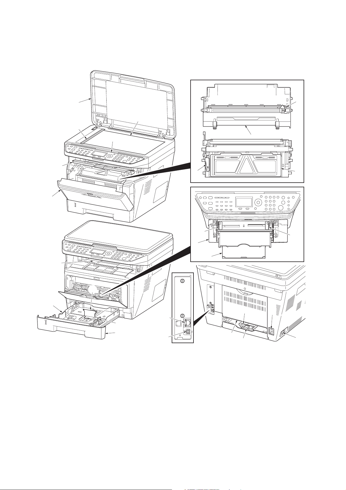
1-1-2 Parts names
(1) Overall
2H9-1
1
2
3
4
5
9
6
16
17
18
11
8
7
10
16
13
14
1. Original cover
2. Platen (contact glass)
3. Original size Indicator plate
4. Operation panel
5. Top cover
6. Front cover
7. Main charger cleaner
8. Drum unit
15
14
20
19
Figure 1-1-1
9. Lock lever
10. Toner container
11. Top tray
12. Paper length guide
13. Paper stopper
14. Paper width guides
15. Cassette
16. Paper width guides (MP tray)
13
21
12
23
22
17. MP (Multi-Purpose) tray
18. MP tray extension
19. USB Interface connector
20. Network Interface connector
21. Rear cover
22. Main power switch
23. Power cord connector
1-1-3
Page 18
2H9-1
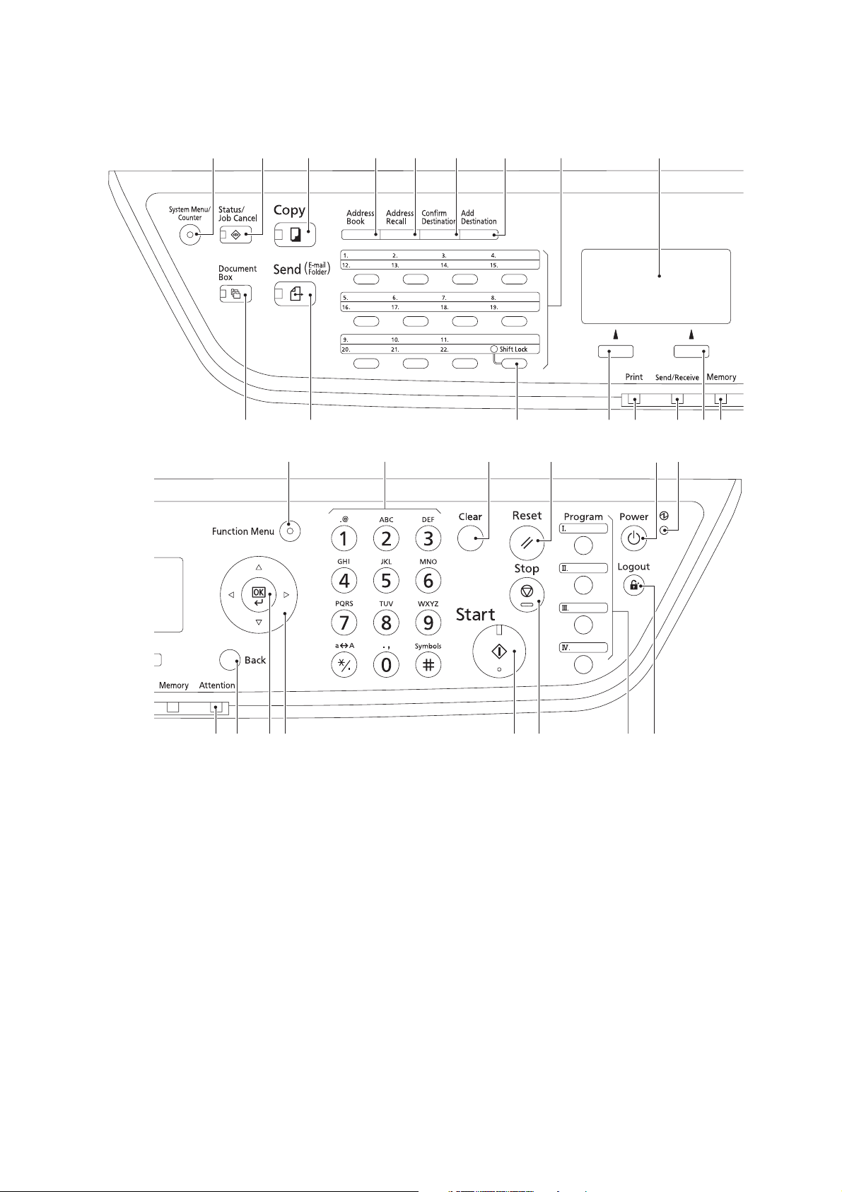
(2) Operation panel
1
10 11 13 14 15 16 1712
32456789
18 19 20 21 22 23
1. System menu/Counter key
(LED)
2. Status/Job Cancel key (LED)
3. Copy key (LED)
4. Address Book key
5. Address Recall key
6. Confirm Destination key
7. Add Destination key
8. One-touch keys
9. Message display
10. Document Box key (LED)
1-1-4
Figure 1-1-2
11. Send key (LED)
12. Shift Lock key (LED)
13. Left Select key
14. Print indicator
15. Send/Receive indicator
16. Right Select key
17. Memory indicator
18. Function Menu key (LED)
19. Numeric keys
20. Clear key
21. Reset key
28 29 30 3127262524
22. Power key
23. Main power indicator
24. Attention indicator
25. Back key
26. OK key
27. Cursor keys
28. Start key (LED)
29. Stop key
30. Program keys
31. Logout key (LED)
Page 19
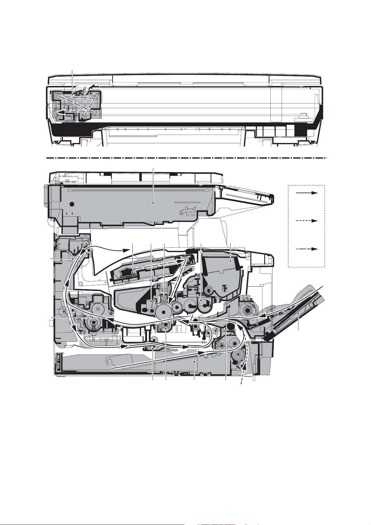
1-1-3 Machine cross section
14
2H9
13
Paper path
11
10
1912
Figure 1-1-3
Paper path
(option)
45678
Light path
2
3
1. Cassette
2. MP tray
3. Paper feed/conveying section
4. Toner container
5. Developing unit
6. Main charger unit
7. Drum unit
8. Laser scanner unit (LSU)
9. Transfer/separation section
10. Fuser section
11. Exit section
12. Duplex/conveying section
13. Scanner section
14. Image scanner unit (ISU)
1-1-5
Page 20

2H9
This page is intentionally left blank.
1-1-6
Page 21
1-2 Installation
1-2-1 Installation environment
1. Temperature: 10 to 32.5°C/50 to 90.5°F
2. Humidity: 15 to 80%RH
3. Power supply:120 V AC, 7.8 A
220 - 240 V AC, 4.0 A
4. Power source frequency: 50 Hz ±0.3%/60 Hz ±0.3%
5. Installation location
Avoid direct sunlight or bright lighting. Ensure that the photoconductor will not be exposed to direct sunlight or
other strong light when removing paper jams.
Avoid locations subject to high temperature and high humidity or low temperature and low humidity; an abrupt
change in the environmental temperature; and cool or hot, direct air.
Avoid places subject to dust and vibrations.
Choose a surface capable of supporting the weight of the machine.
Place the machine on a level surface (maximum allowance inclination: 1
Avoid air-borne substances that may adversely affect the machine or degrade the photoconductor, such as mercury, acidic of alkaline vapors, inorganic gasses, NOx, SOx gases and chlorine-based organic solvents.
Select a well-ventilated location.
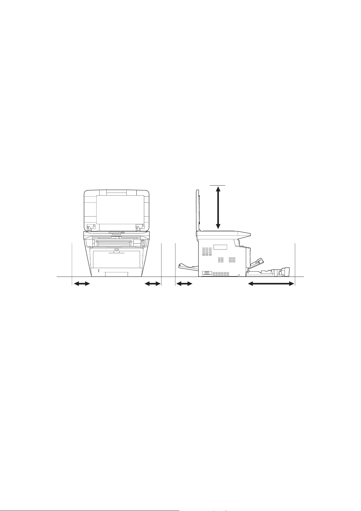
6. Allow sufficient access for proper operation and maintenance of the machine.
°).
2H9
300 mm
300 mm
13/16"
11 13/16"
11
300 mm
300 mm
13/16"
11 13/16"
11
300 mm
300 mm
13/16"
11 13/16"
11
Figure 1-2-1
500 mm
500 mm
11/16"
19 11/16"
19
1000 mm
1000 mm
39
3/8"
39 3/8"
1-2-1
Page 22
2H9-1
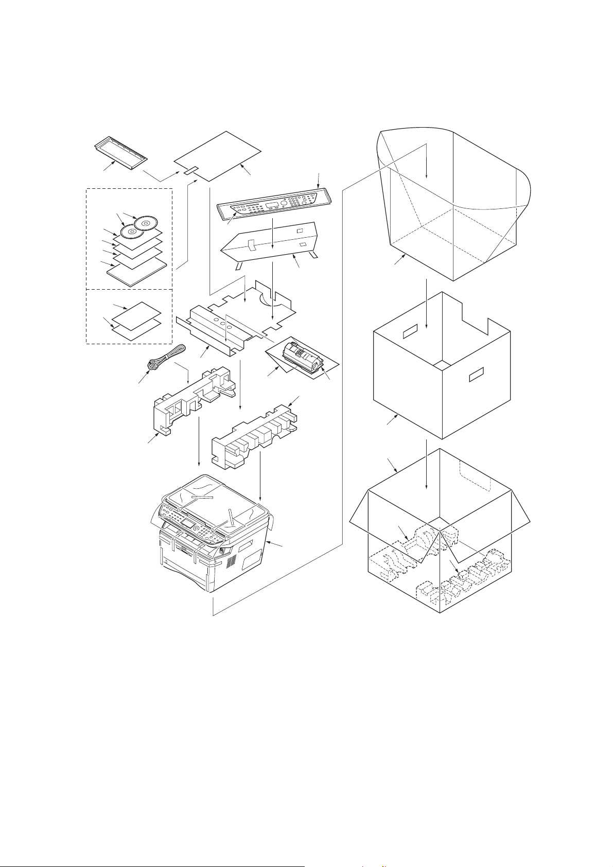
1-2-2 Unpacking
(1) Unpacking
17
120 V AC model
23
18
20
21
22
220-240 V AC model
18
19
12
7
13
16
14
15
9
11
10
8
6
3
2
1. Printer
2. Outer case
3. Inner frame
4. Bottom pad L
5. Bottom pad R
6. Machine cover
7. Top pad L
8. Top pad R
9. Accessory spacer
1-2-2
1
Figure 1-2-2
10. Toner container
11. Plastic bag
12. Power cord
13. Plastic bag (250 × 600)
14. Operation labels
15. Operation label pad
16. Plastic bag (240 × 350)
17. Operation guide holder
18. Operation panel leaflet
4
5
19. EEA information leaflet**
20. Setup guide*
21. Quick guide*
22. Operation guide*
23. CD-ROMs*
* 120 V AC model only.
** 220-240 V AC model only.
Page 23
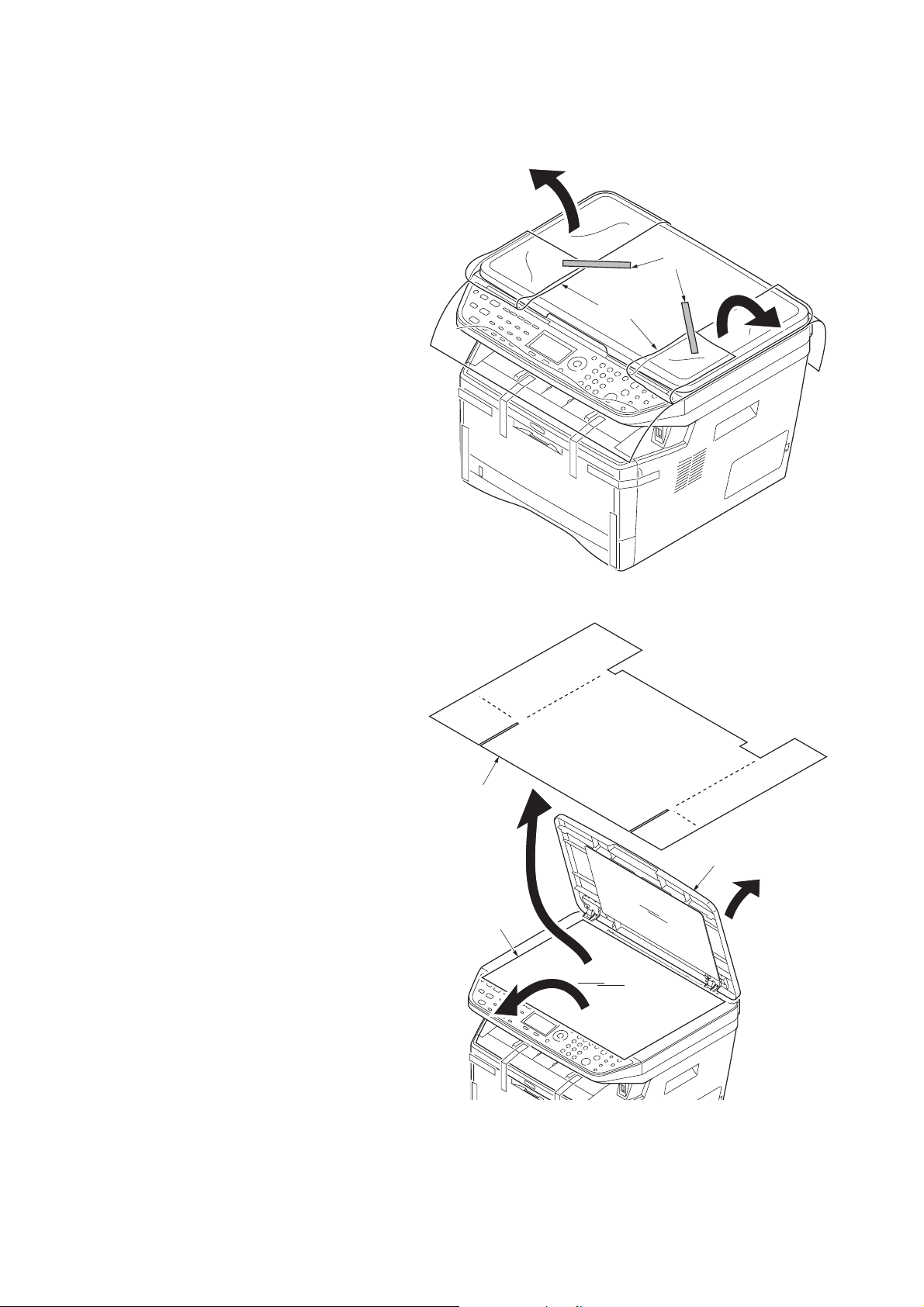
(2) Removing the tapes
<Procedure>
1. Remove two tapes.
2. Open the sheet.
2H9
Ta pe s
Sheet
3. Open the original cover.
4. Remove the sheet.
5. Remove the paper.
Figure 1-2-3
Sheet
Original cover
Paper
Figure 1-2-4
1-2-3
Page 24
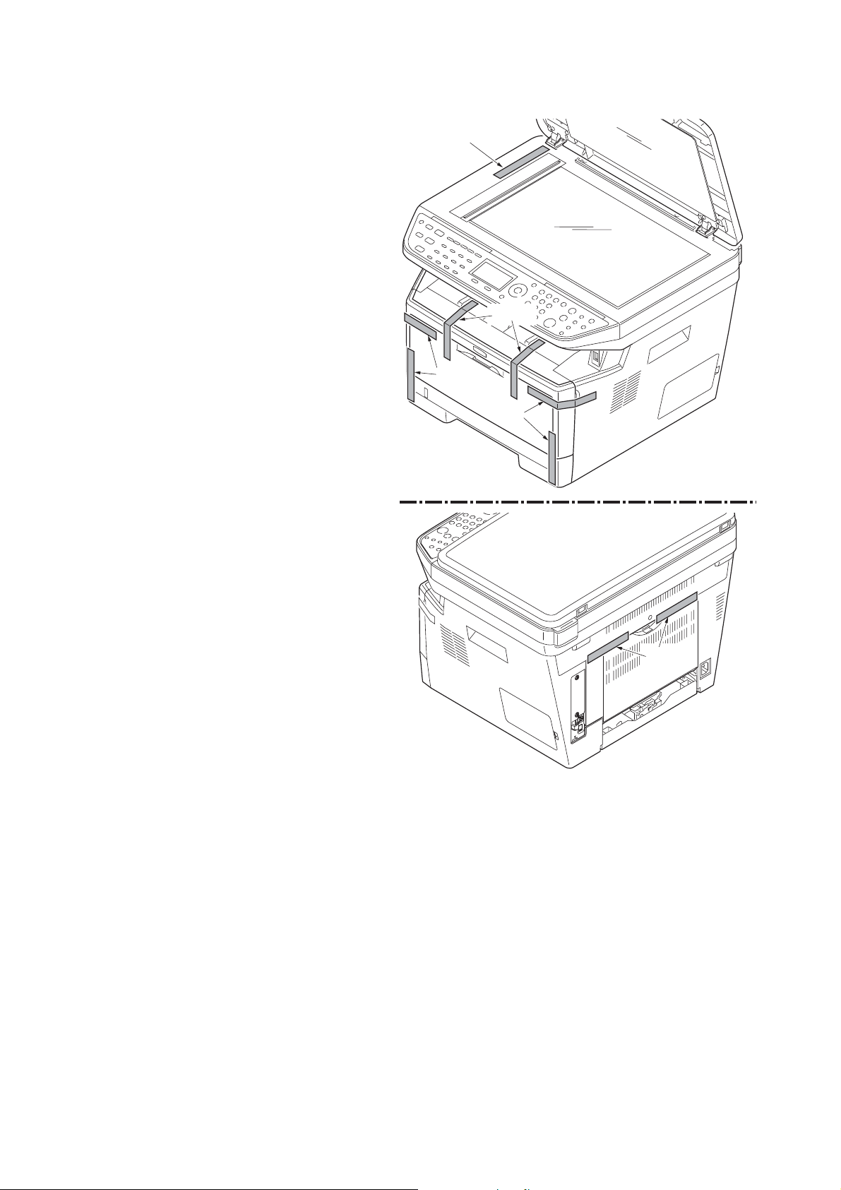
2H9
6. Remove nine tapes.
Ta pe
Ta pe s
Ta pe s
Ta pe s
Figure 1-2-5
Ta pe s
1-2-4
Page 25
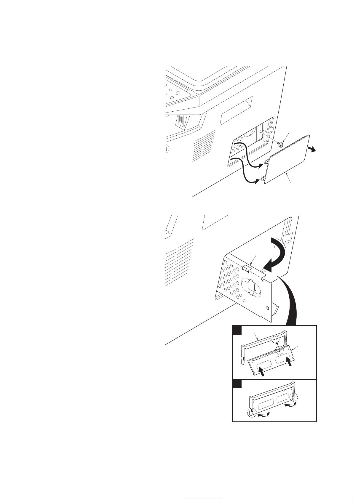
1-2-3 Installing the expansion memory (option)
<Procedure>
1. Turn off the main power switch.
Caution: Do not insert or remove expansion
memory while machine power is on.
Doing so may cause damage to the
machine and the expansion memory.
2. Remove the right side cover.
3. Remove the screw.
2H9
Screw
Right side cover
4. Open the memory slot cover.
5. Insert the expansion memory into the mem-
ory socket so that the notches on the memory align with the corresponding protrusions
in the slot.
6. Close the memory slot cover.
7. Secure the screw.
8. Refit the right side cover.
9. Print a status page to check the memory
expansion.
If memory expansion has been properly performed, information on the installed memory
is printed with the total memory capacity has
been increased. Standard memory capacity
256 MB.
Figure 1-2-6
Memory slot cover
Memory socket
1
Expansion
memory
2
Figure 1-2-7
1-2-5
Page 26

2H9
This page is intentionally left blank.
1-2-6
Page 27
1-3 Maintenance Mode
1-3-1 Maintenance mode
The machine is equipped with a maintenance function which can be used to maintain and service the machine.
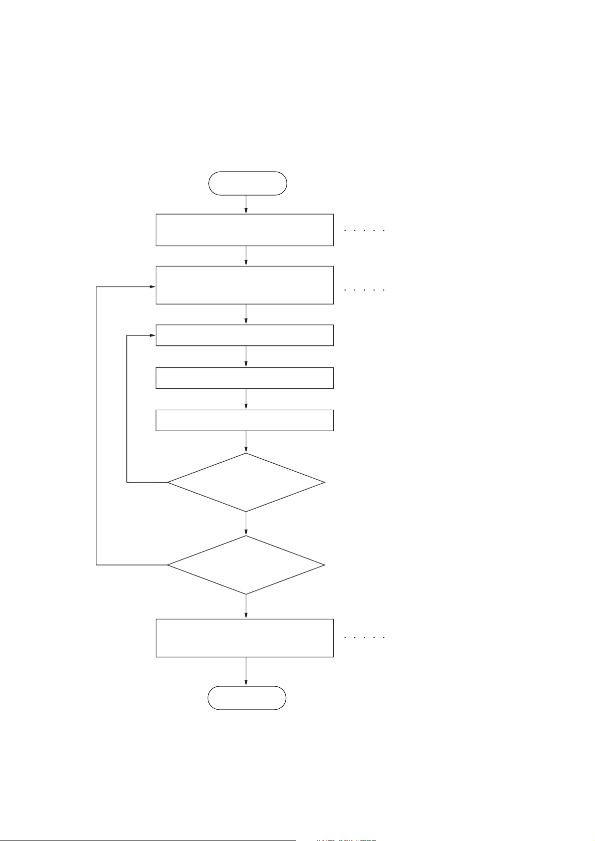
(1) Executing a maintenance item
Start
2H9-1
Yes
Enter “10871087” using
the numeric keys.
Enter the maintenance item
number using the cursor left/right keys
or numeric keys.
Press the start key.
The selected maintenance item is run.
Press the stop key.
Repeat the same
maintenance item?
Maintenance mode is entered.
The maintenance item is
selected.
Yes
No
Run another maintenance
item?
No
Enter “001” using the cursor
left/right keys or numeric keys
and press the start key.
End
Maintenance mode is exited.
1-3-1
Page 28

2H9-1
(2) Maintenance modes item list
Section Item
No.
General U000 Outputting an own-status report -
U001 Exiting the maintenance mode -
U002 Setting the factory default data -
U004 Displaying the machine number -
U019 Displaying the ROM version -
Initialization U021 Initializing counters and mode settings -
Drive, paper
feed, paper
conveying
and cooling
system
Optical U063 Adjusting the shading position 0
High voltage U100 Setting the main high voltage 0
Developing U130 Initial setting for the developing unit -
Fuser and
cleaning
U030 Checking motor operation -
U031 Checking switch/sensor for paper conveying -
U032 Checking clutch operation -
U033 Checking solenoid operation -
U034 Adjusting the print start timing
Adjusting the leading edge registration
Adjusting the center line
U051 Adjusting the deflection in the paper 0/0/0/0/0
U053 Setting the adjustment of the motor speed 0
U065 Adjusting the scanner magnification
Main scanning direction/auxiliary scanning direction 0/0
U066 Adjusting the scanner leading edge registration 0/0
U067 Adjusting the scanner center line 0/0
U068 Adjusting the scanning position for originals from the DP 0/0
U070 Adjusting the DP magnification 0
U071 Adjusting the DP scanning timing 0/0/0/0/0
U072 Adjusting the DP center line 0/0
U073 Checking scanner operation -
U087 Setting DP reading position modification operation 125/125/120
U089 Outputting a MIP-PG pattern -
U101
U111
U113
U144 Setting toner loading operation 1/3/8/20/1/2/3
U157 Checking the developing drive time -
U161 Setting the fuser control temperature 0/0/0/0/0/0/0
U199 Checking the fuser temperature -
Setting the voltage for the primary transfer
Checking/clearing the drum drive time
Performing drum refresh operation
Content of maintenance item Initial
setting*
541/0/0/0
235/0/0/0/0/0/0
OFF/0
0
-
*: Factory initial setting, *1: The item initialized for executing U021
1-3-2
Page 29

2H9-2
Section Item
Operation
panel and
support
equipment
No.
U200 Turning all LEDs on -
U203 Checking DP operation -
U207 Checking the operation panel keys -
Content of maintenance item Initial
setting*
U222 Setting the IC card type -
U223 Operation panel lock -
U243 Checking the operation of the DP motor solenoids and clutch -
U244 Checking the DP sensors -
Mode setting U250 Setting the maintenance cycle 100000
U251 Checking/clearing the maintenance count -
U252 Setting the destination -
U253 Switching between double and single counts Double count
U260 Selecting the timing for copy counting EJECT
U265 Setting OEM purchaser code 0
U278 Setting the delivery date -
U285 Setting service status page ON
U332 Setting the size conversion factor 1.0
U342 Setting the ejection restriction ON
*1
*1
U343 Switching between duplex/simplex copy mode OFF
*1
Image
processing
U345 Setting the value for maintenance due indication 0
U402 Adjusting margins of image printing 30/25/25/50/50
U403 Adjusting margins for scanning an original on the platen 2.0/2.0/2.0/5.0
U404 Adjusting margins for scanning an original from the DP 3.0/2.5/3.0/4.0
U407 Adjusting the leading edge registration for memory image
0
printing
U411 Adjusting the scanner automatically -
U425 Setting the target -
Others U901 Checking copy counts by paper feed locations -
U903 Checking/clearing the paper jam counts -
U904 Checking/clearing the service call counts -
U905 Checking/clearing counts by optional devices -
U908 Checking the total counter value -
U910 Clearing the black ratio data -
U911 Checking/clearing copy counts by paper sizes -
U917 Setting backup data reading/writing -
U920 Checking the copy counts -
U927 Clearing the all copy counts and machine life counts (one
-
time only)
U928 Checking machine life counts -
U942 Setting of deflection for feeding from DP 0/0
U969 Checking of toner area code -
U977 Data capture mode -
U991 Checking the scanner count -
U993 Outputting a VTC-PG pattern -
*1
*1
*1
*: Factory initial setting, *1: The item initialized for executing U021
1-3-3
Page 30
2H9-2
(3) Contents of the maintenance mode items
Maintenance
item No.
U000
Description
Outputting an own-status report
Description
Outputs lists of the current settings of the maintenance items and paper jam and service call occurrences.
Outputs the event log. Also sends output data to the USB memory.
Printing a report is disabled either when a job is remaining in the buffer or when [Pause All Print Jobs] is
pressed to halt printing.
Purpose
To check the current setting of the maintenance items, or paper jam or service call occurrences. Before initializing or replacing the backup RAM, output a list of the current settings of the maintenance items to reenter the
settings after initialization or replacement.
Method
1. Press the start key.
2. Select the item to be output using the cursor up/down keys.
Display Output list
MAINTENANCE List of the current settings of the maintenance modes
EVENT Outputs the event log
ALL Outputs the all reports
3. Press the start key. The interrupt print mode is entered and a list is output.
When A4/Letter paper is available, a report of this size is output. If not, specify the paper feed location.
When output is complete, the screen for selecting an item is displayed.
Method: Send to the USB memory
1. Press the power key on the operation panel, and after verifying the main power indicator has gone off,
switch off the main power switch.
2. Insert USB memory in USB memory slot.
3. Turn the main power switch on.
4. Enter the maintenance item.
5. Press the start key.
6. Select the item to be send.
7. Select [TEXT] or [HTML].
Display Output list
Print Outputs the report
USB (TEXT) Sends output data to the USB memory (text type)
USB (HTML) Sends output data to the USB memory (HTML type)
1-3-4
8. Press the start key.
Output will be sent to the USB memory.
Page 31

2H9-2
Maintenance
item No.
U000
Event log
Description
Event Log
MFP
Firmware version 2H9_2F00.001.177
(1)
(3)
Paper Jam Log
#
Count.
16
9876543
15
666554
14
4988
13
4988
12
4988
11
4988
10
110 3
9
110 3
8
110 3
7
110 3
6
1027
5
1027
4
1027
3
1027
2
550
1
28
(7)
Counter Log
J10:000
(f) (g) (h)
J11:000
J12:000
J20:002
J21:000
J22:000
J30:000
J31:000
Event
Descriprions
10.01.08.01.01
10.01.08.01.02
10.01.08.01.01
10.01.08.01.02
10.01.08.01.01
10.01.08.01.02
10. 01. 08. 01. 01
10.01.08.01.01
(a) (b) (c) (d) (e)
10.01.08.01.01
12.03.08.01.01
12.03.08.01.01
12.03.08.01.01
12.03.0A.01.01
12.03.08.01.01
12.03.08.01.02
12.03.0A.01.01
12.03.08.01.01
J73:000
J74:000
J78:000
2009.04.17
(2)
C0100:001
C0110:001
C0120:001
C0150:001
C0170:001
C0420:001
C2000:001
C2610:001
C2620:001
(4)
Service Call Log
#
Count.
8
7881214
7
578944
6
5296
5
5295
4
2099
3
1054
2
809
1
30
Maintenance Log
(5)
#
Count.
8
9045571
7
704511
6
7045
5
3454
4
3454
3
3454
2
417
1
35
Unknown toner Log
(6)
#
Count.
5
3454
4
3454
3
3454
2
417
1
35
M00:01
Service Code
01.0060
01.0120
01.4000
01.3100
01.2000
01.2000
01.2200
01.2500
Item
01.00
02.00
01.00
02.00
01.00
02.00
01.00
02.00
Item
01.00
01.00
01.00
01.00
01.00
Detail of event log
No. Items Description
(1) System version
(2) System date
(3) Paper Jam Log # Count. Event
Remembers 1 to 16 of
occurrence. If the
occurrence of the previ-
The total page count at
the time of the paper
jam.
ous paper jam is less
than 16, all of the paper
jams are logged. When
the occurrence
excesseds 16, the oldest occurrence is
removed.
Log code (2 digit, hexadecimal, 5 categories)
(a) Cause of a paper
jam
(b) Paper source
(c) Paper size
(d) Paper type
(e) Paper eject
1-3-5
Page 32

2H9-3
Maintenance
item No.
U000
Description
No. Items Description
(3)
Paper Jam Log (a) Cause of paper jam (Hexadecimal)
cont.
10: Paper does not arrive at the registration sensor. (MP tray) [42]
10: Paper does not arrive at the registration sensor. (Cassette 1) [31]
10: Paper does not arrive at the registration sensor. (Cassette 2) [31]
10: Paper does not arrive at the registration sensor. (Cassette 3) [31]
10: Paper does not arrive at the registration sensor. (Duplex conveying)
[49]
11: Paper does not pass the registration sensor. [48]
12: Paper remains at the registration sensor when power is turned on. [48]
20: Paper does not arrive at the exit sensor. [48]
21: Paper does not pass the exit sensor. [47]
22: Paper remains at the exit sensor when power is turned on. [47]
30: Paper does not arrive at the paper feeder 1’s PF paper feed sensor.
(Cassette 2) [32]
30: Paper does not arrive at the paper feeder 1’s PF paper feed sensor.
(Cassette 3) [33]
31: Paper does not pass the paper feeder 1’s PF paper feed sensor.
(Cassette 2) [32]
32: Paper remains at the paper feeder 1’s PF paper feed sensor when
power is turned on. (Cassette 2) [32]
40: Paper does not arrive at the paper feeder 2’s PF paper feed sensor.
(Cassette 3) [33]
41: Paper does not pass the paper feeder 2’s PF paper sensor.
(Cassette 3) [33]
42: Paper remains at the paper feeder 2’s PF paper feed sensor when
power is turned on. (Cassette 3) [33]
70: No original feed. (DP) [50]
71: An original jam in the original conveying section 1. (DP) [50]
72: An original jam in the original conveying section 2. (DP) [50]
73: An original jam in the original switchback section. (DP) [50]
74: An original jam in the original switchback/feed section. (DP) [50]
78: Top cover open. (DP) [50]
A1: Paper does not arrive at the exit sensor. [47]
A3: Paper does not pass the exit sensor. [49]
E0: Paper misfeed occurs due to forced stop when an error occurs during
printing. (such as opening of a cover) [00]
F0 to FE: Paper misfeed by another cause. [00]
1-3-6
Note:
Values (hexadecimal) within [ ] indicate paper misfeed locations.
Page 33

2H9-3
Maintenance
item No.
U000
Description
No. Items Description
(3)
Paper Jam Log
cont.
(g)
(h)
[47]
[50]
Printer
(c)
[48]
(d)
[49]
(a)
(b)
[31]
(e)
Paper feeder 1
(option)
Paper feeder 2
(option)
(f)
(f)
[32]
(e)
[33]
DP
Sensor
(a) Registration sensor
(b) Paper sensor
(c) MP paper sensor
(d) Paper exit sensor
(e) PF paper feed sensor
(f) PF paper sensor
(g) DP original sensor
(h) DP timing sensor
[42]
Paper jam location
[31] Cassette 1
[32] Cassette 2
[33] Cassette 3
[42] MP tray
[47] Fuser/Exit section
[48] Printer inside
[49] Duplex section
[50] DP
(b) Detail of paper source (Hexadecimal)
00: MP tray
01: Cassette 1
02: Cassette 2 (paper feeder)
03: Cassette 3 (paper feeder)
04 to 09: Reserved
1-3-7
Page 34

2H9-3
Maintenance
item No.
U000
Description
No. Items Description
(3)
Paper Jam Log (c) Detail of paper size (Hexadecimal)
cont.
01: Monarch
02: Business
03: International DL
04: International C5
05: Executive
06: Letter-R
86: Letter-E
07: Legal
08: A4R
88: A4E
09: B5R
89: B5E
0A: A3
0B: B4
(d) Detail of paper type (Hexadecimal)
01: Plain
02: Transparency
03: Preprinted
04: Labels
05: Bond
06: Recycled
07: Vellum
08: Rough
09: Letterhead
0C: Ledger
0D: A5
0E: A6
0F: B6
10: Commercial #9
11: Commercial #6
12: ISO B5
13: Custom size
1E: C4
1F: Postcard
20: Reply-paid postcard
21: Oficio II
22: Special 1
23: Special 2
0A: Color
0B: Prepunched
0C: Envelope
0D: Cardstock
0E: Coated
0F: 2nd side
10: Media 16
11: High quality
24: A3 wide
25: Ledger wide
26: Full bleed paper
(12 x 8)
27: 8K
28: 16K-R
A8: 16K-E
32: Statement-R
B2: Statement-E
33: Folio
34: Western type 2
35: Western type 4
15: Custom 1
16: Custom 2
17: Custom 3
18: Custom 4
19: Custom 5
1A: Custom 6
1B: Custom 7
1C: Custom 8
(e) Detail of paper exit location (Hexadecimal)
01: Face down (FD)
(4) Service Call Log # Count. Service Code
Remembers 1 to 8 of
occurrence of self diagnostics error. If the
occurrence of the previous diagnostics error is
less than 8, all of the
diagnostics errors are
logged.
The total page count at
the time of the self
diagnostics error.
Self diagnostic error
code
(See page 1-4-3)
Example:
01.6000
01: Self diagnostic
error
6000: Self diagnostic
error code number
1-3-8
Page 35

2H9-3
Maintenance
item No.
U000
Description
No. Items Description
(5) Maintenance Log # Count. Item
Remembers 1 to 8 of
occurrence of replacement. If the occurrence
of the previous replacement of toner container
is less than 8, all of the
occurrences of replacement are logged.
(6) Unknown Toner Log # Count. Item
Remembers 1 to 5 of
occurrence of unknown
toner detection. If the
occurrence of the previous unknown toner
detection is less than 5,
all of the unknown
toner detection are
logged.
The total page count at
the time of the replacement of the toner container.
The total page count at
the time of the [Toner
Empty] error with using
an unknown toner container.
Code of maintenance
replacing item (1 byte,
2 categories)
First byte
(Replacing item)
01: Toner container
02: Maintenance kit
Second byte
(Type of replacing item)
00: Black
01: MK-130/MK-132
Unknown toner log
code (1 byte, 2 categories)
First byte
01: Fixed (Toner container)
Second byte
00: Fixed (Black)
(7) Counter Log
Comprised of three
log counters including paper jams, self
diagnostics errors,
and replacement of
the toner container.
Completion
Press the stop key. The screen for selecting a maintenance item No. is displayed.
(f) Paper jam (g) Self diagnostic error (h) Maintenance item
Indicates the log
counter of paper jams
depending on location.
Refer to Paper Jam
Log.
All instances including
those are not occurred
are displayed.
Indicates the log
counter of self diagnostics errors depending
on cause. (See page 14-3)
Example:
C6000: 4
Self diagnostics error
6000 has happened
four times.
replacing
Indicates the log
counter depending on
the maintenance item
for maintenance.
T: Toner container
00: Black
M: Maintenance kit
00: MK-130/MK-132
Example:
T00: 1
The toner container has
been replaced once.
1-3-9
Page 36

2H9-2
Maintenance
item No.
U001
U002
U004
U019
Description
Exiting the maintenance mode
Description
Exits the maintenance mode and returns to the normal copy mode.
Purpose
To exit the maintenance mode.
Method
Press the start key. The normal copy mode is entered.
Setting the factory default data
Description
Restores the machine conditions to the factory default settings.
Purpose
To move the mirror frame of the scanner to the position for transport (position in which the frame can be fixed).
Method
1. Press the start key.
2. Select [MODE1(ALL)] using the cursor up/down keys.
3. Press the start key.
The mirror frame of the scanner returns to the position for transport.
4. Turn the main power switch off and on.
An error code is displayed in case of an initialization error. Refer to the table of the error codes on P.1-3-11.
When errors occurred, turn main power switch off then on, and execute initialization using maintenance
item U002.
Displaying the machine number
Description
Displays the machine number.
Purpose
To check the machine number.
Method
Press the start key. The currently machine number is displayed.
Completion
Press the stop key. The screen for selecting a maintenance item No. is displayed.
Displaying the ROM version
Description
Displays the part number of the ROM fitted to each PWB.
Purpose
To check the part number or to decide, if the newest version of ROM is installed.
Method
1. Press the start key. The ROM version are displayed.
2. Change the screen using the cursor up/down keys.
1-3-10
Display Description
MAIN Control PWB ROM
MMI Operation panel PWB ROM
ENGINE Engine ROM
ENGINE BOOT Engine booting
CASS 2 Optional paper feeder main PWB ROM
CASS 3 Optional paper feeder main PWB ROM
SCANNER Scanner PWB ROM
SCANNER BOOT Scanner PWB booting
OPTION LANGUAGE Optional language ROM
Completion
Press the stop key. The screen for selecting a maintenance item No. is displayed.
Page 37

2H9-1
Maintenance
item No.
U021
Description
Initializing counters and mode settings
Description
Initializes all settings, except those pertinent to the type of machine, namely each counter, service call history
and mode setting. Also initializes backup RAM according to region specification selected in maintenance item
U252 Setting the destination.
Refer to *1 of the maintenance mode item list about the item initialized.
Purpose
To return the machine settings to their factory default.
Method
1. Press the start key.
2. Select [EXECUTE] using the cursor up/down keys.
3. Press the start key. All data other than that for adjustments due to variations between machines is initialized based on the destination setting.
4. Turn the main power switch off and on.
An error code is displayed in case of an initialization error.
When errors occurred, turn main power switch off then on, and execute initialization using maintenance
item U021.
Error codes
Codes Description
ERROR 01 Configuration initialization error
ERROR 02 Counter initialization error
ERROR 03 One-touch initialization error
ERROR 04 Panel program initialization error
ERROR 05 Event log initialization error
ERROR 06 Account initialization error
ERROR 07 Address book initialization error
ERROR 08 Department initialization error
ERROR 09 Document box initialization error
ERROR 0a Permissibility initialization error
ERROR 0b Job log initialization error
ERROR 20 Engine initialization error
ERROR 40 Scanner initialization error
1-3-11
Page 38

2H9-1
Maintenance
item No.
U030
U031
Description
Checking motor operation
Description
Drives each motor.
Purpose
To check the operation of each motor.
Method
1. Press the start key.
2. Select the motor to be operated using the cursor up/down keys.
3. Press the start key. The operation starts.
Display Operation
MAIN Main motor operates
PAPER FEEDER 1 PF paper feed motor* operates
PAPER FEEDER 2 PF paper feed motor* operates
*: Option.
4. To stop operation, press the stop key.
Completion
Press the stop key. The screen for selecting a maintenance item No. is displayed.
Checking switch/sensor for paper conveying
Description
Displays the on-off status of each paper detection switch/sensor on the paper path.
Purpose
To check if the switch/sensor for paper conveying operate correctly.
Method
1. Press the start key.
2. Turn each switch/sensor on and off manually to check the status.
When a switch/sensor is detected to be in the ON position, the display for that switch/sensor will be “1”.
Display Switch and sensors
WHOLE 0000Cassette switch/Paper sensor/MP paper sensor/Registration sensor
EXIT 0 Exit sensor
PAPER FEED 1 000PF cassette switch*/PF paper sensor*/PF paper feed sensor*
PAPER FEED 2 000PF cassette switch*/PF paper sensor*/PF paper feed sensor*
*: Option.
Completion
Press the stop key. The screen for selecting a maintenance item No. is displayed.
1-3-12
Page 39

2H9-1
Maintenance
item No.
U032
U033
Description
Checking clutch operation
Description
Turns each clutch on.
Purpose
To check the operation of each clutch.
Method
1. Press the start key.
2. Select the clutch to be operated using the cursor up/down keys.
3. Press the start key. The clutch turns on.
Display Clutches
FEED CL Paper feed clutch operates
REG CL Registration clutch operates
DLP CL Developing clutch operates
FEED CL(PF1) PF paper feed clutch* operates
TRANS CL(PF1) PF paper conveying clutch* operates
FEED CL(PF2) PF paper feed clutch* operates
TRANS CL(PF2) PF paper conveying clutch* operates
*: Option.
4. To stop driving motors, press the stop key.
Completion
Press the stop key. The screen for selecting a maintenance item No. is displayed.
Checking solenoid operation
Description
Applies current to each solenoid in order to check its ON status.
Purpose
To check the operation of each solenoid.
Method
1. Press the start key.
2. Select the solenoid to be operated using the cursor up/down keys.
3. Press the start key. The solenoid turns on.
Display Solenoids
MPF SOL MP paper feed solenoid operates
DU SOL Duplex solenoid operates
FD SOL Face down solenoid operation
*Option.
4. To stop driving motors, press the stop key.
Completion
Press the stop key. The screen for selecting a maintenance item No. is displayed.
1-3-13
Page 40

2H9-1
Maintenance
item No.
U034
Description
Adjusting the print start timing
Description
Adjusts the leading edge registration or center line.
Purpose
Make the adjustment if there is a regular error between the leading edges of the copy image and original.
Make the adjustment if there is a regular error between the center lines of the copy image and original.
Caution
Before performing this adjustment, perform the procedure under section “U053 Setting the adjustment of the
motor speed”.
Method
1. Press the start key.
2. Select the item to be adjusted using the cursor up/down keys.
3. Press the start key.
Display Description
LSU OUT TOP Leading edge registration adjustment
LSU OUT LEFT Center line adjustment
Adjustment: Leading edge registration adjustment
1. Select the item to be adjusted using the cursor up/down keys.
Display Description Setting
range
TOP Adjustment of reference value
0 to 1180
Initial
setting
Change in
value per step
541 0.04 mm
MP TRAY Paper feed from MP tray* -70 to 70 0 0.04 mm
CASSETTE Paper feed from cassette* -70 to 70 0 0.04 mm
DUPLEX Duplex mode (second side)* -70 to 70 0 0.04 mm
*: Setting the difference value from reference value
2. Press the system menu/counter key.
3. Press the start key to output a test pattern.
4. Press the system menu/counter key.
5. Change the setting value using the cursor left/right keys or numeric keys.
Perform adjustment so that the image fits in the middle of the page.
For output example 1, decrease the value. For output example 2, increase the value.
Center line in
vertical direction
Correct image Output
example 1
Output
example 2
Figure 1-3-1
6. Press the start key. The value is set.
Caution
Check the copy image after the adjustment. If the image is still incorrect, perform the following adjustments in
maintenance mode.
U034
U066
(P.1-3-20)
U071
(P.1-3-24)
1-3-14
Page 41

2H9-1
Maintenance
item No.
U034
Description
Adjustment: Center line adjustment
1. Select the item to be adjusted using the cursor up/down keys.
Display Description Setting
range
Initial
setting
LEFT Adjustment of reference value 0 to 1180 235 0.04 mm
MP TRAY Paper feed from MP tray* -70 to 70 0 0.04 mm
CASSETTE 1 Paper feed from cassette 1* -70 to 70 0 0.04 mm
CASSETTE 2 Paper feed from optional cassette 2* -70 to 70 0 0.04 mm
CASSETTE 3 Paper feed from optional cassette 3* -70 to 70 0 0.04 mm
DUPLEX Duplex mode (second side)* -70 to 70 0 0.04 mm
*: Setting the difference value from reference value
2. Press the system menu/counter key.
3. Press the start key to output a test pattern.
4. Press the system menu/counter key.
5. Change the setting value using the cursor left/right keys or numeric keys.
For output example 1, decrease the value. For output example 2, increase the value.
Center line of printing
Change in
value per step
Correct image Output
example 1
Output
example 2
Figure 1-3-2
6. Press the start key. The value is set.
Caution
Check the copy image after the adjustment. If the image is still incorrect, perform the following adjustments in
maintenance mode.
U034
U067
(P.1-3-21)
U072
(P.1-3-26)
Completion
Press the stop key. The screen for selecting a maintenance item No. is displayed.
1-3-15
Page 42

2H9-2
Maintenance
item No.
U051
Description
Adjusting the deflection in the paper
Description
Adjusts the deflection in the paper.
Purpose
Make the adjustment if the leading edge of the copy image is missing or varies randomly, or if the copy paper
is Z-folded.
Adjustment
1. Press the start key.
2. Select the item to be adjusted using the cursor up/down keys.
Display Description Setting
range
Initial
setting
Change in
value per step
DELAY BASE Adjustment of deflection in the paper -128 to 127 0 1 mm
REGIST CAS1 Paper feed from cassette -128 to 127 0 1 mm
REGIST CAS2 Paper feed from optional cassette -128 to 127 0 1 mm
REGIST CAS3 Paper feed from optional cassette -128 to 127 0 1 mm
DUPLEX Duplex mode (second side) -128 to 127 0 1 mm
3. Press the system menu/counter key.
4. Place an original and press the start key to make a test copy.
5. Press the system menu/counter key.
6. Change the setting value using the cursor left/right keys or numeric keys.
For output example 1, increase the value. For output example 2, decrease the value.
The greater the value, the larger the deflection; the smaller the value, the smaller the deflection.
Original Copy
7. Press the start key. The value is set.
8. Turn the main power switch off and on.
example 1
Figure 1-3-3
Copy
example 2
1-3-16
Page 43

2H9-2
250
Maintenance
item No.
U053
Description
Setting the adjustment of the motor speed
Description
Performs fine adjustment of the speeds of the motor.
Purpose
To adjust the speed of the motor when the magnification in the auxiliary scanning direction is not correct.
Method
1. Press the start key.
Display Description Setting
range
Initial
setting
Change in
value per step
MAIN MOTOR Main motor speed adjustment -50 to 50 0 0.5%
Adjustment
1. Press the system menu/counter key.
2. Press the start key to output a VTC pattern.
100
150
200
250
a
Correct value: a = 250 ± 1.0 mm
Figure 1-3-4
3. Press the system menu/counter key.
4. Change the setting value using the cursor left/right keys or numeric keys.
Increasing the setting makes the image longer in the auxiliary scanning direction, and decreasing it
makes the image shorter in the auxiliary scanning direction.
5. Press the start key. The value is set.
6. Turn the main power switch off and on.
1-3-17
Page 44

2H9-1
Maintenance
item No.
U063
Description
Adjusting the shading position
Description
Changes the shading position of the scanner.
Purpose
Used when white lines continue to appear longitudinally on the image after the shading plate is cleaned. This
is due to flaws or stains inside the shading plate. To prevent this problem, the shading position should be
changed so that shading is possible without being affected by the flaws or stains.
Method
1. Press the start key.
2. Change the setting using the cursor left/right keys or numeric keys.
Description Setting range Initial setting Change in value per step
Shading position -32 to 20 0 0.086 mm
Increasing the setting moves the shading position toward the machine left, and decreasing it moves the
position toward the machine right.
3. Press the start key. The value is set.
Supplement
While this maintenance item is being executed, copying from an original is available in interrupt copying mode
(which is activated by pressing the system menu/counter key).
Completion
Press the stop key. The screen for selecting a maintenance item No. is displayed.
1-3-18
Page 45

2H9-1
Maintenance
item No.
U065
Description
Adjusting the scanner magnification
Description
Adjusts the magnification of the original scanning.
Purpose
Make the adjustment if the magnification in the main scanning direction is incorrect.
Make the adjustment if the magnification in the auxiliary scanning direction is incorrect.
Caution
Adjust the magnification of the scanner in the following order.
U053
(P.1-3-17)
U065
(main scanning
direction)
U065
(auxiliary scanning
direction)
U067
(P.1-3-21)
Method
1. Press the start key.
2. Select the item to be adjusted using the cursor up/down keys.
Display Description Setting
range
Y SCAN ZOOM Scanner magnification in the main
-32 to 127 0 0.1%
Initial
setting
scanning direction
X SCAN ZOOM Scanner magnification in the auxil-
-25 to 25 0 0.1%
iary scanning direction
Adjustment: Main scanning direction
1. Press the system menu/counter key.
2. Place an original and press the start key to make a test copy.
3. Press the system menu/counter key.
4. Change the setting value using the cursor left/right keys or numeric keys.
For copy example 1, increase the value. For copy example 2, decrease the value.
U070
(P.1-3-23)
Change in
value per step
Original Copy
example 1
Copy
example 2
Figure 1-3-5
5. Press the start key. The value is set.
Adjustment: Auxiliary scanning direction
1. Press the system menu/counter key.
2. Place an original and press the start key to make a test copy.
3. Press the system menu/counter key.
4. Change the setting value using the cursor left/right keys or numeric keys.
For copy example 1, increase the value. For copy example 2, decrease the value.
Original Copy
example 1
Copy
example 2
Figure 1-3-6
5. Press the start key. The value is set.
Completion
Press the stop key. The screen for selecting a maintenance item No. is displayed.
1-3-19
Page 46

2H9-1
Maintenance
item No.
U066
Description
Adjusting the scanner leading edge registration
Description
Adjusts the scanner leading edge registration of the original scanning.
Purpose
Make the adjustment if there is a regular error between the leading edges of the copy image and original.
Adjustment
1. Press the start key.
2. Select the item to be adjusted using the cursor up/down keys.
Display Description Setting
range
Initial
setting
Change in
value per step
FRONT Scanner leading edge registration -45 to 45 0 0.086 mm
TAIL Scanner leading edge registration
-45 to 45 0 0.086 mm
(rotate copying)
3. Press the system menu/counter key.
4. Place an original and press the start key to make a test copy.
5. Press the system menu/counter key.
6. Change the setting value using the cursor left/right keys or numeric keys.
For copy example 1, increase the value. For copy example 2, decrease the value.
Scanner leading edge registration
Original
Copy
example 1
Copy
example 2
Figure 1-3-7
7. Press the start key. The value is set.
Caution
Check the copy image after the adjustment. If the image is still incorrect, perform the following adjustments in
maintenance mode.
U066
U403
(P.1-3-43)
U071
(P.1-3-24)
U404
(P.1-3-44)
Completion
Press the stop key. The screen for selecting a maintenance item No. is displayed.
1-3-20
Page 47

2H9-1
Maintenance
item No.
U067
Description
Adjusting the scanner center line
Description
Adjusts the scanner center line of the original scanning.
Purpose
Make the adjustment if there is a regular error between the center lines of the copy image and original.
Adjustment
1. Press the start key.
2. Select the item to be adjusted using the cursor up/down keys.
Display Description Setting
range
Initial
setting
Change in
value per step
FRONT Scanner center line -70 to 70 0 0.085 mm
ROTATE Scanner center line (rotate copying) -40 to 40 0 0.085 mm
3. Press the system menu/counter key.
4. Place an original and press the start key to make a test copy.
5. Press the system menu/counter key.
6. Change the setting value using the cursor left/right keys or numeric keys.
For copy example 1, decrease the value. For copy example 2, increase the value.
Scanner center line
Original Copy
example 1
Copy
example 2
Figure 1-3-8
7. Press the start key. The value is set.
Caution
Check the copy image after the adjustment. If the image is still incorrect, perform the following adjustments in
maintenance mode.
U067
U403
(P.1-3-43)
U072
(P.1-3-26)
U404
(P.1-3-44)
Completion
Press the stop key. The screen for selecting a maintenance item No. is displayed.
1-3-21
Page 48

2H9-1
Maintenance
item No.
U068
Description
Adjusting the scanning position for originals from the DP
Description
Adjusts the position for scanning originals from the DP. Performs the test copy at the four scanning positions
after adjusting.
Purpose
Used when the image fogging occurs because the scanning position is not proper when the DP is used. Run
U071 to adjust the timing of DP leading edge when the scanning position is changed.
Setting
1. Press the start key.
Display Description Setting
range
DP READ Starting position adjustment for
scanning originals
BLACK LINE Scanning position for the test copy
originals
2. Select [DP READ].
3. Change the setting using the cursor left/right keys or numeric keys.
When the setting value is increased, the scanning position moves to the right and it moves to the left
when the setting value is decreased.
4. Press the start key. The value is set.
5. Select [BLACK LINE] using the cursor up/down keys.
6. Select the scanning position using the cursor left/right keys or numeric keys.
7. Press the start key. The value is set.
8. Set the original (the one which density is known) in the DP and press the system menu/counter key. The
screen for the test copy mode is displayed.
9. Press the start key. Test copy is executed.
10. Perform the test copy at each scanning position with the setting value from 0 to 3 and check that no
black line appears and the image is normally scanned.
Completion
Press the stop key. The screen for selecting a maintenance item No. is displayed.
-33 to 33 0 0.086 mm
0 to 3 0 0.22 mm
Initial
setting
Change in
value per step
1-3-22
Page 49

2H9-1
Maintenance
item No.
U070
Description
Adjusting the DP magnification
Description
Adjusts the DP original scanning speed.
Purpose
Make the adjustment if the magnification is incorrect in the auxiliary scanning direction when the DP is used.
Method
1. Press the start key.
Display Description Setting
range
CONVEY SPEED Magnification in the auxiliary scanning
-25 to 25 0 0.1%
Initial
setting
Change in
value per step
direction
Adjustment
1. Press the system menu/counter key.
2. Place an original on the DP and press the start key to make a test copy.
3. Press the system menu/counter key.
4. Change the setting value using the cursor left/right keys or numeric keys.
For copy example 1, increase the value. For copy example 2, decrease the value.
Original Copy
example 1
Copy
example 2
Figure 1-3-9
5. Press the start key. The value is set.
Caution
Check the copy image after the adjustment. If the image is still incorrect, perform the following adjustments in
maintenance mode.
U070
U071
(P.1-3-24)
U404
(P.1-3-44)
Completion
Press the stop key. The screen for selecting a maintenance item No. is displayed.
1-3-23
Page 50

2H9-1
Maintenance
item No.
U071
Description
Adjusting the DP scanning timing
Description
Adjusts the DP original scanning timing.
Purpose
Make the adjustment if there is a regular error between the leading or trailing edges of the original and the
copy image when the DP is used.
Method
1. Press the start key.
2. Select the item to be adjusted using the cursor up/down keys.
Display Description Setting
range
Initial
setting
Change in
value per step
FRONT HEAD Leading edge registration (first page) -32 to 32 0 0.196 mm
FRONT TAIL Trailing edge registration (first page) -32 to 32 0 0.196 mm
BACK HEAD Leading edge registration (second page) -45 to 45 0 0.196 mm
BACK TAIL Trailing edge registration (second page) -45 to 45 0 0.196 mm
ROTATE Leading edge registration (rotate copying) -128 to 127 0 0.196 mm
Adjustment: Leading edge registration
1. Press the system menu/counter key.
2. Place an original on the DP and press the start key to make a test copy.
3. Press the system menu/counter key.
4. Change the setting value using the cursor left/right keys or numeric keys.
For copy example 1, increase the value. For copy example 2, decrease the value.
Original Copy
example 1
Copy
example 2
Figure 1-3-10
5. Press the start key. The value is set.
Caution
Check the copy image after the adjustment. If the image is still incorrect, perform the following adjustments in
maintenance mode.
U071
U404
(P.1-3-44)
1-3-24
Page 51

2H9-1
Maintenance
item No.
U071
Description
Adjustment: Trailing edge registration
1. Press the system menu/counter key.
2. Place an original on the DP and press the start key to make a test copy.
3. Press the system menu/counter key.
4. Change the setting value using the cursor left/right keys or numeric keys.
For copy example 1, increase the value. For copy example 2, decrease the value.
Original
Copy
example 1
Copy
example 2
Figure 1-3-11
5. Press the start key. The value is set.
Caution
Check the copy image after the adjustment. If the image is still incorrect, perform the following adjustments in
maintenance mode.
U071
U404
(P.1-3-44)
Completion
Press the stop key. The screen for selecting a maintenance item No. is displayed.
1-3-25
Page 52

2H9-1
Maintenance
item No.
U072
Description
Adjusting the DP center line
Description
Adjusts the scanning start position for the DP original.
Purpose
Make the adjustment if there is a regular error between the centers of the original and the copy image when
the DP is used.
Adjustment
1. Press the start key.
2. Select the item to be adjusted using the cursor up/down keys.
Display Description Setting
range
Initial
setting
Change in
value per step
FRONT Center line (first page) -39 to 39 0 0.085 mm
BACK Center line (second page) -39 to 39 0 0.085 mm
ROTATE Center line (rotate copying) -39 to 39 0 0.085 mm
3. Press the system menu/counter key.
4. Place an original on the DP and press the start key to make a test copy.
5. Press the system menu/counter key.
6. Change the setting value using the cursor left/right keys or numeric keys.
For copy example 1, increase the value. For copy example 2, decrease the value.
Reference
Original Copy
example 1
Copy
example 2
Figure 1-3-12
7. Press the start key. The value is set.
Caution
Check the copy image after the adjustment. If the image is still incorrect, perform the following adjustments in
maintenance mode.
U072
U404
(P.1-3-44)
Completion
Press the stop key. The screen for selecting a maintenance item No. is displayed.
1-3-26
Page 53

2H9-1
Maintenance
item No.
U073
Description
Checking scanner operation
Description
Simulates the scanner operation under arbitrary conditions.
Purpose
To check scanner operation.
Start
1. Press the start key.
2. Select the item to be operated using the cursor up/down keys.
Display Description
SCANNER MOTOR Scanner operation
HOME POSITION Home position operation
DUST CHECK Dust adhesion check operation with lamp on
DP READING DP scanning position operation
Setting: SCANNER MOTOR
1. Select [SCANNER MOTOR].
2. Select the item to be set using the cursor up/down keys.
3. Change the setting using the cursor left/right keys.
Display Operating conditions Setting range
ZOOM Magnification 25 to 400%
SIZE Original size See below.
LAMP On and off of the exposure lamp 0 (off) or 1 (on)
Original sizes for each setting in SIZE
Setting Paper size Setting Paper size
5000 A4 7800 Folio
6100 B5R 8400 8 1/2" x 14"
5000 A5R 6600 8
1/2" x 11"
4. Select [EXECUTE] using the cursor up/down keys.
5. Press the start key. Scanning starts under the selected conditions.
6. To stop operation, press the stop key.
Method: HOME POSITION
1. Select [HOME POSITION].
2. Press the start key.
The mirror frame of the scanner moves to the home position.
Method: DUST CHECK
1. Select [DUST CHECK].
2. Press the start key. The exposure lamp lights.
3. To turn the exposure lamp off, press the stop key.
Method: DP READING
1. Select [DP READING].
2. Press the start key.
The mirror frame of the scanner moves to the reading position.
Completion
Press the stop key when scanning stops. The screen for selecting a maintenance item No. is displayed.
1-3-27
Page 54

2H9-1
Maintenance
item No.
U087
Description
Setting DP reading position modification operation
Description
The presence or absence of dust is determined by comparing the scan data of the original trailing edge and
that taken after the original is conveyed past the DP original scanning position. If dust is identified, the DP
original scanning position is adjusted for the following originals.
Purpose
When using DP, to solve the problem when black lines occurs due to the dust with respect to original reading
position.
Method
1. Press the start key.
2. Select the item to be set using the cursor up/down keys.
Display Description
CCD Setting of standard data when dust is detected.
BLACK LINE Initialization of original reading position.
Setting: Standard data when dust is detected
1. Select the item to be set using the cursor up/down keys.
2. Change the value using the cursor left/right keys or numeric keys.
Display Description Setting range Initial setting
CCD R Lowest density of the R regard as the dust 0 to 255 125
CCD G Lowest density of the G regard as the dust 0 to 255 125
CCD B Lowest density of the B regard as the dust 0 to 255 120
3. Press the start key. The value is set.
Setting: Initialization of original reading position
1. Select [CLEAR] using the cursor up/down keys.
2. Press the start key. The setting is cleared.
Completion
Press the stop key. The screen for selecting a maintenance item No. is displayed.
1-3-28
Page 55

2H9-1
Maintenance
item No.
U089
Description
Outputting a MIP-PG pattern
Description
Selects and outputs the MIP-PG pattern created in the machine.
Purpose
To check copier status other than scanner when adjusting image printing, using MIP-PG pattern output (without scanning).
Method
1. Press the start key.
2. Select the MIP-PG pattern to be output using the cursor up/down keys.
Display PG pattern to be output Purpose
Gray Scale To check the laser scanner unit
engine output characteristics.
Mono-Level To check the drum quality.
256-Level To check resolution
reproducibility in printing.
1 dot-Level To check fine line reproducibility.
To adjust the position of the laser
scanner unit (lateral squareness)
Method: Gray Scale
1. Select [Gray Scale] using the cursor up/down keys and press the start key.
2. Select [HTFM1], [HTFM2], [Dither1] or [Dither2] using the cursor up/down keys and press the start key.
3. Select [ON] or [OFF] using the cursor up/down keys and press the start key.
4. Press the system menu/counter key.
5. Press the start key. A MIP-PG pattern is output.
6. To return to the screen for selecting an item, press the system menu/counter key.
Method: Mono-Level
1. Select [Mono-Level] using the cursor up/down keys and press the start key.
2. Change the value using the cursor left/right keys or numeric keys and press the start key.
Description Setting range Initial setting
Gray level 0 to 255 0
3. Select [HTFM1], [HTFM2], [Dither1] or [Dither2] using the cursor up/down keys and press the start key.
4. Select [ON] or [OFF] using the cursor up/down keys and press the start key.
5. Press the system menu/counter key.
6. Press the start key. A MIP-PG pattern is output.
7. To return to the screen for selecting an item, press the system menu/counter key.
1-3-29
Page 56

2H9-1
Maintenance
item No.
U089
Description
Method: 256-Level
1. Select [256-Level] using the cursor up/down keys and press the start key.
2. Select [HTFM1], [HTFM2], [Dither1] or [Dither2] using the cursor up/down keys and press the start key.
3. Select [ON] or [OFF] using the cursor up/down keys and press the start key.
4. Press the system menu/counter key.
5. Press the start key. A MIP-PG pattern is output.
6. To return to the screen for selecting an item, press the system menu/counter key.
Method: 1 dot-Level
1. Select [1 dot-Level] using the cursor up/down keys and press the start key.
2. Change the value using the cursor left/right keys or numeric keys and press the start key.
Description Setting range Initial setting
Dot pattern 0 to 15 0
3. Press the system menu/counter key.
4. Press the start key. A MIP-PG pattern is output.
5. To return to the screen for selecting an item, press the system menu/counter key.
Completion
Press the stop key. The screen for selecting a maintenance item No. is displayed.
1-3-30
Page 57

2H9-2
Maintenance
item No.
U100
U101
Description
Setting the main high voltage
Description
Controls the main charger high voltage to optimize the surface potential.
Purpose
To change the setting value to adjust the image if an image failure (background blur, etc.) occurs.
Setting
1. Press the start key.
2. Change the setting value using the cursor left/right keys or numeric keys.
Display Description Setting range Initial setting
ADJUST Main charger high voltage output -30 to 30 0
3. Press the start key. The value is set.
4. Turn the main power switch off and on.
Setting the voltage for the primary transfer
Description
Sets the control voltage for the primary transfer.
Purpose
To change the setting when any density problems, such as too dark or light, occur.
Setting
1. Press the start key.
2. Change the setting value using the cursor left/right keys or numeric keys.
Display Description Setting range Initial setting
ADJUST Primary transfer control voltage -30 to 30 0
U111
3. Press the start key. The value is set.
4. Turn the main power switch off and on.
Checking/clearing the drum drive time
Description
Displays and clears the drum drive time for checking a figure, which is used as a reference when correcting
the high voltage based on time.
Purpose
To check the drum status.
Also to clear the drum drive time during maintenance service (replacing the maintenance kit).
(See page 1-4-3, page 1-5-29 and page 1-5-30)
Method
1. Press the start key. The drum drive time is displayed.
Display Description
TIME(min) Drum drive time
Clearing
1. Select [CLEAR] using the cursor up/down keys.
2. Press the start key. The count is cleared.
Completion
Press the stop key. The screen for selecting a maintenance item No. is displayed.
1-3-31
Page 58

2H9-2
Maintenance
item No.
U113
Description
Performing drum refresh operation
Description
Sets the drum refresh operation.
Purpose
To operate when a faulty image (black line, etc.) occurs.
Method
1. Press the start key.
Display Description
DRUM REFRESH Setting the drum refresh operation ON/OFF 1 (ON) / 0 (OFF) 0
ON TIME(sec) Setting the drum refresh operation time 0 to 255 (s) 0
2. Select [DRUM REFRESH].
3. Select [ON] using the cursor left/right keys.
4. Press the start key. The setting is set.
5. Turn the main power switch off and on.
Setting: ON TIME(sec)
1. Select [ON TIME(sec)] using the cursor up/down keys.
2. Change the setting value using the cursor left/right keys.
3. Press the start key. The value is set.
4. Turn the main power switch off and on.
Setting
range
Initial
setting
U130
Initial setting for the developing unit
Description
Replenishes toner to the developing unit to a certain level from the toner container that has been installed.
Purpose
To operate when installing the machine or replacing the developing unit.
Also to operate during maintenance service (replacing the maintenance kit).
(See page 1-4-3, page 1-5-29 and page 1-5-30)
Method
1. Press the start key.
2. Select [INST MODE] using the cursor up/down keys and press the start key.
Display Description
TIME(SEC) Execution time
INST MODE Setting the toner installation ON/OFF
3. Select [ON] using the cursor left/right keys.
4. Press the start key.
5. Turn the main power switch off and on.
Toner installation is started.
Completion
Press the stop key after initial setting is complete. The screen for selecting a maintenance item No. is displayed.
1-3-32
Page 59

2H9-2
Maintenance
item No.
U144
Description
Setting toner loading operation
Description
Sets toner loading operation after completion of copying. Toner is forcibly evacuated in case the average printing ratio for the number of printed pages assigned by [PAGE] is lower than the ratio defined by [RATIO].
Purpose
To set whether or not toner is loaded on the drum after low density copying. Normally no change is necessary
from the initial setting.
Setting
1. Press the start key.
2. Select the item to be set using the cursor up/down keys.
3. Change the setting using the cursor left/right keys.
Display Description Setting range Initial setting
T7 MODE Toner loading operation 1 (ON) / 0 (OFF) 1
STEP1 PAGE Number of pages set (step1) 0 to 50 3
STEP2 PAGE Number of pages set (step2) 0 to 50 8
STEP3 PAGE Number of pages set (step3) 0 to 50 20
STEP1 RATE Printing ratio (step1) 0 to 100 1
STEP2 RATE Printing ratio (step2) 0 to 100 2
STEP3 RATE Printing ratio (step3) 0 to 100 3
4. Press the start key. The value is set.
5. Turn the main power switch off and on.
U157
Checking the developing drive time
Description
Displays the developing drive time for checking.
Purpose
To check the developing drive time after replacing the developing unit.
Method
1. Press the start key. The developing drive time is displayed in minutes.
Display Description
TIME(min) Developing drive time
Completion
Press the stop key. The screen for selecting a maintenance item No. is displayed.
1-3-33
Page 60
2H9-2
Maintenance
item No.
U161
Description
Setting the fuser control temperature
Description
Changes the fuser control temperature.
Purpose
Normally no change is necessary. However, can be used to prevent curling or creasing of paper, or solve a
fuser problem on thick paper.
Method
1. Press the start key.
2. Select the item to be set using the cursor up/down keys.
3. Change the setting using the cursor left/right keys or numeric keys.
Display Description Setting
range
1ST TEMP T1 Stabilized temperature during operation T1 -30 to 30 0
2ND TEMP T2 Stabilized temperature under suspension T2 -30 to 30 0
2ND TEMP T2-2 Stabilized temperature under suspension T2-2 -30 to 30 0
1ST FEED TEMP Primary paper feed start temperature -30 to 30 0
2ND FEED TEMP Secondary paper feed start tempera -30 to 30 0
PRINT TEMP T3 Temperature control during printing T3 -30 to 30 0
PRINT TEMP T4 Temperature control during printing T4 -30 to 30 0
4. Press the start key. The value is set.
5. Turn the main power switch off and on.
Initial
setting
U199
U200
Checking the fuser temperature
Description
Displays the fuser temperature, the ambient temperature.
Purpose
To check the fuser temperature, the ambient temperature.
Method
1. Press the start key. The fuser temperature and ambient temperature are displayed in centigrade (
Display Description
HEAT TEMP
SURROUND TEMP
Completion
Press the stop key. The screen for selecting a maintenance item No. is displayed.
Turning all LEDs on
Description
Turns all the LEDs on the operation panel on.
Purpose
To check if all the LEDs on the operation panel light.
Method
1. Press the start key.
2. Select [EXECUTE] and press the start key.
All the LEDs on the operation panel light.
3. Press the stop key. The LEDs turns off.
Completion
Press the stop key. The screen for selecting a maintenance item No. is displayed.
Fuser temperature (°C)
Ambient temperature (
°C)
°C).
1-3-34
Page 61

2H9-1
Maintenance
item No.
U203
U207
Description
Checking DP operation
Description
Simulates the original conveying operation separately in the DP.
Purpose
To check the DP operation.
Method
1. Press the start key.
2. Place an original in the DP if running this simulation with paper.
3. Select the speed to be operated using the cursor up/down keys.
Display Description
NORMAL SPEED Normal reading (600 dpi)
HIGH SPEED High-speed reading
4. Press the start key.
5. Select the item to be operated using the cursor up/down keys.
Display Description
CCD ADP (NON P) Without paper, single-sided original of CCD (continuous operation)
CCD ADP With paper, single-sided original of CCD
CCD RADP (NON P)
CCD RADP With paper, double-sided original of CCD
6. Press the start key. The operation starts.
7. To stop continuous operation, press the stop key.
Completion
Press the stop key. The screen for selecting a maintenance item No. is displayed.
Checking the operation panel keys
Description
Checks operation of the operation panel keys.
Purpose
To check operation of all the keys and LEDs on the operation panel.
Method
1. Press the start key. and the screen for executing is displayed. [S01] is displayed
2. Starting with the system menu/counter key in the left most column, press the operation panel keys one
by one.
Each time a key is pressed, the count will increase and the corresponding LED (if any) will light up.
3. When all the keys on the operation panel have been pressed, [END] is displayed and all the LEDs light.
Without paper, double-sided original of CCD (continuous operation)
Figure 1-3-13
Completion
Press the stop key. The screen for selecting a maintenance item No. is displayed.
1-3-35
Page 62

2H9-2
Maintenance
item No.
U222
U223
U243
Description
Setting the IC card type
Description
Sets the IC card type.
This is an optional device which is currently supported only by Japanese specification machines, so no setting
is necessary.
Operation panel lock
Description
Sets the operation panel lock function to ON or OFF.
Purpose
To restrict operation in the system menu on the operation panel.
Setting
1. Press the start key.
2. Select the item using the cursor up/down keys.
Display Description
UNLOCK Release the lock of the operation from the system menu
PARTIAL LOCK Partially lock the operation from the system menu
LOCK Entirely lock the operation from the system menu
Initial setting: UNLOCK
3. Press the start key. The setting is set.
Completion
Press the stop key. The screen for selecting a maintenance item No. is displayed.
Checking the operation of the DP motor solenoids and clutch
Description
Turns the motor, solenoids and clutch in the DP on.
Purpose
To check the operation of the DP motor, solenoids and clutch.
Method
1. Press the start key.
2. Select the item to be operated using the cursor up/down keys.
3. Press the start key. The operation starts.
Display Motor, solenoids and clutch
DP FEED MOT DP paper feed motor is turned on.
DP REV PRS SOL DP switchback pressure solenoid is turned on.
DP REV BRCH SOL DP switchback feedshift solenoid is turned on.
DP FEED CL DP paper feed clutch is turned on.
1-3-36
4. To stop operation, press the stop key.
Completion
Press the stop key when operation stops. The screen for selecting a maintenance item No. is displayed.
Page 63

2H9-1
Maintenance
item No.
U244
U250
U251
Description
Checking the DP sensors
Description
Displays the status of the respective sensors in the DP.
Purpose
To check if respective sensors in the DP operate correctly.
Method
1. Press the start key.
2. Turn the respective sensors on and off manually to check the status.
When a sensor is detected to be in the ON position, the display for that sensor will be highlighted.
Display Sensors
TMG SW DP timing sensor
SET SW DP original sensor
DP OP SW DP open/close sensor
Completion
Press the stop key. The screen for selecting a maintenance item No. is displayed.
Setting the maintenance cycle
Description
Displays and changes the maintenance cycle.
Purpose
To check and change the maintenance cycle.
Method
1. Press the start key. The currently set maintenance cycle is displayed.
Setting
1. Select [M.CNT A] using the cursor up/down keys.
2. Change the setting using the cursor left/right keys or numeric keys.
Description Setting range Initial setting
Maintenance cycle 0 to 9999999 100000
3. Press the start key. The value is set.
Clearing
1. Select [CLEAR] using the cursor up/down keys.
2. Press the start key. The count is cleared.
Completion
Press the stop key. The screen for selecting a maintenance item No. is displayed.
Checking/clearing the maintenance count
Description
Displays, clears and changes the maintenance count.
Purpose
To check the maintenance count.
Also to clear the count during maintenance service (replacing the maintenance kit).
(See page 1-4-3, page 1-5-29 and page 1-5-30)
Method
1. Press the start key. The maintenance count is displayed.
Setting
1. Select [M.CNT A] using the cursor up/down keys.
2. Enter a count using the cursor left/right keys or numeric keys.
3. Press the start key. The count is set.
Clearing
1. Select [CLEAR] using the cursor up/down keys.
2. Press the start key. The count is cleared.
Completion
Press the stop key. The screen for selecting a maintenance item No. is displayed.
1-3-37
Page 64

2H9-1
Maintenance
item No.
U252
Description
Setting the destination
Description
Switches the operations and screens of the machine according to the destination.
Purpose
To be executed after initializing the backup RAM, in order to return the setting to the value before replacement
or initialization.
Setting
1. Press the start key.
2. Select the destination using the cursor up/down keys.
Display Description
INCH Inch (North America) specifications
EUROPE METRIC Metric (Europe) specifications
ASIA PACIFIC Metric (Asia Pacific) specifications
AUSTRALIA Australia specifications
CHINA China specifications
3. Press the start key. The setting is set.
4. After turning the main power switch off, wait a while and turn it on.
Supplement
The specified initial settings are provided according to the destinations in the maintenance items below. To
change the initial settings in those items, be sure to run maintenance item U021 after changing the destination.
Initial setting according to the destinations
Maintenance
item No.
253 Switching between double and single
Title Japan Inch Europe Metric,
Asia Pacific
Single Double Double
counts
U253
Switching between double and single counts
Description
Switches the count system for the total counter and other counters.
Purpose
Used to select, according to the preference of the user (copy service provider), if folio size is to be counted as
one sheet (single count) or two sheets (double count).
Setting
1. Press the start key.
2. Select the count system using the cursor up/down keys.
Display Description
SGL COUNT(ALL) Single count for all size paper
DBL COUNT(FOLIO) Double count for Folio size or larger
Initial setting: DBL COUNT(FOLIO)
3. Press the start key. The setting is set.
Completion
Press the stop key. The screen for selecting a maintenance item No. is displayed.
1-3-38
Page 65

2H9-1
Maintenance
item No.
U260
U265
U278
Description
Selecting the timing for copy counting
Description
Changes the copy count timing for the total counter and other counters.
Purpose
To be set according to user request.
Setting
1. Press the start key.
2. Select the copy count timing using the cursor up/down keys.
Display Description
FEED When secondary paper feed starts
EJECT When the paper is ejected
Initial setting: EJECT
3. Press the start key. The setting is set.
Completion
Press the stop key. The screen for selecting a maintenance item No. is displayed.
Setting OEM purchaser code
Description
Sets the OEM purchaser code.
Purpose
Sets the code when replacing the control PWB and the like.
Setting
1. Press the start key.
2. Change the preset value using the cursor left/right keys or numeric keys.
3. Press the start key. The setting is set.
Completion
Press the stop key. The screen for selecting a maintenance item No. is displayed.
Setting the delivery date
Description
Enter delivery date in month, day, and year.
Purpose
Perform this to confirm the delivery date.
Method
1. Press the start key.
2. Select [TODAY] using the cursor up/down keys.
3. Press the start key. The delivery date is set.
Clearing
1. Select [CLEAR] using the cursor up/down keys.
2. Press the start key. The delivery date is cleared.
Completion
Press the stop key. The screen for selecting a maintenance item No. is displayed.
1-3-39
Page 66

2H9-1
Maintenance
item No.
U285
U332
U342
Description
Setting service status page
Description
Determines displaying the digital dot coverage report on reporting.
Purpose
According to user request, changes the setting.
Setting
1. Press the start key.
2. Select ON or OFF using the cursor up/down keys.
Display Description
ON Displays the digital dot coverage
OFF Not to display the digital dot coverage
Initial setting: ON
3. Press the start key. The setting is set.
Completion
Press the stop key. The screen for selecting a maintenance item No. is displayed.
Setting the size conversion factor
Sets the coefficient of nonstandard sizes in relation to the A4/Letter size. The coefficient set here is used to
convert the black ratio in relation to the A4/Letter size and to display the result in user simulation.
Purpose
To set the coefficient for converting the black ratio for nonstandard sizes in relation to the A4/Letter size.
Setting
1. Press the start key.
2. Change the setting using the cursor left/right keys or numeric keys.
Display Description Setting range Initial setting
Calc. Rate Size parameter 0.1 to 3.0 1.0
3. Press the start key. The value is set.
Completion
Press the stop key. The screen for selecting a maintenance item No. is displayed.
Setting the ejection restriction
Description
Sets or cancels the restriction on the number of sheets to be ejected continuously.
Purpose
According to user request, sets or cancels restriction on the number of sheets.
Setting
1. Press the start key.
2. Select [ON] or [OFF] using the cursor up/down keys.
1-3-40
Display Description
ON Sets restriction on the number of sheets
OFF Cancels restriction on the number of sheets
Initial setting: ON
3. Press the start key. The setting is set.
Completion
Press the stop key. The screen for selecting a maintenance item No. is displayed.
Page 67

2H9-1
Maintenance
item No.
U343
U345
Description
Switching between duplex/simplex copy mode
Description
Switches the initial setting between duplex and simplex copy.
Purpose
To be set according to frequency of use: set to the more frequently used mode.
Setting
1. Press the start key.
2. Select [ON] or [OFF] using the cursor up/down keys.
Display Description
ON Duplex copy
OFF Simplex copy
Initial setting: OFF
3. Press the start key. The setting is set.
Completion
Press the stop key. The screen for selecting a maintenance item No. is displayed.
Setting the value for maintenance due indication
Description
Sets when to display a message notifying that the time for maintenance is about to be reached, by setting the
number of copies that can be made before the current maintenance cycle ends.
When the difference between the number of copies of the maintenance cycle and that of the maintenance
count reaches the set value, the message is displayed.
Purpose
To change the time for maintenance due indication.
Setting
1. Press the start key.
2. Select [COUNT] using the cursor up/down keys.
3. Change the setting using the cursor left/right keys.
Display Description Setting range
COUNT Time for maintenance due indication
(Remaining number of copies that can be made before the
current maintenance cycle ends)
Initial setting: 0
4. Press the start key. The value is set.
Completion
Press the stop key. The screen for selecting a maintenance item No. is displayed.
0 to 9999
1-3-41
Page 68
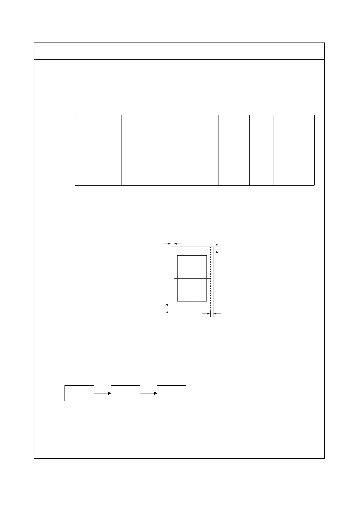
2H9-2
Maintenance
item No.
U402
Description
Adjusting margins of image printing
Description
Adjusts margins for image printing.
Purpose
Make the adjustment if margins are incorrect.
Adjustment
1. Press the start key.
2. Select the item to be adjusted using the cursor up/down keys.
Display Description
Setting
range
Initial
setting
LEAD Printer leading edge margin 0 to 100 30 0.1 mm
A Margin Printer left margin 0 to 100 25 0.1 mm
C Margin Printer right margin 0 to 100 25 0.1 mm
TRAIL Printer trailing edge margin 0 to 100 50 0.1 mm
TRAIL(DUPLEX) Printer trailing edge margin
0 to 100 50 0.1 mm
(second page)
3. Press the system menu/counter key.
4. Press the start key to output a test pattern.
5. Press the system menu/counter key.
6. Change the setting value using the cursor left/right keys or numeric keys.
Increasing the value makes the margin wider, and decreasing it makes the margin narrower.
Change in
value per step
Printer leading edge margin
(3.0±2.5 mm)
Printer
left margin
(2.0+2.0/-1.5 mm)
Printer
Printer trailing edge margin
(3.0±2.5 mm)
right margin
(2.0+2.0/-1.5 mm)
Figure 1-3-14
7. Press the start key. The value is set.
Caution
Check the copy image after the adjustment. If the image is still incorrect, perform the following adjustments in
maintenance mode.
U402
U403
(P.1-3-43)
U404
(P.1-3-44)
1-3-42
Completion
Press the stop key. The screen for selecting a maintenance item No. is displayed.
Page 69

2H9-1
Maintenance
item No.
U403
Description
Adjusting margins for scanning an original on the platen
Description
Adjusts margins for scanning the original on the platen.
Purpose
Make the adjustment if margins are incorrect.
Adjustment
1. Press the start key.
2. Select the item to be adjusted using the cursor up/down keys.
Display Description
Setting
range
Initial
setting
A MARGIN Scanner left margin 0 to 10.0 2.0 0.5 mm
B MARGIN Scanner leading edge margin 0 to 10.0 2.0 0.5 mm
C MARGIN Scanner right margin 0 to 10.0 2.0 0.5 mm
D MARGIN Scanner trailing edge margin 0 to 10.0 5.0 0.5 mm
3. Press the system menu/counter key.
4. Place an original and press the start key to make a test copy.
5. Press the system menu/counter key.
6. Change the setting value using the cursor left/right keys.
Increasing the value makes the margin wider, and decreasing it makes the margin narrower.
Scanner leading edge margin
(3.0±2.5 mm)
Scanner
left margin
(2.5+1.5/-2.0 mm)
Change in
value per step
Scanner
Scanner trailing edge margin
(3.0±2.0 mm)
right margin
(2.5+1.5/-2.0 mm)
Figure 1-3-15
7. Press the start key. The value is set.
Caution
Check the copy image after the adjustment. If the image is still incorrect, perform the following adjustments in
maintenance mode.
U403
U404
(P.1-3-44)
Completion
Press the stop key. The screen for selecting a maintenance item No. is displayed.
1-3-43
Page 70

2H9-1
Maintenance
item No.
U404
Description
Adjusting margins for scanning an original from the DP
Description
Adjusts margins for scanning the original from the DP.
Purpose
Make the adjustment if margins are incorrect when the optional DP is used.
Caution
Before making this adjustment, ensure that the following adjustments have been made in maintenance mode.
U402
(P.1-3-42)
U403
(P.1-3-43)
U404
Adjustment
1. Press the start key.
2. Select the item to be adjusted using the cursor up/down keys.
Display Description
Setting
range
Initial
setting
Change in
value per step
A MARGIN Left margin 0 to 10.0 3.0 0.5 mm
B MARGIN Leading edge margin 0 to 10.0 2.5 0.5 mm
C MARGIN Right margin 0 to 10.0 3.0 0.5 mm
D MARGIN Trailing edge margin 0 to 10.0 4.0 0.5 mm
3. Press the system menu/counter key.
4. Place an original on the DP and press the start key to make a test copy.
5. Press the system menu/counter key.
6. Change the setting value using the cursor left/right keys.
Increasing the value makes the margin wider, and decreasing it makes the margin narrower.
DP leading edge margin
(3.0±1.5 mm)
DP left margin
(2.0±1.0 mm)
DP right margin
DP trailing edge margin
(2.0±1.0 mm)
(2.0±1.0 mm)
Figure 1-3-16
7. Press the start key. The value is set.
Completion
Press the stop key. The screen for selecting a maintenance item No. is displayed.
1-3-44
Page 71

2H9-1
Maintenance
item No.
U407
Description
Adjusting the leading edge registration for memory image printing
Description
Adjusts the leading edge registration during memory copying.
Purpose
Make the following adjustment if there is a regular error between the leading edge of the copy image on the
front face and that on the reverse face during duplex switchback copying.
Caution
Before making this adjustment, ensure that the following adjustments have been made in maintenance mode.
U034
(P.1-3-14)
U404
(P.1-3-44)
U402
(P.1-3-42)
U407
U066
(P.1-3-20)
U403
(P.1-3-43)
U071
(P.1-3-24)
Adjustment
1. Press the start key.
Description
Setting
range
Initial
setting
Change in
value per step
Leading edge registration for memory image printing -47 to 47 0 0.1 mm
2. Press the system menu/counter key.
3. Place an original and press the start key to make a test copy.
4. Press the system menu/counter key.
5. Change the setting value using the cursor left/right keys.
For copy example 1, decrease the value.
For copy example 2, increase the value.
Original Copy
example 1
Copy
example 2
Figure 1-3-17
6. Press the start key. The value is set.
Completion
Press the stop/clear key. The screen for selecting a maintenance item No. is displayed.
1-3-45
Page 72

2H9-1
Maintenance
item No.
U411
Description
Adjusting the scanner automatically
Description
Uses the adjustment original suppled with DP and automatically adjusts the following items in the scanner and
the DP scanning sections.
Purpose
To perform automatic adjustment of various items in the scanner and the DP scanning sections.
Method
1. Press the start key.
Display Description Original to be used
for adjustment (P/N)
ADJUST TABLE Automatic adjustment in the scanner section:
Original size magnification, leading edge timing,
center line, input gamma, input gamma in monochrome mode and matrix
ADJUST DP Automatic adjustment in the DP scanning section:
Original size magnification, leading edge timing,
center line
Method: TABLE
1. Enter the target values which are shown on the specified original (P/N: 302FZ56990) executing maintenance item U425.
2. Set a specified original (P/N: 302FZ56990) on the platen.
3. Enter maintenance item U411.
4. Select [ADJUST TABLE] using the cursor up/down keys.
5. Press the start key. Auto adjustment starts.
When automatic adjustment has normally completed, [OK] is displayed. If a problem occurs during auto
adjustment, [NG XX] (XX is replaced by an error code) is displayed and operation stops. Should this
happen, determine the details of the problem and either repeat the procedure from the beginning, or
adjust the remaining items manually by running the corresponding maintenance items.
6. To return to the screen for selecting an item, press the stop key.
302FZ56990
303LJ57010
(Adjustment original
suppled with DP)
Method: DP
1. Select [ADJUST DP] using the cursor up/down keys.
2. Set a specified original (P/N: 303LJ57010) in the DP.
3. Press the start key. Auto adjustment starts.
When automatic adjustment has normally completed, [OK] is displayed. If a problem occurs during auto
adjustment, [NG XX] (XX is replaced by an error code) is displayed and operation stops. Should this
happen, determine the details of the problem and either repeat the procedure from the beginning, or
adjust the remaining items manually by running the corresponding maintenance items.
4. To return to the screen for selecting an item, press the stop key.
Completion
Press the stop key. The screen for selecting a maintenance item is displayed.
1-3-46
Page 73

2H9-1
Maintenance
item No.
U425
Description
Setting the target
Description
Enters the lab values that is indicated on the back of the chart (P/N: 302FZ56990) used for adjustment.
Purpose
Performs data input in order to correct for differences in originals during automatic adjustment.
Method
1. Press the start key.
2. Select the item to be set using the cursor up/down keys.
Display Description
N875 Setting the N875 patch for the original for adjustment
N475 Setting the N475 patch for the original for adjustment
N125 Setting the N125 patch for the original for adjustment
CYAN Setting the cyan patch for the original for adjustment
MAGENTA Setting the magenta patch for the original for adjustment
YELLOW Setting the yellow patch for the original for adjustment
RED Setting the red patch for the original for adjustment
GREEN Setting the green patch for the original for adjustment
BLUE Setting the blue patch for the original for adjustment
ADJUST ORIGINAL Setting the main and auxiliary scanning directions
3. Select the item to be set using the cursor up/down keys.
Display Description Setting range
L Setting the L value 0.0 to 100.0
a Setting the a value -200.0 to 200.0
b Setting the b value -200.0 to 200.0
4. Enters the value that is indicated on the back of the chart using the cursor left/right keys or numeric
keys.
5. Press the start key. The value is set.
6. To return to the screen for selecting an item, press the stop key.
Setting: [ADJUST ORIGINAL]
1. Measure the distance from the left edge to the black belt (a) of the original at A, B and C.
Measurement procedure
1) Measure the distance from the edge to the black belt (a) of the original at A (30 mm from the leading
edge), B (148.5 mm from the leading edge) and C (267 mm from the leading edge), respectively.
2) Apply the following formula for the values obtained: ((A + C) / 2 + B) / 2
2. Enter the values solved using the cursor left/right keys or numeric keys in [MAIN].
3. Press the start key. The value is set.
4. Measure the distance from the leading edge to the black belt (b) of the original at D, E and F.
Measurement procedure
1) Measure the distance from the edge to the black belt (b) of the original at D (35 mm from the left
edge), E (110 mm from the left edge) and F (185 mm from the left edge), respectively.
2) Apply the following formula for the values obtained: ((D + F) / 2 + E) / 2
5. Enter the values solved using the cursor left/right keys or numeric keys in [SUB LEAD].
6. Press the start key. The value is set.
7. Measure the length (G) from the edge of the black belt (b) to edge of the black belt (c) of the original.
8. Enter the measured value using the cursor left/right keys or numeric keys in [SUB TAIL].
9. Press the start key. The value is set.
10. To return to the screen for selecting an item, press the stop key.
1-3-47
Page 74

2H9-1
Maintenance
item No.
U425
Leading edge
Left edge
35 mm
110 mm
185 mm
Description
30 mm
AC
Black
D
Black
belt (b)
E
F
belt (a)
Original for adjustment (P/N: 302FZ56990)
148.5 mm 267 mm
B
Black
belt (c)
[MAIN] =
((A + C) / 2 + B) / 2
G
[SUB LEAD] =
((D + F) / 2 + E) / 2
[SUB TAIL] = G
U901
Figure 1-3-18
Completion
Press the stop key. The screen for selecting a maintenance item No. is displayed.
Checking copy counts by paper feed locations
Description
Displays or clears copy counts by paper feed locations.
Purpose
To check the time to replace consumable parts.
Method
1. Press the start key. The counts by paper feed locations are displayed.
Display Paper feed locations
MP TRAY MP tray
CASSETTE 1 Cassette 1
CASSETTE 2 Optional cassette 2
CASSETTE 3 Optional cassette 3
DUPLEX Duplex section
When an optional paper feed device is not installed, the corresponding count is not displayed.
Completion
Press the stop key. The screen for selecting a maintenance item No. is displayed.
1-3-48
Page 75

2H9-1
Maintenance
item No.
U903
U904
Description
Checking/clearing the paper jam counts
Description
Displays or clears the jam counts by jam locations.
Purpose
To check the paper jam status. Also to clear the jam counts after replacing consumable parts.
Method
1. Press the start key.
2. Select the item using the cursor up/down keys.
Display Description
COUNT Displays/clears the jam counts
TOTAL COUNT Displays the total jam counts
Method: Displays/clears the jam counts
1. Select [COUNT] and press the start key. The count for jam detection by type is displayed.
2. Change the screen using the cursor up/down keys.
3. To clear the counts for all, select [ALL CLEAR].
4. Press the start key. The count is cleared.
The individual counter cannot be cleared.
5. To return to the screen for selecting an item, press the stop key.
Method: Displays the total jam counts
1. Select [TOTAL COUNT] and press the start key. The total number of jam counts by type is displayed.
2. Change the screen using the cursor up/down keys.
The total number of jam count cannot be cleared.
3. To return to the screen for selecting an item, press the stop key.
Completion
Press the stop key. The screen for selecting a maintenance item No. is displayed.
Checking/clearing the service call counts
Description
Displays or clears the service call code counts by types.
Purpose
To check the service call code status by types. Also to clear the service call code counts after replacing consumable parts.
Method
1. Press the start key.
2. Select the item. The screen for executing is displayed.
Display Description
COUNT Displays/clears the service call counts
TOTAL COUNT Displays the total service call counts
Method: Displays/clears the service call counts
1. Select [COUNT] and press the start key. The count for service call detection by type is displayed.
2. Change the screen using the cursor up/down keys.
3. To clear the counts for all, select [ALL CLEAR].
4. Press the start key. The count is cleared.
The individual counter cannot be cleared.
5. To return to the screen for selecting an item, press the stop key.
Method: Displays the total service call counts
1. Select [TOTAL COUNT] and press the start key. The total number of service call counts by type is displayed.
2. Change the screen using the cursor up/down keys.
The total number of service call count cannot be cleared.
3. To return to the screen for selecting an item, press the stop key.
Completion
Press the stop key. The screen for selecting a maintenance item No. is displayed.
1-3-49
Page 76

2H9-1
Maintenance
item No.
U905
U908
U910
U911
Description
Checking/clearing counts by optional devices
Description
Displays or clears the counts of DP.
Purpose
To check the use of DP. Also to clear the counts after replacing consumable parts.
Method
1. Press the start key.
Display Description
ADP No. of single-sided originals that has passed through the DP
RADP No. of double-sided originals that has passed through the DP
Clearing
1. Select the item to be cleared using the cursor up/down keys.
To clear the counts for all, select [ALL CLEAR].
2. Press the start key. The count is cleared.
Completion
Press the stop key. The screen for selecting a maintenance item No. is displayed.
Checking the total counter value
Description
Displays the total counter value.
Purpose
To check the total counter value.
Method
1. Press the start key. The screen for total count value is displayed.
Completion
Press the stop key. The screen for selecting a maintenance item No. is displayed.
Clearing the black ratio data
Description
Clears the accumulated black ratio data for A4 sheet.
Purpose
To clear data as required at times such as during maintenance service.
Method
1. Press the start key.
2. Select [ALL CLEAR] using the cursor up/down keys.
3. Press the start key. The accumulated black ratio data is cleared.
Completion
Press the stop key. The screen for selecting a maintenance item No. is displayed.
Checking/clearing copy counts by paper sizes
Description
Displays and clears the paper feed counts by paper sizes.
Purpose
To check or clear the counts after replacing consumable parts.
Method
1. Press the start key. The screen for the paper feed counts by paper size is displayed.
Clearing
1. Press the start key.
2. Select the paper size using the cursor up/down keys.
To clear all counts, select [ALL CLEAR].
3. Press the start key. The count is cleared.
Completion
Press the stop/clear key. The screen for selecting a maintenance item No. is displayed.
1-3-50
Page 77

2H9-2
Maintenance
item No.
U917
Description
Setting backup data reading/writing
Description
Retrieves the backup data to a USB memory from the machine; or writes the data from the USB memory to
the machine.
Purpose
To store and write data when replacing the control PWB.
Method
1. Press the power key on the operation panel, and after verifying the power indicator has gone off, switch
off the main power switch.
2. Insert USB memory in USB memory slot.
3. Turn the main power switch on.
Wait for 10 seconds to allow the machine to recognize the USB memory.
4. Enter the maintenance item.
5. Press the start key.
6. Select [Export] or [Import] using the cursor up/down keys and press the start key.
Display Description
IMPORT Writing data from the USB memory to the machine
EXPORT Retrieving from the machine to a USB memory
7. Select the item using the cursor up/down keys.
Display Description Description
ADDRESS BOOK Address book -
JOB ACCNT. Job accounting -
ONE TOUCH Information on one-touch Address book
USER User managements Job accounting
PROGRAM Program information Job accountings and user managements
DOCUMENT BOX Document box information Job accountings and user managements
*: Since data are dependent with each other, data other than those assigned are also retrieved or written
in.
8. Select [ON] using the cursor left/right keys.
9. Press the start key. Starts reading or writing.
The progress of selected item is displayed in %.
When an error occurs, the operation is canceled and an error code is displayed.
10. When normally completed, [FIN] is displayed.
11. Turn the main power switch off and on after completing writing when selecting [IMPORT].
Supplement
The following restrictions apply to the data which were imported from 4in1 models (with FAX) to 3in1 models
(without FAX).
Personal address book: FAX-related data are not imported.
Group address book: Group addresses including FAX addresses are not imported.
Job accounting data: Initial values are added for FAX-related data.
One-touch data: Groups assigned with FAX addresses or those including FAX are not imported.
User management data: Initial values are added for out-going FAXes of authentication.
Program data: Not imported. (The same applies when data are imported from 3in1 to 4in1 models.)
Completion
Press the stop key. The screen for selecting a maintenance item No. is displayed.
1-3-51
Page 78

2H9-1
Maintenance
item No.
U920
U927
U928
U942
Description
Checking the copy counts
Description
Checks the copy counts.
Purpose
To check the copy counts.
Method
Press the start key. The current counts of copy counter and printer counter are displayed.
Completion
Press the stop key. The screen for selecting a maintenance item No. is displayed.
Clearing the all copy counts and machine life counts (one time only)
Description
Resets all of the counts back to 0.
Purpose
To start the counters with value 0 when installing the machine.
Supplement
The total account counter and the machine life counter can be cleared only once if all count values are 1000
or less.
Method
1. Press the start key.
2. Select [EXECUTE].
3. Press the start key. All copy counts and machine life counts are cleared.
Completion
Press the stop key. The screen for selecting a maintenance item No. is displayed.
Checking machine life counts
Description
Displays the machine life counts.
Purpose
To check the machine life counts.
Method
1. Press the start key. The current machine life counts is displayed.
Completion
Press the stop key. The screen for selecting a maintenance item No. is displayed.
Setting of deflection for feeding from DP
Description
Adjusts the deflection generated when the DP is used.
Purpose
Use this mode if an original non-feed jam, oblique feed or wrinkling of original occurs when the DP is used.
Setting
1. Press the start key.
2. Select the item to be adjusted using the cursor up/down keys.
Display Description Setting
range
REGIST TOP Deflection of single-sided original -31 to 31 0 0.098 mm
REGIST
BACK
3. Press the system menu/counter key.
4. Place an original on the DP and press the start key to make a test copy.
5. Press the system menu/counter key.
6. Change the setting value using the cursor left/right keys or numeric keys.
The greater the value, the larger the deflection; the smaller the value, the smaller the deflection.
If an original non-feed jam or oblique feed occurs, increase the setting value. If wrinkling of original
occurs, decrease the value.
7. Press the start key. The setting is set.
Completion
Press the stop key. The screen for selecting a maintenance item No. is displayed.
Deflection of double-sided original -31 to 31 0 0.098 mm
Initial
setting
Change in
value per step
1-3-52
Page 79

2H9-1
Maintenance
item No.
U969
U977
U991
Description
Checking of toner area code
Description
Displays the toner area code.
Purpose
To check the toner area code.
Method
1. Press the start key. The toner area code is displayed.
Completion
Press the stop key. The screen for selecting a maintenance item No. is displayed.
Data capture mode
Description
Store the print data sent to the machine into USB memory.
Purpose
In case to occur the error at printing, check the print data sent to the machine.
Method
1. Insert USB memory in USB memory slot.
2. Turn the main power switch on.
3. Enter the maintenance item.
4. Press the start key.
5. Select [EXECUTE].
6. Press the start key.
7. Send the print data to the machine.
Once the print data is stored into USB memory, OK will be displayed.
Completion
Press the stop key. The screen for selecting a maintenance item No. is displayed.
Checking the scanner count
Description
Displays the scanner operation count.
Purpose
To check the status of use of the scanner.
Method
1. Press the start key.
Display Description
Copy Scn Scanner operation count for copying
Other Scn Scanner operation count except for copying
Completion
Press the stop key. The screen for selecting a maintenance No. item is displayed.
1-3-53
Page 80

2H9-1
Maintenance
item No.
U993
Description
Outputting a VTC-PG pattern
Description
Selects and outputs a VTC-PG pattern created in the machine.
Purpose
When performing respective image printing adjustments, used to check the machine status apart from that of
the scanner with a non-scanned output VTC-PG pattern.
Method
1. Press the start key.
2. Select the VTC-PG pattern to be output using the cursor up/down keys.
Display PG pattern to be output Purpose
PG1 Leading edge registration adjust-
ment
Center line adjustment
Margin adjustment
PG2 Lateral squareness adjustment
Magnification adjustment
3. Press the system menu/counter key.
4. Press the start key. A VTC-PG pattern is output.
5. To return to the screen for selecting an item, press the system menu/counter key.
Completion
Press the stop key. The screen for selecting a maintenance item No. is displayed.
1-3-54
Page 81

2H9-1
1-3-2 Management mode
In addition to a maintenance function for service, the machine is equipped with a management function which can be operated by users (mainly by the administrator). In this management mode, settings such as default settings can be changed.
(1) Using the management mode
Start
Press the System Menu/Counter key.
Select [Common Settings] and
press the OK key.
Press [Copy] and press the OK key. Execute Copy Settings (page 1-3-60).
Press [Send] and press the OK key. Execute Sending Settings (page 1-3-60).
Press [Document Box] and press
the OK key.
Press [Printer] and press the OK key. Execute Printer Settings (page 1-3-61).
Press [Report] and press the OK key. Execute Printing Reports/Sending Notice
Press [Adjust/Maint.] and press the
OK key.
Select [Common Settings] and
press the OK key.
Execute Common Settings (page 1-3-56).
Execute Document Box Settings
(page 1-3-60).
(page 1-3-61.
Execute Adjustment/Maintenance
(page 1-3-62).
Execute Date/Timer (page 1-3-62).
Press [Edit Destination] and press
the OK key.
Press [System] and press the OK key. Execute Restarting the System
Press [User/Job Account] and
press the OK key.
Execute Editing Destination (page 1-3-63).
(page 1-3-64).
Execute Network Setup (page 1-3-64).
Execute User Login Administration
(page 1-3-66).
Execute Job Accounting (page 1-3-66).
End
1-3-55
Page 82

2H9-1
(2) Common Settings
Switching the Language for Display [Language]
1. Select [Language] using the cursor up/down keys.
2. Press the OK key.
3. Select the language you want to use.
4. Press the OK key.
Default Screen
1. Select [Default Screen] using the cursor up/down
keys.
2. Press the OK key.
3. Select the screen to be displayed as the default
screen.
4. Press the OK key.
Sound
1. Select [Sound] using the cursor up/down keys.
2. Press the OK key.
3. Select [Buzzer] using the cursor up/down keys.
4. Press the OK key.
5. Select [Key Confirmation], [Job Finish], [Ready] or
[Warning] using the cursor up/down keys.
6. Select [On] or [Off]
7. Press the OK key.
Display Bright.
1. Select [Display Bright.] using the cursor up/down
keys.
2. Press the OK key.
3. Select the display brightness.
[Darker -3] to [Lighter +3]
4. Press the OK key.
Custom Original Size Setup
1. Select [Orig./Paper Set.] using the cursor up/down
keys.
2. Press the OK key.
3. Select [Custom Orig.Size] using the cursor up/
down keys.
4. Press the OK key.
5. Enter the paper length (Y) using the numeric keys.
6. Press the OK key.
7. Enter the paper width (X) using the numeric keys.
8. Press the OK key.
Default Original Size Setup
1. Select [Orig./Paper Set.] using the cursor up/down
keys.
2. Press the OK key.
3. Select [Def. Orig. Size] using the cursor up/down
keys.
4. Press the OK key.
5. Select the paper size to be used as the default
value.
6. Press the OK key.
Adding a Custom Size and Media Type for Paper to
Print
1. Select [Orig./Paper Set.] using the cursor up/down
keys.
2. Press the OK key.
3. Select [Custom PaperSize] using the cursor up/
down keys.
4. Press the OK key.
5. Select the paper source and press the OK key.
6. Enter the paper length (Y) using the numeric keys.
7. Press the OK key.
8. Enter the paper width (X) using the numeric keys.
9. Press the OK key.
10. Select the media type for which you want to set the
custom size.
11. Press the OK key.
Paper Size and Media Type Setup for Cassettes
1. Select [Orig./Paper Set.] using the cursor up/down
keys.
2. Press the OK key.
3. Select [Cassette 1 ( to 3) Set.] using the cursor up/
down keys.
4. Press the OK key.
5. Select [Cassette 1 ( to 3) Size] using the cursor up/
down keys.
6. Select the paper size.
7. Press the OK key.
8. Select [Cassette 1 ( to 3) Type] using the cursor up/
down keys.
9. Select the paper type.
10. Press the OK key.
Paper Size and Media Type Setup for Multi Purpose
Tray
1. Select [Orig./Paper Set.] using the cursor up/down
keys.
2. Press the OK key.
3. Select [MP Tray Set.] using the cursor up/down
keys.
4. Press the OK key.
5. Select [MP Tray Size] using the cursor up/down
keys.
6. Select the paper size.
If you select [Others], you can select from additional paper sizes.
If you select [Size Entry], you can register a custom
size.
7. Press the OK key.
8. Select [MP Tray Type] and press the OK key.
9. Select the paper type.
10. Press the OK key.
1-3-56
Page 83

2H9-1
Paper Weight
1. Select [Orig./Paper Set.] using the cursor up/down
keys.
2. Press the OK key.
3. Select [MP Tray Set.] using the cursor up/down
keys.
4. Press the OK key.
5. Select the paper type and press the OK key.
6. Select [Paper Weight] and press the OK key.
7. Select the weight of paper.
8. Press the OK key.
9. Select [Print Density] and press the OK key.
10. Select the print density.
11. Press the OK key.
Default Paper Source
1. Select [Orig./Paper Set.] using the cursor up/down
keys.
2. Press the OK key.
3. Select [Def. PaperSource] using the cursor up/
down keys.
4. Press the OK key.
5. Select the paper source to be used preferentially.
6. Press the OK key.
Media for Auto Selection
1. Select [Orig./Paper Set.] using the cursor up/down
keys.
2. Press the OK key.
3. Select [Media for Auto] using the cursor up/down
keys.
4. Press the OK key.
5. Select [All Media Type] or the paper type to be used
for paper selection.
6. Press the OK key.
Special Paper Action
1. Select [Orig./Paper Set.] using the cursor up/down
keys.
2. Press the OK key.
3. Select [SpcialPaper Act.] using the cursor up/down
keys.
4. Press the OK key.
5. Select [Adj. PrintDirect] or [Speed Priority].
6. Press the OK key.
Preset Limit
1. Select [Preset Limit] using the cursor up/down
keys.
2. Press the OK key.
3. Enter the number of copies.
4. Press the OK key.
Switching Unit of Measurement
1. Select [Measurement] using the cursor up/down
keys.
2. Press the OK key.
3. Select [inch] or [mm].
4. Press the OK key.
Error Handling
1. Select [Error Handling] using the cursor up/down
keys.
2. Press the OK key.
3. Select [DuplexPagerError] using the cursor up/
down keys.
4. Press the OK key.
5. Select the method to handle if duplex is disabled.
6. Press the OK key.
7. Select [PagerMismatchErr] using the cursor up/
down keys.
8. Press the OK key.
9. Select the method to handle paper mismatch.
10. Press the OK key.
Orig.Orientation
1. Select [Function Default] using the cursor up/down
keys.
2. Press the OK key.
3. Select [Orig.Orientation] using the cursor up/down
keys.
4. Press the OK key.
5. Select [Top Edge Top] or [Top Edge Left].
6. Press the OK key.
Continuous Scan
1. Select [Function Default] using the cursor up/down
keys.
2. Press the OK key.
3. Select [Continuous Scan] using the cursor up/down
keys.
4. Press the OK key.
5. Select [Off] or [On].
6. Press the OK key.
Original Image
1. Select [Function Default] using the cursor up/down
keys.
2. Press the OK key.
3. Select [Original Image] using the cursor up/down
keys.
4. Press the OK key.
5. Select [Text+Photo], [Photo], [Text] or [for OCR].
6. Press the OK key.
1-3-57
Page 84

2H9-1
Scan Resolution
1. Select [Function Default] using the cursor up/down
keys.
2. Press the OK key.
3. Select [Scan Resolution] using the cursor up/down
keys.
4. Press the OK key.
5. Select the default resolution.
6. Press the OK key.
Color Selection
1. Select [Function Default] using the cursor up/down
keys.
2. Press the OK key.
3. Select [Color Selection] using the cursor up/down
keys.
4. Press the OK key.
5. Select [Full Color], [Grayscale] or [Black & White].
6. Press the OK key.
File Format
1. Select [Function Default] using the cursor up/down
keys.
2. Press the OK key.
3. Select [File Format] using the cursor up/down keys.
4. Press the OK key.
5. Select [PDF], [TIFF], [XPS] or [JPEG].
6. Press the OK key.
Subject/Body
1. Select [Function Default] using the cursor up/down
keys.
2. Press the OK key.
3. Select [Subject/Body] using the cursor up/down
keys.
4. Press the OK key.
5. Enter the e-mail subject (up to 60 characters).
6. Press the OK key.
7. Enter email body text (up to 500 characters).
8. Press the OK key.
Collate
1. Select [Function Default] using the cursor up/down
keys.
2. Press the OK key.
3. Select [Collate] using the cursor up/down keys.
4. Press the OK key.
5. Select [Off] or [On].
6. Press the OK key.
EcoPrint
1. Select [Function Default] using the cursor up/down
keys.
2. Press the OK key.
3. Select [EcoPrint] using the cursor up/down keys.
4. Press the OK key.
5. Select [Off] or [On].
6. Press the OK key.
Density
1. Select [Function Default] using the cursor up/down
keys.
2. Press the OK key.
3. Select [Density] using the cursor up/down keys.
4. Press the OK key.
5. Select [Auto] or [Manual].
6. Press the OK key.
Zoom
1. Select [Function Default] using the cursor up/down
keys.
2. Press the OK key.
3. Select [Zoom] using the cursor up/down keys.
4. Press the OK key.
5. Select [100%] or [Auto].
6. Press the OK key.
File Name Entry
1. Select [Function Default] using the cursor up/down
keys.
2. Press the OK key.
3. Select [File Name Entry] using the cursor up/down
keys.
4. Press the OK key.
5. Select [None], [Date], [JobNo.], [JobNo. + Date] or
[Date + JobNo.].
6. Press the OK key.
2 in 1 Layout
1. Select [Function Default] using the cursor up/down
keys.
2. Press the OK key.
3. Select [Detail Setting] using the cursor up/down
keys.
4. Press the OK key.
5. Select [2 in 1 Layout] using the cursor up/down
keys.
6. Press the OK key.
7. Select [L to R T to B] or [R to L].
8. Press the OK key.
4 in 1 Layout
1. Select [Function Default] using the cursor up/down
keys.
2. Press the OK key.
3. Select [Detail Setting] using the cursor up/down
keys.
4. Press the OK key.
5. Select [4 in 1 Layout] using the cursor up/down
keys.
6. Press the OK key.
7. Select [Right then Down], [Down then Right], [Left
then Down] or [Down then Left].
8. Press the OK key.
1-3-58
Page 85

2H9-1
Border Line
1. Select [Function Default] using the cursor up/down
keys.
2. Press the OK key.
3. Select [Detail Setting] using the cursor up/down
keys.
4. Press the OK key.
5. Select [Border Line] using the cursor up/down keys.
6. Press the OK key.
7. Select [None], [Solid Line], [Dotted Line] or [Positioning Mark].
8. Press the OK key.
Orig. Binding
1. Select [Function Default] using the cursor up/down
keys.
2. Press the OK key.
3. Select [Detail Setting] using the cursor up/down
keys.
4. Press the OK key.
5. Select [Orig. Binding] using the cursor up/down
keys.
6. Press the OK key.
7. Select [Left/Right] or [Top].
8. Press the OK key.
Color TIFF Comp.
1. Select [Function Default] using the cursor up/down
keys.
2. Press the OK key.
3. Select [Detail Setting] using the cursor up/down
keys.
4. Press the OK key.
5. Select [Color TIFF Comp.] using the cursor up/
down keys.
6. Press the OK key.
7. Select [TIFF V6] or [TTN2].
8. Press the OK key.
XPS FitTo Page
1. Select [Function Default] using the cursor up/down
keys.
2. Press the OK key.
3. Select [Detail Setting] using the cursor up/down
keys.
4. Press the OK key.
5. Select [XPS FitTo Page] using the cursor up/down
keys.
6. Press the OK key.
7. Select [On] or [Off].
8. Press the OK key.
Finish Binding
1. Select [Function Default] using the cursor up/down
keys.
2. Press the OK key.
3. Select [Detail Setting] using the cursor up/down
keys.
4. Press the OK key.
5. Select [Finish Binding] using the cursor up/down
keys.
6. Press the OK key.
7. Select [Left/Right] or [Top].
8. Press the OK key.
Image Quality
1. Select [Function Default] using the cursor up/down
keys.
2. Press the OK key.
3. Select [Detail Setting] using the cursor up/down
keys.
4. Press the OK key.
5. Select [Image Quality] using the cursor up/down
keys.
6. Press the OK key.
7. Select the image quality.
[1 Low(High Comp)] to [5 High(Low Comp)]
8. Press the OK key.
Margin Default
1. Press cursor down key, [Next] of Function Defaults,
cursor down key and then [Change] of Margin
Default.
2. Use the [+] or [-] to enter the margin widths for Left/
Right and Top/Bottom(-0.75 - +0.75).
You can use the number keypad to enter the number directly.
3. Press [OK].
Login Operation
1. Select [Login Operation] using the cursor up/down
keys.
2. Press the OK key.
3. Select [Use Numeric Key] or [Select Character].
4. Press the OK key.
1-3-59
Page 86

2H9-1
(3) Copy Settings
Photo Processing
1. Select [Photo Processing] using the cursor up/
down keys.
2. Press the OK key.
3. Select [Dithering(Normal)] or [Dithering(Rough)].
4. Press the OK key.
Paper Selection
1. Select [Paper Selection] using the cursor up/down
keys.
2. Press the OK key.
3. Select [Auto] or [Def. Paper Source].
4. Press the OK key.
Auto Paper Selection
1. Select [AutoPaperSelect.] using the cursor up/down
keys.
2. Press the OK key.
3. Select [MostSuitableSize] or [Same as OrigSize].
4. Press the OK key.
(4) Sending Settings
Select Key Set
1. Select [Select Key Set.] using the cursor up/down
keys.
2. Press the OK key.
3. Select [Left] or [Right].
4. Press the OK key.
5. Select the function you want to register to the flexible key.
6. Press the OK key.
DestinationCheck
1. Select [DestinationCheck] using the cursor up/
down keys.
2. Press the OK key.
3. Select [Dest. Confirm] or [Check New Dest.].
4. Press the OK key.
5. Select [Off] or [On].
6. Press the OK key.
Auto % Priority
1. Select [Auto % Priority.] using the cursor up/down
keys.
2. Press the OK key.
3. Select [Off] or [On].
4. Press the OK key.
Select Key Set
1. Select [Select Key Set.] using the cursor up/down
keys.
2. Press the OK key.
3. Select [Left] or [Right].
4. Press the OK key.
5. select the function you want to register to the flexible key.
6. Press the OK key.
(5) Document Box Settings
Select Key Set
1. Select [Select Key Set.] using the cursor up/down
keys.
2. Press the OK key.
3. Select [Print] or [Store].
4. Press the OK key.
5. Select [Left] or [Right].
6. Press the OK key.
7. Select the function you want to register to the flexible key.
8. Press the OK key.
1-3-60
Page 87

2H9-1
(6) Printer Settings
Emuration Set
1. Select [Emuration Set.] using the cursor up/down
keys.
2. Press the OK key.
3. Select the printer you want to emulate.
4. Press the OK key.
When KPDL Is Selected for Emulation
1. Select [Emuration Set.] using the cursor up/down
keys.
2. Press the OK key.
3. Select [KPDL] and press the OK key.
4. Select [Off] or [On].
5. Press the OK key.
When KPDL(Auto) Is Selected for Emulation
1. Select [Emuration Set.] using the cursor up/down
keys.
2. Press the OK key.
3. Select [KPDL(Auto)] and press the OK key.
4. Select the printer for alternative emulation.
5. Press the OK key.
6. Select [Off] or [On].
7. Press the OK key.
Orientation
1. Select [Orientation] using the cursor up/down keys.
2. Press the OK key.
3. Select [Portrait] or [Landscape].
4. Press the OK key.
FormFeed Timeout
1. Select [FormFeed Timeout] using the cursor up/
down keys.
2. Press the OK key.
3. Set the Form Feed Timeout.
4. Press the OK key.
LF Action
1. Select [LF Action] using the cursor up/down keys.
2. Press the OK key.
3. Select [LF Only], [LF and CR] or [Ignore LF].
4. Press the OK key.
CR Action
1. Select [CR Action] using the cursor up/down keys.
2. Press the OK key.
3. Select [CR Only], [LF and CR] or [Ignore CR].
4. Press the OK key.
EcoPrint
1. Select [EcoPrint] using the cursor up/down keys.
2. Press the OK key.
3. Select [Off] or [On].
4. Press the OK key.
Override A4/LTR
1. Select [Override A4/LTR] using the cursor up/down
keys.
2. Press the OK key.
3. Select [Off] or [On].
4. Press the OK key.
Duplex
1. Select [Duplex] using the cursor up/down keys.
2. Press the OK key.
3. Select [Off], [Bind Long Edge] or [Bind Short Edge].
4. Press the OK key.
Copies
1. Select [Copies] using the cursor up/down keys.
2. Press the OK key.
3. Set the default number of copies.
4. Press the OK key.
Paper Feed Mode
1. Select [Paper Feed Mode] using the cursor up/
down keys.
2. Press the OK key.
3. Select [Auto] or [Fixed].
4. Press the OK key.
(7) Printing Reports/Sending Notice
Printing Reports
1. Select [Report Print] using the cursor up/down
keys.
2. Press the OK key.
3. Select [Menu Map], [Status Page] or [Font List].
4. Press the OK key.
5. Select [Yes].
The selected report is output.
Send Result Report
1. Select [Result Rpt Set.] using the cursor up/down
keys.
2. Press the OK key.
3. Select [Send Result] using the cursor up/down
keys.
4. Press the OK key.
5. Select [E-mail/Folder] using the cursor up/down
keys.
6. Select [Off], [On] or [Error Only].
7. Press the OK key.
1-3-61
Page 88

2H9-1
(8) Adjustment/Maintenance
Copy Denst. Adj.
1. Select [Copy Denst. Adj.] using the cursor up/down
keys.
2. Press the OK key.
3. Select [Auto] or [Manual].
4. Press the OK key.
5. Adjusting the density.
[-3 Lighter] to [+3 Darker]
6. Press the OK key.
Send/Box Density
1. Select [Send/Box Density] using the cursor up/
down keys.
2. Press the OK key.
3. Select [Auto] or [Manual].
4. Press the OK key.
5. Adjusting the density.
[-3 Lighter] to [+3 Darker]
6. Press the OK key.
Correct. Bk Line
1. Select [Correct. Bk Line] using the cursor up/down
keys.
2. Press the OK key.
3. Select [Off], [On(Low)] or [On(High)].
4. Press the OK key.
New Developer
1. Select [Service Setting] using the cursor up/down
keys.
2. Press the OK key.
3. Select [New Developer] using the cursor up/down
keys.
4. Press the OK key.
5. Select [Yes].
(9) Date/Timer
Date/Time
1. Select [Date Setting] using the cursor up/down
keys.
2. Press the OK key.
3. Select [Date/Time] using the cursor up/down keys.
4. Press the OK key.
5. Set the date and press the OK key.
6. Set the time and press the OK key.
Date Format
1. Select [Date Setting] using the cursor up/down
keys.
2. Press the OK key.
3. Select [Date Format] using the cursor up/down
keys.
4. Press the OK key.
5. Select [Month/Day/Year], [Day/Month/Year] or
[Year/Month/Day].
6. Press the OK key.
Time Zone
1. Select [Date Setting] using the cursor up/down
keys.
2. Press the OK key.
3. Select [Time Zone] using the cursor up/down keys.
4. Press the OK key.
5. Select your location.
6. Press the OK key.
Summer Time
1. Select [Date Setting] using the cursor up/down
keys.
2. Press the OK key.
3. Select [Summer Time] using the cursor up/down
keys.
4. Press the OK key.
5. Select [Off] or [On].
6. Press the OK key.
1-3-62
Auto Error Clear ON/OFF
1. Select [Timer Setting] using the cursor up/down
keys.
2. Press the OK key.
3. Select [Auto Err. Clear] using the cursor up/down
keys.
4. Press the OK key.
5. Select [Off] or [On].
6. Press the OK key.
Page 89

2H9-1
Error Clear Timer
1. Select [Timer Setting] using the cursor up/down
keys.
2. Press the OK key.
3. Select [Err. Clear Timer] using the cursor up/down
keys.
4. Press the OK key.
5. Set the Error Clear Timer.
6. Press the OK key.
Auto Sleep
1. Select [Timer Setting] using the cursor up/down
keys.
2. Press the OK key.
3. Select [Auto Sleep] using the cursor up/down keys.
4. Press the OK key.
5. Select [Off] or [On].
6. Press the OK key.
Sleep Timer
1. Select [Timer Setting] using the cursor up/down
keys.
2. Press the OK key.
3. Select [Sleep Timer] using the cursor up/down
keys.
4. Press the OK key.
5. Set the Sleep Timer.
6. Press the OK key.
Unusable Time
1. Select [Timer Setting] using the cursor up/down
keys.
2. Press the OK key.
3. Select [Unusable Time] using the cursor up/down
keys.
4. Press the OK key.
5. Select [On] and press the OK key.
6. Set the Start Time and press the OK key.
7. Set the End Time and press the OK key.
8. Set the unlock code and press the OK key.
(10) Editing Destination (Address Book/Adding One-
Touch Keys)
Adding an Individual Destination
1. Select [Address Book] using the cursor up/down
keys.
2. Press the OK key.
3. Select [Menu].
4. Select [Add Address] using the cursor up/down
keys.
5. Press the OK key.
6. Select [Contact] and press the OK key.
7. Enter each item and press the OK key.
Auto Panel Reset ON/OFF
1. Select [Timer Setting] using the cursor up/down
keys.
2. Press the OK key.
3. Select [Auto Panel Reset] using the cursor up/down
keys.
4. Press the OK key.
5. Select [Off] or [On].
6. Press the OK key.
Panel Reset Timer
1. Select [Timer Setting] using the cursor up/down
keys.
2. Press the OK key.
3. Select [Panel Reset Timer] using the cursor up/
down keys.
4. Press the OK key.
5. Set the Panel Reset Timer.
6. Press the OK key.
Low Power Timer
1. Select [Timer Setting] using the cursor up/down
keys.
2. Press the OK key.
3. Select [Low Power Timer] using the cursor up/down
keys.
4. Press the OK key.
5. Set the Low Power Timer.
6. Press the OK key.
Adding a Group
1. Select [Address Book] using the cursor up/down
keys.
2. Press the OK key.
3. Select [Menu].
4. Select [Add Address] using the cursor up/down
keys.
5. Press the OK key.
6. Select [Group] and press the OK key.
7. Enter each item and press the OK key.
Editing a Destination
1. Select [Address Book] using the cursor up/down
keys.
2. Press the OK key.
3. Select the destination you want to edit.
4. Select [Menu].
5. Select [Detail/Edit] using the cursor up/down keys.
6. Press the OK key.
7. Edit items as necessary.
8. Select [Yes].
1-3-63
Page 90

2H9-1
(11) Restarting the System
Restarting the System
1. Select [Restart] using the cursor up/down keys.
2. Press the OK key.
3. Select [Yes].
The machine is restarted.
(12) Network Setup
LAN Interface Setup
1. Select [Network Setting] using the cursor up/down
keys.
2. Press the OK key.
3. Select [LAN Interface] using the cursor up/down
keys.
4. Press the OK key.
5. Select the desired LAN interface.
6. Press the OK key.
TCP/IP (IPv4) Setup
1. Select [Network Setting] using the cursor up/down
keys.
2. Press the OK key.
3. Select [TCP/IP Settings] using the cursor up/down
keys.
4. Press the OK key.
5. Select [TCP/IP] using the cursor up/down keys.
6. Press the OK key.
7. Select [On] and press the OK key.
8. Select [IPv4 Setting] using the cursor up/down
keys.
9. Press the OK key.
10. Select [DHCP] using the cursor up/down keys.
11. Press the OK key.
12. Select [Off] and press the OK key.
13. Select [Bonjour] using the cursor up/down keys.
14. Press the OK key.
15. Select [Off] and press the OK key.
16. Select [IP Address] using the cursor up/down keys.
17. Press the OK key.
18. Enter the IP address and press the OK key.
19. Select [Subnet Mask] using the cursor up/down
keys.
20. Press the OK key.
21. Enter the Subnet Mask and press the OK key.
22. Select [Default Gateway] using the cursor up/down
keys.
23. Press the OK key.
24. Enter the Default Gateway and press the OK key.
TCP/IP (IPv6) Setup
1. Select [Network Setting] using the cursor up/down
keys.
2. Press the OK key.
3. Select [TCP/IP Settings] using the cursor up/down
keys.
4. Press the OK key.
5. Select [IPv6 Setting] using the cursor up/down
keys.
6. Press the OK key.
7. Select [On] or [Off].
8. Press the OK key.
NetWare Setup
1. Select [Network Setting] using the cursor up/down
keys.
2. Press the OK key.
3. Select [NetWare] using the cursor up/down keys.
4. Press the OK key.
5. Select [On] or [Off].
6. Press the OK key.
7. Select the desired frame type.
8. Press the OK key.
AppleTalk Setup
1. Select [Network Setting] using the cursor up/down
keys.
2. Press the OK key.
3. Select [AppleTalk] using the cursor up/down keys.
4. Press the OK key.
5. Select [On] or [Off].
6. Press the OK key.
WSD Scan Setup
1. Select [Network Setting] using the cursor up/down
keys.
2. Press the OK key.
3. Select [WSD-SCAN] using the cursor up/down
keys.
4. Press the OK key.
5. Select [On] or [Off].
6. Press the OK key.
WSD Print Setup
1. Select [Network Setting] using the cursor up/down
keys.
2. Press the OK key.
3. Select [WSD-PRINT] using the cursor up/down
keys.
4. Press the OK key.
5. Select [On] or [Off].
6. Press the OK key.
1-3-64
Page 91

2H9-1
Protocol Detail
1. Select [Network Setting] using the cursor up/down
keys.
2. Press the OK key.
3. Select [TCP/IP Settings] using the cursor up/down
keys.
4. Press the OK key.
5. Select [Protocol Detail] using the cursor up/down
keys.
6. Press the OK key.
7. Select the item for which you want to make settings.
8. Select [On] or [Off].
9. Press the OK key.
Network Security
SSL Setting
1. Select [Network Setting] using the cursor up/down
keys.
2. Press the OK key.
3. Select [Secure Protocol] using the cursor up/down
keys.
4. Press the OK key.
5. Select [SSL] using the cursor up/down keys.
6. Press the OK key.
7. Select [On] or [Off].
8. Press the OK key.
IPP Security
1. Select [Network Setting] using the cursor up/down
keys.
2. Press the OK key.
3. Select [Secure Protocol] using the cursor up/down
keys.
4. Press the OK key.
5. Select [IPP Security] using the cursor up/down
keys.
6. Press the OK key.
7. Select [IPP/IPP over SSL] or [IPPoverSSL only].
8. Press the OK key.
HTTP Security
1. Select [Network Setting] using the cursor up/down
keys.
2. Press the OK key.
3. Select [Secure Protocol] using the cursor up/down
keys.
4. Press the OK key.
5. Select [HTTP Security] using the cursor up/down
keys.
6. Press the OK key.
7. Select [HTTP/HTTPS] or [HTTPS only].
8. Press the OK key.
LDAP Security
1. Select [Network Setting] using the cursor up/down
keys.
2. Press the OK key.
3. Select [Secure Protocol] using the cursor up/down
keys.
4. Press the OK key.
5. Select [LDAP Security] using the cursor up/down
keys.
6. Press the OK key.
7. Select [Off], [LDAPv3/TLS] or [LDAP over SSL].
8. Press the OK key.
LDAP Security
1. Select [Network Setting] using the cursor up/down
keys.
2. Press the OK key.
3. Select [IPSec] using the cursor up/down keys.
4. Press the OK key.
5. Select [On] or [Off].
6. Press the OK key.
Interface Block Setting
USB Host (USB memory slot setting)
1. Select [I/F Block Set.] using the cursor up/down
keys.
2. Press the OK key.
3. Select [USB Host] using the cursor up/down keys.
4. Press the OK key.
5. Select [Unblock] or [Block].
6. Press the OK key.
USB Device (USB interface setting)
1. Select [I/F Block Set.] using the cursor up/down
keys.
2. Press the OK key.
3. Select [USB Device] using the cursor up/down
keys.
4. Press the OK key.
5. Select [Unblock] or [Block].
6. Press the OK key.
Optional interface (Optional interface card setting)
1. Select [I/F Block Set.] using the cursor up/down
keys.
2. Press the OK key.
3. Select [Option I/F] using the cursor up/down keys.
4. Press the OK key.
5. Select [Unblock] or [Block].
6. Press the OK key.
1-3-65
Page 92

2H9-1
(13) User Login Administration
Enabling/Disabling User Login Administration
1. Select [User Login Set.] using the cursor up/down
keys.
2. Press the OK key.
3. Select [User Login] using the cursor up/down keys.
4. Press the OK key.
5. Select [Local Authentic.] or [Netwk Authentic.].
Select [Off] to disable user login administration.
If you select [Netwk Authentic.], enter the host
name (64 characters or less) and domain name
(256 characters or less) for the Authentication
Server. Select [NTLM] or [Kerberos] as the server
type.
6. Press the OK key.
Adding a User
1. Select [User Login Set.] using the cursor up/down
keys.
2. Press the OK key.
3. Select [Local User List] using the cursor up/down
keys.
4. Press the OK key.
5. Select [Menu].
6. Select [Add User] and press the OK key.
7. Enter the user name and press the OK key.
8. Enter the login user name and press the OK key.
9. Select [Exit] and press the OK key.
10. Select the added user and press the OK key.
11. Select [Login Password:].
12. Select [Edit] and enter the login password.
13. Press the OK key.
14. Enter the same login password to confirm and
press the OK key.
15. Select [E-mailAddress:].
16. Select [Edit] and enter the e-mail address.
17. Press the OK key.
18. Select [Access Level:]
19. Select [Change] and select the user access privilege.
20. Press the OK key.
21. Select [Account Name:].
22. Select [Change] and select the account.
23. Press the OK key.
24. Press the OK key.
Changing User Properties
1. Select [User Login Set.] using the cursor up/down
keys.
2. Press the OK key.
3. Select [Local User List] using the cursor up/down
keys.
4. Press the OK key.
5. Select the user whose information you want to
change.
The procedure differs depending on the details to
be edited.
Changing user information
1. Select [Edit].
2. In the same fashion as registering a new user,
change information.
3. Press the OK key.
4. Select [Yes]. The user information is changed.
Deleting a user
1. Select [Menu].
2. Select [Delete] and press the OK key.
3. Select [Yes]. The selected user will be deleted.
Unknown login user name Job
1. Select [User Login Set.] using the cursor up/down
keys.
2. Press the OK key.
3. Select [Unknown ID Job] using the cursor up/down
keys.
4. Press the OK key.
5. Select [Reject] or [Permit].
6. Press the OK key.
(14) Job accounting
Enabling/Disabling Job Accounting
1. Select [Job Account. Set.] using the cursor up/down
keys.
2. Press the OK key.
3. Select [Job Accountin] using the cursor up/down
keys.
4. Press the OK key.
5. Select [On] or [Off].
6. Press the OK key.
1-3-66
Adding an Account
1. Select [Job Account. Set.] using the cursor up/down
keys.
2. Press the OK key.
3. Select [Account. List] using the cursor up/down
keys.
4. Press the OK key.
5. Select [Menu].
6. Select [Add Account], and press the OK key.
7. Enter the account name and press the OK key.
8. Enter the account code and press the OK key.
9. Select [Exit] and press the OK key.
Page 93

2H9-1
Managing Accounts
1. Select [Job Account. Set.] using the cursor up/down
keys.
2. Press the OK key.
3. Select [Account. List] using the cursor up/down
keys.
4. Press the OK key.
5. Select an account to change or delete.
Changing account information
1. Select [Edit].
2. Change account information and restriction of
use.
3. Press the OK key.
4. Select [Yes]. The account information is
changed.
Deleting an account
1. Select [Menu].
2. Select [Delete] and press the OK key.
3. Select [Yes]. The account is deleted.
Managing the Copier/Printer Counts
1. Select [Job Account. Set.] using the cursor up/down
keys.
2. Press the OK key.
3. Select [Default Setting] using the cursor up/down
keys.
4. Press the OK key.
5. Select [Copy/Print Count] using the cursor up/down
keys.
6. Press the OK key.
7. Select [Total] or [Split].
8. Press the OK key.
Default Counter Limit
1. Select [Job Account. Set.] using the cursor up/down
keys.
2. Press the OK key.
3. Select [Default Setting] using the cursor up/down
keys.
4. Press the OK key.
5. Select [Counter Limit] using the cursor up/down
keys.
6. Press the OK key.
7. Select the item for which you want to set the default
restriction on the number of sheets and press the
OK key.
8. Enter the default restriction on the number of
sheets and press the OK key.
9. Repeat steps 7 to 8 set other default restrictions on
the number of sheets.
Total Job Accounting/Resetting the Counter
1. Select [Job Account. Set.] using the cursor up/down
keys.
2. Press the OK key.
3. Select [Total Accounting] using the cursor up/down
keys.
4. Press the OK key.
5. Select the function of which you want to check
counts and press the OK key.
6. After confirming the content press the OK key.
7. To reset the counter, select [Counter Reset].
8. Press the OK key.
9. Select [Yes].
Applying Restriction
1. Select [Job Account. Set.] using the cursor up/down
keys.
2. Press the OK key.
3. Select [Account. List] using the cursor up/down
keys.
4. Press the OK key.
5. Select the account to which you want to set restriction of use and press the OK key.
6. Select the item to be restricted and select [Edit].
7. Select the desired restriction method and press the
OK key.
8. Repeat step 6 to 7 to set items as necessary.
9. Press the OK key.
10. Select [Yes].
Applying Limit of Restriction
1. Select [Job Account. Set.] using the cursor up/down
keys.
2. Press the OK key.
3. Select [Default Setting] using the cursor up/down
keys.
4. Press the OK key.
5. Select [Apply Limit] using the cursor up/down keys.
6. Press the OK key.
7. Select [Immediately], [Subsequently] or [Alert Only].
8. Press the OK key.
Each Job Accounting/Resetting the Counter
1. Select [Job Account. Set.] using the cursor up/down
keys.
2. Press the OK key.
3. Select [Each Job Account] using the cursor up/
down keys.
4. Press the OK key.
5. Select the account of which you want to check
counts and press the OK key.
6. Select the function of which you want to check
counts and press the OK key.
7. After confirming the content press the OK key.
8. To reset the counter, select [Counter Reset].
9. Press the OK key.
10. Select [Yes].
Printing an Accounting Report
1. Select [Job Account. Set.] using the cursor up/down
keys.
2. Press the OK key.
3. Select [Account. Report] using the cursor up/down
keys.
4. Press the OK key.
5. Select [Yes]. A job accounting report is printed.
1-3-67
Page 94

2H9
This page is intentionally left blank.
1-3-68
Page 95

1-4 Troubleshooting
r
1-4-1 Paper misfeed detection
(1) Paper misfeed indication
When a paper misfeed occurs, the printer immediately stops printing and displays the paper misfeed message on the
operation panel. To remove paper misfed in the printer, pull out the paper cassette, open the front cover, rear cover or
duplexer’s cover, or remove the drum unit.
Paper
jammed in
the printer
JAM**
Help
Figure 1-4-1Paper misfeed indication
(2) Paper misfeed detection condition
2H9
Registration sensor
Paper sensor
MP paper sensor
Exit sensor
PF paper feed senso
PF paper sensor
Printer
Peper feeder 1
(Option)
Peper feeder 2
(Option)
Figure 1-4-2
1-4-1
Page 96

2H9
1-4-2 Self-diagnostic function
(1) Self-diagnostic function
This printer is equipped with self-diagnostic function. When a problem is detected, the printer stops printing and display an
error message on the operation panel. An error message consists of a message prompting a contact to service personnel,
total print count, and a four-digit error code indicating the type of the error. (The display varies depending on the type of
the error.)
Machine failure.
Call service.
C####
Figure 1-4-3
1-4-2
Page 97

(2) Self diagnostic codes
2H9-1
Code Contents
Causes Check procedures/corrective measures
0100 Backup memory device error Defective flash
memory.
Defective control
PWB.
0120 MAC address data error Defective flash
memory.
0130 Backup memory read/write error Defective flash
memory.
Defective control
PWB.
0140 Backup memory data error Defective flash
memory.
Defective control
PWB.
0150 Control PWB EEPROM error
Detecting control PWB EEPROM (U17)
communication error.
Improper installation control PWB
EEPROM (U17).
Defective control
PWB.
Remarks
Replace the control PWB (See page 1-5-
39).
Replace the control PWB (See page 1-5-
39).
Replace the control PWB (See page 1-5-
39).
Replace the control PWB (See page 1-5-
39).
Replace the control PWB (See page 1-5-
39).
Replace the control PWB (See page 1-5-
39).
Replace the control PWB (See page 1-5-
39).
Check the installation of the EEPROM (U17)
and remedy if necessary (See page 1-5-39).
Replace the control PWB (See page 1-5-
39).
Data damage of
control PWB
EEPROM (U17).
0170 Billing counting error Defective control
PWB.
Data damage of
control PWB
EEPROM (U17).
0180 Machine number mismatch
Machine number of main and engine
does not match.
Data damage of
control PWB
EEPROM (U17).
Contact the Service Administrative Division.
Replace the control PWB (See page 1-5-
39).
Contact the Service Administrative Division.
Contact the Service Administrative Division.
1-4-3
Page 98

2H9
Code Contents
0420 Paper feeder communication error
Communication error between control
PWB and optional paper feeder.
2000 Main motor error
The main motor ready input is not given
for 2 s during the main motor is ON.
Remarks
Causes Check procedures/corrective measures
Improper installation paper feeder.
Defective harness
between control
PWB (YC30) and
paper feeder interface connector, or
improper connector insertion.
Defective control
PWB.
Defective harness
between PF main
PWB (YC5) and
paper feeder interface connector, or
improper connector insertion.
Defective PF mainPWB.
Defective harness
between main
motor (CN1) and
control PWB
(YC17), or
improper connector insertion.
Defective drive
transmission system of the main
motor.
Follow installation instruction carefully again.
Reinsert the connector. Also check for continuity within the connector harness. If none,
remedy or replace the harness.
Replace the control PWB (See page 1-5-
39).
Reinsert the connector. Also check for continuity within the connector harness. If none,
remedy or replace the harness (Refer to the
service manual for the paper feeder).
Replace the PF main PWB (Refer to the service manual for the paper feeder).
Reinsert the connector. Also check for continuity within the connector harness. If none,
remedy or replace the harness (See page 15-50).
Check if the rollers and gears rotate
smoothly. If not, grease the bushings and
gears. Check for broken gears and replace if
any.
2610 PF paper feed motor error
(Optional paper feeder 1)
The PF paper feed motor of paper
feeder 1 ready input is not given for 2 s
during the PF paper feed motor is ON.
Defective main
motor.
Defective control
PWB.
Defective harness
between PF paper
feed motor and PF
main PWB (YC4),
or improper connector insertion.
Defective PF paper
feed motor drive
transmission
system.
Defective PF main
motor.
Defective control
PWB.
Replace the main motor (See page 1-5-50).
Replace the control PWB (See page 1-5-
39).
Reinsert the connector. Also check for continuity within the connector harness. If none,
remedy or replace the harness (Refer to the
service manual for the paper feeder).
Check if the gears rotate smoothly. If not,
grease the bushings and gears. Check for
broken gears and replace if any.
Replace the PF main motor.
Replace the control PWB (See page 1-5-
39).
1-4-4
Page 99

2H9-1
Code Contents
Causes Check procedures/corrective measures
2620 PF paper feed motor error
(Optional paper feeder 2)
The PF paper feed motor of paper
feeder 2 ready input is not given for 2 s
during the PF paper feed motor is ON.
3100 ISU home position error Defective FFC
Defective harness
between PF paper
feed motor and PF
main PWB (YC4),
or improper connector insertion.
Defective PF paper
feed motor drive
transmission system.
Defective PF main
motor.
Defective control
PWB.
between CCD
PWB (YC1) and
control PWB
(YC8).
Defective FFC
between control
PWB (YC6) and
scanner PWB
(YC103), or
improper FFC
insertion.
Defective home
position sensor.
Remarks
Reinsert the connector. Also check for continuity within the connector harness. If none,
remedy or replace the harness (Refer to the
service manual for the paper feeder).
Check if the gears rotate smoothly. If not,
grease the bushings and gears. Check for
broken gears and replace if any.
Replace the PF main motor (Refer to the
service manual for the paper feeder).
Replace the control PWB (See page 1-5-
39).
Replace the image scanner unit (ISU) (See
page 1-5-21).
Reinsert the FFC. Also check for continuity
within the FFC. If none, remedy or replace
the FFC.
Replace the home position sensor.
Defective harness
between ISU motor
and scanner PWB
(YC104), or
improper connector insertion.
Defective ISU
motor.
Reinsert the connector. Also check for continuity within the connector harness. If none,
remedy or replace the harness.
Replace the ISU motor.
1-4-5
Page 100

2H9-1
Code Contents
3200 Exposure lamp error
The exposure lamp is not turned on.
Remarks
Causes Check procedures/corrective measures
Defective FFC
between scanner
PWB (YC103) and
control PWB
(YC6), or improper
FFC insertion.
Defective FFC
between CCD
PWB (YC1) and
control PWB
(YC8).
Defective harness
between CCD
PWB (YC3) and
inverter PWB
(YC101), or
improper connector insertion.
Defective harness
between inverter
PWB (YC102) and
exposure lamp, or
improper connector insertion.
Defective exposure
lamp.
Defective inverter
PWB.
Reinsert the FFC. Also check for continuity
within the FFC. If none, remedy or replace
the FFC.
Replace the image scanner unit (ISU) (See
page 1-5-21).
Reinsert the connector. Also check for continuity within the connector harness. If none,
remedy or replace the harness.
Reinsert the connector. Also check for continuity within the connector harness. If none,
remedy or replace the harness.
Replace the exposure lamp (See page 1-5-
27).
Replace the inverter PWB (See page 1-5-
27).
3300 AGC error
After AGC, correct input is not obtained
at CCD.
Defective control
PWB.
Defective FFC
between CCD
PWB (YC1) and
control PWB
(YC8).
Defective exposure
lamp.
Defective CCD
PWB.
Defective control
PWB.
Replace the control PWB (See page 1-5-
39).
Replace the image scanner unit (ISU) (See
page 1-5-21).
Replace the exposure lamp (See page 1-5-
27).
Replace the CCD PWB.
Replace the control PWB (See page 1-5-
39).
1-4-6
 Loading...