

Kyocera FS-1000 PLUS User Manual
Page Printer
Installation Manual
Ifs10ep-jp.book Page 1 Friday, December 22, 2000 4:27 PM
Caution
NO LIABILITY IS ASSUMED FOR ANY DAMAGE CAUSED BY IMPROPER INSTALLATION.
Notice on Software
SOFTWARE USED WITH THIS PRINTER MUST SUPPORT THE PRINTER'S EMULATION
MODE. The printer is factory-set to emulate the HP PCL 6. The emulation mode can be changed by
following the procedures described in the User's Manual contained as an electronic file in the
Kyocera Mita Digital Library CD-ROM supplied with the printer.
Notice
The information in this manual is subject to change without notification. Additional pages may be
inserted in future editions. The user is asked to excuse any technical inaccuracies or typographical
errors in the present edition.
No responsibility is assumed if accidents occur while the user is following the instructions in this
manual. No responsibility is assumed for defects in the printer's firmware (contents of its read-only
memory).
This manual, any copyrightable subject matter sold or provided with or in connection with the sale
of the page printer, are protected by copyright. All rights are reserved. Copying or other reproduction of all or part of this manual, any copyrightable subject matter without the prior written consent
of Kyocera Corporation is prohibited. Any copies made of all or part of this manual, any copyrightable subject must contain the same copyright notice as the material from which the copying is done.
Table of Contents
STEP1 Unpacking.........................................................................1
STEP2 Positioning the Printer .....................................................2
STEP3 Installing the Toner Container .........................................3
STEP4 Connecting the Printer to the Computer.........................6
STEP5 Connecting the Power Cord ............................................8
STEP6 Adding Paper to the Paper Cassette and MP Tray .........9
STEP7 Using the Face-Up Output Tray .....................................14
STEP8 Printing a Status Page....................................................15
©2000 by Kyocera Corporation. All rights reserved, Revision 1.0., December 2000
Ifs10ep-jp.book Page 1 Friday, December 22, 2000 4:27 PM
STEP
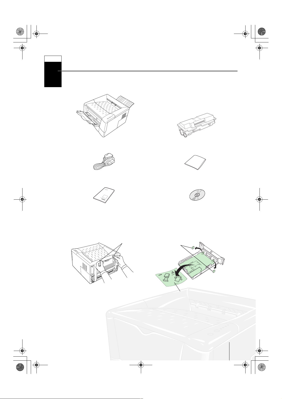
Unpacking
Carefully remove the printer and other items from the box. Check that nothing is miss-
1
ing against the list of shipped components below.
Shipped Components
Printer
Power Cord
Installation Manual (this booklet) Kyocera Mita Digital Library CD-ROM
Toner Container (TK-17)
Cleaning Cloth
Removing Shipping Material
Remove the tape on the rear side of the printer, and remove the two spacers and
printed notice from the paper cassette.
Ta p e
Spacers
Printed Notice
Go to nex t pa ge
☞
1
Ifs10ep-jp.book Page 2 Friday, December 22, 2000 4:27 PM
STEP
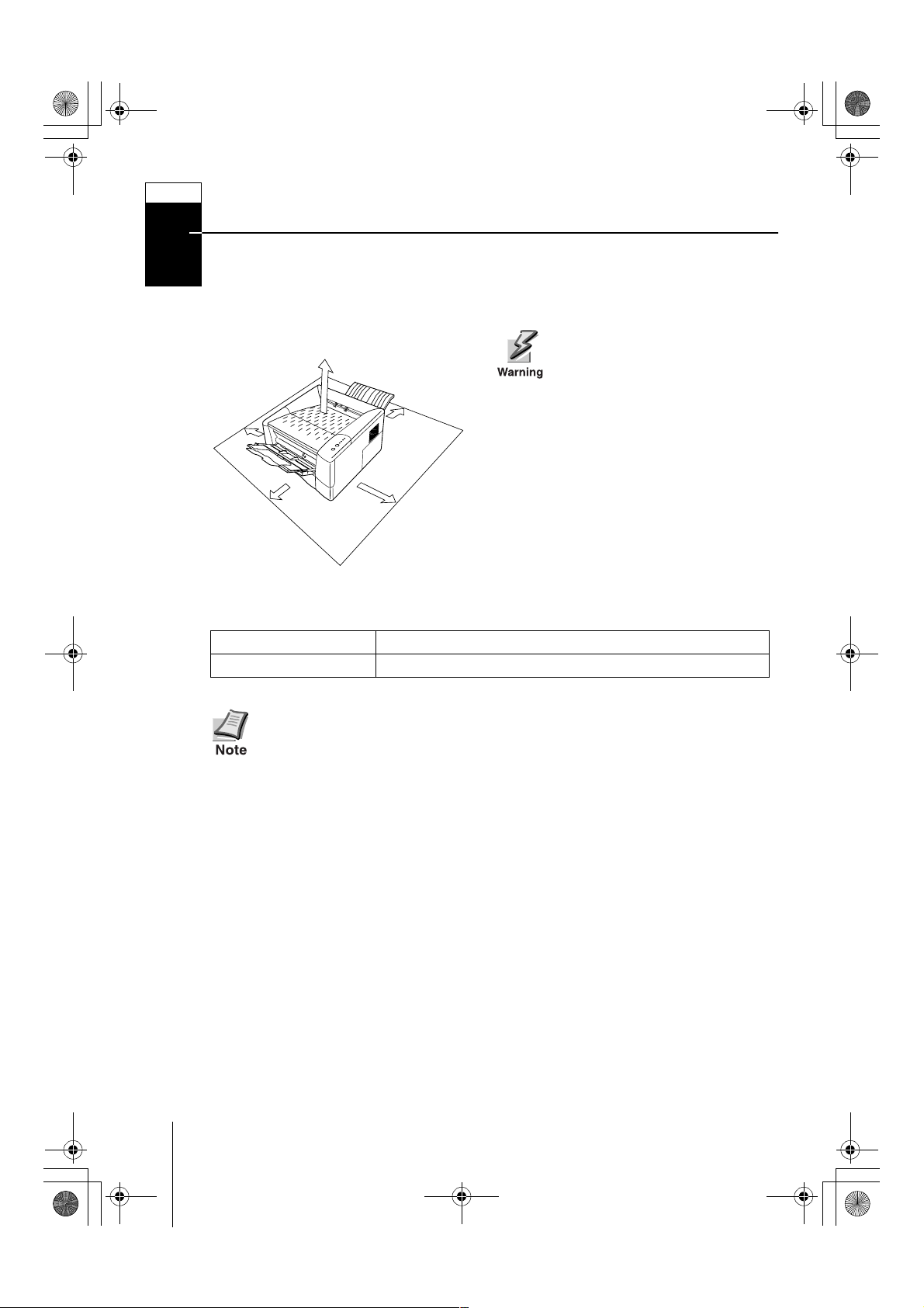
Positioning the Printer
Make sure that the place of installation meets the following requirements:
2
Clearance
Be sure to secure enough space
around the printer. Prolonged
use without sufficient clearance
may cause heat to build up
within the printer, resulting in
fire.
25 cm (9-7/8
inches)
50 cm
(19-11/16
inches)
30 cm (11-13/16 inches)
40 cm
(15-3/4
inches)
25 cm
(9-7/8
inches)
Environment
Temperature
Humidity
Do not install the printer where temperature or humidity is outside the recommended range. Print quality may suffer and there will be an increased
chance of paper jams.
10 to 32.5 °C (50 to 90.5 °F), ideally about 23 °C (73.4 °F)
20 to 80 %, ideally 60 %
Places to Avoid
Avoid installing the printer in locations subject to:
• Direct drafts of hot or cold air
• Direct drafts from outside (Avoid locations near building entrances.)
• Sudden temperature or humidity changes
• Sources of high temperature, for example, near stoves or radiators
•Excessive dust
•Vibration
• Unstable surfaces and surfaces that are not level
• Ammonia or other harmful fumes (If you are planning to fumigate the room, or
make liberal use of insecticide, remove the printer first!)
• Excessive sunlight or humidity
• Lack of ventilation
• Low air pressure, e.g., elevations greate r than 2000 mete rs (6500 feet) above sea
level
2
Ifs10ep-jp.book Page 3 Friday, December 22, 2000 4:27 PM
STEP
Installing the Toner Container
Before you can us e the printer for the first time, you must set up the print er by installing
3
the toner container and interfacing with the computer.
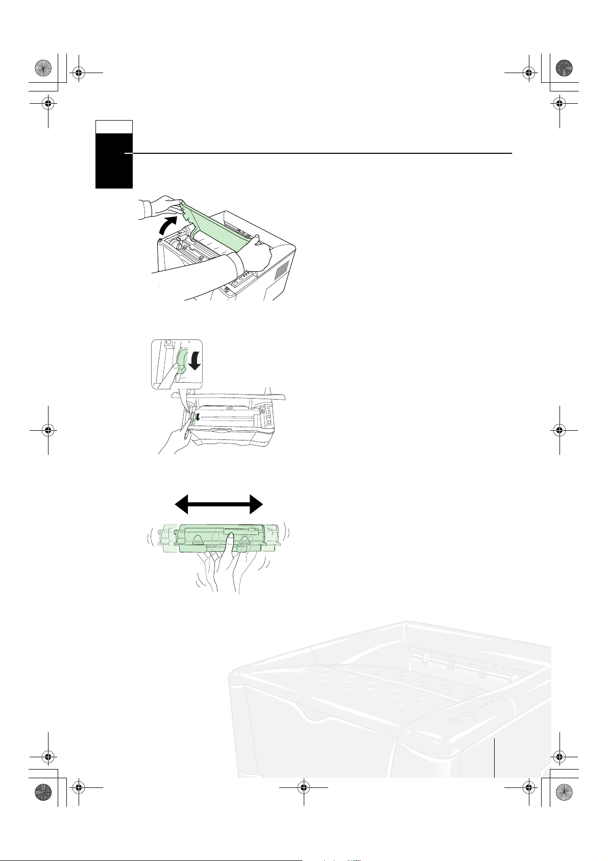
1
Open the printer top cover all the way.
2
Confirm that the lock lever is in the
release (UNLOCK) position. If not, pull it
forward until it is in the release position.
3
Take the toner container from the bag.
Hold it with the protective seal (orangecolored) facing up. Shake the toner container horizontally a t least 5 times. This
ensures that the toner is evenly distributed inside.
Go to nex t pa ge
☞
3
Ifs10ep-jp.book Page 4 Friday, December 22, 2000 4:27 PM
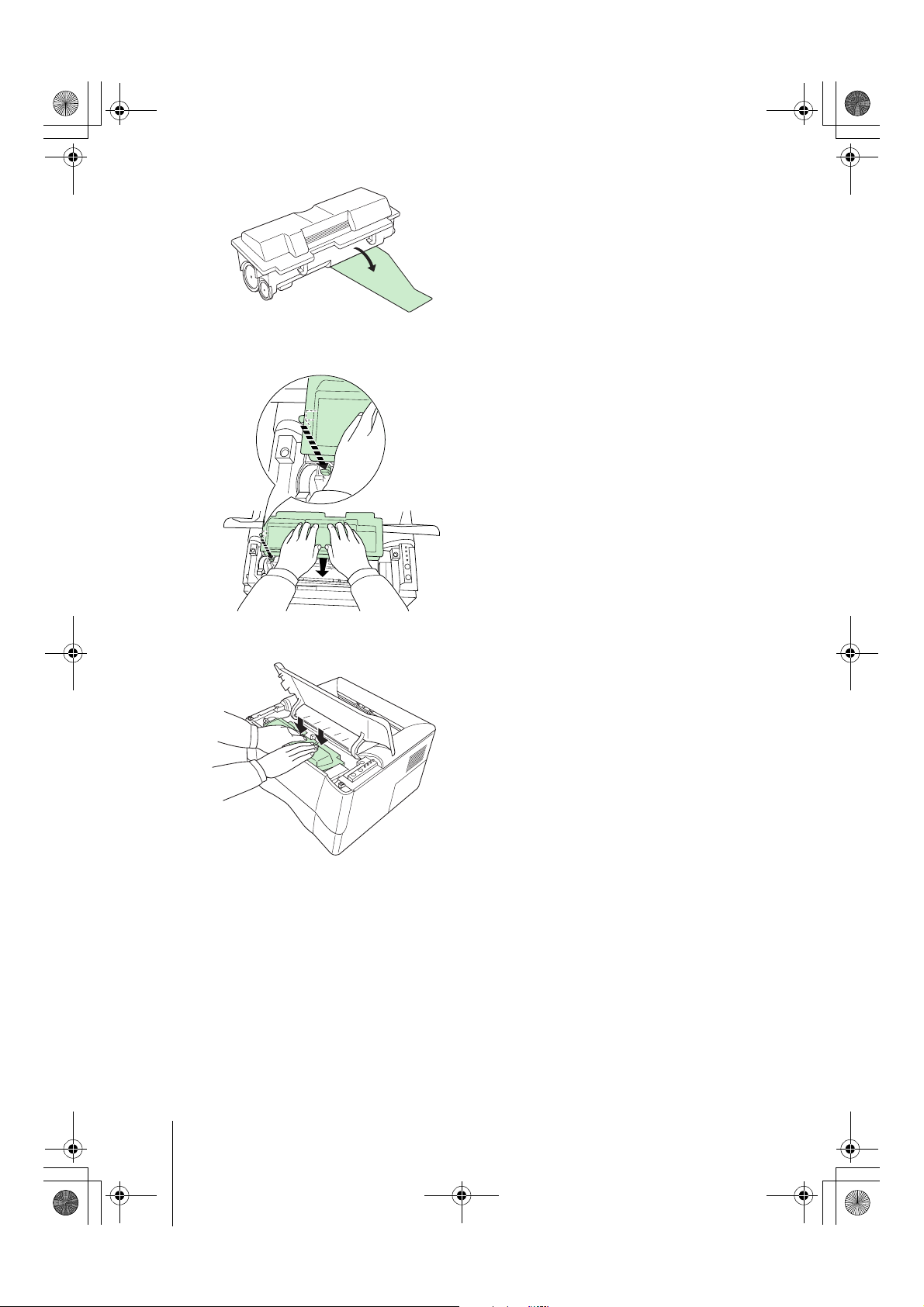
4
Carefully remove the protective seal.
5
Install the toner container into the
printer.
6
Push firmly on the top of the toner container at the positions marked PUSH
HERE.
4
Ifs10ep-jp.book Page 5 Friday, December 22, 2000 4:27 PM
LOCK
UNLOCK
K
C
O
L
K
C
O
L
N
U
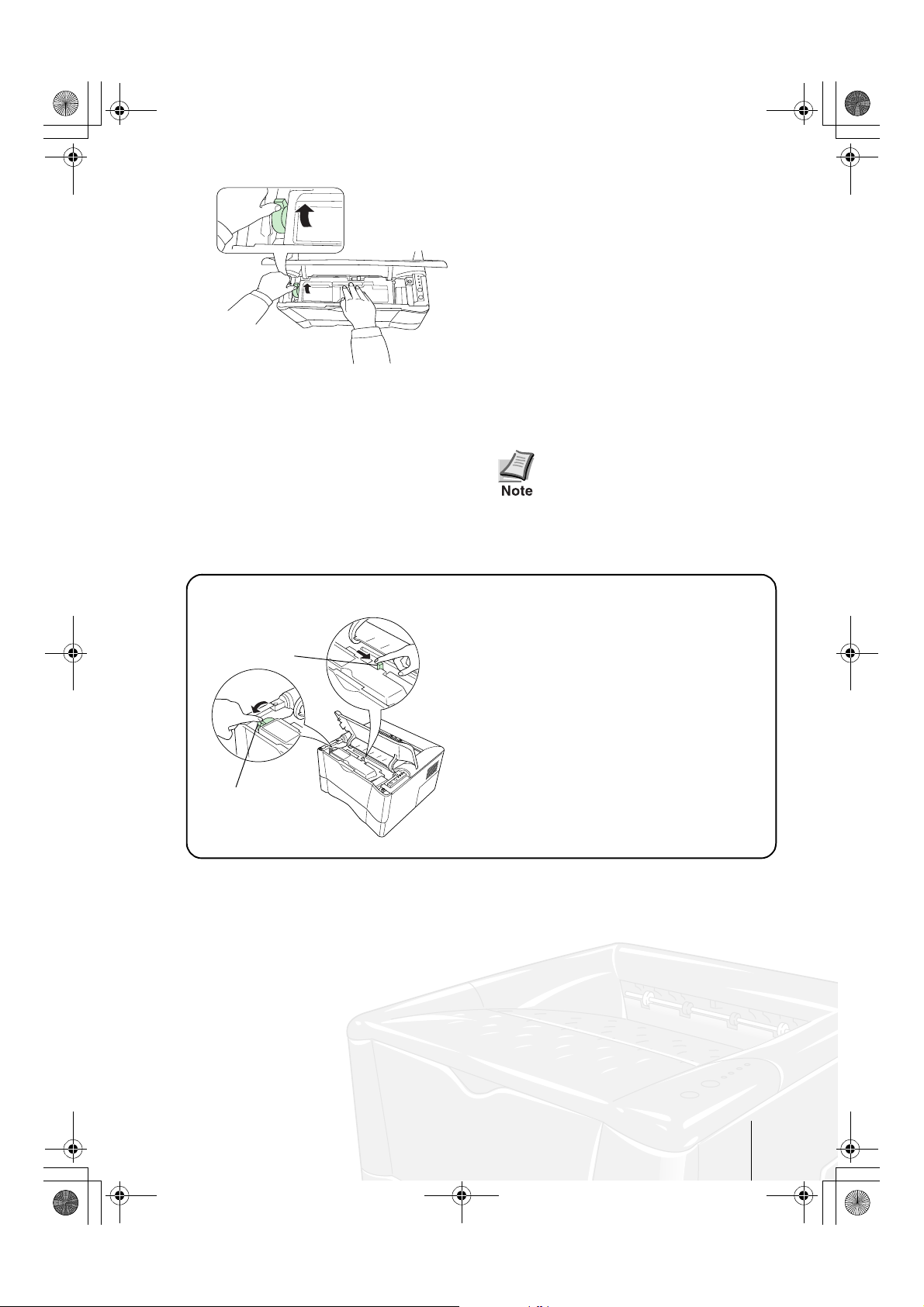
7
Push the lock lever to the lock (LOCK)
position.
8
Close the top cover.
When the printer is first
switched on after toner installation, there will be a delay of
approximately 15 minutes
before the printer gets ready to
print.
To remove the toner container
Lock Lever #2
Lock Lever #1
Pull the lock lever #1 to the release
(UNLOCK) position, pull the lock lever
#2, then gently remove the toner container.
Go to nex t pa ge
☞
5
Ifs10ep-jp.book Page 6 Friday, December 22, 2000 4:27 PM
STEP
Connecting the Printer to the Computer
There are various ways of connecting the printer to the computer, such as through the
4
parallel interface connector or through the optional network interface board.
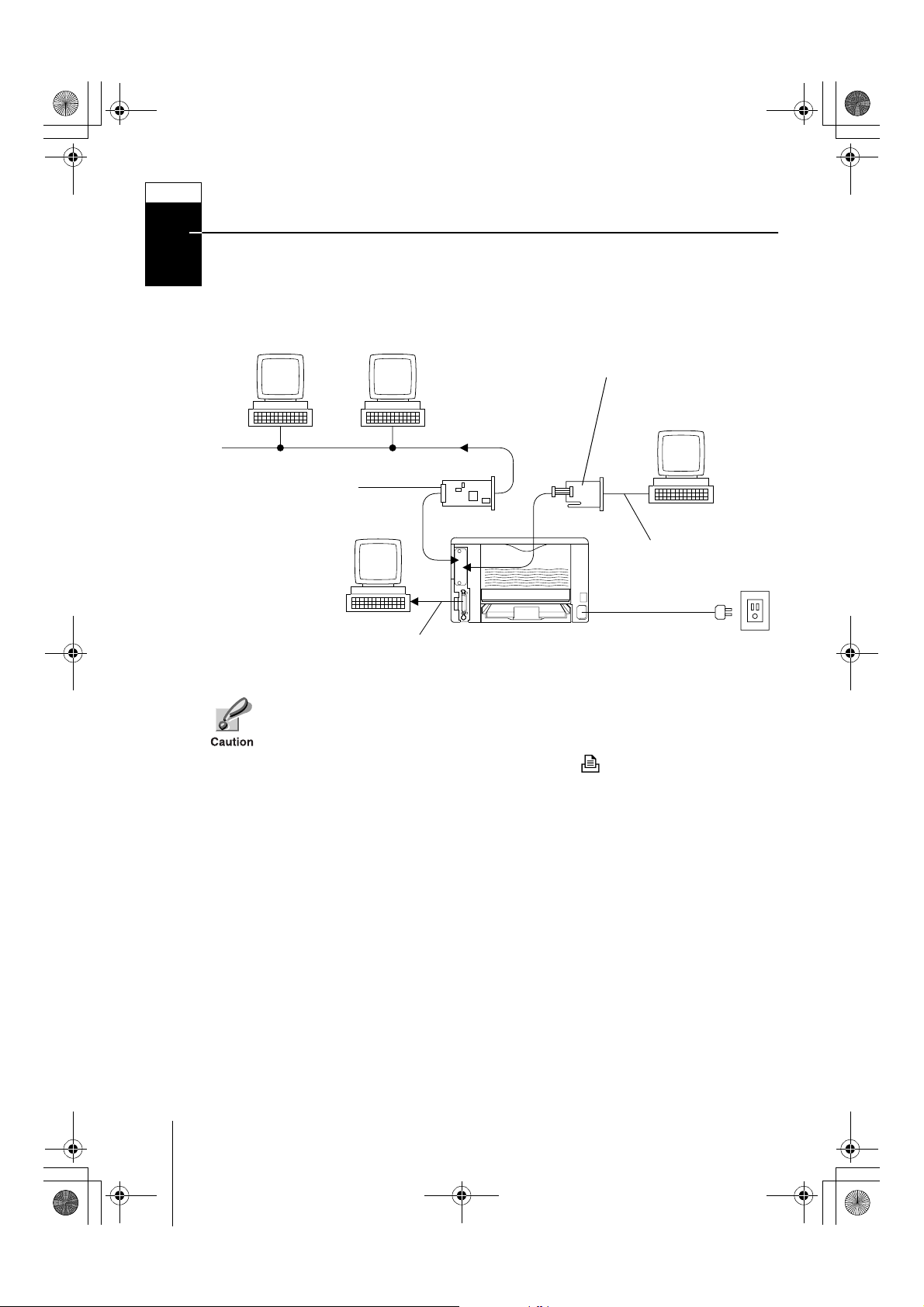
Printer Connections
Network
Optional Network
Interface Board
(DC 3.3V)
Optional Serial Interface
Board kit (IB-10E)
Serial Interface
Parallel Interface
Before performing this step, be sure to turn off both the printer and the computer’s power switches and unplug the printer’s power plug from the power
outlet. Failure to do so may result in electrical shock.
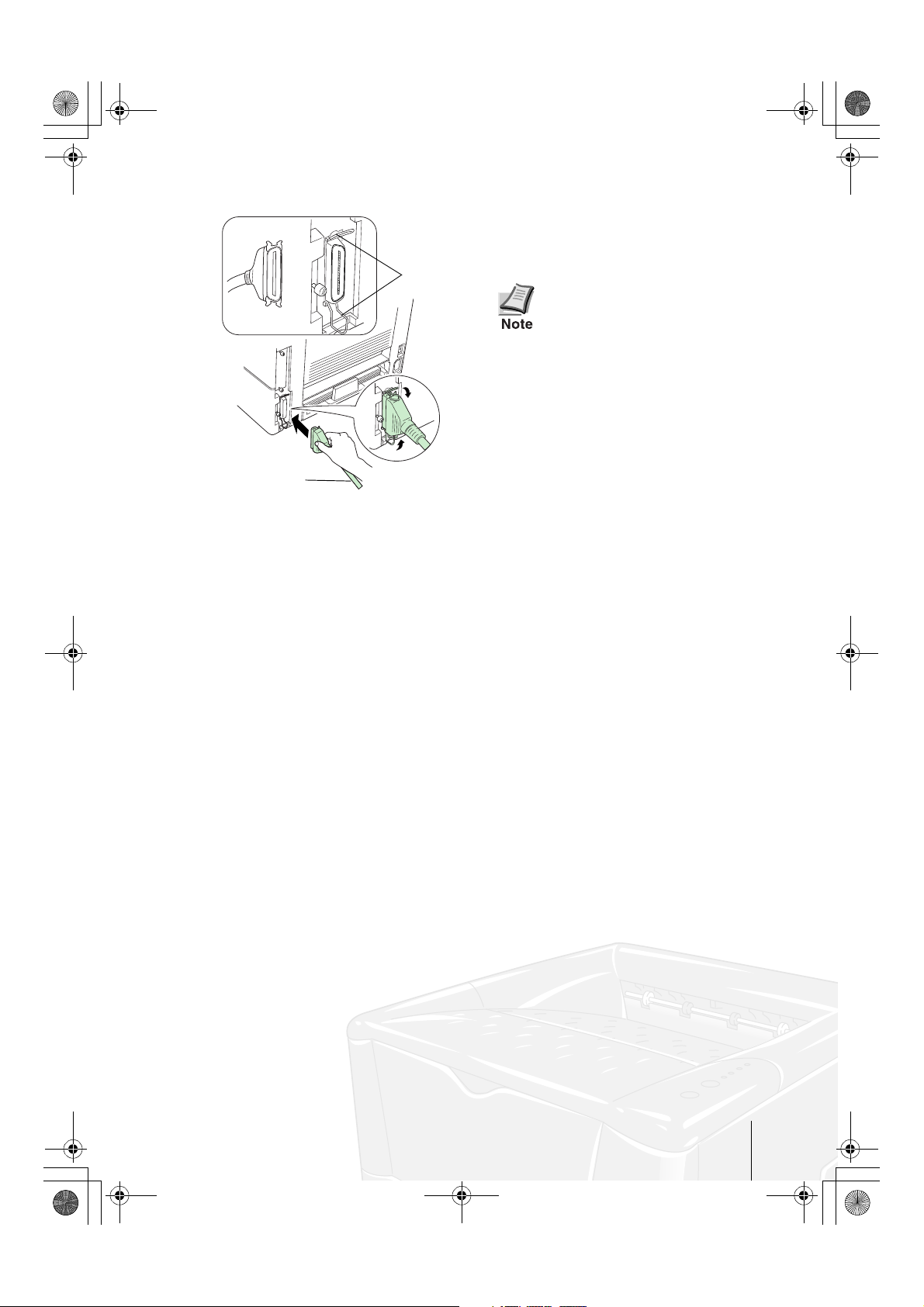
A standard Centronics parallel interface connector ( ) is located on the rear of
the printer.
Printer (Rear)
Power Supply
6
Ifs10ep-jp.book Page 7 Friday, December 22, 2000 4:27 PM
Parallel Interface Connection
To p ri nt er
Printer Cable
Clips
1
Plug one end of the printer cable (not
included) into the parallel interface connector on the rear of the printer.
• Use a parallel printer cable
that complies with the
IEEE1284 standards.
• The printer will work best if it
is instal led near the computer.
The connecting cable should
be shielded and not be longer
than 3 meters (10 feet).
2
Close the clips on both sides to fix the
connector in place.
Plug the other end of the printer cable
into the computer’s Centronics parallel
interface connector.
Go to nex t pa ge
☞
7
Ifs10ep-jp.book Page 8 Friday, December 22, 2000 4:27 PM
STEPSTEP
Connecting the Power Cord
This section describes the procedure for connecting the power cable and various
5
cautions.
Notes on Power Supply
• Install the printer near an AC wall outlet, preferably one that can be used for
the printer alone.
• Only use this printer with the supply voltage indicated on the serial number
label attached to the printer’s rear panel.
• If an extension cord is used, the total length of the power cord plus extension
should be 5 meters (17 feet) or less.
Power Requirements
Voltage
Frequency
Current capacity
120 V (U.S.A. and Canada), 220 to 240 V (European countries, and the
Asia-Pacific region), ±10 % at each voltage
60 Hz (120 V) ±2 %, 50/60 Hz (220 to 240 V) ±2 %
Max. 4.4 A at 120 V, or max. 2.2 A at 230 V
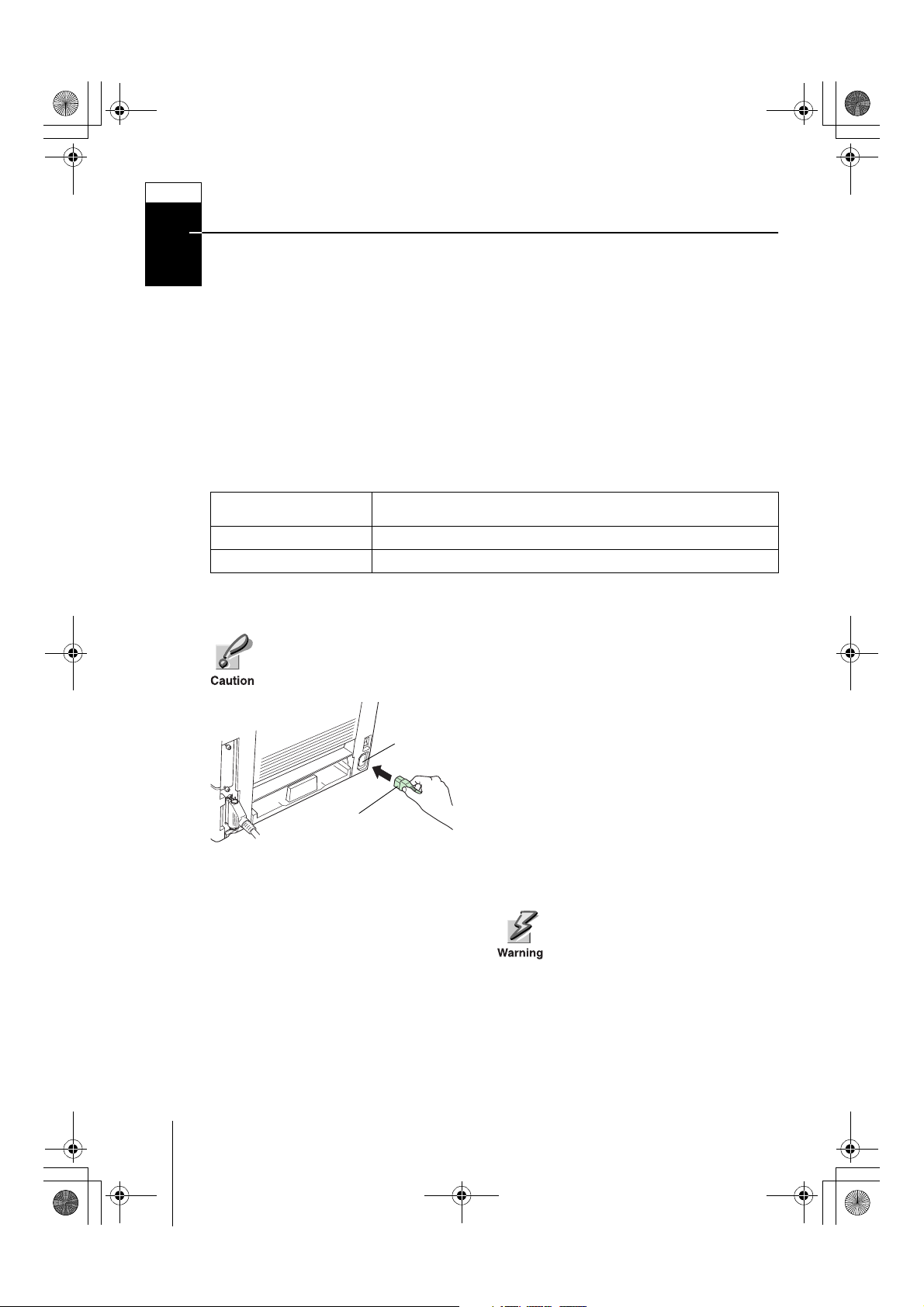
To Connect the Power Cord
• Be sure the printer’s power switch is turned off.
• Only use the power cord supplied with the printer.
Power Cord
Connector
Power Cord
1
2
Plug the power cord into the power cord
connector on the rear of the printer.
Connect the other end of the power cord
into a power outlet.
Be sure to connect to a 3-wire
grounded power strip.
8
 Loading...