

Page 1

DF-650(B)/MT-1(B)/BF-1(B)/PH-4(A)/PH-4(C)
620/820
DF-650(B)/MT-1(B)/BF-1(B)/PH-4(A)/PH-4(C)
Operation Guide
Manuel d'utilisation
Guía de uso
Einführung
Guida alle funzioni
Page 2

Page 3

DF-650, MT-1(A), BF-1(A), PH-4A AND PH-4C OPERATION GUIDE i
1 English
Safety Information . . . . . . . . . . . . . . . . . . . . . . . . . . . . . . . . . . . . . . . . . . . . . . . . . . . . . 1-1
Names of Parts . . . . . . . . . . . . . . . . . . . . . . . . . . . . . . . . . . . . . . . . . . . . . . . . . . . . . . . 1-6
Modes . . . . . . . . . . . . . . . . . . . . . . . . . . . . . . . . . . . . . . . . . . . . . . . . . . . . . . . . . . . . . . 1-7
Maintenance. . . . . . . . . . . . . . . . . . . . . . . . . . . . . . . . . . . . . . . . . . . . . . . . . . . . . . . . . 1-16
Troubleshooting . . . . . . . . . . . . . . . . . . . . . . . . . . . . . . . . . . . . . . . . . . . . . . . . . . . . . . 1-19
Specifications . . . . . . . . . . . . . . . . . . . . . . . . . . . . . . . . . . . . . . . . . . . . . . . . . . . . . . . . 1-32
2 Deutsch
Sicherheitshinweise . . . . . . . . . . . . . . . . . . . . . . . . . . . . . . . . . . . . . . . . . . . . . . . . . . . . 2-1
Bezeichnung der Teile . . . . . . . . . . . . . . . . . . . . . . . . . . . . . . . . . . . . . . . . . . . . . . . . . . 2-6
Betriebsarten . . . . . . . . . . . . . . . . . . . . . . . . . . . . . . . . . . . . . . . . . . . . . . . . . . . . . . . . . 2-7
Wartung . . . . . . . . . . . . . . . . . . . . . . . . . . . . . . . . . . . . . . . . . . . . . . . . . . . . . . . . . . . . 2-16
Störungsbeseitigung. . . . . . . . . . . . . . . . . . . . . . . . . . . . . . . . . . . . . . . . . . . . . . . . . . . 2-19
Technische Daten. . . . . . . . . . . . . . . . . . . . . . . . . . . . . . . . . . . . . . . . . . . . . . . . . . . . . 2-32
3 Español
Información de seguridad. . . . . . . . . . . . . . . . . . . . . . . . . . . . . . . . . . . . . . . . . . . . . . . . 3-1
Nombres de las piezas. . . . . . . . . . . . . . . . . . . . . . . . . . . . . . . . . . . . . . . . . . . . . . . . . . 3-6
Modos . . . . . . . . . . . . . . . . . . . . . . . . . . . . . . . . . . . . . . . . . . . . . . . . . . . . . . . . . . . . . . 3-7
Mantenimiento . . . . . . . . . . . . . . . . . . . . . . . . . . . . . . . . . . . . . . . . . . . . . . . . . . . . . . . 3-16
Solución de problemas. . . . . . . . . . . . . . . . . . . . . . . . . . . . . . . . . . . . . . . . . . . . . . . . . 3-19
Especificaciones . . . . . . . . . . . . . . . . . . . . . . . . . . . . . . . . . . . . . . . . . . . . . . . . . . . . . 3-32
4Français
Informations de sécurité. . . . . . . . . . . . . . . . . . . . . . . . . . . . . . . . . . . . . . . . . . . . . . . . . 4-1
Nom des pièces . . . . . . . . . . . . . . . . . . . . . . . . . . . . . . . . . . . . . . . . . . . . . . . . . . . . . . . 4-6
Modes . . . . . . . . . . . . . . . . . . . . . . . . . . . . . . . . . . . . . . . . . . . . . . . . . . . . . . . . . . . . . . 4-7
Entretien. . . . . . . . . . . . . . . . . . . . . . . . . . . . . . . . . . . . . . . . . . . . . . . . . . . . . . . . . . . . 4-16
Dépannage. . . . . . . . . . . . . . . . . . . . . . . . . . . . . . . . . . . . . . . . . . . . . . . . . . . . . . . . . . 4-19
Spécifications . . . . . . . . . . . . . . . . . . . . . . . . . . . . . . . . . . . . . . . . . . . . . . . . . . . . . . . . 4-32
5Italiano
Informazioni sulla sicurezza . . . . . . . . . . . . . . . . . . . . . . . . . . . . . . . . . . . . . . . . . . . . . . 5-1
Nomi delle parti . . . . . . . . . . . . . . . . . . . . . . . . . . . . . . . . . . . . . . . . . . . . . . . . . . . . . . . 5-6
Modalità . . . . . . . . . . . . . . . . . . . . . . . . . . . . . . . . . . . . . . . . . . . . . . . . . . . . . . . . . . . . . 5-7
Manutenzione. . . . . . . . . . . . . . . . . . . . . . . . . . . . . . . . . . . . . . . . . . . . . . . . . . . . . . . . 5-16
Risoluzione dei problemi . . . . . . . . . . . . . . . . . . . . . . . . . . . . . . . . . . . . . . . . . . . . . . . 5-19
Specifiche. . . . . . . . . . . . . . . . . . . . . . . . . . . . . . . . . . . . . . . . . . . . . . . . . . . . . . . . . . . 5-32
Page 4

ii DF-650, MT-1(A), BF-1(A), PH-4A AND PH-4C OPERATION GUIDE
Page 5
DF-650(B), MT-1(B), BF-1(B), PH-4(A) AND PH-4(C) OPERATION GUIDE 1-1
1 English
Safety Information
Please read the Operation Guide before using this product. After reading, keep it
close to the machine for easy reference.
Refer to the Operation Guide for the machine for information on the service
representative for your product.
The sections of this Operation Guide and parts of this product marked with symbols
are safety warnings meant to protect the user, other individuals and surrounding
objects, and ensure correct and safe usage of the product.
The symbols and their meanings are indicated below..
Symbols
The symbol indicates that the related section includes safety warnings. Specific
points of attention are indicated inside the symbol.
The symbol indicates that the related section includes information on prohibited
actions. Specifics of the prohibited action are indicated inside the symbol.
WARNING: Indicates that serious injury or even death may result from
insufficient attention to or incorrect compliance with the related points.
CAUTION: Indicates that personal injury or mechanical damage may result
from insufficient attention to or incorrect compliance with the related points.
.... [General warning]
....
[Warning of prohibited action]
....
[Disassembly prohibited]
Page 6

English
1-2 DF-650(B), MT-1(B), BF-1(B), PH-4(A) AND PH-4(C) OPERATION GUIDE
The
z symbol indicates that the related section includes information on actions which
must be performed. Specifics of the required action are indicated inside the symbol.
Please contact your service representative to order a replacement if the safety
warnings in this Guide are illegible or if the guide itself is missing (fee required).
....
[Alert of required action]
....
[Remove the power plug from the outlet]
....
[Always connect the product to an outlet with a ground connection]
Page 7
English
DF-650(B), MT-1(B), BF-1(B), PH-4(A) AND PH-4(C) OPERATION GUIDE 1-3
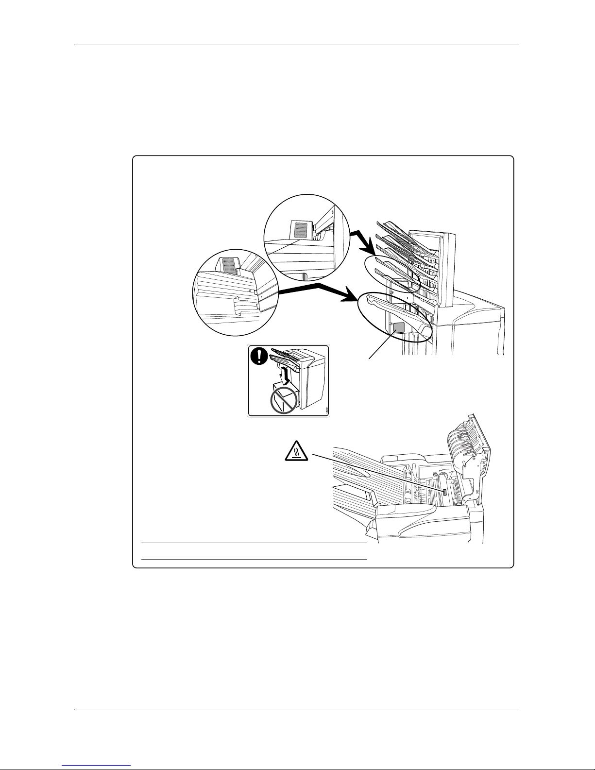
CAUTION LABELS
Caution labels have been attached to the Document Finisher at the following
locations for safety purposes. BE VERY CAREFUL to avoid getting your fingers
caught in or burned by the machine when clearing a paper jam.
LABEL 2
DO NOT place any objects underneath Tray A.
LABEL 3
The interior of this section reaches high
temperatures. DO NOT touch this
section as there is a danger of being
burned.
LABEL 1
WARNING: To avoid injury to your hands, wait until the copier stops before removing paper.
NOTE: DO NOT REMOVE THESE LABELS.
Page 8
English
1-4 DF-650(B), MT-1(B), BF-1(B), PH-4(A) AND PH-4(C) OPERATION GUIDE
INSTALLATION PRECAUTIONS
Environment
CAUTION
Avoid placing this product on or in locations which are unstable or not level.
Such locations may cause the product to fall down or fall over. This type of
situation presents a danger of personal injury or damage to the product.
Avoid locations near radiators, heaters, or other heat sources, or locations
near flammable items, to avoid the danger of fire.
Other precautions
The requirements for the operating environment are as follows:
• Temperature: 0°C to 35°C (32°F to 95°F)
• Humidity: 15% to 80%
Note that ambient environmental conditions, such as ventilation, may affect
performance.
The following locations should be avoided:
• Avoid locations near a window or with exposure to direct sunlight.
• Avoid locations with vibrations.
• Avoid locations with drastic temperature fluctuations.
• Avoid locations with direct exposure to hot or cold air.
Handling of plastic bags
WARNING
Keep the plastic bags that are used with this product away from children. The
plastic may cling to their nose and mouth causing suffocation.
PRECAUTIONS FOR USE
Cautions when using this product
WARNING
DO NOT place metallic objects or containers with water (flower vases, flower
pots, cups, etc.) on or near this product. This type of situation presents a
danger of fire or electrical shock should any water fall inside.
DO NOT damage, break or attempt to repair the power cable. DO NOT place
heavy objects on the power cable, pull it, bend it unnecessarily or cause any
other type of damage. These types of situations present a danger of fire or
electrical shock..
Page 9
English
DF-650(B), MT-1(B), BF-1(B), PH-4(A) AND PH-4(C) OPERATION GUIDE 1-5
NEVER attempt to repair or disassemble this product or its parts as there is a
danger of injury or fire or electrical shock.
If this product becomes excessively hot, smoke appears, there is an odd smell,
or any other abnormal situation arises, there is a danger of fire or electrical
shock. Immediately turn OFF the machine’s main power switch, remove the
machine’s power plug from its outlet and contact your service representative.
If anything harmful (paper clips, water, other fluids, etc.) falls into this product,
immediately turn the machine OFF at the main power switch, remove the
copier/printer power plug from its outlet and then contact your service
representative. If you continue to use this product without taking these steps,
there is a danger of fire or electrical shock.
ALWAYS contact your service representative for maintenance or repair of
internal parts.
CAUTION
For safety purposes, ALWAYS turn OFF the machine’s main power switch
and remove the machine’s power plug from its outlet when performing
cleaning operations on this product.
DO NOT touch the ejection tray when the product is in operation as there is a
danger of injury.
If dust accumulates within this product, there is a danger of fire or other
trouble. It is therefore recommended that you consult with your service
representative in regard to cleaning of internal parts. This is particularly
effective if accomplished prior to seasons of high humidity. Consult with your
service representative in regard to the cost of cleaning the internal parts of the
product as well.
Other Precautions
DO NOT place heavy objects on this product or cause other damage to the product.
When lifting or moving the product, contact your service representative.
Do not touch electrical parts, such as connectors or printed circuit boards. They
could be damaged by static electricity.
DO NOT attempt to perform any operations not explained in this Operation Guide.
Page 10
English
1-6 DF-650(B), MT-1(B), BF-1(B), PH-4(A) AND PH-4(C) OPERATION GUIDE
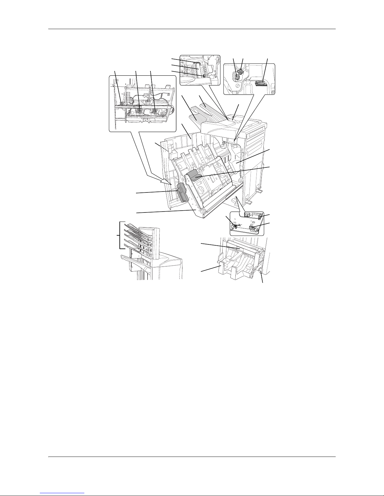
Names of Parts
Document Finisher (main body) Center-Folding Unit (option)
1 Tray A
2 Tray B
3 Front cover
4 Front cover handle
5 Upper cover
6 Internal tray
7 Internal tray lever (G3)
8 Internal tray release lever
(G4)
9 Pressure roller adjuster (G5)
10 Conveyor knob (G1)
11 Coupling section's lower guide
lever (G2)
12 Staple cartridge holder A
13 Staple cartridge holder B
14 Coupling section's upper
guide lever
18 Unit release lever (G6)
19 Unit release handle (G7)
20 Center-Folding Unit lock release
lever
21 Center-Folding Unit installation
buttons
22 Conveyor guide lever
23 Storage cover
Hole Punch Unit (option)
15 Hole Punch Unit (main
body)
16 Hole Punch Unit
adjustment dial
17 Waste Hole Punch box
Multi-Job Tray Unit (option)
24 Job Trays 1 - 5
910 11
18
8
20
19
21
23
24
17
12
16
15
13 14
25
5
21
3
4
7
6
22
Page 11
English
DF-650(B), MT-1(B), BF-1(B), PH-4(A) AND PH-4(C) OPERATION GUIDE 1-7
Modes
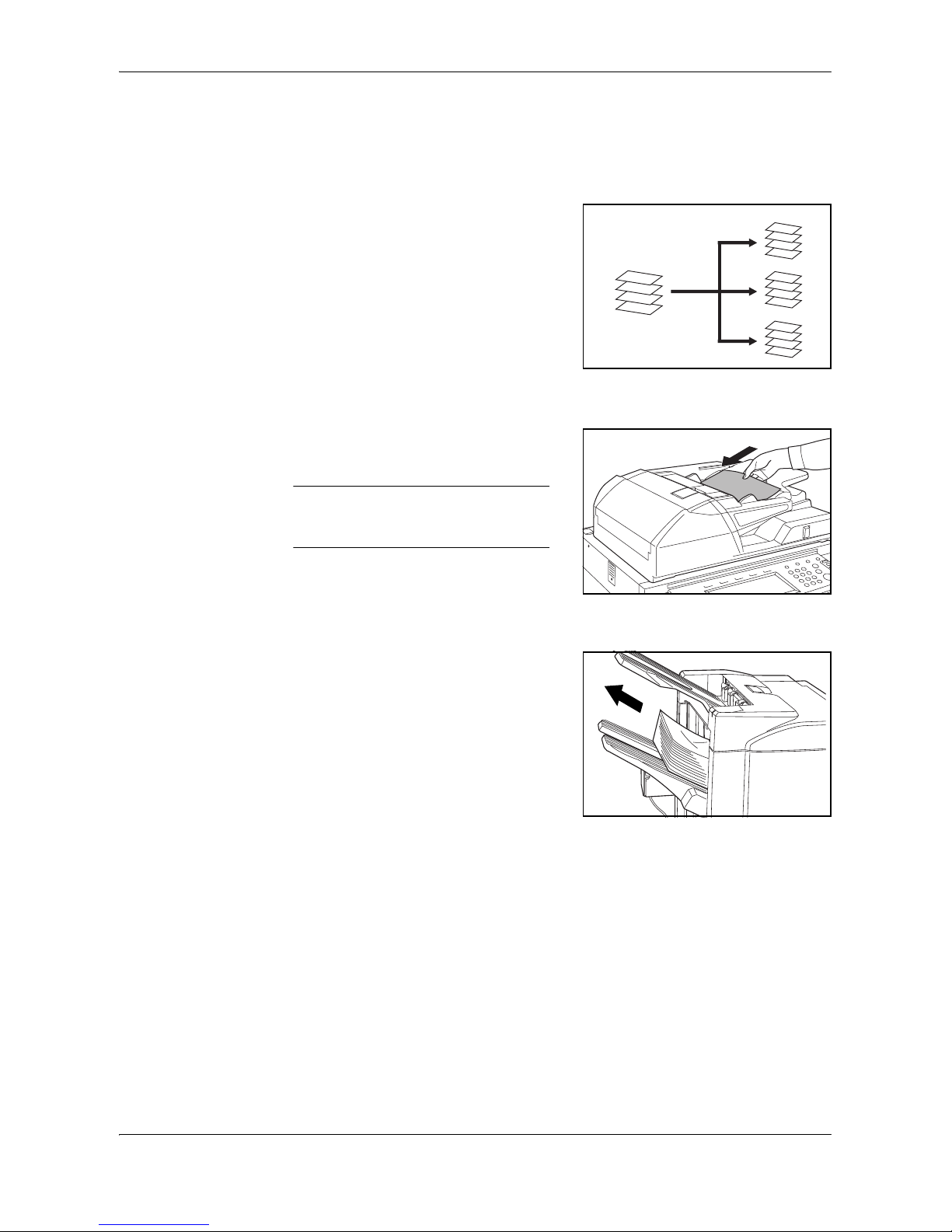
Sort: ON Mode
Sorts copies of multiple originals into
identical sets. For example A,B,C,D
A,B,C,D A,B,C,D.
The following paper sizes can be used in
Sort:ON Mode:
• A3, B4, A4, A4R, B5,11 x 17",
8 1/2 x 14" (Legal), 8 1/2 x 11" (Letter)
and 11 x 8 1/2".
1
Select Sort: On Mode on the operation panel of your copier.
2
Load the originals in the Document
Processor, or one at a time on the Platen.
NOTE: Refer to the Operation Guide
for your copier for Document Processor
and Platen specifications.
3
Select other features as required and press Start.
4
Copies are ejected onto the specified tray.
If Tray A is selected, each copy set can be
offset from the previous set. Refer to the
Operation Guide for your copier for further
details.
D
C
B
A
D
C
B
A
D
C
B
A
D
C
B
A
Page 12

English
1-8 DF-650(B), MT-1(B), BF-1(B), PH-4(A) AND PH-4(C) OPERATION GUIDE
If Tray A and Tray B both reach their maximum capacity, a message displays.
Remove all copies from both trays to continue.
NOTE: The maximum number of copies that can be stored on Tray A and Tray B
differs depending on the size of copy paper being used. For further information refer
to Tray Capacity on page 1-32.
5
On completion of the job, remove the copies.
Sort: OFF Mode
Groups the copies of each individual
original together in one stack. For example
A,A,A B,B,B C,C,C.
The following paper sizes can be used in
Sort:OFF Mode:
• A3, B4, A4, A4R, B5,11 x 17",
8 1/2 x 14" (Legal), 8 1/2 x 11" (Letter)
and 11 x 8 1/2".
1
Select Sort: Off Mode on the operation panel of your copier.
2
Load the originals in the Document
Processor, or one at a time on the Platen.
NOTE: Refer to the Operation Guide
for your copier for Document Processor
and Platen specifications.
3
Select other features as required and press Start.
C
B
A
C
C
C
B
B
B
A
A
A
Page 13
English
DF-650(B), MT-1(B), BF-1(B), PH-4(A) AND PH-4(C) OPERATION GUIDE 1-9
4
Copies are ejected onto the specified tray.
If Tray A is selected, each stack can be
offset from the previous stack. Refer to the
Operation Guide for your copier for further
details.
If Tray A and Tray B both reach their
maximum capacity, a message displays.
Remove all copies from both trays to
continue.
NOTE: The maximum number of copies that can be stored on Tray A and Tray B
differs depending on the size of copy paper being used. For further information refer
to Tray Capacity on page 1-32. If the number of copies to be made at one time in
Non-Sort Mode exceeds the maximum capacity for Tray B (200 sheets), all copies
thereafter are ejected onto Tray A.
5
On completion of the job, remove the copies.
Staple Mode
Sorts and staples each copy set.
Stapling options are as follows:
• Upper Left Single Staple
• Upper Right Single Staple
• Double Staple
NOTE: For stapling specifications, refer to Staple Unit on page 1-32.
1
Select Sort: On Mode on the operation panel of your copier.
2
Select the staple setting required.
D
C
B
A
D
C
B
A
D
C
B
A
D
C
B
A
A
A
A A
A AA
A
AA
A
A
A
A
Page 14

English
1-10 DF-650(B), MT-1(B), BF-1(B), PH-4(A) AND PH-4(C) OPERATION GUIDE
3
Load the originals in the Document
Processor, or one at a time on the Platen.
NOTE: Refer to the Operation Guide
for your copier for Document Processor
and Platen specifications.
4
Select other features as required and press Start.
5
Copies will be stapled and ejected onto Tray
A, face down.
If Tray A reaches its maximum capacity, a
message displays. Remove all copies from
Tray A to continue.
NOTE: The maximum number of copies that can be stored on Tray A differs
depending on the size of copy paper being used. For further information refer to
Tray Capacity on page 1-32.
6
On completion of the job, remove the copies.
Non-Sort Mode
Use this mode when sorting or grouping are
not required.
ALWAYS use Non-Sort Mode when copying
onto transparencies or other special
material or paper.
C
B
D
A
E
C
B
D
A
E
Page 15
English
DF-650(B), MT-1(B), BF-1(B), PH-4(A) AND PH-4(C) OPERATION GUIDE 1-11
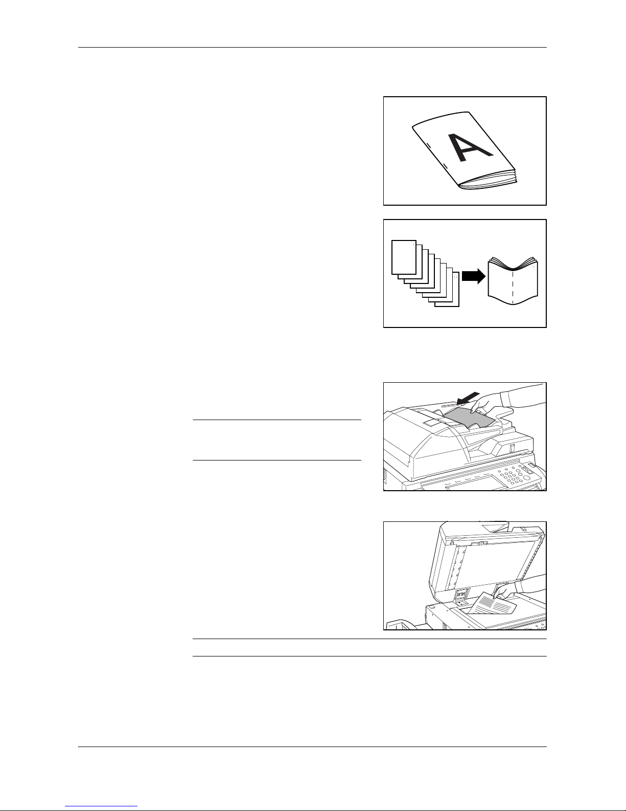
Booklet Stitching Mode
In this mode, copies are stapled in two
positions in the center of the paper.
The following paper sizes can be used in
Booklet Stitching mode:
• A3, B4, A4R, 11 x 17", 8 1/2 x 14"
(Legal) and 11 x 8 1/2".
Stapling Capacity: 2 to 16 sheets at a time.
The optional Center-Folding Unit is required
for automatic folding.
The Booklet Copy function on your copier
can be used to automatically produce
booklets ready for stitching and folding.
Refer to the Operation Guide for your copier
for more information.
1
Select the Booklet Stitching mode on the operation panel of your copier.
Refer to the Operation Guide for your copier for more detailed information.
2
Load the originals in the Document
Processor, or one at a time on the Platen.
NOTE: Refer to the Operation Guide
for your copier for Document Processor
and Platen specifications.
The maximum number of sheets that can be
stitched at one time is 16. Up to 64 originals
can be used in this mode.
3
Select other features as required and press
Start.
If using the Platen, a message displays after
each original is scanned to determine
whether another original requires scanning
or if copying can commence.
NOTE: Refer to the Operation Guide for your copier for further details.
Page 16

English
1-12 DF-650(B), MT-1(B), BF-1(B), PH-4(A) AND PH-4(C) OPERATION GUIDE
4
Copies will be automatically stapled and
ejected onto the storage cover.
If the maximum capacity is reached, a
message displays. Remove all copies from
the storage cover to continue.
NOTE: For further information refer to Center-Folding Unit (option) on page 1-33.
5
On completion of the job, remove the copies
from the storage cover.
Hole Punch Mode
The Hole Punch Unit is an optional device.
This mode produces hole punched copies
automatically.
The following paper sizes can be used:
• 2-hole punch: A3, B4, A4, A4R, B5,
B5R, A5R, Folio, 8 1/2 x 14" (Legal),
8 1/2 x 11" (Letter) and 5 1/2 x 8 1/2"
• 3-hole punch: 11 x 17" and 11 x 8 1/2"
• 4-hole punch: A3 and A4
Hole Punch mode can be used with Sort: ON, Staple and Sort: OFF modes. Paper
weights must be between 45 g/m
2
and 200 g/m2.
NOTE: B5R can only be selected if copies are ejected onto Tray A. In Sort: ON
mode and Staple mode, B5R and Folio cannot be selected.
1
Select Hole Punch mode on the operation panel of your copier.
NOTE: Refer to the Operation Guide for your copier for more detailed information.
Page 17
English
DF-650(B), MT-1(B), BF-1(B), PH-4(A) AND PH-4(C) OPERATION GUIDE 1-13
2
Load the originals in the Document
Processor, or one at a time on the Platen.
Ensure the orientation of the originals is the
same as that selected for Hole Punch mode
on the copier.
NOTE: Refer to the Operation Guide for your copier for Document Processor and
Platen specifications.
3
Select other features as required and press Start.
4
The copies are automatically hole punched
and ejected onto Tray B.
NOTE: Holes are punched in each
copy individually, therefore the location
of the holes may vary on each sheet.
On completion of the job, remove all the
copies.
NOTE: If the maximum capacity for Tray B is exceeded, all subsequent copies will
be ejected onto Tray A. If Tray A is not engaged when Tray B becomes full, an error
message displays. Remove all copies to continue.
Interrupt Mode
When using Interrupt Mode, the copies for the interrupt job are usually ejected onto
the finisher tray not currently in use. If required, a different tray can be selected on
the copier Operation Panel.
NOTE: Refer to the Operation Guide for your copier for further details.
Page 18

English
1-14 DF-650(B), MT-1(B), BF-1(B), PH-4(A) AND PH-4(C) OPERATION GUIDE
Multi-Job Tray Mode
The Multi-Job Tray Unit is an optional
device. Print or Copy output can be ejected
into a specified Multi-Job Tray.
This option is extremely useful when more
than one user is using the copier as a
printer. The printed documents for each
user will be ejected into the job tray
selected.
The following paper sizes can be used:
• Plain paper (80 g/m
2
): between A3 and B6R, or Folio, 11 x 17" and 8 1/2 x 11"
• Recycled paper (80 g/m
2
): A3, A4, A4R, 11 x 17", 11 x 8 1/2" and 8 1/2 x 11"
• Colored paper (80 g/m
2
): A4, A4R, 8 1/2 x 11" and 11 x 8 1/2"
NOTE: The maximum number of copies that can be stored in each job tray will
differ depending on the size of copy paper being used. For further information refer
to Multi-Job Tray Unit (option) on page 1-33.
1
Write the name of the user of each job tray
on the labels provided.
2
Attach the labels to the job trays, in the
location indicated on the illustration.
The trays to which labels should be applied
are 1, 2, 3, 4, and 5, as counted from the top
down.
3
Use the application in your computer to select a job tray between 1 and 5.
4
Select the paper size, page(s) to be printed and number of prints required.
Page 19

English
DF-650(B), MT-1(B), BF-1(B), PH-4(A) AND PH-4(C) OPERATION GUIDE 1-15
5
Print the job.
Prints will be ejected onto the selected job
tray.
6
On completion of the job, remove all prints from the job tray.
NOTE: To use the copier to select the tray required, refer to the Operation Guide
for your copier.
Page 20
English
1-16 DF-650(B), MT-1(B), BF-1(B), PH-4(A) AND PH-4(C) OPERATION GUIDE
Maintenance
Replacing Staples
The Document Finisher is equipped with two staple cartridge holders, A and B. The
procedure for replenishing staples is the same for both holders.
If a message displays indicating that staples have run out, the staple cartridge
holder(s) need to be replenished with staples.
NOTE: If the Staple Unit runs out of staples, contact your service representative or
the place of purchase.
1
Grasp the front cover handle and open the
front cover.
2
Turn internal tray lever G3 clockwise and
pull out the internal tray.
3
Lift up the staple cartridge holder and pull it
out.
4
Remove the empty staple cartridge from the
staple cartridge holder.
Page 21
English
DF-650(B), MT-1(B), BF-1(B), PH-4(A) AND PH-4(C) OPERATION GUIDE 1-17
5
Remove the new staple cartridge from its
box.
6
Holding the staple cartridge holder in one
hand and the new staple cartridge in the
other, insert the staple cartridge into the
holder.
Ensure the direction of insertion is correct.
Both arrows should point in the same
direction.
7
Ensure the new staple cartridge is inserted
completely into the staple cartridge holder,
then peel off the paper tape.
8
Re-install the staple cartridge holder.
The staple cartridge holder will click into
place when it has been inserted correctly.
9
Set the internal tray and turn the lever
upright. Close the cover.
Page 22

English
1-18 DF-650(B), MT-1(B), BF-1(B), PH-4(A) AND PH-4(C) OPERATION GUIDE
Emptying the Waste Hole Punch Box
If the message "Empty waste punch box" displays, the scraps in the waste hole
punch box require emptying.
Leave the main power switch on your copier switched ON ( | ) while performing this
procedure.
1
Grasp the front cover handle and open the
front cover.
2
Grasp the waste hole punch box handle and
remove the box from the Document
Finisher.
3
Dispose of the hole punch scraps
appropriately.
4
Re-install the waste hole punch box. Align it
with the guides in the Document Finisher.
5
Close the front cover.
Page 23
English
DF-650(B), MT-1(B), BF-1(B), PH-4(A) AND PH-4(C) OPERATION GUIDE 1-19
Troubleshooting
General
If ejected copies are not flat or are stacked
unevenly, turn over the paper in the
cassette and reload it.
If copies are curled, refer to Curled Output
on page 1-29.
If a paper jam occurs, check the side guide
located in the cassette is adjusted to the
size of paper loaded.
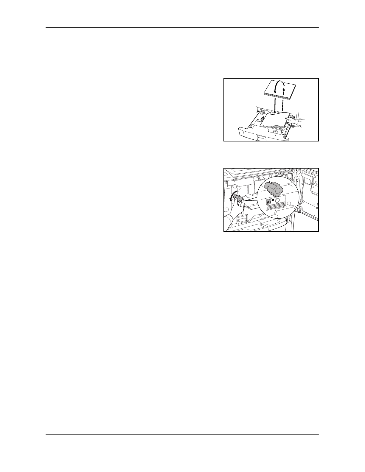
Clearing Paper Jams
Leave the main power switched ON ( | )
while performing the procedure to clear
paper jams.
Open the cover of the copier and turn the
fixer knob (A1) to the left at least 20 times
before carrying out the paper jam removal
procedure.
Once the jam is cleared, the operation panel
on your copier will return to the status and
settings prior to the jam.
Page 24
English
1-20 DF-650(B), MT-1(B), BF-1(B), PH-4(A) AND PH-4(C) OPERATION GUIDE
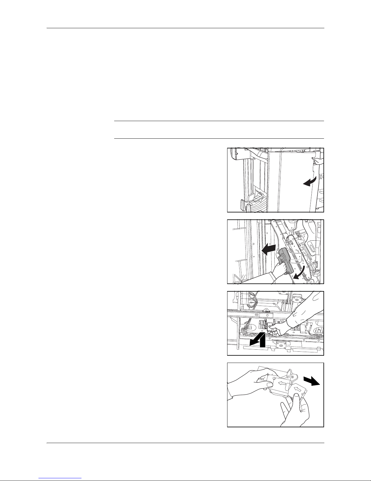
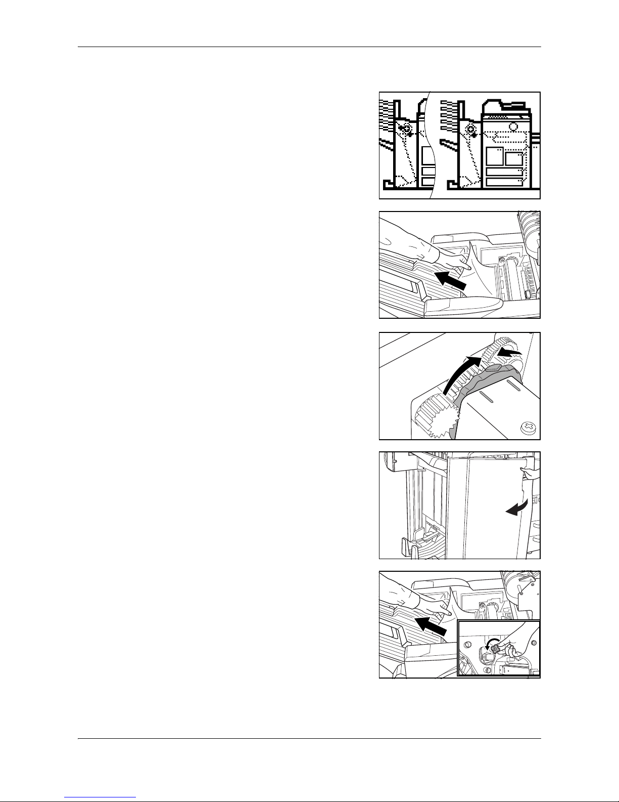
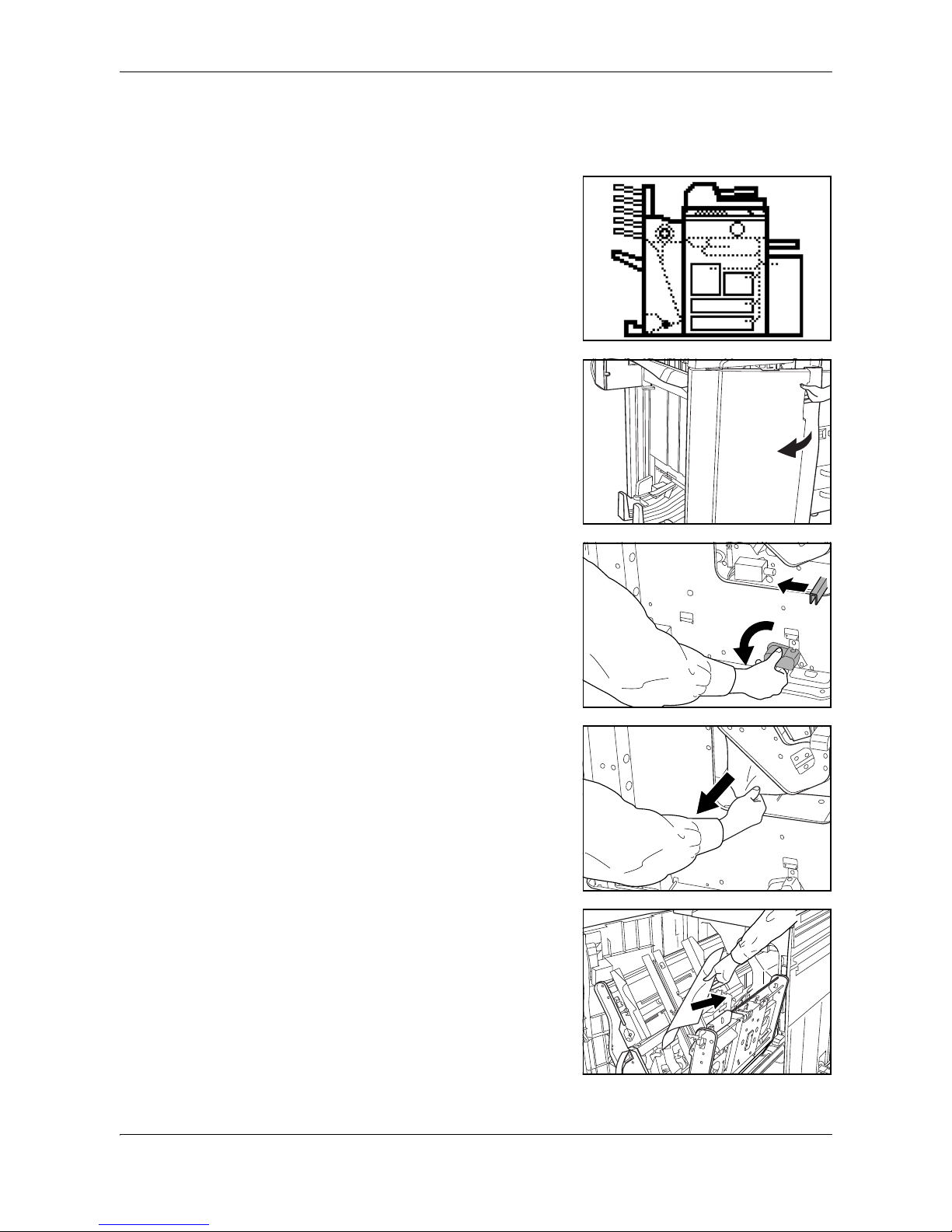
Paper Jam in the Coupling Section
If the illustration shown displays on the
operation panel of your copier, there is a
paper jam in the coupling section between
the Document Finisher and your copier.
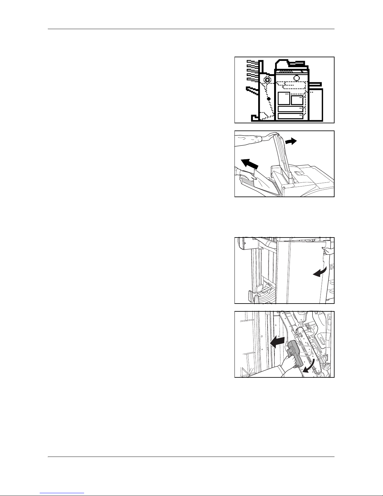
1
Open the upper cover and remove the
jammed paper.
If the jammed paper cannot be easily
removed, proceed to the next step.
If the optional Hole Punch Unit is installed,
ensure the arrow on the adjustment dial
points somewhere between the grooves on
the main body of the Hole Punch Unit.
2
Grasp the front cover handle and open the
front cover.
3
Turn the conveyor knob (G1) to feed the
paper further along to enable easy removal.
Remove the paper.
If the jammed paper cannot be easily
removed, proceed to the next step.
Page 25

English
DF-650(B), MT-1(B), BF-1(B), PH-4(A) AND PH-4(C) OPERATION GUIDE 1-21
4
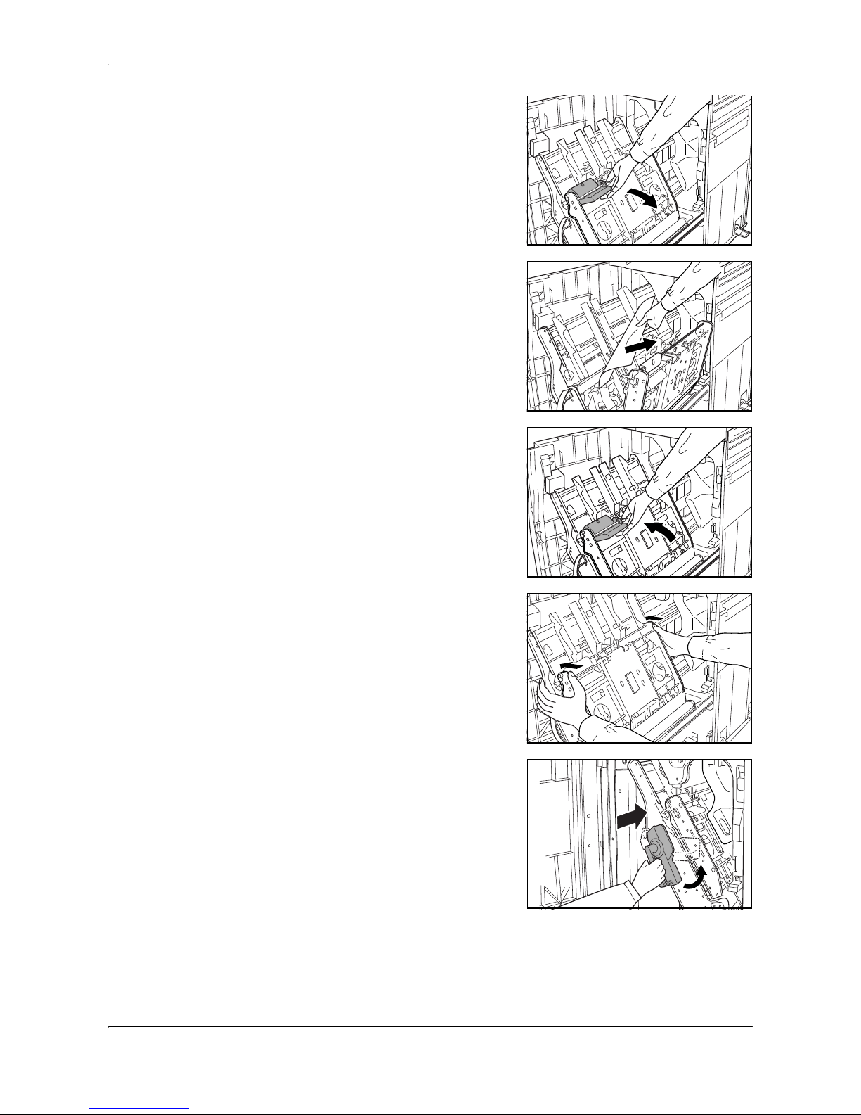
Lift the coupling section's upper guide lever
and remove the jammed paper.
Close the upper guide lever and the upper
cover.
5
Hold the coupling section's lower guide
lever (G2) and open.
Close the lower guide.
6
Close the front cover.
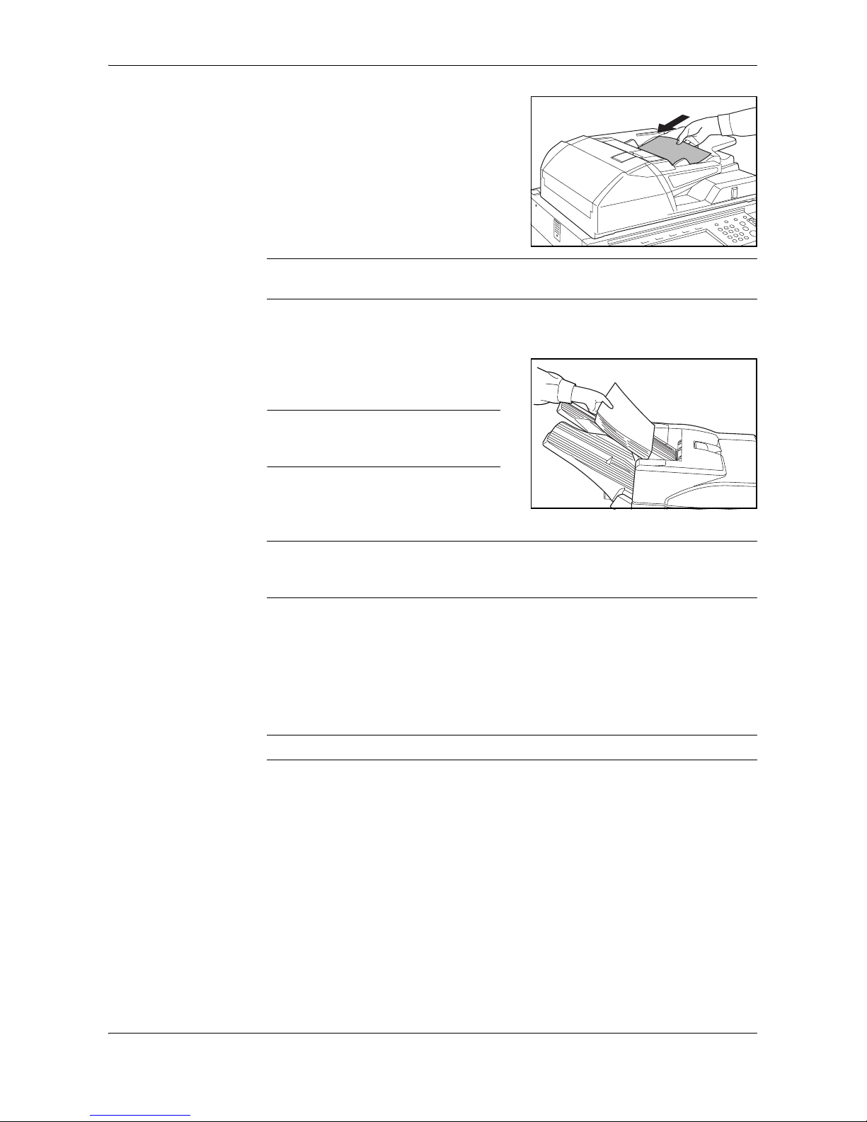
Paper Jam in Tray A
If the illustration shown displays on the
operation panel of your copier, there is a
paper jam in the conveyor section to Tray A.
1
Lift open Tray B.
2
If the jammed paper is visible in the eject slot, pull it out in the direction of ejection
without tearing it.
Page 26

English
1-22 DF-650(B), MT-1(B), BF-1(B), PH-4(A) AND PH-4(C) OPERATION GUIDE
Paper Jam in Tray B
If the illustration shown displays on the
operation panel of your copier, there is a
paper jam in the conveyor section to Tray B.
1
If the jammed paper is visible in the eject
slot, pull it out in the direction of ejection,
without tearing it.
If the jammed paper cannot be easily
removed, proceed to the next step.
2
Open the upper cover and remove the
jammed paper.
3
Close the upper cover.
Page 27
English
DF-650(B), MT-1(B), BF-1(B), PH-4(A) AND PH-4(C) OPERATION GUIDE 1-23
Paper Jam in the Conveyor Section
If the illustration shown displays on the
operation panel of your copier, there is a
paper jam in the conveyor section to the
internal tray.
1
Lift open Tray B.
2
If the jammed paper is visible in the eject slot, pull it out in the direction of ejection,
without tearing it.
If the jammed paper cannot be easily removed, proceed to the next step.
3
Grasp the front cover handle and open the
front cover.
4
Turn internal tray lever G3 clockwise and
pull out the internal tray.
Page 28
English
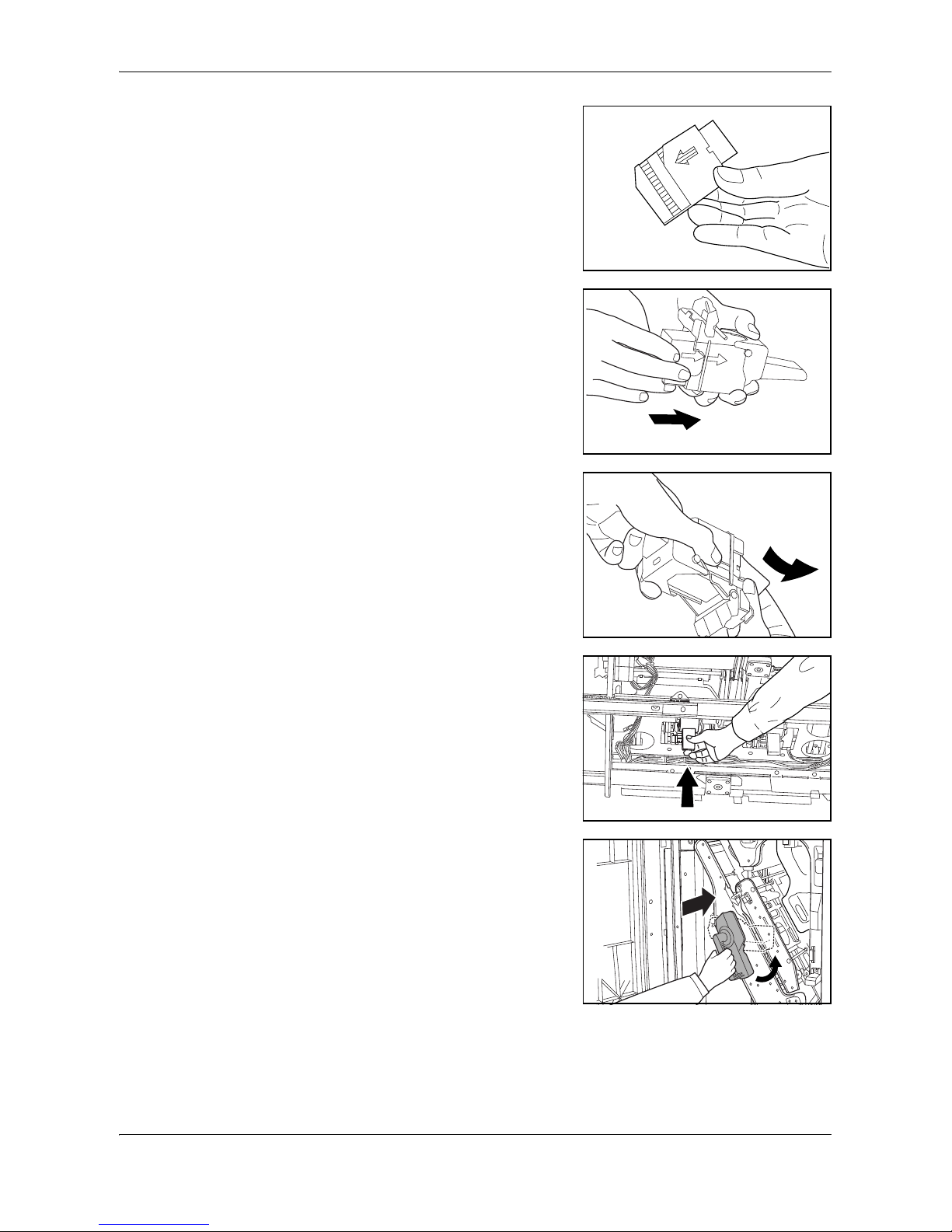
1-24 DF-650(B), MT-1(B), BF-1(B), PH-4(A) AND PH-4(C) OPERATION GUIDE
5
Hold the internal tray release lever (G4) and
open the internal tray.
6
Remove the jammed paper.
7
Hold the internal tray release lever (G4) and
close the internal tray.
8
Push down on the frame to lock the internal
tray in place.
9
Set the internal tray and turn the lever
upright. Close the cover..
Page 29

English
DF-650(B), MT-1(B), BF-1(B), PH-4(A) AND PH-4(C) OPERATION GUIDE 1-25
Paper Jam in the Multi-Job Tray Unit
If a paper jam occurs in the Multi-Job Tray
Unit, follow the procedure below to remove
the jammed paper.
1
If there is any jammed paper in any of the
job trays, remove it without tearing it.
2
If the jammed paper cannot be easily
removed, open the upper cover to the
Document Finisher and remove the jammed
paper.
For further information refer to Paper Jam in
the Coupling Section on page 1-20.
Page 30
English
1-26 DF-650(B), MT-1(B), BF-1(B), PH-4(A) AND PH-4(C) OPERATION GUIDE
Paper Jam in the Center-Folding Unit
Conveyor Section
If the illustration shown displays on the
operation panel of your copier, there is a
paper jam in the conveyor section of the
Center-Folding Unit.
1
Grasp the front cover handle and open the
front cover.
2
Turn the unit release lever (G6), and then
hold the unit release handle (G7) and move
the Center-Folding Unit in the paper
ejection direction.
3
If the jammed paper is visible from under the
internal tray, remove the jammed paper.
4
If paper is jammed inside the internal tray,
remove the jammed paper using the
instructions on page 1-23.
Page 31

English
DF-650(B), MT-1(B), BF-1(B), PH-4(A) AND PH-4(C) OPERATION GUIDE 1-27
5
Hold the conveyor guide lever to open the
conveyor guide and remove the jammed
paper.
6
Lift open the storage cover and remove any
jammed paper.
Lower the storage cover.
7
Close the conveyor guide and push in the
Center-Folding Unit back to its original
position while pressing the Center-Folding
Unit installation button A.
8
Close the front cover.
A
Page 32

English
1-28 DF-650(B), MT-1(B), BF-1(B), PH-4(A) AND PH-4(C) OPERATION GUIDE
Ejection Section
If the illustration shown displays on the
operation panel of your copier, there is a
paper jam in the ejection section of the
Center-Folding Unit.
1
Grasp the front cover handle and open the
front cover.
2
Turn the unit release lever (G6), and then
hold the unit release handle (G7) and move
the Center-Folding Unit in the paper
ejection direction.
3
Hold the conveyor guide lever to open the
conveyor guide and remove the jammed
paper.
4
If the jammed paper cannot be easily
removed, turn the conveyor guide knob to
feed the paper further along for easy
removal.
Remove the paper.
Page 33

English
DF-650(B), MT-1(B), BF-1(B), PH-4(A) AND PH-4(C) OPERATION GUIDE 1-29
5
Close the conveyor guide and push in the
Center-Folding Unit back to its original
position while pressing the Center-Folding
Unit installation button A.
6
Close the front cover.
Curled Output
If the copies ejected are curled, pull out the
pressure roller adjuster (G5) slightly and
turn it so that its projection is set into one of
the five small holes.
1
Grasp the front cover handle and open the
front cover.
2
If ejected copies are curled downward when
using a non-sorting mode, turn the pressure
roller adjuster (G5) in the direction of a
higher number.
3
If ejected copies are curled upward when
using a non-sorting mode, turn the pressure
roller adjuster (G5) in the direction of a lower
number.
A
1
2
3
4
5
1
2
3
4
5
Page 34

English
1-30 DF-650(B), MT-1(B), BF-1(B), PH-4(A) AND PH-4(C) OPERATION GUIDE
4
Once adjustment is complete, close the front cover.
Clearing a Staple Jam
The Document Finisher is equipped with two staple cartridge holders, A and B. The
procedure for clearing a staple jam is the same for both holders.
1
Grasp the front cover handle and open the
front cover.
2
Turn internal tray lever G3 clockwise and
pull out the internal tray.
3
Lift up the staple cartridge holder and pull it
out.
4
Push on tab (A) on the staple cartridge
holder's face plate to open the cover plate
(B).
Page 35

English
DF-650(B), MT-1(B), BF-1(B), PH-4(A) AND PH-4(C) OPERATION GUIDE 1-31
5
Remove any jammed staples from the tip of
the staple cartridge.
6
Lower the cover plate of the staple cartridge
holder into its original position.
7
Re-install the staple cartridge holder.
The staple cartridge holder will click into
place when it is inserted correctly.
8
Set the internal tray and turn the lever
upright. Close the cover.
Page 36

English
1-32 DF-650(B), MT-1(B), BF-1(B), PH-4(A) AND PH-4(C) OPERATION GUIDE
Specifications
NOTE: Specifications are subject to change without notice.
Item Description
Type Floor model
Number of Trays 2
Tray Capacity
(80 g/m
2
weight paper)
Tray A A3, B4, 11 x 17", 8 1/2 x 14" (Legal): 1500 sheets
A4, A4R, B5, B5R, A5R, B6R, A6R, Folio,
8 1/2 x 11" (Letter), 11 x 8 1/2",
5 1/2 x 8 1/2": 3000 sheets
Tray B A3, B4,
A4, A4R
, B5, B5R,
A5R, B6R, A6R, Folio,
11 x 17", 8 1/2 x 14" (Legal), 8 1/2 x 11" (Letter),
11 x 8 1/2", 5 1/2 x 8 1/2": 200 sheets
Dimensions (W x D x H) 796 mm x 640 mm x 1070 mm
31 5/16" x 25 3/16" x 43 1/3"
Weight Approx. 73 Kg (161.6 lbs)
Noise Emission
70 dB(A)
Staple Unit Stapling Capacity A3, B4, 11 x 17", 8 1/2 x 14" (Legal): 30 sheets
A4, A4R, B5, 8 1/2 x 11" (Letter),
11 x 8 1/2": 50 sheets
Storage Capacity
A3, B4, 11 x 17",
8 1/2 x 14" (Legal)
Stapling 2 to 4 sheets: 150 sets
Stapling 5 to 10 sheets: 100 sets
Stapling 11 to 30 sheets: 50 sets
Storage Capacity - A4,
A4R
, 8 1/2 x 11"
(Letter), 11 x 8 1/2",
5 1/2 x 8 1/2"
Stapling 2 to 4 sheets: 150 sets
Stapling 5 to 10 sheets: 100 sets
Stapling 11 to 30 sheets: 50 sets
Stapling 31 to 50 sheets: 3000 sheets
Hole Punch Unit (option) Paper Size A3, B4,
A4, A4R
, B5, B5R,
A5R, Folio
, 11 x 17",
8 1/2 x 14" (Legal) 8 1/2 x 11" (Letter),
11 x 8 1/2", 5 1/2 x 8 1/2"
Page 37

English
DF-650(B), MT-1(B), BF-1(B), PH-4(A) AND PH-4(C) OPERATION GUIDE 1-33
Multi-Job Tray Unit (option) Number of Trays 5
Paper Size A3, B4,
A4, A4R
, B5, B5R,
A5R, B6R, Folio
,
11 x 17", 8 1/2 x 14" (Legal) 8 1/2 x 11" (Letter),
11 x 8 1/2", 5 1/2 x 8 1/2"
Tray Capacity
(80 g/m
2
weight
paper)
A3, B4, 11 x 17", 8 1/2 x 14" (Legal): 100 sheets
A4, A4R
, B5, B5R,
A5R, B6R, Folio
, 8 1/2 x 11"
(Letter), 11 x 8 1/2", 5 1/2 x 8 1/2": 150 sheets
Dimensions 368 mm x 392 mm x 573 mm
14 1/2" x 15 7/16" x 22 9/16"
Weight Approx. 15 kg / 33 lbs
Center-Folding Unit (option) Sizes A3, B4, A4R, 11 x 17", 8 1/2 x 11"
Number of Sheets 1 to 16 (no stapling for 1 sheet)
Maximum Number for
Storage
5 or less copies in a set: 30 sets
6 to 10 copies in a set: 20 sets
11 to 16 copies in a set: 10 sets
Item Description
Page 38

English
1-34 DF-650(B), MT-1(B), BF-1(B), PH-4(A) AND PH-4(C) OPERATION GUIDE
Page 39

DF-650(B), MT-1(B), BF-1(B), PH-4(A) UND PH-4(C) BEDIENUNGSHANDBUCH 2-1
2Deutsch
Sicherheitshinweise
Bitte lesen Sie vor dem Einsatz dieses Geräts das vorliegende Handbuch sorgfältig
durch. Auch nach dem Lesen ist das Handbuch beim Kopierer aufzubewahren, so
dass es immer zur Hand ist.
Informationen zum Kundendienst sind dem Bedienungshandbuch für das Gerät zu
entnehmen.
Die mit Symbolen gekennzeichneten Abschnitte in dieser Bedienungsanleitung und
die markierten Teile des Produkts verweisen auf Sicherheitshinweise, die zum
Schutz des Benutzers, anderer Personen und Objekte im Umfeld des Produkts
dienen.
Die Symbole und ihre Bedeutung werden nachstehend aufgeführt.
Symbole
Die mit dem Symbol gekennzeichneten Abschnitte enthalten Sicherheitshinweise. Spezifische Punkte, auf die verwiesen wird, sind innerhalb dieses Symbols
angeführt.
Die mit dem Symbol gekennzeichneten Abschnitte enthalten Sicherheitshinweise. Spezifische Punkte, auf die verwiesen wird, sind innerhalb dieses Symbols
angeführt.
VORSICHT: Eine unzureichende Beachtung oder falsche Befol-
gung dieser Hinweise bedeutet Verletzungsgefahr für Personen oder
Schäden am Kopiergerät.
ACHTUNG: Eine unzureichende Beachtung oder falsche Befol-
gung dieser Hinweise bedeutet ernsthafte Verletzungs- oder sogar
Todesgefahr.
....
Allgemeiner Gefahrhinweis
....
Warnhinweis auf eine verbotene Handlung
....
Verbotener Ausbau
Page 40

Deutsch
2-2 DF-650(B), MT-1(B), BF-1(B), PH-4(A) UND PH-4(C) BEDIENUNGSHANDBUCH
Ein mit dem Symbol z gekennzeichneter Abschnitt enthält nähere Informationen
über Handlungen, die durchgeführt werden müssen. Spezifische Punkte der durchzuführenden Handlung sind innerhalb dieses Symbols angeführt.
Sollten die Sicherheitshinweise in dieser Bedienungsanleitung unleserlich sein oder
die Bedienungsanleitung gänzlich fehlen, wenden Sie sich bitte an Ihre Kundendienststelle, um diese Hinweise neu zu bestellen (gegen Gebühr).
....
Hinweis auf eine durchzuführende Handlung
....
Netzstecker aus der Steckdose ziehen
....
Das Produkt immer an eine geerdete Steckdose anschließen
Page 41

Deutsch
DF-650(B), MT-1(B), BF-1(B), PH-4(A) UND PH-4(C) BEDIENUNGSHANDBUCH 2-3
WARNSCHILDER
Der Document Finisher ist mit den unten beschriebenen Warnschildern versehen.
BESONDERE VORSICHT ist beim Beseitigen von Papierstaus geboten. Sie könnten sich die Finger im Gerät einklemmen oder verbrennen.
ӛӋӝ!4
ߎߩㇱಽߩౝߪ㜞ߦߥߞߡ߹ߔޕ
Ἣ்ߥߤߩ߅ߘࠇ߇ࠅ߹ߔߩߢޔ⸅
ࠇߥࠃ߁ߦߒߡߊߛߐޕ
оࠪи
чҀѽѢӛӋӝѣѣрщўиѼкџыњуєщи
ӛӋӝ!2
⼊๔㧦ᚻ߇߹ࠆᕟࠇ߇ࠅ߹ߔߩߢޔᯏ߇ᱛߒߡ߆ࠄ↪⚕ࠍขߞߡߐޕ
ӛӋӝ!3
࠻ࠗ㧭ߩߦ‛ࠍ⟎߆ߥߢߊߛߐޕ
WARNSCHILD 2
KEINE Gegenstände unter Fach A stellen.
WARNSCHILD 3
Im Inneren dieses Bereichs liegen
hohe Temperaturen an. Diesen
Bereich KEINESFALLS berühren:
Verbrennungsgefahr!
WARNSCHILD 1
VORSICHT: Um Handverletzungen zu vermeiden, unbedingt warten, bis der Kopierer anhält, ehe
Papier entfernt wird.
HINWEIS: DIESE WARNSCHILDER DÜRFEN
NICHT ENTFERNT WERDEN.
Page 42

Deutsch
2-4 DF-650(B), MT-1(B), BF-1(B), PH-4(A) UND PH-4(C) BEDIENUNGSHANDBUCH
VORSICHTSHINWEISE ZUR AUFSTELLUNG
Umgebung
VORSICHT
Stellen Sie dieses Produkt auf einer horizontalen Fläche auf. Auf unebenen
oder instabilen Flächen kann das Produkt umfallen, was eine
Verletzungsgefahr für Personen darstellt oder Schäden am Produkt bedeutet.
Vermeiden Sie Aufstellungsorte neben Radiatoren, Heizungen oder anderen
Heizgeräten sowie in der Nähe von entflammbaren Gegenständen, um
Brandgefahr auszuschließen.
Andere Vorsichtsmaßnahmen
Die Anforderungen für die Betriebsumgebung sind wie folgend:
• Temperatur: 0°C bis 35°C
• Luftfeuchtigkeit: 10% bis 85%
Beachten Sie, dass Umgebungsbedingungen, wie z.B. Belüftung, sich auf die
Leistung auswirken können.
Folgende Aufstellorte sollten vermieden werden.
• Vermeiden Sie Aufstellungsorte in Fensternähe oder mit direktem
Sonnenlichteinfall.
• Vermeiden Sie vibrationsreiche Aufstellungsorte.
• Vermeiden Sie Aufstellungsorte mit drastischen Temperaturschwankungen.
• Vermeiden Sie Räume, in denen der Kopierer direkter Heiß- oder Kaltluft
ausgesetzt ist.
Handhabung von Plastiktaschen
ACHTUNG
Plastiktaschen, die mit diesem Produkt verwendet werden, sind außerhalb der
Reichweite von Kindern aufzubewahren.
Das Plastik kann sich um Nase und Mund legen und zur Erstickung führen.
VORSICHTSHINWEISE ZUM BETRIEB
Vorsichtshinweise zur Arbeit mit diesem Produkt
ACHTUNG
KEINE Metallgegenstände oder Wasserbehälter (Blumenvasen,
Blumentöpfe, Tassen, usw.) auf das oder in die Nähe dieses Produkts stellen.
Falls Wasser in das Produkt gelangt, besteht die Gefahr eines Brandes oder
Stromschlags.
Das Netzkabel darf nicht beschädigt, geknickt oder repariert werden. Keine
schweren Gegenstände auf das Netzkabel stellen, das Kabel nicht übermäßig
Page 43

Deutsch
DF-650(B), MT-1(B), BF-1(B), PH-4(A) UND PH-4(C) BEDIENUNGSHANDBUCH 2-5
ziehen, unnötig biegen oder sonstwie beschädigen. Ansonsten besteht Brand- oder
Stromschlaggefahr.
Keine Reparaturversuche unternehmen und das Gerät oder seine
Komponenten nicht zerlegen; andernfalls besteht die Gefahr von
Verletzungen, Brand oder Stromschlag.
Falls das Gerät übermäßig heiß läuft, Rauch austritt, ein ungewöhnlicher
Geruch zu verspüren ist oder eine andere außergewöhnliche Situation auftritt,
besteht Brand- oder Stromschlaggefahr. Den Hauptschalter des Kopierers/
Druckers sofort ausschalten und den Netzstecker des Geräts abziehen. Danach den
Kundendienst verständigen.
Falls einmal ein Fremdkörper (z. B. Heftklammer, Wasser oder Flüssigkeit) in
das Gerät geraten ist, den Hauptschalter des Kopierers/Druckers sofort
ausschalten und den Netzstecker des Geräts abziehen. Danach den
Kundendienst verständigen. Wird das Gerät weiter benutzt, ohne
die vorgenannten Maßnahmen zu treffen, besteht Brand- oder Stromschlaggefahr.
Wenden Sie sich IMMER an Ihre Kundendienststelle, um die Wartung und
Reparatur der Innenteile vorzunehmen.
VORSICHT
Aus Sicherheitsgründen den Hauptschalter des Druckers/Kopierers vor dem
Reinigen IMMER ausschalten und den Drucker/Kopierer-Netzstecker von der
Steckdose abziehen.
Achten Sie darauf, die Papierablage NICHT zu berühren, während sich das
Gerät in Betrieb befindet, da Verletzungsgefahr besteht. .
Falls sich Staub im Inneren dieses Produkts ansammelt, besteht Brandgefahr
oder andere Probleme können auftreten.
Wir empfehlen deshalb, daß Sie sich zwecks Reinigung der Innenteile mit
Ihrer Kundendienststelle in Verbindung setzen. Diese Reinigung ist besonders
vor Jahreszeiten mit hoher Luftfeuchtigkeit von großem Nutzen.Lassen Sie
sich bitte von Ihrer Kundendienststelle auch über die Kosten
der Reinigung der Produktinnenteile informieren.
Andere Vorsichtsmaßnahmen
NIEMALS schwere Gegenstände auf dieses Produkt ablegen oder andere Schäden
am Gerät verursachen.
Wenn Sie das Produkt heben oder verschieben wollen, wenden Sie sich an
Ihre Kundendienststelle.
Berühren Sie nicht die elektrischen Teile, wie beispielsweise die Kontakte oder die
Leiterplatten, weil diese Teile durch statische Elektrizität zerstört werden können.
Versuchen Sie NICHT, irgendwelche Handlungen durchzuführen, die nicht in dieser
Bedienungsanleitung erklärt worden sind.
Page 44

Deutsch
2-6 DF-650(B), MT-1(B), BF-1(B), PH-4(A) UND PH-4(C) BEDIENUNGSHANDBUCH
Bezeichnung der Teile
Document Finisher (Hauptgerät) Mittenfaltstation (Extra)
1 Fach A
2 Fach B
3 Vordere Abdeckung
4 Griff der vorderen Abdeckung
5 Obere Abdeckung
6 Internes Fach
7 Griff des internen Fachs (G3)
8 Freigabehebel des internen
Fachs (G4)
9 Andruckwalzenregler (G5)
10 Transportknopf (G1)
11 Hebel für untere Führung des
Kupplungsbereichs (G2)
12 Heftklammermagazinhalterung
A
13 Heftklammermagazinhalterung
B
14 Hebel für obere Führung des
Kupplungsbereichs
18 Freigabehebel (G6)
19 Freigabegriff (G7)
20 Entriegelungshebel der
Mittenfaltstation
21 Installationstasten der
Mittenfaltstation
22 Hebel der Transportführung
23 Speicherabdeckung
Lochstanzer (Extra)
15 Lochstanzer (Hauptgerät)
16 Einstellrad des Lochstanzers
17 Lochungsabfallbehälter
Multi Tray (Extra)
24 Auftragsfächer 1 - 5
910 11
18
8
20
19
21
23
24
17
12
16
15
13 14
25
5
21
3
4
7
6
22
Page 45

Deutsch
DF-650(B), MT-1(B), BF-1(B), PH-4(A) UND PH-4(C) BEDIENUNGSHANDBUCH 2-7
Betriebsarten
"Sortieren: EIN"-Modus
Sortiert Kopien mehrerer Originale in identischen Sätzen. Beispiel: A,B,C,D A,B,C,D
A,B,C,D.
Folgende Papierformate werden im
Sortieren:EIN-Modus unterstützt:
• A3, B4, A4, A4R, B5, 11 x 17 Zoll,
8 1/2 x 14 Zoll (Legal), 8 1/2 x 11 Zoll
(Letter) und 11 x 8 1/2 Zoll.
1
Am Bedienfeld des Kopierers Sortieren: Ein wählen.
2
Originale in den automatischen Vorlageneinzug legen oder einzeln über das Vorlagenglas zuführen.
HINWEIS: Siehe auch die tech-
nischen Daten des automatischen Vorlageneinzugs und des Vorlagenglases
im Bedienungshandbuch zu Ihrem
Kopierer.
3
Gegebenenfalls weitere Funktionen auswählen und Start betätigen.
4
Die Kopien werden in das vereinbarte Fach
ausgegeben.
Bei Auswahl von Fach A kann man für jeden
Kopiensatz einen Versatz zum jeweils vorherigen Satz vereinbaren. Siehe hierzu
auch das Bedienungshandbuch zu Ihrem
Kopierer.
D
C
B
A
D
C
B
A
D
C
B
A
D
C
B
A
Page 46

Deutsch
2-8 DF-650(B), MT-1(B), BF-1(B), PH-4(A) UND PH-4(C) BEDIENUNGSHANDBUCH
Wenn die Fächer A und B an ihre Kapazitätsgrenzen stoßen, erscheint eine
entsprechende Meldung. In diesem Fall müssen beide Fächer geleert werden, um
weitermachen zu können.
HINWEIS: Wie viele Kopien maximal in Behälter A und B abgelegt werden kön-
nen, hängt vom jeweiligen Kopienformat ab. Weitere Informationen hierzu siehe
Kapazität auf Seite 2-32.
5
Bei Fertigstellung des Auftrags die Kopien entnehmen.
"Sortieren: AUS"-Modus
Fasst die Kopien für jedes Original zu einem
separaten Stapel zusammen. Beispiel:
A,A,A B,B,B C,C,C.
Folgende Papierformate werden im Sor-
tieren:AUS-Modus unterstützt:
• A3, B4, A4, A4R, B5, 11 x 17 Zoll,
8 1/2 x 14 Zoll (Legal), 8 1/2 x 11 Zoll
(Letter) und 11 x 8 1/2 Zoll.
1
Am Bedienfeld des Kopierers Sortieren: Aus wählen.
2
Originale in den automatischen Vorlageneinzug legen oder einzeln über das Vorlagenglas zuführen.
HINWEIS: Siehe auch die tech-
nischen Daten des automatischen Vorlageneinzugs und des Vorlagenglases
im Bedienungshandbuch zu Ihrem
Kopierer.
3
Gegebenenfalls weitere Funktionen auswählen und Start betätigen.
C
B
A
C
C
C
B
B
B
A
A
A
Page 47

Deutsch
DF-650(B), MT-1(B), BF-1(B), PH-4(A) UND PH-4(C) BEDIENUNGSHANDBUCH 2-9
4
Die Kopien werden in das vereinbarte Fach
ausgegeben.
Bei Auswahl von Fach A kann man für jeden
Stapel einen Versatz zum jeweils vorherigen Stapel vereinbaren. Weitere Informationen hierzu finden Sie im Bedienungs-
handbuch zu Ihrem Kopierer.
Wenn die Fächer A und B an ihre Kapazitätsgrenzen stoßen, erscheint eine
entsprechende Meldung. In diesem Fall müssen beide Fächer geleert werden, um
weitermachen zu können.
HINWEIS: Wie viele Kopien maximal in Behälter A und B abgelegt werden kön-
nen, hängt vom jeweiligen Kopienformat ab. Weitere Informationen hierzu siehe
Kapazität auf Seite 2-32. Übersteigt die Anzahl der Kopien, die gleichzeitig im
unsortierten Betrieb gemacht werden sollen, die Maximalkapazität von Fach B
(200 Blatt), werden alle nachfolgenden Kopien in Fach A ausgegeben.
5
Bei Fertigstellung des Auftrags die Kopien entnehmen.
"Heften"-Modus
Alle Kopiensätze werden sortiert und
geheftet.
Folgende Heftoptionen werden unterstützt:
• Einzelheftung, oben links
• Einzelheftung, oben rechts
• Doppelheftung
HINWEIS: Siehe auch die technische Daten der Heftfunktion:Hefter auf Seite 2-32.
1
Am Bedienfeld des Kopierers Sortieren: Ein wählen.
2
Die gewünschte Hefteinstellung auswählen.
D
C
B
A
D
C
B
A
D
C
B
A
D
C
B
A
A
A
A A
A AA
A
AA
A
A
A
A
Page 48

Deutsch
2-10 DF-650(B), MT-1(B), BF-1(B), PH-4(A) UND PH-4(C) BEDIENUNGSHANDBUCH
3
Originale in den automatischen Vorlageneinzug legen oder einzeln über das Vorlagenglas zuführen.
HINWEIS: Siehe auch die tech-
nischen Daten des automatischen Vorlageneinzugs und des Vorlagenglases
im Bedienungshandbuch zu Ihrem
Kopierer.
4
Gegebenenfalls weitere Funktionen auswählen und Start betätigen.
5
Die Kopien werden geheftet und in Fach A
ausgegeben (Schriftbild nach unten).
Wenn Fach A an seine Kapazitätsgrenze
stößt, erscheint eine entsprechende Meldung. In diesem Fall muss Fach A geleert
werden, um weitermachen zu können.
HINWEIS: Wie viele Kopien maximal in Behälter A abgelegt werden können, hängt
vom jeweiligen Kopienformat ab. Weitere Informationen hierzu siehe Kapazität auf
Seite 2-32.
6
Bei Fertigstellung des Auftrags die Kopien entnehmen.
"Nicht sortieren"-Modus
Diesen Modus verwenden, wenn keine Sortierung oder Gruppierung erforderlich ist.
Für das Kopieren auf Overheadfolien oder
anderen Sondermaterialien bzw. Papier IMMER den unsortierten Betrieb aktivieren.
C
B
D
A
E
C
B
D
A
E
Page 49

Deutsch
DF-650(B), MT-1(B), BF-1(B), PH-4(A) UND PH-4(C) BEDIENUNGSHANDBUCH 2-11
"Broschüren-Finisher"-Modus
In dieser Betriebsart werden die Kopien in
der Papiermitte an zwei Stellen geheftet.
Folgende Papierformate werden im
Broschüren-Finisher-Modus unterstützt:
• A3, B4, A4R, 11 x 17", 8 1/2 x 14 Zoll
(Legal) und 11 x 8 1/2 Zoll.
Heftkapazität: 2 bis 16 Blätter gleichzeitig.
Für die automatische Faltung wird eine
optionale Mittenfaltstation benötigt.
Die Funktion Booklet Copy (Broschürenkopie) ermöglicht die automatische Erstellung von Broschüren, die sich direkt heften
und falzen lassen. Siehe hierzu auch das
Bedienungshandbuch zu Ihrem Kopierer.
1
Am Bedienfeld des Kopierers Broschüren-Finisher (Booklet Stitching) wählen.
Siehe hierzu auch das Bedienungshandbuch zu Ihrem Kopierer.
2
Originale in den automatischen Vorlageneinzug legen oder einzeln über das Vorlagenglas zuführen.
HINWEIS: Siehe auch die tech-
nischen Daten des automatischen Vorlageneinzugs und des Vorlagenglases
im Bedienungshandbuch zu Ihrem
Kopierer.
Es können maximal 16 Blätter gleichzeitig geheftet werden. In dieser Betriebsart
werden bis zu 64 Originale unterstützt.
3
Gegebenenfalls weitere Funktionen
auswählen und Start betätigen.
Bei Einsatz des Vorlagenglases erscheint
nach dem Scannen jeder Vorlage eine Meldung mit der Frage, ob ein weiteres Vorlage
eingelesen oder der Kopiervorgang gestartet werden soll.
HINWEIS: Siehe hierzu auch das Bedienungshandbuch zu Ihrem Kopierer.
Page 50

Deutsch
2-12 DF-650(B), MT-1(B), BF-1(B), PH-4(A) UND PH-4(C) BEDIENUNGSHANDBUCH
4
Die Kopien werden automatisch geheftet
und auf der Speicherabdeckung abgelegt.
Bei Erreichen der Kapazitätsgrenze erscheint eine entsprechende Meldung. In
diesem Fall müssen alle Kopien entfernt
werden, um weitermachen zu können.
HINWEIS: Weitere Informationen hierzu siehe Mittenfaltstation (Extra) auf Seite
2-33.
5
Bei Fertigstellung des Auftrags die Kopien
aus der Speicherabdeckung nehmen.
"Lochen"-Modus
Der Lochstanzer ist eine optionale Geräteeinheit. In dieser Betriebsart werden automatisch gelochte Kopien erstellt.
Folgende Papierformate werden unterstützt:
• Zweifachlochung: A3, B4, A4, A4R,
B5, B5R, A5R, Folio, 8 1/2 x 14 Zoll
(Legal), 8 1/2 x 11 Zoll (Letter) und
5 1/2 x 8 1/2 Zoll
• Dreifachlochung: 11 x 17 Zoll and 11 x 8 1/2 Zoll
• Vierfachlochung: A3 und A4
Der Lochen-Modus kann in Verbindung mit folgenden Betriebsarten eingesetzt wer-
den: Sortieren: EIN, Heften und Sortieren: AUS. Das Papiergewicht muss zwischen
45 g/m
2
und 200 g/m2 liegen.
HINWEIS: B5R ist nur wählbar, wenn Kopien in Fach A ausgegeben werden. Im
Sortier- und im Heftbetrieb sind B5R und Folio nicht verfügbar.
1
Am Bedienfeld des Kopierers Lochen (Hole Punch) wählen.
HINWEIS: Siehe hierzu auch das Bedienungshandbuch zu Ihrem Kopierer.
Page 51

Deutsch
DF-650(B), MT-1(B), BF-1(B), PH-4(A) UND PH-4(C) BEDIENUNGSHANDBUCH 2-13
2
Originale in den automatischen Vorlageneinzug legen oder einzeln über das Vorlagenglas zuführen.
Sicherstellen, dass die Ausrichtung der
Originale dem gewählten Lochen-Modus
des Kopierers entspricht.
HINWEIS: Siehe auch die technischen Daten des automatischen Vorlageneinzugs
und des Vorlagenglases im Bedienungshandbuch zu Ihrem Kopierer.
3
Gegebenenfalls weitere Funktionen auswählen und Start betätigen.
4
Die Kopien werden automatisch gelocht
und in Fach B ausgegeben.
HINWEIS: Da jede Kopie einzeln
gelocht wird, kann die Lochposition von
Blatt zu Blatt variieren.
Bei Fertigstellung des Auftrags alle Kopien
entnehmen.
HINWEIS: Bei Erreichen der Kapazitätsgrenze von Fach B werden alle nachfol-
genden Kopien in Fach A ausgegeben. Ist Fach A nicht aktiv, wenn Fach B voll ist,
erscheint eine entsprechende Meldung. Alle Kopien entfernen, um weitermachen
zu können.
Unterbrechungsmodus
Im Unterbrechungsmodus werden die Kopien für einen unterbrochenen Auftrag normalerweise in das derzeit nicht genutzte Endbearbeitungsfach ausgegeben. Bei Bedarf kann jedoch über das Bedienfeld ein anderes Fach vereinbart werden.
HINWEIS: Siehe hierzu auch das Bedienungshandbuch zu Ihrem Kopierer.
Page 52

Deutsch
2-14 DF-650(B), MT-1(B), BF-1(B), PH-4(A) UND PH-4(C) BEDIENUNGSHANDBUCH
Multi Tray
Der Multi Tray ist eine optionale Geräteeinheit. Die Druck- oder Kopierausgabe kann
in ein vereinbartes Multi Tray-Fach ausgegeben werden.
Diese Option ist besonders praktisch, wenn
der Kopierer von mehreren Benutzern als
Drucker genutzt wird. Die gedruckten Dokumente werden in diesem Fall in das
gewählte Auftragsfach der einzelnen Benutzer ausgegeben.
Folgende Papierformate werden unterstützt:
• Normalpapier (80 g/m
2
): von A3 bis B6R oder Folio, 11 x 17 Zoll und
8 1/2 x 11 Zoll
• Recycling-Papier (80 g/m
2
): A3, A4, A4R, 11 x 17 Zoll, 11 x 8 1/2 Zoll und
8 1/2 x 11 Zoll
• Farbiges Papier (80 g/m
2
): A4, A4R, 8 1/2 x 11 Zoll und 11 x 8 1/2 Zoll
HINWEIS: Wie viele Kopien maximal in jedem Auftragsfach abgelegt werden kön-
nen, hängt vom jeweiligen Kopienformat ab. Weitere Informationen hierzu siehe
auf Seite 2-33.
1
Die Namen der einzelnen AuftragsfachBenutzer auf den mitgelieferten Etiketten
notieren.
2
Die Etiketten wie in der Abbildung gezeigt
an den Auftragsfächern befestigen.
Die Fächer, an denen Etiketten angebracht
werden sollten, sind von oben nach unten
mit 1, 2, 3, 4 und 5 durchnummeriert.
3
In der Computeranwendung anschließend eine Auftragsfach-Nummer zwischen 1
und 5 wählen.
4
Das Papierformat, die zu druckende(n) Seite(n) sowie die gewünschte Anzahl Ausdrucke vereinbaren.
Page 53

Deutsch
DF-650(B), MT-1(B), BF-1(B), PH-4(A) UND PH-4(C) BEDIENUNGSHANDBUCH 2-15
5
Druckauftrag ausführen.
Die Drucke werden in das gewählte Auftragsfach ausgegeben.
6
Bei Fertigstellung des Auftrags alle Drucke aus dem Auftragsfach nehmen.
HINWEIS: Informationen zum Einsatz des Kopierers in Verbindung mit einem bes-
timmten Fach enthält das Bedienungshandbuch zu Ihrem Kopierer.
Page 54

Deutsch
2-16 DF-650(B), MT-1(B), BF-1(B), PH-4(A) UND PH-4(C) BEDIENUNGSHANDBUCH
Wartung
Heftklammern nachfüllen
Der Document Finisher verfügt über zwei Halterungen für Heftklammermagazine
(A und B). Die Vorgehensweise für das Nachfüllen von Heftklammern ist bei beiden
Halterungen gleich.
Falls eine Meldung erscheint, die darauf hinweist, dass keine Heftklammern mehr
verfügbar sind, müssen Sie ein oder beide Heftklammermagazine auffüllen.
HINWEIS: Wenn sich im Hefter keine Heftklammern mehr befinden, sollten Sie
sich an den Kundendienst oder die zuständige Verkaufsstelle wenden.
1
Den Griff der vorderen Abdeckung fassen
und die vordere Abdeckung öffnen.
2
Hebel (G3) der inneren Ablage nach rechts
drehen und innere Ablage herausziehen.
3
Die Heftklammermagazinhalterung anheben und herausziehen.
4
Das leere Heftklammermagazin aus der
Magazinhalterung nehmen.
Page 55

Deutsch
DF-650(B), MT-1(B), BF-1(B), PH-4(A) UND PH-4(C) BEDIENUNGSHANDBUCH 2-17
5
Das neue Heftklammermagazin aus der
zugehörigen Box nehmen.
6
Die Heftklammermagazinhalterung in eine
Hand nehmen und das neue Heftklammermagazin in die andere; dann das Magazin in
die Halterung einsetzen.
Sicherstellen, dass das Magazin richtig
herum eingesetzt wird. Beide Pfeile müssen
in dieselbe Richtung weisen.
7
Sicherstellen, dass sich das neue Heftklammermagazin vollständig in der Magazinhalterung befindet; dann den Papierstreifen
abziehen.
8
Die Heftklammermagazinhalterung wieder
einsetzen.
Die Heftklammermagazinhalterung rastet
spürbar ein, wenn sie korrekt eingesetzt
worden ist.
9
Innere Ablage einsetzen und Hebel senkrecht stellen. Abdeckung schliessen..
Lochungsabfallbehälter leeren
Wenn die Meldung "Lochungsabfallbehälter leeren" erscheint, müssen die
Papierschnitzel aus dem Lochungsabfallbehälter entfernt werden.
Page 56

Deutsch
2-18 DF-650(B), MT-1(B), BF-1(B), PH-4(A) UND PH-4(C) BEDIENUNGSHANDBUCH
Den Kopierer hierbei eingeschaltet lassen (Betriebsschalter in der Position EIN ( | )).
1
Den Griff der vorderen Abdeckung fassen
und die vordere Abdeckung öffnen.
2
Den Griff des Lochungsabfallbehälters
fassen und den Behälter aus dem Docu-
ment Finisher herausnehmen.
3
Die Lochungsabfälle ordnungsgemäß
entsorgen.
4
Den Lochungsabfallbehälter wieder einsetzen. Den Behälter hierbei an den
Führungen im Document Finisher ausrichten.
5
Die Vordere Abdeckung schließen.
Page 57

Deutsch
DF-650(B), MT-1(B), BF-1(B), PH-4(A) UND PH-4(C) BEDIENUNGSHANDBUCH 2-19
Störungsbeseitigung
Allgemeines
Sind die ausgeworfenen Kopien nicht flach
oder ungleichmäßig gestapelt, das Papier in
der Kassette umdrehen und die Kassette
wieder einsetzen.
Sind die Kopien übermäßig gewellt, siehe
Gewellte Ausgabe auf Seite 2-29.
Bei einem Papierstau prüfen, ob die seitliche Führung in der Kassette für das verwendete Papierformat eingestellt ist.
Beseitigung von Papierstaus
Das Gerät eingeschaltet lassen – Betriebsschalter in Position EIN ( | ) – und Papierstaus wie nachfolgend beschrieben
beseitigen.
Die Abdeckung des Kopierers öffnen und
den Fixierknopf (A1) mindestens 20-mal
nach links drehen, bevor Sie mit der Beseitigung des Papierstaus beginnen.
Nach der Staubeseitigung wechselt das Bedienfeld des Kopierers wieder in den Zustand vor Staubeginn – mit allen zugehörigen Einstellungen.
Page 58

Deutsch
2-20 DF-650(B), MT-1(B), BF-1(B), PH-4(A) UND PH-4(C) BEDIENUNGSHANDBUCH
Papierstau im Kupplungsbereich
Erscheint am Bedienfeld des Kopierers das
hier gezeigte Bild, liegt ein Papierstau im
Kupplungsbereich zwischen Document
Finisher und Kopierer vor.
1
Die obere Abdeckung öffnen und das
gestaute Papier entfernen.
Wenn sich das gestaute Papier nicht ohne
Weiteres entfernen lässt, mit dem nächsten
Schritt fortfahren.
Ist der optionale Lochstanzer installiert,
müssen Sie sicherstellen, dass sich der
Pfeil am Einstellrad in etwa zwischen den
Aussparungen an der Basis der Lochstanz-
einheit befindet.
2
Den Griff der vorderen Abdeckung fassen
und die vordere Abdeckung öffnen.
3
Das Papier durch Drehen des Transportknopfs (G1) so weit vorbewegen, bis es sich
problemlos entfernen lässt.
Papier entfernen.
Wenn sich das gestaute Papier nicht ohne
Weiteres entfernen lässt, mit dem nächsten
Schritt fortfahren.
Page 59

Deutsch
DF-650(B), MT-1(B), BF-1(B), PH-4(A) UND PH-4(C) BEDIENUNGSHANDBUCH 2-21
4
Den Hebel für die obere Führung des Kupplungsbereichs anheben und das gestaute
Papier entfernen.
Den Hebel für die obere Führung sowie die
obere Abdeckung schließen.
5
Den Hebel für untere Führung des Kupplungsbereichs (G2) fassen und öffnen.
Die untere Führung schließen.
6
Die vordere Abdeckung schließen.
Papierstau in Fach A
Erscheint am Bedienfeld des Kopierers das
hier gezeigte Bild, liegt ein Papierstau im
Transportbereich von Fach A vor.
1
Fach B durch Anheben öffnen.
2
Ist das gestaute Papier am Auswurfschlitz zu sehen, das Papier in Auswurfrichtung
herausziehen, ohne es zu zerreißen.
Page 60

Deutsch
2-22 DF-650(B), MT-1(B), BF-1(B), PH-4(A) UND PH-4(C) BEDIENUNGSHANDBUCH
Papierstau in Fach B
Erscheint am Bedienfeld des Kopierers das
hier gezeigte Bild, liegt ein Papierstau im
Transportbereich von Fach B vor.
1
Ist das gestaute Papier am Auswurfschlitz
zu sehen, das Papier in Auswurfrichtung
herausziehen, ohne es zu zerreißen.
Wenn sich das gestaute Papier nicht ohne
Weiteres entfernen lässt, mit dem nächsten
Schritt fortfahren.
2
Die obere Abdeckung öffnen und das
gestaute Papier entfernen.
3
Die obere Abdeckung schließen.
Page 61

Deutsch
DF-650(B), MT-1(B), BF-1(B), PH-4(A) UND PH-4(C) BEDIENUNGSHANDBUCH 2-23
Papierstau im Transportbereich
Erscheint am Bedienfeld des Kopierers das
hier gezeigte Bild, liegt ein Papierstau im
Transportbereich zum internen Fach vor.
1
Fach B durch Anheben öffnen.
2
Ist das gestaute Papier am Auswurfschlitz zu sehen, das Papier in Auswurfrichtung
herausziehen, ohne es zu zerreißen.
Wenn sich das gestaute Papier nicht ohne Weiteres entfernen lässt, mit dem
nächsten Schritt fortfahren.
3
Den Griff der vorderen Abdeckung fassen
und die vordere Abdeckung öffnen.
4
Hebel (G3) der inneren Ablage nach rechts
drehen und innere Ablage herausziehen.
Page 62

Deutsch
2-24 DF-650(B), MT-1(B), BF-1(B), PH-4(A) UND PH-4(C) BEDIENUNGSHANDBUCH
5
Den Freigabehebel des internen Fachs
(G4) fassen und das interne Fach öffnen.
6
Das gestaute Papier entfernen.
7
Den Freigabehebel des internen Fachs
(G4) fassen und das interne Fach
schließen.
8
Auf den Rahmen drücken, bis das interne
Fach ordnungsgemäß einrastet.
9
Innere Ablage einsetzen und Hebel senkrecht stellen. Abdeckung schliessen..
Page 63

Deutsch
DF-650(B), MT-1(B), BF-1(B), PH-4(A) UND PH-4(C) BEDIENUNGSHANDBUCH 2-25
Papierstau im Multi Tray
Papierstaus im Multi Tray werden wie folgt
beseitigt:
1
Falls sich gestautes Papier in einem der
Auftragsfächer befindet, das Papier entfernen, ohne es zu zerreißen.
2
Lässt sich das gestaute Papier nicht ohne
Weiteres entfernen, die obere Abdeckung
des Document Finishers öffnen und das
Papier dann entfernen.
Weitere Informationen hierzu siehe Papier-
stau im Kupplungsbereich auf Seite 2-20.
Page 64

Deutsch
2-26 DF-650(B), MT-1(B), BF-1(B), PH-4(A) UND PH-4(C) BEDIENUNGSHANDBUCH
Papierstau in der Mittenfaltstation
Transportbereich
Erscheint am Bedienfeld des Kopierers das
hier gezeigte Bild, liegt ein Papierstau im
Transportbereich der Mittenfaltstation vor.
1
Den Griff der vorderen Abdeckung fassen
und die vordere Abdeckung öffnen.
2
Den Freigabehebel der Einheit (G6) drehen;
anschließend den Freigabegriff dieser Einheit (G7) fassen und die Mittenfaltstation in
Richtung des Papierauswurfs bewegen.
3
Ist das gestaute Papier unter dem internen
Fach zu sehen, das Papier entfernen.
4
Hat sich das Papier im Inneren des internen
Fachs gestaut, das Papier wie auf Seite
2-23 beschrieben entfernen.
Page 65

Deutsch
DF-650(B), MT-1(B), BF-1(B), PH-4(A) UND PH-4(C) BEDIENUNGSHANDBUCH 2-27
5
Den Hebel der Transportführung fassen
und die Führung öffnen; anschließend das
gestaute Papier entfernen.
6
Die Speicherabdeckung durch Anheben
öffnen und das gestaute Papier entfernen.
Speicherabdeckung absenken.
7
Die Transportführung schließen. Die Mittenfaltstation wieder in die Ausgangsposition
bringen; hierbei gleichzeitig die
Installationstaste A der Station betätigen.
8
Die vordere Abdeckung schließen.
A
Page 66

Deutsch
2-28 DF-650(B), MT-1(B), BF-1(B), PH-4(A) UND PH-4(C) BEDIENUNGSHANDBUCH
Ausgabebereich
Erscheint am Bedienfeld des Kopierers das
hier gezeigte Bild, liegt ein Papierstau im
Ausgabebereich der Mittenfaltstation vor.
1
Den Griff der vorderen Abdeckung fassen
und die vordere Abdeckung öffnen.
2
Den Freigabehebel der Einheit (G6) drehen;
anschließend den Freigabegriff dieser Einheit (G7) fassen und die Mittenfaltstation in
Richtung des Papierauswurfs bewegen.
3
Den Hebel der Transportführung fassen
und die Führung öffnen; anschließend das
gestaute Papier entfernen.
4
Lässt sich das gestaute Papier nicht ohne
Weiteres entfernen, den Knopf der Transportführung drehen und das Papier so weit
vorbewegen, bis es sich problemlos entfernen lässt.
Papier entfernen.
Page 67

Deutsch
DF-650(B), MT-1(B), BF-1(B), PH-4(A) UND PH-4(C) BEDIENUNGSHANDBUCH 2-29
5
Die Transportführung schließen und die
Mittenfaltstation wieder in die Ausgangsposition bringen; hierbei gleichzeitig die
Installationstaste der Mittenfaltstation
betätigen.
6
Die vordere Abdeckung schließen.
Gewellte Ausgabe
Falls übermäßig gewellte Kopien ausgegeben werden, den Andruckwalzenregler (G5)
leicht herausziehen und so drehen, dass
der Vorsprung am Regler in eine der fünf
kleinen Öffnungen greift.
1
Den Griff der vorderen Abdeckung fassen
und die vordere Abdeckung öffnen.
2
Sind die Kopien bei Ausgabe im unsortierten Betrieb nach unten gewellt, den Andruckwalzenregler (G5) so drehen, dass ein
höherer Wert eingestellt wird.
3
Sind die Kopien bei Ausgabe im unsortierten Betrieb nach oben gewellt, den Andruckwalzenregler (G5) so drehen, dass ein
niedrigerer Wert eingestellt wird.
A
1
2
3
4
5
1
2
3
4
5
Page 68

Deutsch
2-30 DF-650(B), MT-1(B), BF-1(B), PH-4(A) UND PH-4(C) BEDIENUNGSHANDBUCH
4
Die vordere Abdeckung nach dieser Anpassung wieder schließen.
Heftklammerstau beseitigen
Der Document Finisher verfügt über zwei Halterungen für Heftklammermagazinhalterungen (A und B). Die Vorgehensweise für das Beseitigen von Heftklammerstaus ist bei beiden Halterungen gleich.
1
Den Griff der vorderen Abdeckung fassen
und die vordere Abdeckung öffnen.
2
Hebel (G3) der inneren Ablage nach rechts
drehen und innere Ablage herausziehen.
3
Die Heftklammermagazinhalterung anheben und herausziehen.
4
Auf den Haken (A) an der Frontplatte der
Heftklammermagazinhalterungen drücken,
um die Abdeckplatte (B) zu öffnen.
Page 69

Deutsch
DF-650(B), MT-1(B), BF-1(B), PH-4(A) UND PH-4(C) BEDIENUNGSHANDBUCH 2-31
5
Gegebenenfalls an der Spitze des Heftklammermagazins gestaute Heftklammern
entfernen.
6
Die Abdeckplatte der Heftklammermagazinhalterung wieder in die Ausgangsposition
bringen.
7
Die Heftklammermagazinhalterung wieder
einsetzen.
Die Heftklammermagazinhalterung rastet
spürbar ein, wenn sie korrekt eingesetzt
wird.
8
Innere Ablage einsetzen und Hebel senkrecht stellen. Abdeckung schliessen.
Page 70

Deutsch
2-32 DF-650(B), MT-1(B), BF-1(B), PH-4(A) UND PH-4(C) BEDIENUNGSHANDBUCH
Technische Daten
HINWEIS: Änderungen an den technischen Daten sind jederzeit vorbehalten.
Position Beschreibung
Typ Standmodell
Fächer 2
Kapazität
(Papiergewicht: 80 g/m
2
)
Fach A A3, B4, 11 x 17 Zoll, 8 1/2 x 14 Zoll
(Legal): 1500 Blatt
A4, A4R, B5, B5R, A5R, B6R, A6R, Folio,
8 1/2 x 11 Zoll (Letter), 11 x 8 1/2 Zoll,
5 1/2 x 8 1/2 Zoll: 3000 Blatt
Fach B A3, B4, A4, A4R, B5, B5R, A5R, B6R, A6R, Folio,
11 x 17 Zoll, 8 1/2 x 14 Zoll (Legal), 8 1/2 x 11 Zoll
(Letter), 11 x 8 1/2 Zoll, 5 1/2 x 8 1/2 Zoll: 200
Blatt
Abmessungen (B) x (T) x (H) 796 mm x 640 mm x 1070 mm
(31 5/16 Zoll x 25 3/16 Zoll x 43 1/3 Zoll)
Gewicht Ca. 73 Kg
Geräuschentwicklung
70 dB(A)
Hefter Heftkapazität A3, B4, 11 x 17 Zoll, 8 1/2 x 14 Zoll
(Legal): 30 Blatt
A4, A4R, B5, 8 1/2 x 11 Zoll (Letter),
11 x 8 1/2 Zoll: 50 Blatt
Speicherkapazität
A3, B4, 11 x 17 Zoll, 8
1/2 x 14 Zoll (Legal)
Heftsätze aus 2 - 4 Blättern: 150 Sätze
Heftsätze aus 5 - 10 Blättern: 100 Sätze
Heftsätze aus 11 - 30 Blättern: 50 Sätze
Speicherkapazität
-
A4, A4R
, 8 1/2 x 11
Zoll (Letter),
11 x 8 1/2 Zoll,
5 1/2 x 8 1/2 Zoll
Heftsätze aus 2 - 4 Blättern: 150 Sätze
Heftsätze aus 5 - 10 Blättern: 100 Sätze
Heftsätze aus 11 - 30 Blättern: 50 Sätze
Heftsätze aus 31 - 50 Blättern: 3000 Blätter
Lochstanzer (Extra) Papierformat A3, B4,
A4, A4R
, B5, B5R,
A5R, Folio
, 11 x 17
Zoll, 8 1/2 x 14 Zoll (Legal) 8 1/2 x 11 Zoll (Letter),
11 x 8 1/2 Zoll, 5 1/2 x 8 1/2 Zoll
Page 71

Deutsch
DF-650(B), MT-1(B), BF-1(B), PH-4(A) UND PH-4(C) BEDIENUNGSHANDBUCH 2-33
Multifinisher (Extra)
Fächer 5
Papierformat A3, B4,
A4, A4R
, B5, B5R,
A5R, B6R, Folio
,
11 x 17 Zoll, 8 1/2 x 14 Zoll" (Legal),
8 1/2 x 11 Zoll (Letter), 11 x 8 1/2 Zoll,
5 1/2 x 8 1/2 Zoll
Kapazität (Papiergewicht: 80 g/m
2
)
A3, B4, 11 x 17 Zoll, 8 1/2 x 14 Zoll
(Legal): 100 Blatt
A4, A4R, B5, B5R, A5R, B6R, Folio,
8 1/2 x 11 Zoll (Letter), 11 x 8 1/2 Zoll,
5 1/2 x 8 1/2 Zoll: 150 Blatt
Abmessungen 368 mm x 392 mm x 573 mm
(14 1/2 Zoll x 15 7/16 Zoll x 22 9/16 Zoll)
Gewicht Ca. 15 kg
Mittenfaltstation (Extra) Formate A3, B4, A4R, 11 x 17 Zoll, 8 1/2 x 11 Zoll
Anzahl Blätter 1 bis 16 (keine Heftung bei 1 Blatt)
Max. Kapazität 5 oder weniger Kopien pro Satz: 30 Sätze
6 bis 10 Kopien pro Satz: 20 Sätze
11 bis 16 Kopien pro Satz: 10 Sätze
Position Beschreibung
Page 72

Deutsch
2-34 DF-650(B), MT-1(B), BF-1(B), PH-4(A) UND PH-4(C) BEDIENUNGSHANDBUCH
Page 73

DF-650(B), MT-1(B), BF-1(B), PH-4(A) Y PH-4(C) GUÍA DE USO 3-1
3 Español
Información de seguridad
Lea esta Guía de uso antes de utilizar este producto. Después de leerla, guárdela
cerca de la copiadora/impresora para facilitar las consultas.
Consulte la Guía de uso de la copiadora/impresora si desea información acerca del
técnico de servicio de su producto.
Las secciones de este manual de instrucciones y las partes de este producto
marcados con símbolos representan advertencias de seguridad destinadas a
proteger al usuario, otros individuos y los objetos circundantes, y a garantizar una
utilización correcta y segura de este producto.
A continuación se indican los símbolos y sus significados.
Símbolos
El símbolo indica que la sección correspondiente contiene avisos de seguridad.
Los puntos específicos de atención se indican dentro del símbolo.
El símbolo indica que dicha sección incluye información relativa a acciones
prohibidas. En el interior del símbolo se indican puntos específicos de dicha acción
prohibida.
PRECAUCIÓN: Si no se presta la atención necesaria o no se
obedecen correctamente estas instrucciones, es posible que se
produzcan lesiones graves o incluso la muerte.
PRECAUCIÓN: Si no se presta la atención necesaria o no se
obedecen correctamente estas instrucciones, es posible que se
produzcan lesiones personales o daños mecánicos.
....
[Advertencia de tipo general]
....
[Advertencia de acciones prohibidas]
....
[Prohibido desarmar]
Page 74

Español
3-2 DF-650(B), MT-1(B), BF-1(B), PH-4(A) Y PH-4(C) GUÍA DE USO
El símbolo z indica que dicha sección incluye información relativa a acciones que
deben ser efectuadas. En el interior del símbolo se indican puntos específicos de la
acción requerida.
Si las advertencias de seguridad en su manual de instrucciones son ilegibles, o si
faltara el propio manual de instrucciones, le rogamos se ponga en contacto con su
representante de servicio y solicite una nueva copia (contra reembolso).
....
[Alerta de acción requerida]
....
[Saque el cordón eléctrico del tomacorriente]
....
[Conecte siempre el producto a un tomacorriente con toma a
tierra]
Page 75

Español
DF-650(B), MT-1(B), BF-1(B), PH-4(A) Y PH-4(C) GUÍA DE USO 3-3
ETIQUETAS DE PRECAUCIÓN
Se han colocado etiquetas de precaución en la unidad acabadora en los siguientes
lugares para fines de seguridad. TENGA SUMO CUIDADO para no pillarse ni
quemarse los dedos en la máquina al despejarla de atascos de papel.
ӛӋӝ!4
ߎߩㇱಽߩౝߪ㜞ߦߥߞߡ߹ߔޕ
Ἣ்ߥߤߩ߅ߘࠇ߇ࠅ߹ߔߩߢޔ⸅
ࠇߥࠃ߁ߦߒߡߊߛߐޕ
оࠪи
чҀѽѢӛӋӝѣѣрщўиѼкџыњуєщи
ӛӋӝ!2
⼊๔㧦ᚻ߇߹ࠆᕟࠇ߇ࠅ߹ߔߩߢޔᯏ߇ᱛߒߡ߆ࠄ↪⚕ࠍขߞߡߐޕ
ӛӋӝ!3
࠻ࠗ㧭ߩߦ‛ࠍ⟎߆ߥߢߊߛߐޕ
ETIQUETA 2
NO coloque nunca ningún objeto debajo de la
bandeja A.
ETIQUETA 3
El interior de esta sección puede estar
muy caliente. NO toque nunca esta
sección, ya que existe el peligro de
quemarse.
ETIQUETA 1
ADVERTENCIA: Para evitar cualquier lesión en las manos, espere a que la fotocopiadora deje de
funcionar antes de manejar el papel.
NOTA: NO RETIRE ESTAS ETIQUETAS.
Page 76

Español
3-4 DF-650(B), MT-1(B), BF-1(B), PH-4(A) Y PH-4(C) GUÍA DE USO
PRECAUCIONES DE NSTALACION
Condiciones del lugar de instalación
PRECAUCION
Evite colocar este producto en lugares inestables o superficies desniveladas
ya que el producto puede volcarse o caerse de dichos lugares. Este tipo de
situación puede causar peligros de tipo personal o daños al producto.
Evite instalar cerca de radiadores, equipos de calefacción u otras fuentes de
calor, o cerca de materiales inflamables, con el fin de eliminar el riesgo de
ocasionar fuegos.
Otras precauciones
Los requisitos del ambiente de funcionamiento son los siguientes:
• Temperatura: 0ºC a 35ºC (32°F a 95°F)
• Humedad: 10% al 85%
Tenga presente que las condiciones ambientales, como la ventilación, pueden
afectar negativamente el desempeño.
Debe evitar las siguientes ubicaciones:
• Evite instalar cerca de una ventana o en un lugar expuesto a los rayos del sol.
• Evite lugares expuestos a vibraciones.
• Evite lugares con grandes fluctuaciones de temperatura.
• Evite lugares expuestos a la circulación directa de aire caliente o frío.
Manejo de bolsas de plástico
PRECAUCION
Mantenga las bolsas de plástico que se utilizan con este producto fuera del
alcance de los niños. El plástico puede adherirse a la nariz y la boca y
asfixiarlo.
PRECAUCIONES PARA EL USO
Precauciones en el uso de este producto
PRECAUCION
NO coloque objetos metálicos o recipientes con agua (floreros, macetas,
tazas, etc.) sobre o cerca de este producto. Este tipo de situaciones presentan
el riesgo de ocasionar fuegos o descargas eléctricas si el agua cae dentro del
producto.
NO dañe, rompa ni intente reparar el cable de alimentación. NO coloque
objetos pesados sobre él, no lo jale ni lo doble innecesariamente ni le
Page 77

Español
DF-650(B), MT-1(B), BF-1(B), PH-4(A) Y PH-4(C) GUÍA DE USO 3-5
provoque ningún tipo de daño. Este tipo de situaciones podrían provocar un incendio
o descarga eléctrica.
NUNCA intente reparar ni desarmar este producto o sus componentes, ya
que existe el riesgo de lesiones, incendio o descarga eléctrica.
Si el producto se calienta excesivamente, aparece humo, existe un olor
extraño u surge cualquier otra situación anormal, existe el riesgo de incendio
o descarga eléctrica. APAGUE inmediatamente la copiadora/impresora con el
interruptor principal y desenchúfela del tomacorriente. Después póngase en
contacto con su técnico de servicio.
Si algún objeto peligroso (clips para papel, agua, otros líquidos, etc.)
ingresara en este producto, APAGUE inmediatamente la copiadora/impresora
con el interruptor principal, desenchúfela del tomacorriente y póngase en
contacto con el técnico de servicio. Si continúa utilizando este producto sin seguir el
procedimiento anterior, existe el riesgo de incendio o descarga eléctrica.
Entre SIEMPRE en contacto con su representante de servicio para los
trabajos de mantenimiento o reparación de las piezas en el interior del
aparato.
PRECAUCION
Por razones de seguridad, SIEMPRE APAGUE la copiadora/impresora con el
interruptor principal y desenchúfela del tomacorriente cuando la limpie..
NO toque la bandeja de salida mientras esté funcionando el producto porque
existe el peligro de herirse. .
Si se acumula el polvo dentro de este producto, existe el riesgo de que se
produzca un incendio o algún otro problema. Por lo tanto, recomendamos
consultar con su representante de servicio sobre la limpieza de las piezas
en el interior. Esto es especialmente importante antes de la época de
clima húmedo.
Consulte con su representante de servicio además sobre el costo de limpiar
las piezas en el interior del producto.
Otras precauciones
NO coloque objetos pesados encima de este producto o cause otros
daños al producto.
Cuando vaya a levantar o a trasladar el producto, póngase en contacto
con su representante de servicio.
NO toque las piezas eléctricas tales como los conectores o tableros de
circuitos impresos. La electricidad estática de su cuerpo puede dañarlos.
NO intente hacer operación alguna que no hay sido descrita en este manual de
instrucciones.
Page 78

Español
3-6 DF-650(B), MT-1(B), BF-1(B), PH-4(A) Y PH-4(C) GUÍA DE USO
Nombres de las piezas
Unidad acabadora
(cuerpo principal)
Unidad de plegado central
(opcional)
1 Bandeja A
2 Bandeja B
3 Cubierta frontal
4 Asidero de la cubierta frontal
5 Cubierta superior
6 Bandeja interna
7 Tirador de la bandeja interna
(G3)
8 Palanca de liberación de la
bandeja interna (G4)
9 Regulador del rodillo de
presión (G5)
10 Mando de transporte (G1)
11 Palanca de la guía inferior de la
sección de acoplamiento (G2)
12 Portacartucho de grapas A
13 Portacartucho de grapas B
14 Palanca de la guía superior de
la sección de acoplamiento
Unidad de perforación (opcional)
15 Unidad de perforación (cuerpo
principal)
16 Ruedecilla de ajuste de la
unidad de perforación
17 Caja de residuos de perforación
18 Palanca de liberación de la
unidad (G6)
19 Mando de liberación de la
unidad (G7)
20 Palanca de desbloqueo de la
unidad de plegado central
21 Botones de instalación de la
unidad de plegado central
22 Palanca de la guía de
transporte
23 Cubierta de apilado
Unidad multibandeja (opcional)
24 Bandejas receptoras 1-5
910 11
18
8
20
19
21
23
24
17
12
16
15
13 14
25
5
21
3
4
7
6
22
Page 79

Español
DF-650(B), MT-1(B), BF-1(B), PH-4(A) Y PH-4(C) GUÍA DE USO 3-7
Modos
Modo Clasificar
Clasifica las copias de originales múltiples
en juegos idénticos. Por ejemplo: A,B,C,D
A,B,C,D A,B,C,D.
En el modo Clasificar pueden utilizarse los
tamaños de papel siguientes:
• A3, B4, A4, A4R, B5, 11 x 17 pulg.,
8 1/2 x 14 pulg. (Extra Oficio),
8 1/2 x 11 pulg. (Carta) y 11 x 8 1/2
pulg.
1
Seleccione el modo Clasificar en el panel de controles de la copiadora.
2
Coloque los originales en el procesador de
documentos o póngalos uno a la vez sobre
el cristal de exposición.
NOTA: Para obtener información
sobre las especificaciones del
procesador de documentos y el cristal
de exposición, consulte la Guía de uso
de la copiadora.
3
Seleccione otras funciones según se requieran y pulse Inicio.
4
Las copias salen a la bandeja especificada.
Si está seleccionada la bandeja A, cada
juego de copias se puede separar del juego
anterior. Para obtener más información,
consulte la Guía de uso de la copiadora.
D
C
B
A
D
C
B
A
D
C
B
A
D
C
B
A
Page 80

Español
3-8 DF-650(B), MT-1(B), BF-1(B), PH-4(A) Y PH-4(C) GUÍA DE USO
Si ambas bandejas, A y B, alcanzan su capacidad máxima, aparece un mensaje.
Para continuar, retire todas las copias de ambas bandejas.
NOTA: La cantidad máxima de copias que se pueden guardar en las bandejas A y
B varía según el tamaño de papel que se utilice para hacer las copias. Hallará más
información en Capacidad de las bandejas, en la página 3-32.
5
Una vez concluido el trabajo, retire las copias.
Modo Sin clasificar
Agrupa juntas en una pila las copias de
cada original individual. Por ejemplo:
A,A,A B,B,B C,C,C.
En el modo Sin clasificar pueden utilizarse
los tamaños de papel siguientes:
• A3, B4, A4, A4R, B5,11 x 17 pulg.,
8 1/2 x 14 pulg. (Extra Oficio),
8 1/2 x 11 pulg. (Carta) y 11 x 8 1/2
pulg.
1
Seleccione el modo Sin clasificar en el panel de controles de la copiadora.
2
Coloque los originales en el procesador de
documentos o póngalos uno a la vez sobre
el cristal de exposición.
NOTA: Para obtener información
sobre las especificaciones del
procesador de documentos y el cristal
de exposición, consulte la Guía de uso
de la copiadora.
3
Seleccione otras funciones según se requieran y pulse Inicio.
C
B
A
C
C
C
B
B
B
A
A
A
Page 81

Español
DF-650(B), MT-1(B), BF-1(B), PH-4(A) Y PH-4(C) GUÍA DE USO 3-9
4
Las copias salen a la bandeja especificada.
Si está seleccionada la bandeja A, cada pila
se puede separar de la pila anterior. Para
obtener más información, consulte la Guía
de uso de la copiadora.
Si ambas bandejas, A y B, alcanzan su
capacidad máxima, aparece un mensaje.
Para continuar, retire todas las copias de
ambas bandejas.
NOTA: La cantidad máxima de copias que se pueden guardar en las bandejas A y
B varía según el tamaño de papel que se utilice para hacer las copias. Hallará más
información en Capacidad de las bandejas, en la página 3-32. Si la cantidad de
copias que se ha de realizar en una sesión en el modo Sin clasificar supera la
capacidad máxima de la bandeja B (200 hojas), todas las copias posteriores
saldrán a la bandeja A.
5
Una vez concluido el trabajo, retire las copias.
Modo Grapado
Clasifica y grapa cada juego de copias.
Las opciones de grapado son:
• Una grapa en esquina superior
izquierda
• Una grapa en esquina superior
derecha
• Dos grapas
NOTA: Para ver las especificaciones del grapado, consulte Unidad de grapado en
la página 3-32.
1
Seleccione el modo Clasificar en el panel de controles de la copiadora.
2
Seleccione la opción de grapado que se
requiera.
D
C
B
A
D
C
B
A
D
C
B
A
D
C
B
A
A
A
A A
A AA
A
AA
A
A
A
A
Page 82

Español
3-10 DF-650(B), MT-1(B), BF-1(B), PH-4(A) Y PH-4(C) GUÍA DE USO
3
Coloque los originales en el procesador de
documentos o póngalos uno a la vez sobre
el cristal de exposición.
NOTA: Para obtener información
sobre las especificaciones del
procesador de documentos y el cristal
de exposición, consulte la Guía de uso
de la copiadora.
4
Seleccione otras funciones según se requieran y pulse Inicio.
5
Las copias se graparán y saldrán cara abajo
en la bandeja A.
Si la bandeja A alcanza su capacidad
máxima, aparece un mensaje. Para
continuar, retire todas las copias de la
bandeja A.
NOTA: La cantidad máxima de copias que se pueden guardar en la bandeja A
varía según el tamaño de papel que se utilice para hacer las copias. Hallará más
información en Capacidad de las bandejas, en la página 3-32.
6
Una vez concluido el trabajo, retire las copias.
Modo Sin clasificar
Utilice este modo cuando no se necesite
clasificación o agrupación.
Utilice SIEMPRE el modo Sin clasificar al
copiar en transparencias u otro material o
papel especial.
C
B
D
A
E
C
B
D
A
E
Page 83

Español
DF-650(B), MT-1(B), BF-1(B), PH-4(A) Y PH-4(C) GUÍA DE USO 3-11
Modo Grapado de folletos
En este modo las copias se grapan en dos
lugares en el centro del papel.
En el modo Grapado de folletos pueden
utilizarse los tamaños de papel siguientes:
• A3, B4, A4R, 11 x 17 pulg., 8 1/2 x 14
pulg. (Extra Oficio) y 11 x 8 1/2 pulg.
Capacidad de grapado: 2 a 16 hojas a la
vez.
Para el plegado automático se necesita la
unidad de plegado central optativa.
La función de copia de folletos de la
copiadora se puede utilizar para producir
automáticamente folletos listos para el
grapado y plegado. Para obtener más
información, consulte la Guía de uso de la
copiadora.
1
Seleccione el modo Grapado de folletos en el panel de controles de la copiadora.
Para obtener más información, consulte la Guía de uso de la copiadora.
2
Coloque los originales en el procesador de
documentos o póngalos uno a la vez sobre
el cristal de exposición.
NOTA: Para obtener información
sobre las especificaciones del
procesador de documentos y el cristal
de exposición, consulte la Guía de uso
de la copiadora.
La cantidad máxima de hojas que se pueden grapar a la vez es 16. Se pueden
utilizar hasta 64 originales en este modo.
3
Seleccione otras funciones según se
requieran y pulse Inicio.
Si se está utilizando el cristal de exposición,
después de haberse escaneado cada
original aparece un mensaje para determinar si se ha de escanear otro original o si
se puede iniciar el proceso de copia.
NOTA: Para obtener más información, consulte la Guía de uso de la copiadora.
Page 84

Español
3-12 DF-650(B), MT-1(B), BF-1(B), PH-4(A) Y PH-4(C) GUÍA DE USO
4
Las copias se graparán automáticamente y
saldrán a la cubierta de apilado.
Si se alcanza la capacidad máxima,
aparece un mensaje. Para continuar, retire
todas las copias de la cubierta de apilado.
NOTA: Hallará más información en Unidad de plegado central (opcional), en la
página 3-33.
5
Una vez concluido el trabajo, retire las
copias de la cubierta de apilado.
Modo Perforación
La unidad de perforación es un aparato
optativo. Este modo produce
automáticamente copias con agujeros.
Se pueden utilizar los siguientes tamaños
de papel:
• Con 2 agujeros: A3, B4, A4, A4R, B5,
B5R, A5R, Folio, 8 1/2 x 14 pulg.
(Extra Oficio), 8 1/2 x 11 pulg. (Carta)
y 5 1/2 x 8 1/2 pulg.
• Con 3 agujeros: 11 x 17 pulg. y 11 x 8 1/2 pulg.
• Con 4 agujeros: A3 y A4
El modo Perforación se puede utilizar junto con los modos Clasificar, Grapado y Sin
clasificar. Los pesos del papel deben ser entre 45 g/m
2
y 200 g/m2.
NOTA: Solo se puede seleccionar B5R si las copias salen a la bandeja A. En el
modo Clasificar y el modo Grapado no se pueden seleccionar B5R ni Folio.
1
Seleccione el modo Perforación en el panel de controles de la copiadora.
NOTA: Para obtener más información, consulte la Guía de uso de la copiadora.
Page 85

Español
DF-650(B), MT-1(B), BF-1(B), PH-4(A) Y PH-4(C) GUÍA DE USO 3-13
2
Coloque los originales en el procesador de
documentos o póngalos uno a la vez sobre
el cristal de exposición.
Asegúrese de que la orientación de los
originales sea igual que la que se
seleccionó en la copiadora para el modo
Perforación.
NOTA: Para obtener información sobre las especificaciones del procesador de
documentos y el cristal de exposición, consulte la Guía de uso de la copiadora.
3
Seleccione otras funciones según se requieran y pulse Inicio.
4
Las copias se agujerean automáticamente
y salen a la bandeja B.
NOTA: Los agujeros se practican en
cada copia por separado, por lo tanto
la ubicación de los mismos puede
variar de una hoja a otra.
Una vez concluido el trabajo, retire todas las
copias.
NOTA: Si se supera la capacidad máxima de la bandeja B, todas las copias
posteriores saldrán a la bandeja A. Si la bandeja A no estuviera colocada al
llenarse la bandeja B, aparecerá un mensaje de error. Para continuar, retire todas
las copias.
Modo Interrupción copia
Cuando se utiliza el modo Interrupción copia, las copias del trabajo causante de la
interrupción normalmente salen en la bandeja de la unidad acabadora que no está
en uso. En caso necesario, se puede seleccionar otra bandeja en el panel de
controles de la copiadora.
NOTA: Para obtener más información, consulte la Guía de uso de la copiadora.
Page 86

Español
3-14 DF-650(B), MT-1(B), BF-1(B), PH-4(A) Y PH-4(C) GUÍA DE USO
Modo multibandeja
La unidad multibandeja es un aparato
optativo. Las hojas impresas o copiadas
pueden salir a una de las bandejas
receptoras.
Esta opción resulta sumamente útil cuando
hay más de un usuario que utiliza la
copiadora como impresora. Los
documentos impresos de cada usuario
saldrán a la bandeja seleccionada.
Se pueden utilizar los siguientes tamaños de papel:
• Papel normal (80 g/m
2
): entre A3 y B6R, o Folio, 11 x 17 pulg. y 8 1/2 x 11
pulg.
• Papel reciclado (80 g/m
2
): A3, A4, A4R, 11 x 17 pulg., 11 x 8 1/2 pulg. y
8 1/2 x 11 pulg.
• Papel de color (80 g/m
2
): A4, A4R, 8 1/2 x 11 pulg. y 11 x 8 1/2 pulg.
NOTA: La cantidad máxima de copias que se pueden guardar en cada bandeja
receptora varía según el tamaño de papel que se utilice para hacer las copias.
Hallará más información en Unidad multibandeja (opcional), en la página 3-33.
1
Escriba el nombre del usuario de cada
bandeja receptora en las etiquetas
provistas.
2
Coloque las etiquetas en las bandejas en el
lugar señalado en la ilustración.
Las bandejas en las que se deben colocar
las etiquetas son la 1, 2, 3, 4, y 5, contadas
de arriba a abajo.
3
Utilice la aplicación en su ordenador para seleccionar una de las bandejas
receptoras numeradas del 1 al 5.
4
Seleccione el tamaño de papel, la(s) página(s) a imprimir y la cantidad de copias
impresas que se deseen.
Page 87

Español
DF-650(B), MT-1(B), BF-1(B), PH-4(A) Y PH-4(C) GUÍA DE USO 3-15
5
Imprima el trabajo.
Las copias impresas saldrán a la bandeja
seleccionada.
6
Una vez concluido el trabajo, retire todas las copias de la bandeja.
NOTA: Para utilizar la copiadora para seleccionar la bandeja que se requiera,
consulte la Guía de uso de la copiadora.
Page 88

Español
3-16 DF-650(B), MT-1(B), BF-1(B), PH-4(A) Y PH-4(C) GUÍA DE USO
Mantenimiento
Reposición de grapas
La unidad acabadora está provista de dos portacartucho de grapas, A y B. El
proceso de reposición de grapas es el mismo para ambos portacartuchos.
Si aparece un mensaje que indica que no hay más grapas, se deberá poner más
grapas en el o los portacartuchos de grapas.
NOTA: Si no hay más grapas en la unidad de grapado, diríjase al técnico de
servicio o al lugar donde la adquirió.
1
Coja el asidero de la cubierta frontal y abra
la cubierta.
2
Gire palanca de band. int. (G3) a la dcha. y
extraiga la bandeja interna.
3
Alce el portacartucho de grapas y
extráigalo.
4
Quite el cartucho de grapas vacío del
portacartucho de grapas.
Page 89

Español
DF-650(B), MT-1(B), BF-1(B), PH-4(A) Y PH-4(C) GUÍA DE USO 3-17
5
Extraiga el cartucho de grapas nuevo de su
caja.
6
Sujetando el portacartucho de grapas con
una mano y el nuevo cartucho de grapas
con la otra, introduzca el cartucho en el
portacartucho.
Asegúrese de que se inserte en el sentido
correcto: ambas flechas deben apuntar en
la misma dirección.
7
Asegúrese de que el nuevo cartucho de
grapas esté metido a fondo en el
portacartucho de grapas y despegue la
cinta de papel.
8
Vuelva a instalar el portacartucho de
grapas.
El portacartucho de grapas encajará con un
clic al insertarse correctamente en su lugar.
9
Coloque la bandeja interna y gire palanca
hacia arriba. Cierre la cubierta.
Page 90

Español
3-18 DF-650(B), MT-1(B), BF-1(B), PH-4(A) Y PH-4(C) GUÍA DE USO
Vaciado de la caja de residuos de perforación
Vacíe la caja de residuos de perforación cuando aparezca el mensaje que indique
hacerlo.
Deje encendida la copiadora (interruptor en posición | ) mientras realiza esta
operación.
1
Coja el asidero de la cubierta frontal y abra
la cubierta.
2
Coja el asa de la caja de residuos de
perforación y extraiga la caja de la unidad
acabadora.
3
Deseche los residuos de forma apropiada.
4
Vuelva a instalar la caja de residuos de
perforación. Alinéela con las guías de la
unidad acabadora.
5
Cierre la cubierta frontal.
Page 91

Español
DF-650(B), MT-1(B), BF-1(B), PH-4(A) Y PH-4(C) GUÍA DE USO 3-19
Solución de problemas
General
Si las copias no salen planas o se apilan de
modo irregular, dé vuelta el papel en la
bandeja y vuelva a cargarlo.
Si las copias están curvadas, consulte
Copias curvadas, en la página 3-29.
Si se produce un atasco de papel,
compruebe que la guía lateral situada en la
bandeja esté ajustada conforme al tamaño
del papel que tiene puesto.
Cómo eliminar los atascos de papel
Deje encendida la máquina ( | ) mientras
realiza el procedimiento para quitar el papel
atascado.
Abra la cubierta de la copiadora y gire el
mando de fijación (A1) hacia la izquierda al
menos 20 veces antes de llevar a cabo el
procedimiento de eliminación de atascos de
papel.
Una vez eliminado el atasco, el panel de
controles de la copiadora volverá a indicar el estado y las opciones que existían
antes del atasco.
Page 92

Español
3-20 DF-650(B), MT-1(B), BF-1(B), PH-4(A) Y PH-4(C) GUÍA DE USO
Atasco de papel en la sección de acoplamiento
Si la ilustración que se muestra aquí
aparece en el panel de controles de la
copiadora, significa que hay un atasco de
papel en la sección de acoplamiento entre
la unidad acabadora y la copiadora.
1
Abra la cubierta superior y retire el papel
atascado.
Si el papel atascado no se puede extraer
fácilmente, vaya al paso siguiente.
Si está instalada la unidad de perforación
optativa, asegúrese de que la flecha de la
ruedecilla de ajuste apunte entre las
ranuras del cuerpo principal de la unidad de
perforación.
2
Coja el asidero de la cubierta frontal y abra
la cubierta.
3
Gire el mando de transporte (G1) para
avanzar el papel y facilitar su extracción.
Retire el papel.
Si el papel atascado no se puede extraer
fácilmente, vaya al paso siguiente.
Page 93

Español
DF-650(B), MT-1(B), BF-1(B), PH-4(A) Y PH-4(C) GUÍA DE USO 3-21
4
Alce la palanca de la guía superior de la
sección de acoplamiento y retire el papel
atascado.
Cierre la palanca de la guía superior y la
cubierta superior.
5
Sujete la palanca de la guía inferior de la
sección de acoplamiento (G2) y ábrala.
Cierre la guía inferior.
6
Cierre la cubierta frontal.
Atasco de papel en la bandeja A
Si la ilustración que se muestra aquí
aparece en el panel de controles de la
copiadora, significa que hay un atasco de
papel en la sección de transporte a la
bandeja A.
1
Levante la bandeja B.
2
Si el papel atascado está visible en la ranura de expulsión, sáquelo en el sentido de
expulsión sin romperlo.
Page 94

Español
3-22 DF-650(B), MT-1(B), BF-1(B), PH-4(A) Y PH-4(C) GUÍA DE USO
Atasco de papel en la bandeja B
Si la ilustración que se muestra aquí
aparece en el panel de controles de la
copiadora, significa que hay un atasco de
papel en la sección de transporte a la
bandeja B.
1
Si el papel atascado está visible en la
ranura de expulsión, sáquelo en el sentido
de expulsión sin romperlo.
Si el papel atascado no se puede extraer
fácilmente, vaya al paso siguiente.
2
Abra la cubierta superior y retire el papel
atascado.
3
Cierre la cubierta superior.
Page 95

Español
DF-650(B), MT-1(B), BF-1(B), PH-4(A) Y PH-4(C) GUÍA DE USO 3-23
Atasco de papel en la sección de transporte
Si la ilustración que se muestra aquí
aparece en el panel de controles de la
copiadora, significa que hay un atasco de
papel en la sección de transporte a la
bandeja interna.
1
Levante la bandeja B.
2
Si el papel atascado está visible en la ranura de expulsión, sáquelo en el sentido de
expulsión sin romperlo.
Si el papel atascado no se puede extraer fácilmente, vaya al paso siguiente.
3
Coja el asidero de la cubierta frontal y abra
la cubierta.
4
Gire palanca de band. int. (G3) a la dcha. y
extraiga la bandeja interna.
Page 96

Español
3-24 DF-650(B), MT-1(B), BF-1(B), PH-4(A) Y PH-4(C) GUÍA DE USO
5
Sujete la palanca de liberación de la
bandeja interna (G4) y abra la bandeja.
6
Retire el papel atascado.
7
Sujete la palanca de liberación de la
bandeja interna (G4) y cierre la bandeja.
8
Presione hacia abajo sobre el marco para
bloquear la bandeja interna en su sitio.
9
Coloque la bandeja interna y gire palanca
hacia arriba. Cierre la cubierta.
Page 97

Español
DF-650(B), MT-1(B), BF-1(B), PH-4(A) Y PH-4(C) GUÍA DE USO 3-25
Atasco de papel en la unidad multibandeja
Si se produce un atasco de papel en la
unidad multibandeja, siga el procedimiento
que se explica a continuación para sacar el
papel atascado.
1
Si hay papel atascado en alguna de las
bandejas receptoras, sáquelo sin romperlo.
2
Si no se puede extraer fácilmente el papel
atascado, abra la cubierta superior de la
unidad acabadora y saque el papel
atascado.
Hallará más información en Atasco de papel
en la sección de acoplamiento, en la página
3-20.
Page 98

Español
3-26 DF-650(B), MT-1(B), BF-1(B), PH-4(A) Y PH-4(C) GUÍA DE USO
Atasco de papel en la unidad de plegado central
Sección de transporte
Si la ilustración que se muestra aquí
aparece en el panel de controles de la
copiadora, significa que hay un atasco de
papel en la sección de transporte de la
unidad de plegado central.
1
Coja el asidero de la cubierta frontal y abra
la cubierta.
2
Gire la palanca de liberación de la unidad
(G6), sujete el mando de liberación de la
unidad (G7) y desplace la unidad de
plegado central en el sentido de expulsión
del papel.
3
Si el papel atascado está visible debajo de
la bandeja interna, sáquelo.
4
Si el papel está atascado en el interior de la
bandeja interna, sáquelo siguiendo las
instrucciones de la página 3-23.
Page 99

Español
DF-650(B), MT-1(B), BF-1(B), PH-4(A) Y PH-4(C) GUÍA DE USO 3-27
5
Sujete la palanca de la guía de transporte
para abrir la guía de transporte y saque el
papel atascado.
6
Levante la cubierta de apilado y saque el
papel atascado.
Baje la cubierta de apilado.
7
Cierre la guía de transporte. Empuje la
unidad de plegado central para meterla en
su posición original mientras pulsa el botón
de instalación A de la unidad de plegado
central.
8
Cierre la cubierta frontal.
A
Page 100

Español
3-28 DF-650(B), MT-1(B), BF-1(B), PH-4(A) Y PH-4(C) GUÍA DE USO
Sección de expulsión
Si la ilustración que se muestra aquí
aparece en el panel de controles de la
copiadora, significa que hay un atasco de
papel en la sección de expulsión de la
unidad de plegado central.
1
Coja el asidero de la cubierta frontal y abra
la cubierta.
2
Gire la palanca de liberación de la unidad
(G6), sujete el mando de liberación de la
unidad (G7) y desplace la unidad de
plegado central en el sentido de expulsión
del papel.
3
Sujete la palanca de la guía de transporte
para abrir la guía de transporte y saque el
papel atascado.
4
Si no se puede extraer fácilmente el papel
atascado, gire el mando de la guía de
transporte para avanzar el papel y facilitar
su extracción.
Retire el papel.
 Loading...