

Page 1
PCU-1
PRINT CONTROLLER
ALWAYS read this Instruction Handbook thoroughly before
use. After reading, maintain it in good condition and keep it
together with the Instruction Handbook for your copier.
INSTRUCTION HANDBOOK
Page 2

Acknowledgments
All brands and product names are trademarks or registered trademarks of their respective companies.
PostScript ®
A registered trademark of Adobe Systems, Inc.
Agfa Intellifont® Scalable Typefaces
A registered trademark from Agfa Corporation
TrueType ™
A trademark of Apple Computer, Inc.
Centronics ®
A registered trademark of Centronics Data Computer Corporation
HP ®, PCL ®, HP-GL ®
A registered trademark of Hewlett-Packard Company
Microsoft ®
A registered trademark of Microsoft Corpor ation
Windows ™
A trademark of Microsoft Corporation
PowerPage ® & Power Smoothing ®
A trademark of Pipeline Associates, Inc.
This product contains the Power Page ® interpreter from Pipeline Associates, Inc.
Page 3

Welcome to the PCU-1 Print Controller!
The PCU-1 Print Controller interfaces with the printer main body, enabling you to
print directly from your workstation.
Use this equipment according to instructions in this handbook. Other product related
manuals are provided under separate cover. For example, the printer engine comes
with a separate Instruction Handbook that should be kept with the main body
equipment. The optional network interface card comes with a separate Instruction
Handbook for the Network Administrator, which is formatted to fit into this binder.
This Instruction Handbook provides the basic specifications of the PCU-1 Print
Controller and describes printer functions, printer drivers, driver screens, fonts,
symbol sets and printer commands.
When installing certain options, be sure installations are performed only by
service personnel. For safety, please heed the following warning:
i
Page 4

PCU-1
FCC Regulations
The PCU-1 generates, uses, and can radiate radio frequency energy. If the equipment is not installed and
used in accordance with the instruction manual, interference with radio communications may result.
This equipment has been tested and found to comply with the limits for a Class A computing device,
pursuant to Subpart J, Part 15, of FCC rules, which are designed to provide reasonable protection
against interference from such equipment when it is operating in a commercial environment.
Users operating this equipment in a residential area are like ly to cause interference, in which case they
may be required to correct the interference at their own expense.
Canadian Department of Communications Regulations
Le présent appareil n’émet pas de bruits radioélectriques dépassant les limites applicables aux de Class
A prescrites dans le règlement sur la brouillage radioélectrique édicté par Le Ministère des Communications du Canada.
This equipment does not exceed the Class A limits for radio noise emissions as set out in the radio
interfer ence regulations of the Canadian Department of Communications.
UL 5C13 (or 1950)
C/UL 5C13
CE EN60950
EN50081-1
EN50082-1
ii
Page 5

iii
Definition of Terms
The terminology used in this handbook is commonly used in the printing industry.
For convenience, some of the terms are defined below.
CIC - Copier Interface Card
The hardware component inside the PCU-1 controller (communication via
PCI Bus) that interfaces with the printer engine. Also referred to as a PED
(Print Engine Controller).
DPI - Dots Per Inch
The image resolution of the printer engine.
Double-Buffering
The PCU-1 is designed with an asynchronous connection between the Main
CPU and the CIC. This allows the main CPU to rasterize pages into memory
even when the print engine is busy printing pages from a previous job, or is
being fed pages by the CIC. This is commonly known as 'double-buffering'
and allows higher throughput.
E-RDH - Electronic Recirculating Document Handler
An electronic memory and processing system where each image is scanned
once and stored in memory. Each image is output face down in the desired
order and according to special options.
Error Diffusion
A 'dithering' or half toning system that does not use 'patterns' of dots, but
places the dots in a pseudorandom distribution.
I/O - Input/Output
Refers to the Input and Output channels of the system.
OHP - Overhead Projection
The transparency media used in the bypass.
PCL - Printer Control Language
A term introduced by Hewlett Packard in their LaserJet series of printers.
This product utilizes PCL-5E.
PostScript
A page description language designed by Adobe Systems Inc.
This product utilizes Adobe PostScript Level 2.
VIS - Video Interface Specifications
Refers to printer engine Video Interface Specifications.
Page 6

Contents
Welcome to the PCU-1 Printer Controller! .................................................... i
Definition of Terms ......................................................................................... iii
Section 1: The Print Controller
Introduction ..................................................................................................... 1-2
System Configuration ..................................................................................... 1-3
Settings ............................................................................................................ 1-3
Media Support ................................................................................................ 1-4
Layout ............................................................................................................. 1-5
I/O Interfaces .................................................................................................. 1-6
Memory Configuration ............................................................................ 1-7
Specifications ........................................................................................... 1-8
Section 2: Printer Drivers
Installing Printer Drivers .......................................................................... 2-2
Checking Printer Driver Version .............................................................. 2 -4
About Printer Driver Screens ................................................................... 2-5
Vi 550(Ai 5555) Print Mode LCD ........................................................... 2-6
Vi 550(Ai 5555) Printer Driver Screens ................................................... 2-18
PostScript Driver for Windows 3.1 ............................................ 2-19
PCL Driver for Windows 95 ...................................................... 2-34
PostScript Driver for Windows 95 ............................................. 2-50
Printing Modes ......................................................................................... 2-64
Tray Selection/Paper Selection ................................................................ 2-68
Font Selection ........................................................................................... 2-69
Font Characteristics .................................................................................. 2-70
PostScript Printer Language Fonts ................................................................. 2-71
PCL Printer Language Fonts .......................................................................... 2-72
Section 3: Symbol Sets
Symbol Sets .................................................................................................... 3-2
Roman-8 Character Conversion Tables .................................................... 3-20
Section 4: PCL 5 Printer Commands
PCL 5 Printer Commands .............................................................................. 4-2
Page 7

Section 1: The Print Controller
Introduction
System Configuration
Settings
Media Support
Layout
I/O Interfaces
Memory Configuration
Specifications
Page 8

The Print Controller 1-2
The Print Controller
Introduction
Welcome to the wonderful world of printing with the PCU-1 Print Controller.
The PCU-1 Print Controller interfaces with your printer, enabling you to print
directly from your PC or network.
The PCU-1 supports PCL 5E and PostScript Level 1 & 2 compliant files and
automatically uses the correct language for each print job, provided the print job
follows specific industry standard conventions for detecting the beginning and
end of each job.
Basically, PCU-1 language detection works like this:
• To determine the language in which the job was created, the preprocessor
checks the beginning of each job.
• When a specific language code is detected, the preprocessor switches to that
language, and then processes the job.
• If the preprocessor cannot determine which language to use, the default
language will be used for the job.
• The system determines when the end of job is reached by the end-of-file
command of each language or by a 30-second time-out.
• For language switching to function correctly, the system must be able to detect
when the end of job is reached.
PCL 5E: The PCL 5E interpreter of the PCU-1 is the Pow erPCL from Pipeline
Associates, Inc. It is an HP PCL 5E clone that supports multiple resolutions and
PJL commands.
PostScript: The optional PostScript interpreter for the PCU-1 is Pow erPage2
from Pipeline Associates, Inc. This is a Level 2 PostScript interpreter that also
has Level 1 compatibility. The PostScript programming language is specifically
tailored to produce images in a device independent manner. PostScript language
programs are reproducible on virtually any device without significant differences, except for differences created in the devices themselves.
PJL Commands: Many of the PJL commands, as defined by HP, are supported
by the PCU-1. Several special functions are controlled in PCL mode via the PJL
commands. In addition, commands to provide bidirectional (BiDi) functionality
are also supported.
Page 9

The Print Controller 1-3
The Print Controller
System Configuration
The PCU-1 is based on an IBM compatible PC system that includes the following:
Intel Pentium P-200 MMX
Motherboard
PCI
ISA bus slots
Standard 72 pin SIMM & DIMM memory
IDE Hard Disk
3.5" floppy disk
VGA V ideo Card
A keyboard or monitor may be used for diagnostic functions of the PCU-1.
The Copier Interface Card (CIC) of the PCU-1 acts as a bridge between the
Motherboard and the Video Interface Card installed in the print engine.
The CIC board contains a Motorola 68331 CPU and custom hardware and
software for communicating with and controlling the print engine. The CIC card
can be reprogrammed in the field via a floppy disk; or through the network.
Settings
Default Settings
Default Paper Size Letter
Default Resolution 400 dpi
Default Emulation PCL 5E
Default Printer Quality Text Mode
Serial Port Parameters 19,200,N,8,1,Xon/Xoff
Other Settings
E-RDH Print Order Normal
Duplex Off
Sheet Insertion Off
Paper Thickness Normal
Print Density Engine default
Finisher Mode Job Offset
Page 10

The Print Controller 1-4
The Print Controller
Media Support
The Print Controller supports the following paper types through the main body
printer. An 'R' next to the paper size indicates that the short edge feeds first.
USA (inches)
Tabloid-R (11 x 17)
Legal-R (8.5 x 14)
Letter-R (8.5 x 11)
Letter (11 x 8.5)
Half-Letter-R (5.5 x 8.5)
A4 (297 x 210 mm)
A4R (210 x 297 mm)
B4R (364 x 257)
Europe (millimeters)
A3R (297 x 420)
A4 (297 x 210)
A4R (210 x 297)
A5R (210 x 148)
B4R (364 x 257)
B5 (182 x 257)
B5R (257 x 182)
F4R (330.2 x 203.2)
Japan (millimeters & inches)
A3R (297 x 420)
A4 (297 x 210)
A4R (210 x 297)
B4R (364 x 257)
B5R (257 x 182)
B5 (182 x 257)
B6R (182 x 128)
Legal-R (8.5 x 14)
Letter-R (8.5 x 11)
Letter (11 x 8.5)
Special Media
Paper type can be specified from the print job screen. Overhead transparency
material (OHT/OHP), thick paper, and thin paper can only be used through the
manual bypass tray. After selecting the manual bypass tray, you will be
prompted to insert the requested size paper into the tray.
Normally (in non-wait mode), the PCU-1 system will print as long as Letter size
paper is installed. However, you may activate the Wait Mode and have the
opportunity to confirm that the desired paper type (OHP) is installed. Check
with your Service representative if you wish to activate the Wait Mode.
Page 11
The Print Controller 1-5
The Print Controller
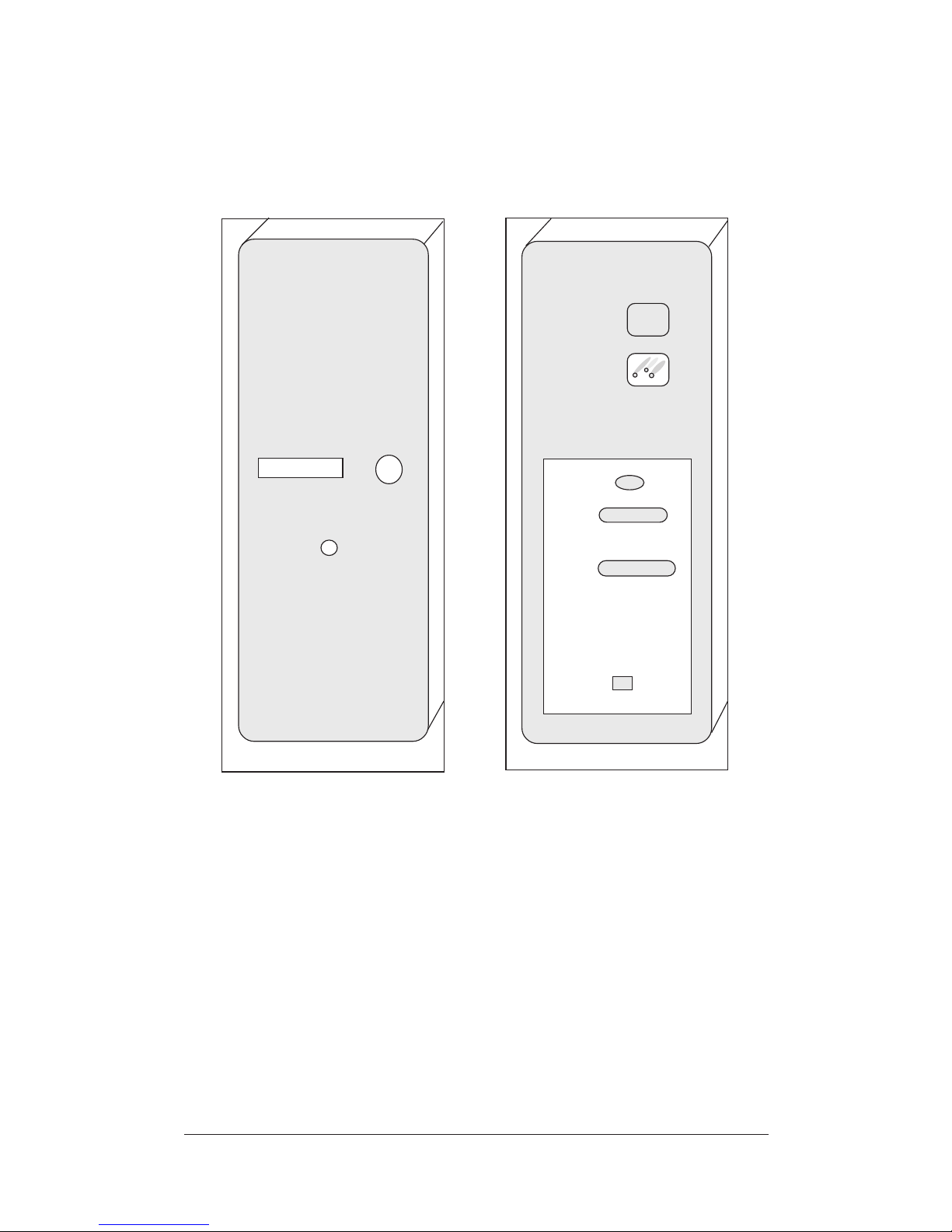
Layout
Power
On/OFF
Disk Drive
Reset
Button
Fr ont Vie w
Rear V iew
Pow er
Cord
Serial
Port
CN1/CN2
Parallel Port to PC
Monitor
Port
IMPORTANT:
1. Before connecting cables to the PCU-1, be sure to turn the power Off.
2. If the Printer connection is not being used, be sure the port is covered by a
plastic cap. Plastic caps are provided to cover the Serial Port, Parallel Port,
and lower Monitor Port, which are indicated in the Rear View illustration.
PCU-1
PCU-1
Page 12
The Print Controller 1-6
The Print Controller
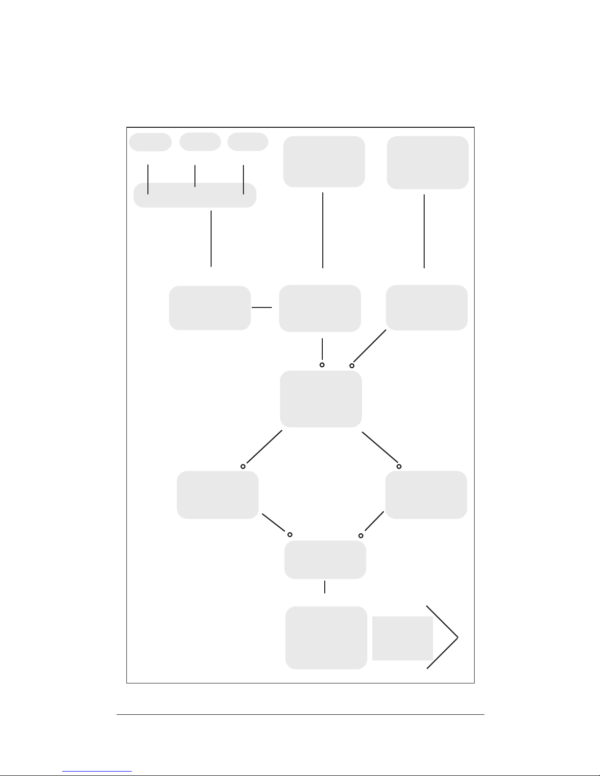
I/O Interfaces
V
PCU-1
Memory
PostScript
Interpreter
Network
Interface Card
Controller
Interface
Serial
Port
Parallel
Port
PCL 5E
Interpreter
Input Buffer
VVV
Server Mac PC
-------Ethernet--------
PC or Print
Server
PC or Print
Server
>
to Printer
NC-3
Page 13

The Print Controller 1-7
Most of the memory in the PCU-1 is used for rasterizing the image. A small
portion is used for the system operation (see NOTE).
The basic configuration of the PCU-1 includes 16 MB of RAM, which allows 1bit mode printing at 400 dpi on all paper sizes. The PCU-1 print controller may
be upgraded to 128 MB in 32 MB increments to allow 8-bit Grayscale printing
on Tabloid (11"x17") A3 pape r, or double buffering on smaller paper sizes.
When using the E-RDH in the one-sided mode, printing will be performed
simultaneously while the PCU-1 rasterizes the pages in the print job and sends
them to the E-RDH memory. While pages are being printed from the E-RDH
memory, the PCU-1 continues to rasterize the next print job in the sequence.
The more memory in the PCU-1, the more pages it can rasterize while waiting
for the previous job to print. A typical example of the memory requirements for
a Letter page is as follows:
1-Bit 8-Bit
400 DPI 1,870 Kbytes 14.96 Mbytes
600 DPI 4,207 Kbytes 33.66 Mbytes
32 MBytes installed=15 pages @1-Bit, 400 DPI
NOTE: ~2.7 MB is used for the system.
You may select various image quality modes from your print driver screen to
produce various levels of grayscale. The following Table shows the available
image quality modes and the grayscale levels they produce.
Print Mode Print Engine Print Controller Grayscale
Text 1-Bit Mode 1-Bit Mode 2 Levels
Medium 2-Bit Mode 8-Bit Mode 4 Levels
High 4-Bit Mode 8-Bit Mode 16 Levels
Very High 8-Bit Mode 8-Bit Mode 256 Levels
The Print Controller
Memory Configuration
Page 14

The Print Controller 1-8
The Print Controller
Specifications
System
Architecture IBM Compatible PC System
Processor 200 MHz Intel Pentium MMX
Memory 16 MB standard/128 MB max.
Hard Drive IDE compatible
Floppy Drive 3.5" Floppy Disk
Input/Output Interfaces
Serial RS-232C Serial Standard
Connector DB9 male
Baud Rates 4,800~19,200 (default: 19,200)
Parallel IEEE 1284 compatible bidirectional
Network Connectivity Compatible
Optional NC-3
Ethernet Network Interface (10BaseT/100BaseT)
PDL Support
Standard PCL 5E
Optional PostScript
Font Suppor t
PCL 45 PCL Fonts
PostScript 35 PostScript Fonts (optional)
Driver Software
Windows 3.1, 3.11, Windows 95
Windows NT Workstation & Server
ver. 3.x, 4.x
Macintosh environment
Print Controller Features
Multiple Page Buffering
Document Printing
Automatic Emulation Switching
Automatic Port Switching
Page 15

Section 2: Printer Drivers
Installing Printer Drivers
Checking Printer Driver Version
About Printer Driver Screens
Vi 550(Ai 5555) Print Mode LCD
Vi 550(Ai 5555) Printer Driver Screens
PostScript Driver for Windows 3.1
PCL Driver for Windows 95
PostScript Driver for Windows 95
Printing Modes
Tray Selection/Paper Selection
Font Selection
Font Characteristics
PostScript Printer Langsge Fonts
PCL 5 Printer Language Fonts
Page 16

2-2 Printer Drivers
Printer Drivers
Installing Printer Drivers
Printer Drivers that come with your PCU-1 Print Controller are actually software programs, enabling you to control printing settings for the selected printer.
Before you can print from your application (e.g., spreadsheet or word processor),
the appropriate printer driver must be installed on your computer system.
The installation procedure is similar for all printer drivers. The example shown
below is for the Windows 3.x printer driver, and includes the following steps:
• Installing a specific printer driver
• Assigning a port to the printer
• Specifying settings for your printer (optional)
• Setting the default printer
Installing a Specific Printer Driver
(Example: Windows 3.x)
1. Double-click the Main icon in Program Manager.
2. Choose the Control Panel icon.
3. In the control Panel window, choose the Printers icon.
4. Choose the Add button.
5. In the List Of Printers box, select Install Unlisted or Updated Printer.
Depending upon the printer driver version, you may need to use the Browse
button to find and select the driver. Then, click on OK until you get to the
Add Unlisted or Updated Printer box.
NOTE: To install a driver that is listed, but not installed, simply highlight it in List of Printers box.
6. Choose the Install button.
7. Insert the disk containing the printer driver into your floppy drive, The
default for the drivers is drive A. If you are using a different drive,
specify it. When the appropriate drive is selected, click on OK.
8. In the Add Unlisted or Updated Printer box, select the appropriate driver and
click on OK.
9. The printer name will appear in the list of installed printers.
Page 17

Printer Drivers 2-3
Printer Drivers
Installing Printer Drivers
Assigning a Port
By default, LPT1 will be assigned to the newly installed printer.
1. To assign a different port, click on the Connect button.
2. In the Ports list, select the port you want to assign to the printer.
NOTE: When installing to a network, up to three LPT printers can be assigned (LPT1, LPT2, LPT3)
without having to add more through the WIN.INI file. Should it be necessary to add more than three
printers, click on the Help button in the Connect box for instructions.
Tip: If you print to LPT1 in Windows 3.x and LPT1 is redirected to another port,
the printer will not print. To correct this, select LPT1.DOS in the Connect dialog
box.
Specifying Printer Settings
This is an optional step for making changes to the default printer settings, such as
paper size or orientation. These settings can be temporarily overridden from
within your application.
1. Click on the Setup button in the Printers dialog box.
2. When the Setup box is displayed, make the desired selections.
Setting the Default Printer
When you install a printer, it will automatically be highlighted in the Printers
dialog box.
1. Highlight the printer you want as the default printer.
2. Click on the Set As Default Printer button.
NOTE: Some applications act as a control panel, making their settings become the system default.
This is not a function of the driver.
Page 18

2-4 Printer Drivers
Printer Drivers
Checking Printer Driver Version
There may be times when you need to know if you are using the most up-to-date
printer driver.
The procedure shown below for Windows 3.x is similar for all printer drivers.
Check the Printer Driver Version for Windows 3.x
1. Highlight the driver in the Printers dialog box.
2. Click on the Setup button.
3. Click on the About button.
4. The About dialog box will be displayed with the printer version shown.
Page 19

Printer Drivers 2-5
Printer Drivers
About Printer Driver Screens
When you select Print from your application screen, the screen that displays is
specific for your installed printer driver, e.g., PostScript for Windows 3.1, PCL
for Windows 95 or PostScript for Windows 95.
You may use the default settings shown on your screen or you may select options
available for each printing mode. The basic procedure for making print selections on the Vi 550(Ai 5555) printer is shown at the bottom of this page.
T o view the specific printer driver screens you will encounter when using the
PostScript printer driver for Windows 3.1, PCL printer driver for Windows 95,
or PostScript printer driver for Windows 95, see p. 2-19.
NOTES:
1. Windows 3.1 screens are similar to those in Windows for Workgroups and
many Windows 95 screens are similar to those in WindowsNT.
2. For a description of available Printing Modes and Fonts, see the pages
following the sample driver screens at the end of this Section.
Making Print Selections From Your Printer Driver Screen
Example:
1. From your printer driver screen, click on the desired printing mode.
2. Scroll options associated with the mode by clicking the up or down arrows.
3. When all desired settings are indicated on the screen, click on OK.
Page 20

2-6 Printer Drivers
Vi 550(Ai 5555) Print Mode LCD
Paper Loading
Check Mode/Print Start Message
Printer Mode Icons
Check Mode
Using the Check Mode
Using the PROOF PRINT Option
When Settings are Not OK
Stop/Clear Mode
Interrupt/Reserve Mode
When Printiing is in Progress
Job Status Display
Copier/Printer
Copier
Controller Mode
Page 21
Printer Drivers 2-7
Printer Drivers
Vi 550(Ai 5555) Print Mode LCD
The Vi 550(Ai 5555) Printer main body includes an LCD with an interactive
Basic Screen and sub-screens that display the status of the print engine and
printing operations and enable you to make selections and changes, as needed.
NOTE:
The basic screen for the Copier Mode is described in a separate Instruction Handbook.
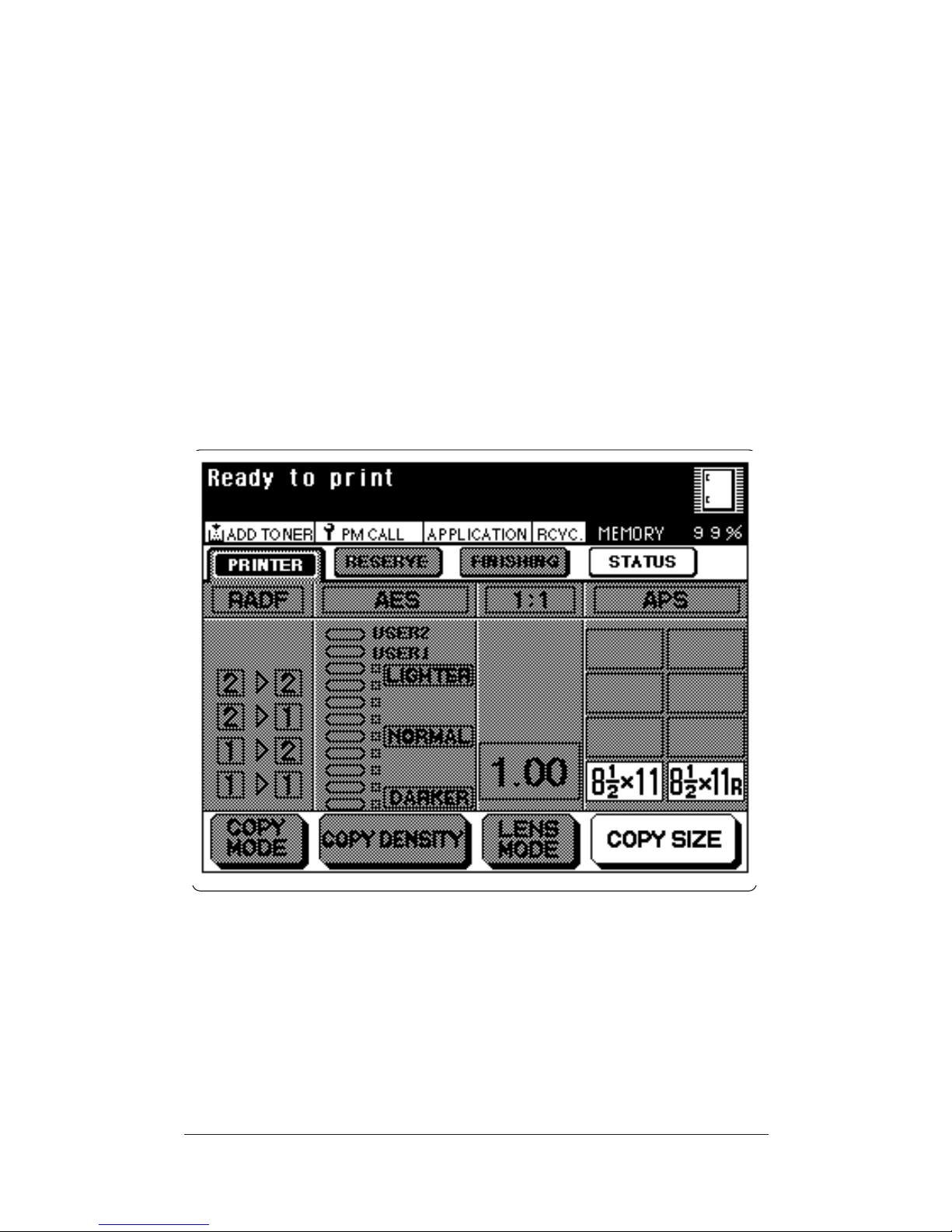
Screen Configuration
The Basic Screen of the Printer Mode consists of a Message area, an icon area, a
Folder area and a Mode area, similar to the Basic Screen of the copier mode.
Page 22
2-8 Printer Drivers
Printer Drivers
Vi 550(Ai 5555) Print Mode LCD
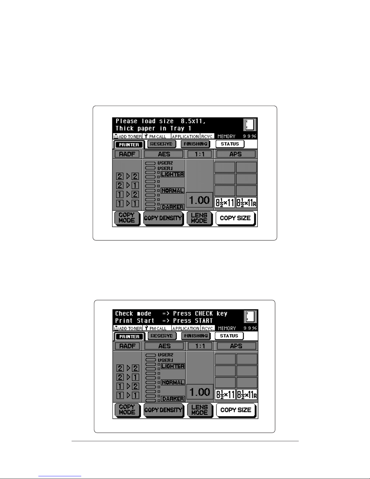
Paper Loading
If the setting of your print controller does not designate a specific paper tray, the
following message is displayed on the screen.
Check Mode/Print Start
If a "WAIT COMMAND' is designated by the controller, the following message
will display on the screen to give you the option of using the Check Mode before
printing. If you do not wish to use the Check Mode, you may press the START
key and print right away. The Check Mode/Print Start message is shown below.
Page 23
Printer Drivers 2-9
Printer Drivers
Vi 550(Ai 5555) Print Mode LCD
Printer Mode Icons
The following icons display on the LCD screen to indicate printer mode status.
INITIAL: The Printer Controller is in the initialization mode.
PRINT: The Printer controller is currently printing.
ERROR: The Printer Controller generated an error message.
READY: The Printer Controller is ready for printing.
IDLE: The Printer Controller is waiting for a print job.
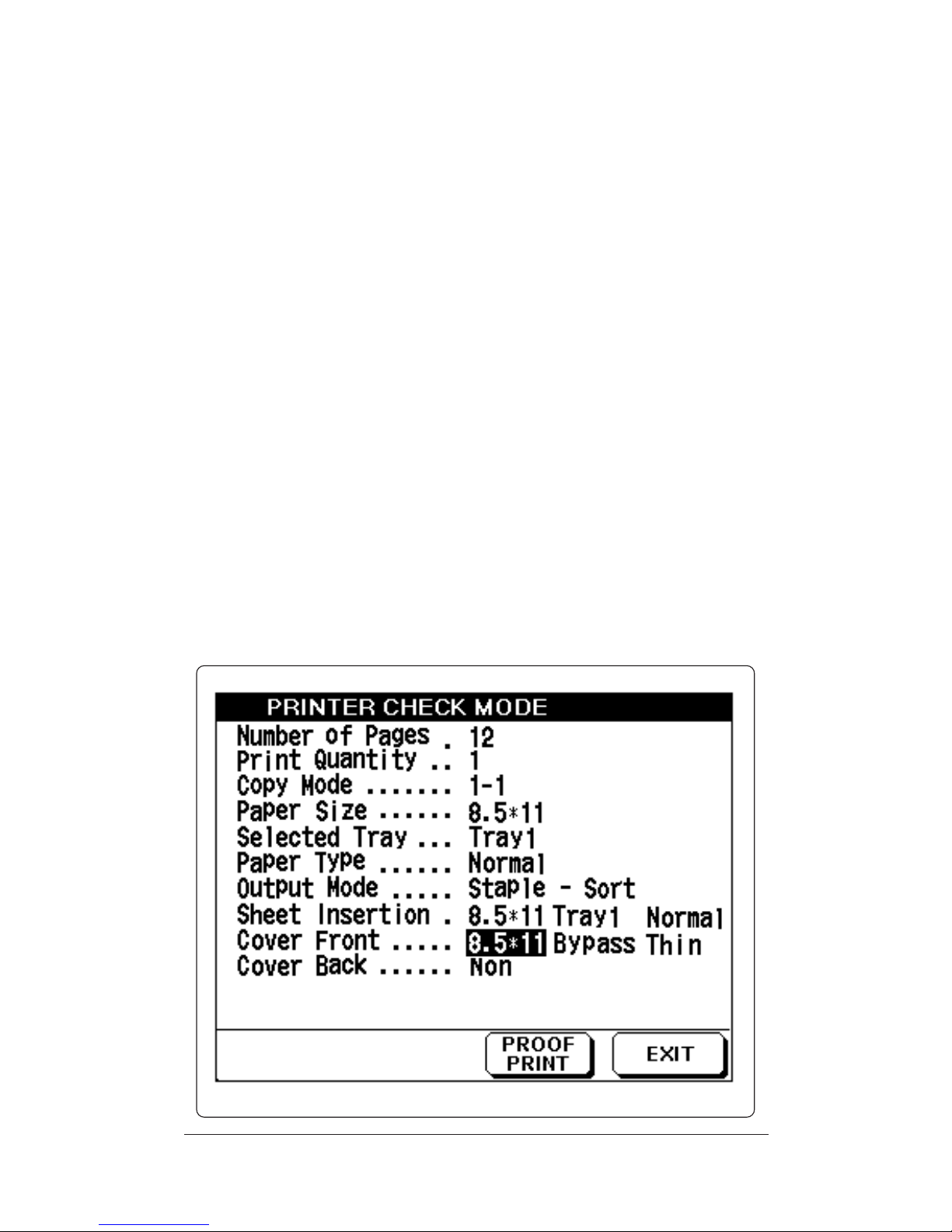
Using the Check Mode
As mentioned on the previous page, the setting of your print controller determines whether or not the Check Mode/Print Start message will be displayed.
The Check Mode/Print Start display gives you the following options:
• view current settings on the PRINTER CHECK MODE screen
• select a PROOF PRINT
• press the START key and print right away
Sample PRINTER CHECK MODE Screen
Page 24

2-10 Printer Drivers
Printer Drivers
Vi 550(Ai 5555) Print Mode LCD
Using the Check Mode
Selecting Check Mode
1. Press the Check key while the Check Mode/Print Screen message is
displayed. (See sample screen on previous page.)
2. When the PRINTER CHECK MODE screen is displayed, view the list
of current print mode settings to be sure they are OK. (See sample
screen on previous page.)
3. Completing the Check Mode
If settings are OK, press EXIT to escape the Check mode and return to
the Check Mode/Print Start message screen, then press the START key
to start printing the job.
NOTE: In case you need to check the settings again before pressing the
ST ART key, press the CHECK key again.
Using the PROOF PRINT Option
If settings are OK and you want to see how the printed job will
look before printing out multiple sets, press PROOF PRINT to print out
only one set. If the printing result is as expected, press the START key
to print out the complete job. Otherwise, see below.
When Settings are Not OK
If you need to make changes after checking the settings or viewing the
PROOF PRINT sample, press EXIT to escape the Check Mode,
then press the Stop/Clear key to cancel the print job and make other
settings, as required.
NOTE: When the sheet insertion paper size is highlighted on the PRINTER
CHECK MODE SCREEN, the insert sheets will be blank; when the size indication is not highlighted, the insert sheets will be copied.
Page 25
Printer Drivers 2-11
Printer Drivers
Vi 550(Ai 5555) Print Mode LCD
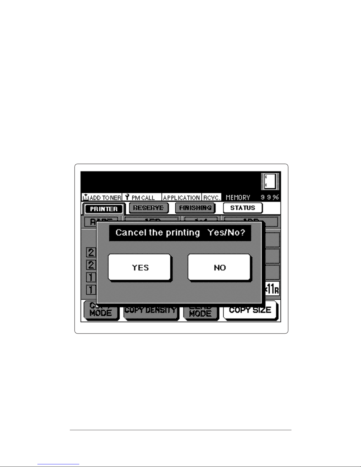
Stop/Clear Mode
The Stop/Clear key can be pressed to cancel a print job while printing is in
progress. After pressing the Stop/Clear key, you will be prompted with a
confirmation screen to select YES/NO to cancel printing.
1. While a job is currently printing, press the Stop/Clear key to cancel the
job.
2. The following YES/NO confirmation screen will be displayed.
Press YES to confirm the cancelation.
Press NO to continue printing without canceling the job.
Page 26
2-12 Printer Drivers
Printer Drivers
Vi 550(Ai 5555) Print Mode LCD
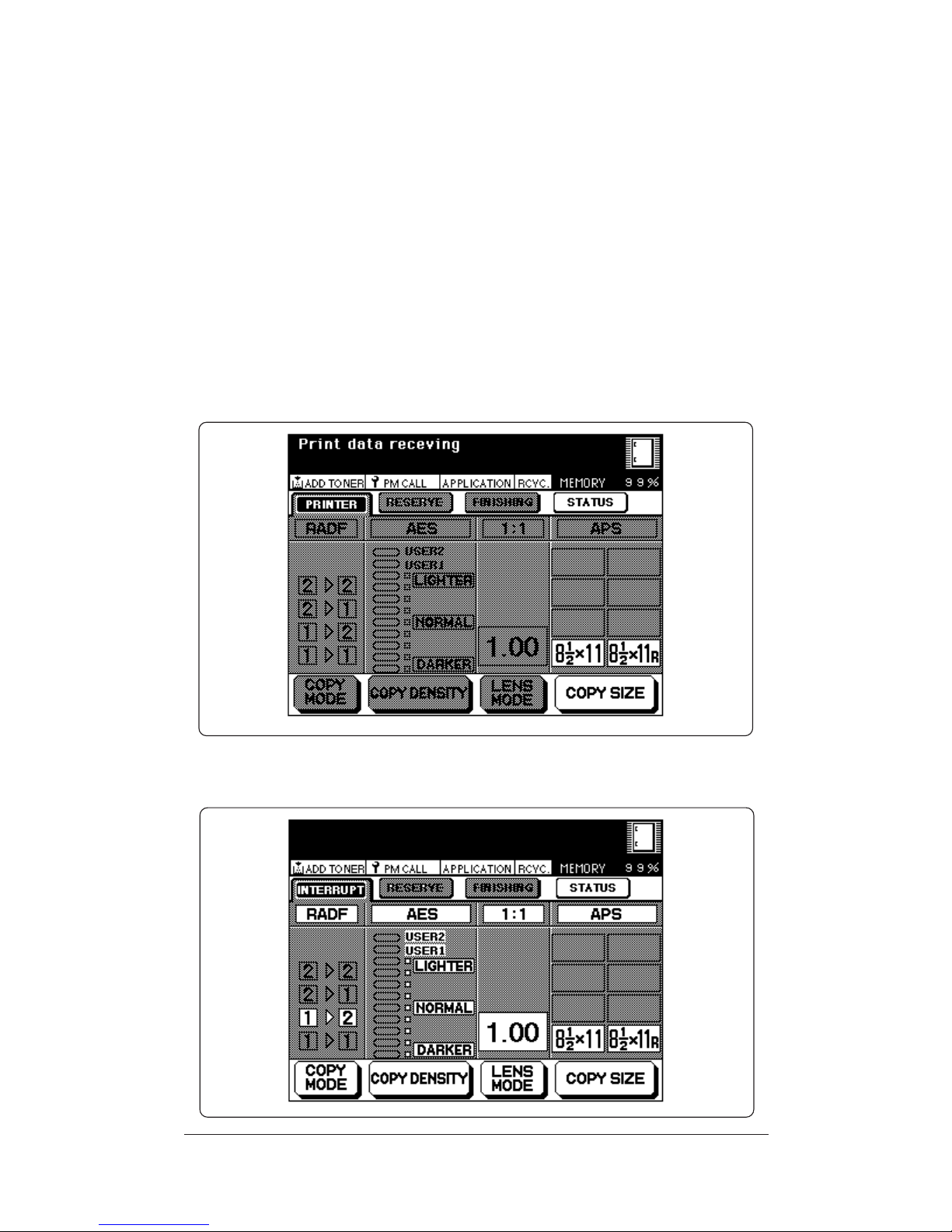
Interrupt/Reserve Mode
The Interrupt mode can be used to interrupt the current printing operation to
perform a copying job. The Interrupt mode can be selected when the engine is
receiving print data or when printing is already in progress. Each case is handled
in a different way, as described below.
When the engine is receiving print data:
1. Press the Interrupt key when the engine is receiving print data.
Print data receiving will be displayed in the message area of the screen.
2. Copy the document. After copying is completed, press the Interrupt key
again to enable the engine to resume the print mode.
Page 27

Printer Drivers 2-13
Printer Drivers
Vi 550(Ai 5555) Print Mode LCD
When printing is in progress:
1. Press the Interrupt key when printing is in process.
Printing in progress will be displayed in the message area of the screen
and the RESERVE mode folder will be displayed.
2. Press the RESERVE folder to set the conditions for a copying job that
will be performed after the print job in progress is completed.
The engine will automatically resume the print mode.
Page 28

2-14 Printer Drivers
Printer Drivers
Vi 550(Ai 5555) Print Mode LCD
Job Status Display
The STATUS folder appears on the basic screen for each job (copying job or
print job) to allow you to check the status of the job in realtime.
When the STATUS folder is pressed, the JOB STATUS DISPLAYscreen
displays. The display is different for a COPIER/PRINTER job and a COPIER
job, as shown on the next pages.
Page 29

Printer Drivers 2-15
Printer Drivers
Vi 550(Ai 5555) Print Mode LCD
Job Status Display (continued)
COPIER/PRINTER
NOTE: The above screen shows that scanning is in progress via the controller
for the Printer job.
CONT ROLLER
PRINTER
Page 30

2-16 Printer Drivers
Printer Drivers
Vi 550(Ai 5555) Print Mode LCD
Job Status Display (continued)
The screen below shows the JOB STATUS DISPLAY for a copier job.
COPIER
NOTE: The above screen shows that scanning is in progress via the controller
for the Reserve Copier job.
Page 31

Printer Drivers 2-17
Printer Drivers
Vi 550(Ai 5555) Print Mode LCD
Controller Mode
The Controller Mode screen information is specified by the controller (see Print
Controller Specifications, p. 1-8).
To enter the Controller Mode
1. Press the MODE button to enter the Controller mode.
To release the Controller Mode
2. Press the MODE button again to escape from the Controller mode.
Page 32

2-18 Printer Drivers
Vi 550(Ai 5555) Printer Driver Screens
PostScript Driver for Windows 3.1
PCL Driver for Windows 95
PostScript Driver for Windows 95
Page 33

Printer Drivers 2-19
Printer Drivers
Vi 550(Ai 5555) Printer Driver Screens
PostScript Driver for Windows 3.1 General Screen
The General Screen is the first screen that displays after you click on
Print from your applications screen. This screen allows you to select OK
when the default settings are acceptable. Otherwise, you may do the
follo wing:
• Click on the Paper Size arrow to select another paper size
• Click on the Paper Source arrow to select a specific tra y
(see screen below)
• Click on Options to make other selections
The default for Paper Source is AutoSelect which means that the printer
will select an appropriate tra y for the paper size indicated.
If you select a specific tr a y, the system will look for the paper size in that
tra y. In that case, be sure to load the appropriate paper size in that tray.
Paper Source
Mita Vi550 (Ai5555) PS
Mita Vi550 (Ai5555) PCL
Page 34

2-20 Printer Drivers
Printer Drivers
Vi 550(Ai 5555) Printer Driver Screens
PostScript Driver for Windows 3.1 Options Screen
The Options screen displays Printer features that allow you to control the
finishing style of your print job, as follows:
• Offset each set when making multiple sets
• Staple each output set
• Use Print Quality with High Resolution for graphic images
• Use Special modes of 2-in-1, 4-in-1, Booklet
• Use Insert tray to insert special paper in the manual tray
Page 35

Printer Drivers 2-21
Printer Drivers
Vi 550(Ai 5555) Printer Driver Screens
PostScript Driver for Windows 3.1 Advanced Options Screen
The Advanced Options screen allows you to select:
• Fonts
To change the default font currently in use, click the arrow in the Send to
Printer field to display the options.
• Memory
Increase the amount of memory allocated for storing pages.
• Graphics
Change resolution to handle complicated text or halftone images.
Page 36

2-22 Printer Drivers
Printer Drivers
Vi 550(Ai 5555) Printer Driver Screens
PostScript Driver for Windows 3.1 Offset Mode
When printing multiple sets, use the Offset mode to separate one printed
set from another.
Click Offset to displa y the current On/Off setting.
Click on the desired option and click on OK.
Page 37

Printer Drivers 2-23
Printer Drivers
Vi 550(Ai 5555) Printer Driver Screens
PostScript Driver for Windows 3.1 Staple Mode
When printing multiple sets, use the Staple mode to staple each set.
Click on Staple to display the current setting.
If the current setting is acceptable , click OK.
Click on the arrow to view setting options.
• Single Portrait mode places a staple in the upper left corner of a
portrait document.
• Single Landscape mode places a single staple in the upper left
corner of a landscape document.
• Double Staple mode places two staples along the left edge of a
portrait or landscape document.
Page 38

2-24 Printer Drivers
Printer Drivers
Vi 550(Ai 5555) Printer Driver Screens
PostScript Driver for Windows 3.1 Print Quality
Use the Print Quality mode when your image includes graphics or halftones requiring a resolution that is higher than the Text mode.
Click on Print Quality to display the current setting. Select the mode that
is appropriate for the original image. Click the arrow to view further
availab le setting options.
Use the V ery high mode for true grayscale printing.
Page 39

Printer Drivers 2-25
Printer Drivers
Vi 550(Ai 5555) Printer Driver Screens
PostScript Driver for Windows 3.1 Print Density
Print Density allows y ou to print with reduced toner consumption.
Click on Print Density to display the current setting. The default setting is
Normal.
To change the Print Density setting, click on the desired mode or click on
the arrow to view further options.
• Toner Saver mode uses 80% of the toner normally used.
• Draft mode uses 60% of the toner normally used.
Page 40

2-26 Printer Drivers
Printer Drivers
Vi 550(Ai 5555) Printer Driver Screens
PostScript Driver for Windows 3.1 Edge Smoothing
Click on Edge Smoothing to display the current setting.
• Edge Smoothing Off
The default setting is Off.
• Edge Smoothing On
Edge Smoothing enhances the images of text or objects by filling in the
feathered edges with e xtra toner .
Page 41

Printer Drivers 2-27
Printer Drivers
Vi 550(Ai 5555) Printer Driver Screens
PostScript Driver for Windows 3.1 Wait Mode
Click on the W ait Mode to display the current setting.
• Wait Mode Off
The default setting for Wait Mode is Off, which means you will not be
prompted to load special paper .
If your printer is also set for "fixed-tray/paper configuration," printing will
be performed without any further action required, provided the fixed tray
is loaded with the appropriate paper size.
• Wait Mode On
If you select "W ait" mode On, the system will prompt you to insert the
selected paper. Use this setting when your printer is set for "flexible tr ay/
paper configuration" or when you do not know the tray setting.
• Wait with Proof
You may also select "Wait with Proof" if you want the system to prompt
you to print out a proof sheet after you insert paper in the tra y.
Page 42

2-28 Printer Drivers
Printer Drivers
Vi 550(Ai 5555) Printer Driver Screens
PostScript Driver for Windows 3.1 Special Modes
Click on Special Modes to displa y the current setting in the block below.
The default setting is None.
Click on another desired setting, or clic k the arrow to view further available options.
• Select 2-in-1 mode to scan two pages into memory and copy them both
onto one standard size sheet.
• Select Booklet mode to scan four pages into memory and copy them all
onto one standard size sheet.
• Select Sheet Insertion to insert up to 15 blank or copied insert sheets at
the page locations you designate by page number.
NOTE: P age numbers should reflect the sequential pages of your docu-
ment.
Page 43

Printer Drivers 2-29
Printer Drivers
Vi 550(Ai 5555) Printer Driver Screens
PostScript Driver for Windows 3.1 Special Modes (cont.)
• Select Letterhead
The system will look for the tray that was previously programmed for
Letterhead. If paper is not installed, you will be prompted to install it.
• Select Front & Back Covers (blank or copied)
The system will insert these sheets as the first and last pages of your
document.
• Select Chapterization when using duplex or booklet mode
The system will insert blank pages at the end of each chapter, as required, to ensure that each new chapter starts on a right-hand page. A
blank sheet will be inserted bef ore each page number you designate
(max. 15 insert sheets).
NOTE: P age numbers should reflect the sequential pages of your document.
Page 44

2-30 Printer Drivers
Printer Drivers
Vi 550(Ai 5555) Printer Driver Screens
PostScript Driver for Windows 3.1 Insert Tray
Click on Insert Tra y to display the current tray setting.
When Manual tray is selected, the system will prompt you to load paper in
the manual tray.
If you change the tray setting to Tray 1, for example, the system will only
use that tray for the print job.
Page 45

Printer Drivers 2-31
Printer Drivers
Vi 550(Ai 5555) Printer Driver Screens
PostScript Driver for Windows 3.1 Paper Type
Select Paper Type to display the current setting. The default setting is
Plain Paper .
Select the special type paper you want to insert in the manual tray, such
as, OHP transparency, thin paper, or thick paper.
The system will prompt you to load the special paper in the manual tray.
Page 46

2-32 Printer Drivers
Printer Drivers
Vi 550(Ai 5555) Printer Driver Screens
PostScript Driver for Windows 3.1 Output Bin
Click on Output Bin to display the current setting for the output tray of the
Finisher. The default tray is the middle tray.
This setting can be changed to control a special or high volume job you
want to run from one source.
To change the setting, click another option for the output tray. Or, click the
arrow to view further setting options.
Page 47

Printer Drivers 2-33
Printer Drivers
Vi 550(Ai 5555) Printer Driver Screens
PostScript Driver for Windows 3.1 Output Order
Click on Output Order to display the current setting. The default setting is
F ace Up, which is speedier than Face Down mode.
F ace Up mode is OK when the sequential order for your document is not
required.
Select Face Down mode when the sequential order for your document is
required.
Page 48

2-34 Printer Drivers
Printer Drivers
Vi 550(Ai 5555) Printer Driver Screens
PCL Driver Screens for Windows 95 General Screen
The General Screen displays tabs for all available properties settings for
the PCL Driver.
Just click the tab topic you require and the appropriate screen will be
display ed .
Should you decide not to go further with any selection, click the Cancel
button at the bottom of the screen.
Mita Vi550 (Ai5555) PCL
Mita Vi550 (Ai5555) PCL
Page 49

Printer Drivers 2-35
Printer Drivers
Vi 550(Ai 5555) Printer Driver Screens
PCL Driver Screens for Windows 95 Details Screen - Printer Port
Click the Details tab to display the current printer port setting.
Click the arrow for options, then select the port you want.
This screen also allows you to change the current time interval used for
capturing files for printing.
To print very large files, you may need to adjust this timeout setting. In
most cases, y ou will not need to change this setting.
Mita Vi550 (Ai5555) PCL
Mita Vi550 (Ai5555) PCL
Mita Vi550 (Ai5555) PCL
Page 50

2-36 Printer Drivers
Printer Drivers
Vi 550(Ai 5555) Printer Driver Screens
PCL Driver Screens for Windows 95 Setup Screen - Paper Size
Click the Setup tab to displa y the current paper size.
Click on the arrow to scroll through the available choices, then select the
desired paper size .
You may also switch from the usual Portrait orientation to Landscape
orientation, which places the readable printed image widthwise rather
than lengthwise.
Mita Vi550 (Ai5555) PCL
Page 51

Printer Drivers 2-37
Printer Drivers
Vi 550(Ai 5555) Printer Driver Screens
PCL Driver Screens for Windows 95 Setup Screen - Paper Tray
Click on the Setup tab.
The current setting for paper tray is AutoSelect, which enables the printer
to automatically select the appropriate paper.
If you w ant to specify an output tra y, click on the arrow to displa y the
available options, then double click the desired tray.
Mita Vi550 (Ai5555) PCL
Page 52

2-38 Printer Drivers
Printer Drivers
Vi 550(Ai 5555) Printer Driver Screens
PCL Driver Screens for Windo ws 95 Setup Screen - Resolution
Click on the Setup tab. The current Resolution setting is 400 dpi.
To change the current setting, click on the arrow to display the available
settings.
Double click the Resolution of your choice, then click OK.
Mita Vi550 (Ai5555) PCL
Page 53

Printer Drivers 2-39
Printer Drivers
Vi 550(Ai 5555) Printer Driver Screens
PCL Driver Screens for Windows 95 Watermarks Screen - General
Click on the W atermar ks ta b. The default setting is None.
Select the appropriate W atermark option to indicate the special condition
of your printed document, such as, Confidential, Cop y, or Draft.
After selecting a Watermark type, the Edit screen will automatically
display to allow y ou to select the details, as shown on the next page.
Mita Vi550 (Ai5555) PCL
Page 54

2-40 Printer Drivers
Printer Drivers
Vi 550(Ai 5555) Printer Driver Screens
PCL Driver Screens for Windo ws 95 Watermarks Screen - Edit
(continued)
The Edit screen allows you to enter text, font type, point size, color, and
style, for y our Watermark.
You may also control Saturation and Intensity by clicking the arrows until
the setting you want is displa yed.
The Angle setting lets you display the printed Watermark at an angle .
Click on the arrows next to Angle to scroll to the desired angle setting.
When all the settings are displayed correctly, click OK.
Page 55

Printer Drivers 2-41
Printer Drivers
Vi 550(Ai 5555) Printer Driver Screens
PCL Driver Screens for Windows 95 Fonts Screen - General
Click on the Fonts tab to display the current font settings.
If you need to edit the F ont Substitution Table, click on the first item to
display the appropriate editing screen.
(See a sample of the Edit Table screen on the next page. )
Mita Vi550 (Ai5555) PCL
Page 56

2-42 Printer Drivers
Printer Drivers
Vi 550(Ai 5555) Printer Driver Screens
PCL Driver Screens for Windo ws 95 Fonts Screen - Edit Table
(continued)
Send host fonts to the printer.
The font Substitution Table enab les you to specify the host fonts that you
want to be replaced with built-in printer f onts. Printing is faster with built-in
printer fonts.
In this screen, the Arial font is downloaded. Use the arrow to scroll to the
availab le options.
Use the arrows to scroll through the font list to see how they are currently
specified.
If no changes are required, click Cancel.
Page 57

Printer Drivers 2-43
Printer Drivers
Vi 550(Ai 5555) Printer Driver Screens
PCL Driver Screens for Windows 95 Device Options - Installable Options
Click on the Device Options tab to display the Installable Options screen.
This screen displays the currently installed finishing device along with
installable options.
Mita Vi550 (Ai5555) PCL
F8220
F8220
Page 58

2-44 Printer Drivers
Printer Drivers
Vi 550(Ai 5555) Printer Driver Screens
PCL Driver Screens for Windows 95 Finishing - Stapling/Job Offset
Click on the Finishing tab to view the default settings.
Job Offset is On, as indicated by the check. The Stapling function is off
and the Output Order is Face Up.
Select any options for your print job. When the job is completed, the
default settings will resume .
NOTE: Default settings can be changed from the Windows Printer screen.
Mita Vi550 (Ai5555) PCL
Page 59

Printer Drivers 2-45
Printer Drivers
Vi 550(Ai 5555) Printer Driver Screens
PCL Driver Screens for Windows 95 Media Settings - Print Density
Click the Media Settings tab to view current settings. The default setting
for Print Density is Normal.
F or a ny given job, you may select Toner Save mode or Draft mode. These
modes help you conserve toner consumption by using considera bly less
toner .
When printing is completed, the default setting will resume.
Mita Vi550 (Ai5555) PCL
Page 60

2-46 Printer Drivers
Printer Drivers
Vi 550(Ai 5555) Printer Driver Screens
PCL Driver Screens for Windo ws 95 Media Settings - Media Type
Click the Media Settings tab to view the crent settings. The default setting
for Media Type is Plain Paper.
Double click on the setting you want, then click OK.
If you select one of the option settings, the default setting for Plain Paper
will resume when the print job is completed.
Mita Vi550 (Ai5555) PCL
Page 61

Printer Drivers 2-47
Printer Drivers
Vi 550(Ai 5555) Printer Driver Screens
PCL Driver Screens for Windo ws 95 Job Settings - Special Modes
Click the Job Settings tab to display the current settings. The default
setting for Special Modes is None.
Click on the arrows to display setting options:
• 2-in-1 mode scans two pages and prints them onto one sheet.
• Booklet mode scans four pages and prints them onto one sheet.
• F ront/Back Covers inserts a page at beginning and end of each set.
• Separator pages inserts a sheet at designated locations.
Double click on the setting mode you want, then click OK.
Mita Vi550 (Ai5555) PCL
Page 62

2-48 Printer Drivers
Printer Drivers
Vi 550(Ai 5555) Printer Driver Screens
PCL Screens for Windows 95 Job Settings - Duplex Mode
Click on the Job Settings tab to display the current settings. The default
setting for Duplex Mode is Off. Click on the arrow to view options.
You may select Short Edge Binding for landscape orientation or Long
Edge Binding for portrait orientation.
Double click on the setting(s) you want, then click OK.
Mita Vi550 (Ai5555) PCL
Page 63

Printer Drivers 2-49
Printer Drivers
Vi 550(Ai 5555) Printer Driver Screens
PCL Driver Screens for Windo ws 95 Job Settings - Wait Mode
Click the Job Settings tab to display the current settings. The default
setting for W ait Mode is Off.
If you select Wait, you will be prompted to insert the correct paper before
printing begins.
If you select Wait with Proof, y ou will be prompted to print a proof set
before printing multiple sets.
Double click on the setting mode you want, then click OK.
Mita Vi550 (Ai5555) PCL
Page 64

2-50 Printer Drivers
Printer Drivers
V i550(Ai5555) Printer Driver Screens
PostScript Driver Screens for Windows 95 General Scr een
The General Screen shows you the basic tab layout associated with printing
properties. Clicking on each tab brings you to new screen options. Click on
Browse to check out the environment and get questions answered upfront. O r,
click Print T est Page to print a test page automatically.
Type a key word in the Comment field and click OK. The system will search for the
topic and guide you further.
Click on the arrow to display further def ault settings associated with the general
printing properties .
Mita Vi550 (Ai5555) PS
Mita Vi550 (Ai5555) PS
Page 65

Printer Drivers 2-51
Printer Drivers
V i550(Ai5555) Printer Driver Screens
PostScript Driver Screens for Windows 95 Device Options - Print Quality
The Device Options tab displays several setting options along with the available
printer memory. Click the arrows to scroll to other memory options.
Select an option by clicking on it. Or, click on the arrows to view further available
options.
The setting for Print Quality shows that Text is the current setting. Click the arrow
next to Text to vie w further options.
The installed Finisher type is identified in the Installable options field. Use the
arrow in the low er field to display other installed devices, such as, Large Capacity
Tray, etc.
F8220
Finisher Installed F8220
Mita Vi550 (Ai5555) PS
Page 66

2-52 Printer Drivers
Printer Drivers
V i550(Ai5555) Printer Driver Screens
PostScript Driver Screens for Windows 95 Device Options - Edge Smoothing
Click on the Device Options tab. The default for Edge Smoothing is Off.
To select Edge Smoothing click the arrow under Change setting for Edge Smooth-
ing and select On.
Edge Smoothing fills in the feathered edges with ext ra toner to make a crisp
printing result.
Finisher Installed F8220
F8220
Mita Vi550 (Ai5555) PS
Page 67

Printer Drivers 2-53
Printer Drivers
V i550(Ai5555) Printer Driver Screens
PostScript Driver Screens for Windows 95 Device Options - Print Density
Click on the Device Options tab. The default for Print Density is Normal.
Click on the arrow under Change setting f or Print Density and select another
option, such as, Toner Sav e mode or Draft mode, etc.
Toner Save mode uses 80% of the amount of toner used in Normal mode.
Draft mode uses 60% of the amount of toner used in Normal mode.
F8220
Finisher Installed F8220
Mita Vi550 (Ai5555) PS
Page 68

2-54 Printer Drivers
Printer Drivers
V i550(Ai5555) Printer Driver Screens
PostScript Driver Screens for Windows 95 Device Options - Job Offset
Click on the Device Options tab. The default for Job Offset is Off.
Click on the arrow under the Change setting for Job Offset and select ON.
The Job Offset mode delivers multiple printed sets to the finisher with each set
offset from the other.
Finisher Installed
F8220
F8220
Mita Vi550 (Ai5555) PS
Page 69

Printer Drivers 2-55
Printer Drivers
V i550(Ai5555) Printer Driver Screens
PostScript Driver Screens for Windows 95 Device Options - Wait Mode
Click on the Device Options tab. The default for Wait mode is Off.
Click on the arrow under the Change setting for Wait Mode and select Wait or Wait
with Proof.
• Wait means that you will be prompted to install special paper, such as, OHP,
Thin or Thick.
• Wait with Proof means that you will be prompted to print a proof set
before printing multiple sets.
F8220
Finisher Installed
F8220
Mita Vi550 (Ai5555) PS
Page 70

2-56 Printer Drivers
Printer Drivers
V i550(Ai5555) Printer Driver Screens
PostScript Driver Screens for W indows 95 Device Options - Special Modes
Click on the Device Options tab to view current settings. The def ault setting for
Special Modes is None.
Click on the arrow under Change setting for Special Modes and select the desired
option.
• 2-in-1 scans two images and prints them on one standard size sheet.
• Booklet scans four images and prints them on one standard size sheet.
• With Letterhead selected, the system looks for the tray that is already
programmed for Letterhead. If the Letterhead tray is empty, you will be
prompted to insert paper.
F8220
Mita Vi550 (Ai5555) PS
Page 71

Printer Drivers 2-57
Printer Drivers
V i550(Ai5555) Printer Driver Screens
PostScript Driver Screens for Windows 95 Device Options - Insert Tray
Click on the Device Options tab. The default for Insert T r ay is None.
The None setting means that the system will automatically select an appropriate
tray that contains the desired paper siz e.
Click the arrow under Change setting for Insert Tra y and select a specific tray.
When a specific tra y is selected, the desired paper must be installed in that tray;
otherwise, the job will not be printed.
F8220
Finisher Installed
F8220
Mita Vi550 (Ai5555) PS
Page 72

2-58 Printer Drivers
Printer Drivers
V i550(Ai5555) Printer Driver Screens
PostScript Driver Screens for Windows 95 Device Options - Output Order
Click on the Device Options tab. The default for Output Order is Face Up. The
F ace Up setting is OK when the sequential order of your printed document is not
required.
Click on the arrow under the Change setting f or Output Order and select Face
Down. The Face Down mode delivers your printed job f ace down in sequential
order. Use this mode when the proper order of the printed set is required.
Finisher Installed
F8220
F8220
Mita Vi550 (Ai5555) PS
Page 73

Printer Drivers 2-59
Printer Drivers
V i550(Ai5555) Printer Driver Screens
PostScript Driver Screens for Windows 95 Paper Setting - Paper Size
Click on the Paper tab. The default for Paper Size is Letter size.
Click on another paper size , as required.
Select Half-letter (5.5"x8.5"), Legal (8.5"x14") or Tab loid (11"x17").
The system will automatically use the selected paper size from an appropriate
paper source.
Mita Vi550 (Ai5555) PS
Page 74

2-60 Printer Drivers
Printer Drivers
V i550(Ai5555) Printer Driver Screens
PostScript Driver Screens for Windows 95 Paper Setting - Paper Source
Click on the Paper tab. The default for Paper Source is AutoSelect Tray.
Click on the arrow in the Paper source field to view setting options and select a
specific tray source.
If you select tray 5, for example, the system will look f or the selected paper size in
tray 5.
If the selected paper size is not installed in tray 5, the job will not be performed
until the correct paper size is installed in that tray.
Mita Vi550 (Ai5555) PS
Page 75

Printer Drivers 2-61
Printer Drivers
V i550(Ai5555) Printer Driver Screens
PostScript Driver Screens for Windows 95 Paper Setting - More Paper Options
Click on the Paper tab.
Click on More Options to view setting options and make changes as needed.
• The default for duplex printing is None.
• Use Flip on long edge to flip page orientation to portrait.
• Use Flip on short edge to flip page orientation to landscape.
The default for Paper type is Plain Paper.
Click on the arrow next to Paper type to view setting options for paper type.
Click on the arrow of the Output bin. The default bin is the Lower Bin.
Use the arrow to view further setting options for the finisher output tray.
If you select a specific tr a y, the system will look in that tray for the paper size you
request. In that case, be sure that paper is installed in the tray.
Page 76

2-62 Printer Drivers
Printer Drivers
V i550(Ai5555) Printer Driver Screens
PostScript Driver Screens for Windows 95 Graphic Screen - Resolution
Click on the Graphics tab. The default for Resolution is 400 dpi.
Click on the arrow to view setting options.
Click on the desired resolution setting, then press OK.
Mita Vi550 (Ai5555) PS
Page 77

Printer Drivers 2-63
Printer Drivers
V i550(Ai5555) Printer Driver Screens
PostScript Driver Screens for Windows 95 Graphic Screen - Halftoning
Click on the Graphics tab.
The default for Halftoning uses 400 dpi mode for text.
The V ery High mode will give you a true halftone result.
Mita Vi550 (Ai5555) PS
Page 78

2-64 Printer Drivers
Printer Drivers
Printing Modes
Output Quality
Output Quality options are only available with the PostScript print driver. The following
selections can be made directly from your print driver screen.
• High Mode
High Mode provides 16-level grayscale printing with 4 bits per pixel, the maximum
resolution available with 600 dpi selected. In this mode, each bit is produced from one of
16 grayscale levels. Use High Mode for photos and graphic images that require high
resolution.
• Medium Mode
Medium Mode provides 4-level grayscale printing. In this mode, each bit is produced
from one of 4 grayscale levels. Images produced in this mode are sharper than images
produced in the default Text mode. Medium Mode is useful for producing complicated
graphs and charts.
• Text Mode
Text Mode provides normal quality 2-level grayscale printing for 400 dpi or 600 dpi
resolution. In this mode, each bit is produced in one of 2 grayscale levels. This is the
default mode used for basic text output.
Page 79

Printer Drivers 2-65
Normal/Reverse Print Order
Some applications have a Reverse Print Order setting. When selected, the application
setting will do exactly as it indicates.
Duplex Mode
Stackless duplex means that the duplex mode makes unlimited 2-sided prints.
Mode Restriction: Duplex Mode cannot be used together with the manual Feed Tray or
Very High Mode.
Offset Stacker/Stapler
Multiple sets are copied and offset from each other with or without stapling.
Mode Restriction: Job Offset or Stapling cannot be used with the Manual Feed Tray.
NOTE:
When switching resolution, a few seconds may be required for temperature adjustment.
Page 80

2-66 Printer Drivers
Printer Drivers
Printing Modes
The PCU-1 controller supports a variety of finishing modes that are described below.
Actual performance depends upon the capability of your print engine.
2-in-1 Mode
Scan two pages into memory and copy them onto one standard size sheet. The images are
output in sequential order and arranged from left to right.
4-In-1/Booklet Mode
Scan 8.5"x11" images into memory and print them in signature booklet format on
11"x17" (folding to 8.5"x11") or on 8.5"x11"R (folding to 5.5"x8.5"). You may use either
1-1 or 1-2 mode with the Booklet mode.
Mode Restriction: Booklet mode cannot be used together with Sheet Insertion or the
Manual Feed Tray.
NOTE: Some applications, such as CorelDRAW, WordPerfect 6.0 for Windows, Apple
Laser Writer 8.x drivers, have the ability to generate Booklet documents and other
documents that have multiple images on one page. The PCU-1 cannot detect that any
one of these options has been selected in an application. Therefore, if the Booklet mode
is also selected in the PCU-1, output will not be as expected.
Dual Access
The Dual Access function provides an efficient means for your printer to handle two
different jobs simultaneously, even for a copier job and a print job.
The Electronic Recirculating Document Handler (E-RDH) allows the print engine to
receive a job while it is printing scanned or stored documents.
There are four types of Dual Access, as shown below:
• Printing during Copying
• Printing during Printing
• Copying during Copying
• Copying during Printing
In the Copier Mode, the print engine controls and creates messages for the LCD operation panel. The LCD generates two screen types, namely, the Status Screen, and the Job
Screen (a copier type tab-based screen).
When the Print Mode is selected, the PCU-1 Print Controller will take over the control of
the LCD operation panel screen and function according to its printing settings, values and
parameters.
Page 81

Printer Drivers 2-67
Printer Drivers
Printing Modes
Image Density Selection
Controlling the Print Density level provides an efficient way to save toner. You may select
this function directly from your printer driver screen. There are three distinct Print
Density modes that can be used. Each mode is listed below along with its corresponding
level of toner usage.
• Normal Mode 100% toner usage
• Toner Save Mode 80% toner usage
• Draft Mode 60% toner usage
Wait Mode
The Wait Mode is available from your printer driver screen.
• Wait Mode Off
Use Wait Mode Off to save time when your printer has a "fixed tray/paper configuration"
by allowing printing to take place without further prompting.
• Wait Mode On
Use Wait Mode On when your printer has a "flexible tray/paper configuration" or when
you do not know the tray configuration. In this case, the system will prompt you to load
the appropriate paper type in the tray.
• Wait with Pr oof
Use Wait with Proof when you want the system to prompt you to print a proof set before
printing multiple sets.
Sheet Insertion
Sheet Insertion sheets are used from tray 1. The following modes are available:
• Sheet insertion copy
• Sheet insertion blank
NOTE: Sheet Insertion cannot be used with Booklet Mode.
Cover Insertion
Cover Insertion sheets are used from tray 1 or the multi sheet bypass tray. The following
modes are available:
• Front cover copy
• Front cover blank
• Back cover copy
• Back cover blank
Page 82

2-68 Printer Drivers
Printer Drivers
Tray Selection/P aper Selection
The system selects paper size and paper tray according to the manner and conditions
specified below.
• When a paper size is not specified for a print job, the default paper size is used.
• When a paper tray is specified for the print job, the specified tray will be used.
If that tray is empty or does not contain the requested paper size, the system will not
switch to another tray, even if another tray contains the requested paper size.
• Auto Tray Selection Mode
If paper size is specified for a print job, the system will locate a tray that contains
the paper size and print the job.
If that paper size cannot be located, the system will prompt you on the LCD operation
panel to select another paper size. In this case, you may load the appropriate paper size
in the Manual tray or Tray 1 and continue printing; or you may select another paper
size and continue printing; or you may cancel the job.
• Special Paper (OHP/Thin/Thick/Color/Letterhead)
Select the "Wait Mode" if you want to be prompted to insert special paper.
If no paper is installed or if the wrong paper size is installed, the system will
prompt you to install paper, regardless of the "Wait Mode" status.
• Color/Letterhead
You may preprogram trays to be used for color or letterhead paper.
If a tray does not contain the desired paper, the LCD screen will prompt you to install
the paper in the manual tray or in the tray programmed for Color/Letterhead.
Page 83

Printer Drivers 2-69
Printer Drivers
Font Selection
Standard fonts of the PostScript and PCL 5e languages are displayed on the following
pages. The PostScript fonts shown are the visual equivalent of the Adobe fonts with the
same names.
A PostScript compatible file system is provided for storing downloaded fonts or other
files. At this time, PCL 5e does not support storing downloaded fonts on a hard drive.
Fonts that are downloaded with a print job are lost when the language changes or when
the power is turned off. PostScript fonts can be permanently installed on the hard drive.
Refer to your software documentation for font installation procedures.
Selecting Fonts from Application Software
Fonts can be selected through your application software after you have set up your hard
disk with the necessary printer files and font files. Refer to your application software
documentation for details.
Selecting PCL 5 Fonts using Embedded Printer Commands
Some applications allow embedded command to be entered in your file from within your
document. When an embedded printer command is entered, the printer performs a font
search to match the certain font characteristics, e.g., spacing, pitch, point size. Printer
commands for PCL 5 are included in Section 4.
NOTES:
1. A Japanese market version of the PCU-1 is provided with Kanji font support, and will
use the Pipeline PowerPage 2J PostScript interpreter and Kanji type 0/4 fonts. Standard
fonts are compatible with the Mincho and Gothic fonts found in most Kanji printers and
in Windows J.
2. Temporary soft fonts are downloaded for a specific document, deleted when the font
printout is generated, and do not appear on the font printout; downloaded permanent
soft fonts remain resident in the printer until they are replaced with other fonts or until
the printer is turned off.
3. PostScript fonts listed are the visual equivalent of Adobe font names, and are not the
actual Adobe fonts.
Page 84

2-70 Printer Drivers
Printer Drivers
Font Characteristics
A font is described by its Symbol Set and font characteristics, such as, Typeface, Point
Size, Pitch, Spacing, Stroke Weight and Style.
Symbol Set: A Symbol Set relates to the unique set of all available alphanumeric, punctuation, and special symbols in a font. More than one Symbol Set can be used by one
font, e.g., a math symbol set, legal symbol set, or Roman-8 symbol set.
Typefaces: Times Roman abcdefABCDEF&%!Helvetica abcdefABCDEF 12345&%!
Typeface relates to the design of all the characters and symbols that make up a font, e.g.,
serif or sans serif design.
Point Size: 8 Point abcdefABCDEF12345&%! 12 Point abcdefABCDEF 12345&%!
Point size relates to font height, and is measured in points at 72 points per inch. Point size
is fixed in a bitmapped font, and variable in a scalable font.
Pitch: Courier 10 Point 12 Pitch Courier 12 Point 10
Pitch
Pitch relates to the number of characters per horizontal inch. Fonts have either
fixed pitch or proportional spacing, i.e., the number of characters per inch is variable. A
12 pitch font, for example, prints 12 characters per horizontal inch.
Spacing: Fixed Spacing Courier 10 Proportional Spacing Times Roman 10
Spacing relates to the amount of space allotted to each character, as for [i] and [x]. Each
character occupies either the same amount of space and is fixed, or each character space
varies according to the width of the character, and is proportional. The space allotted to
characters is specified for the entire font.
Str oke W eight: Helvetica Narrow abcdefABCDEF12345&%! Helvetica Bold
abcdefABCDEF12345&%! Stroke weight relates to print thickness of each character,
and is measured in terms of light, medium, and bold.
Style:
Helvetica Ob lique abcdefABCDEF12345&%!
Style relates to posture (upright, italics), width (condensed, normal, expanded), and
structure (outline, solid, shadow).
Page 85

Printer Drivers 2-71
Printer Drivers
PostScript Printer Language Fonts
The following fonts are the visual equivalent of Adobe font names.
AvantGarde-Book ABCDEFGHIJ1234567890
AvantGarde-BookOblique ABCDEFGHIJ1234567890
AvantGarde-Demi ABCDEFGHIJ1234567890
AvantGarde-DemiOblique ABCDEFGHIJ1234567890
Bookman-Demi ABCDEFGHIJ1234567890
Bookman-DemiItalic ABCDEFGHIJ1234567890
Bookman-Light ABCDEFGHIJ1234567890
Bookman-LightItalic ABCDEFGHIJ1234567890
Courier ABCDEFGHIJ1234567890
Courier-Bold ABCDEFGHIJ1234567890
Courier-BoldOblique ABCDEFGHIJ1234567890
Courier-Oblique ABCDEFGHIJ1234567890
Helvetica ABCDEFGHIJ1234567890
Helvetica-Oblique ABCDEFGHIJ1234567890
Helvetica-Bold ABCDEFGHIJ1234567890
Helvetica-BoldOblique ABCDEFGHIJ1234567890
Helvetica-Narrow ABCDEFGHIJ1234567890
Helvetica-Narrow-Oblique ABCDEFGHIJ1234567890
Helvetica-Narrow-Bold ABCDEFGHIJ1234567890
Helvetica-Narrow-BoldOblique ABCDEFGHIJ1234567890
NewCenturySchlbk-Bold ABCDEFGHIJ1234567890
NewCenturySchlbk-BoldItalic ABCDEFGHIJ1234567890
NewCenturySchlbk-Italic ABCDEFGHIJ1234567890
NewCenturySchlbk-Roman ABCDEFGHIJ1234567890
Palatino-Bold ABCDEFGHIJ1234567890
Palatino-BoldItalic ABCDEFGHIJ1234567890
Palatino-Italic ABCDEFGHIJ1234567890
Palatino-Roman ABCDEFGHIJ1234567890
Symbol ΑΒΧ∆ΕΦΓΗΙϑ1234567890
Times-Bold ABCDEFGHIJ1234567890
Times-BoldItalic ABCDEFGHIJ1234567890
Times-Italic ABCDEFGHIJ1234567890
Times-Roman ABCDEFGHIJ1234567890
ZapfChancery-MediumItalic ABCDEFGHIJ1234567890
ZapfDingbats ✡✢✣✤✥✦✧★✩✪✑✒✓✔✕✖✗✘✙✐
Page 86

2-72 Printer Drivers
Printer Drivers
PCL Printer Language Fonts
The interpreter for the PCL language intertpretes the following fonts for a PCL print job.
 Loading...