

Kyocera 420i, 520i Service manual

TASKalfa 420i
TASKalfa 520i
SERVICE
MANUAL
Published in February 2010
842KS112
2KSSM062
Rev. 2

CAUTION
RISK OF EXPLOSION IF BATTERY IS REPLACED BY AN INCORRECT TYPE. DISPOSE OF
USED BATTERIES ACCORDING TO THE INSTRUCTIONS.
It may be illegal to dispose of this battery into the municipal waste stream. Check with your local
solid waste officials for details in your area for proper disposal.
ATTENTION
IL Y A UN RISQUE D’EXPLOSION SI LA BATTERIE EST REMPLACEE PAR UN MODELE DE
TYPE INCORRECT. METTRE AU REBUT LES BATTERIES UTILISEES SELON LES INSTRUCTIONS DONNEES.
Il peut être illégal de jeter les batteries dans des eaux d’égout municipales. Vérifiez avec les fonctionnaires municipaux de votre région pour les détails concernant des déchets solides et une mise
au rebut appropriée.

Revision history
Revision Date Replaced pages Remarks
1 December 14, 2009 1-3-4, 1-3-5, 1-3-10, 1-3-12 to 1-3-16, 1-3-22, 1-3-23,
1-3-38, 1-3-41 to 1-3-43, 1-3-58, 1-3-59, 1-3-60, 1-3-74,
1-3-81, 1-3-84, 1-3-94 to 1-3-97, 1-3-100, 1-3-101, 1-4-3,
1-4-4, 1-4-8, 1-5-24, 1-5-25, 1-5-28, 1-6-1, 2-3-6, 2-3-7,
2-3-15 to 2-3-17, 2-4-1, 2-4-3 to 2-4-6
2 February 4, 2010 1-2-4, 1-2-11, 1-3-2, 1-3-3, 1-3-5, 1-3-25, 1-3-26, 1-3-50 to
1-3-53, 1-3-74, 1-3-95, 1-4-8, 1-4-11, 2-1-11
-
-

This page is intentionally left blank.

Safety precautions
This booklet provides safety warnings and precautions for our service personnel to ensure the safety of
their customers, their machines as well as themselves during maintenance activities. Service personnel
are advised to read this booklet carefully to familiarize themselves with the warnings and precautions
described here before engaging in maintenance activities.
Safety warnings and precautions
Various symbols are used to protect our service personnel and customers from physical danger and
to prevent damage to their property. These symbols are described below:
DANGER: High risk of serious bodily injury or death may result from insufficient attention to or incorrect
compliance with warning messages using this symbol.
WARNING: Serious bodily injury or death may result from insufficient attention to or incorrect compliance
with warning messages using this symbol.
CAUTION: Bodily injury or damage to property may result from insufficient attention to or incorrect
compliance with warning messages using this symbol.
Symbols
The triangle ( ) symbol indicates a warning including danger and caution. The specific point
of attention is shown inside the symbol.
General warning.
Warning of risk of electric shock.
Warning of high temperature.
indicates a prohibited action. The specific prohibition is shown inside the symbol.
General prohibited action.
Disassembly prohibited.
indicates that action is required. The specific action required is shown inside the symbol.
General action required.
Remove the power plug from the wall outlet.
Always ground the copier.

1.Installation Precautions
WARNING
• Do not use a power supply with a voltage other than that specified. Avoid multiple connections to
one outlet: they may cause fire or electric shock. When using an extension cable, always check
that it is adequate for the rated current. .............................................................................................
• Connect the ground wire to a suitable grounding point. Not grounding the copier may cause fire or
electric shock. Connecting the earth wire to an object not approved for the purpose may cause
explosion or electric shock. Never connect the ground cable to any of the following: gas pipes,
lightning rods, ground cables for telephone lines and water pipes or faucets not approved by the
proper authorities. ............................................................................................................................
CAUTION:
• Do not place the copier on an infirm or angled surface: the copier may tip over, causing injury. .......
• Do not install the copier in a humid or dusty place. This may cause fire or electric shock. ................
• Do not install the copier near a radiator, heater, other heat source or near flammable material.
This may cause fire. .........................................................................................................................
• Allow sufficient space around the copier to allow the ventilation grills to keep the machine as cool
as possible. Insufficient ventilation may cause heat buildup and poor copying performance. ...........
• Always handle the machine by the correct locations when moving it. ...............................................
• Always use anti-toppling and locking devices on copiers so equipped. Failure to do this may cause
the copier to move unexpectedly or topple, leading to injury. ...........................................................
• Avoid inhaling toner or developer excessively. Protect the eyes. If toner or developer is accidentally ingested, drink a lot of water to dilute it in the stomach and obtain medical attention immediately. If it gets into the eyes, rinse immediately with copious amounts of water and obtain medical
attention. ......................................................................................................................................
• Advice customers that they must always follow the safety warnings and precautions in the copier’s
instruction handbook. .....................................................................................................................
2.Precautions for Maintenance
WARNING
• Always remove the power plug from the wall outlet before starting machine disassembly. ...............
• Always follow the procedures for maintenance described in the service manual and other related
brochures. .......................................................................................................................................
• Under no circumstances attempt to bypass or disable safety features including safety mechanisms
and protective circuits. .....................................................................................................................
• Always use parts having the correct specifications. ..........................................................................
• Always use the thermostat or thermal fuse specified in the service manual or other related brochure when replacing them. Using a piece of wire, for example, could lead to fire or other serious
accident. ..........................................................................................................................................
• When the service manual or other serious brochure specifies a distance or gap for installation of a
part, always use the correct scale and measure carefully. ................................................................
• Always check that the copier is correctly connected to an outlet with a ground connection. .............
• Check that the power cable covering is free of damage. Check that the power plug is dust-free. If it
is dirty, clean it to remove the risk of fire or electric shock. ..............................................................
• Never attempt to disassemble the optical unit in machines using lasers. Leaking laser light may
damage eyesight. ...........................................................................................................................
• Handle the charger sections with care. They are charged to high potentials and may cause electric
shock if handled improperly. ............................................................................................................
CAUTION
• Wear safe clothing. If wearing loose clothing or accessories such as ties, make sure they are
safely secured so they will not be caught in rotating sections. ..........................................................
• Use utmost caution when working on a powered machine. Keep away from chains and belts. ........
• Handle the fixing section with care to avoid burns as it can be extremely hot. ..................................
• Check that the fixing unit thermistor, heat and press rollers are clean. Dirt on them can cause
abnormally high temperatures. ........................................................................................................
• Do not remove the ozone filter, if any, from the copier except for routine replacement. ....................
• Do not pull on the AC power cord or connector wires on high-voltage components when removing
them; always hold the plug itself. .....................................................................................................
• Do not route the power cable where it may be stood on or trapped. If necessary, protect it with a
cable cover or other appropriate item. .............................................................................................
• Treat the ends of the wire carefully when installing a new charger wire to avoid electric leaks. ........
• Remove toner completely from electronic components. ...................................................................
• Run wire harnesses carefully so that wires will not be trapped or damaged. ....................................
• After maintenance, always check that all the parts, screws, connectors and wires that were
removed, have been refitted correctly. Special attention should be paid to any forgotten connector,
trapped wire and missing screws. ...................................................................................................
• Check that all the caution labels that should be present on the machine according to the instruction
handbook are clean and not peeling. Replace with new ones if necessary. ......................................
• Handle greases and solvents with care by following the instructions below: .....................................
· Use only a small amount of solvent at a time, being careful not to spill. Wipe spills off completely.
· Ventilate the room well while using grease or solvents.
· Allow applied solvents to evaporate completely before refitting the covers or turning the power
switch on.
· Always wash hands afterwards.
• Never dispose of toner or toner bottles in fire. Toner may cause sparks when exposed directly to
fire in a furnace, etc. .......................................................................................................................
• Should smoke be seen coming from the copier, remove the power plug from the wall outlet imme-
diately. ............................................................................................................................................
3.Miscellaneous
WARNING
• Never attempt to heat the drum or expose it to any organic solvents such as alcohol, other than the
specified refiner; it may generate toxic gas. .....................................................................................

This page is intentionally left blank.

CONTENTS
1-1 Specifications
1-1-1 Specifications..........................................................................................................................................1-1-1
1-1-2 Parts names............................................................................................................................................1-1-4
(1) Machine.............................................................................................................................................1-1-4
(2) Operation panel.................................................................................................................................1-1-7
1-1-3 Machine cross section ............................................................................................................................1-1-8
1-2 Installation
1-2-1 Installation environment.........................................................................................................................1-2-1
1-2-2 Unpacking and installation......................................................................................................................1-2-2
(1) Installation procedure ........................................................................................................................1-2-2
(2) Setting initial copy modes................................................................................................................1-2-10
1-2-3 Installing the key counter (option) .........................................................................................................1-2-11
1-2-4 Replacing the expanded memory .........................................................................................................1-2-16
1-3 Maintenance Mode
1-3-1 Maintenance mode .................................................................................................................................1-3-1
(1) Executing a maintenance item ..........................................................................................................1-3-1
(2) Maintenance modes item list.............................................................................................................1-3-2
(3) Contents of the maintenance mode items.........................................................................................1-3-6
1-3-2 Management mode .............................................................................................................................1-3-107
(1) Using the management mode.......................................................................................................1-3-107
(2) Common Settings..........................................................................................................................1-3-108
(3) Copy Settings ................................................................................................................................1-3-111
(4) Sending Settings ...........................................................................................................................1-3-111
(5) Document Box Settings.................................................................................................................1-3-111
(6) Printer Settings..............................................................................................................................1-3-112
(7) Printing Reports/Sending Notice ...................................................................................................1-3-112
(8) Adjustment/Maintenance...............................................................................................................1-3-113
(9) Date/Timer.....................................................................................................................................1-3-113
(10) Editing Destination (Address Book/Adding One Touch Keys).......................................................1-3-114
(11) Internet Browser Setup..................................................................................................................1-3-115
(12) Applications ...................................................................................................................................1-3-116
(13) System Settings ............................................................................................................................1-3-116
(14) User Login Administration .............................................................................................................1-3-118
(15) Job accounting ..............................................................................................................................1-3-119
2KR/2KS
1-4 Troubleshooting
1-4-1 Paper misfeed detection .........................................................................................................................1-4-1
(1) Paper misfeed indication ...................................................................................................................1-4-1
(2) Paper misfeed detection conditions ..................................................................................................1-4-2
(3) Paper misfeeds ...............................................................................................................................1-4-12
1-4-2 Self-diagnosis .......................................................................................................................................1-4-24
(1) Self-diagnostic function ...................................................................................................................1-4-24
(2) Self diagnostic codes ......................................................................................................................1-4-26
1-4-3 Image formation problems ....................................................................................................................1-4-48
(1) No image appears (entirely white)...................................................................................................1-4-49
(2) No image appears (entirely black)...................................................................................................1-4-49
(3) Image is too light. ............................................................................................................................1-4-50
(4) Background is visible.......................................................................................................................1-4-50
(5) A white line appears longitudinally. .................................................................................................1-4-50
(6) A black line appears longitudinally. .................................................................................................1-4-51
(7) A black line appears laterally...........................................................................................................1-4-51
(8) One side of the copy image is darker than the other.......................................................................1-4-51
(9) Black dots appear on the image......................................................................................................1-4-51
(10) Image is blurred...............................................................................................................................1-4-52
(11) The leading edge of the image is consistently misaligned with the original. ...................................1-4-52
(12) The leading edge of the image is sporadically misaligned with the original....................................1-4-52
(13) Paper creases. ................................................................................................................................1-4-52
(14) Offset occurs. ..................................................................................................................................1-4-53

2KR/2KS
(15) Image is partly missing....................................................................................................................1-4-53
(16) Fusing is poor..................................................................................................................................1-4-53
(17) Image is out of focus. ......................................................................................................................1-4-53
(18) Image center does not align with the original center.......................................................................1-4-54
(19) Image is not square.........................................................................................................................1-4-54
1-4-4 Electric problems ..................................................................................................................................1-4-55
1-4-5 Mechanical problems............................................................................................................................1-4-60
1-4-6 Send error code ....................................................................................................................................1-4-62
(1) Scan to SMB error codes ................................................................................................................1-4-62
(2) Scan to FTP error codes .................................................................................................................1-4-63
(3) Scan to E-mail error codes..............................................................................................................1-4-64
(4) Network Twain error codes .............................................................................................................1-4-65
(5) Software trouble error codes...........................................................................................................1-4-65
1-5 Assembly and Disassembly
1-5-1 Precautions for assembly and disassembly............................................................................................1-5-1
(1) Precautions .......................................................................................................................................1-5-1
(2) Drum..................................................................................................................................................1-5-1
(3) Toner .................................................................................................................................................1-5-1
(4) How to tell a genuine Kyocera Mita toner container ..........................................................................1-5-2
1-5-2 Paper feed section..................................................................................................................................1-5-3
(1) Detaching and refitting the forwarding, paper feed and separation pulleys ......................................1-5-3
(2) Detaching and refitting the MP separation, MP paper feed and MP forwarding pulleys ...................1-5-5
(3) Detaching and refitting the left and right registration cleaner ..........................................................1-5-10
1-5-3 Optical section ......................................................................................................................................1-5-12
(1) Detaching and refitting the exposure lamp......................................................................................1-5-12
(2) Detaching and refitting the scanner wires .......................................................................................1-5-16
(3) Detaching and refitting the ISU (reference).....................................................................................1-5-20
(4) Detaching and refitting the laser scanner unit.................................................................................1-5-22
(5) Adjusting the skew of the laser scanner unit (reference) ................................................................1-5-24
1-5-4 Drum section.........................................................................................................................................1-5-25
(1) Detaching and refitting the drum unit ..............................................................................................1-5-25
(2) Detaching and refitting the main charger unit..................................................................................1-5-26
(3) Detaching and refitting the drum separation claws .........................................................................1-5-27
1-5-5 Developing section................................................................................................................................1-5-28
(1) Detaching and refitting the developing unit .....................................................................................1-5-28
1-5-6 Transfer section ....................................................................................................................................1-5-29
(1) Detaching and refitting the transfer roller unit .................................................................................1-5-29
1-5-7 Fuser section ........................................................................................................................................1-5-30
(1) Detaching and refitting the fuser unit...............................................................................................1-5-30
(2) Detaching and refitting the heat roller separation claws..................................................................1-5-31
(3) Detaching and refitting the press roller............................................................................................1-5-32
(4) Detaching and refitting the fuser heater ..........................................................................................1-5-33
(5) Detaching and refitting the heat roller .............................................................................................1-5-34
(6) Detaching and refitting the fuser thermistor 1 and 2 ......................................................................1-5-35
(7) Adjusting front position of the fuser unit (adjusting lateral squareness)..........................................1-5-36
1-5-8 Others ...................................................................................................................................................1-5-37
(1) Detaching and refitting the ozone filter 1 and 2...............................................................................1-5-37
(2) Detaching and refitting the dust filter 1 and 2..................................................................................1-5-38
(3) Detaching and refitting the ISU filter................................................................................................1-5-39
(4) Detaching and refitting the hard disk...............................................................................................1-5-40
(5) Direction of installing the principal fan motors.................................................................................1-5-43
1-6 Requirements on PWB Replacement
1-6-1 Upgrading the firmware...........................................................................................................................1-6-1
1-6-2 Adjustment-free variable resistors (VR) ..................................................................................................1-6-1
1-6-3 Remarks on main PWB replacement......................................................................................................1-6-2
1-6-4 Remarks on engine PWB replacement...................................................................................................1-6-3
2-1 Mechanical construction
2-1-1 Paper feed section..................................................................................................................................2-1-1
(1) Cassette paper feed section..............................................................................................................2-1-1
(2) MP tray paper feed section ...............................................................................................................2-1-3

2-1-2 Optical section ........................................................................................................................................2-1-5
(1) Image scanner section ......................................................................................................................2-1-5
(2) Laser scanner section .......................................................................................................................2-1-7
2-1-3 Drum section...........................................................................................................................................2-1-9
2-1-4 Developing section................................................................................................................................2-1-11
(1) Single component developing system.............................................................................................2-1-13
2-1-5 Transfer and separation sections..........................................................................................................2-1-14
2-1-6 Fuser section ........................................................................................................................................2-1-15
2-1-7 Eject and switchback sections ..............................................................................................................2-1-17
2-1-8 Duplex section ......................................................................................................................................2-1-19
2-2 Electrical Parts Layout
2-2-1 Electrical parts layout..............................................................................................................................2-2-1
(1) PWBs ................................................................................................................................................2-2-1
(2) Switches and sensors .......................................................................................................................2-2-3
(3) Motors ...............................................................................................................................................2-2-5
(4) Others................................................................................................................................................2-2-6
2-3 Operation of the PWBs
2-3-1 Power source PWB.................................................................................................................................2-3-1
2-3-2 Engine PWB............................................................................................................................................2-3-5
2-3-3 Main PWB.............................................................................................................................................2-3-14
2-3-4 ISM PWB ..............................................................................................................................................2-3-23
2-3-5 Main operation PWB.............................................................................................................................2-3-26
2KR/2KS
2-4 Appendixes
Maintenance parts list.............................................................................................................................2-4-1
Maintenance kits.....................................................................................................................................2-4-2
Periodic maintenance procedures ..........................................................................................................2-4-3
Chart of image adjustment procedures...................................................................................................2-4-7
Wiring diagram No.1 ...............................................................................................................................2-4-9
Wiring diagram No.2 .............................................................................................................................2-4-10
Wiring diagram No.3 .............................................................................................................................2-4-11
Wiring diagram No.4 .............................................................................................................................2-4-12
Wiring diagram No.5 .............................................................................................................................2-4-13
INSTALLATION GUIDE
DOCUMENT PROCESSOR
PAPER FEEDER
3000 SHEETS PAPER FEEDER
DOCUMENT FINISHER
3000 SHEETS DOCUMENT FINISHER
CENTER-FOLDING UNIT
MAILBOX
HOLE PUNCH UNIT
BUILT-IN FINISHER
JOB SEPARATOR
FAX System

2KR/2KS
This page is intentionally left blank.

2KR/2KS
1-1 Specifications
1-1-1 Specifications
Machine
Type................................................Desktop
Printing method...............................Electrophotography by semiconductor laser, tandem drum system
Supported original types ................. Sheets, books and three-dimensional objects
Maximum original size: A3/Ledger
Original feed system .......................Fixed
Paper weight...................................Cassette : 60 to 105 g/m
MP tray : 45 to 160 g/m
Paper type ......................................Cassette: Plain, Rough, Vellum, Recycled, Preprinted, Bond, Color (Colour),
Prepunched, Letterhead, High Quality, Custom 1 to 8
(Duplex: Same as Simplex)
MP tray: Plain, Transparency (OHP film), Rough, Vellum, Labels, Recycled,
Preprinted, Bond, Cardstock (Hagaki), Color (Colour), Prepunched,
Letterhead, Thick, Envelope, High Quality, Custom 1 to 8
Paper size.......................................Cassette: A3, B4, A4, A4R, B5, B5R, A5R, Ledger, Legal, Letter, LetterR, Statement,
Oficio II, 8.5 x 13.5", Folio, 8K, 16K, 16KR
MP tray: A3, B4, A4, A4R, B5, B5R, A5R, B6R, A6R, Ledger, Legal, Letter, LetterR,
ExecutiveR, Statement, Oficio II, 8.5 x 13.5", Folio, 8K, 16K, 16KR,
Postcards (100 x 148 mm), Return postcard (148 x 200 mm),
Envelope DL, Envelope C5, Envelope C4, Envelope #10 (Commercial #10),
Envelope #9 (Commercial #9), Envelope #6 (Commercial #6 3/4), Monarch,
ISO B5, Youkei 2, Youkei 4
Zoom level ......................................Manual mode: 25 to 400%, 1% increments
Auto mode: Preset zoom
Printing speed.................................42 ppm model
A4/Letter: 42 sheets/min.
A4R/LetterR: 27 sheets/min.
A3/Ledger: 23 sheets/min.
B4/Legal: 23 sheets/min.
B5: 42 sheets/min.
B5R: 22 sheets/min.
A5R: 16 sheets/min.
52 ppm model
A4/Letter: 52 sheets/min.
A4R/LetterR: 31 sheets/min.
A3/Ledger: 26 sheets/min.
B4/Legal: 26 sheets/min.
B5: 52 sheets/min.
B5R: 24 sheets/min.
A5R: 18 sheets/min.
First copy time ................................3.9 s or less
Warm-up time .................................Room temperature 22
Power on: 30 s or less
Sleep mode: 15 s or less
Paper capacity ................................Cassette : 500 sheets (80 g/m2)
MP tray : 200 sheets (80 g/m
Output tray capacity........................Top tray : 250 sheets (80 g/m2)
When built-in finisher installed: 150 sheets (80 g/m2)
When job separator installed: 250 sheets (80 g/m
Continuous copying ........................1 to 999 sheets
Light source ....................................Inert gas lamp
Scanning system ............................Flat bed scanning by CCD image sensor
Photoconductor...............................a-Si (drum diameter 40 mm)
Image write system.........................Semiconductor laser and electrophotography
Charging system.............................Single positive corona charging
Developing system .........................Dry, reverse developing (single component system)
Developer: 1-component, magnetism toner
Toner replenishing: automatic from a toner container
2
2
°C/71.6°F, 60% RH
2
)
2
)
1-1-1

2KR/2KS
Transfer system ..............................Transfer roller
Separation system..........................Curvature separation and separation electrode
Cleaning system .............................Cleaning blade and roller
Charge erasing system...................Exposure by cleaning lamp
Fusing system.................................Heat roller
Heat source: halogen heaters
Abnormally high temperature protection devices: thermostats
Main memory ..................................Standard : 2048 MB
Maximum: 2048 MB
Hard disk.........................................160 GB
Interface..........................................USB interface connector: 1 (USB Hi-speed)
USB memory slot: 2 (Full-speed USB)
Network interface: 1 (10 BASE-T/100 BASE-TX)
Optional interface: 2 (KUIO/W)
Resolution.......................................600 x 600 dpi
Operating environment ................... Temperature: 10 to 32.5
°C/50 to 90.5°F
Humidity: 15 to 80% RH
Altitude: 2500 m/8,202 ft maximum
Brightness: 1500 lux maximum
Dimensions .....................................599 (W) x 646 (D) x 745 (H) mm (main unit only)
9/16" (W) x 25 7/16" (D) x 29 5/16" (H) (main unit only)
23
Weight.............................................85 kg/187 lbs
Space required................................753 (W) x 646 (D) mm (using MP tray)
5/8" (W) x 25 7/16" (D) (using MP tray)
29
Power source..................................120 V AC, 60 Hz, 12 A
220 to 240 V AC, 50 Hz, 6.3 A
Options ...........................................Document processor, paper feeder, 3000-sheet paper feeder, document finisher,
3000-sheet document finisher, centerfold unit, mailbox, punch unit, built-in finisher,
job separator, key counter, fax kit, expansion memory, data security kit and printed
document guard kit
Printer functions
Printing speed.................................Same as copying speed
First print time.................................4.8 s or less
Resolution.......................................600 dpi
Operating system............................ Windows 2000 (Service Pack 2 or later), Windows XP, Windows Server 2003,
Windows Vista, Apple Macintosh OS 10.x
Interface..........................................USB interface connector: 1 (USB Hi-speed)
Network interface: 1 (10 BASE-T/100 BASE-TX)
PDL.................................................PRESCRIBE
1-1-2

2KR/2KS
Scanner functions
Operating system............................ Windows 2000 (Service Pack 2 or later), Windows XP, Windows Vista
System requirements......................CPU 600 MHz or higher
RAM 128 MB or more
Resolution.......................................600 dpi, 400 dpi, 300 dpi, 200 dpi, 200 x 100 dpi, 200 x 400 dpi
File format.......................................TIFF (MMR/JPEG compression), JPEG, XPS, PDF (MMR/JPEG compression),
PDF (high compression)
Scanning speed..............................A4, 600 dpi, Image quality: Text/Photo original, B/W
Single scanning: 52 images/min
Interface..........................................Ethernet (10 BASE-T/100 BASE-TX)
Network protocol.............................TCP/IP
Transmission system ...................... PC transmission SMB Scan to SMB
FTP Scan to FTP, FTP over SSL
E-mail transmission SMTP Scan to E-mail
Twain scan
WIA scan
NOTE: These specifications are subject to change without notice.
1-1-3
2KR/2KS
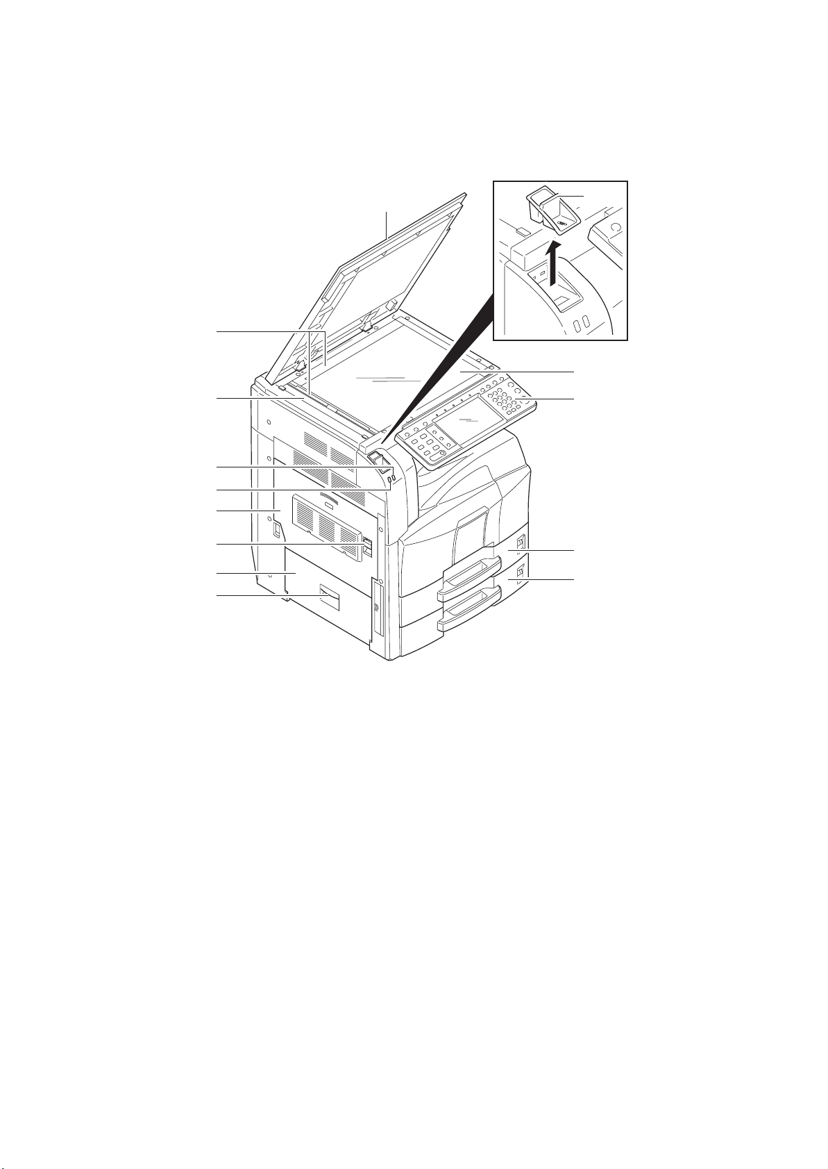
1-1-2 Parts names
(1) Machine
10
1
2
4
5
6
7
8
9
3
11
12
13
14
1-1-4
Figure 1-1-1
1. Original cover (option)
2. Original size indicator plates
3. Clip holder
4. Slit glass
5. Attention indicator
6. Receive indicator
7. Left cover 1
8. Left cover 1 lever
9. Left cover 2
10. Left cover 2 handle
11. Contact glass
12. Operation panel
13. Cassette 1
14. Cassette 2
2KR/2KS
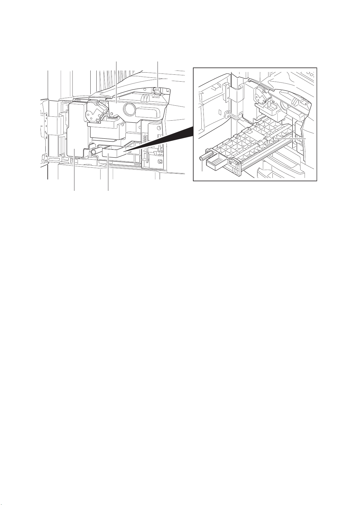
1516
19
20
17
18
Figure 1-1-2
15. Toner container stopper
16. Toner container
17. Waste toner box
18. Paper feed unit (A2)
19. Paper feed unit cover (A3)
20. Knob
1-1-5
2KR/2KS
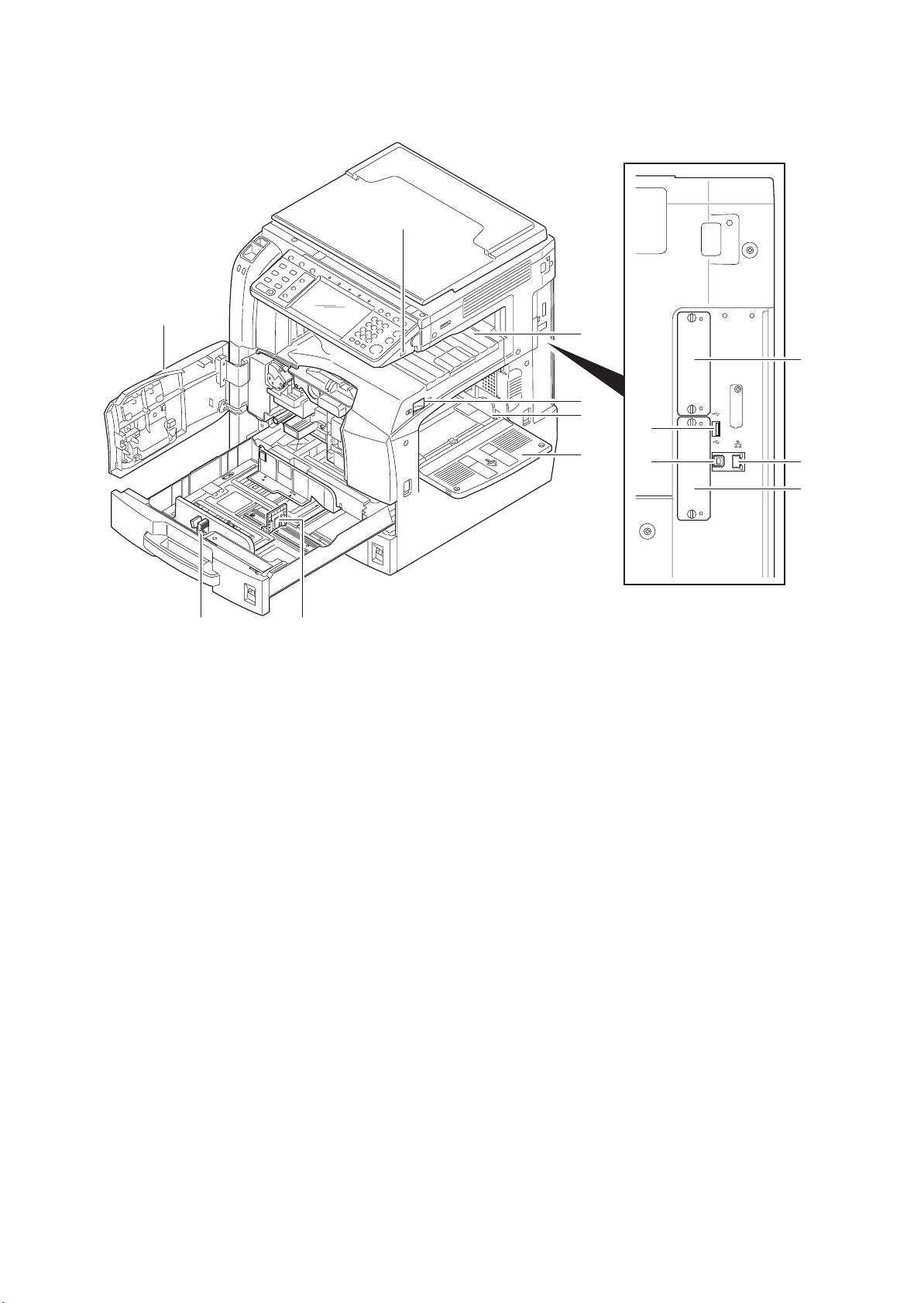
21
22
23 24
Figure 1-1-3
21. USB memory slot (A1)
22. Front cover
23. Paper width adjusting tab
24. Paper length guide
25. Top tray
26. Main power switch
27. Paper width guide
28. MP tray (multi purpose tray)
29. Optional interface slot (OPT2)
30. USB memory slot (A2)
31. USB interface connector (B1)
32. Network interface connector
33. Optional interface slot (OPT1)
25
26
27
28
30
31
OPT2
29
DP
A2
B1
32
33
OPT1
1-1-6
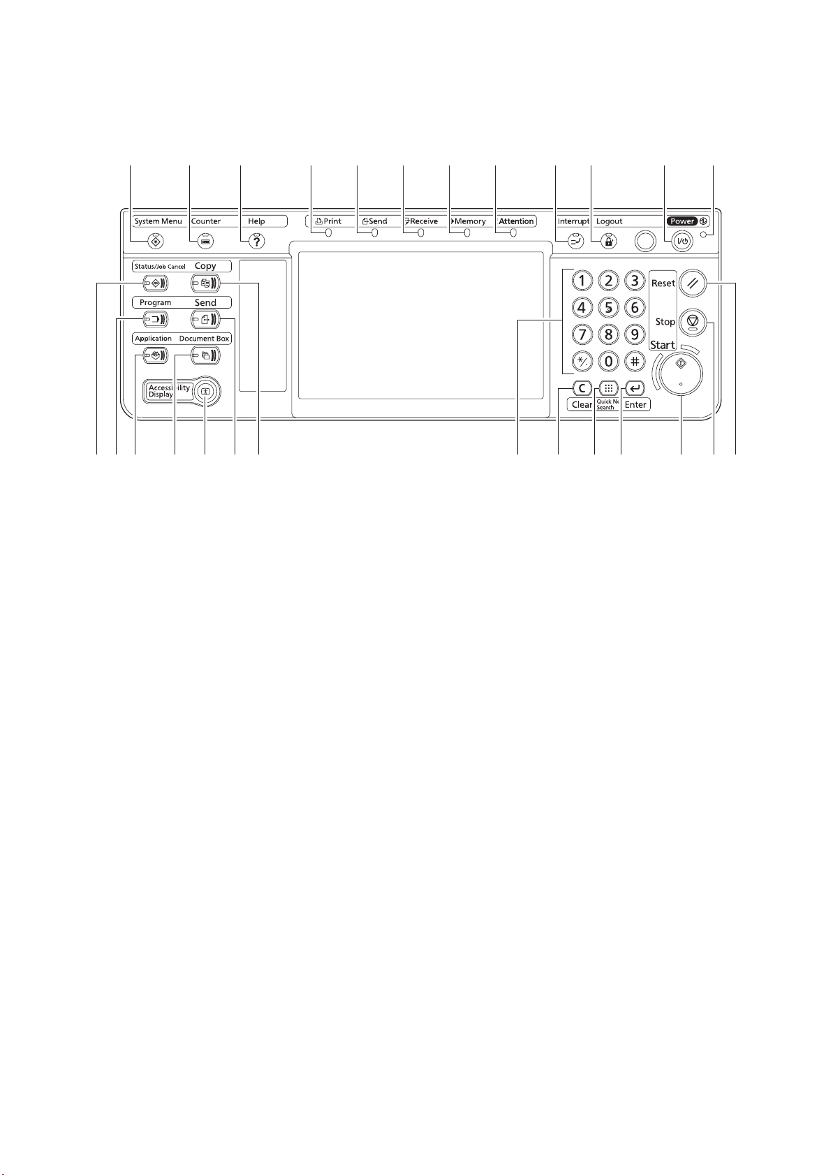
(2) Operation panel
2KR/2KS
1
15 16 17 18 19 20 21 22 23 24 25 26
13 14
2 3 45678 910 1112
Figure 1-1-4
1. System menu key/indicator
2. Counter key/indicator
3. Help key/indicator
4. Print indicator
5. Send indicator
6. Receive indicator
7. Memory indicator
8. Attention indicator
9. Interrupt key/indicator
10. Logout key/indicator
11. Power key/indicator
12. Main power indicator
13. Status/Job cancel key/indicator
14. Program key/indicator
15. Application key/indicator
16. Document box key/indicator
17. Accessibility key/indicator
18. Send key/indicator
19. Copy key/indicator
20. Numeric keys
21. Clear key
22. Quick No. search key
23. Enter key
24. Start key/indicator
25. Stop key
26. Reset key
1-1-7
2KR/2KS
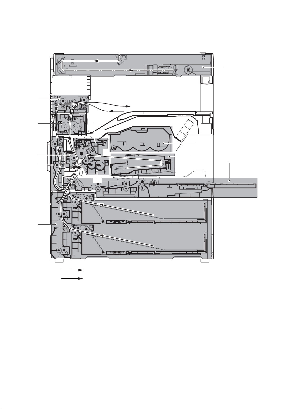
1-1-3 Machine cross section
10
3
11
9
5
7
8
4
2
6
1
1-1-8
Light path
Paper path
Figure 1-1-5 Machine cross section
1. Cassette paper feed section
2. MP tray paper feed section
3. Image scanner section
4. Laser scanner section
5. Drum section
6. Developing section
7. Toner container section
8. Transfer and separation sections
9. Fuser section
10. Eject and switchback sections
11. Duplex section
1-2 Installation
1-2-1 Installation environment
1. Temperature: 10 to 32.5°C/50 to 90.5°F
2. Humidity: 15 to 80%RH
3. Power supply: 120 V AC, 12 A
220 to 240 V AC, 6.3 A
4. Power source frequency: 50 Hz
5. Installation location
Avoid direct sunlight or bright lighting. Ensure that the photoconductor will not be exposed to direct sunlight or
other strong light when removing paper jams.
Avoid locations subject to high temperature and high humidity or low temperature and low humidity; an abrupt
change in the environmental temperature; and cool or hot, direct air.
Avoid places subject to dust and vibrations.
Choose a surface capable of supporting the weight of the machine.
Place the machine on a level surface (maximum allowance inclination: 1
Avoid air-borne substances that may adversely affect the machine or degrade the photoconductor, such as mercury, acidic of alkaline vapors, inorganic gasses, NOx, SOx gases and chlorine-based organic solvents.
Select a well-ventilated location.
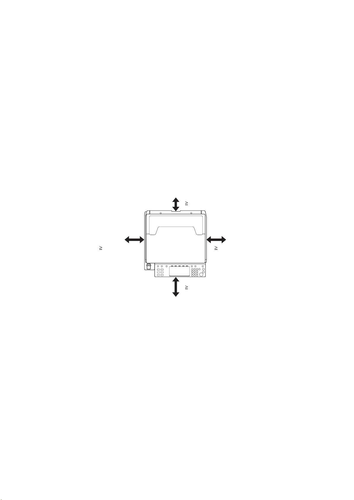
6. Allow sufficient access for proper operation and maintenance of the machine.
Machine front: 1000 mm/39
Machine right: 300 mm/11
± 0.3%/60 Hz ± 0.3%
°).
3/8" Machine rear: 100 mm/3 15/16"
13/16" Machine left: 300 mm/11 13/16"
2KR/2KS
100 mm/3
300 mm/11 13/16" 300 mm/11 13/16"
1000 mm/39
15/16"
3/8"
Figure 1-2-1 Installation dimensions
1-2-1
2KR/2KS
1-2-2 Unpacking and installation
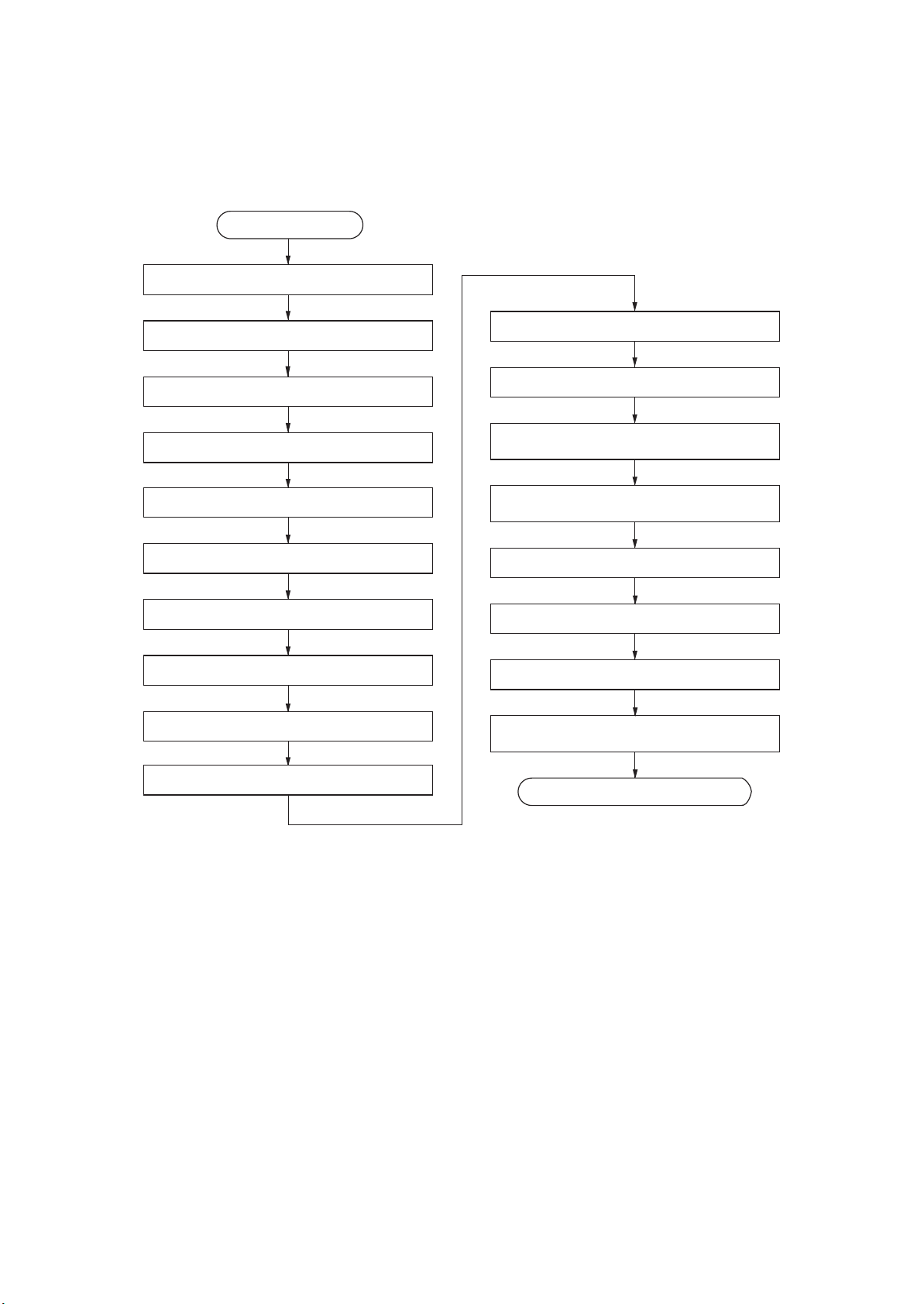
(1) Installation procedure
Start
Unpack.
Remove the tapes and pad.
Install the optional paper feeder.
Release the lever holding mirror 1 and 2 frames.
Release of cassette lift plate.
Load paper.
Install the toner container.
Install the waste toner box.
Install the optional original cover or the DP.
Connect the power cord.
Installing toner.
Setting the delivery date
(maintenance item U278).
Output an own-status report
(maintenance item U000).
Exit maintenance mode.
Print out the user setting list.
Make test copies.
Attaching the language label
(230 V specifications only).
1-2-2
Install other optional devices.
Completion of the machine installation.

Moving the machine
When moving the machine, pull out the four handles on the right and left sides and hold them.
2KR/2KS
P
D
2
A
1
B
1
T
P
O
Handle
Handle
Handle
Handle
Figure 1-2-2
1-2-3
2KR/2KS-2
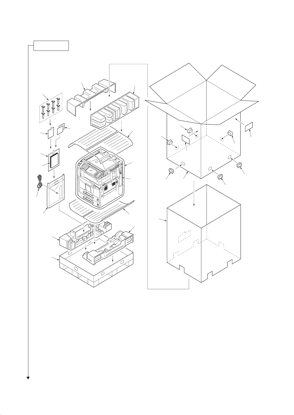
Unpacking.
16
12
13
14
17
11
15
7
8
9
18
18
19
18
19
10
1
18
2
18
18
9
3
6
5
4
Figure 1-2-3 Unpacking
1. Machine
2. Outer case
3. Inner frame
4. Skid
5. Bottom left pad
6. Bottom right pad
7. Upper left pad
8. Upper right pad
9. Sheets
10. Machine cover
Caution: Place the machine on a level surface.
11. Document tray
12. Power cord
13. Plastic bag
14. Operation guide
15. Paper size plates
16. Plastic bag
17. Cursor pins
18. Hinge joints
19. Bar code labels
1-2-4
Remove the tapes and pad.
1. Remove two tapes.
2. Remove the pad.
Pad
2KR/2KS
DP
A2
B1
OPT1
Install the optional paper feeder.
1. Install the optional paper feeder as necessary.
2. Verify levelness at the four corners of the platen using a level gauge, and
adjust the level bolts at the bottom of the machine to optimize levelness.
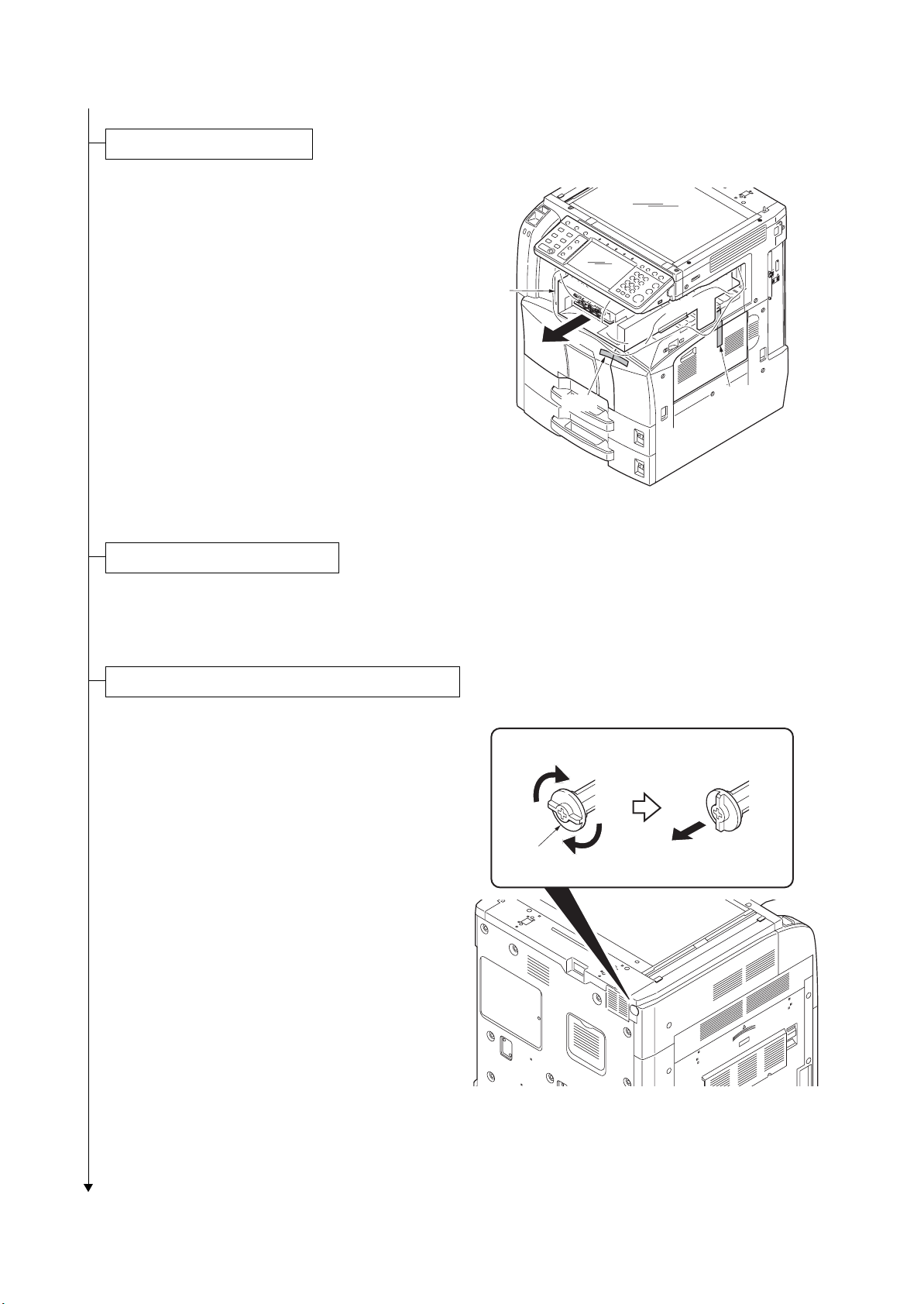
Release the lever holding mirror 1 and 2 frames.
1. Turn the lever of the machine rear side with
the tool to release the lever holding the mirror 1 and 2 frames.
Ta pe
Figure 1-2-4
Ta pe
Lever
Figure 1-2-5
1-2-5
2KR/2KS
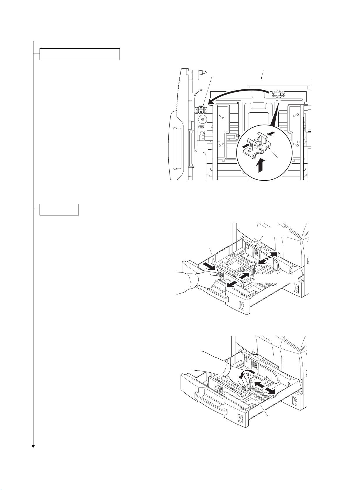
Release of cassette lift plate.
1. Pull cassette 1 and 2 out.
Remove the lift plate stopper from each cassette and attach it to the storage location.
When moving the machine, attach the lift
plate in original position.
Load paper.
1. Pull the cassette out.
2. Holding the paper width adjusting tab both
ends, move the paper width guides to fit the
paper size.
Lift plate stopper
Paper width
adjusting tab
Cassette
Lift plate
stopper
Figure 1-2-6
Paper width guide
3. Adjust the length adjustment plate to fit the
paper size.
Paper width guide
Figure 1-2-7
Length adjustment plate
Figure 1-2-8
1-2-6

4. Align the paper flush against the left side of
the cassette.
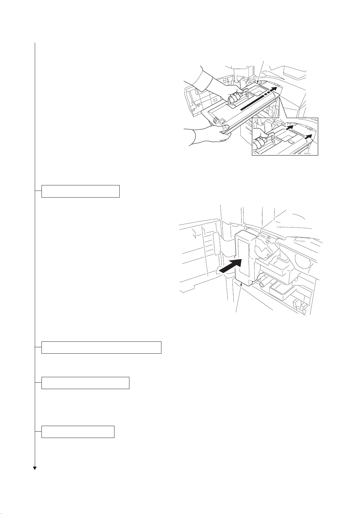
Install the toner container.
2KR/2KS
Figure 1-2-9
1. Open the front cover.
2. Tap the top of the toner container five to six
times.
3. Shake the toner container approximately 10
times in the horizontal direction to stir toner.
Toner container
Figure 1-2-10
Toner container
Figure 1-2-11
1-2-7
2KR/2KS
4. Gently push the toner container into the
machine along the rails.
Push the container all the way into the
machine until it locks in place.
Install the waste toner box.
Toner container
Figure 1-2-12
1. Install the waste toner box in the machine.
2. Close the front cover.
Install the optional original cover or the DP.
1. Install the optional original cover or DP.
Install other optional devices.
Waste toner box
Figure 1-2-13
1. Install the optional devices (job separator,
built-in finisher, document finisher and/or fax
kit etc.) as necessary.
Connect the power cord.
1. Connect the power cord to the connector on the machine.
2. Insert the power plug into the wall outlet.
1-2-8
 Loading...