

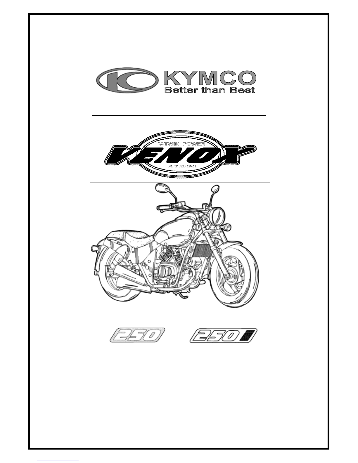
KYMCO Venox 250, Venox 250i Service Manual
SERVICE MANUAL
Overseas Sales Division
Overseas Service Department
VENOX 250/250i
By KWANG YANG Motor Co., Ltd.
First Edition, Dec 2006
All rights reserved. Any reproduction or
unauthorized use without the written permission of
KWANG YANG Motor Co., Ltd.
is expressly prohibited.
T100RB50AA
VENOX 250/250i
PREFACE
This Service Manual describes the technical features and servicing
procedures for the KYMCO VENOX 250/250 i.
In this manual, many illustrations and drawings are used to help
servicemen have better understanding.
Section 2 contains the service precautions for all operations and
troubleshooting stated in this manual. Read them carefully before starting
any operation.
Section 3 describes the inspection/adjustment procedures, safety rules and
service information for each part, starting from periodic maintenance.
Sections 4 through 18 give instructions for disassembly, assembly and
inspection of engine, chassis frame and electrical equipment.
Most sections start with an assembly or system illustration and
troubleshooting for the section. The subsequent pages give detailed
procedures for the section.
*
The information, specifications, and
illustrations included in this manual
may be different from the motorcycle
in case specifications are changed.

VENOX 250/250i
TABLE OF CONTENTS
GENERAL INFORMATION......................................................................... 1
INSPECTION/ADJUSTMENT...................................................................... 2
LUBRICATION SYSTEM............................................................................. 3
FUEL SYSTEM............................................................................................... 4
ENGINE REMOVAL/INSTALLATION...................................................... 5
CYLINDER HEAD/VALVES........................................................................ 6
CRANKSHAFT/PISTON/CYLINDER......................................................... 7
GENERATOR/LEFT CRANK CASE COVER........................................... 8
CLUTCH/GEAR SHIFT MECHANISM...................................................... 9
TRANSMISSION S Y ST E M...........................................................................10
COOLING SYSTEM ......................................................................................11
FRONT WHEEL/SUSPENSION/STEERING.............................................12
REAR WHEEL/BRAKE/SUSPENSION......................................................13
HYDRAULIC BRAKE ...................................................................................14
IGNITION SYSTEM ......................................................................................15
CHARGING SYSTEM ...................................................................................16
STARTING SYSTEM.....................................................................................17
LIGHTS/INSTRUMENT/SWITCHES/HORN............................................18
AFI(AUTOMATIC FUEL INJECTION) .....................................................19

1. GENERAL INFORMATION
1-0
VENOX250/250i
1
__________________________________________________________________________________
1
__________________________________________________________________________________
__________________________________________________________________________________
__________________________________________________________________________________
__________________________________________________________________________________
GENERAL INFORMATION
__________________________________________________________________________________
ENGINE SERIAL NUMBER/IDENTIFICATION............................. 1- 1
SPECIFICATIONS .............................................................................. 1- 2
SERVICE PRECAUTIONS................................................................. 1- 3
SERVICE INFORMATION ................................................................ 1-10
TORQUE VALUES............................................................................. 1-12
SPECIAL TOOLS................................................................................ 1-14
LUBRICATION POINTS.................................................................... 1-16
WIRING DIAGRAM........................................................................... 1-17
CABLE & HARNESS ROUTING....................................................... 1-18
TROUBLESHOOTING ....................................................................... 1-22
1. GENERAL INFORMATION
1-1
VENOX250/250i
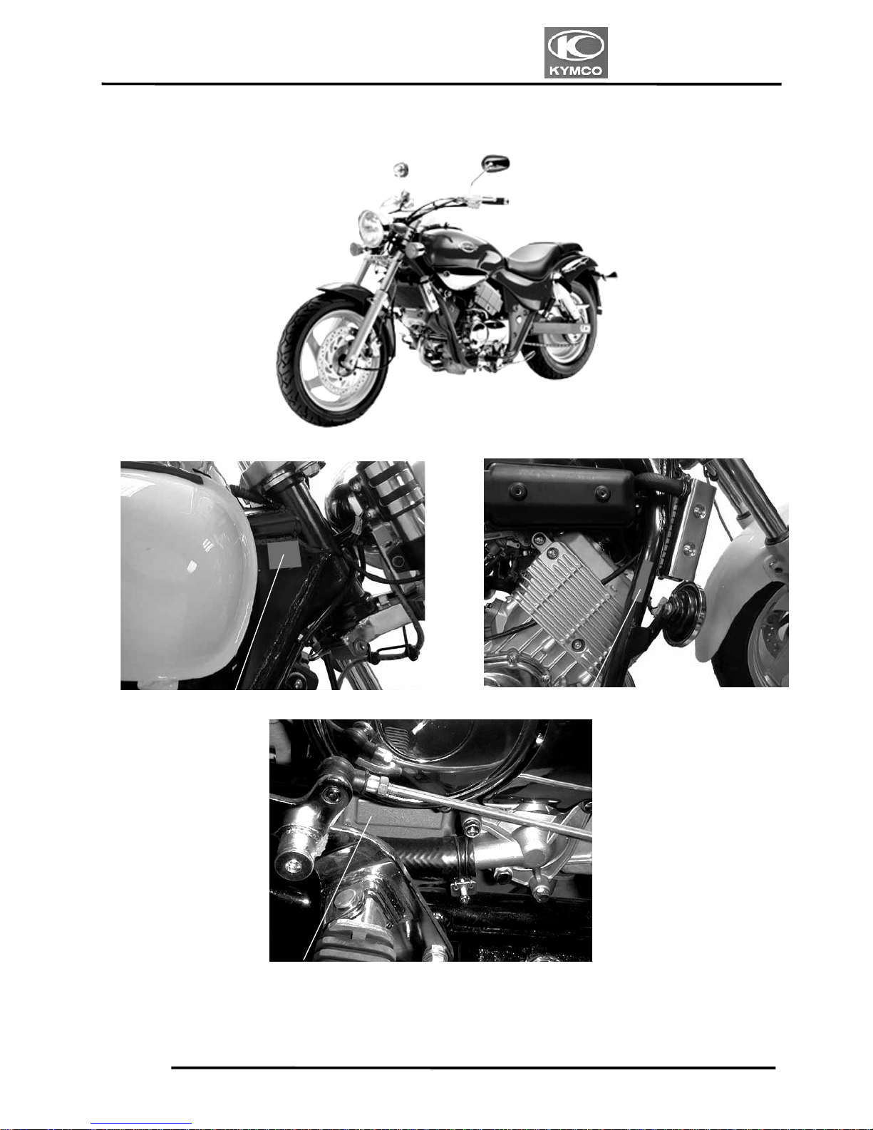
ENGINE SERIAL NUMBER/IDENTIFICATION
Location of Frame Serial Numbe
r
Vehicle Identification Serial Numbe
r
Location of Engine Serial Numbe
r
1. GENERAL INFORMATION
1-2
VENOX250/250i
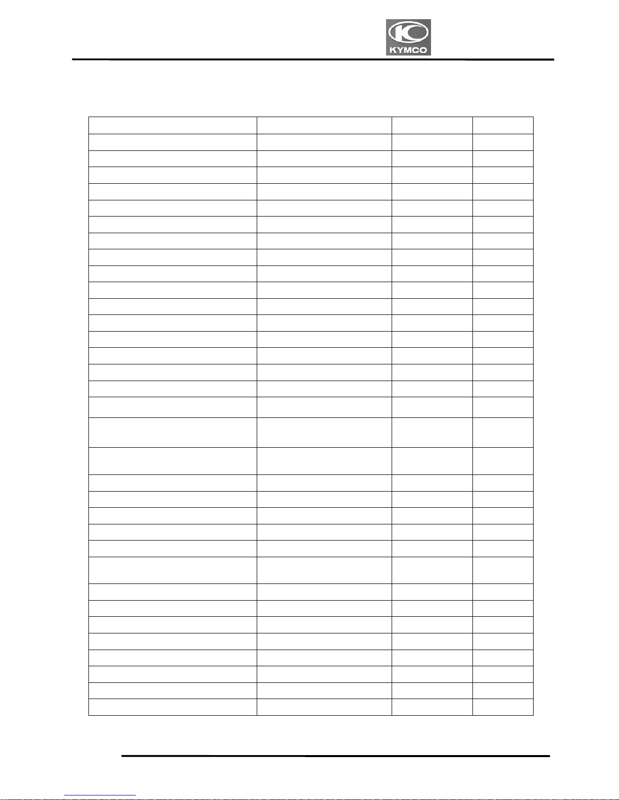
SPECIFICATIONS
Model No. RA50AA
Motorcycle name VENOX 250
Overall length (mm) 2325
Overall width (mm) 850
Overall height (mm) 1100
Wheel base (mm) 1600
Engine type 4 f
Displacement (cc) 249.4
Fuel type 92/95# nonleaded gasoline
Front wheel 82
Rear wheel 101
Dry weight (kg)
Total 183
Front wheel 90
Rear wheel 109
Gross weight(kg)
Total 199
Front wheel 120/80-17
Tires
Rear wheel 150/80-15
Ground clearance (mm) 150
Starting system
Starting motor
Type DOHC
Cylinder arrangement cylinder
Combustion chamber type Semi-sphere
Valve train DOHC-8V
Bore x stroke (mm) 58x 47.2
Compression ratio 11
Compression pressure
(kg/cm²)
17
Max. output (ps/rpm) --Max. torque (Kg.m/rpm) ---
Open 4˚
Intake
(mm)
Close 35˚
Engine
Open 31˚
Port
timing
Exhaust
(mm)
Close 0˚
Intake 0.10mm
Valve clearance
(cold)
Exhaust 0.10mm
Idle speed (rpm) 1300rpm
Lubrication type
Forced pressure &
wet sump
Oil pump type Inner/outer rotor
Oil filter type Wire gauze filter
Lubrication
System
Oil capacity 2.5L
Cooling Type Air +water cooling
Air cleaner type Paper element type
Fuel capacity 14liter
Type CVK
Main Jet NO Front:110 Rear:108
Venturi dia.(mm) I30 equivalent
Carburetor
Throttle type Butterfly type
Type CDI
Ignition timing B.T.D.C10° / 1000rpm
Spark plug NGK-CR8E
Ignition
System
Spark plug gap 0.6阡0.7mm
Electrical
Equipment
Battery Capacity 12V8AH
Clutch Type Wet multi-disc clutch
Type 5-Speed transmission
Operating method Foot operated
Type International type
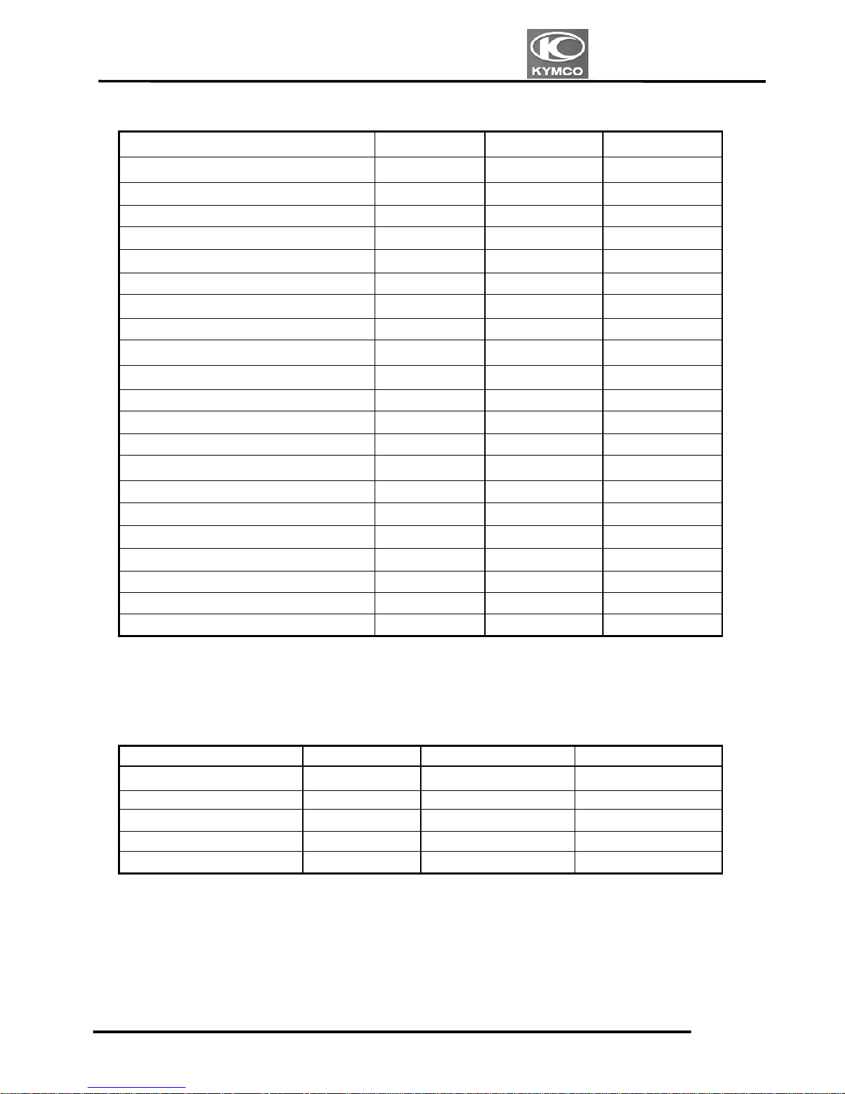
1st gear 2.773
2nd gear 1.8
3rd gear 1.375
4th gear 1.111
Transmission Gear
Reduction
ratio
5th gear 0.965
Front 2.0
Fuel S
y
stem
Power Drive S
y
stem
(kg/cm²)(2 riders)
Rear 2.25
Left 40q
Turning angle
Right 40q
Front Disk brake
Moving
Device
Brake system type
Rear Drum brake
Front Oil damper spring
Damping
Device
Suspension
Rear Oil damper spring
Frame type Double cradle
VENOX AFI
Air cleaner type Paper element
Fuel capacity 14 liter
Type FUEL INJECTION
SYSTEM
Fuel System
THROTTL
E BODY
SIZE OFF
BORE(mm)
I32
Type Fully Transistor
Ignition timing B.T.D.C10q/1300rpm
Breaker type
Spark plug
CR8E
Ignition System
Spark plug gap 0.6阡0.7mm
Electrical Equipment
Battery Capacity 12V8AH
1. GENERAL INFORMATION
1-3
VENOX250/250i
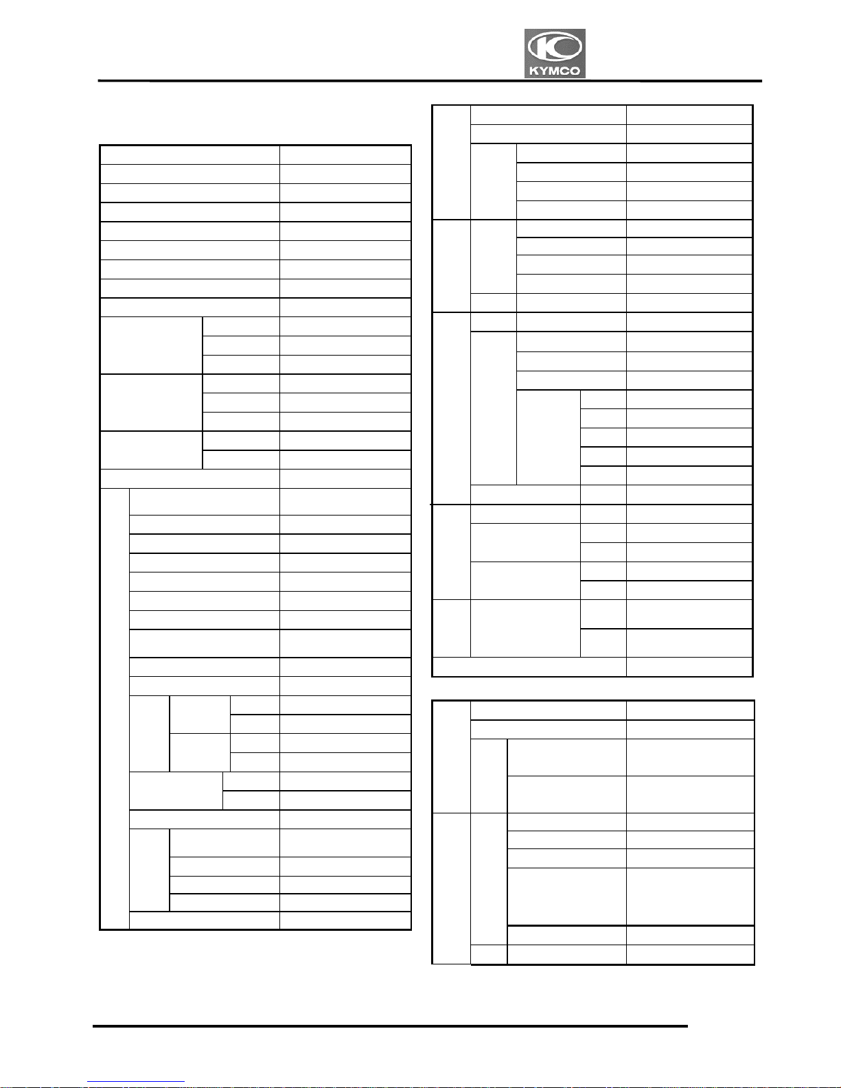
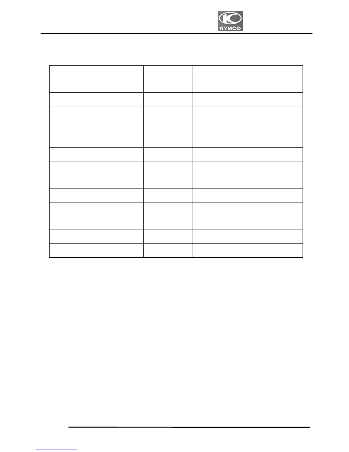
SERVICE PRECAUTIONS
Make sure to install new gaskets, O-rings,
circlips, cotter pins, etc. when reassembling.
When tightening bolts or nuts, begin with
larger-diameter to smaller ones at several
times, and tighten to the specified torque
diagonally.
Use genuine parts and lubricants.
When servicing the motorcycle, be sure to
use special tools for removal and
installation.
After disassembly, clean removed parts.
Lubricate sliding surfaces with engine oil
before reassembly.
1. GENERAL INFORMATION
1-4
VENOX250/250i
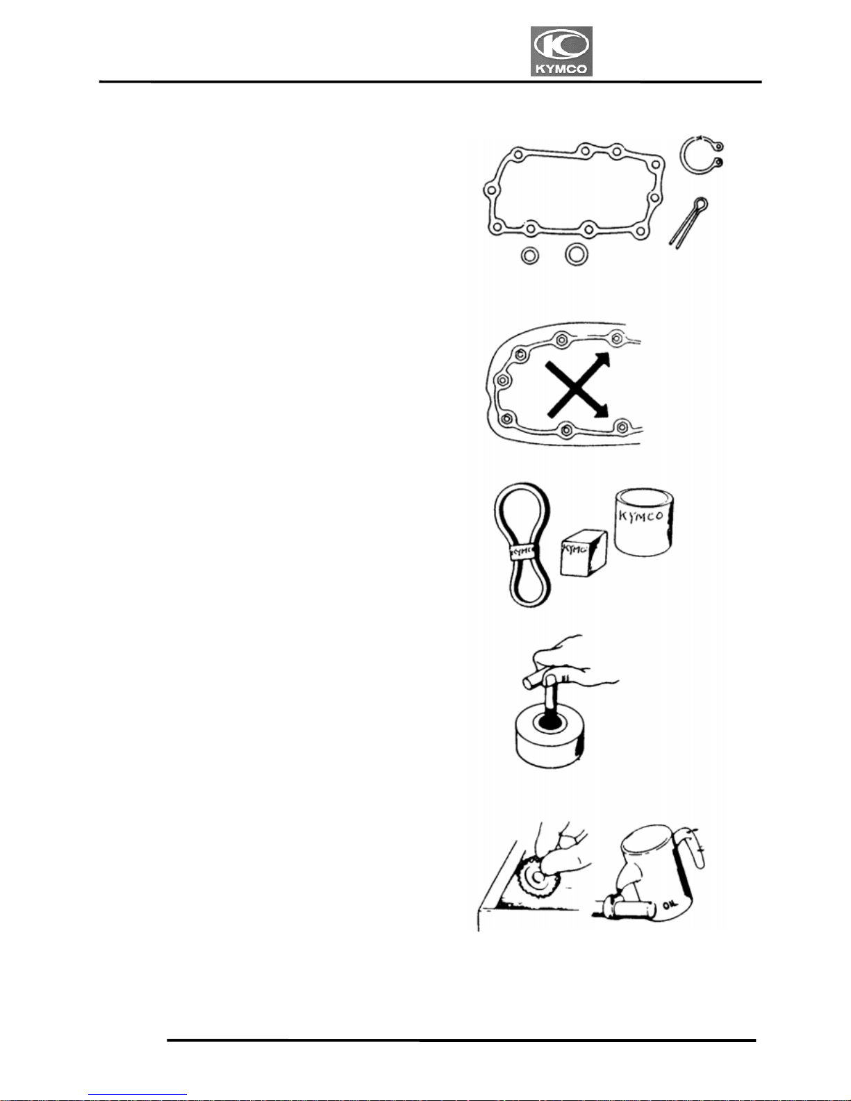
Apply or add designated greases and
lubricants to the specified lubrication
points.
After reassembly, check all parts for proper
tightening and operation.
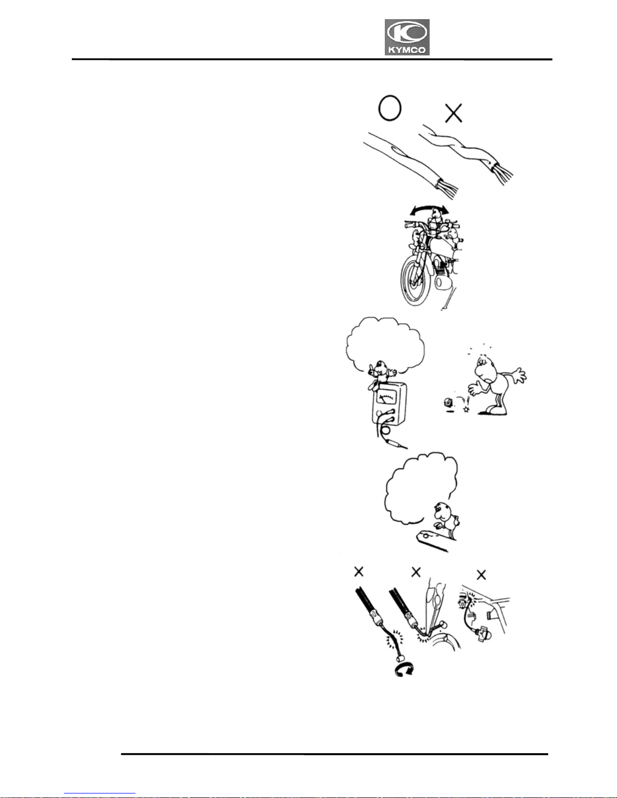
When two persons work together, pay
attention to the mutual working safety.
Disconnect the battery negative (-) terminal
before operation.
When using a spanner or other tools, make
sure not to damage the motorcycle surface.
After operation, check all connecting
points, fasteners, and lines for proper
connection and installation.
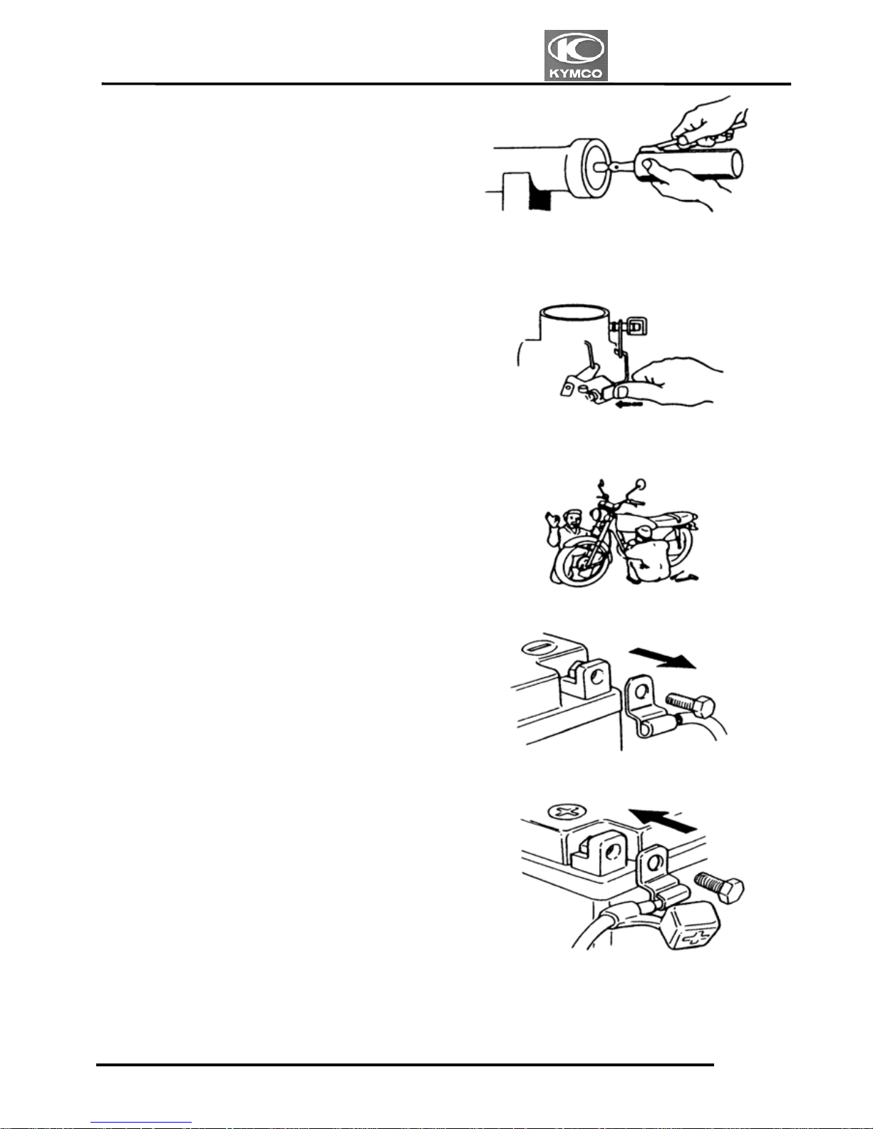
When connecting the battery, the positive
(+) terminal must be connected first.
After connection, apply grease to the
battery terminals.
Terminal caps shall be installed securely.
1. GENERAL INFORMATION
1-5
VENOX250/250i
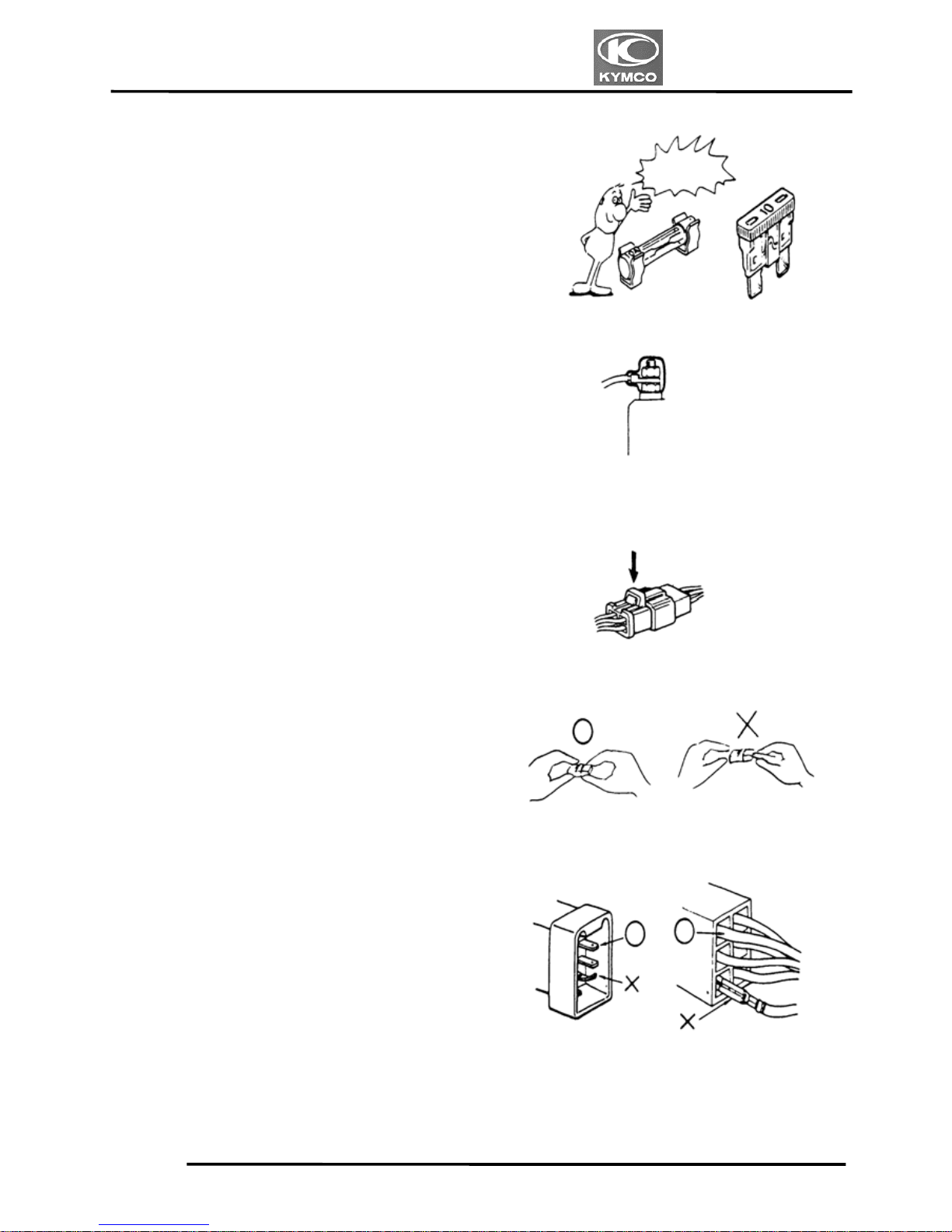
If the fuse is burned out, find the cause and
repair it. Replace it with a new one
according to the specified capacity.
After operation, terminal caps shall be
installed securely.
When taking out the connector, the lock on
the connector shall be released before
operation.
Hold the connector body when connecting
or disconnecting it.
Do not pull the connector wire.
Check if any connector terminal is bending,
protruding or loose.
Conf
irm
Capacity
1. GENERAL INFORMATION
1-6
VENOX250/250i
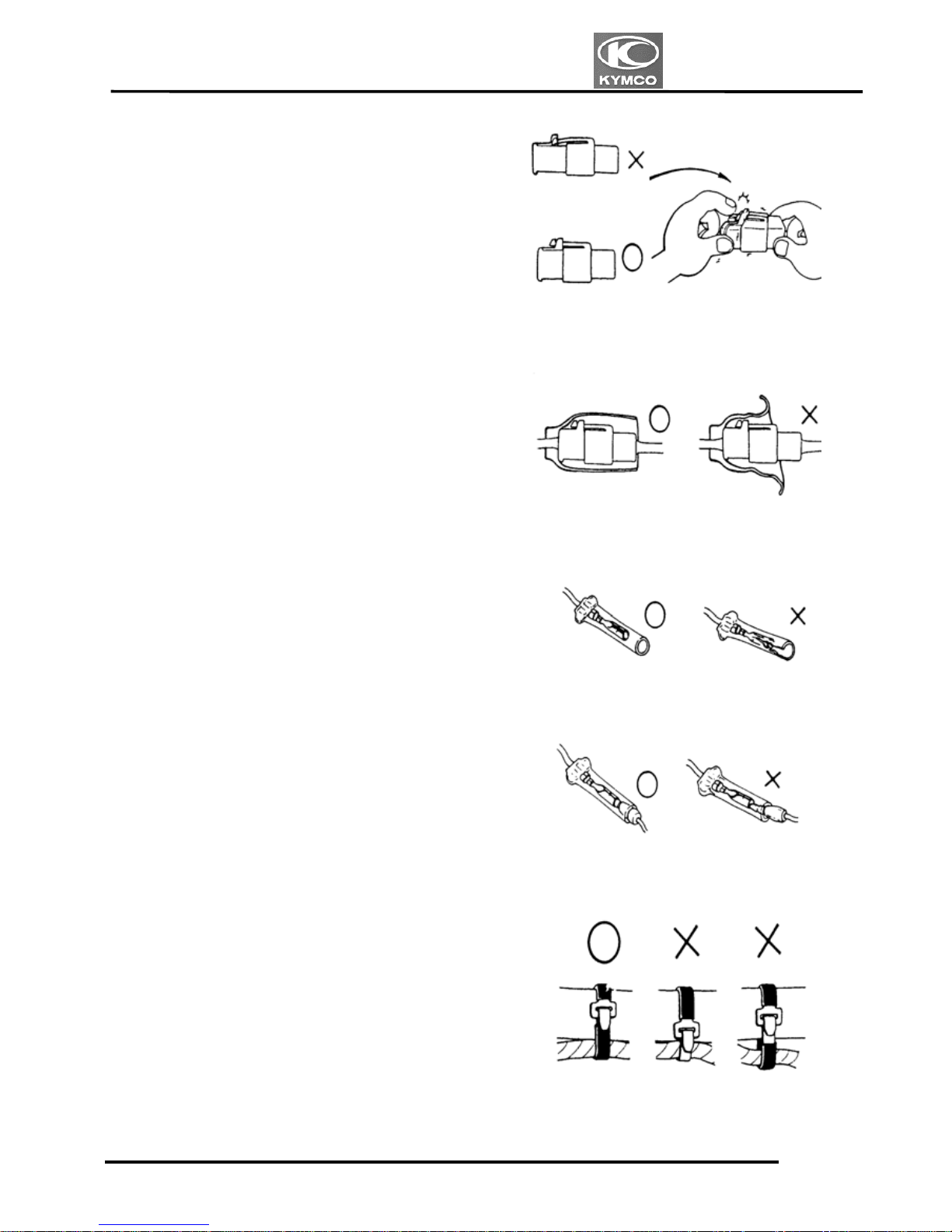
The connector shall be inserted
completely.
If the double connector has a lock, lock
it at the correct position.
Check if there is any loose wire.
Check the double connector cover for
proper coverage and installation.
Before connecting a terminal, check for
damaged terminal cover or loose
negative terminal.
Insert the terminal completely.
Check the terminal cover for proper
coverage.
Do not make the terminal cover opening
face up.
Secure wire harnesses to the frame with
their respective wire bands at the
designated locations.
Tighten the bands so that only the insulated
surfaces contact the wire harnesses.
Snapping
1. GENERAL INFORMATION
1-7
VENOX250/250i
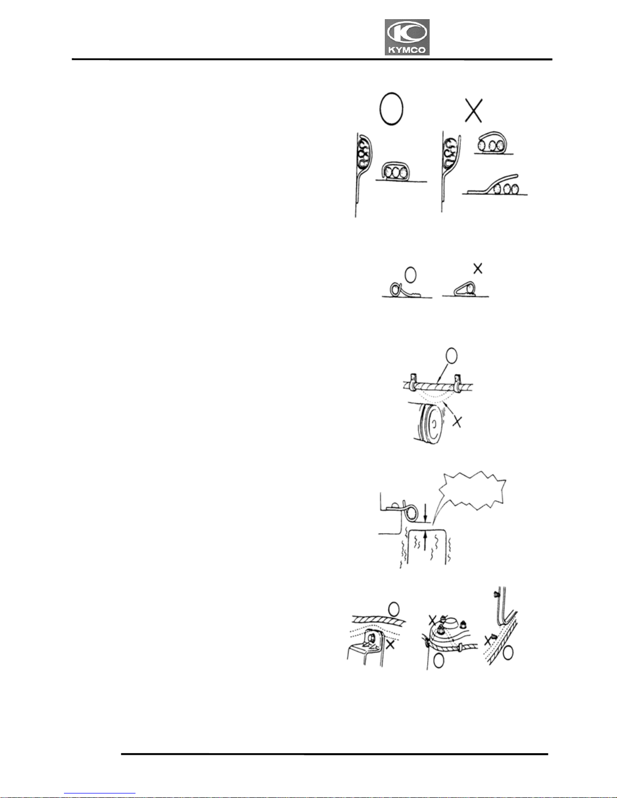
After clamping, check each wire to make
sure it is secure.
Do not squeeze wires against the weld or
its clamp.
After clamping, check each harness to
make sure that it is not interfering with any
moving or sliding parts.
When fixing the wire harnesses, do not
make it contact the parts which will
generate high heat.
Route wire harnesses to avoid sharp edges
or corners. Avoid the projected ends of
bolts and screws.
Route wire harnesses passing through the
side of bolts and screws. Avoid the
projected ends of bolts and screws.
No Contact !
1. GENERAL INFORMATION
1-8
VENOX250/250i
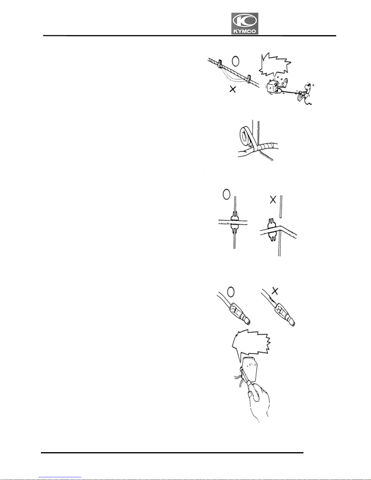
Route harnesses so they are neither
pulled tight nor have excessive slack.
Protect wires and harnesses with electrical
tape or tube if they contact a sharp edge or
corner.
When rubber protecting cover is used to
protect the wire harnesses, it shall be
installed securely.
Do not break the sheath of wire.
If a wire or harness is with a broken sheath,
repair by wrapping it with protective tape
or replace it.
When installing other parts, do not press or
squeeze the wires.
Do not
pull too
ti
g
ht!
Do not press
or squeeze
the wire.
1. GENERAL INFORMATION
1-9
VENOX250/250i
After routing, check that the wire harnesses
are not twisted or kinked.
Wire harnesses routed along with
handlebar should not be pulled tight, have
excessive slack or interfere with adjacent
or surrounding parts in all steering
positions.
When a testing device is used, make sure to
understand the operating methods
thoroughly and operate according to the
operating instructions.
Be careful not to drop any parts.
When rust is found on a terminal, remove
the rust with sand paper or equivalent
before connecting.
Do not bend or twist control cables.
Damaged control cables will not operate
smoothly and may stick or bind.
Do you understand
the instrument? Is
the instrument set
correctly?
Remove
rust !
1. GENERAL INFORMATION
1-10
VENOX250/250i
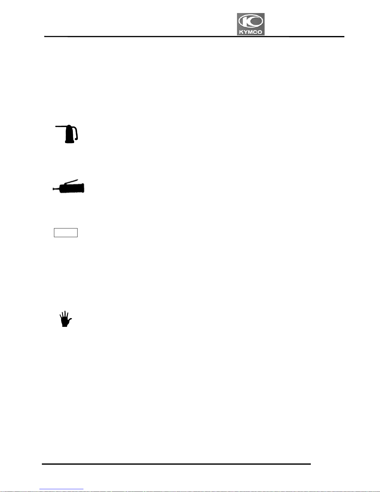
Symbols:
The following symbols represent the
servicing methods and cautions included in
this service manual.
: Apply engine oil to the
specified points. (Use the
designated engine oil for
lubrication.)
Engine Oil
: Apply grease for lubrication.
: Use special tool.
: Caution
:Warning
Grease
Special
*
1. GENERAL INFORMATION
1-11
VENOX250/250i
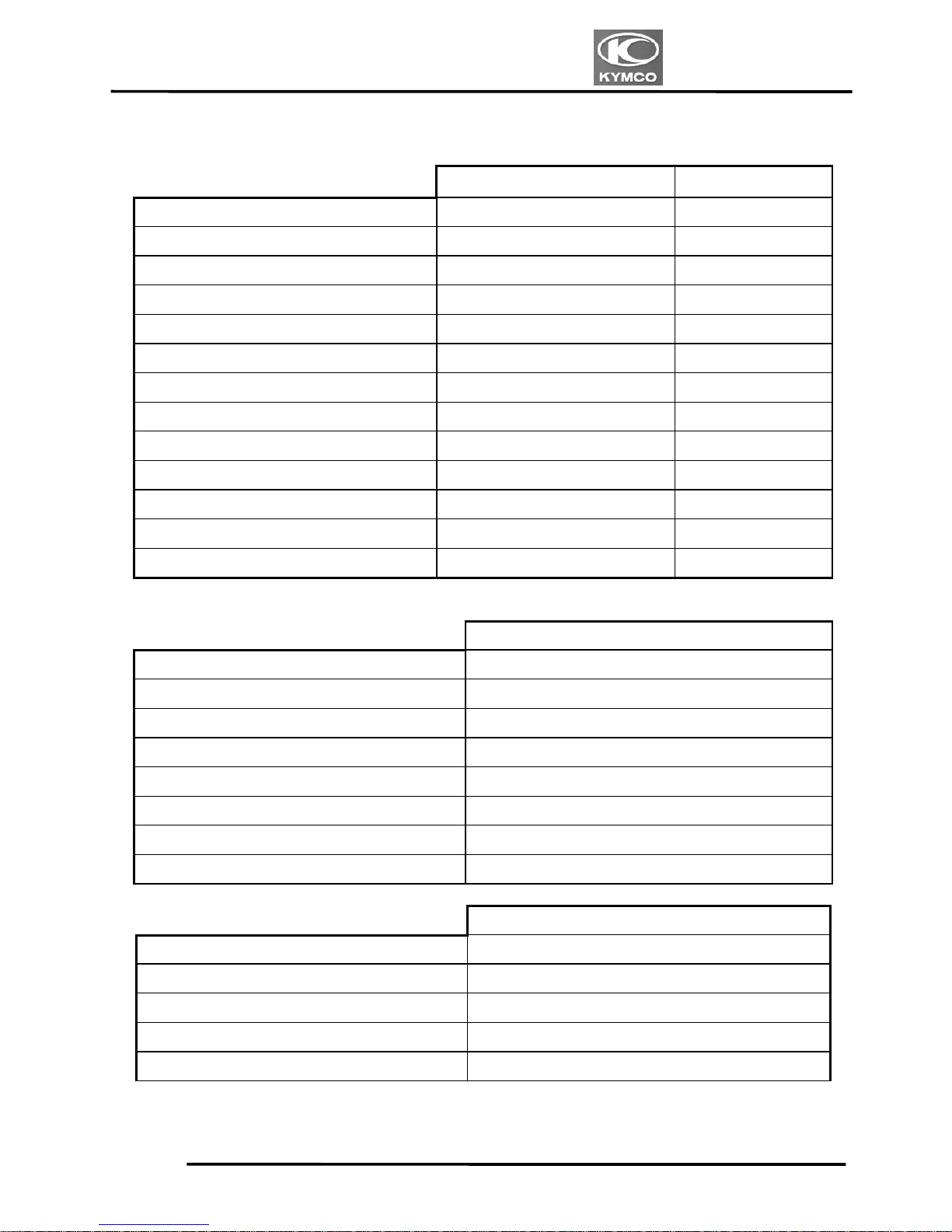
SERVICE INFORMATION
ENGINE
Standard (mm) Service Limit (mm)
Item
Venox 250 Venox 250
Cylinder head warpage
Piston O.D.(10mm from bottom of piston skirt)
57.975阡57.99 57.81
Cylinder-to- piston clearance
0.01阡0.35 0.35
Piston pin hole I.D.
16.000阡16.006 16.06
Piston pin O.D.
15.994阡15.997 15.90
Piston-to-piston pin clearance
0.003阡0.012 0.10
Piston ring end gap (top/second)
No1:0.10阡0.25 No2: 0.2阡0.35 0.5
Connecting rod small end I.D.
16.013阡16.028 16.09
Cylinder bore
58.0阡58.015 58.20
Connecting rod big end side clearance
0.09阡0.29
Connecting rod big end radial clearance
Crankshaft runout A/B
0.03
CARBURETOR
Venox 250
Venturi dia. 30 mm
Type CVK
Float level FR:17.5 mm RR:19.0mm
Main jet FR:#110 RR:#108
Slow jet #35
Pilot screw opening
2 3/8±½
Idle speed 1300±100 rpm
Throttle grip free play 2阡6mm
AFI
Venox 250i
THROTTLE BODY SIZE OF BORE 32mm
Type FUEL INJECTION SYSTEM
INJECTOR mm3/@24ms ; 82mm3/@24ms
FUEL PRESSURE 2.5 Bar REGULATOR
Idle speed 1300±100 rpm
1. GENERAL INFORMATION
1-12
VENOX250/250i
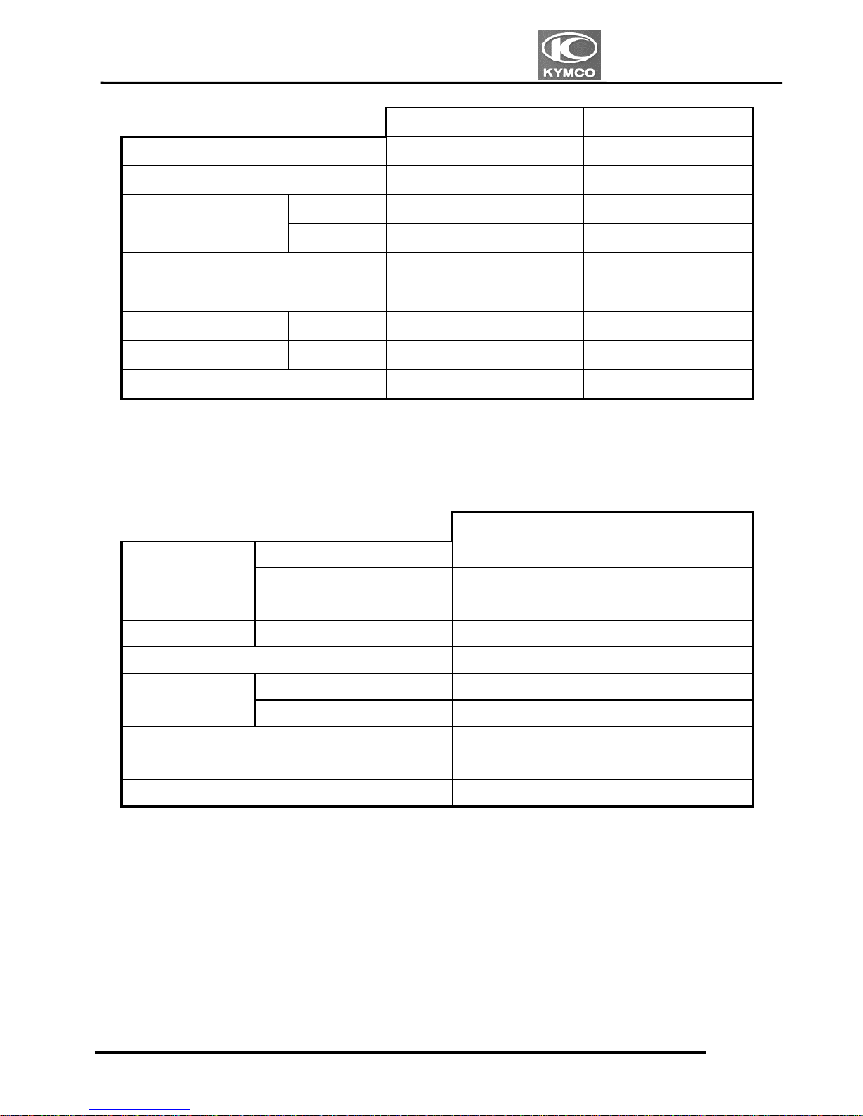
FRAME
Standard (mm) Service Limit (mm)
Item Venox 250 Venox 250
Axle shaft runout
0.3/100mm
0.5
Radial 0.5 2.0
Front wheel rim runout
Axial 0.5 2.0
Front shock absorber spring free length
Rear wheel rim runout 0.5 2.0
Brake drum I.D. Rear 160 161
Brake lining thickness Front/Rear 5.0/5.0 2.0/2.0
Rear shock absorber spring free length
ELECTRICAL EQUIPMENT
Venox 250
Capacity 12V8AH
Voltage 13.0阡13.2V
Battery
Charging current 0.9A/5阡10H
Spark plug (NGK) CR8E
Spark plug gap (mm) 0.6阡0.7
Primary
3.57阡4.83:
Ignition coil
resistance
Secondary (with plug cap)
14.96阡20.24K:
Pulser coil resistance (20℃) 396阡594:
Ignition timing
10q BTDC/1000rpm---VENOX
Ignition timing
10q BTDC/1300rpm---VENOX AFI
1. GENERAL INFORMATION
1-13
VENOX250/250i
TORQUE VALUES
ENGINE
Item Thread dia.(mm)
Torque (kg-m)
Remarks
Plate oil flowby M5x12 0.8阡1.2
Connect rod nut M7x0.75 2.0阡2.4
Oil drain M12x15 2.0阡3.0
Plate ball brg holder 6x12 0.8阡1.2
Drum gear shift 6x20 0.8阡1.2
hift fork comp 6x12 0.8阡1.2
Sw assy neutral 1.0阡1.4
Crank case
8x60/8x65/8x75/8x32 1.9阡2.3
6x35/6x85/6x60/6x40/6x30/6x90 1.0阡1.4
Case cooler tank pipe 6x20 0.8阡1.2
Oil seperator 6x20 0.8阡1.2
Sprocket oil pump nut
8
1.8阡2.3
Oil sump 6x25 0.8阡1.2
Motor assy starter 6x25 0.8阡1.2
Holder head (FR/RR)
8x151 3.0阡3.4
8x131/8x48/8x65
1.9阡2.3
Tension guide pivot
1.8阡2.2
Liter assy tension(FR/RR)
6x22
1.0阡1.4
Liter assy tensioner screw
pan(FR/RR)
6x6
0.35阡0.5
Guide unpper tensioner
6x12
0.8阡1.2
Head cover
6x30
0.8阡1.2
Clutch nut lock 20 5.5阡6.5
Clutch 6x22 0.8阡1.2
One way clutch socket bolt
8x12 7.5阡8.5
One way clutch socket bolt
UBS(LEFT)
10x35 0.8阡1.2
R cover 6x30
0.8阡1.2
Cover change
6x30 0.8阡1.2
Water pump 6x55.6x10
0.8阡1.2
A.C.G 10x35
7.5阡8.5
L cover 6x30.6x35
0.8阡1.2
Sprocket drive bolt special 10x30
5.5阡6.5
Spark plug CR8E
1.0阡1.4
Head bolt stud 6x40 0.7阡1.1
1. GENERAL INFORMATION
1-14
VENOX250/250i
FRAME
Item Thread dia.(mm) Torque (kg-m) Remarks
Strg stem nut
22x1.0 6.0阡8.0
Thread comp strg head 26x1.0 0.15阡2.5
Back 90°
Top bridge 8x1.25 1.7阡2.1
Bottom bridge 10x1.25 2.4阡3.0
Front axle bolt 14x1.5 6.0阡8.0
Rear axle nut 16x1.5 8.0阡10
Front brake caliper 8x1.25 2.4阡3.0
Oil bolt 10x1.25 3.0阡4.0
Master cylinder holder 6x1.0 0.8阡1.2
Rear suspension cush bolt (upper) 6x1.0 0.8阡1.2
Rear suspension cush bolt(under) 10x1.25 3.0阡4.0
Front suspension cush bolt(axle) 8x1.25 3.0阡4.0
Rear fork pivot nut 14x1.5 6.0阡8.0
Up ENG hanger 10x1.25 3.5阡4.5
Front ENG hanger 10x1.25 3.5阡4.5
8x1.25 2.4阡3.0
Rear ENG hanger 10x1.25 3.5阡4.5
Handle nut 12x1.25 5.0阡6.0
EXH Muffler bolt 8x1.25 3.0阡3.6
Front step bolt 10z1.25 3.0阡4.0
Rear winker 10x1.25 1.6阡1.8
Torque specifications listed above are for important fasteners. Others should be tightened to
standard torque values below.
STANDARD TORQUE VALUES SH bolt:8mm Flange bolt:6mm
Ite
m
Torque (kg-m
)
Ite
m
Torque (kg-m
)
5mm bolt, nut 0.45阡0.6 4.5mm screw 0.35阡0.5
6mm bolt, nut 0.8阡1.2 6mm nut, SH bolt 0.7阡1.1
8mm bolt, nut 1.8阡2.0 6mm flange bolt, nut 1.0阡1.4
10mm bolt, nut 3.0阡4.0 8mm flange bolt, nut 2.0阡3.0
12mm bolt, nut 5.0阡6.0 10mm flange bolt, nut 3.5阡4.5
1. GENERAL INFORMATION
1-15
VENOX250/250i
SPECIAL TOOLS
Tool Name Tool No. Remarks
Lock nut socket wrench E046 9-6
Lock nut wrench F006 12-11,12-12
Flywheel holder E021 8-3,8-4
Flywheel puller
E042
8-4
Valve wrench
E036
2-13
Vacuum & CO adjuster E043 2-14
Vacuum gauge
E045 2-14
Valve spring compressor E040 6-8,6-9
Piston installer E041 7-8
Clutch lifter holder E047 9-6
Bearing remover E030 10-10
Bearing driver handle E014 12-8,13-6
Steering stem wrench F007 12-11,12-12
1. GENERAL INFORMATION
1-16
VENOX250/250i
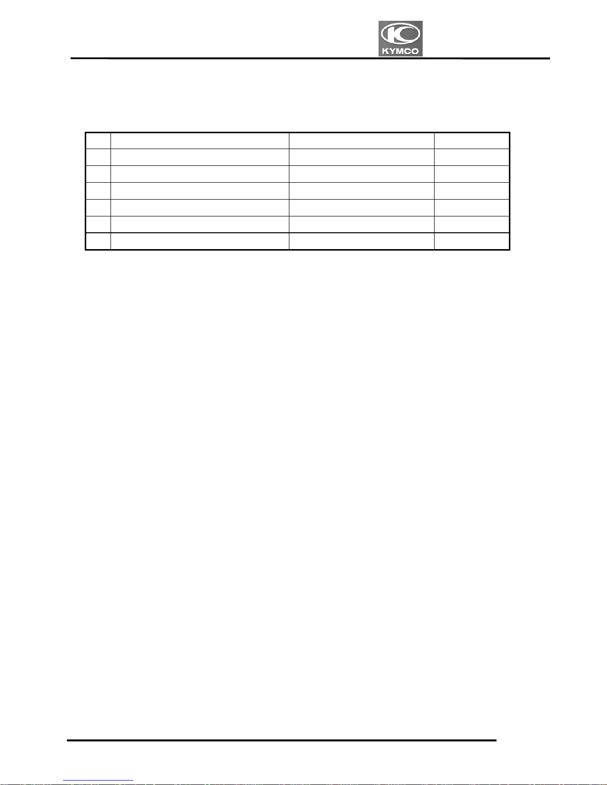
LUBRICATION POINTS
ENGINE
NO. Lubrication Points Lubricant Remarks
1 Crankcase sliding and movable parts SAE 5W-50 SF
2 Cylinder movable parts SAE 5W-50 SF
3 Drive chain SAE 80~90
4 Kick lever movable parts Grease
5 Front suspension SAE 10W 400cc/piece
6 Rear suspension SAE 5W 99cc/piece
FRAME
Apply clean engine oil or grease to cables and movable parts not specified. This will avoid
abnormal noise and rise the durability of the motorcycle.
1. GENERAL INFORMATION
1-17
VENOX250/250i
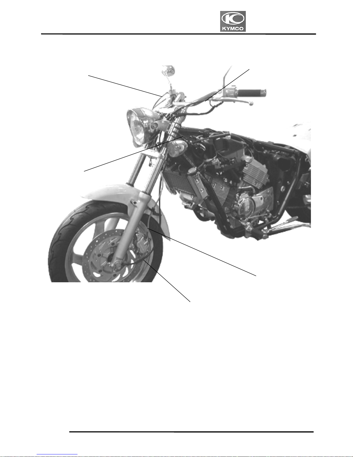
CABLE & HARNESS ROUTING
Clutch Cable
Throttle Cable
Front Brake
Speedometer Cable
Wire Harness
1. GENERAL INFORMATION
1-18
VENOX250/250i
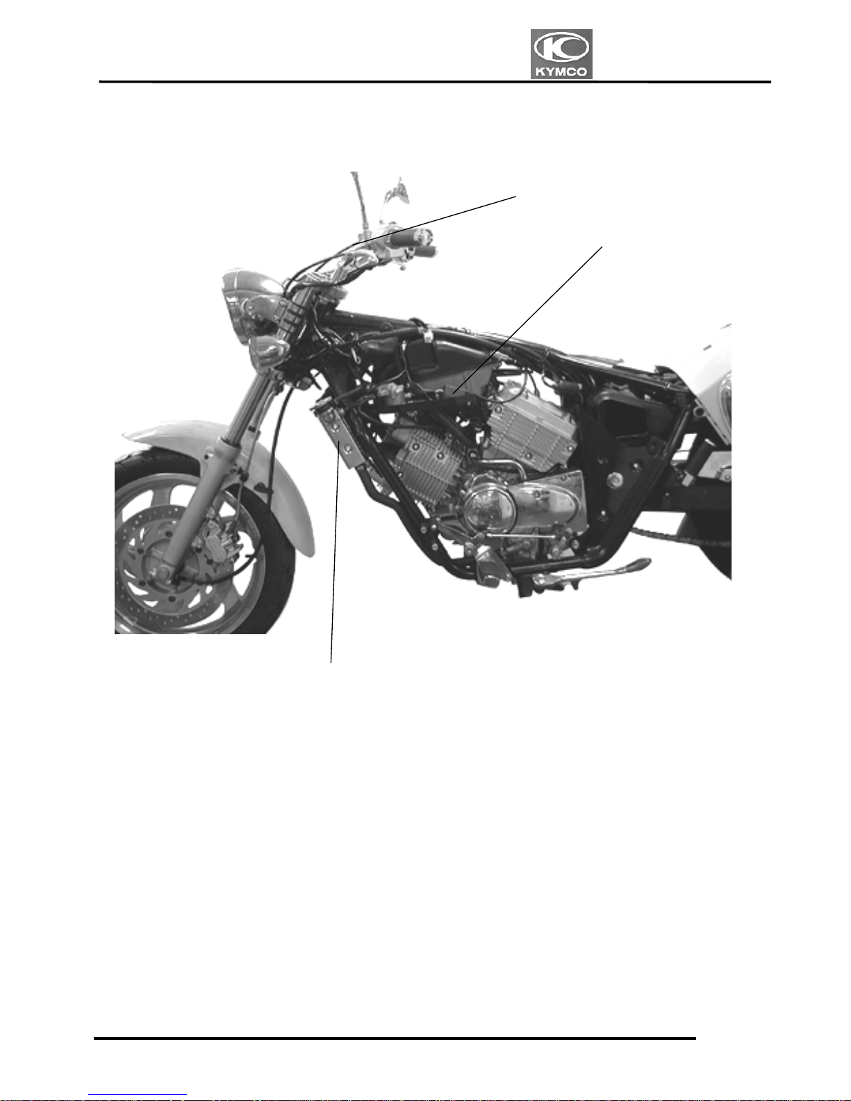
Throttle Cable
Radiato
r
Ignition Coil
1. GENERAL INFORMATION
1-19
VENOX250/250i
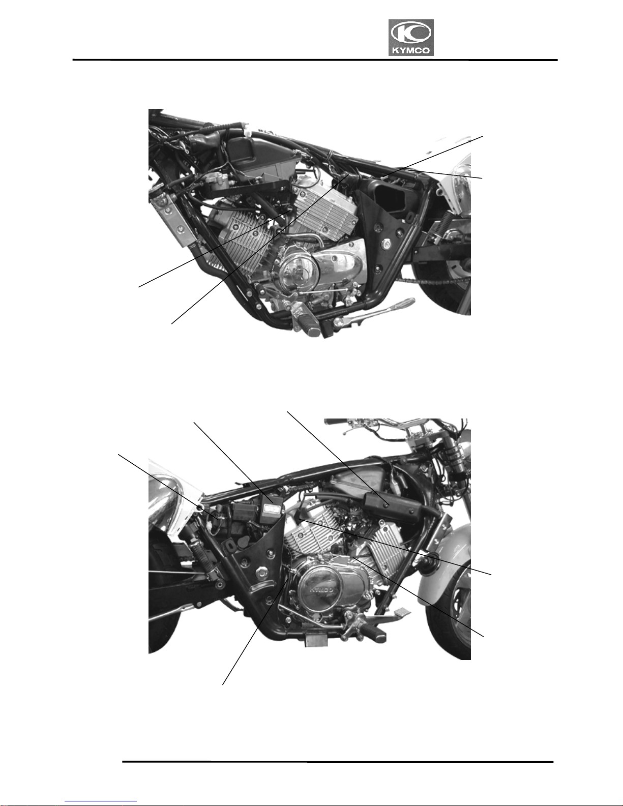
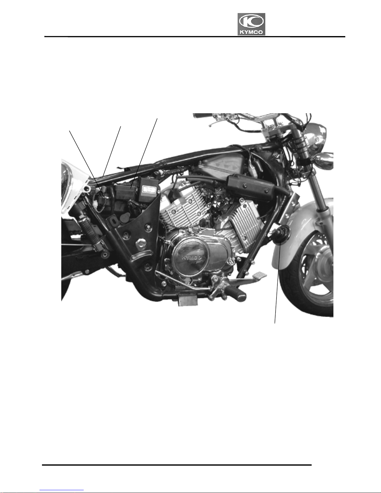
Choke Ro
d
Battery Negative
Terminal
Battery Positive
Terminal
A.C.G Cor
d
Clutch Cable
Air Cleane
r
Starter Relay
Spark Plug
Rear Stop Switch
Regulator/Rectifie
r
1. GENERAL INFORMATION
1-20
VENOX250/250i
Fuse
Battery
Starter Relay
Horn

1. GENERAL INFORMATION
1-21
VENOX250/250i
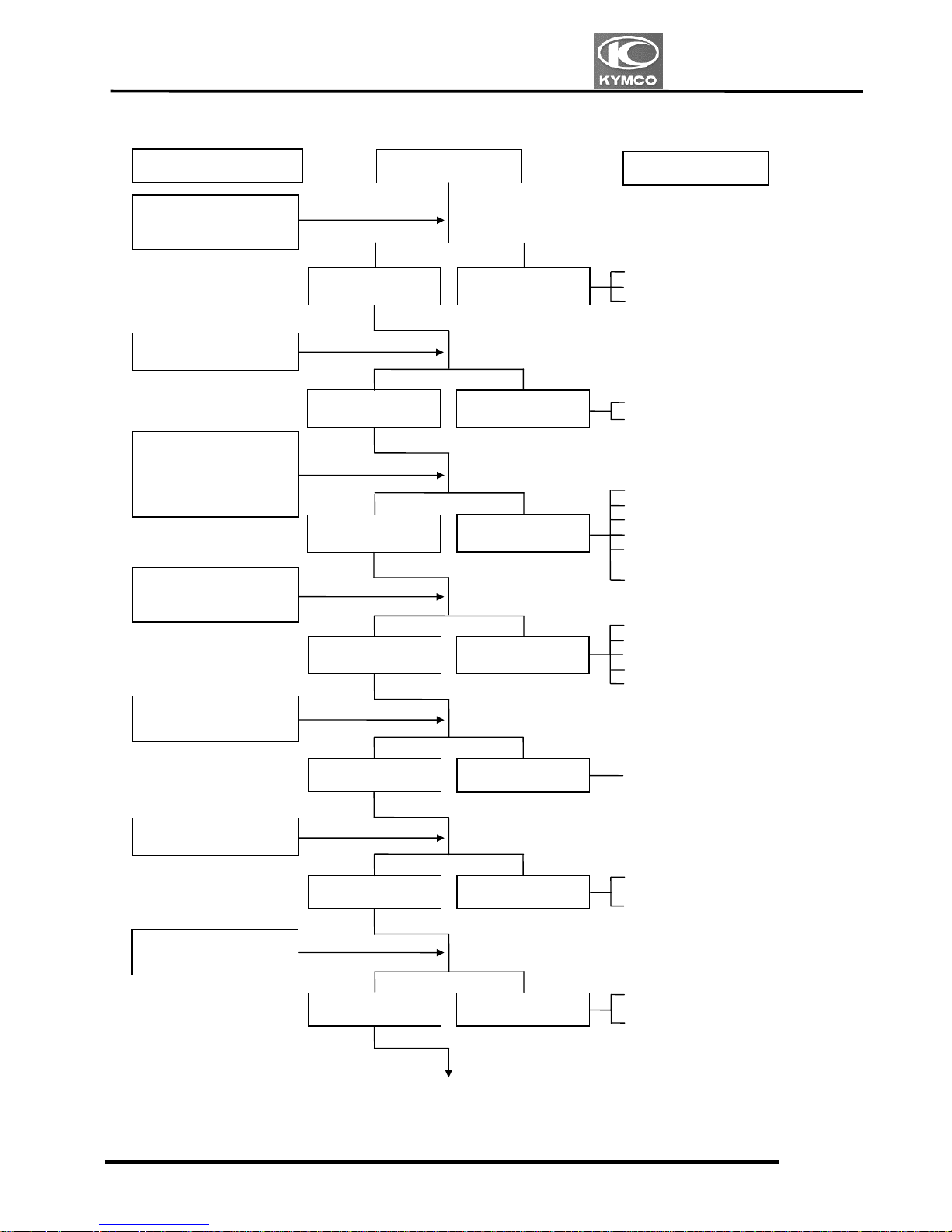
TROUBLESHOOTING
ENGINE WILL NOT START OR IS HARD TO START
Empty fuel tank
Clogged fuel line between fuel
tank and carburetor
Clogged float valve
Clogged fuel filter
Clogged fuel tank cap breather
hole
Clogged fuel valve strainer
Clogged fuel valve passage
Clogged carburetor air balance
tube
Faulty spark plug
Fouled spark plug
Faulty CDI unit
Faulty pulser coil
Faulty exciter coil
Faulty ignition switch
Broken or shorted ignition coil
Faulty or slipping clutch
Valve clearance too small
Valve stuck open
Worn cylinder and piston rings
Leaking cylinder head gasket
Faulty choke control system
Leaking intake manifold
Incorrect ignition timing
Incorrectly adjusted pilot screw
Flooded carburetor
Throttle valve excessively open
Clogged air cleaner
Check if fuel reaches
carburetor by loosening
drain screw
Inspection/Adjustment
Spark jumps
Normal
compression
Engine does not
fire
Weak or no spark
Low or no
compression
Engine fires but
does not start
Remove spark plug and
inspect again
Test cylinder compression
Start engine by
follow-ing normal
startin
g p
rocedure
Fuel reaches
carbureto
r
Fuel does not
reach carbureto
r
Wet spark plug
Dry spark plug
Symptom
Remove spark plug and
install it into spark plug
cap to test spark by
making it contact the
engine
Probable Cause
1. GENERAL INFORMATION
1-22
VENOX250/250i
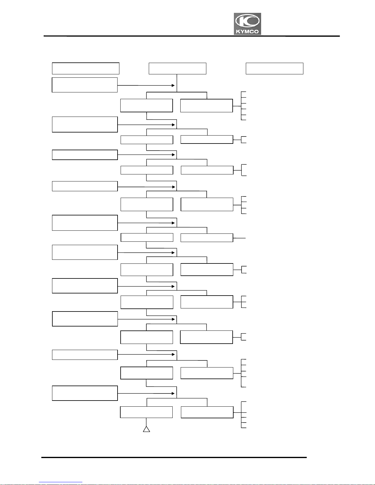
ENGINE STOPS IMMEDIATELY AFTER IT STARTS
Empty fuel tank
Clogged float valve
Clogged fuel filter
Fouled spark plug
Incorrect heat range plug
Fouled spark plug
Faulty CDI unit
Faulty A.C. generator
Faulty ignition coil
Broken or shorted high tension
wire
Faulty ignition switch
Worn cylinder and piston rings
Blown cylinder head gasket
Flaws in cylinder head
Worn valve seat
Seized piston
Clogged carburetor jets
Faulty CDI unit or A.C.
generator
A.C.G. flywheel not aligned
Mixture too rich (turn screw
out)
Mixture too lean (turn screw in)
Symptom
Fuel does not
reach carburetor
Check ignition timing
Check carburetor pilot
screw adjustment
Plug fouled o
r
discolored
Check if fuel reaches
carburetor by loosening
drain screw
Fuel reaches
carburetor
Good spark
Plug not fouled o
r
discolored
Normal
compression
Remove spark plug
Test cylinder
compression (using a
compression gauge)
Check carburetor for
clogging
Correctly adjusted
Incorrectly adjusted
Weak or inter-
mittent spark
Abnormal
compression
Correct timing
Not Clogged
Incorrect timing
Clogged
Remove spark plug and
install it into spark plug
cap to test spark by
making it contact the
engine
Probable Cause
Inspection/Adjustment
1. GENERAL INFORMATION
1-23
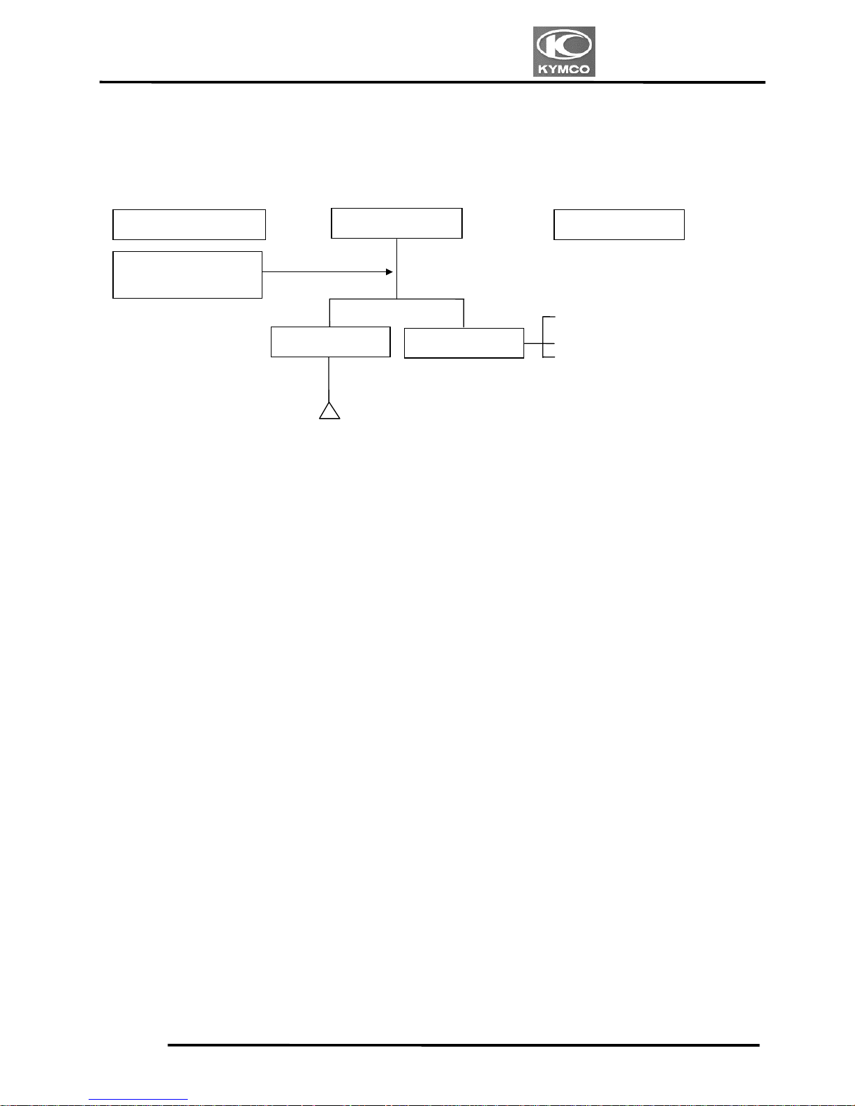
VENOX250/250i
Carburetor not securely
tightened
Faulty intake manifold gasket
Deformed or broken carburetor
O-ring
Inspection/Adjustment
Symptom
No air leak
Air leaks
Check carburetor
insulator rubber for air
leaks.
Probable Cause
1. GENERAL INFORMATION
1-24
VENOX250/250i
POOR PERFORMANCE (ENGINE LACKS POWER)
Clogged air cleaner
Poor fuel flow (Restricted)
Clogged fuel tank cap breather hole
Clogged exhaust muffler
Carburetor fuel level too low
Clogged carburetor high speed fuel
passage
Faulty CDI unit
Faulty A.C. generator
Improper valve clearance
adjustment
Excessively worn valve seat
(protruded valve stem)
Improper valve and seat contact
Worn cylinder and piston rings
Leaking cylinder head gasket
Improper valve timing
Clean and unclog
Fouled spark plug
Incorrect heat range plug
Oil level too high
Oil level too low
Oil not changed
Clogged oil line
Faulty oil pump
Worn cylinder and piston rings
Mixture too lean
Poor quality fuel
Excessive carbon buildup in
combustion chamber
Ignition timing too advanced
Excessive carbon build-up in
combustion chamber
Poor quality fuel
Clutch slipping
Mixture too lean
Ignition timing too advanced
Inspection/Adjustment
Symptom
Engine speed
increases
Correc
t
Engine speed does not
increase sufficientl
y
Incorrec
t
Rapidly accelerate or run
at hi
g
h speed
Start engine and accelerate
lightly for observation
Test cylinder compression
Check carburetor for
clogging
Check ignition timing
(usin
g
a timing light)
Check valve clearance
Correc
t
Incorrec
t
N
ormal
compression
Low compression
Remove spark plug and
ins
pect
Check crankcase for oil
level and condition
Check for engine overheating
Engine overheats
Engine does no
t
overheats
Plug not fouled o
r
discolored
Plug fouled o
r
discolored
Correct and no
t
contaminated
Incorrect o
r
contaminated
Valve train lubricate
d
properly
Valve train not
lubricated properly
Engine knocks
Engine does not knock
Not clogged
Clogged
Check cylinder head for
oil lubrication
Probable Cause
 Loading...