

Page 1
KWANG YANG MOTOR CO.,LTD.
Page 2

Battery & EFI Damage Alert
CELP indication :
If flashing or brightness, it indicates that a fault has
been detected in the vehicle 's EFI or electrical system.
Requires immediate inspection by a KYMCO dealer.
CELP indication
Page 3

Dear KYMCO UXV 500 i Users:
Thank you for purchasing this KYMCO UXV 500i and welcome to the family
of KYMCO UXV500 i riders. To enjoy safety and more pleasant riding, become
thoroughly familiar with this owner manual before you ride the UXV 500i.
You safety depends not only on your own alertness and familiarity with the
UXV 500i but also the UXV mechanical condition.
A pre-ride inspection before every outing and regular maintenance are
essential. The quality of each KYMCO UXV 500 i is guaranteed.
Note: 1. The information and specifications stated in this manual are for
reference only and subject to change without notice.
2.When starting the engine, the battery must be installed to facilitate
starting and increase the engine performance.
Page 4

TABLE OF CONTENTS
AD
Auxiliary Outlet 39 46
Air Clean er 74-76 Daily Saf et y Checks 57
Differential Lock Lever And Indictor
B
Batter y Rem ove 77 Driving Downhill 61
Brake Fluid I nspection 73 Driving Uph il l 62
Back Mirrors 49 Driving Reverse 64
Brake Pedal 50
C
Cargo Bed 52-54 Engine Oil 67-70
Crossing Wat er 63
Cooling System In spect ion 79 Fuel Lever Inspection/ R ef il l ing 30
Changing t he rear gear box oil 71 Fuel Cap key 6
Changing t he front gear box oil 72 Fus e R eplacement 76
Driving Safety 58
E
Emission Control Syst em 65
F
Page 5

TABLE OF CONTENTS
HO
Horn 49 33-38
Hazarb Warn Flashers
Switch
48
Operat ion In st r uction for
Mult i-Meter
P
G
Gear Sel ect or 42 Pillow s Adu ust 41
I
Indicator Lights 31-32
Ignition Sw itch 43 Righ t Glove Compartment Key 6
Ignition Switch Key 6
L
Light Swit ch 44 Start The En gin e 59-60
Location O f Par t s 6-10 Spark Arrest or 66
Periodic Maint enance/ Lubrication 89-91
Parking Brake R elease 51
Packing 61
R
S
Serial N umber Location s 4-5
Spark Plug I nspection 82
Specifications
Seat Rem oval 40
Seat Belt s 40
84-88
Page 6

TABLE OF CONTENTS
T
Throttle Pedal 50
Tool Kit 83
Turn Sign al Ligh t s Sw itc h 47
U
Under-Hood 55-56
W
2WD/4WD Switch 45
Warning Labels Loc at on 11-13
Warning Labels ( English ) 14-21
Warning Labels ( Fr ench) 22-29
Wh eel Removal 80-81
Page 7
This vehicle can be dangerous to operate.
A impact or rollover can occur quickly. even during routine maneuvers such
as turning and driving on hills or over obstacles, if you fail to take proper
precautions.
For your safety, understand and follow all the warnings contained in this
Owner’s Manual and labels on this vehicle.
Keep this Owner’s Manual with this vehicle at all times.
Failure to follow the warnings contained in this manual
can result in serious injury or death.
Particularly important information is distinguished in this manual by the
Following notations:
Indicates a strong possibility that serious injury or death may
WARNING
!
Result if instructions are not followed.
Indicates a possibility that equipment or property damage
CAUTION
!
could result if instructions are not followed.
●Note: Gives helpful information
1
Page 8

This vehicle is not a toy and can be dangerous to operate.
●Always go slowly and be extra careful when operating on unfamiliar terrain.
Always be alert to changing terrain conditions when operating this vehicle.
●Never operate on too rough, slippery, or loose terrain.
●Always follow proper procedures for turning as represent in this manual.
Institution turning at slow speeds before attempting to turn at faster speeds.
Do not turn at intemperate speed.
●Never operate on hills too steep for your abilities and cross the side of a hill,
Practice on smaller hills before attempting larger hills .
●Always use proper procedures if you stall or roll backward when climbing a hill.
To avoid maintain a steady speed when climbing a hill. IN case of you stall or
roll return,follow the procedure for braking described in this manual.
●Operation of this vehicle is restricted to people 16 years of age and older who
possess a valid operator’s license. Usually, no person under the age Of 6
may ride as a passenger on this vehicle.
WARNING
2
Page 9

Safety Watchful
●
Always
procedures described. Pay special attention to the warnings contained
In the manual and on all labels.
read the owner’s manual carefully and follow the operating
Never
●
●
Always
●
Always
operate this vehicle with the canopy frame removed.
wear the seat belt when driving.
follow this age prescription:
WARNING
Operation of this vehicle is restricted to people 16 years of age and older who
possess a valid operator’s license. Usually, no person under the age
Of 6 may ride as a passenger on this vehicle.
3
Page 10
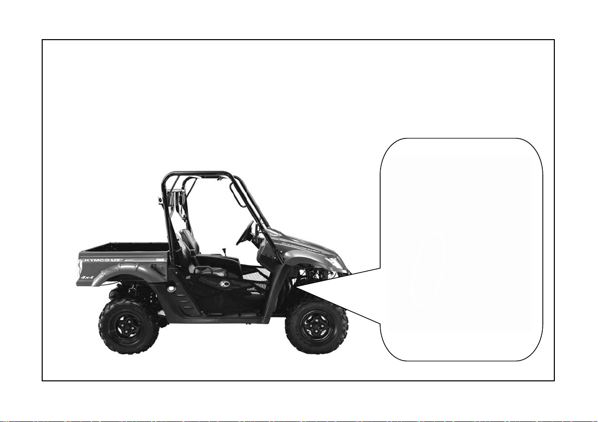
Serial Number Locations
This vehicle has 2 serial numbers:The frame number and Engine serial number.
The frame number is located on the frame near right front wheel place.
Frame Number
4
Page 11
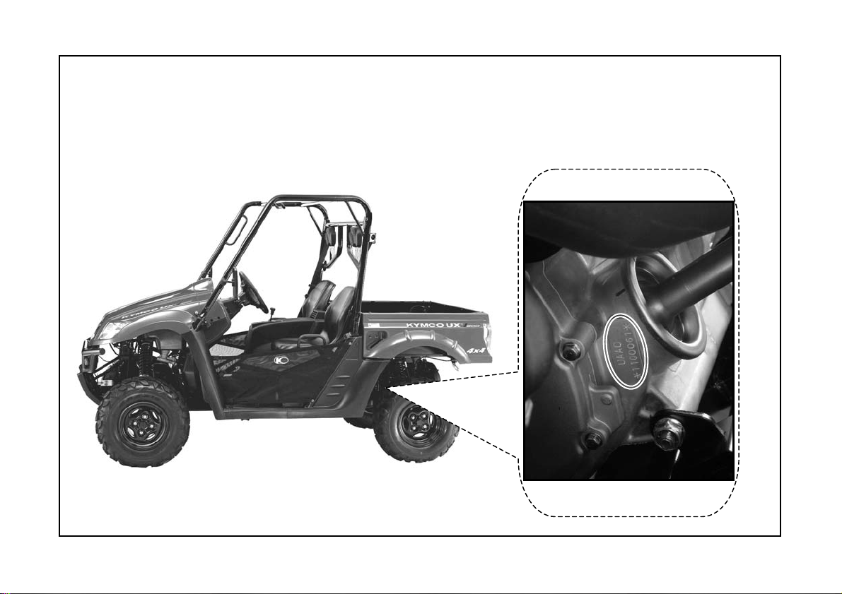
Serial Number Locations
The engine serial number is located on the right side of the engine crankcase.
Engine Serial Number
5
Page 12
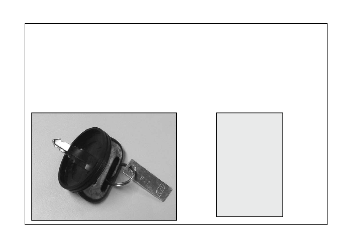
Ignition Switch Key/Fuel Cap Key
Right Glove Compartment Key
Fore keys come with this vehicle. Keep the spare in the safe place.
Fuel Cap Key
Right Glove Compartment
Ignition Switch Key→2PCS
Key →2PCS
6
Page 13
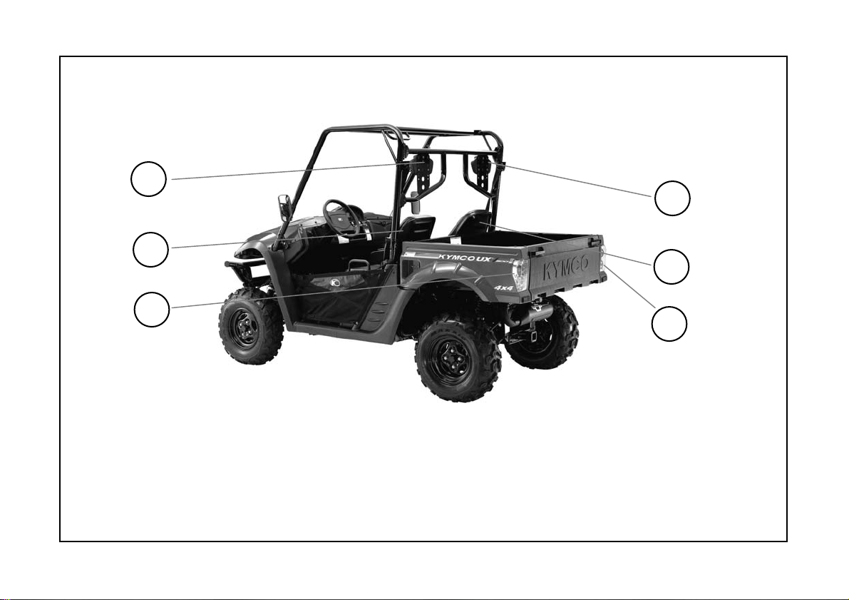
Location Of Parts (1)
4
5
6
1.Right Head Pillow 2.Right Seat 3.Right Tail /Brake/Turn Light
4.Left Head Pillow 5. Left Seat 6.Left Tail /Brake /Turn Light
1
2
3
7
Page 14
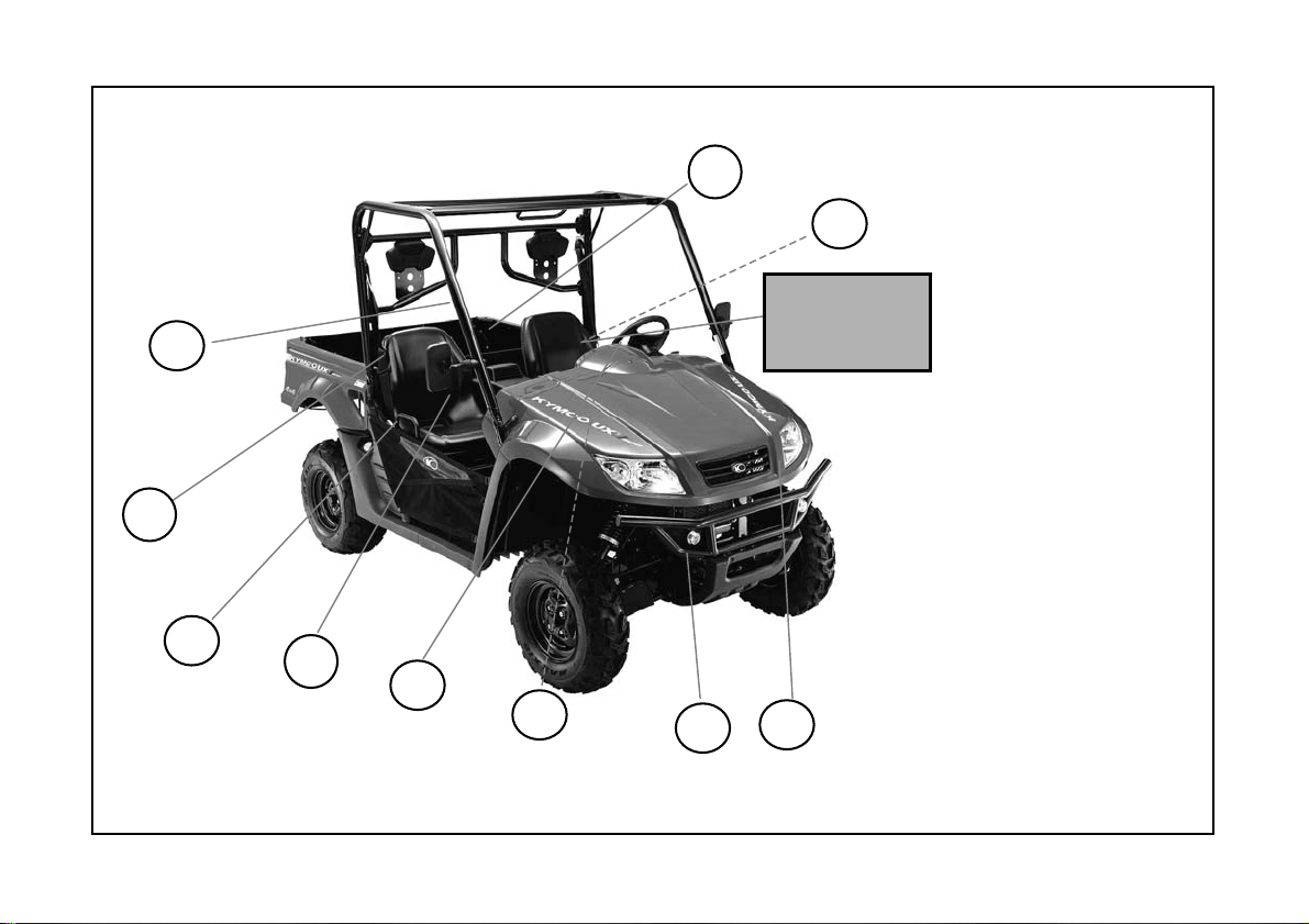
Location Of Parts(2)
8
16
07.Seat Belts
08.Cargo Bed
09.Back mirrors
7
14
15
9
13
12
8
11
10.Headlights
11.Front Turn Lights
12.Battery
13.Steering Wheel
14.Cab Frame
15.hands Bars
16.Tool or Parts Box
(Under the operator’s seat)
10
Page 15
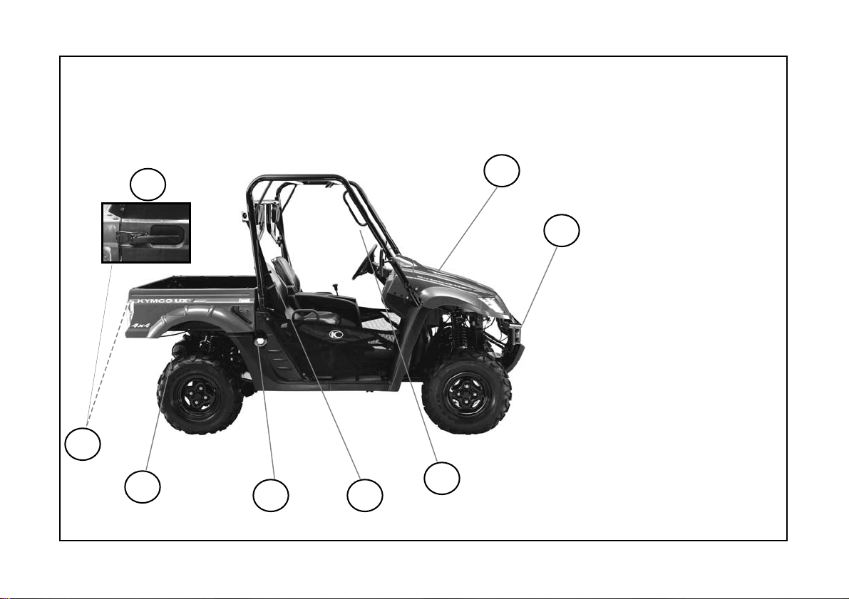
Location Of Parts(3)
23
23
22
21
20
9
19
17
18
17.Under-Hood
18.Bumper
19.Hands Bars
20.Seat Belts
21.Fuel Tank Cap
22.Muffler&
Spark Arrester
23.Latch Handles
Page 16
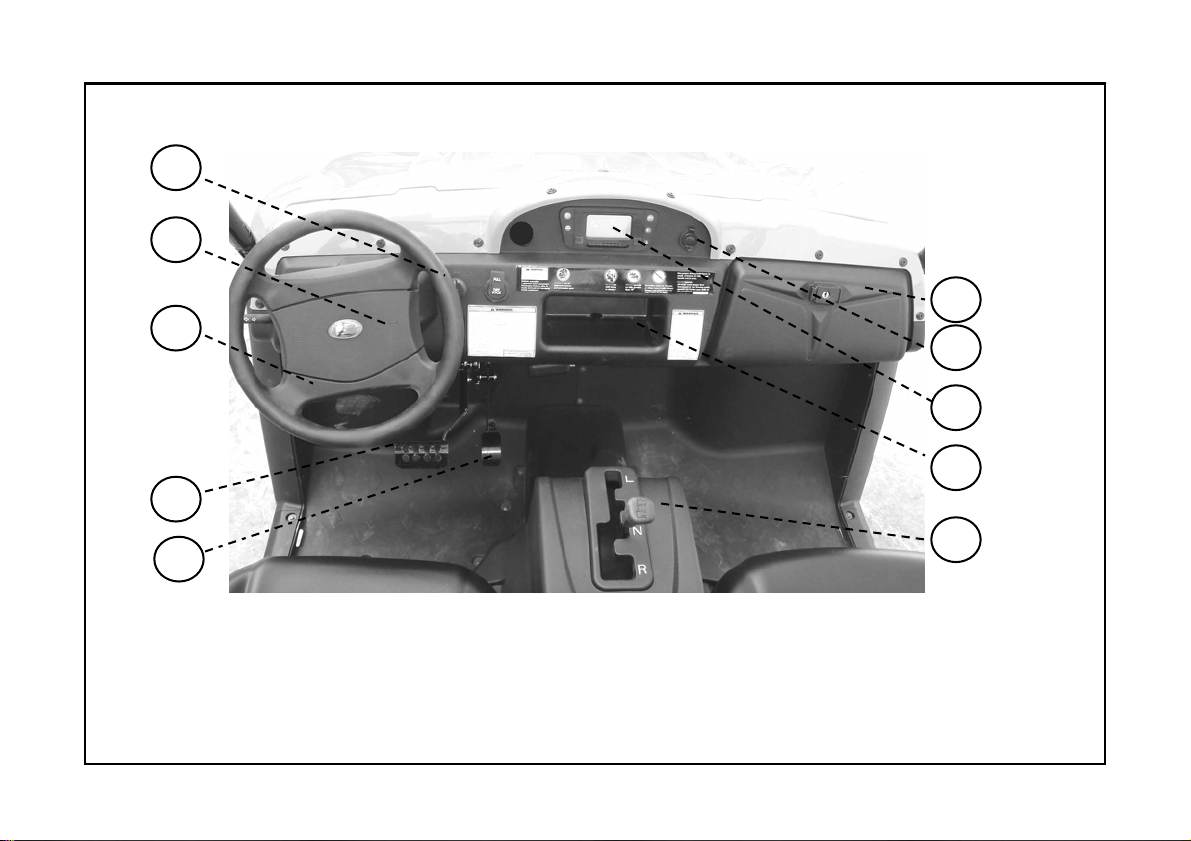
Location Of Parts(4)
29
30
31
32
24
25
26
27
33
24.Right Glove Compartment 25. Auxiliary Outlet 26.Speedometer
27. Center Glove Compartment 28.Shifting The Automatic Transaxle
29. Ignition Switch 30.Hor n31. Steering Wheel 32. Brake Pedal
33.Throttle Pedal
10
28
Page 17
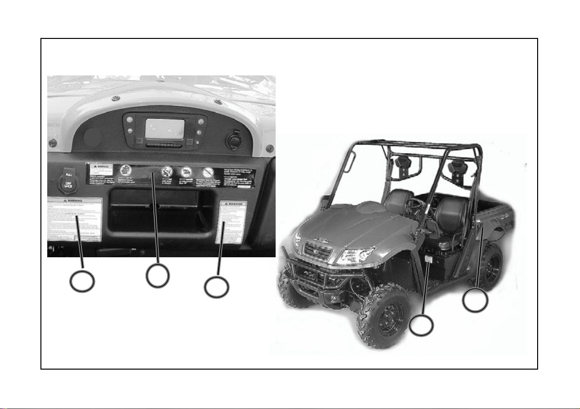
Warning Labels Location
4
3
1
2
5
6
11
Page 18
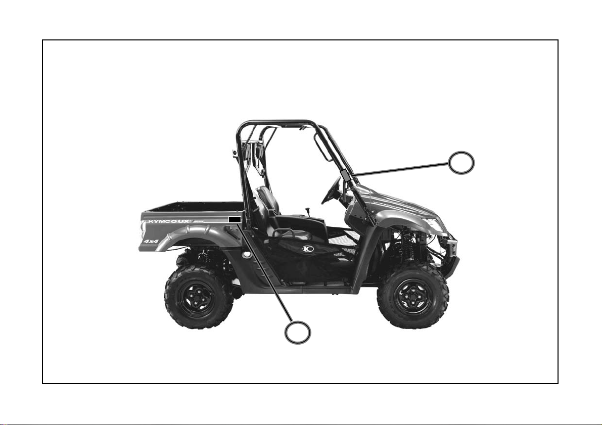
Warning Labels Location
7
8
12
Page 19
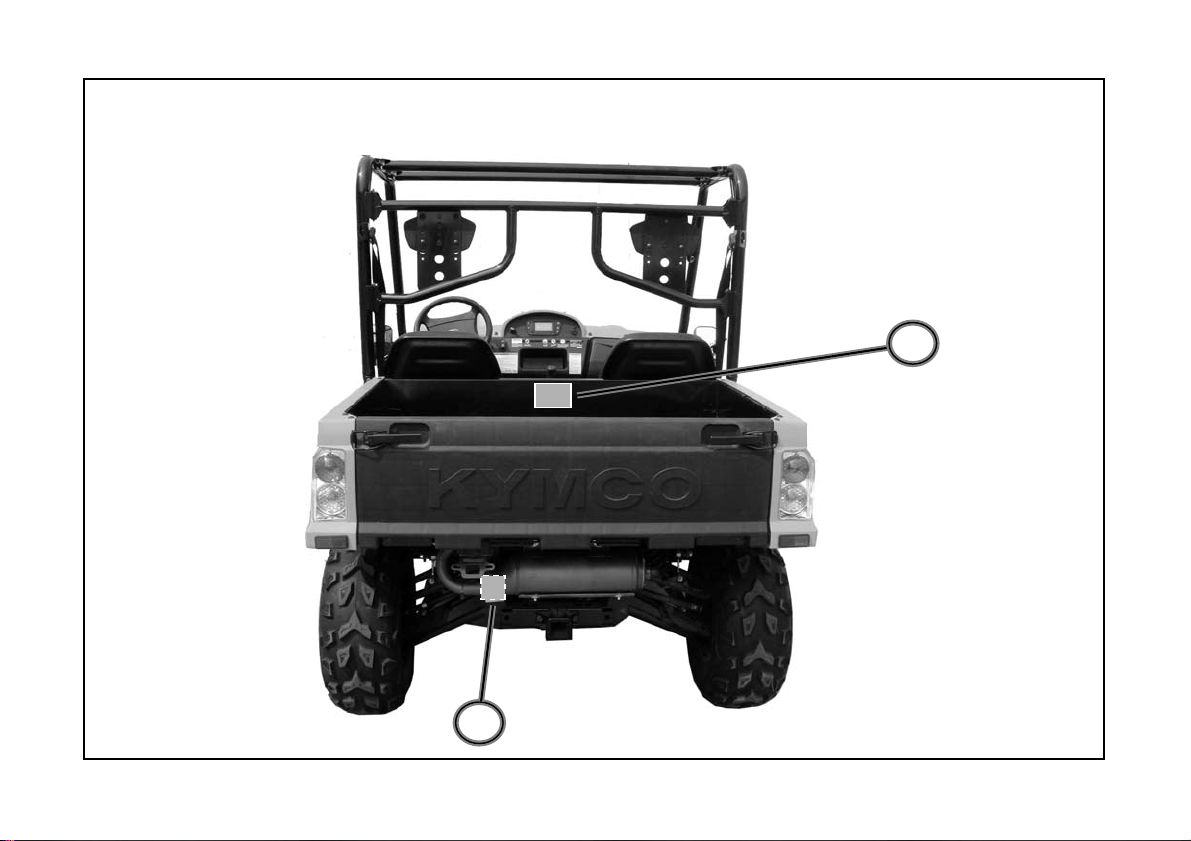
Warning Labels Location
10
9
13
Page 20
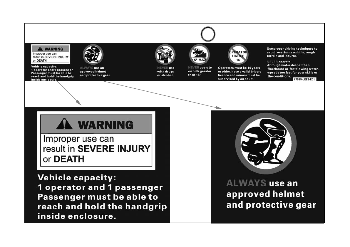
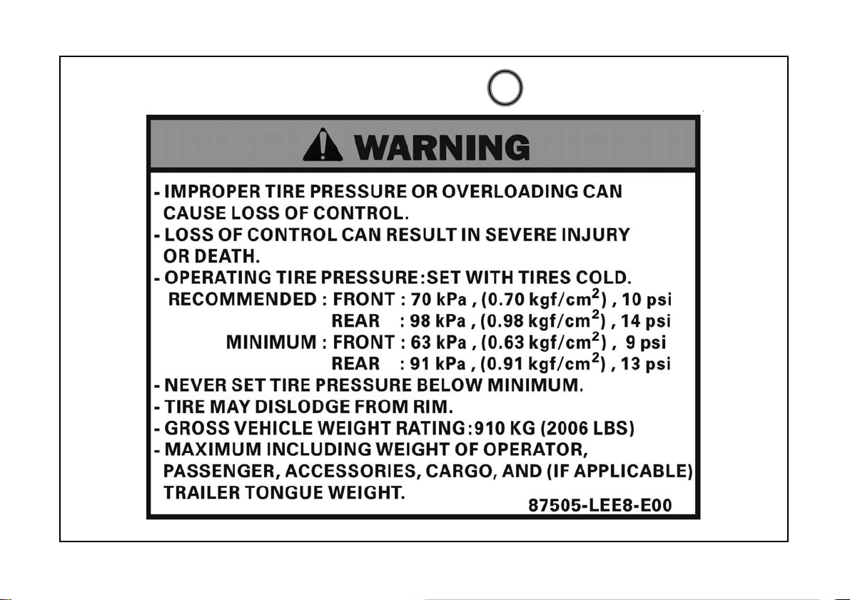
Warning Labels (English)
1
14
Page 21
Warning Labels (English)
1
15
Page 22
Warning Labels (English)
1
16
Page 23

Warning Labels (English)
2
17
Page 24
Warning Labels (English)
3
4 9
5
10
18
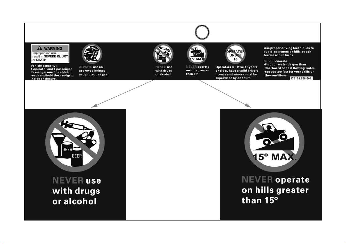
Page 25
Warning Labels (English)
6
19
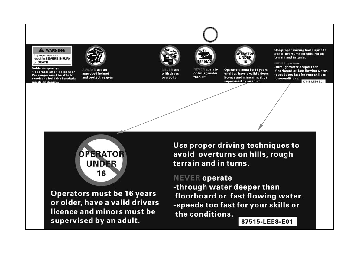
Page 26
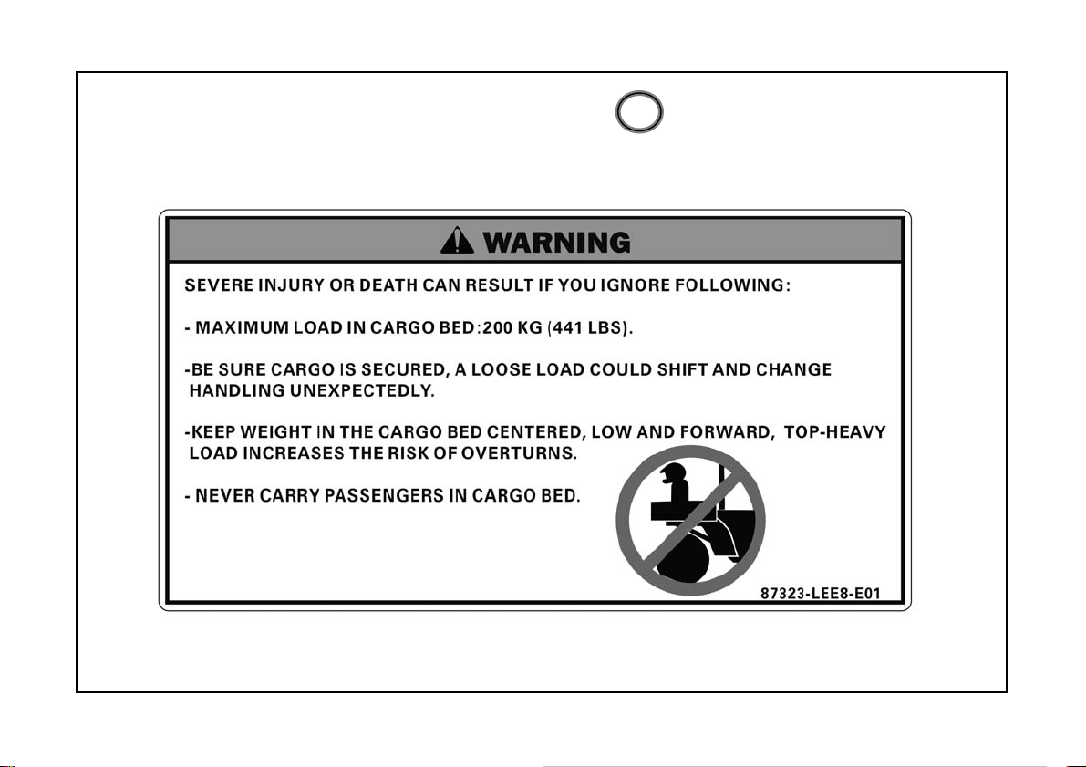
Warning Labels (English)
7
20
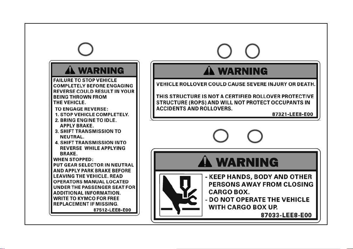
Page 27
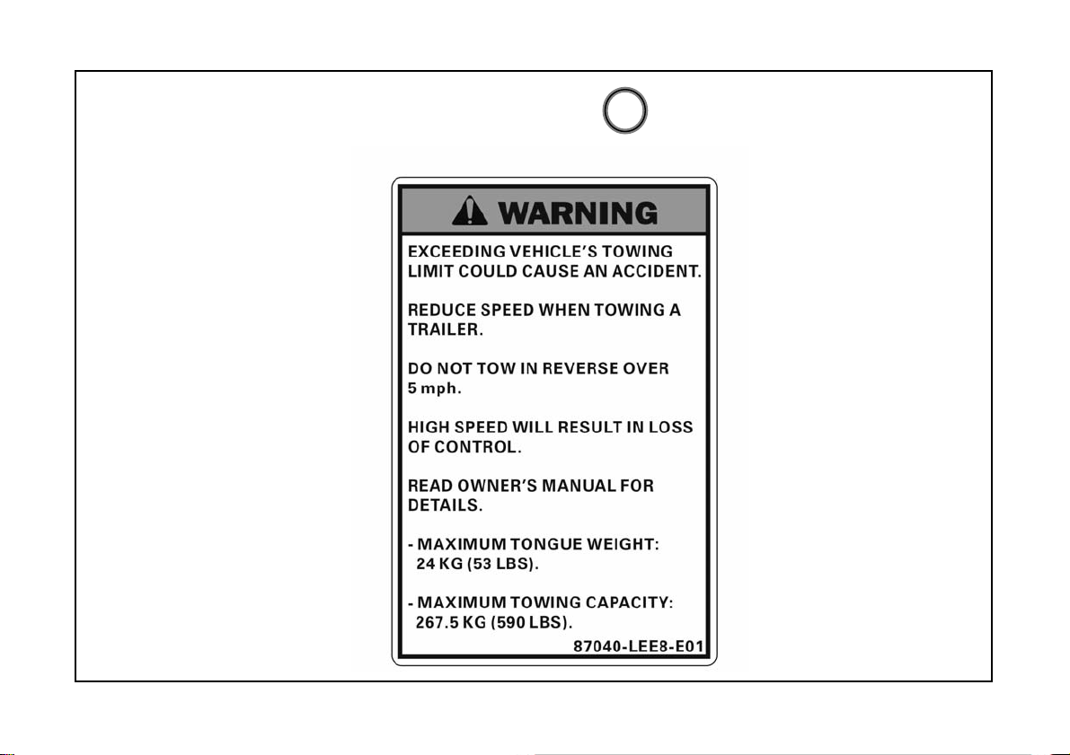
Warning Labels (English)
8
21
Page 28
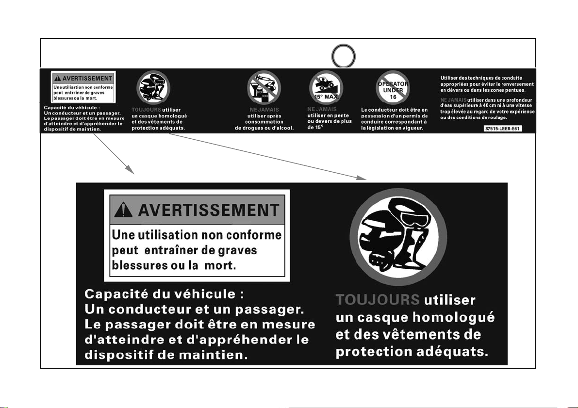
Warning Labels (French)
1
22
Page 29

Warning Labels (French)
1
23
Page 30
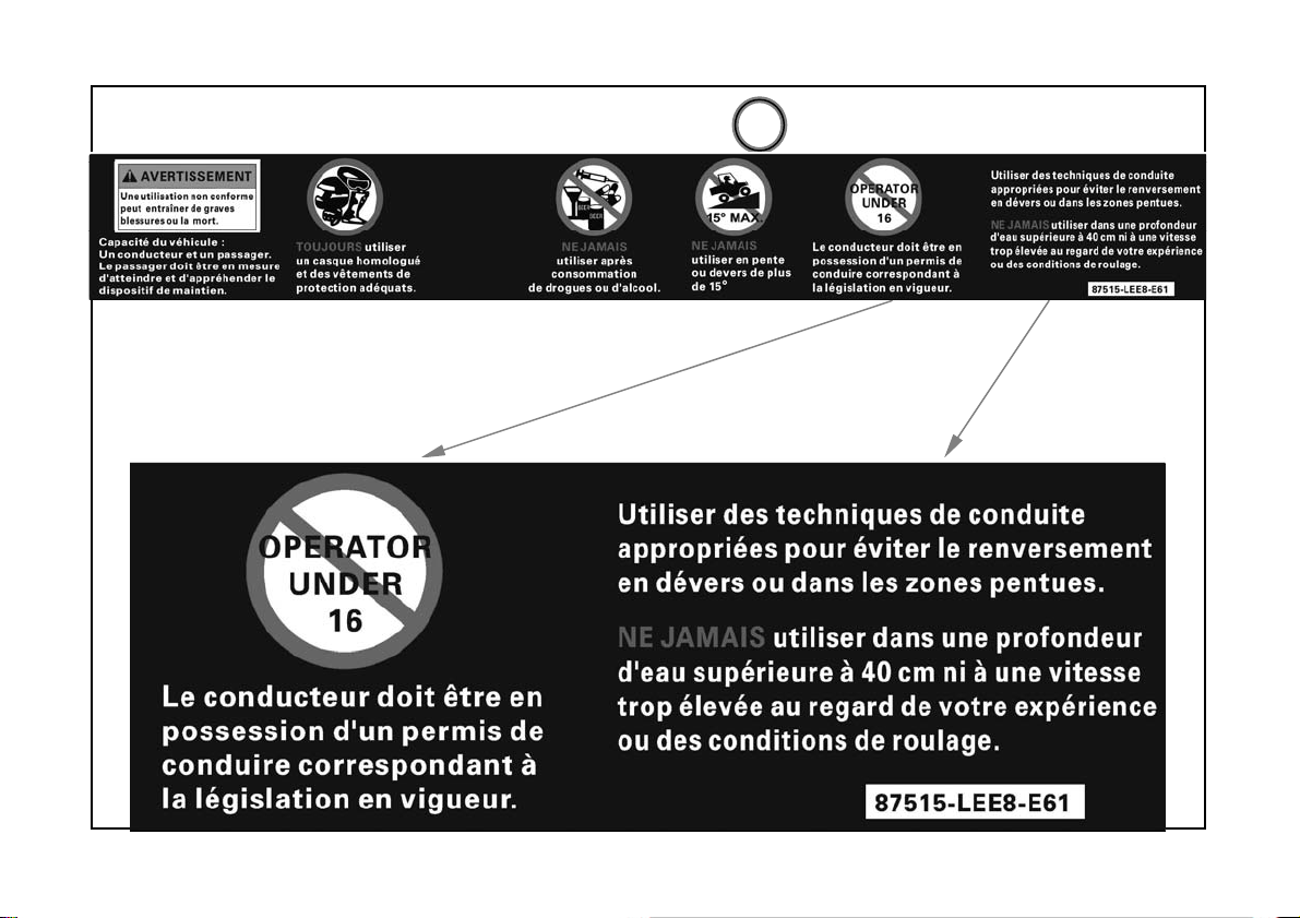
Warning Labels (French)
1
24
Page 31

Warning Labels (French)
2
25
Page 32

Warning Labels (French)
3
4 9
5
10
26
Page 33

Warning Labels (French)
6
27
Page 34

Warning Labels (French)
7
28
Page 35

Warning Labels (French)
8
29
Page 36

Features And Controls
Fuel Lever Inspection/Refilling
Check if fuel is sufficient.
If the fuel gauge pointer is E(flash).refill
nonleaded gasoline as soon as possible.
(Refilling Method)
1.Turn the tank cap counterclockwise with
hand to open the cap.
2.Use only nonleaded gasoline.
3.Turn the fuel tank cap clockwise to tighten
it.
4.Close the fuel tank cap in the reverse
order of opening.
CAUTION
!
OPEN CLOSE
Be sure to stop the engine before refilling.The gasoline level shall not
exceed the reference plate;otherwise the fuel will penetrate out.
30
Page 37

Features And Controls
Indicator Lights
The indicator lights on the console display:
1. Lower Gear 2. High Gear 3.Neutral Gear 4.Reverse Gear 5. Parking Gear
6. Right Turn Signal Indicator Light and Left Turn Signal Indicator Light
7. High Beam Indicator Light 8. FI System Indicator Light 9.Lock:( Differential
Lock Indicator Light )10.Battery Low Voltage Indicator Light 11. High Coolant
Temperature Indicator Light 12. Parking Brake
8
10
6
9
7
1112
5
2134
31
Page 38

Features And Controls
Instruments and Indicators
1.Speedometer 2. Km/h or Mph 3. Clock 4. 4WD 5.Fuel Gauge 6.ODO Meter
7. Adjust Button 8.Engine Tachometer
4
5
8
1
6
2
3
7
32
Page 39

Features And Controls
Operation Instruction for Multi-meter
Button A (MODE)
Button B (SET)
33
Page 40

Features And Controls
Operation Instruction for Multi-meter
Button A (MODE)
Press and hold button A until 2
seconds over.
Shift the unit mph or km/h
34
Page 41

Features And Controls
Operation Instruction for Multi-meter
Press and hold button B until 2
Button A (SET)
Shift function to ODO or TRIP
seconds over.
35
Page 42

Features And Controls
Operation Instruction for Multi-meter
Press and hold button A and B
until 2 seconds over.
Simultaneously to reset to zero
when at TRIP function.
Button A (MODE)
Button B (SET)
36
Page 43

Features And Controls
Operation Instruction for Multi-meter
Press and hold button A and B
until 5 seconds over . when at
ODO function then you can see
clock position is flash word .
Button A (MODE)
Button B (SET)
37
Page 44

Features And Controls
Operation Instruction for Multi-meter
When you seeing clock position is
flash word . You can start setting
hour item. Press button B adjust
correct hours then Press button A
you can see minute
flash. adjust correct minute.
Waiting for 2second .finish times
setting.
position is
Button A (MODE)
Button B (SET)
38
Page 45

Features And Controls
Auxiliary Outlet
The 12-volt receptacle has spade
connections on the back that may be used to
power an auxiliary light or other optional
accessories or lights. The connections are
behind the console,under the hood.
Auxiliary Outlet
39
Page 46

Features And Controls
Seat Removal
•Pull up on front of seat it toward the
front of vehicle.
•Install the seat by sliding the tabs into
the rear of the seat base.
•Push down firmly on the front of the
pins are fully seated into the grommets.
Seat Belts
The UXV500i is equipped with lapshoulder seat belts for the operator
and passenger.
40
operator
passenger
Page 47

Features And Controls
Pillows adjust
If you want to adjusting your pillows.
Remove 3 bolts then adjusting you need pillow position install 3 bolts.
41
Page 48

Features And Controls
Gear Selector
1.Lower Gear
2.High Gear
3.Neutral Gear
4.Reverse Gear
5.Parking Gear
To change gears,stop the vehicle and
with the engine idling, move the lever
to the desired gear.
Do not attempt to shift gears with
engine speed above idle or while the
vehicle is moving.
Always place the transmission in gear
with the parking brake locked
whenever the vehicle is left
unattended.
.
Maintaining shift linkage adjustment is
important to assure proper
transmission function .
See your dealer if you experience any
shifting problems.
42
Page 49

Features And Controls
Switches
Ignition Switch
The ignition switch is a three-position,keyoperated switch, The key can be removed
from the switch when it is in the OFF
position.
ON: Electrical circuits are on
Electrical equipment can be used.
OFF: Engine off .All electrical circuits are
off except Acc.12V
START: Electrical starter is engaged by
holding ignition switch key in this
position. Upon release ,the key will
return to the ON position.
43
Page 50

Features And Controls
Switches
Light Switch
• The ignition switch key must be in the ON
position to operate the headlights.
• The switch has 4 positions.
1:Light off -At this position , light is turn off.
2: Position light - At this position , light is
turn off
3.LO Headlight Beam- When you select
this position . low beam will illuminate.
4.Hi Headlight Beam- When you select this
position .high beam will illuminate .High
beam indicator light will turn on.
1
4
3
2
44
Page 51

Features And Controls
Switches
Drive Select Switch
The 2WD/4WD allows the operator to operate
the vehicle in either two-wheel drive
(rear wheel) or four wheel drive(all wheels)
For normal riding on flat,dry,hard surfaces,
two-wheels drive should be sufficient.
In situations when additional traction is
necessary,for-wheel drive would be the
desired choice.
To either engage or disengage the front
wheels move the switch to the 4WD position
or the 2WD position.
Drive Select Indicator
Displays 4WD when selected by the 4WD
drive selector switch.
45
Page 52

Features And Controls
Differential Lock lever and
indicator
The front axle is equipped with a
lockable differential that allows the
operator to choose between an open
differential or a closed differential in
low traction situations.
Pulling the lock lever up.
To lock the differential on the 4WD,
move the 4WD differential Button.
46
Page 53

Features And Controls
Switches
Turn Signal Lights Switch
When you want direction change just raise
or lower the lever the lever until the green
arrow starts to flash.hold it there until you
complete your direction change .
A green arrow on the instrument panel
will flash in the direction of the turn or
lane change.
When you returned to center position turn
signal lights will not flash.
1.Right turn- raise the lever will flash
arrow .
2.Left turn- --lower the lever will flash
arrow .
47
Page 54

Features And Controls
Switches
Hazard Warn Flashers Switch
Your hazard warn flashers let you warn
others.They also let police know you
have a problem.
Your front and rear turn signal lights will
flash on and off.
Pressing the switch .Turn signal lights
will flash on the meter.
When the hazard warn flashers are ON
your turn signal lights won’t work.
48
Page 55

Features And Controls
Switches
Horn
You can sound born by pressing the
born symbols on your steering wheel
Horn
Back Mirrors
Your back mirrors is convex.A convex
mirror’s surface is curved so you can see
more from the seat.
Back Mirrors
49
Page 56

Features And Controls
Brake Pedal(1)
Depress the brake pedal to slow or stop or
stop the vehicle.
Throttle Pedal(2)
Push the pedal down to increase engine
speed .Spring pressure returns the pedal to
the rest position when released.
Always check that the throttle pedal returns
normally before starting the engine. Make
sure there’s adequate throttle pedal free
play.
(2)
(1)
50
Page 57

Features And Controls
Parking Brake Release(3)
To release the parking brake, pull the
release handle Spring pressure helps return
the lever to the released position .make sure
the parking brake lever is functioning
properly before each operation.
51
(3)
Page 58

Features And Controls
Cargo Bed (Lift and lower the cargo bed)
Push the cargo bed release
lever to right side, then
slowly lift up cargo bed until
it stop.
Lower the cargo bed slowly
to its original position and
be sure the it is locked into
place.
To lift
To lower
Cargo Bed Lever
52
Maximum load in cargo bed:200
kg
Page 59

Features And Controls
Cargo Bed(Open and close the tailgate 1)
To open---(1)
Unlock the latches,and then lower
the tailgate.
(1)
Latch(x2)
Pull
53
Page 60

Features And Controls
Cargo Bed(Open and close the tailgate 2)
Place the tailgate in the
original position ,and then
hook the latches.
To close
54
Page 61

Features And Controls
Under-Hood (To Open)
Unhook the hood latches and then slowly tilt the hood up until it stop.
Latch x2
55
Page 62

Features And Controls
Under-Hood (To Close)
Lower the hood slowly to its original position and then hook the hood latches .
Latch x2
56
Page 63

How to operate
Daily Safety Checks
Check the following items each day before operation.
01.Fuel---------------------Enough fuel in tank,no leaks.
02.Engine Oil-------------Oil lever between lever holes(when engine is cold),no
leaks.
03.Air Cleaner------------Check the restriction gauge.
04.Tires --------------------Air pressure(when cold)and check tires cracks, damage or
abnormal wear.Check for any imbedded stones or other
foreign particles in tread.
05.Front wheel Air pressure :0.7kgf/cm²;10psi
06.Rear wheel Air pressure :0.98kgf/cm²;14psi
07.Headlight & other indicate light ----- Check the operate is normal.
08.Brake/Brake oil lever ----- Check the operate and oil lever is normal.
09.Coolant ------Coolant lever between lever lines(when engine is cold),no leaks.
10.Front final gear case & transmission case ----No oil leaks
11.EFI system ------ Engine check lamp hasn’t bright or flashes.
57
Page 64

How to operate
Driving Safely(Driving procedures)
1.Sit in the driver’s seat and fasten the seat belt.
2.After staring the engine and allowing it to warm up,shift the transmission
into gear.
3.Check your surroundings and determine your path of travel.
4.Release the parking brake.
5.Keeping both hands on the steering wheel, slowly depress the throttle with
your right foot and begin driving.Vehicle speed is controlled by the amount of
throttle opening & transmission shifting is automatic.
6.Drive slowly . Practice maneuvering and using the throttle and brakes on
level surfaces.
58
Page 65

How to operate
Start the Engine
!
Never run the vehicle in a closed area, such as a
garage Exhaust gases contain carbon monoxide,
a colorless, odorless, poisonous gas.
Breathing exhaust gas leads to carbon monoxide
poisoning, asphyxiation, and death.
1.Wear the seat belts(both operator and passenger)
2.Set the parking brake.
3.Put the gear shift lever in the “N(neutral) position.
4.Turn the ignition switch clock wise to the START position; then when the engine
starts, release to the RUN position.
WARNING
59
Page 66

How to operate
Start the Engine
!
Do not run the starting attempt. The starter motor may
overheat causing severe starter motor damage. Allow
15 seconds between starting attempts to allow the
starter motor to cool.
CAUTION
Braking/Stopping
Always allow plenty of room and time to stop smoothly. Sometimes quick stops
are inevitable’ so always be prepared.Whether you’re stopping quickly’ do this:
1.Release the accelerator;then press the foot brake pedal to apply the brake.
2.If the wheels lock,release them for a second;then apply them again .On
surfaces such as ice,mud ,or loose gravel’ pump the brake pedal rapidly.
3.Never ride the brake .Even maintaining minimal pressure on the brake pedal
will cause the brake pads drag on the disc and may overheat the brake fluid.
60
Page 67

How to operate
Parking
Parking involves flowing the previous rules for braking;then :
1.After the vehicle stops,shift into neutral gear.
2.Set the parking brake.
3.Turn off the ignition key.
4.If you have to park on the hill,shift to low range,set the parking brake,and
block the wheel on the downhill side.
Driving Downhill
Always drive straight down the hill and always avoid hills sleeper than 15°.
1.Keep both hands on the wheel.
2.Prior to descending the hill,shift into range and release the accelerator to
allow maximum engine brake.Do not use 4 wheel drive when descending
a hill.Engine braking can cause the front wheels to slide reducing steering
control.
61
Page 68

How to operate
Driving Uphill
whenever travel straight uphill, follow these precautions:
1.Always travel straight uphill.
2.Avoid steep hills(15° maximum)
3.Keep both feet on the floor.
4.Proceed at a steady rate of speed and throttle opening.
NEVER OPERATE UP OR
DOWN HILLS STEEPER
THAN 15°
15° maximum
62
Page 69

How to operate
Crossing Water
UXV500i can only operate in water up to its floorboard.Stay away from fast
moving rivers. This vehicle’s tires can be buoyant.In deep water,the vehicle
may lose traction due to floating.
1.Physically check the depth and current of the water, especially if you can not
see the bottom.Also,check for boulders,logs,or any other hidden obstacles.
2.Keep speed slow while maintaining momentum.
3.Make sure you have a way out on the other side of the water.
4.Once you have cleared the water,briefly apply the brakes to make sure they
work.
63
Page 70

How to operate
Driving in Reverse
Follow these guidelines when operating in reverse:
1.Back slowly.
2.Apply the brakes lightly for stopping.
3.Avoid turning at sharp angles.
4.Always avoid backing downhill.
5.Never open the throttle suddenly while backing.
6. Always inspect left and right fields of vision before backing.
64
Page 71

Emission Control System
Crankcase Emission Control System
This engine is equipped with a closed crankcase system .
Blow-by gases forced back to the combustion chamber by the intake system.
The system does not allow the blow-by gases to enter the atmosphere.
Exhaust Emission Control System
The emissions from the exhaust of this vehicle are controlled by engine
design,including factory-set fuel delivery and ignition.KYMCO Exhaust
Emission Control System including catalytic
change any kymco design.
converter system.please do not
Noise Exhaust Emission Control System
Do not modify the engine ,intake or exhaust components, as doing so may
affect compliance with state and local noise level requirements.
65
Page 72

Emission Control System
Spark Arrester
Your UXV 500i has a spark arrester.
The spark arrester be installed and functional when the vehicle operated on
public lands.
Remove method
remove 3 bolts
66
Clean method
Use the iron brush cleaning
carbon on the spark arrester
Page 73

Maintenance And Lubrication
Engine Oil
Always check and change the oil at the OWNER MANUAL standard intervals.
The oil tank is located under the seat.
1.Position the vehicle on the surface.
2.Start the engine and let it idle for 20~30seconds.
3.Stop the engine and remove the seat.
4.Add fresh oil into the oil tank .
Make sure the engine oil at the specified level.
Add oil as necessary. Check for leaks.
Oil quantity:
Engine oil:
Periodic oil change:
3 L (2.64 Imp qt, 3.18 US qt)
Total amount:
3.6 L (3.17 Imp qt, 3.82 US qt)
Recom me n d ed engine oil classification : API
Service SJ typ e or higher
67
0
1 0
SAE 5W
0
-1 0
30
0
50
0
SAE 10W 30
SAE 10W 40
0
0
10
0
0
70
90
-
-
SAE 20W 40
SAE 20W 50
20
-
-
0
30
0
0
0
110 F
0
40 C
Page 74

Maintenance And Lubrication
Engine Oil
1.Engine oil level measurement
A. Place the machine on a level place.
B. Warm up the engine for several minutes and stop it.
C. Check the oil level through the inspection window.
D. The oil level should be between the maximum (H) and minimum (L) marks.
If the level is low, add oil to raise it to the proper level.
NOTE:
Wait a few minutes until the oil level settles
before checking.
H
L
68
Page 75

Maintenance And Lubrication
Engine oil replacement and oil filter cleaning
1. Place the machine on a level place.
2. Warm up the engine for several minutes and stop it.
3. Place a container under the engine.
4. Remove the oil fill cap (1) and oil drain bolt (2)
to drain the oil.
CAUTION:
Be sure no foreign materi al enters the
crankcase.
CAUTION:
When removing the oil filter cap, the
compression spring, oil strainer and O-ring
will fall out. Take care not to lose these
parts.
(1) oil fill cap
(2) oil drain bolt
69
Page 76

Maintenance And Lubrication
NOTE:
Skip steps E to I if the oil filter cartridge is not
being replaced.
Remove the oil filter cartridge with an oil cartridge wrench.
oil filter cartridge
remove lock
70
Page 77

Maintenance And Lubrication
Changing the rear gear box oil
1. Place the vehicle on the a level surface.
2. Place a container under the rear gear box
to collect the used oil.
3.Remove the rear gear box oil drain bolt(1)
and rear gear box oil filler cap (2).
4.Install the rear gear box oil drain bolt(1) and
then tighten it to the specified torque.
5.Fill the rear gear box oil with recommended oil.
6.Install the rear gear box oil filler cap(2) and then
tighten it to the specified torque.
Tightening torque
Drain bolt : 20 N-m (2 kgf-m)
Oil filler cap : 14.7 N-m (1.5 kgf-m)
Recommended oil : SAE 80
Oil quantity :
Periodic oil change
0.25ML
(2)
(1)
71
Page 78

Maintenance And Lubrication
Changing the front gear box oil
1. Place the vehicle on the a level surface.
2. Place a container under the front gear box
to collect the used oil.
3.Remove the front gear box oil drain bolt(1)
and front gear box oil filler bolt (2).
4.Install the front gear box oil drain bolt(1) and
then tighten it to the specified torque.
5.Fill the front gear box oil with recommended oil.
6.Install the front gear box oil filler bolt(2) and then
tighten it to the specified torque.
Tightening torque
Drain bolt : 32 N-m (3.2 kgf-m)
Oil filler bolt : 35 N-m (3.5 kgf-m)
Recommended oil : SAE 80
Oil quantity :
Periodic oil change
0.27ML
72
(2)
(1)
Page 79

Maintenance And Lubrication
BRA KE FLUID IN SPEC TION
Check if the fluid level is below the lower level
mark through the inspection window.
W ARNING
POTENTIAL HAZARD
Brake fluid contacting the skink or eyes.
WH AT CAN HAPPEN
May cause irritation.
HOW TO AVOID THE HAZARD
Avoid contacting brake fluid with the skin
or eyes. In case of contact, flush thoroughly
with water and call a doctor if your eyes
were exposed.
(1) Lower level mark
(2) Upper level mark
73
Page 80

Maintenance And Lubrication
Air Cleaner
Remove the center cover screws.
Remove gear selector bolt and center cover.
74
Page 81

Maintenance And Lubrication
Air Cleaner
Remove air cleaner cover screws and air filter element fixed bolt .
Remove air filter element.
75
Page 82

Maintenance And Lubrication
Air Cleaner
Using high pressure air to clean air filter element .
Inspect the air filter element and replace it if damaged.
76
Page 83

Maintenance And Lubrication
Battery Remove
1. Make sure the ignition switch is OFF.
2. Remove the under-hood hook& pu bolts.
3. Remove the battery cover screws.
4. Disconnect the negative (
(1) from the battery first, then disconnect
the positive (+) terminal lead (2).
5. Remove the battery.
Battery installation
1. Install in the reverse order of removal.
2. After installing the battery, check to see if
the battery cables are routed correctly.
NOTE:
First connect the positive (+) cable and then
negati ve (-) cable to avoid short circu it.
-
) terminal lead
77
(2)
(1)
Page 84

Maintenance And Lubrication
Fuse Replacement
The fuse box stored in the battery
compartment.
To replace a fuse:
1. Make sure the ignition switch is OFF.
2. Remove the under-hood hook& pu bolts.
3. Open the fuse box cap.
4. Pull the old fuse out of the fuse holder.
5. Push the new fuse in to the fuse holder.
6. Close the fuse box cap and install seat.
CAUTION:
To prevent accidental short-circuiting, turn
off the main switch when checking or
replacing a fuse.
(1) (2) (3) (4) (5) (6)
(6)FAN MOTER---------15A
(5)IGNITION--------------15A
(4)LIGHT------------------15A
(3)DC12VPOWER------15A
(2)SPARE-----------------15A
(1)SPARE-----------------30A
78
Page 85

Maintenance And Lubrication
Cooling System Inspection
1. Remove the under-hood hook& pu bolts.
2. Check the coolant level in the c o olant
reservoir when the engine is cold as the
coolant level will vary with engine
temperature.
The coolant level should be between the
maximum and minimum marks.
3. If the level is low, remove the coolant
reservoir cap, and then add coolant or
distilled water to raise it to the specified
level.
Recommended Coolant Solution
Coolant Mixture Ratio:
Water 50%:Antifreeze 50%(1:1)
NOTE:
A permanent type of antifreeze is installed in the
cooling system when shipped.It is colored green
and contains ethylene glycol.It is mixed.It is mixed
at 50% with water and has a freezing point of
-35 °C(-31 °F)
FULL
LOW
79
Page 86

Maintenance And Lubrication
Wheel Removal
1.Elevate the wheel by placing a suitable
stand under the frame.
2.Remove the nuts from the wheel.
3.Remove the wheel assembly.
Wheel Installation
When reinstalling a wheel, tighten the wheel nuts in
a crisscross(rather than a circular)pattern.
Be sure the tapered a side of the wheel nuts(1)face
the wheel rim(2).
Wheel nut torque:
Front:61 N-m(6.1 kgf-m,44 lbf-ft)
Rear:61 N-m(6.1 kgf-m,44 lbf-ft)
Be sure the tapered side of the wheel nuts(1) face
the wheel rim(2).
OK
80
(1)(2)
Page 87

Maintenance And Lubrication
NOTE:
The arrow mark on the tire must point
toward the rotating direction of the wheel.
(1)
(1) A rrow mark
POTENTIAL HAZARD
In stalling wheels improperly.
WHAT CAN HAPPEN
A wheel may come loose, possibly leading
to an accident.
HOW TO AVOID THE HAZARD
Carefully follow the instructions in this
Owner's Manual when installing.
W ARNING
81
Page 88

Maintenance And Lubrication
Spark Plug Inspection
The spark plug is an important engine
component and is easy to inspect.
The condition of the spark plug can indicate the
condition of the engine.
For example, a very white cent er electrode
porcelain color could indicate an intake air leak
or carburet problem for that cylinder.
Do not attempt to diagnose such problem s
yourself.
Instead, take the machine to a KYMCO dealer.
You should periodically remove and inspect t h e
spark plug because heat and deposits will cause
the spark plug to slowly break down and erode.
If electrode erosion becomes excessive, you
should replace the spark plug with one of th e
proper type.
Standard spark plug (NGK): CR7E
Before installing the spark plug, measure the
electrode gap with a feeler gauge and adjust to
specification.
Spark plug gap:
0.6~0.7 mm (0.024~0.028 in)
(A) Spark plug gap
(A)
82
Page 89

Maintenance And Lubrication
Tool Kit
The tool kit put down location at
The tool kit includes the following items:
(1) Hexagon wrench
(2) Spark plug wrench
(3) 8/12;10/14;17/19 mm wrench
(4) Screwdriver
(5) Screwdriver handle
(6) Tool bag
(7)Air pressure gauge
Right Glove Compartment .
(6)
(7)
(4)
(1) (2)(3) (5)
83
Page 90

Specifications
MODEL UXV500 i(ON ROAD)
DIMENSIONS:
OVERALL LENG TH
OVERALL WIDT H
OVERALL HEIGH T
SEAT HEI G HT
WHEELBASE
GROU ND CLEARANCE
MINMUN. TURNI NG RADIUS
BA SIC WEI GHT:
WITH OIL AND FULL FU EL TANK
MAX. CARGO BED LO AD
DR Y WEIGHT
MAX. W EIGH T CAPACI TY
ENGINE:
ENGI NE TYPE
CYLINDER ARRAN GEMEN T
BOREx STROKE
ACTUAL DISPLACEMEN T
COM PRESSI ON R ATIO
ST ARI NG SYSTEM
LU BRI CATION SYSTEM
2870mm
1500mm
1850mm
805mm
1910mm
310mm
4060mm
560kg
200kg
525kg
350kg
4 -STROKE,DOHC
SI NGLE CY LINDER
92X75mm
498.5cc
10.5:1
ELECT RI C STARTER
WET SUMP
84
Page 91

Specifications
MODEL UXV500 i(ON ROAD)
ENGINE GEAR BOX:
CAPICITY/EXCHANGE/TYPE
FRONT GEA R BO X:
CAPICITY/EXCHANGE/TYPE
REAR GEAR BOX
CAPICITY/EXCHANGE/TYPE
AIR FILTER:
FUEL:
TY PE
FU EL TANK CAPACIT Y
THROTTLE BODY:
TY PE/MANUFACTURER
SPA RK PL UG :
TY PE/MANUFACTURER
SPARK PL U G
CLUTH TYPE:
3.6L/3.0L/5W-30
270ML/270ML/SAE80#
250ML/250ML/SAE80#
SPONGE ELEM EN T
UNLEADED GASO LINE
32L
PT A1/KYMCO
CR7E-NGK
0.6~0.7mm
WET CENTRIFUGAL AUTOMATIC
85
Page 92

Specifications
MODEL UXV500 i(ON ROAD)
TRANSMISSION:
PRIMARY REDUCTION SYSTEM
SECONDARY RE DUCTION S YSTEM
T RANSMISSION TYPE:
TIRE:
TY PE
SIZE(FRONT)
SIZE(REAR)
WHEEL MATERI AL
PR ESSURE FR/R R
BRAKES:
SYST EM FR ONT AND R E AR UN IFI E D
T YPE(FRO NT) DU AL DISC BRAKE
T YPE(REAR) SI NGLE DISC BRAKE
OPER ATION FOOT O PERATION
SUSPENSION:
FR ONT SUSPENSION DOUBLE WISHBO NE
RE AR SUSPENSI ON DOUBLE WISHBO NE
SHOCK ABSORBER : COIL SPR ING/OIL DAMPER
V-BELT
SH AFT DR IVE
V-BEL T AUTOM ATIC
TUBELESS
25x 8-12
25x10-12
STEEL
0.7/ 0. 98(kgf/cm2) O R 10/ 14 psi
86
Page 93

Specifications
MODEL UXV500
WHEEL TRAVEL:
FRONT WHEEL TRAVEL
RE AR WHEEL TRAVEL
ELETRICAL:
IGN ITION SY STEM
GENERATOR SY STEM
BATTERY TYPE
BAT TER Y CAPACI TY
HAEDLI G HT TYPE:
BULB VO LT AGE
WA TTA GE X QUANTI TY:
HAEDLIGHT: 12V35/35W*2
NO .PLATE LIGHT 12V5W
REAR LIGH T 12V21/5W*2
INDICATORS FR/RR DIRECT ION 12V1 0 W
BRAKE LI G HT 12V21/5W*2
POSITION LIGHT 12V21/5W*2
190mm
190mm
DC, E CU AUTOM A TIC CON TR O L
A.C.MAGNETO
MF-VTX20L
12V18AH
HS1
(
ON ROAD)
i
87
Page 94

Specifications
MODEL UXV500 i(ON ROAD)
SPECI FIED FUSES:
MAIN FUSE 30A
FAN M O TER
IGNITION
LIGHT
DC12VPOWER
SPARE
SPARE
15A
15A
15A
15A
15A
30A
888990
Page 95

Page 96

Page 97

91
Page 98

Maintenance Record
Page 99

Maintenance Record
Page 100

Maintenance Record
 Loading...