

Page 1
KWANG YANG MOTOR CO.,LTD.
Page 2

Page 3

Dear KYMCO UXV 500 Users:
Thank you for purchasing this KYMCO UXV 500 and welcome to the family
of KYMCO UXV500 riders. To enjoy safety and more pleasant riding, become
thoroughly familiar with this owner manual before you ride the UXV 500.
You safety depends not only on your own alertness and familiarity with the
UXV 500 but also the UXV mechanical condition.
A pre-ride inspection before every outing and regular maintenance are
essential. The quality of each KYMCO UXV 500 is guaranteed.
Note: 1. The information and specifications stated in this manual are for
reference only and subject to change without notice.
2.When starting the engine, the battery must be installed to facilitate
starting and increase the engine performance.
Page 4

INDEX
AD
Auxiliary Outlet 32 39
Air Cleaner 62 Daily Safet y Checks 47
B
Batter y r emove 65 Driving Downhill 51
Brake Fluid Inspection 61 Driving Uphill 52
Brake Pedal 40 Driving Reverse 54
Differential Lock Lever And Indictor
Driving Safety 48
CE
Cargo Bed 42-44 Emission Contr ol System 55-56
Choke Knob 32 Engine Oil 57-59
Crossing Water 53
Cooling System Inspection 67 Fuel Lever I nspection/Refilling 23
F
Fuse Replacement 66
Fuel Cap Key 6
Page 5

r
INDEX
GO
Gear Selector 35 26-31
Operation Instruction for Multi-Mete
P
I
Indicator Lights 24-25 Pillows Aduust 34
Ignition Switch 36 Parking Brake Release 41
Ignition Switch Key 6 Packing 51
PERIODIC MAINTENANCE/L UBRICATI O N
77-79
LR
Light Sw it ch 37 Right Glove Compartment Key 6
Location Of Part s 7-10
S
Serial Number Locat ions 4-5
Start The Engine 49- 50
Spark Arrestor 56
Spark Plug I nspection 70
Specifications
72-76
Page 6

INDEX
T
Throttle Pedal 40
Tool Kit 71
U
Under-Hood 45-46
W
2WD/4WD Swit ch 38
Warning Labels Locat on 11-13
Warning Labels 14-22
Page 7
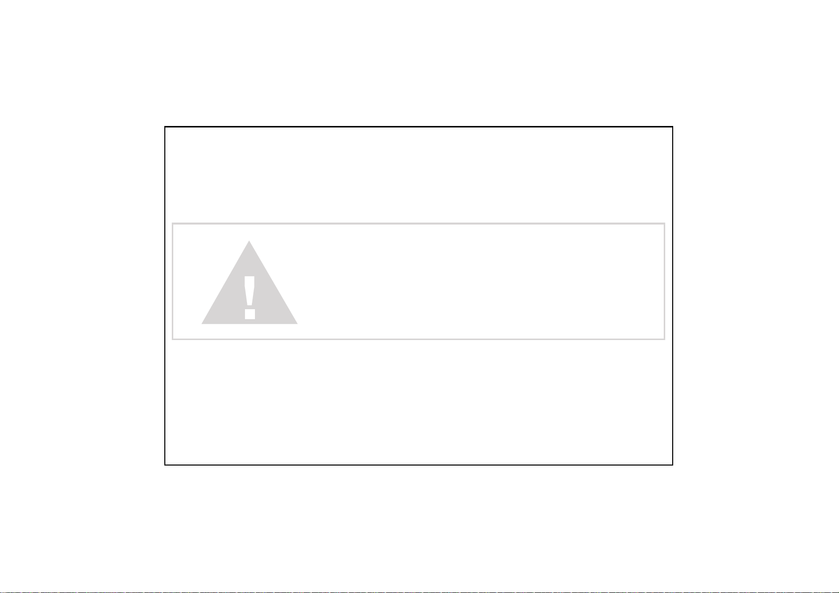
This vehicle can be dangerous to operate.
A impact or rollover can occur quickly. even during routine maneuvers such
as turning and driving on hills or over obstacles, if you fail to take proper
precautions.
For your safety, understand and follow all the warnings contained in this
Owner’s Manual and labels on this vehicle.
Keep this Owner’s Manual with this vehicle at all times.
Failure to follow the warnings contained in this manual
can result in serious injury or death.
Particularly important information is distinguished in this manual by the
Following notations:
Indicates a strong possibility that serious injury or death may
WARNING
!
Result if instructions are not followed.
Indicates a possibility that equipment or property damage
CAUTION
!
could result if instructions are not followed.
●Note: Gives helpful information
1
Page 8
This vehicle is not a toy and can be dangerous to operate.
●Always go slowly and be extra careful when operating on unfamiliar terrain.
Always be alert to changing terrain conditions when operating this vehicle.
●Never operate on too rough, slippery, or loose terrain.
●Always follow proper procedures for turning as represent in this manual.
Institution turning at slow speeds before attempting to turn at faster speeds.
Do not turn at intemperate speed.
●Never operate on hills too steep for your abilities and cross the side of a hill,
Practice on smaller hills before attempting larger hills .
●Always use proper procedures if you stall or roll backward when climbing a hill.
To avoid maintain a steady speed when climbing a hill. IN case of you stall or
roll return,follow the procedure for braking described in this manual.
●Operation of this vehicle is restricted to people 16 years of age and older who
possess a valid operator’s license. Usually, no person under the age Of 6
may ride as a passenger on this vehicle.
WARNING
2
Page 9

Safety Watchful
●Always read the owner’s manual carefully and follow the operating
procedures described. Pay special attention to the warnings contained
In the manual and on all labels.
●
Never operate this vehicle with the canopy frame removed.
Always wear the seat belt when driving.
●
Never operate this vehicle on a public road. even a dirt or gravel one
●
WARNING
,because you may not be able to avoid colliding with other vehicles .
Always avoid paved surfaces. This vehicle isn’t designed to be used on
●
paved surfaces and may seriously affect handling and control.
Always follow this age prescription:
●
Operation of this vehicle is restricted to people 16 years of age and older who
possess a valid operator’s license. Usually, no person under the age
Of 6 may ride as a passenger on this vehicle.
3
Page 10

Serial Number Locations
This vehicle has 2 serial numbers:The frame number and Engine serial number.
The frame number is located on the frame near right front wheel place.
Frame Number
4
Page 11
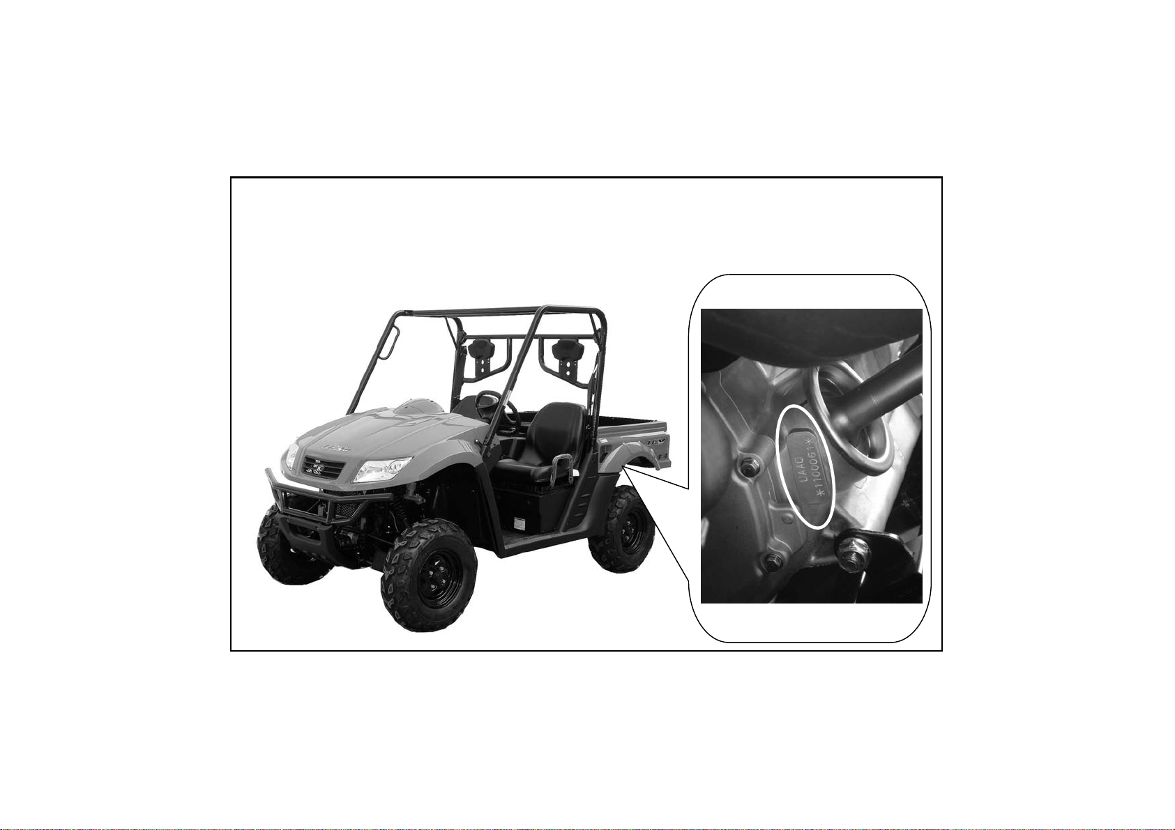
Serial Number Locations
The engine serial number is located on the right side of the engine crankcase.
Engine Serial Number
5
Page 12
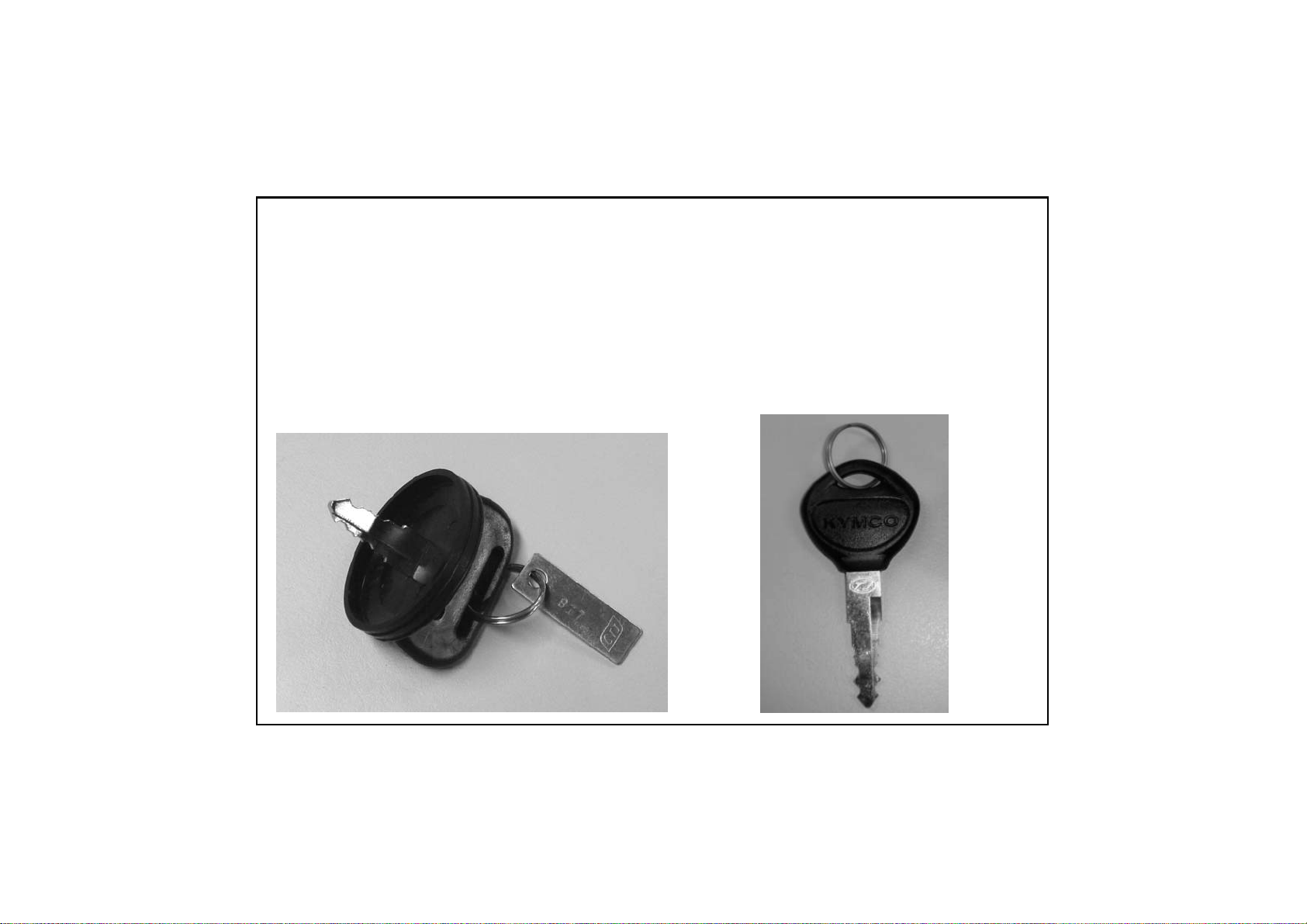
Ignition Switch Key/Fuel Cap Key
Right Glove Compartment Key
Fore keys come with this vehicle. Keep the spare in the safe place.
Fuel Cap Key
Right Glove Compartment
Ignition Switch Key→2PCS
Key →2PCS
6
Page 13
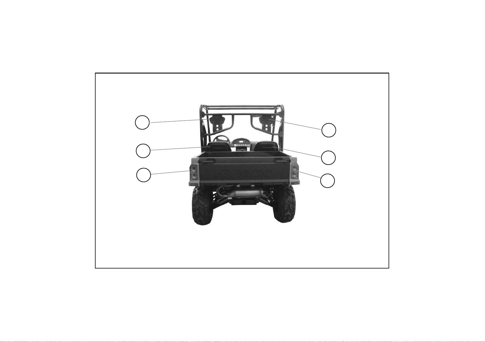
Location Of Parts (1)
4
5
6
1.Right Head Pillow 2.Right Seat 3.Right Tail /Brake Light
4.Left Head Pillow 5. Left Seat 6.Left Tail /Brake Light
1
2
3
7
Page 14
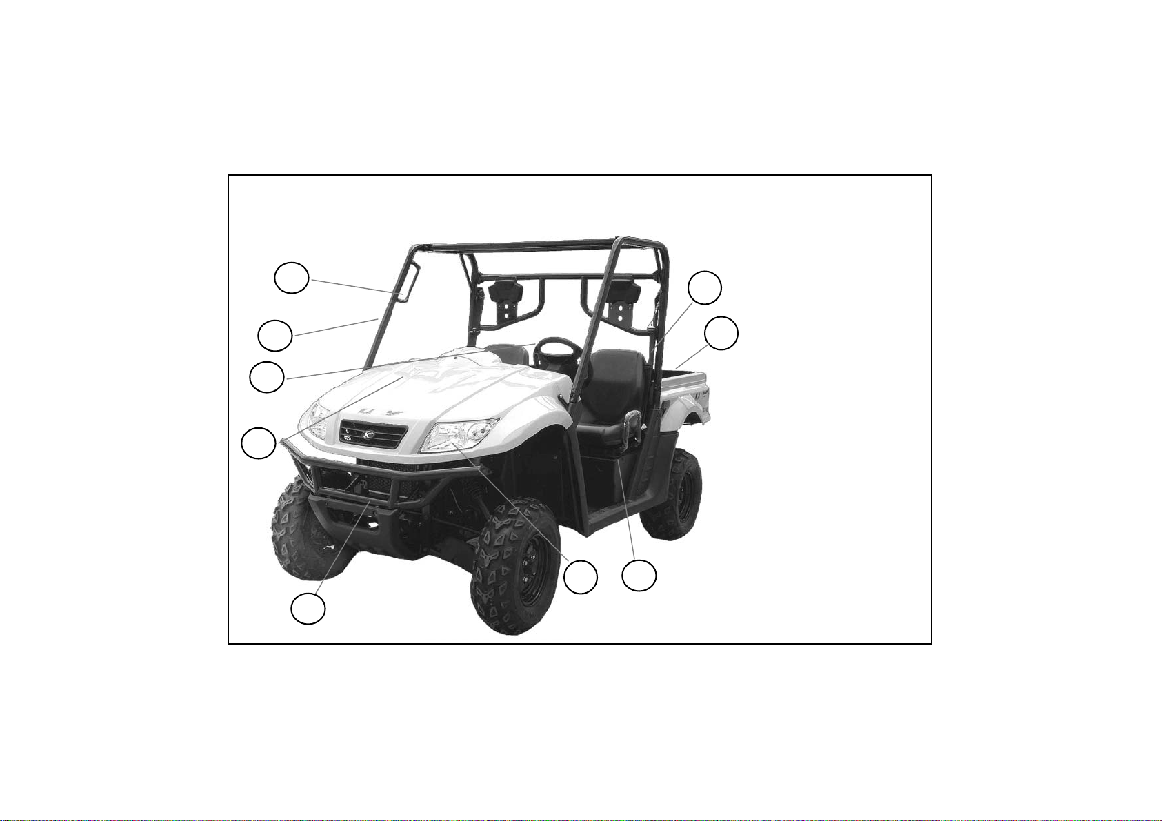
Location Of Parts (2)
11
10
12
13
14
9
8
15
7
8
07.Seat Belts
08.Cargo Bed
09.Headlights
10.Battery
11.Steering Wheel
12.Cab Frame
13.hands Bars
14.Bumper
15.Tool or Parts Box
Page 15

Location Of Parts (3)
21
16
16.Under-Hood
17.Hands Bars
18.Seat Belts
17
19.Fuel Tank Cap
20.Muffler&
Spark Arrester
21. Latch Handles
18
19
20
9
Page 16
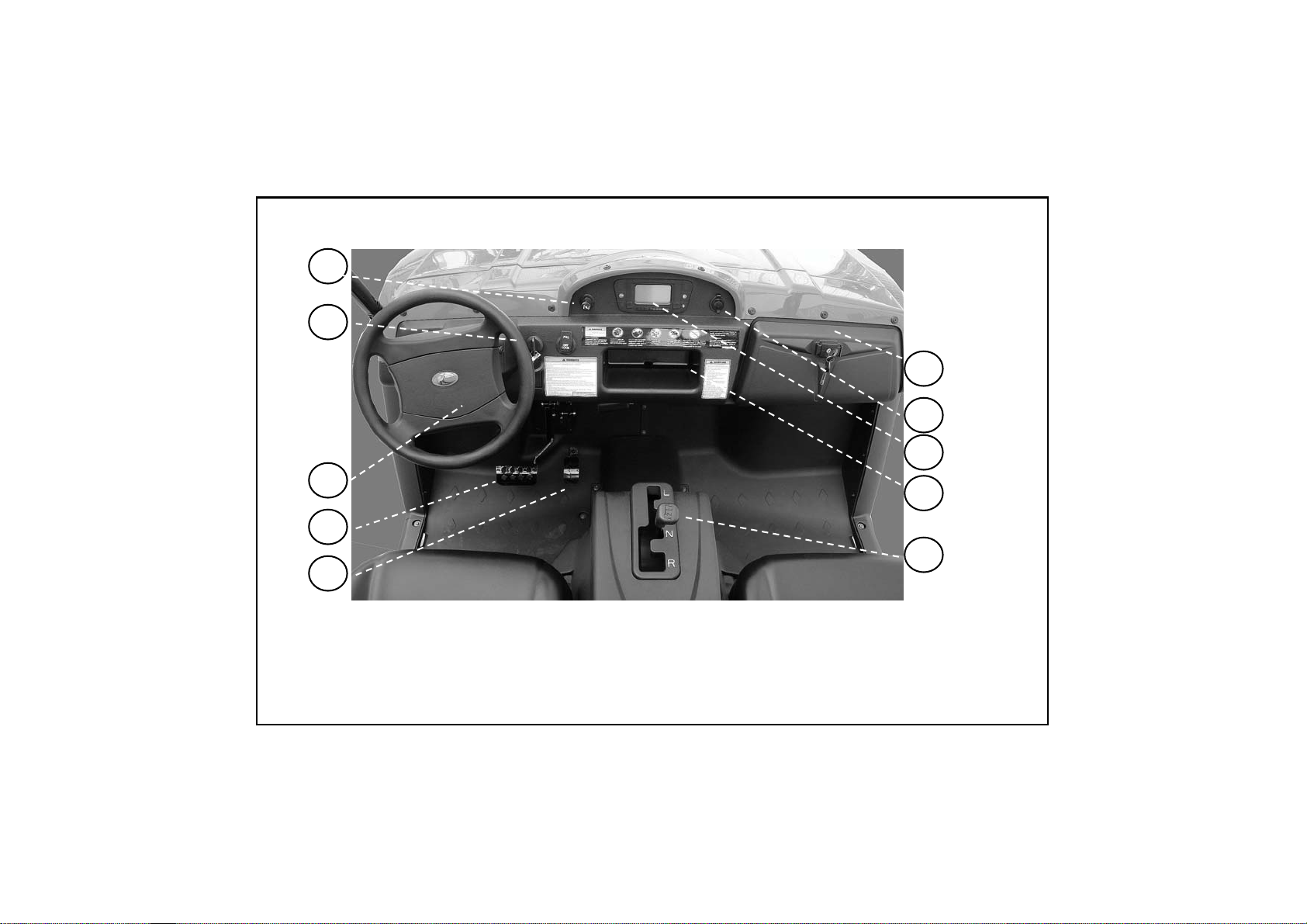
Location Of Parts(4)
25
26
20
21
22
27
28
29
20.Right Glove Compartment 21. Auxiliary Outlet 22.Speedometer
23. Center Glove Compartment 24.Shifting The Automatic Transaxle
25. Choke Knob 26.Ignition Switch 27.Steering Wheel 28.Brake Pedal
29.Throttle Pedal
10
23
24
Page 17
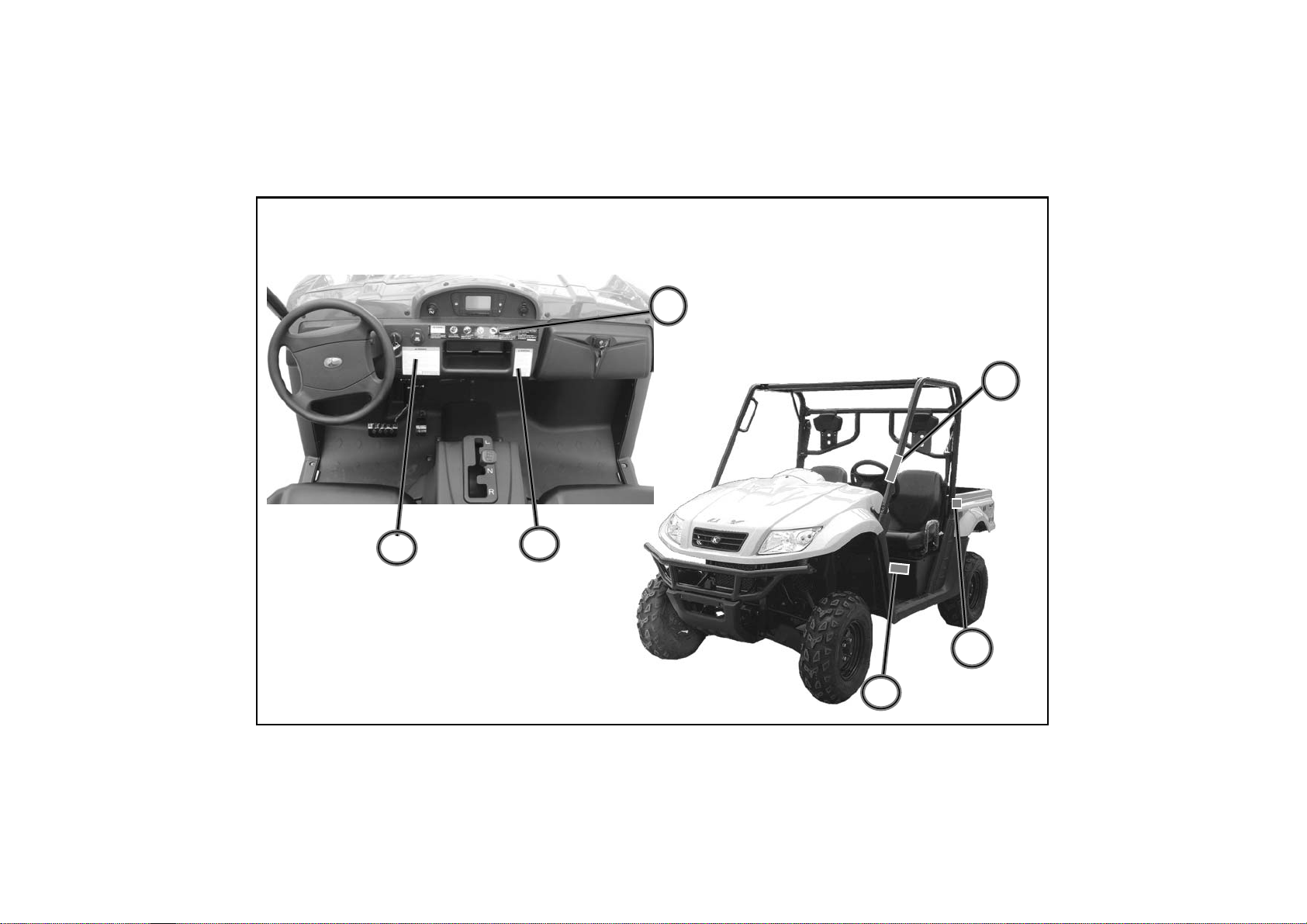
Warning Labels Location
1
4
2
3
5
6
11
Page 18

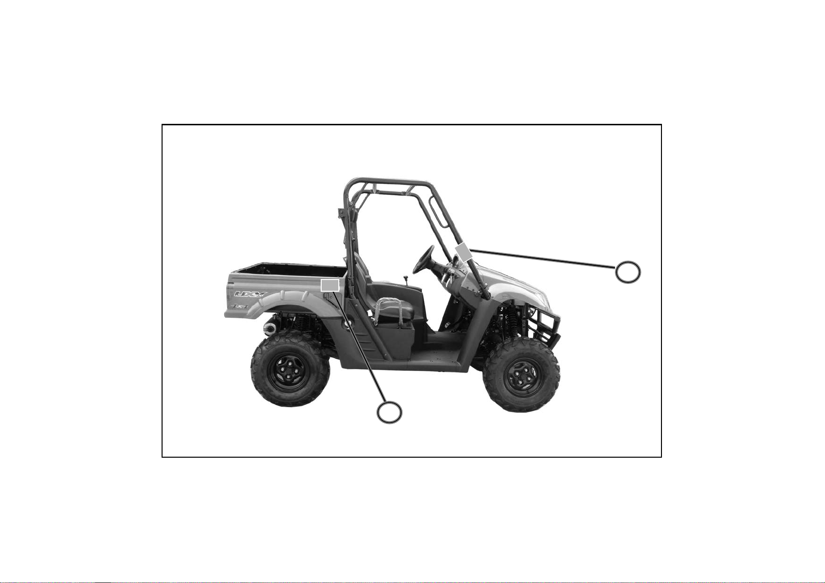
Warning Labels Location
8
7
12
Page 19
Warning Labels Location
10
9
13
Page 20

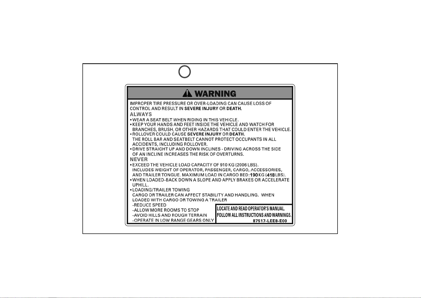
Warning Labels
1
14
Page 21

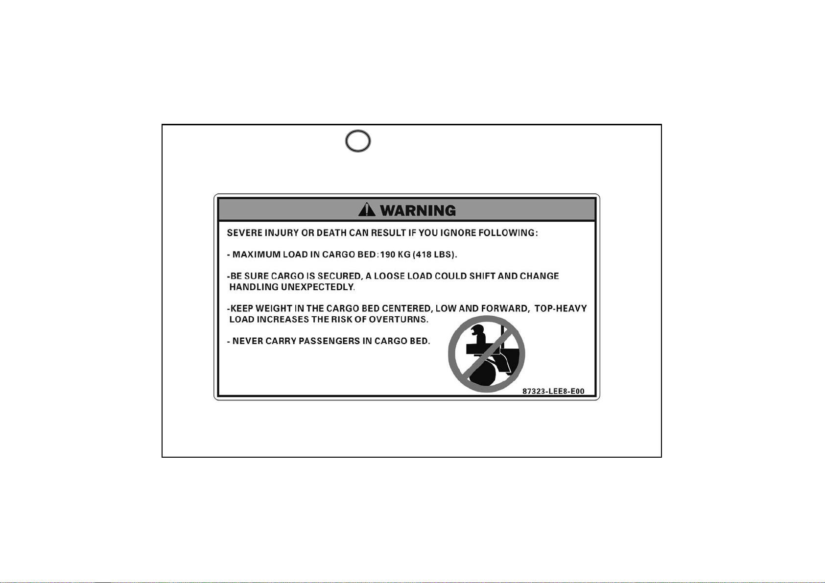
Warning Labels
1
15
Page 22
Warning Labels
1
16
Page 23
Warning Labels
1
17
Page 24
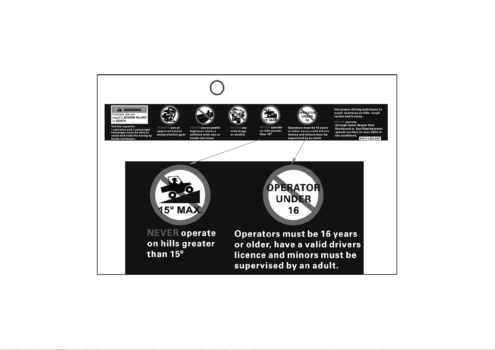
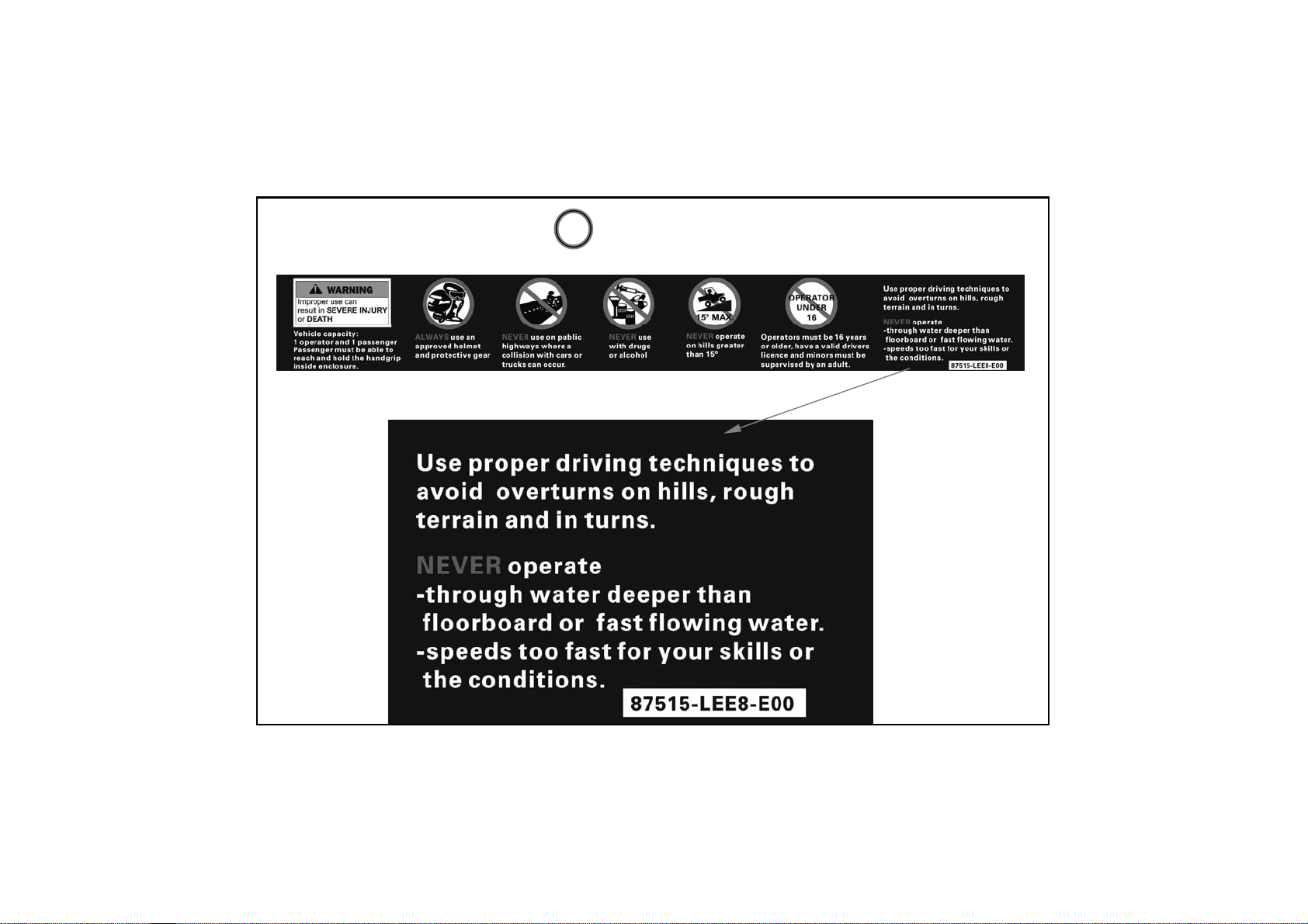
Warning Labels
2
18
Page 25

Warning Labels
3
4 9
5
10
19
Page 26

Warning Labels
6
20
Page 27
Warning Labels
7
21
Page 28

Warning Labels
8
11
22
Page 29

Features And Controls
Fuel Lever Inspection/Refilling
Check if fuel is sufficient.
If the fuel gauge pointer is E(flash).refill
nonleaded gasoline as soon as possible.
(Refilling Method)
1.Turn the tank cap counterclockwise with
hand to open the cap.
2.Use only nonleaded gasoline.
3.Turn the fuel tank cap clockwise to tighten
it.
4.Close the fuel tank cap in the reverse
order of opening.
CAUTION
!
OPEN CLOSE
Be sure to stop the engine before refilling.The gasoline level shall not exceed
the reference plate;otherwise the fuel will penetrate out.
23
Page 30

Features And Controls
Indicator Lights
The indicator lights on the console display:
1. Lower Gear 2. High Gear 3.Neutral Gear 4.Reverse Gear 5. Parking Brake
6. High Temperature Indicator Light 7.High Beam Indicator Light
7.Lock:( Differential Lock Indicator Light )
7
8
6
5
2134
24
Page 31

Features And Controls
Instruments and Indicators
1.Speedometer 2. Km/h or Mph 3. Clock 4.2WD OR 4WD 5.Fuel Gauge
6.ODO meter7. Adjust button
4
5
6
1
2
3
7
25
Page 32

Features And Controls
Operation Instruction for Multi-meter
Button A(MODE)
Button B(SET)
26
Page 33

Features And Controls
Operation Instruction for Multi-meter
(1)Press and hold button A until 2
seconds.
Shift the unit mph or km/h
Button A(MODE)
27
Page 34

Features And Controls
Operation Instruction for Multi-meter
(1)Press and hold button B until 2
seconds.
Shift function to ODO or TRIP(A)
Once again Press and hold button
B until 2 seconds change TRIP(B)
Button B(SET)
28
Page 35

Features And Controls
Operation Instruction for Multi-meter
(1)Press and hold button A&B
until 2 seconds.
Simultaneously to reset to zero
when at TRIP(A)or TRIP(B)
function.
Button A(MODE)
Button B(SET)
29
Page 36

Features And Controls
Operation Instruction for Multi-meter
(1)Press and hold button A&B
until 2 seconds . when at ODO
function.
than you can see clock position
is flash word .
Button A(MODE)
Button B(SET)
30
Page 37

Features And Controls
Operation Instruction for Multi-meter
When you seeing clock position is
flash word . You can start setting
hour item. Press button B adjust
Correct hours than Press button A
you can see the minute
flash. adjust correct minute.
Waiting for 2second .finish times
setting.
position is
Button A(MODE)
Button B(SET)
31
Page 38

Features And Controls
Auxiliary Outlet
The 12-volt receptacle has spade
connections on the back that may be used to
power an auxiliary light or other optional
accessories or lights. The connections are
behind the console,under the hood.
Choke Knob
The choke knob located on the dashboard
,to the left of the steering shaft,provides a
rich mixture for cold staring.
Pull the choke knob all the way out until it
stops and hold it to start the engine.Warm
the engine up using the choke and throttle
until the idle speed is stable,and then release
the choke knob.
Choke Knob
Auxiliary Outlet
32
Page 39

Features And Controls
Seat Removal
Pull up on front of seat it toward the front of
vehicle.
Install the seat by sliding the tabs into the
rear of the seat base.Push down firmly on
the front of the pins are fully seated into the
grommets.
Seat Belts
The UXV500 is equipped with lap-shoulder
seat belts for the operator and passenger.
33
Page 40

Features And Controls
Pillows adjust
If you want adjusting your pillows.remove the 3 screws then adjusting
you need pillow position install the 3 screws.
34
Page 41

Features And Controls
Gear Selector
1.Lower Gear
2.High Gear
3.Neutral Gear
4.Reverse Gear
To change gears,stop the vehicle and
with the engine idling, move the lever
to the desired gear. Do not attempt to
shift gears with engine speed above
idle or while the vehicle is moving.
Always place the transmission in gear
with the parking brake locked
whenever the vehicle is left
unattended.
Maintaining shift linkage adjustment is
important to assure proper
transmission function .See your dealer
if you experience any shifting
problems.
.
35
Page 42

Features And Controls
Switches
Ignition Switch
The ignition switch is a 3-position,keyoperated switch, The key can be removed
from the switch when it is in the OFF
position.
ON: Electrical circuits are on
Electrical equipment can be used.
OFF: Engine off .All electrical circuits are.
off except Acc.12V
START: Electrical starter is engaged by
holding ignition switch key in this
position. Upon release ,the key will
return to the ON position.
36
Page 43

Features And Controls
Switches
Light Switch
The ignition switch key must be in the ON
position to operate the headlights.
The switch has 4 positions.
1:Light off -At this position , light is turn off.
2: Position light - At this position , light is
turn off
3.LO Headlight Beam- When you select
this position .the low beam will illuminate.
4.Hi Headlight Beam- When you select this
position .the high beam will illuminate
.High Beam Indicator Light will turn on.
37
2
1
3
4
Page 44

Features And Controls
Switches
2WD/4WD Switch
Pushing the switch to the 4WD position or to
the 2WD position
1:2WD-At this position , LED speedometer
will show 2wd word.
2:4WD-At this position , LED speedometer
will show 4wd word.
.
38
Page 45

Features And Controls
Differential Lock lever and indicator
The front axle is equipped with a lockable
differential that allows the operator to choose
between an open differential or
a closed differential in low traction situations.
Pulling the lock lever up.
To lock the differential on the 4WD, move the 4WD
differential Button.
39
Page 46

Features And Controls
Brake Pedal(1)
Depress the brake pedal to slow or stop or
stop the vehicle.
Throttle Pedal(2)
Push the pedal down to increase engine
speed .Spring pressure returns the pedal to
the rest position when released.
Always check that the throttle pedal returns
normally before starting the engine. Make
sure there’s adequate throttle pedal free
play.
(2)
(1)
40
Page 47

Features And Controls
Parking Brake Release(3)
To release the parking brake, pull the
release handle Spring pressure helps return
the lever to the released position .make sure
the parking brake lever is functioning
properly before each operation.
41
(3)
Page 48

Features And Controls
Cargo Bed (Lift and lower the cargo bed)
Push the cargo bed release
lever to right side, then
slowly lift up cargo bed until
it stop.
Lower the cargo bed slowly
to its original position and
be sure the it is locked into
place.
To lift
To lower
Cargo Bed Lever
Maximum load in cargo bed:n
42
190 KG
Page 49

Features And Controls
Cargo Bed(Open and close the tailgate 1)
To open---(1)
Unlock the latches,and then lower
the tailgate.
(1)
Latch(x2)
43
PULL
Page 50

Features And Controls
Cargo Bed(Open and close the tailgate 2)
To close
Please the tailgate in the
original position ,and then
hook the latches.
44
Page 51

Features And Controls
Under-Hood (To Open)
Unhook the hood latches and 3PU-screws,and then slowly tilt the hood up
until it stops.
PU- Screws x3
Latch x2
45
Page 52

Features And Controls
Under-Hood (To Close)
Lower the hood slowly to its original position ,and then hook the hood
latches and Screws.
PU- Screws x3
Latch x2
46
Page 53

How to operate
Daily Safety Checks
Check the following items each day before operation.
1.Fuel→→→→→→→Enough fuel in tank,no leaks.
2.Engine Oil →→→→Oil lever between lever holes(when engine is cold),no
leaks.
3.Air Cleaner→→→→Check the restriction gauge.
4.Tires →→→→→→→Air pressure(when cold)and check tires cracks, damage
or abnormal wear.Check for any imbedded stones or other
foreign particles in tread.
Front wheel Air pressure :0.7kgf/cm²;10psi
Rear wheel Air pressure :0.98kgf/cm²;14psi
Headlight & other indicate light →→ Check the operate is normal.
Brake/Brake oil lever →→ Check the operate and oil lever is normal.
Coolant →→Coolant lever between lever lines(when engine is cold),no leaks.
Front final gear case & transmission case →→No oil leaks
47
Page 54

How to operate
Driving Safely(Driving procedures)
1.Sit in the driver’s seat and fasten the seat belt.:
2.After staring the engine and allowing it to warm up,shift the transmission
into gear.
3.Check your surroundings and determine your path of travel.
4.Release the parking brake.
5.Keeping both hands on the steering wheel, slowly depress the throttle with
your right foot and begin driving.Vehicle speed is controlled by the amount of
throttle opening & transmission shifting is automatic.
6.Drive slowly . Practice maneuvering and using the throttle and brakes on
level surfaces.
48
Page 55

How to operate
Start the engine
Note:
!
Never run the vehicle in a closed area, such as a
garage Exhaust gases contain carbon monoxide,
a colorless, odorless, poisonous gas.
Breathing exhaust gas leads to carbon monoxide
poisoning, asphyxiation, and death.
1.Wear the seat belts.
2.Set the parking brake.
3.Put the gear shift lever in the “N(neutral) position.
4.Turn the ignition switch clock wise to the START position; then when the engine
starts, release to the RUN position.
WARNING
When the engine is
already warm or the
weather is hot.
(35°C,95°F or more), do
not use the choke.
5.When the engine is cold(same as outside temperature), cannot start engine, you
will pulling the choke knob the way out until it stops and hold it.
49
Page 56

How to operate
Start the engine
!
Do not run the starting attempt. The starter motor may
overheat causing severe starter motor damage. Allow
15 seconds between starting attempts to allow the
starter motor to cool.
Braking/Stopping
Always allow plenty of room and time to stop smoothly. Sometimes quick stops
are inevitable’ so always be prepared.Whether you’re stopping quickly’ do
this:
1.Release the accelerator;then press the foot brake pedal to apply the brake.
2.If the wheels lock,release them for a second;then apply them again .On
surfaces such as ice,mud or loose gravel’ pump the brake pedal rapidly.
3.Never ride the brake .Even maintaining minimal pressure on the brake pedal
will cause the brake pads drag on the disc and may overheat the brake fluid.
CAUTION
50
Page 57

How to operate
Parking
Parking involves flowing the previous rules for braking;then :
1.After the vehicle stops,shift into neutral gear.
2.Set the parking brake.
3.Turn off the ignition key.
4.If you have to park on the hill,shift to low range,set the parking brake,and
block the wheel on the downhill side.
Driving downhill
Always drive straight down the hill and always avoid hills sleeper than 15°
1.Keep both hands on the wheel.
2.Prior to descending the hill,shift into range and release the accelerator to
allow maximum engine brake.Do not use 4 wheel drive when descending a
hill.Engine braking can cause the front wheels to slide reducing steering control.
51
Page 58

How to operate
Driving uphill
whenever travel straight uphill, follow these precautions:
1.Always travel straight uphill.
2.Avoid steep hills(15° maximum)
3.Keep both feet on the floor.
4.Proceed at a steady rate of speed and throttle opening.
NEVER OPERATE UP OR
DOWN HILLS STEEPER
THAN 15°
52
15° maximum
Page 59

How to operate
Crossing water
UXV500 can only operate in water up to its floorboard.Stay away from fast
moving rivers. This vehicle’s tires can be buoyant.In deep water,the vehicle
may lose traction due to floating.
1.Physically check the depth and current of the water, especially if you can not
see the bottom.Also,check for boulders,logs,or any other hidden obstacles.
2.Keep speed slow while maintaining momentum.
3.Make sure you have a way out on the other side of the water.
4.Once you have cleared the water,briefly apply the brakes to make sure they
work.
53
Page 60

How to operate
Driving in reverse
Follow these guidelines when operating in reverse:
1.Back slowly.
2.Apply the brakes lightly for stopping.
3.Avoid turning at sharp angles.
4.Always avoid backing downhill.
5.Never open the throttle suddenly while backing.
6. Always inspect left and right fields of vision before backing.
54
Page 61

Emission Control System
Crankcase Emission Control System
This engine is equipped with a closed crankcase system .
Blow-by gases forced back to the comb7ustion chamber by the intake s7ystem.
The system does not allow the blow-b7y gases to enter the atmosphere.
Exhaust Emission Control System
The emissions from the exhaust of this vehicle are controlled by engine
design,including factory-set fuel delivery and ignition.KYMCO Exhaust
Emission Control System including
second air supply system & catalyzer
any kymco
design.
convert system.please do not change
Noise Exhaust Emission Control System
Do not modify the engine ,intake or exhaust components, as doing so may
affect compliance with state and local noise level requirements.
55
Page 62

Emission Control System
Spark Arrestor
Your UXV 500 has a spark arrestor.
The spark arrestor be installed and functional when the vehicle operated on
public lands.
Remove method
remove 3 screws
56
Clean method
Use the iron brush cleaning
carbon on the spark arrestor
Page 63

Maintenance And Lubrication
Engine Oil
Always check and change the oil at the OWNER MANUAL standard intervals.
The oil tank is located under the seat.
1.Position the vehicle on the surface.
2.Start the engine and let it idle for 20~30seconds.
3.Stop the engine and remove the seat.
4.Add fresh oil into the oil tank .
Make sure the engine oil at the specified level.
Add oil as ne cessary. Check for leaks.
Oil quantity:
Engine oil:
Periodic oil change:
3 L (2.64 Imp qt, 3.18 US qt)
Total amount:
3.6 L (3.17 Imp qt, 3.82 US qt)
Recom me n ded engine o il classification: API
Service SJ typ e or higher
57
0
1 0
SAE 5W
0
-1 0
30
0
50
0
SAE 10W 30
SAE 10W 40
0
0
10
0
0
70
90
-
-
SAE 20W 40
SAE 20W 50
20
-
-
0
30
0
0
0
110 F
0
40 C
Page 64

Maintenance And Lubrication
ENGINE OIL
1.Engine oil level measurement
A. Place the machine on a level place.
B. Warm up the engine for several minutes and stop it.
C. Check the oil level through the inspection window.
D. The oil level should be between the maximum (H) and minimum (L) marks.
If the level is low, add oil to raise it to the proper level.
NOTE:
Wait a few minutes until the oil level settles
before checking.
H
L
58
Page 65

Maintenance And Lubrication
Engine oil replacement and oil filter cleaning
1. Place the machine on a level place.
2. Warm up the engine for several minutes and stop it.
3. Place a container under the engine.
4. Remove the oil fill cap (1) and oil fill cap
(2) to drain the oil.
CAUTION:
Be sure no foreign material enters the
crankcase.
CAUTION:
When removing the oil filter cap, the
compression spring, oil strainer and O-ring
will fall out. Take care not to lose these
parts.
(2) oil filter cap
59
(1) oil fill cap
Page 66

Maintenance And Lubrication
NOTE:
Skip steps E to I if the oil filter cartridge is not
being replaced.
Remove the oil filter cartridge with an oil cartridge wrench.
oil filter
remove lock
60
Page 67

Maintenance And Lubrication
BRA KE FLUID INSPECTIO N
Check if the fluid level is below the lower level
mark through the inspection window.
W ARNING
POTENTIAL HAZARD
Brake fluid contacting the skink or eyes.
WH AT CAN HAPPEN
May cause irritation.
HOW TO AVOID THE HAZARD
Avoid contacting brake fluid with the skin
or eyes. In case of contact, flush thoroughly
with water and call a doctor if your eyes
were exposed.
61
(1) Lower level mark
(2) Upper level mark
Page 68

Maintenance And Lubrication
Air Cleaner
Remove the center cover screws and center cover
Remove
Shifting The Automatic Transaxle bolt.
62
Page 69

Maintenance And Lubrication
Air Cleaner
Remove air cleaner cover screws.
Remove air cleaner filter
63
Page 70

Maintenance And Lubrication
Air Cleaner
Clean the air cleaner filter
64
Page 71

Maintenance And Lubrication
Battery remove
1. Make sure the ignition switch is OFF.
2. Remove the under-hood hook& pu bolts.
3. Remove the battery cover screws.
4. Disconnect the negative (-) terminal lead (1)
from the battery first, then disconnect the
positive (+) terminal lead (2).
5. Remove the battery.
Battery installation
1. Install in the reverse order of removal.
2. After installing the battery, check to see if
the battery cables are routed correctly.
NOTE:
First connect the positive (+) cable and then
negati ve (-) cable to avoi d short circu it.
(1)(2)
65
Page 72

Maintenance And Lubrication
Fuse Replacement
The fuse box stored in the battery compartment.
To replace a fuse:
1. Make sure the ignition switch is OFF.
2. Remove the under-hood hook& pu bolts
3. Open the fuse box cap.
4. Pull the old fuse out of the fuse holder.
5. Push the new fuse in to the fuse holder.
6. Close the fuse box cap and install seat.
CAUTION:
To prevent accidental short-circuiting, turn
off the main switch when checking or
replacing a fuse.
(1) (2) (3) (4) (5) (6)
(6)FAN MOTER---------15A
(5)IGNITION--------------15A
(4)LIGHT------------------15A
(3)DC12VPOWER------15A
(2)SPARE-----------------15A
(1)SPARE-----------------30A
66
Page 73

Maintenance And Lubrication
Cooling System Inspection
1. Remove the under-hood hook& pu
bolts
2. Check the coolant level in the
coolant reservoir when the engine is
cold as the coolant level will vary with
engine temperature. The coolant level
should be between the maximum and
minimum marks.
3. If the level is low, remove the coolant
reservoir cap, and then add coolant or
distilled water to raise it to the
specified level.
CAUTION:
Hard water or salt water is harmful to the
engine. You may use distilled water if rou
can n ot get so ft wa ter.
NOTE:
1. If water is added, have a KYMCO dealer
check the antifreeze content of the coolant
as soon as possible.
2. The radiator fan operation is completely
automatic. It is switched on or off according
to the coolant temperature in the radiator.
FULL
LOW
67
Page 74

Maintenance And Lubrication
WHEEL REMOVEL
1.Elevate the wheel by placing a suitable
stand under the frame.
2.Remove the nuts from the wheel.
3. Remove the wheel assembly.
(1)
WHEEL INSTALLATION
When reinstalling a wheel, tighten the wheel
nuts in a crisscross(rather than a
circular)pattern.Be sure the tapered a side of the
wheel nuts(1)face the wheel rim(2).
Wheel nut torque:
Front:55 N-m(5.5 kgf-m,40 lbf-ft)
Rear:55 N-m(5.5 kgf-m, 40 lbf -ft)
Be sure the tapered side of the wheel nuts(1)
face the wheel rim(2).
OK
(2)
(1)
68
(1) Wh eel nut (2) Wheel rim
Page 75

Maintenance And Lubrication
NOTE:
The arrow mark on the tire must point
toward the rotating direction of the wheel.
(1)
(1) A rrow mark
POTENTIAL HAZARD
Installing wheels improperly.
WHAT CAN HAPPEN
A wheel may come loose, possibly leading
to an accident.
HOW TO AVOID THE HAZARD
Car efully follow the in structions in t his
Owner's Manual when installing.
W ARNING
69
Page 76

Maintenance And Lubrication
n
e
e
Before installing the spark plug, measure the
SPARK PLUG INSPECTION
The spark plug is an important engine
component and is easy to inspect. The conditio
of the spark plug can indicate the condition of
the engine.
For example, a very white center el ectrode
porcelain color could indicate an intake air leak
or carburetion problem for that cylinder. Do not
attempt to diagnose such problems yourself.
Instead, take the machine to a KYMCO dealer.
You should periodically remove and inspect the
spark plug because heat and dep osits wil l caus
the spark plug to slowly break down and erode.
If electrode erosion becomes excessive, you
should replace the spark plug with one of the
proper type.
electro de gap with a feeler gauge and adjust to
specification.
Spark plug gap:
0.9 mm ( 0 .0 2 4 ~0 .0 2 8 i n )
(A)
(A) Spark plug gap
W h e n in s ta l l i n g th e sp a rk pl u g , al w a y s cle a n th
ga s ke t s u rfa c e a n d us e a ne w ga s ke t. Wip e o ff
an y gr i me fro m th e th re a d s an d ti g h te n to the
specified torque.
Standard spark plug (NGK): CR7E
Tighten ing torque:
Spark plug:
17 .2 N - m (1.7 2 kg f- m, 1 3 l b f- ft)
70
Page 77

Maintenance And Lubrication
Tool kit
The tool kit put down location at
The tool kit includes the following items:
(1) Hexagon wrench
(2) Spark plug wrench
(3) 8/12;10/14;17/19 mm wrench
(4) Screwdriver
(5) Screwdriver handle
(6) Tool bag
(7)Air pressure gauge
Right Glove Compartment .
71
(6)
(7)
(4)
(1) (2)(3) (5)
Page 78

Specifications
MO DEL UXV500(OFF RO AD)
DIMENSIONS:
OVERAL L L ENGTH
OVERAL L W IDTH
OVERAL L HEIG HT
SEAT HEIG HT
WHEELBASE
GRO UND CLEARANCE
MINMUN. TURNING RADIUS
BASIC WEIGHT:
WITH OIL AND FULL FUEL TANK
MAX. CARGO BED LOAD
DRY W EIGHT
MAX. W EIG HT CAPACITY
ENGINE:
ENGINE TYPE
CY LINDER ARRANGEMENT
BOREx STROKE
ACTUAL DISPL ACEM ENT
COMPRES SIO N RATI O
STARING SYSTEM
LUBRICATI ON SYSTEM
2870MM
1500MM
1850MM
805MM
1910MM
310MM
4060MM
560KG
190KG
525KG
350KG
4 -STRO KE,DO HC
SINGL E CYLINDER
92x 75MM
498.5CC
10.5:1
ELECTRIC STARTER
WET SUMP
72
Page 79

Specifications
MO DEL UXV500(OFF RO AD)
ENGINE G EAR BOX:
CAPICITY/EXCHANGE/TYPE
FRONT GEAR BOX:
CAPICITY/EXCHANGE/TYPE
REAR GE AR BOX
CAPICITY/EXCHANGE/TYPE
AIR FILTER:
FUEL:
TYPE
FUEL TANK CAPACITY
CA RBURETOR:
TYPE/MAN UFACTURER
SPARK PLUG:
TYPE/MAN UFACTURER
SPARK PLUG
CLUTH TYPE:
3.6L,5W-30
275ML,(SAE80#)
250ML,(SAE80#)
SPONGE ELEMENT
UNLEADED G ASOLI NE
32L
LEE8/ KYM CO
CR7E-NGK
0.9MM
WET CENTRI FUGA L AUTO M A TIC
73
Page 80

Specifications
MO DEL UXV500(OFF RO AD)
TRANSMISSION:
PRIMARY REDUCTION SYSTEM
SECONDARY REDUCTION SYSTEM
TRANSMI SSIO N TYPE:
TIRE:
TYPE
SIZE(FRONT)
SIZE(REAR)
WHEEL MATERIAL
PRESSURE FR/RR
BRA KES:
SYSTEM FRONT AND REAR UNIFI ED
TYPE(FRO NT) DUAL DISC BRAKE
TYPE(REAR) SINGLE DISC BRAKE
OPERATI ON FOOT O PERATION
SUSPENSION:
FRONT SUSPENSIO N DOUBLE WI SHBONE
REAR SUSPENSION DOUBLE WISHBONE
SHOCK ABSORBER: COI L SPRI NG/ OI L DAM PER
V-BELT
SHAFT DRIVE
V-BELT AUTOM ATI C
TUBELESS
25x8-12
25x10-12
STEEL
0.7/0. 98( k gf / cm2) O R 10/14 psi
74
Page 81

Specifications
MO DEL UXV500(OFF RO AD)
WHEEL T RAVEL:
FRONT WHEEL TRAVEL
REAR WHEEL TRAVEL
ELETRICAL:
IG NITI O N SYSTEM
GENERATO R S YSTE M
BATTERY TYPE
BATTERY CAPACI TY
HAEDLIGHT TYPE:
BULB VOLT AGE
WATTAGE X QUANTITY:
HAEDLIGHT: 12V35/35W*2
NO. PLATE LIGHT NONE
REAR LIGHT 12V21/5W * 2
INDICAT ORS FR /RR DI RE CT IO N NONE
BRAKE LIG HT 12V21/ 5 W * 2
POSITI O N LIGHT 12V21/5W* 2
190MM
190MM
DC, CDI
A.C.MAGNETO
MF-VTX20L
12V18AH
HS1
75
Page 82

Specifications
MO DEL UXV500(ON ROAD)
SPECIFIED FUSES:
MAIN FUSE 30A
FAN MOTER
IGNITION
LIGHT
DC12VPOWER
SPARE
SPARE
15A
15A
15A
15A
15A
30A
76
Page 83

PERIODIC MAINTENANCE/LUBRICATION
ITEM
ROUTINE
!
Engine oil
*Oil strainer
Engine oil filter cartridge
Final gear oil
Differential gear oil
Air filter element
(for engine and *V-belt
compartment)
*Carburetor
*Cylinder head cover
breather system
Spark plug
*Fuel line
*Valves
Replace (Warm engine before draining).
!
Clean.
!
Replace if necessary.
!
Replace
!
Check oil level/oil leakage
!
Replace every 12 months.
!
Check oil level/oil leakage
!
Replace every 12 months.
!
Clean. (More often in wet or dusty areas.)
!
Replace if necessary.
!
Check idle speed/starter operation.
!
Adjust if necessary.
!
Check breather hose for cracks or damage.
!
Replace if necessary.
!
Check condition.
!
Adjust gap and clean.
!
Replace if necessary.
!
Check fuel hose for cracks or damage.
!
Replace if necessary.
!
Check valve clearance.
!
Adjust if necessary.
WHICHEVER COMES FIRST
mi
Km
MONTH
INITIAL EVERY
100
150
600
1200
1000
2000
1612
(Cont’d)
77
Page 84

ITEM
*Brake
*Coolant
*V-belt
*Exhaust system
Spark arrester
*Wheels
*Wheel bearings
*Steering system
*Drive shaft boots
*Suspension
WHICHEVER COMES FIRST
ROUTINE
!
Check operation and brake fluid.
!
Replace brake pad if necessary.
!
Check coolant leakage.
!
Replace if necessary.
!
Replace coolant every 24 months.
!
Check operation.
!
Replace if damage or excessive wear.
!
Check leakage.
!
Retighten if necessary.
!
Replace gasket if necessary.
!
Clean
!
Check balance/damage/runout.
!
Replace if necessary.
!
Check bearing assembly for looseness/damage.
!
Replace if damaged.
!
Check operation.
!
Replace if damaged.
!
Check toe-in.
!
Adjust if necessary.
!
Check operation.
!
Replace if damaged.
!
Check operation.
!
Correct if necessary.
mi
Km
MONTH
INITIAL EVERY
100
150
600
1200
1000
2000
1
6
12
78
(Cont’d)
Page 85

ITEM
WHICHEVER COMES FIRST
ROUTINE
*Knuckle shafts/
Steering shaft
*Fittings and Fasteners
* : It is recommended that these items be serviced by a KYMCO dealer.
** : Lithium soap base grease.
!
Lubricate every 6 months.
!
Check all chassis fittings and fasteners.
!
Correct if necessary.
mi
Km
MONTH
INITIAL EVERY
100
150
600
1200
1000
2000
1
6
12
79
Page 86

Maintenance Record
Page 87

Maintenance Record
Page 88

Maintenance Record
Page 89

Maintenance Record
Page 90

Maintenance Record
Page 91

Maintenance Record
Page 92

By KWANG YANG Motor Co., Ltd.
Frist Edition, Oct 2007
All rights reserved. Any reproduction or
unauthorized use without the written permission of
KWANG YANG Motor Co., Ltd.
is expressly prohibited.
T200-UAA0AA-US
Page 93

KWANG YANG MOTER CO .,LTD
NO.35 Wan Hsing Street,San Min District
Kaohsiung, Taiwan, Republic Of China
Telephone : 886-7-3822526
Fax : 886-7-3950021
Printed in Taiwan
 Loading...