


19. SWITCHES/HORN/FUEL UNIT/THERMOSTATIC SWITCH
/TEMPERATURE GAUGE/INSTRUMENTS/LIGHTS
19-0
Bet & Win
19
__________________________________________________________________________________
__________________________________________________________________________________
__________________________________________________________________________________
__________________________________________________________________________________
__________________________________________________________________________________
SWITCHES/HORN/FUEL UNIT/THERMOSTATIC
SWITCH/TEMPERATURE GAUGE/ INSTRUMENTS/LIGHTS
__________________________________________________________________________________
ELECTRICAL EQUIPMENT LAYOUT------------------------------ 19-1
SERVICE INFORMATION -------------------------------------------- 19-2
TROUBLESHOOTING ------------------------------------------------- 19-2
SWITCHES -------------------------------------------------------------- 19-3
HORN INSPECTION --------------------------------------------------- 19-5
FUEL UNIT-------------------------------------------------------------- 19-5
THERMOSTATIC SWITCH ------------------------------------------- 19-6
TEMPERATURE METER---------------------------------------------- 19-6
INSTRUMENTS--------------------------------------------------------- 19-7
LIGHTS ------------------------------------------------------------------ 19-8
HEATER WIRING DIAGRAM ---------------------------------------- 19-9
19
19. SWITCHES/HORN/FUEL UNIT/THERMOSTATIC SWITCH
/TEMPERATURE GAUGE/INSTRUMENTS/LIGHTS
19-1
Bet & Win
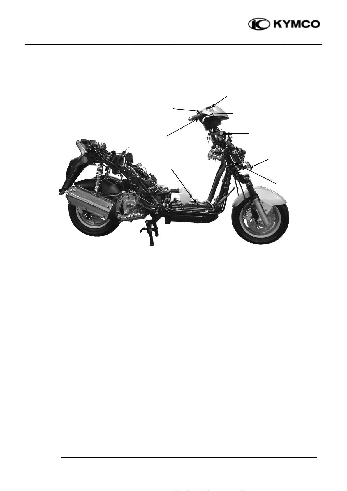
ELECTRICAL EQUIPMENT LAYOUT
Turn Signal Switch
Stop Switches
Horn Button
Headlight
Dimmer Switch
Fuel Unit
Starter Button
Horn
Ignition Switch
Instruments
Thermostatic
Switch
Headlight
Switch

19. SWITCHES/HORN/FUEL UNIT/THERMOSTATIC SWITCH
/TEMPERATURE GAUGE/INSTRUMENTS/LIGHTS
19-2
Bet & Win
SERVICE INFORMATION
GENERAL INSTRUCTIONS
• After installation of each switch, a continuity check must be performed. A continuity check can
usually be made without removing the part from the motorcycle.
TESTING INSTRUMENT
Electric tester
SPECIAL TOOL
Fuel unit wrench
TROUBLESHOOTING
Lights do not come on when ignition Temperature gauge does not register
switch is “ON” correctly
• Burned bulb • Faulty temperature gauge
• Faulty switch • Faulty thermosensor
• Poorly connected, broken or shorted wire • Broken or shorted wire between
temperature gauge and thermosensor
Fuel gauge pointer does not move or
register correctly
• Faulty fuel gauge
• Faulty fuel unit
• Poorly connected wire between fuel
gauge and fuel unit
• Fuse burned out
SPECIFICATIONS
Fuse 20A
Headlight bulb 12V 35W/35W
Turn signal light bulb 12V 10W
Stoplight/taillight 12V 21/5W
License plate light 12V 5W
Instrument light 12V 1.7W
Position light 12V 5W
Turn signal indicator light 12V 3.4W

19. SWITCHES/HORN/FUEL UNIT/THERMOSTATIC SWITCH
/TEMPERATURE GAUGE/INSTRUMENTS/LIGHTS
19-3
Bet & Win
SWITCHES
IGNITION SWITCH INSPECTION
Remove the frame front covers. (!2-5)
Disconnect the ignition switch wire couplers.
Check for continuity between the wire
terminals.
Color
Position
Red2
Black/Wh
ite
Green
Black
PARK
LOCK
○
○
OFF
○
○
ON
○
○
HEADLIGHT SWITCH INSPECTION
Remove the frame front covers. (!2-5)
Disconnect the headlight switch wire
couplers. Check for continuity between the
wire terminals.
Color
Position
White /
Blue
Brown/
Blue
Brown
n
P○○
H○○
○
STARTER SWITCH INSPECTION
Remove the frame front covers. (!2-5)
Disconnect the starter switch wire couplers.
Depress the starter button and check for
continuity between the wire terminals.
Color
Position
Yellow/Red
Green
FREE
PUSH
○
○
ENGINE STOP SWITCH
Remove the front upper cover. (!2-5)
Disconnect the wire couplers.
Checks for continuity between the engine
stop switch wire terminals.
Color
Position
Yellow/Black
Gray
OFF
ON
○
○

19. SWITCHES/HORN/FUEL UNIT/THERMOSTATIC SWITCH
/TEMPERATURE GAUGE/INSTRUMENTS/LIGHTS
19-4
Bet & Win
HORN BUTTON INSPECTION
Remove the frame front covers. (!2-5)
Disconnect the horn wire couplers.
Depress the horn button and check for
continuity between the wire terminals.
Color
Position
Light Green
Brown/Blue
FREE
PUSH
○
○
TURN SIGNAL SWITCH INSPECTION
Remove the frame front covers. (!2-5)
Disconnect the turn signal switch wire
couplers and turn on the turn signal switch.
Check for continuity between the wire
terminals.
Color
Position
Light Blue/
White
Gray
Orange/
White
L○○
N
R
○
○
DIMMER SWITCH INSPECTION
Remove the frame front covers. (!2-5)
Disconnect the headlight dimmer switch wire
couplers.
Turn on the dimmer switch and check for
continuity between the wire terminals.
Color
Position
White/
Blue
Blue
White
Brown/
Blue
LO
○
○
HI
○
○
PASSING
○
○
STOP SWITCH INSPECTION
Remove the frame front covers. (!2-5)
Disconnect the front/rear stop switch wire
couplers.
Check for continuity between the wire
terminals when the front brake lever is
applied.
Color
Position
Brown/Blue
Green/Yellow
FREE
APPLY
○
○
Horn Button
Stop Switch
Turn Signal Switch
Dimmer Switch
PASSING

19. SWITCHES/HORN/FUEL UNIT/THERMOSTATIC SWITCH
/TEMPERATURE GAUGE/INSTRUMENTS/LIGHTS
19-5
Bet & Win
HORN INSPECTION
Remove the front upper cover. (!2-5)
Disconnect the horn wire couplers.
The horn is normal if it sounds when a 12V
battery is connected across the horn wire
terminals.
FUEL UNIT
FUEL UNIT INSPECTION
Remove the fuel unit.
Disconnect the fuel unit wire connectors.
Measure the resistance between the fuel unit
wire terminals with the float at upper and
lower positions.
Wire Terminals
Upper
Lower
Y/W_ G
33_ 45W
500_ 850
W
L/W_ G
400_ 700
W
100_ 200
W
Y/W_ L/W
450_ 750
W
450_ 750
W
FUEL METER INSPECTION
Connect the fuel unit wire connectors and
turn the ignition switch “ON”.
Check the fuel meter LCD for correct
indication by moving the fuel unit float up
and down.
Float Position
LCD Display
Upper
Much (Full)
Lower
Less (Empty)
Wire Terminals
LCD Display
Y/W_ G
From Much to Less
L/W_ G
From Less to Much
The fuel meter is normal if it operates as
above indicated. If not, check for loosely
tightened nuts, poorly connected terminals or
shorted wires.
Fuel Unit
Before performing the following test,
operate the turn signals to determine that
the battery circuit is normal.
*
Horn
Lower
Upper
Upper
Fuel Full
Lower
. Fuel Empty

19. SWITCHES/HORN/FUEL UNIT/THERMOSTATIC SWITCH
/TEMPERATURE GAUGE/INSTRUMENTS/LIGHTS
19-6
Bet & Win
THERMOSTATIC SWITCH
INSPECTION
Remove the front covers. (!2-5)
Start and run the engine to make the water
temperature reaches 85℃_ 90℃
and check if the cooling fan motor operates.
Lower the water temperature to 85℃ and
check if the fan motor stops.
If the fan motor does not start, disconnect
the wires from the thermostatic switch and
then connect a jumper wire between the
wire harness and thermosensor wires (black
and green wires).
Turn the ignition switch ON. The
thermostatic switch is faulty if the cooling
fan motor runs properly.
If it does not start, check for voltage
between the fan motor coupler wire
terminals (black_ green).
If there is no voltage, check for the
following:
• Blown or faulty fuse
• Loose terminals or connectors
• Shorted wire in the wire harness
TEMPERATURE METER
Disconnect the wire from the thermosensor
and ground it to the engine.
Turn the ignition switch ON.
The fifth or sixth cell of the temperature
LCD is twinkling.
HEATER CONTROLER UNIT
INSPECTION
1. Open ignition switch to check if the
black wire of it is enough voltage.
2. Put the heater controller unit in
refrigerator. Start engine after keeping the
temperature under 10± 4℃ .
3. Check if the yellow wire of heater
controller unit has output voltage.
Start engine and if the temperature of heater
controller unit is under 10± 4℃ . Check if
the white/blue wire of heater controller unit has
outp ut voltage. If it has not any voltage. It is
damaged.
Wire
Thermostatic Switch
Do not leave the thermosensor wire
grounded for longer than 5 seconds or
the temperature gauge will be damaged.
*

19. SWITCHES/HORN/FUEL UNIT/THERMOSTATIC SWITCH
/TEMPERATURE GAUGE/INSTRUMENTS/LIGHTS
19-7
Bet & Win
INSTRUMENTS
REMOVAL
Remove the front upper cover. (!2-5)
Disconnect the instrument wire couplers and
connectors.
Disconnect the speedometer cable.
Remove the four instrument cover and leg
shield screws.
Remove the instruments.
DISASSEMBLY/ASSEMBLY
Remove the three instrument holder nuts.
Remove the holder.
Remove the four screws to disassemble the
instruments and instrument cover.
Assemble the instruments in the reverse order
of disassembly.
INSTALLATION
The installation sequence is the reverse of
removal.
Wire Couplers
Speedometer Cable
Screws
Screws

19. SWITCHES/HORN/FUEL UNIT/THERMOSTATIC SWITCH
/TEMPERATURE GAUGE/INSTRUMENTS/LIGHTS
19-8
Bet & Win
LIGHTS
HEADLIGHT BULB REPLACEMENT
Remove the front upper cover. (!2-5)
Disconnect the headlight and turn signal light
wire couplers.
Remove the rubber boot from the bulb socket.
Remove the bulb socket and replace the bulb.
Install the bulb socket, aligning the bulb
socket tab with the groove.
Install the rubber boot.
Install the front cover in the reverse order of
removal.
FRONT POSITION LIGHT BULB
REPLACEMENT
Remove the front upper cover. (!2-5)
Disconnect the headlight and turn signal light
wire couplers.
Remove the bulb sockets by turning them
counterclockwise.
Remove the bulbs and replace them with new
ones.
FRONT TURN SIGNAL LIGHT BULB
REPLACEMENT
Remove the one screw attaching the turn
signal light shell and remove the light shell.
Remove the turn signal fixer two screws.
Remove the bulb protector screw.
Remove the bulb and replace with a new one.
TAILLIGHT/REAR TURN SIGNAL LIGHT
BULB REPLACEMENT
Remove the rear protective cover. (!2-3)
Remove the two screws attaching the rear
light shell and remove the light shell.
Remove the bulbs and replace with new ones.
The installation sequence is the reverse of
removal.
Screws
Front Position Light Bulb
Wire
Bulb Socket
Protector
Wire
Fixer

19. SWITCHES/HORN/FUEL UNIT/THERMOSTATIC SWITCH
/TEMPERATURE GAUGE/INSTRUMENTS/LIGHTS
19-9
Bet & Win
HEATER WIRING DIAGRAM
 Loading...