

Kymco MO BW250 Service Manual - chap11 (albero motore)

11. CRANKCASE/CRANKSHAFT
11-0
Bet & Win 2 50
11
__________________________________________________________________________________
__________________________________________________________________________________
__________________________________________________________________________________
__________________________________________________________________________________
__________________________________________________________________________________
CRANKCASE/CRANKSHAFT
__________________________________________________________________________________
SCHEMATIC DRAWING ---------------------------------------------- 11-1
SERVICE INFORMATION -------------------------------------------- 11-2
TROUBLESHOOTING ------------------------------------------------- 11-2
CRANKCASE SEPARATION ----------------------------------------- 11-3
CRANKSHAFT INSPECTION----------------------------------------- 11-4
CRANKCASE ASSEMBLY -------------------------------------------- 11-5
11
11. CRANKCASE/CRANKSHAFT
11-1
Bet & Win 2 50
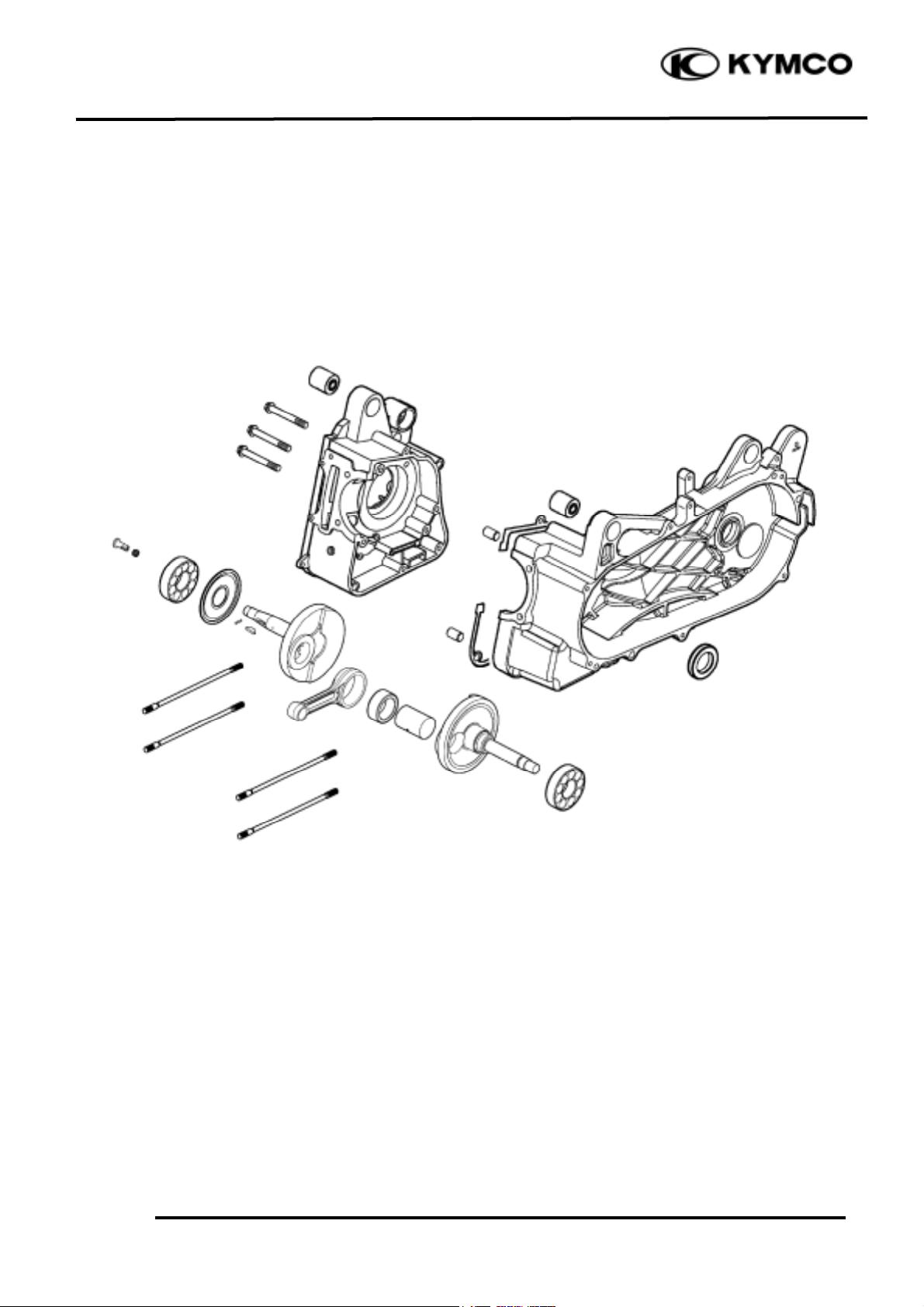
SCHEMATIC DRAWING
11. CRANKCASE/CRANKSHAFT
11-2
Bet & Win 2 50
SERVICE INFORMATION
GENERAL INSTRUCTIONS
• This section covers crankcase separation to service the crankshaft. The engine must be removed
for this operation.
• When separating the crankcase, never use a driver to pry the crankcase mating surfaces apart
forcedly to prevent damaging the mating surfaces.
• When installing the crankcase, do not use an iron hammer to tap it.
• The following parts must be removed before separating the crankcase.
Cylinder head (!6-4)
Cylinder/piston (!7-3)
Right crankcase cover/drive and driven pulley (!8-3)
A.C. generator/starter clutch (!10-3)
Rear wheel/rear shock absorber (!15-4)
Starter motor (!19-3)
Oil pump (!4-4)
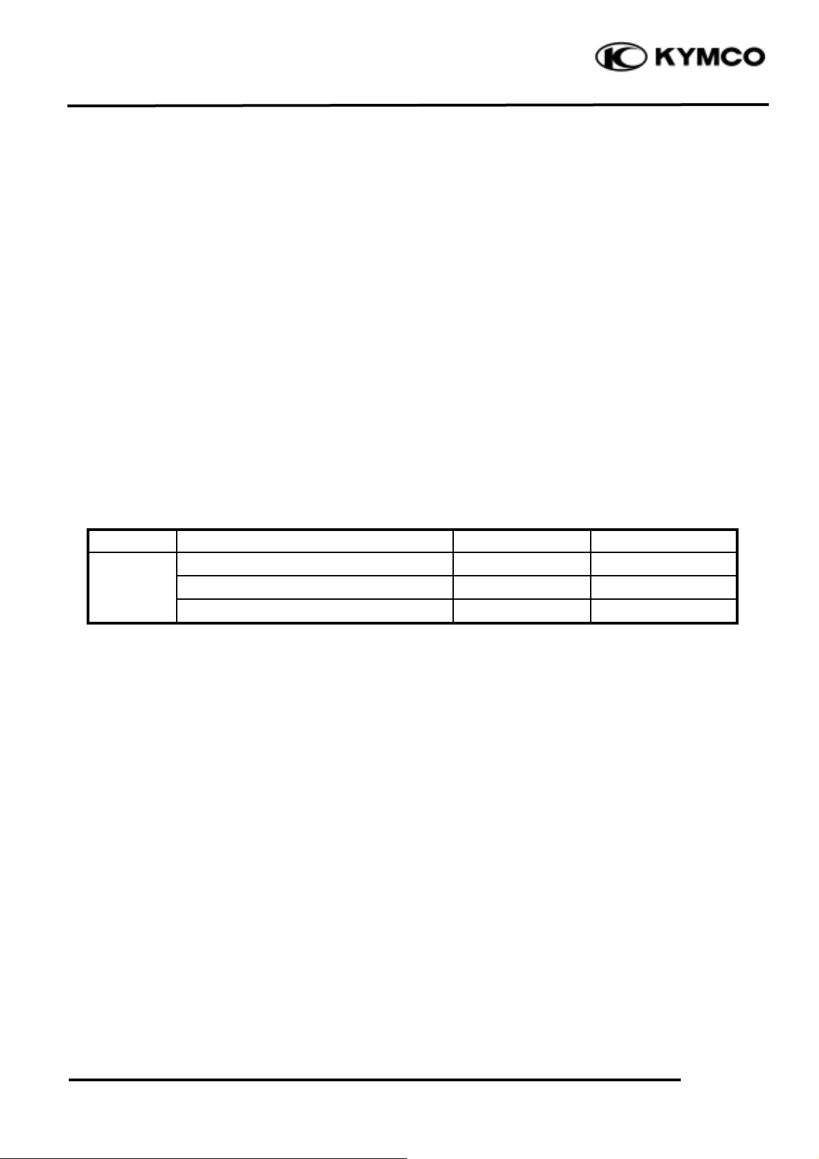
SPECIFICATIONS
Item
Standard (mm)
Service Limit (mm)
Connecting rod big end side clearance
0.15_ 0.35
0.6
Crankshaft
Connecting rod big end radial clearance
0._ 0.008
0.05
Runoutæ0.10
TORQUE VALUES
Crankcase bolt 7.8_ 10.8N-m
Cam chain tensioner slipper bolt 7.8_ 11.8N-m
SPECIAL TOOL
Gear remover
TROUBLESHOOTING
Excessive engine noise
• Excessive bearing play
• Excessive crankpin bearing play
• Worn piston pin and piston pin hole
 Loading...