

Page 1

5. ENGINE REMOVAL/INSTALLATION
5-0
Bet & Win 1 25 /1 50
5
__________________________________________________________________________________
__________________________________________________________________________________
__________________________________________________________________________________
__________________________________________________________________________________
__________________________________________________________________________________
ENGINE REMOVAL/INSTALLATION
__________________________________________________________________________________
SCHEMATIC DRAWING ---------------------------------------------- 5-1
SERVICE INFORMATION -------------------------------------------- 5-2
ENGINE REMOVAL --------------------------------------------------- 5-3
ENGINE INSTALLATION -------------------------------------------- 5-5
5
Page 2
5. ENGINE REMOVAL/INSTALLATION
5-1
Bet & Win 1 25 /1 50
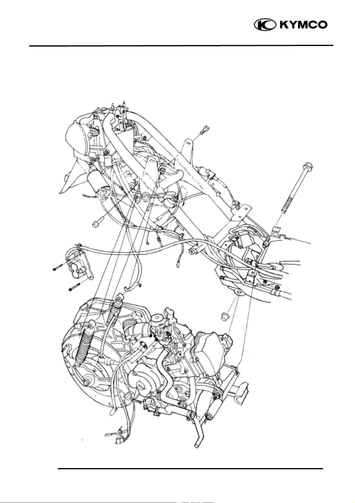
SCHEMATIC DRAWING
Page 3

5. ENGINE REMOVAL/INSTALLATION
5-2
Bet & Win 1 25 /1 50
SERVICE INFORMATION
GENERAL INSTRUCTIONS
• A floor jack or other adjustable support is required to support and maneuver the engine. Be
careful not to damage the motorcycle body, cables and wires during engine removal.
• Use shop towels to protect the motorcycle body during engine removal.
• Drain the coolant before removing the engine.
• After the engine is installed, fill the cooling system with coolant and be sure to bleed air from the
water jacket. Start the engine to check for coolant leaks.
• Before removing the engine, the rear brake caliper must be removed first. Be careful not to bend
or twist the brake fluid tube.
SPECIFICATIONS
Engine dry weight: 30kg
Engine oil capacity: at disassembly: 1.1 liter
Coolant capacity:
Total capacity : 1165cc
Radiator capacity : 825cc
Reserve tank capacity : 340cc
TORQUE VALUES
Engine mounting bolt 49N-m
Rear shock absorber upper mount bolt 39.2N-m
Page 4

5. ENGINE REMOVAL/INSTALLATION
5-3
Bet & Win 1 25 /1 50
ENGINE REMOVAL
Disconnect the battery negative cable.
Remove the frame body cover. (!2-3)
Disconnect the engine negative cable.
Disconnect all of the A.C. generator, auto
bystarter, spark plug, thermosensor wire
couplers and connectors.
Disconnect the engine fuel tube.
Drain the coolant. (!3-9)
Disconnect the water hose.
Disconnect the starter motor wire that goes to
the starter relay.
Disconnect the fuel tube and vacuum tube
that go to the carburetor from the fuel pump.
Disconnect the vacuum tube from the air cutoff valve (ACV).
Disconnect the throttle cable from the
carburetor.
Remove the brake fluid tube bolt of the rear
brake caliper.
Remove the rear brake caliper bolt and the
rear brake caliper.
Starter Relay
Wire Connectors
Rear Brake Caliper
ACV Vacuum Tube
Fuel Tube
Throttle Cable
Fuel Pump Vacuum Tube
Brake Fluid Tube
Rear Brake Caliper
Page 5

5. ENGINE REMOVAL/INSTALLATION
5-4
Bet & Win 1 25 /1 50
Remove the right/left rear shock absorber
upper mount bolts.
Remove the two engine mounting bolts and
pull out the engine with the engine hanger
backward.
ENGINE HANGER REMOVAL
Remove the engine hanger bolts to remove the
engine hanger.
Inspect the engine hanger bushings and
stopper rubber for wear or damage.
Engine Mounting Bolt
Bushings
Rear Shock Absorber Upper Mount Bolts
Engine Hanger Bolt
Stopper Rubber
Bolt
Engine Hanger
Page 6

5. ENGINE REMOVAL/INSTALLATION
5-5
Bet & Win 1 25 /1 50
ENGINE INSTALLATION
Install the engine in the reverse order of
removal.
Tighten the engine mounting bolts.
Torque: 49N-m
Tighten the rear shock absorber upper mount
bolts.
Torque: 39.2N-m
After installation, inspect and adjust the
following:
• Throttle grip free play (!3-3)
• Fill the rear brake reservoir with brake fluid
and bleed air from the rear brake.
• Fill the cooling system with coolant and
start the engine to bleed air from the
system.
Engine Mounting Bolt
Engine Hanger Bolt
Rear Shock Absorber Upper Mount Bolts
 Loading...