

KYMCO MX’er 125, LA30AA, MX’er 150, LA30AB Service Manual
PREFACE
This Service Manual describes the
technical features and servicing
procedures for the KYMCO MX’er
125/150.
Section 1 contains the precautions for
all operations stated in this manual.
Read them carefully before starting any
operation.
Section 2 is the removal/installation
procedures for the frame covers which
are subject to higher removal/installation
frequency during maintenance and
servicing operations.
Section 3 describes the inspection/
adjustment procedures, safety rules and
service information for each part, starting
from periodic maintenance.
Sections 4 through 17 give instructions
for disassembly, assembly and
inspection of engine, chassis frame and
electrical equipment.
Most sections start with an assembly or
system illustration and troubleshooting
for the section. The subsequent pages
give detailed procedures for the section.
KWANG YANG MOTOR CO., LTD.
OVERSEAS SALES DEPARTMENT
OVERSEAS SERVICE SECTION
TABLE OF CONTENTS
GENERAL INFORMATION 1
FRAME COVERS/EXHAUST M UFFLER 2
INSPECTION/ADJUSTMENT 3
LUBRICATION SYSTEM 4
FUEL SYSTEM 5
ENGINE REMOVAL/INSTALLATION 6
CYLINDER HEAD/VALVES 7
CYLINDER/PISTON 8
DRIVE AND DRIVEN PULLEYS
9
FINAL REDUCTION/TRANSMISSION
SYSTEM
10
CRANKCASE/CRANKSHAFT/
BALANCE SHAFT
11
FRONT WHEEL/FRONT BRAKE/
FRONT SUSPENSION/STEERING
SYSTEM
12
REAR WHEEL /SWING
ARM/HYDRAULIC BRAKE
13
BATTERY/CHARGING SYSTEM/A.C.
GENERATOR
14
IGNITION SYSTEM 15
STARTING SYSTEM 16
LIGHTS/SWITCHES 17
ONLY ATV ON ROAD AVAILABLE 18
The information and contents included
in this manual may be different from
the motorcycle in case specifications
are changed.
CHASSIS
ELECTRICAL
EQUIPMENT
ENGINE
1. GENERAL INFORMATION
1-0
MX’er SYSTEM
1
__________________________________________________________________________________
GENERAL INFORMATION
SERIAL NUMBER ------------------------------------------------------------- 1- 1
SPECIFICATIONS------------------------------------------------------------- 1- 2
SERVICE PRECAUTIONS -------------------------------------------------- 1- 4
TORQUE VALUES ------------------------------------------------------------ 1-12
SPECIAL TOOLS -------------------------------------------------------------- 1-14
LUBRICATION POINTS----------------------------------------------------- 1-15
CABLE & HARNESS ROUTING ------------------------------------------- 1-18
WIRING DIAGRAM ----------------------------------------------------------- 1-22
TROUBLESHOOTING ------------------------------------------------------- 1-23
1
1. GENERAL INFORMATION
1-1
MX’er SYSTEM
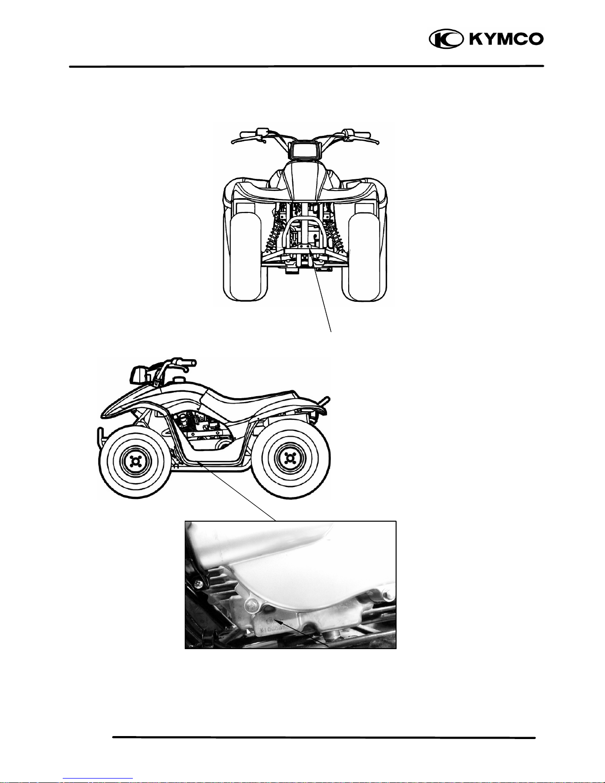
SERIAL NUMBER
Location of Engine Serial Number
Location of Frame Serial Number
1. GENERAL INFORMATION
1-2
MX’er SYSTEM
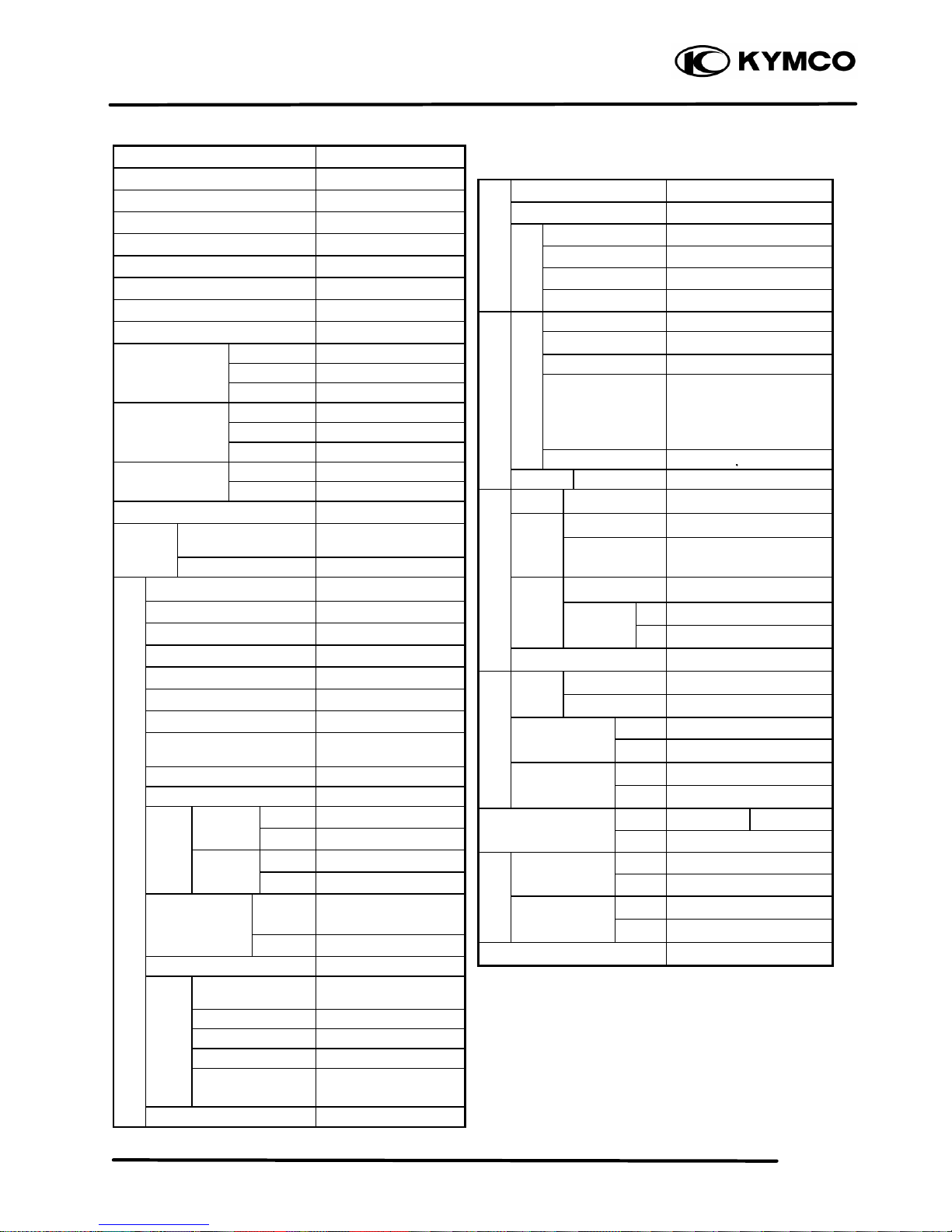
SPECIFICATIONS
Name & Model No. LA30AA, AB
Motorcycle Name & Type MX’er
Overall length (mm) 1600
Overall width (mm) 980
Overall height (mm) 990
Wheel base (mm) 1120
Engine type O.H.C.
Displacement (cc) 149.4
Fuel Used 92# nonleaded gasoline
Front wheel
74
Net weight (kg) Rear wheel
78
Total 152
Front wheel
80
Gross weight(kg) Rear wheel
82
Total 162
Front wheel
20*7-8
Rear wheel
22*10-8
Ground clearance (mm) 130
Perform-
Breaking distance
(m)(ANSI)
20.6 below
ance
Min. turning radius (m) 3
Starting system
Starting motor
Type Gasoline, 4-stroke
Cylinder arrangement Single cylinder
Combustion chamber type Semi -sphere
Valve arrangement O.H.C., chain drive
Bore x stroke (mm) 62 x 49.5
Compression ratio 9.7:1
Compression pressure
(kg/cm ²)
16.0
Max. output (ps/rpm) 11/7500
Max. torque (kg m/rpm) 1.1/5500
Intake
Open 5.5° BTDC
Port
(1mm)
Close 27.5 ° ABDC
timing
Exhaust
Open 36° BBDC
(1mm)
Close 4° ATDC
Valve
clearance
Intake 0.06
(cold) (mm) Exhaust 0.06
Idle speed (rpm) 1700rpm
Lubrication type
Forced pressure &
wet sump
Oil pump type Inner/outer rotor type
Oil filter type Full-flow filtration
Oil capacity 1.0 liter
Oil exchanging
capacity
0.9 liter
Cooling Type Forced air cooling
Air cleaner type & No
Sponge
Fuel capacity 8.1 liters
Type PD
Float lever 14.8mm
Venturi dia.(mm) φ25
Throttle type PISTON
Type CDI
Ignition timing 15°BTDC/1700rpm
Contact breaker Non-contact point type
Spark plug
NGK
CR8E
Spark plug gap 0.6 0.7mm
Battery Capacity 12V8AH
Clutch Type CVT
Type Helical gear
Operation
Automatic centrifugal
type
Type Chain drive
Reduction 1st 2.8-0.95
ratio
2nd
7.226
Counter gear ratio 26.902
Front Caster angle
Axle
Trail length
Tire pressure
Front
0.2
(kg/cm ²)
Rear 0.25
Turning Left 44°
angle
Right 44°
Brake system
Rear
Disk brake
Drum brake
type
Front Drum brake
Suspension
Front
Swing
type
Rear Swing arm
Shock absorber
Front Swing
type
Rear Swing arm
Frame type SP pipe
Tires
Engine
Lubrication
System
Fuel System
Carbureto
Electrical
Ignition System
Power Drive System
Transmis-
sion Gear
Reduction
Gear
Moving Device
Damping
Device
1. GENERAL INFORMATION
1-3
MX’er SYSTEM
SPECIFICATIONS
Name & Model No. LA25AB
Motorcycle Name & Type MX’er
Overall length (mm) 1685
Overall width (mm) 980
Overall height (mm) 990
Wheel base (mm) 1120
Engine type OHC
Displacement (cc) 124
Fuel Used 92# nonleaded gasoline
Front wheel
74
Net weight (kg) Rear wheel
78
Total 152
Front wheel
80
Gross weight(kg) Rear wheel
82
Total 162
Front wheel
20*7-8
Rear wheel
22*10-8
Ground clearance (mm) 130
Perform-
Breaking distance
(m)(ANSI)
20.6 below
ance
Min. turning radius (m) 2.5
Starting system Starting motor
Type Gasoline, 4-stroke
Cylinder arrangement Single cylinder
Combustion chamber type Semi -sphere
Valve arrangement O.H..C., chain drive
Bore x stroke (mm) 56.5 x 49.5
Compression ratio 9.2:1
Compression pressure
(kg/cm ²)
14.0
Max. output (ps/rpm) 9.8/7500
Max. torque (kg m/rpm) 0.98/5500
Intake
Open 5.5° BTDC
Port
(1mm)
Close 27.5 ° ABDC
Timin
Exhaust
Open
36° BBDC
(1mm)
Close 4° ATDC
Valve
clearance
Intake 0.06
(cold) (mm) Exhaust 0.06
Idle speed (rpm) 1700rpm
Lubrication type
Forced pressure &
wet sump
Oil pump type Inner/outer rotor type
Oil filter type Full-flow filtration
Oil capacity 1.0 liter
Oil exchanging
capacity
0.9 liter
Cooling Type Forced air cooling
Air cleaner type & No
Sponge
Fuel capacity 8.1 liters
Type PD
Piston dia. (mm) 14.8mm
Venturi dia.(mm) φ25
Throttle type PISTON
Type CDI
Ignition timing 15°BTDC/1700rpm
Contact breaker Non-contact point type
Spark plug
NGK
CR8E
Spark plug gap 0.6 0.7mm
Battery Capacity 12V8AH
Clutch Type CVT
Type Helical gear
Operation
Automatic centrifugal
type
Type Chain drive
Reduction 1st 2.8-0.95
ratio
2nd
7.226
Counter gear ratio 26.902
Front Caster angle
Axle
Trail length
Tire pressure
Front
0.2
(kg/cm ²)
Rear 0.25
Turning Left 44°
angle
Right 44°
Brake system
Rear
Disk brake
Drum brake
type
Front Drum brake
Suspension
Front
Swing
type
Rear Swing arm
Shock absorber
Front Swing
type
Rear Swing arm
Frame type SP pipe
Lubrication
System
Tires
Engine
Fuel System
Carbureto
Electrical
Ignition System
Power Drive System
Transmis-
sion Gear
Reduction
Gear
M
oving Device
Damping
Device
1. GENERAL INFORMATION
1-4
MX’er SYSTEM
SERVICE PRECAUTIONS
n Make sure to install new gaskets, O-rings,
circlips, cotter pins, etc. when reassembling.
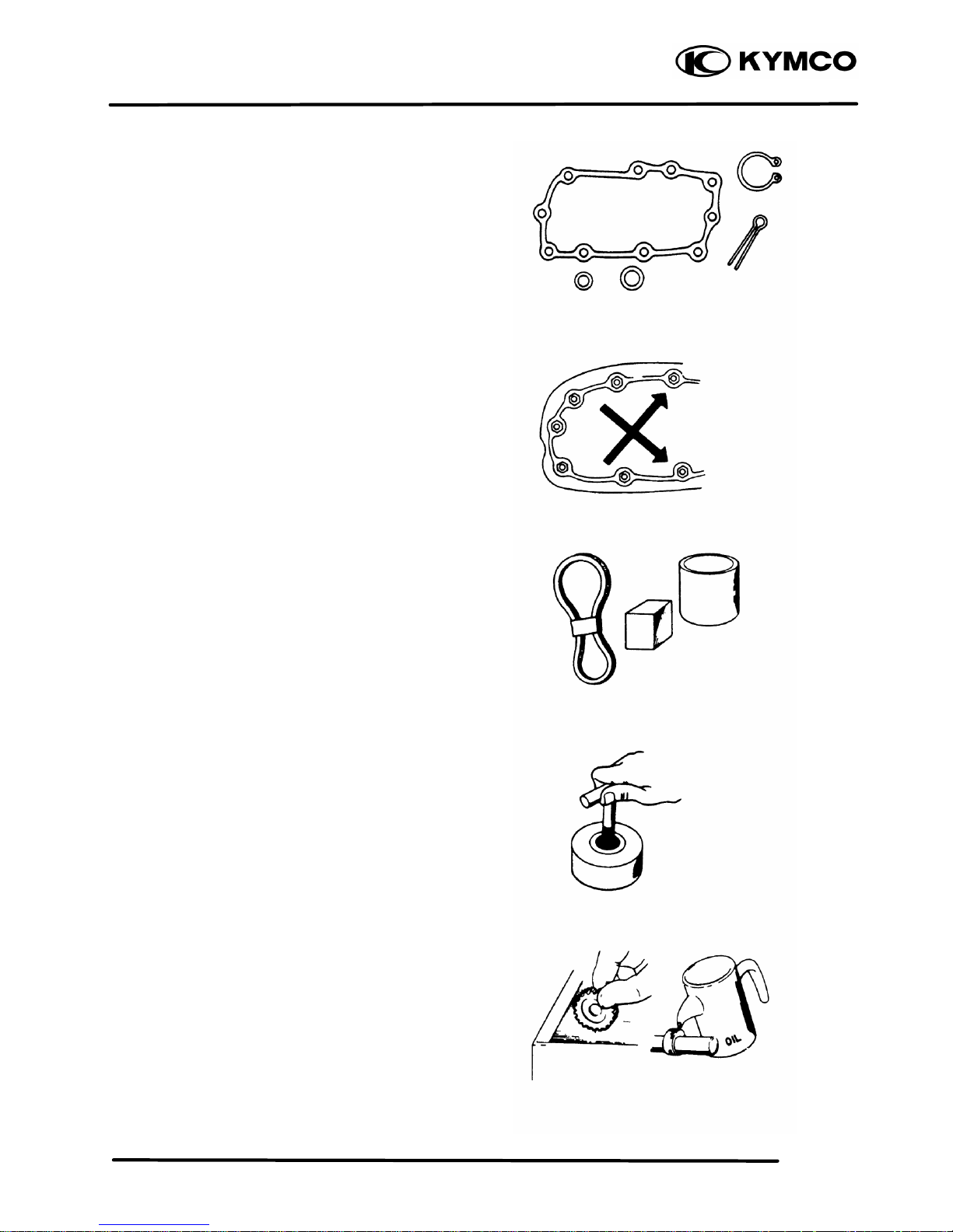
n When tightening bolts or nuts, begin with
larger-diameter to smaller ones at several
times, and tighten to the specified torque
diagonally.
n Use genuine parts and lubricants.
n When servicing the motorcycle, be sure to
use special tools for removal and installation.
n After disassembly, clean removed parts.
Lubricate sliding surfaces with engine oil
before reassembly.
1. GENERAL INFORMATION
1-5
MX’er SYSTEM
n Apply or add designated greases and
lubricants to the specified lubrication points.
n After reassembly, check all parts for proper
tightening and operation.
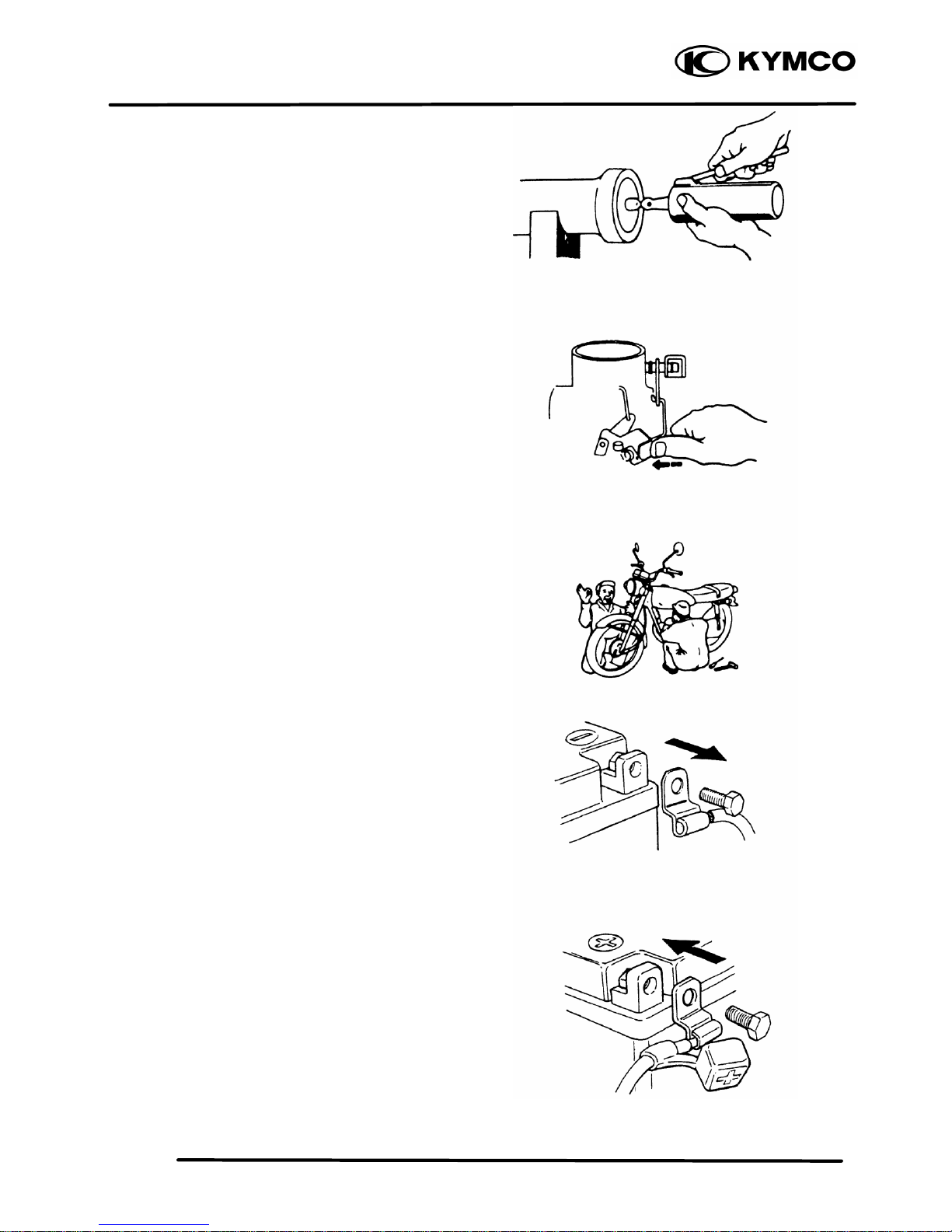
n When two persons work together, pay
attention to the mutual working safety.
n Disconnect the battery negative (-) terminal
before operation.
n When using a spanner or other tools, make
sure not to damage the motorcycle surface.
n After operation, check all connecting points,
fasteners, and lines for proper connection
and installation.
n When connecting the battery, the positive (+)
terminal must be connected first.
n After connection, apply grease to the battery
terminals.
n Terminal caps shall be installed securely.
1. GENERAL INFORMATION
1-6
MX’er SYSTEM
n If the fuse is burned out, find the cause and
repair it. Replace it with a new one
according to the specified capacity.
n After operation, terminal caps shall be
installed securely.
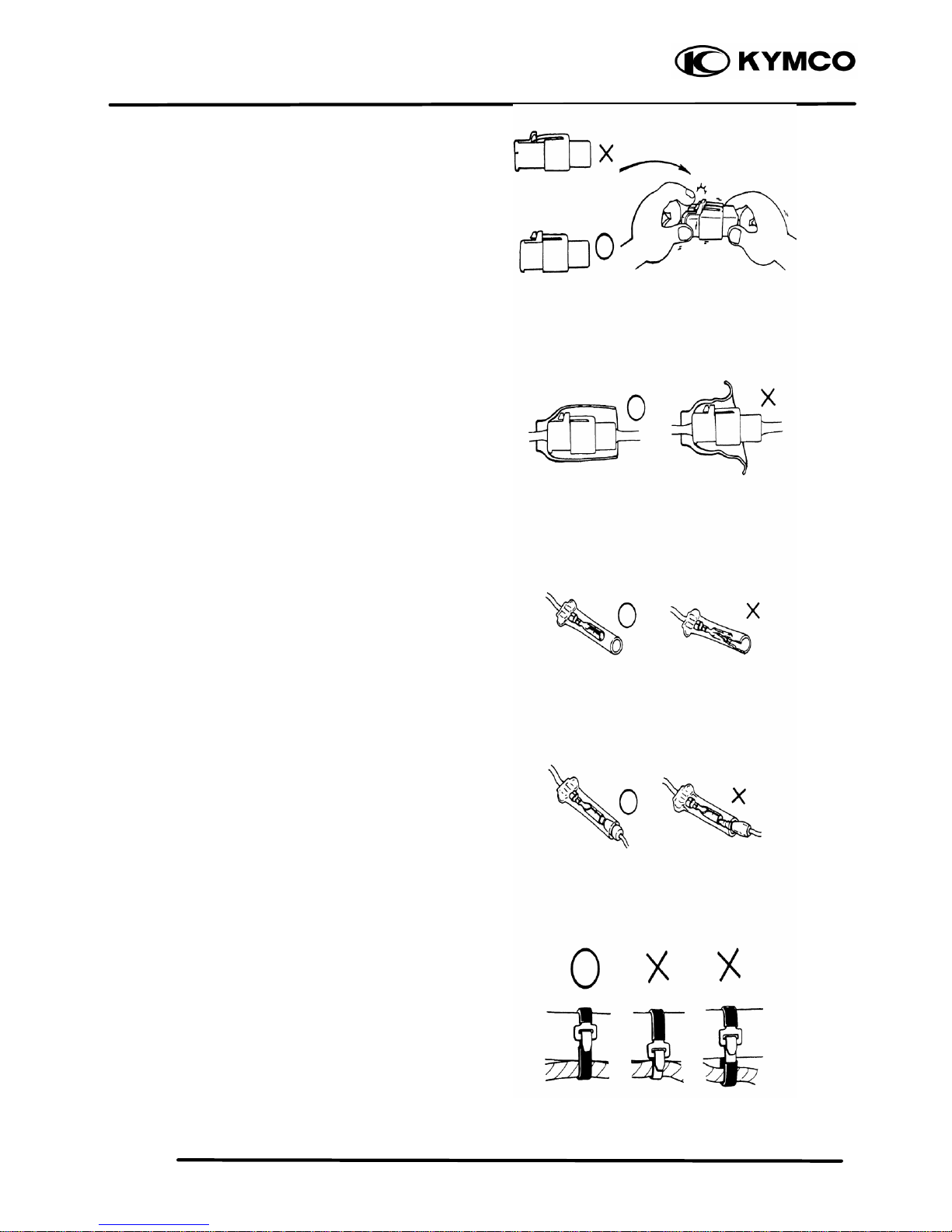
n When taking out the connector, the lock on
the connector shall be released before
operation.
n Hold the connector body when connecting
or disconnecting it.
n Do not pull the connector wire.
n Check if any connector terminal is bending,
protruding or loose.
Confirm
Capacity
1. GENERAL INFORMATION
1-7
MX’er SYSTEM
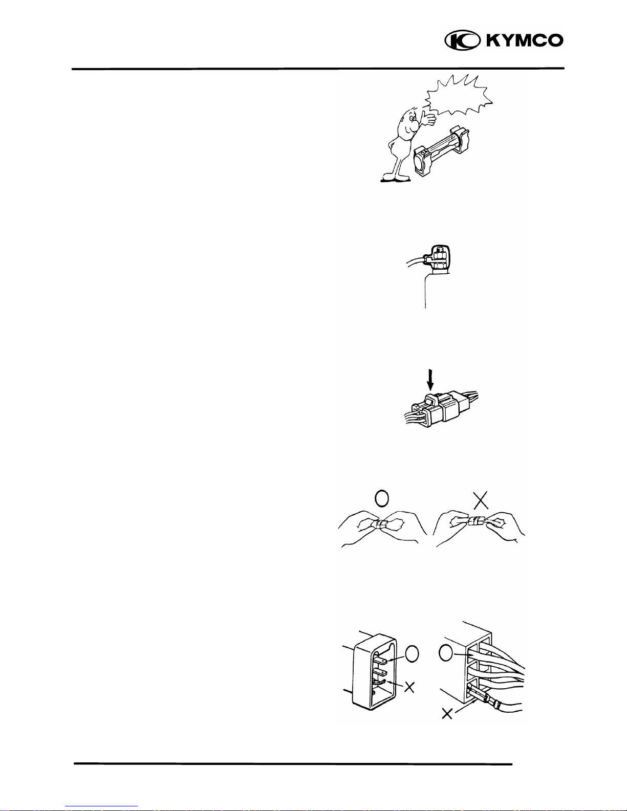
n The connector shall be inserted
completely.
n If the double connector has a lock, lock it
at the correct position.
n Check if there is any loose wire.
n Before connecting a terminal, check for
damaged terminal cover or loose negative
terminal.
n Check the double connector cover for
proper coverage and installation.
n Insert the terminal completely.
n Check the terminal cover for proper
coverage.
n Do not make the terminal cover opening face
up.
n Secure wire harnesses to the frame with their
respective wire bands at the designated
locations.
Tighten the bands so that only the insulated
surfaces contact the wire harnesses.
Snapping!
1. GENERAL INFORMATION
1-8
MX’er SYSTEM
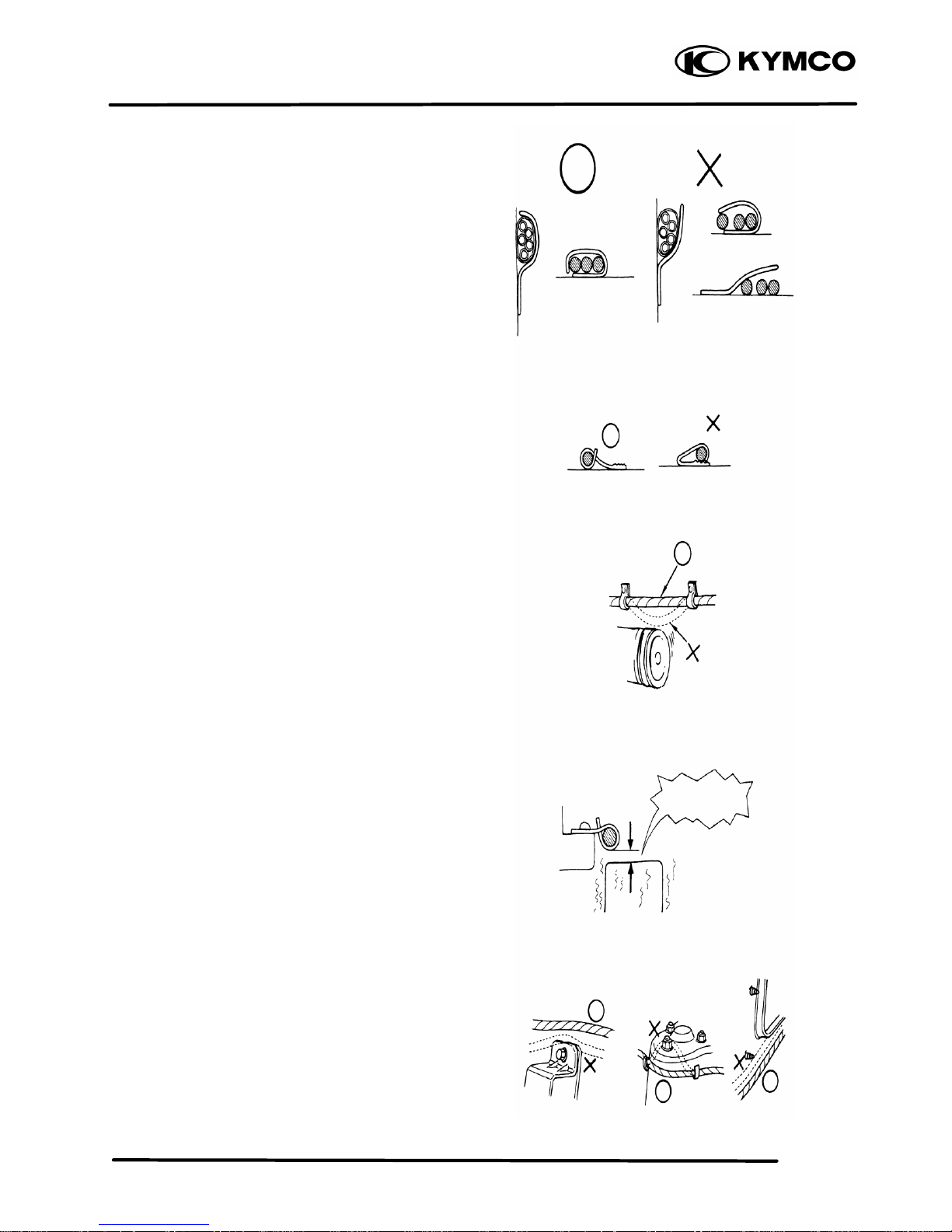
n After clamping, check each wire to make
sure it is secure.
n Do not squeeze wires against the weld or its
clamp.
n After clamping, check each harness to make
sure that it is not interfering with any moving
or sliding parts.
n When fixing the wire harnesses, do not make
it contact the parts which will generate high
heat.
n Route wire harnesses to avoid sharp edges
or corners. Avoid the projected ends of
bolts and screws.
n Route wire harnesses passing through the
side of bolts and screws. Avoid the
projected ends of bolts and screws.
No Contact !
1. GENERAL INFORMATION
1-9
MX’er SYSTEM
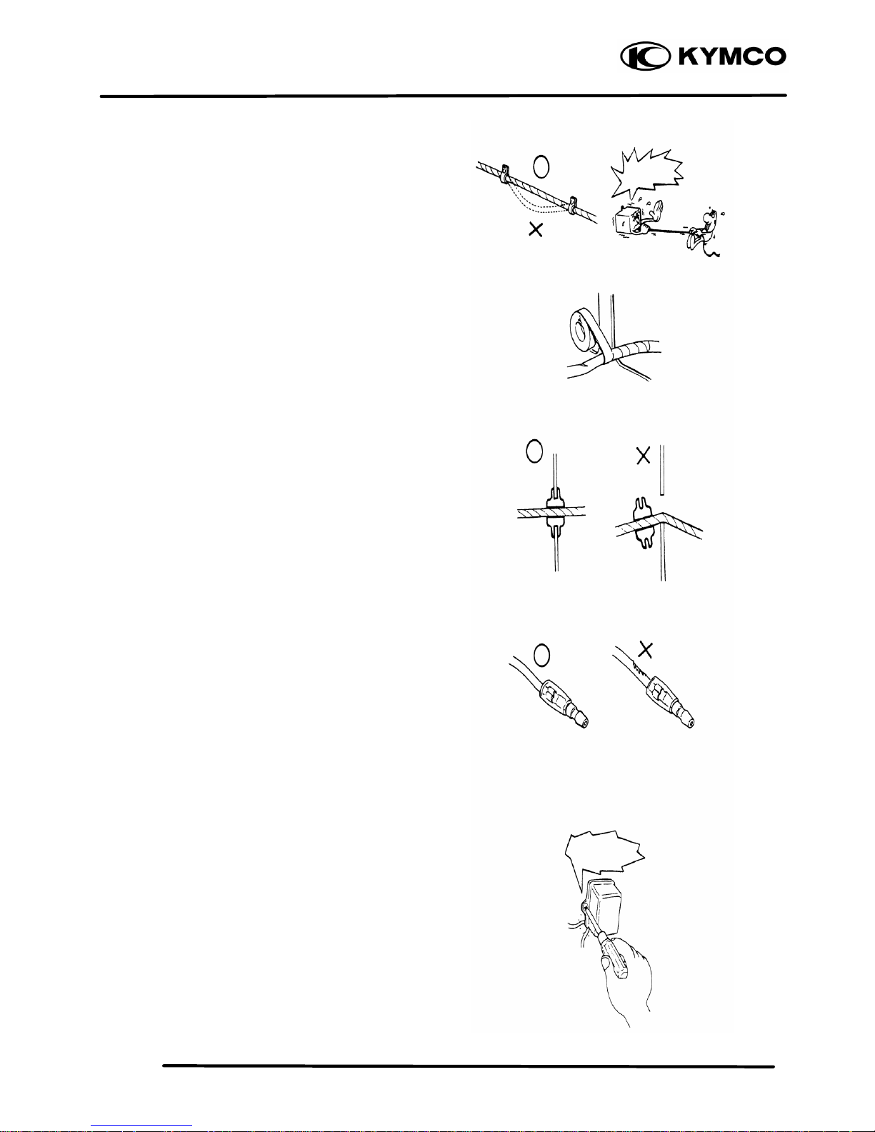
n Route harnesses so they are neither pulled
tight nor have excessive slack.
n Protect wires and harnesses with electrical
tape or tube if they contact a sharp edge or
corner.
n When rubber protecting cover is used to
protect the wire harnesses, it shall be
installed securely.
n Do not break the sheath of wire.
n If a wire or harness is with a broken sheath,
repair by wrapping it with protective tape or
replace it.
n When installing other parts, do not press or
squeeze the wires.
Do not pull
too tight!
Do not press
or squeeze
the wire.
1. GENERAL INFORMATION
1-10
MX’er SYSTEM
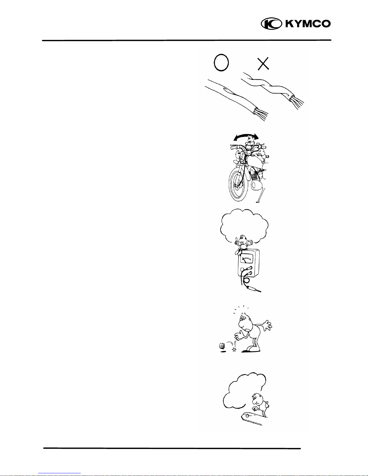
n After routing, check that the wire harnesses
are not twisted or kinked.
n Wire harnesses routed along with handlebar
should not be pulled tight, have excessive
slack or interfere with adjacent or
surrounding parts in all steering positions.
n When a testing device is used, make sure to
understand the operating methods thoroughly
and operate according to the operating
instructions.
n Be careful not to drop any parts.
n When rust is found on a terminal, remove the
rust with sand paper or equivalent before
connecting.
Do you understand
the instrument? Is
the instrument set
correctly?
Remove Rust !
1. GENERAL INFORMATION
1-11
MX’er SYSTEM
n Symbols:
The following symbols represent the
servicing methods and cautions included in
this service manual.
: Apply engine oil to the
specified points. (Use
designated engine oil for
lubrication.)
: Apply grease for lubrication.
: Transmission Gear Oil (90#)
: Use special tool.
: Caution
: Warning
Engine Oil
Grease
Gear Oil
Special
1. GENERAL INFORMATION
1-12
MX’er SYSTEM
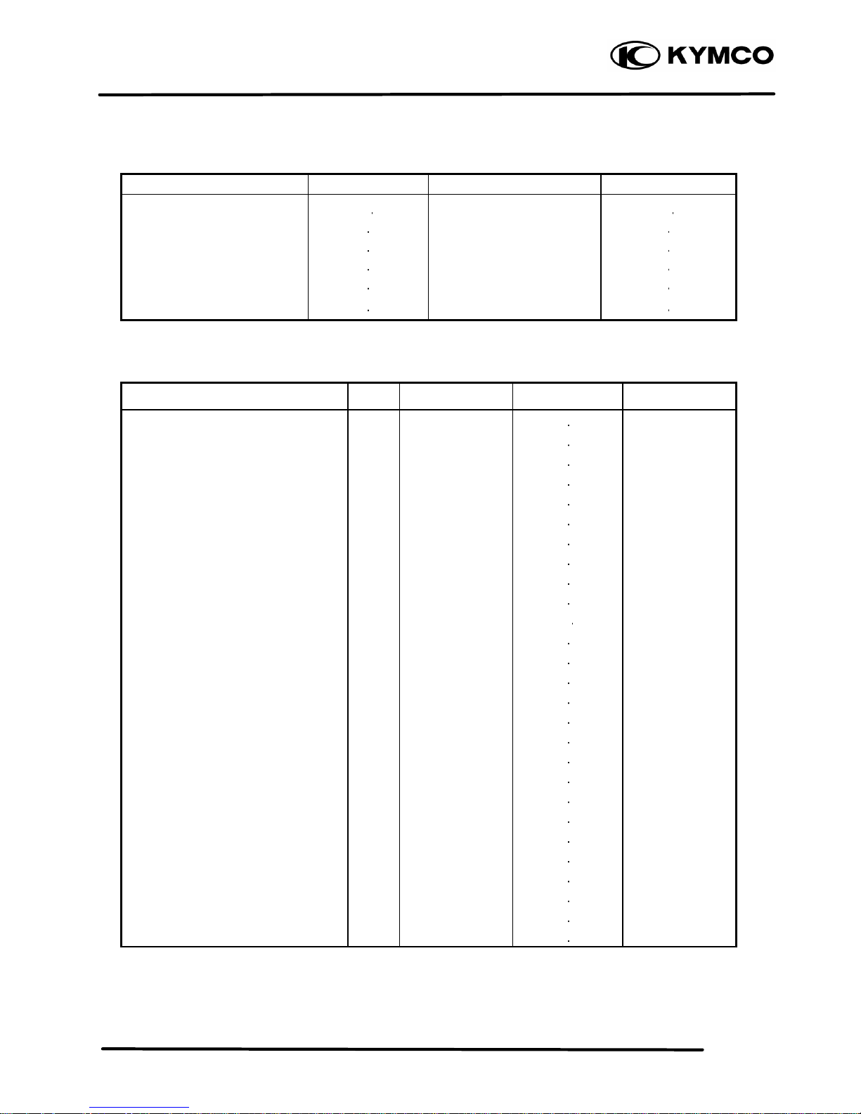
TORQUE VALUES
STANDARD TORQUE VALUES
Item Torque (kg
f-m) Item Torque (kg
f-m)
5mm bolt, nut
6mm bolt, nut
8mm bolt, nut
10mm bolt, nut
12mm bolt, nut
14mm bolt, nut
0.45 0.6
0.8 1.2
1.8 2.5
3.0 4.0
5.0 6.0
6.0 8.0
4mm screw
5mm screw
6mm screw, SH bolt
6mm flange bolt and nut
8mm flange bolt and nut
10mm flange bolt and nut
0.15 0.4
0.3 0.5
0.7 1.1
1.0 1.4
2.4 3.0
3.5 4.5
Torque specifications listed below are for important fasteners.
ENGINE
Item Q‘ty Thread dia.(mm) Torque (kgf -m)
Remarks
Stud bolt
Oil filter screen cap
Seat ball stopper bolt
Bearing hold
L cover
Stud bolt
Cam holder
Tappet ADJ nut
Pivot tensioner
Lifter tensioner
Lifter tensioner
MISTON oil drive bolt
Driver face
Clutch outer
Oneway clutch
Balancer shaft
ACG flywheel
Spark plug
Drain bolt mission
Drain plug
Clamper wre harness
Motor srart
Oil pump
Oil pump sprocket
Head CYL bolt
Drive plate nut
Startor
4
1
1
1
8
4
4
2
1
2
1
9
1
1
3
1
1
1
1
1
1
2
2
2
2
1
4
8
30
14
6
6
6
8
6
8
6
6
6
12
12
8
16
14
8
8
12
6
6
6
6
6
22
5
0.7 1.1
1.0 2.0
4.5 5.0
1.0 1.2
1.0 1.4
0.7 1.1
1.8 2.2
1.4 1.8
0.8 1.2
1.0 1.4
0.35 0.5
0.8 1.2
5.5 6.5
5.0 6.0
2.4 3.0
4.0 5.0
5.0 6.0
1.1 2.3
0.8 1.2
2.0 3.0
0.8 1.2
0.8 1.2
0.8 1.2
0.8 1.2
0.8 1.2
5.0 6.0
0.8 1.2
1. GENERAL INFORMATION
1-13
MX’er SYSTEM
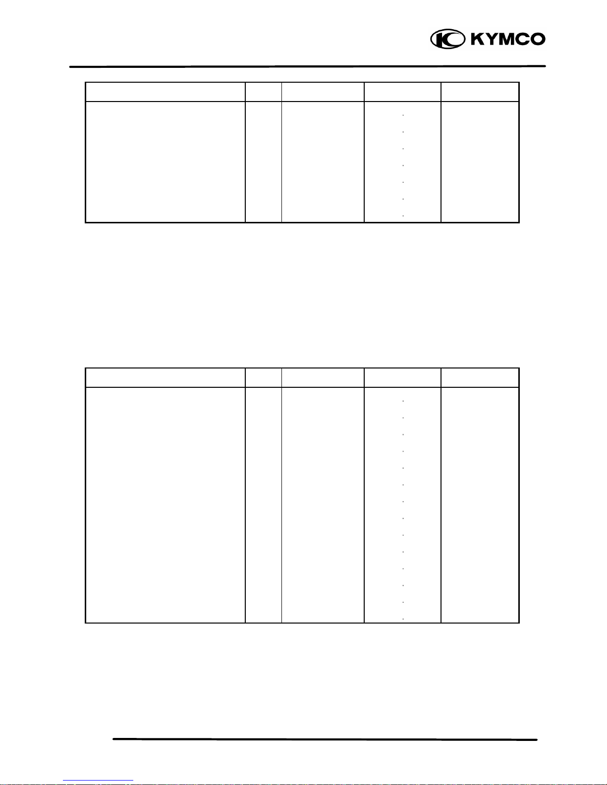
Item Q‘ty Thread dia.(mm) Torque (kgf-m)
Remarks
R cover
Head cover
Cap R cover
Guide star change handle
Sprocket drive plate
Carburetor
Check bolt oil
9
4
1
3
2
2
1
6
6
6
6
6
6
10
0.8 1.2
0.8 1.2
0.8 1.2
0.8 1.2
1.0 1.6
0.8 1.2
1.0 1.5
FRAME
Item Q‘ty Thread dia.(mm) Torque (kgf-m)
Remarks
Steering stem nut
Swing arm nut
Rear wheel nut
Front wheel nut
Rear shock absorber upper mount bolt
Front shock absorber upper mount bolt
Front shock absorber lower mount bolt
Rear fork axle
Rear hub nut
Rear wheel shaft nut
Rear engine bracket up bolt
Rear engine bracket bolt
Engine hanger bracket bolt
Exhaust muffler lock bolt
1
4
2
2
1
2
2
1
4
2
1
1
1
2
14
10
14
14
10
10
10
14
12
32
10
10
10
8
6.0 8.0
4.0 5.0
6.0 8.0
6.0 8.0
3.5 4.5
3.5 4.5
3.5 4.5
6.0 8.0
6.0 8.0
11.0 13.0
3.5 4.5
3.5 4.5
3.5 4.5
3.2 3.8
1. GENERAL INFORMATION
1-14
MX’er SYSTEM
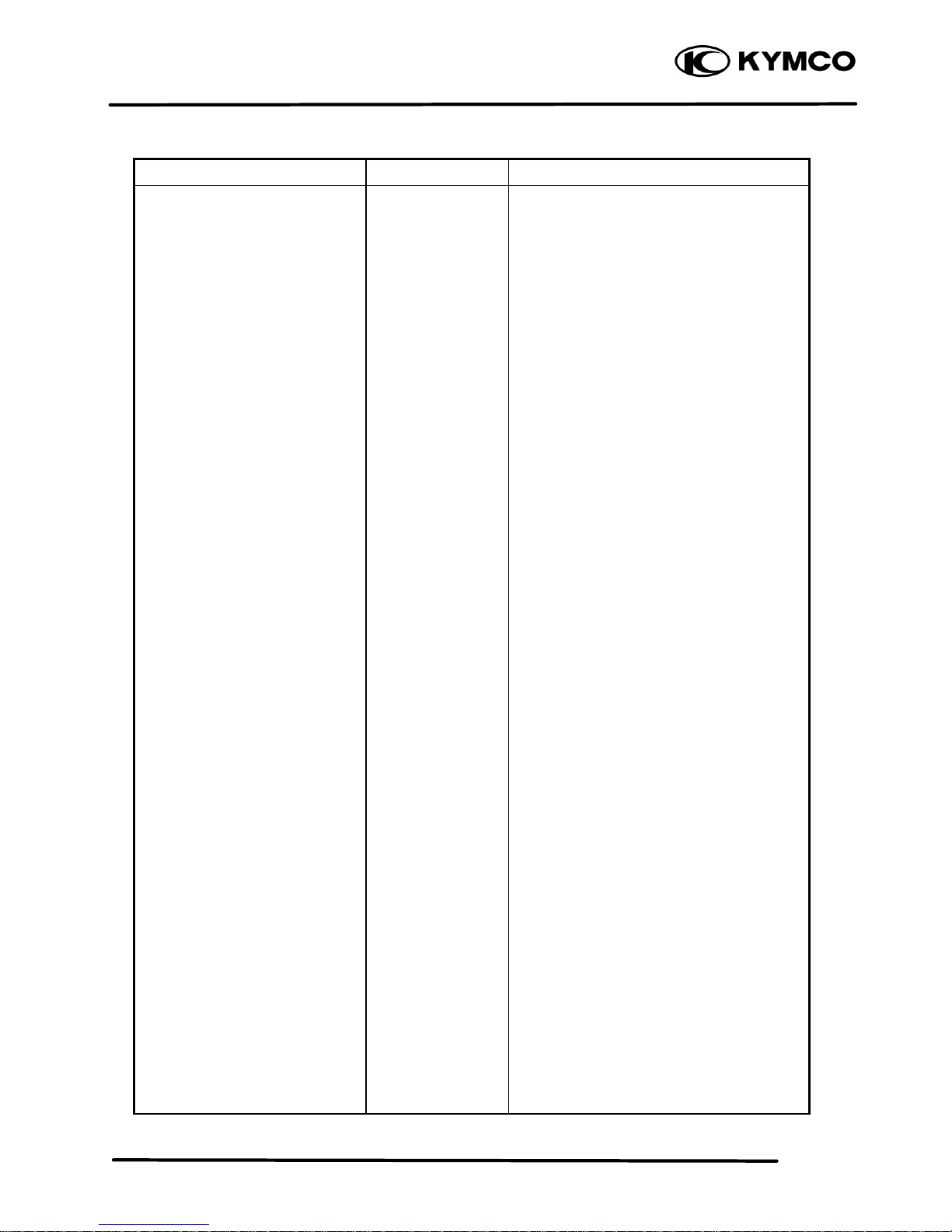
SPECIAL TOOLS
Tool Name Tool No. Remarks Ref. Page
Flywheel puller E003
Lock nut wrench E009
Valve adjuster E012
Valve spring compressor E040
Oil seal and bearing install E014
Universal holder E017
Flywheel holder E021
Clutch spring compressor E027
Bearing puller E008
Bearing puller E018
Bearing puller E020
Bearing puller E031
Nut wrench F010
Float level gauge
1. GENERAL INFORMATION
1-15
MX’er SYSTEM
LUBRICATION POINTS
ENGINE
Lubrication Points Lubricant
Valve guide/valve stem movable part
Cam lobes
Valve rocker arm friction surface
Cam chain
Cylinder lock bolt and nut
Piston surroundings and piston ring grooves
Piston pin surroundings
Cylinder inside wall
Connecting rod/piston pin hole
Connecting rod big end
Crankshaft right side oil seal
Crankshaft one -way clutch movable part
Oil pump drive chain
Balance gear
A.C. generator
Starter one-way clutch
Bearing movable part
O-ring face
Oil seal lip
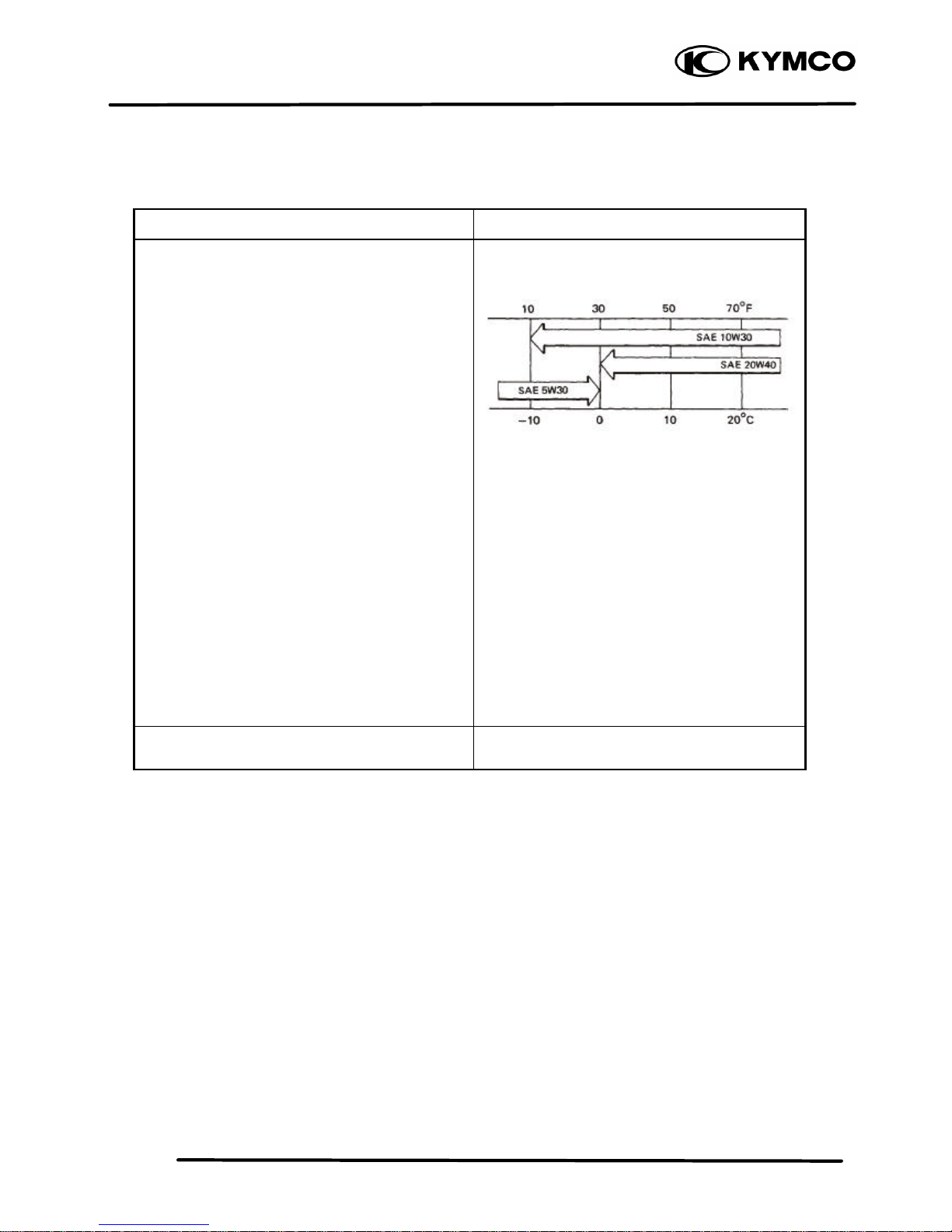
•Genuine KYMCO Engine Oil (SAE15W-40)
•API SG Engine Oil
Transmission gear and movable parts Gear oil: SAE90#
1. GENERAL INFORMATION
1-16
MX’er SYSTEM
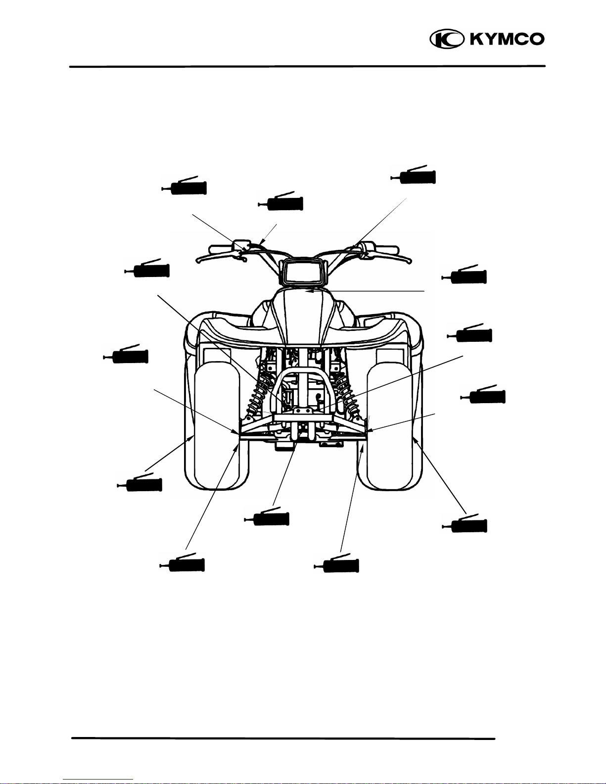
FRAME
The following is the lubrication points for the frame.
Use general purpose grease for parts not listed.
Apply clean engine oil or grease to cables and movable parts not specified. This will avoid abnormal
noise and rise the durability of the motorcycle.
Steering knuckle/Thrust
Cover/Bush/Collar
Steering Column Upper
Rear Brake Cable
Front Brake
camshaft/Oil
Seal/O-ring
Throttle Cable
Front Brake Cable
Steer
ing Column Lower
Front Wheel
Oil Seal
Front Arm Bush
Front Brake
camshaft/Oil
Seal/O-ring
Front Wheel
Oil Seal
Steering knuckle/Thrust
Cover/Bush/Collar
Front Arm Bush
1. GENERAL INFORMATION
1-17
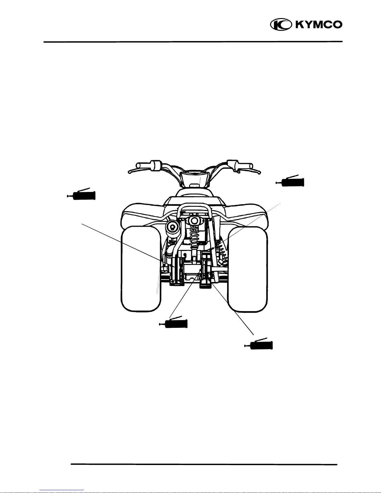
MX’er SYSTEM
Sprocket hub/Rear
Axle Hub Collar/Oil
Seal/Bearing
Rear Brake Cam/ Axle
Hub Collar/Oil
Seal/Bearing
Driven Sprocket
Swing arm Thrust
Cover
1. GENERAL INFORMATION
1-18
MX’er SYSTEM
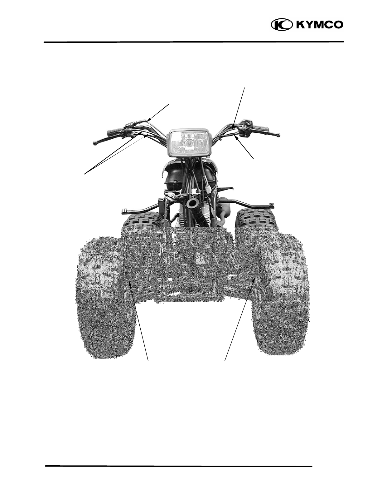
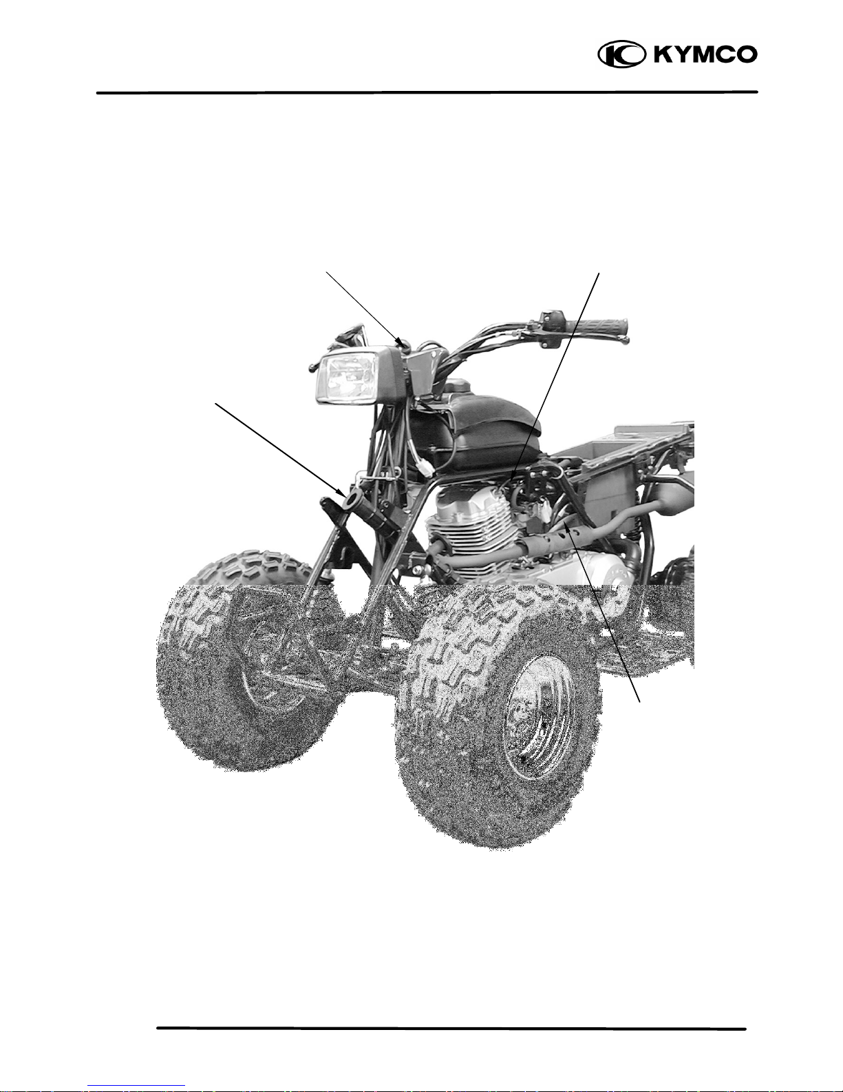
CABLE & HARNESS ROUTING
Throttle Cable
Rear Brake Cable
Right
Front Brake
Cable
Handlebar Switch Lead
Front Brake
Cable
Left
Front Brake
Cable
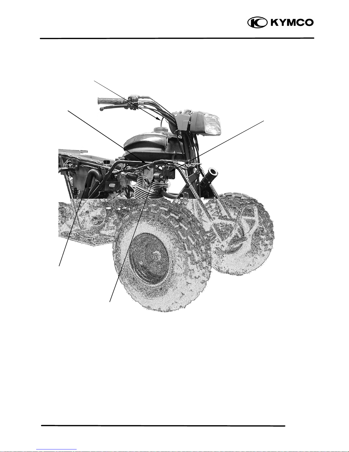
1. GENERAL INFORMATION
1-19
MX’er SYSTEM
Main Switch
Inlet Hose
Breather Hose
(Crankcase)
Breather Hose (CYL
Head Cover)
1. GENERAL INFORMATION
1-20
MX’er SYSTEM
Wire Harness
Fuse
Breather Ho
se
Rectifier/Regulator
Ignition Coil
Outlet Hose
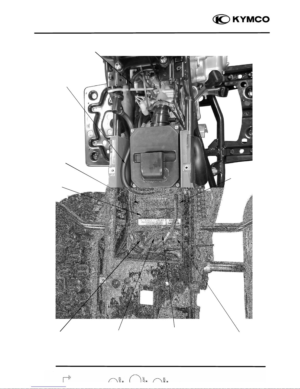
1. GENERAL INFORMATION
1-21
MX’er SYSTEM
Battery Negative
Cable
Change Gear Control
A.C.G Wire
Connector
Battery
Starter Relay
Positive Cable
CDI Unit
Fuse
Breather Hose (CYL
Head Cover)

1. GENERAL INFORMATION
1-22
MX’er SYSTEM
WIRING DIAGRAM
1. GENERAL INFORMATION
1-23
MX’er SYSTEM
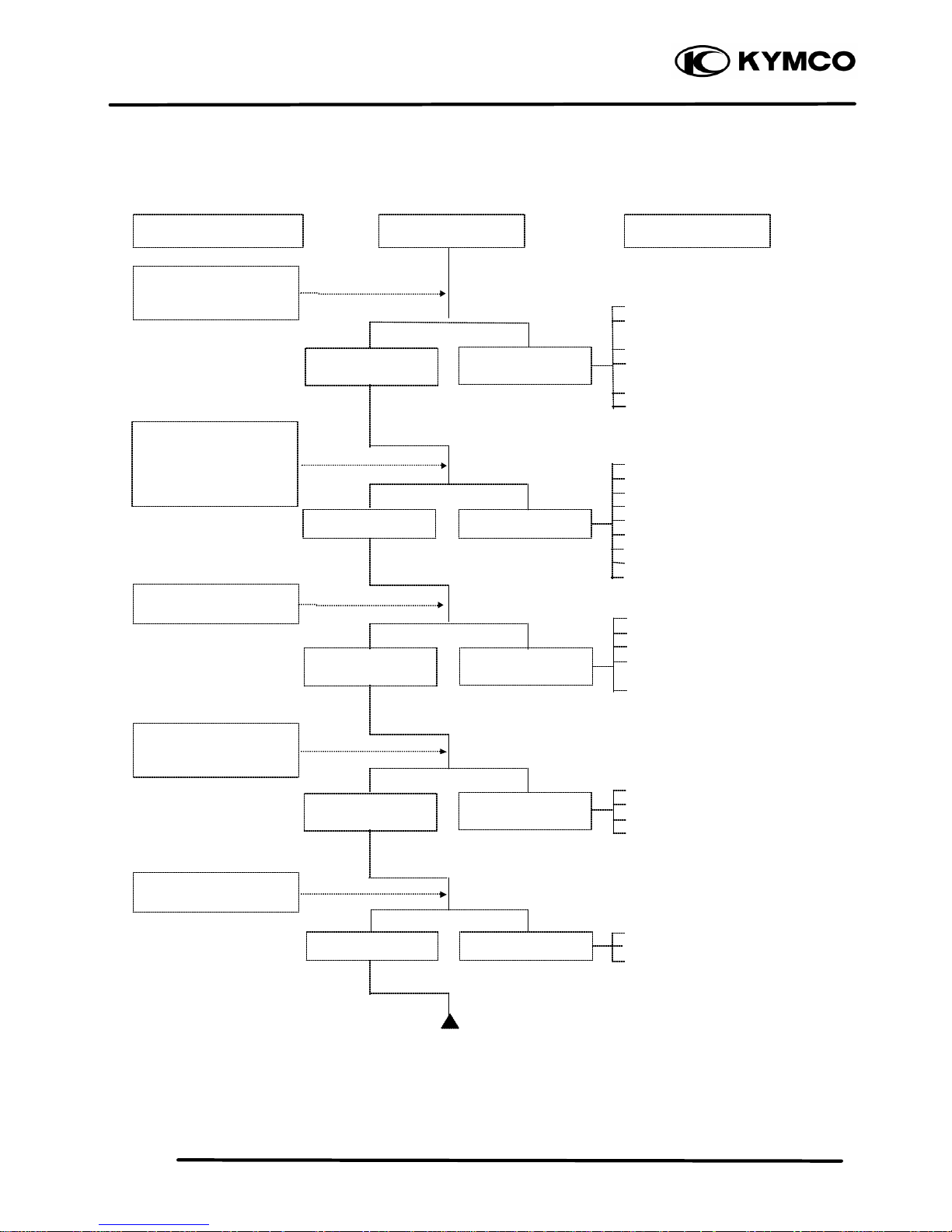
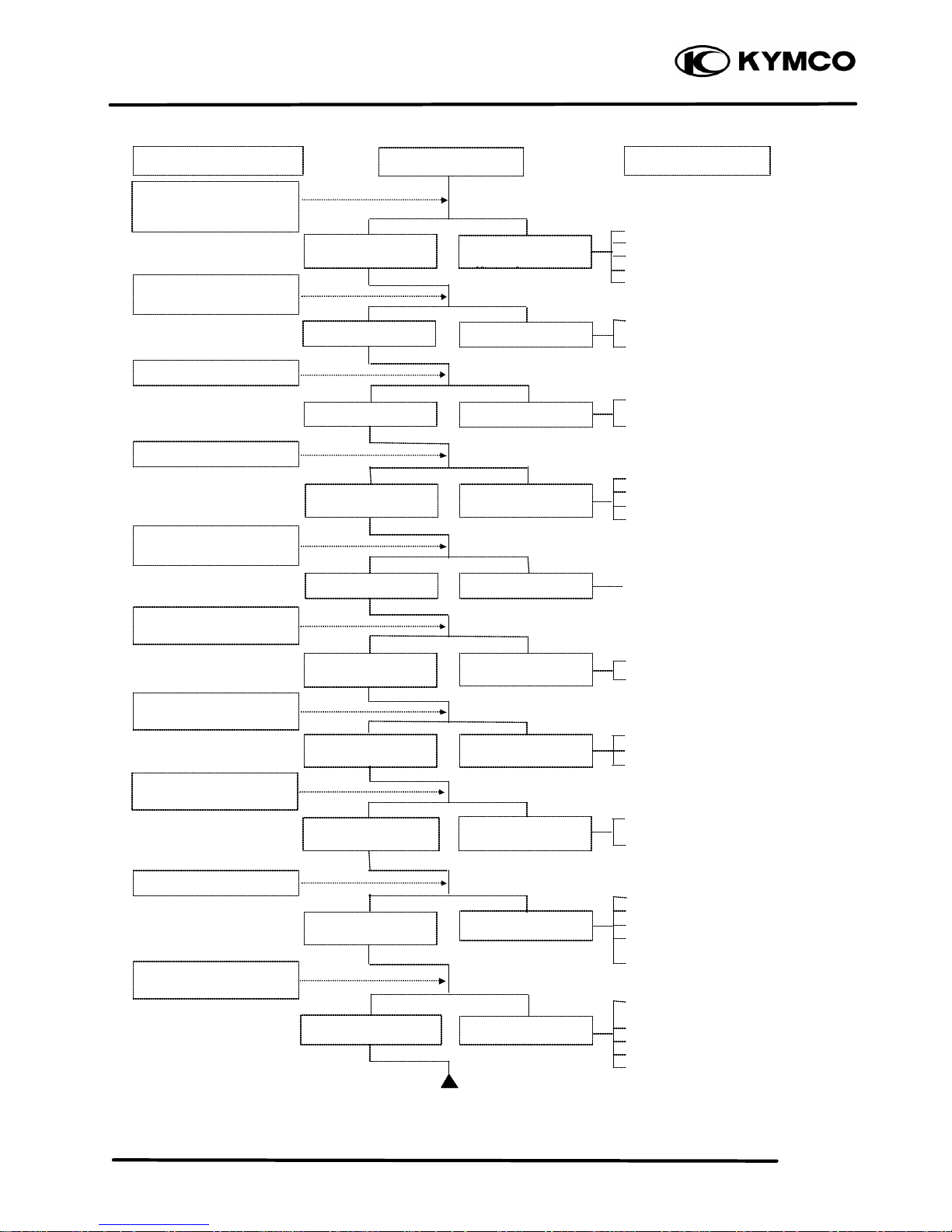
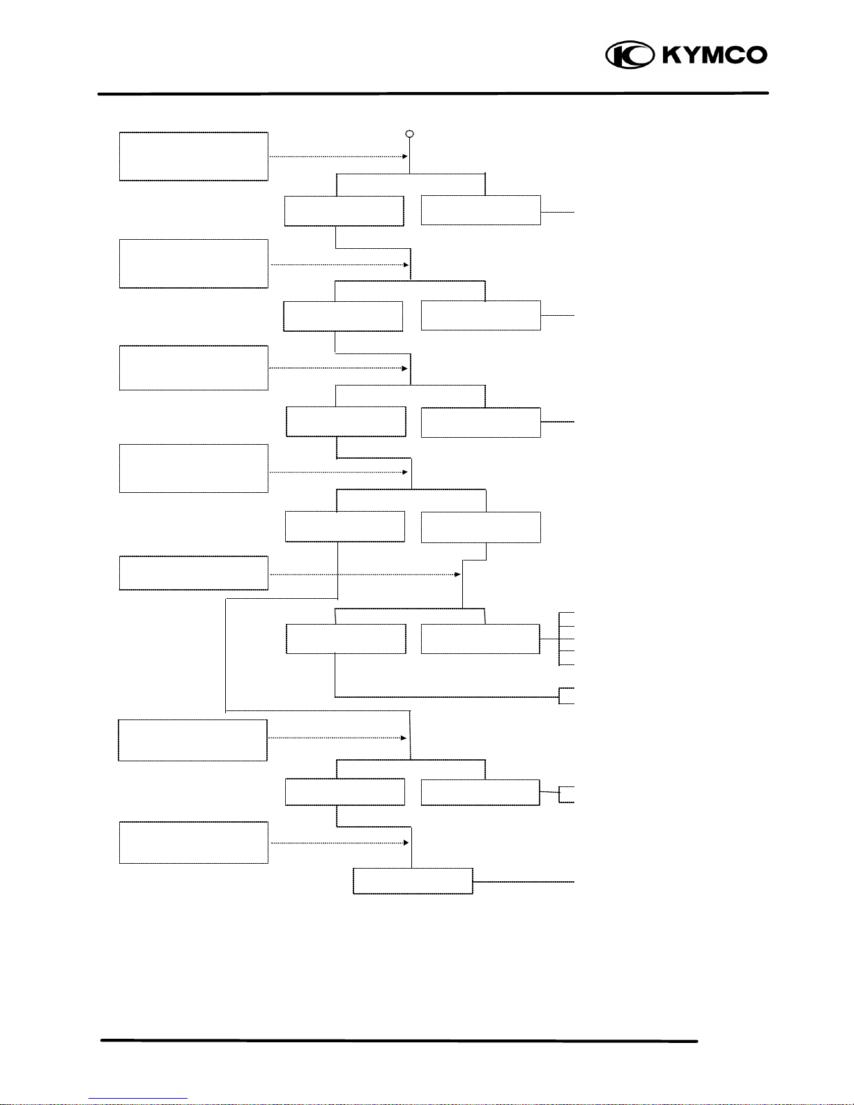
TROUBLESHOOTING
ENGINE WILL NOT START OR IS HARD TO START
Empty fuel tank
Clogged fuel line between fuel
tank and carburetor
Clogged float oil passage
Clogged fuel tank cap breather
hole
Clogged fuel filter
Clogged fuel valve passage
Faulty spark plug
Fouled spark plug
Faulty CDI unit
Faulty change gear control unit
Faulty pulser coil
Broken or shorted ignition coil
Broken or shorted exciter coil
Faulty ignition switch
Weak or dead battery
Faulty starter clutch
Valve clearance too small
Valve stuck open
Worn cylinder, piston and piston
rings
Leaking cylinder head gasket
Air leaking through intake pipe
Leaking intake manifold
Incorrect ignition timing
Incorrectly adjusted air*/ screw
Flooded carburetor
Clogged air cleaner
Throttle valve excessively open
Check if fuel reaches
carburetor by loosening
drain screw
Remove spark plug and
install it into spa rk plug
cap to test spark by
connecting it to engine
ground
Inspection/Adjustment Probable Cause
Spark jumps
Normal
compression
Engine does not
fire
Weak or no spark
Low or no
compression
Engine fires but
does not start
Test cylinder
compression
Start engine by
follow-ing normal
starting procedure
Remove spark plug and
inspect again
Symptom
Fuel reaches
carburetor
Fuel does not
reach carburetor
Wet spark plug
Dry spark plug
1. GENERAL INFORMATION
1-24
MX’er SYSTEM
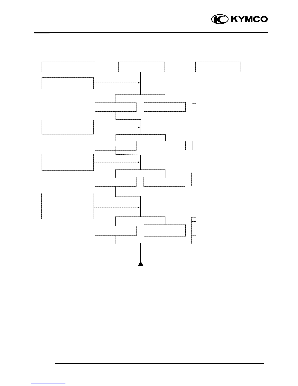
ENGINE LACKS POWER
Clogged ai r cleaner
Restricted fuel flow
Clogged fuel tank cap breather hole
Clogged exhaust muffler
Carburetor fuel level too low
Faulty CDI unit
Faulty pulser coil
Improper valve clearance
adjustment
Excessively worn valve seat
(protruded valve stem)
Improper valve and seat contact
Worn cylinder and piston rings
Leaking cylinder head gasket
Improper valve timing
Clean and unclog
Fouled spark plug
Incorrect heat range pl ug
Oil level too high
Oil level too low
Oil not changed
Clogged oil line
Faulty oil pump
Worn cylinder and piston rings
Mixture too lean
Poor quality fuel
Excessive carbon build-up in
combustion chamber
Ignition timing too early
Excessive carbon build-up in
combustion chamber
Poor quality fuel
Clutch slipping
Mixture too lean
Ignition timing too early
Start engine and accelerate
lightly for observation
Inspection/Adjustment
Symptom
Probable Cause
Engine speed
increases
Correct timing
Engine speed does
not increase
Incorrect timing
Check ignition timing
(using a timing light)
Test cylinder compression
Check carburetor for
clogging
Rapidly accelerate or run
at high speed
Remove spark plug and
inspect
Check if engine overheats
Check valve clearance
Correct
Incorrect
Normal
compression
Abnormal
compression
Remove oil dipstick and
check oil level and condition
Remov
e cylinder head oil
pipe bolt and inspect
Engine overheats
Engine does not
overheats
Plug not fouled or
discolored
Plug fouled or
discolored
Correct and not
contaminated
Incorrect or
contaminated
Valve train lubricated
properly
Valve train not
lubricated properly
Engine does not knock
Engine knocks
Not clogged
Clogged
1. GENERAL INFORMATION
1-25
MX’er SYSTEM
POOR PERFORMANCE (ESPECIALLY AT IDLE AND LOW SPEEDS)
Faulty CDI unit
Faulty pulser coil
Mixture too rich (turn screw out)
Mixture too lean (turn screw in)
Deteriorated O-ring
Carburetor not securely
tightened
Damaged insulator rubber
Faulty or fouled spark plug
Faulty CDI unit
Faulty A.C. generator
Faulty ignition coil
Broken or shorted spark plug
wire
Faulty ignition switch
Remove spark plug and
install it into spark plug
cap to test spark by
connecting it to engine
ground
Inspection/Adjustment Symptom Probable Cause
Check ignition timing
Check carburetor
gasket for air leaks
Check carburetor air
screw adjustment
Correct timing Incorrect timing
Correctly adjusted
No air leak Air leaks
Good spark
Weak or inter
-
mittent spark
Incorrectly
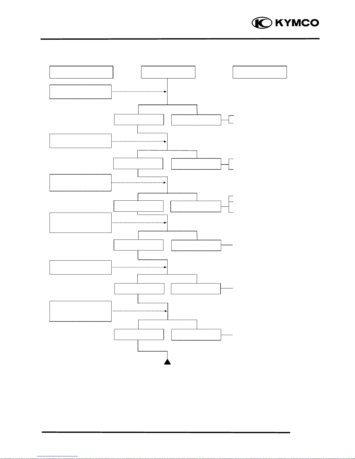
1. GENERAL INFORMATION
1-26
MX’er SYSTEM
POOR PERFORMANCE (AT HIGH SPEED)
Faulty CDI unit
Faulty pulser coil
Improperly adjusted valve
clearance
Worn valve seat
Empty fuel tank
Clogged fuel tube or filter
Clogged Fuel tank cap breather
hole
Clean and unclog
Cam timing gear aligning marks
not aligned
Faulty spring
POOR CHARGING (BATTERY OVER DISCHARGING OR OVERCHARGING)
Inspection/Adjustment Symptom Probable Cause
Check ignition timing
Check carburetor jets
for clogging
Check fuel pump for
fuel supply
Correct timing Incorrect timing
Check valve spring
tension
Check valve clearance
Fuel flows freely Fuel flow restricted
Correct
Incorrect
Not clogged Clogged
Correctly adjusted
Incorrectly adjusted
Not weakened Weak spring
Check valve timing
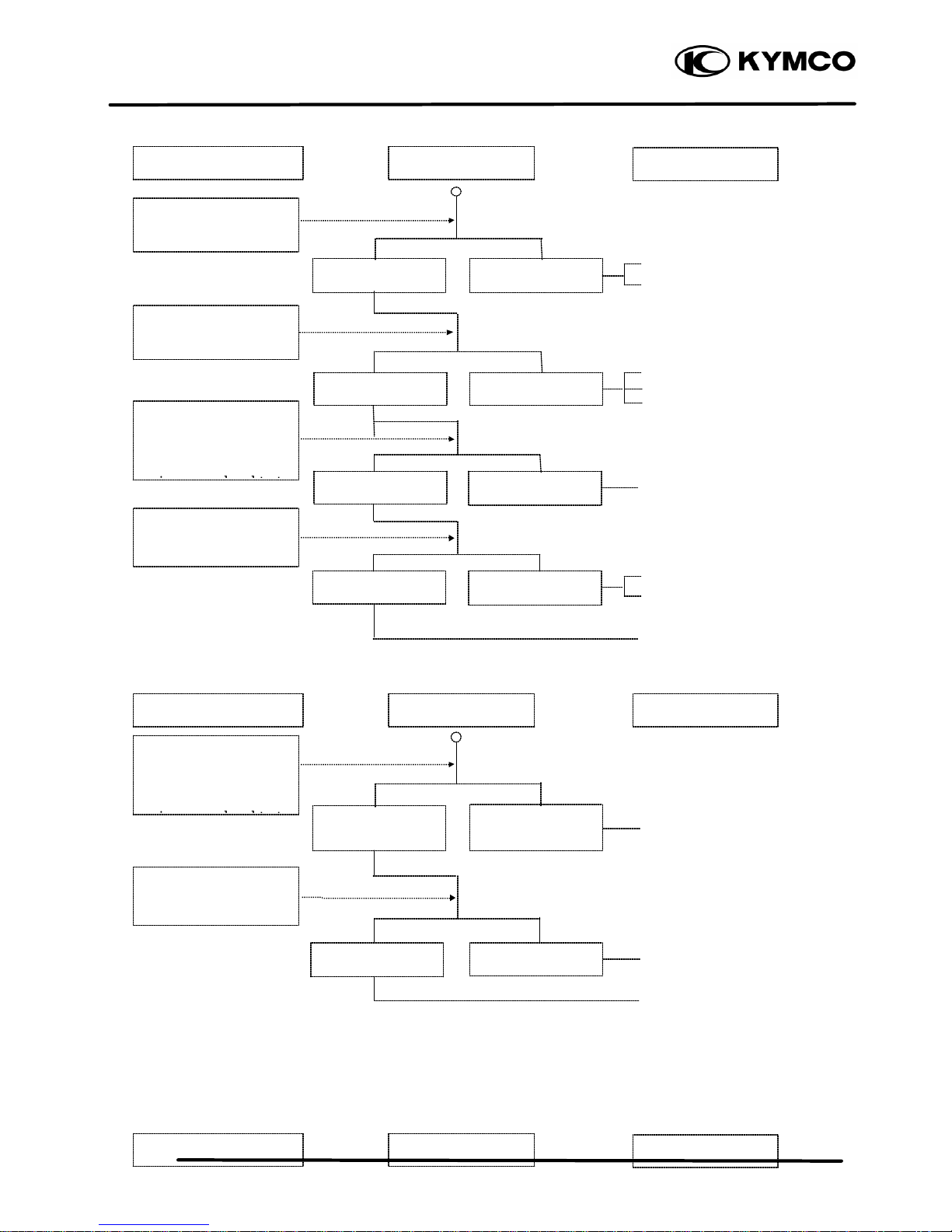
1. GENERAL INFORMATION
1-27
MX’er SYSTEM
Undercharging
Dead battery
Faulty battery
Faulty A.C. generator coil
Broken yellow wire
Shorted pink and yellow wires
Broken red wire
Faulty regulator/rectifier
Poorly connected coupler
Faulty A.C. generator
Overcharging
Broken green wire
Poorly connected coupler
Faulty regulator/rectifier
NO SPARK AT SPARK PLUG
Start engine and test
limit voltage of battery
terminals
Inspection/Adjustment
Connect battery (+)
wire to
regulator/rectifier
coupler red wire and
battery (
-
) wire to
Symptom
Inspection/Adjustment
Probable Cause
Inspection/Adjustment
Symptom
Symptom
Probable Cause
Probable Cause
Normal voltage
Battery has voltage
with ignition switch
“ON”
Normal
Voltage does not
increase
Battery has no
voltage with ignition
switch
“ON”
Resistance too high
Normal voltage
No voltage
Measure resistance
between AC generator
coil terminals
Normal Abnormal
Check
regulator/rectifier
coupler for loose
Normal
Abnormal
Connect battery (+)
wire to
regulator/rectifier
coupler green wire and
battery (
-
) wire to
Check
regulator/rectifier
coupler for loose
1. GENERAL INFORMATION
1-28
MX’er SYSTEM
Faulty spark plug
Loose spark plug cap
Poorly connected coupler
Faulty ignition switch
Weak battery
Faulty pulser coil
Faulty ignition coil
Faulty charging system
Broken wire harness
Poorly connected coupler
Faulty CDI unit
Faulty change gear control
unit
Faulty ignition coil
Replace with a new
spark plug and inspect
again
Check CDI unit coupler
for looseness
Normal
Abnormal
Normal
Abnormal
Normal
Abnormal
Abnormal
Measure resistance
between terminals of
CDI unit coupler
Check related parts
Check ignition coil with
a CDI unit tester
Weak or no spark
Not loose
Good spark
Loose
Good
Good
Check spark plug cap
and high-tension wire
for looseness
Check CDI unit with a
CDI unit tester
 Loading...