

Page 1
MP120A
Page 2
CAUTION
RISK OF ELECTRIC SHOCK
DO NOT OPEN
The lightning flash with the arrowhead symbol, within an equilateral
triangle is intended to alert the user to the presence of uninsulated
"dangerous voltage" within the product's enclosure that may be of
sufficient magnitude to constitute a risk of electric shock to persons.
CAUTION: TO REDUCE THE RISK OF ELECTRIC SHOCK,
REFER SERVICING TO QUALIFIED SERVICE PERSONNEL.
DO NOT REMOVE THE COVER.
NO USER SERVICEABLE PARTS INSIDE.
The exclamation point within an equilateral triangle is intended
to alert the user to the presence of important operating and
maintenance (servicing) instructions in the literature
accompanying the product.
IMPORTANT SAFETY & INSTALLATION INSTRUCTIONS
INSTRUCTIONS PERTAINING TO THE RISK OF FIRE ELECTRIC SHOCK , OR INJURY TO PERSONS
WARNING: When using electric products, basic precautions should
always be followed, including the following:
1. Read all the Safety and Installation Instructions and Explanation
of Graphic Symbols before using the product.
2. This product must be grounded. If it should malfunction or
break down, grounding provides a path of least resistance for
electric current to reduce the risk of electric shock. This product
is equipped with a power supply cord having an equipmentgrounding conductor and a grounding plug. The plug must be
plugged into an appropriate outlet which is properly installed and
grounded in accordance with all local codes and ordinances.
DANGER: Improper connection of the equipment-grounding
conductor can result in a risk of electric shock. Do not modify the
adaptor which defeats the function of the equipment-grounding
conductor. If you are in doubt as to whether the product is properly
3. Do not use this product near water – for example, near a bathtub,
washbowl, kitchen sink, in a wet basement, or near a swimming
pool, or the like.
4. This product should only be used with a stand or cart that is
recommended by the manufacturer.
5.
speakers or headphones, may be capable of producing sound
levels that could cause permanent hearing loss. Do not operate
for a long period of time at a high volume level or a level that is
uncomfortable. If you experience any hearing loss or ringing in
the ears, you should consult an audiologist.
6. This product should be located so that its location or position
does not interfere with its proper ventilation.
7. The product should be located away from heat sources such as
radiators, heat registers, or other products that produce heat.
8. The product should be connected to a power supply only of the
type described in the operating instructions or as marked on the
product.
9. This product may be equipped with a polarized line plug (one
blade wider than the other). This is a safety feature. If you are
unable to insert the plug into the outlet, contact an electrician to
replace your obsolete outlet. Do not defeat the safety purpose of
the plug.
10. The power supply cord of the product should be unplugged
from the outlet when left unused for a long period of time. When
unplugging the power supply cord, do not pull on the cord, but
grasp it by the plug.
11. Care should be taken so that objects do not fall and liquids are
not spilled into the enclosure through openings.
12.
when:
A. The power supply, power cord or plug have been damaged;
B. Objects have fallen, or liquid has been spilled into the
product;
C. The product has been exposed to rain;
D. The product does not appear to be operating normally or
exhibits a marked change in performance;
E. The product has been dropped, or the enclosure damaged.
13. Do not attempt to service the product beyond that described in
the user maintenance instructions. All other servicing should be
14. WARNING: Do not place objects on the product’s power supply
cord, or place the product in a position where anyone could trip
over, walk on, or roll anything over cords of any type. Do not
allow the product to rest on or be installed over cords of any type.
hazard and/or personal injury.
RADIO AND TELEVISION INTERFERENCE
WARNING:
approved by Young Chang could void your authority to operate the
instrument.
IMPORTANT: When connecting this product to accessories and/or
other equipment use only high quality shielded cables.
NOTE: This instrument has been tested and found to comply with the
limits for a Class B digital device, pursuant to Part 15 of the FCC Rules.
These limits are designed to provide reasonable protection against
harmful interference in a residential installation. This instrument
generates, uses, and can radiate radio frequency energy and, if not
installed and used in accordance with the instructions, may cause
harmful interference to radio communications. However, there is no
guarantee that interference will not occur in a particular installation. If
this instrument does cause harmful interference to radio or television
reception, which can be determined by turning the instrument off and
on, the user is encouraged to try to correct the interference by one or
more of the following measures:
• Reorient or relocate the receiving antenna.
SAVE THESE INSTRUCTIONS
ii
• Increase the separation between the instrument and the receiver.
• Connect the instrument into an outlet on a circuit other than the
one to which the receiver is connected.
• If necessary consult your dealer or an experienced radio/television
technician for additional suggestions.
The normal function of the product may be disturbed by strong
electromagnetic interference. If so, simply reset the product to resume
normal operation by following the instructions in the manual. If normal
function does not resume, please use the product in another location.
NOTICE
This apparatus does not exceed the Class B limits for radio noise
emissions from digital apparatus set out in the Radio Interference
Regulations of the Canadian Department of Communications.
AVIS
Le present appareil numerique n’emet pas de bruits radioelectriques
depassant les limites applicables aux appareils numeriques de la
class B prescrites dans le Reglement sur le brouillage radioelectrique
edicte par le ministere des Communications du Canada.
Page 3
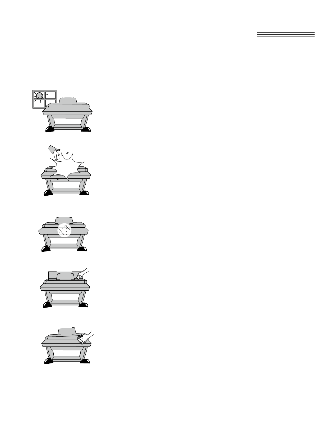
Installation Site and Precautions
● Avoid direct sunlight.
● Avoid exposing this product to rapid changes in temperature.
● Avoid excessive dusty or dirty location.
● Do not place near any heat sources such as radiators, heat
registers, stoves, or other apparatus (including ampliers)
that produce heat.
● Do not place objects, such as vases, glasses, and coffee cups,
on the product.
● Do not let paper, metallic, or other objects into the instrument.
● Do not open inside personally.
● When repair is needed, please contact the Kurzweil A/S center
● Clean only with a soft, dry cloth. Do not use paint thinners,
solvents, cleaning uids, or chemical-impregnated wiping cloths.
Page 4

Contents
Chapter 1 Primary Features .............................................................................
Chapter 2 Assembly Instructions ....................................................................
Chapter 3 Left Panel ..........................................................................................
Chapter 4 Voice & Piano ..................................................................................
Chapter 5 Layer Mode ......................................................................................
Chapter 6 Split Mode ........................................................................................
Chapter 7 Function Button ..............................................................................
Chapter 8 Record/Duo Mode ..........................................................................
Chapter 9 Demo/EDU mode ..........................................................................
Chapter 10 Metronome(Rhythm)/Transpose Mode .......................................
5
6−10
11
12
13
14
15−18
19
20
21
Chapter 11 Pedal ...............................................................................................
Using Bluetooth ............................................................................
Chapter 12 MIDI .................................................................................................
Chapter 13 Connectors ....................................................................................
1. Headphone
2. Audio In/Out
3. Smart Recording
Chapter 14 Percussion Placement ................................................................
Chapter 15 Demo Song List ............................................................................
Chapter 16 Sonatine List .................................................................................
Chapter 17 GM Sound List .............................................................................
Chapter 18 Specications ...............................................................................
........................................................................................
......................................................................................
...............................................................................
22
22
23
25
25
25
25
26
27
28
29
30
Page 5

Chapter1
Primary Features
Congratulations on your purchase of a MP120A.
You are certain to enjoy many hours exploring the variety of features as well
as 30 kinds of the beautiful preset voices.
1. Primary features
● 88-NOTE, Fully-Weight, Graded Hammer-Action, 3-Point Sensor Keyboard
● 30 Voices + 128 GM Voices
● 20 Rhythm patterns
● 5 x 7 Dot Matrix LCD Display
● Duo Mode
● Layer/Split/Traspose Mode
● 256 Voice Polyphony
● Favorite Button for piano voice
● Performance Recorder
● Compatible with MIDI & Computer les
● 50 Built-in Demo Songs
● Built-in educational songs (Beyer, Czerny, Sonatine, Hanon, Burgmuller)
● Built-in Sustain Pedal, Sostenuto Pedal and Soft Pedal
(Half Pedal, String/Damper Resonance)
● 10 levels of keyboard sensitivity
● Stereo Audio Input and Output
● Two Headphone Inputs
● USB MIDI In and Out ports, Audio connection
● Smart Audio In and Out ports (4-pole)
● Auto Power Off
● Bluetooth
5
Page 6
Chapter2
Assembly Instructions
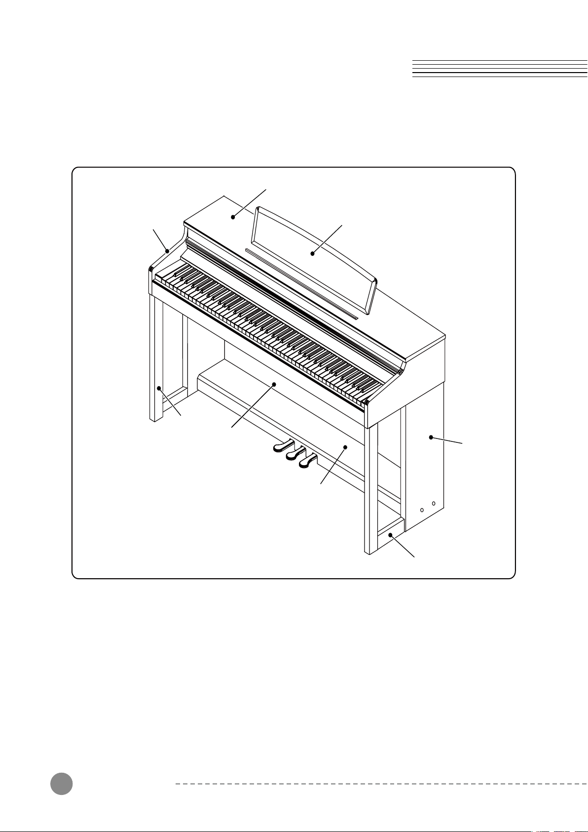
Instrument Description
Upper Cover
Arms
Music stand
Legs
Back Panel
Side Panel
Pedal Box
Assembly Instructions
6
Feet
Page 7
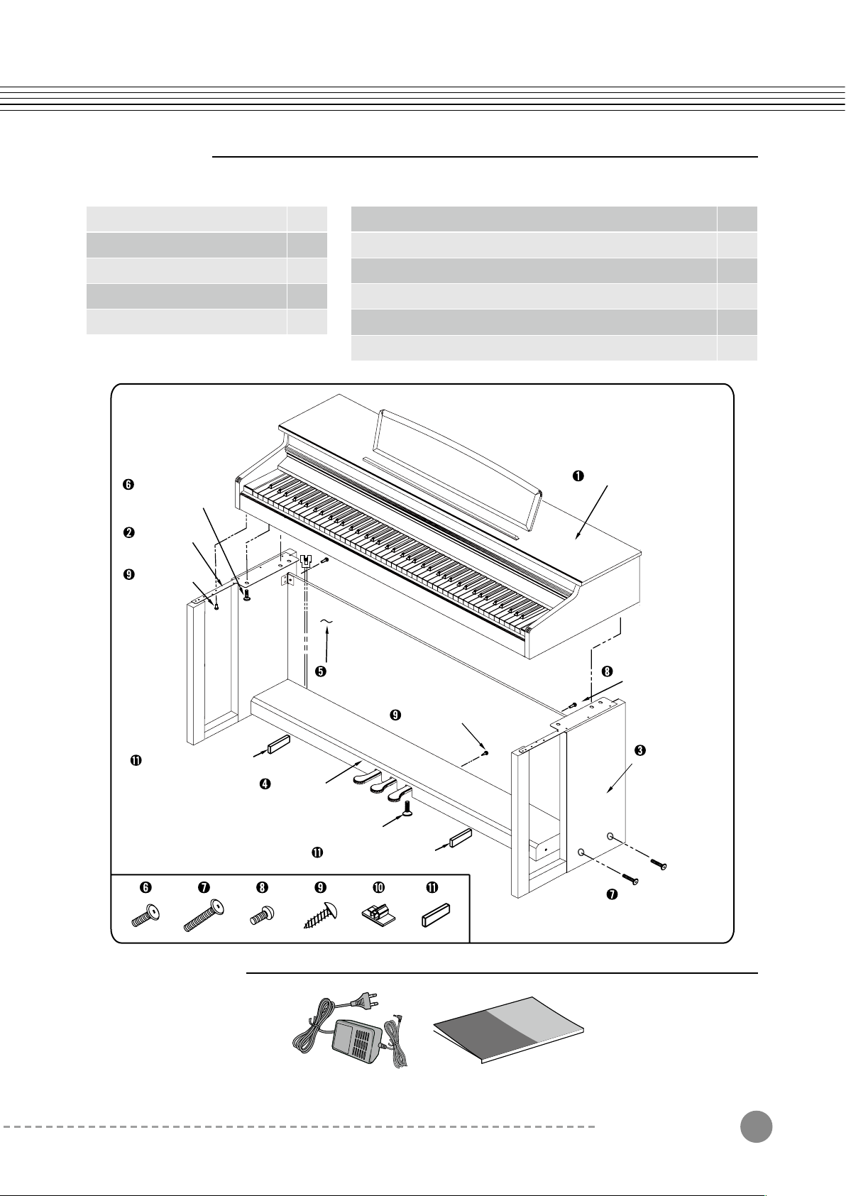
Components
Please check the components below
❶ Piano Body
❷ Side Pannel(Left) Stand
❸ Side Pannel(Right) Stand
❹ Pedal Box
❺ Back Panel
Side Pannel Stand &
Piano Body Set Bolts
Side Pannel
(Left) Stand
Side Pannel
Set Screws
1
1
1
1
1
❻ Side Panel(Left/Right) Stand & Piano Body Set Bolts
❼ Side Panel(Left/Right) Stand & Pedal Box Set Bolts
❽ Back Panel Set Bolts
❾ Back Panel & Pedal Box/Piano Body Set Screws
❿ Cable Clamps
⓫ Pedal Box Supports
Piano Body
4
4
2
6
2
2
Pedal Box Supports
Carton Contents
Pedal Box
Back Panel
Pedal Bolt
Pedal Box Supports
Back Panel Set Bolts
Back Panel Set Screws
Side Pannel
(Right) Stand
Pedal Box Set Bolts
DC Power Adapter User’s Manual
Assembly Instructions
7
Page 8
Chapter2
Assembly Instructions
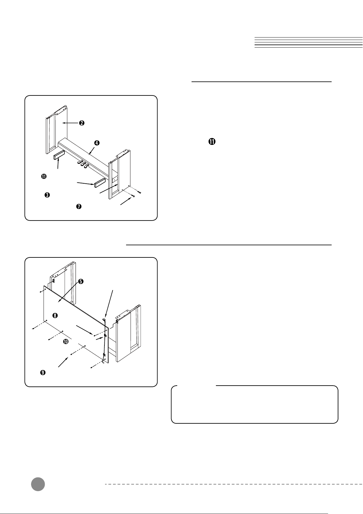
Assembling Left/Right Side Panel Stand
1) Put the cable in the Pedal Box➍ out.
Side Panel(Left) Stand
Pedal Box Support
Side Panel(Right) Stand
Pedal Box
Pedal Box Set Bolt
2) Starting with the left stand leg➋ ,
place the Pedal Box➍ on the Pedal Box
Supports , align the holes in the Pedal Box
with the holes in the Stand Leg, then thread
the Pedal Box Set Bolts➐ into the holes.
3) Repeat with the right stand➌ and tighten all bolts
fully.
➍
Assembling Back Panel
Back Panel
Back Panel
Set Bolt
Cable Clamps
Back Panel Set Screw
Pedal Cable
1) Place the Back Panel➎ on the assembled stand
legs. Align the holes in the Back Panel➎ with the
bracket in the stand legs, then fasten them by
using the Back Panel Set Bolts➑ as shown.
2) Attach the Pedal Box➍ to the bottom of the Back
Panel➎ and thread the Back Panel Set Screws
➒
into the 4 holes.
3) After placing the Cable Clamps➓ over the pedal
cable, stick it on the back panel, then arrange
the cable behind the Back Panel➎.
Caution
Please arrange the pedal cable after completely
assembling the back panel with the side panel
and pedal box.
Assembly Instructions
8
Page 9
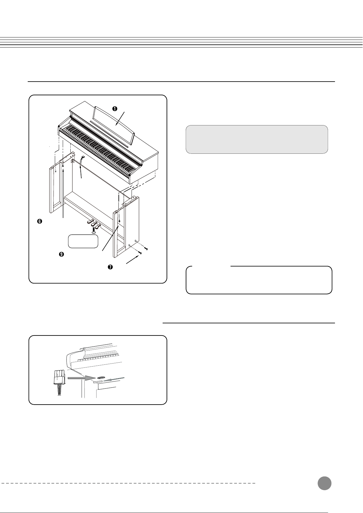
Piano Body
1) After putting the Piano Body on each side of
the stand, align the 4 holes in the stands with
the holes in the bottom of the Piano Body.
Before tighten up the bolts, do not press
Piano Body (especially for keys).
The body may fall forward.
2) Fix them by using the Set Bolts➏.
Pedal Cable
Side Panel Stand
& Piano Body Set Bolt
Pedal Bolt
Caution
Side Panel Set Screw
Pedal Box Set Bolts
How to connect Pedal Cable
3) Thread the Side Panel Set Screw➒ into the
hole in the connecting bracket (front Stand).
4) Connect the Pedal Cable with the pedal
terminal in the Piano Body.
5) After decide the place for the piano, loose the
Pedal Bolt when it goes to the ground to avoid
damaging the Pedal Box with playing the piano.
Warning
Unless you loose the Pedal Bolt, it can be
damaged.
Insert the pin until it makes a “Tick” sound.
If the pin is bent or is not completely connected,
the Pedal will not work.
● When the assembly is complete, connect the pedal cable to the port in the bottom of piano body
● If the pedal cable is not completely connected, the pedal will not work.
● Dress the pedal cable by using the cable clamps.
After decide the place for the piano, loose the pedal bolt when it goes to the ground to avoid damaging
the pedal box with playing the piano.
Assembly Instructions
9
Page 10
Chapter2
Assembly Instructions
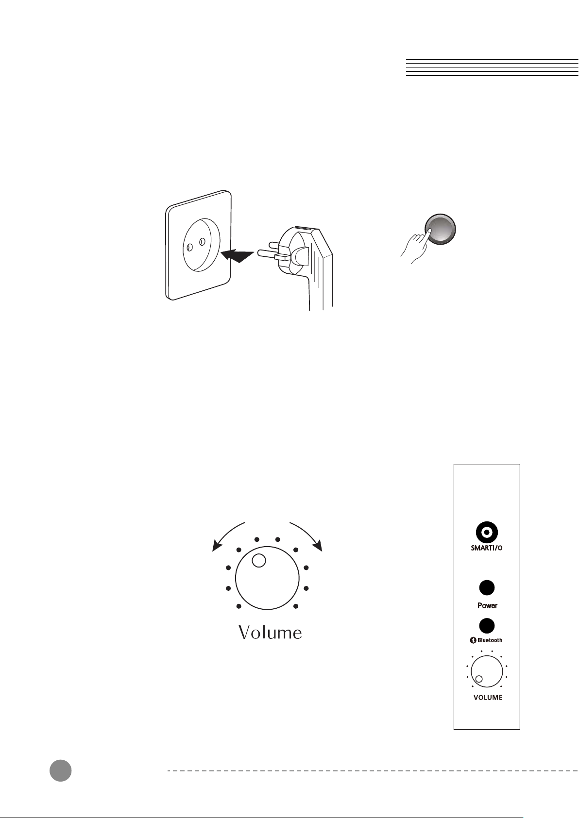
2. Power Connection
Power
MP120A uses a free voltage(110V~240V) power adaptor.
Before connecting the AC power cord, please check whether the power switch is
"Off " or not.
When the MP120A is set up, turn the power on. After a couple of seconds, the LCD
screen will show the current state and the [Piano] button will light up.
The MP120A is now ready to play.
3. Master Volume
Volume Control is located on the right end of the keyboard.
Turn this knob from left to right (clockwise) to increase the volume,
the volume increases and vice versa.
Assembly Instructions
10
Page 11

1. Main Button
Chapter3
Left Panel
(1) Piano Button
Press this button to bring a piano voice at any time.
(2) Voice Button
This instrument features exceptionally realistic 30 voices.
After pressing the [Voices] button, choose a voice you desire by
using the [Next] or [Previous] button.
Press and Hold the [Voices] button to enter GM Sound Mode.
Auto Layer
GM
(3) Layer Button
Layer Mode allows you to layer two different Program sounds on
the keyboard.
(4) Duo Button
Duo Mode allows you to split the keyboard into two regions, each
transposed to the same range for 4-hand use (ideal for duets or
instructors and students).
(5) Split Button
Split Mode allows you to split the keyboard into two regions
containing two different Program sounds, with adjustable split point.
(6) Demo Button
Demo Mode allows you to hear a selection of demo songs performed
in a variety of classical styles.
(7) Metro/Rhy button
Metronome/Rhythm mode allows you to select whether a Metronome
and/or Rhythm will be played.
(8) Record Button
Press this button to record your performance in real time.
User songs can immediately be stored in internal track.
(9) Play/Stop Button
Press this button to start or stop recording or demo songs.
(10) Next Button
Use these buttons to select the next voice or demo song. In Function
mode, the parameter increases by one with pressing this button.
(11) Previous Button
Use these buttons to select the previous voice or demo song.
In Function mode, the parameter decreases by one with pressing this
button.
Left Panel
11
Page 12

Chapter4
Voice & Piano
1. Selecting a Voice
Edu
GM
You can make use of the [Voices] and [Piano] buttons.
1) Press the [Voices] button.
2) Select a voice you want by using the [Next] or
[Previous] button.
If you want to play with a piano voice, press the [Piano]
Button. You can immediately bring “Concert Piano’
sound (rst voice) at any time.
The selected values (Layer, Split, Duo, Reverb and
Effect) will be initialized.
The name of a selected voice will be displayed in the
LCD screen.
2. Voice List
No Voices Auto Layer Voices Splits Voices
1 Concert Piano 49 String Ensemble2
2 Grand Piano 49 String Ensemble2
3 E.Piano 1 88 New age Pad
4 E.Piano 3 88 New age Pad
5 Harpsichord 88 New age Pad
6 Vibraphone 88 New age Pad
7 Pop Organ 60 French Horn
8 Church Organ 60 French Horn
9 Reed Organ 60 French Horn
10 A.nylon 0 Grand piano
11 Steel Guitar 0 Grand piano
12 Overdrive 0 Grand piano
13 A bass 116 Taiko Drum
14 Finger bass 116 Taiko Drum
15 Slap Bass 116 Taiko Drum
33 Acoustic
Bass
No Voices Auto Layer Voices Splits Voices
16 Violin 60 French Horn
17 Cello 60 French Horn
18 Pizzicato 60 French Horn
19 String 0 Grand piano
20 Synth string 0 Grand piano
21 Choir Aahs 0 Grand piano
22 Trumpet 40 Violin
23 Brass 40 Violin
24 Alto sax 40 Violin
25 Oboe 49 String Ensemble2
26 Flute 49 String Ensemble2
27 Ocarina 49 String Ensemble2
28 Fantasia 9 Celesta
29 Crystal 9 Celesta
30 Drum set
33 Acoustic
Bass
3. Selecting a GM Voice
Press and Hold the [GM] button to enter GM Voice Mode. Then the screen will show a current
GM voice and the [Voice] button will light up. Select a voice you want by using the [Next] or
[Previous] button. At this moment, Auto Layer, Split and Duo Modes are disabled.
See page 30 to check GM Sound List.
12
Voice & Piano
Page 13

Chapter5
Layer Mode
Using Layer Mode
Layer Mode allows you to combine two different voices on the keyboard.
If you press the [Auto Layer], an auto layer voice will
be selected. Press the [Next] or [Previous] button to
select one other layer voice. You can also use 128
GM voices to create a layer sound.
Press the [Voices] button, then select a basic voice
you want to use by pressing the [Next] or [Previous]
button. At this moment, the selected voice cannot
GM
be changed. Press the [Piano] button to exit Layer
mode.
Auto Layer
Volume
GM
Auto Layer
In this mode, an auto layer voice can automatically
be selected (based on the currently selected voice,
the auto layer voice is selected).
To check auto layer voices, see the voice list on the
previous page.
LAYER Volume:
When two voices are layered, press the [Volume]
button. You can now adjust the volume by using
the [Next] or [Previous] button.
Default Layer Volume: 80
Adjustable Volume Range: 20 ~ 120
Auto Layer
Layer Mode
13
Page 14

Chapter6
Split Mode
Using Split Mode
Split mode allows you to split the keyboard into two regions containing two different voice
sounds, with adjustable split point.
Select a basic voice you want to use by using the
[Voices] or [Piano] button. (This voice is for the right
region of the keyboard.)
If you press the [Split] button, you can play A.Bass
voice for the left region of the keyboard.
Press the [Next] or [Previous] button to select another
GM
Auto Layer
voice in 128 GM voices for the left region.
To change the voice is for the right region, press the
[Voices] button. Then select a voice you want to use
by using the [Next] or [Previous] button.
Press the [Piano] button to exit Split mode.
Auto Layer
GM
Split Volume:
When two voices are split, press the [Volume] button.
You can now adjust the volume by using the [Next] or
[Previous] button.
Default Split Volume: 100
Adjustable Volume Range: 20 ~ 120
The selected split voice automatically goes one
octave up.
Split Point:
To set the split point, press and hold the [Split] button
for 3 seconds. Then select a key on your keyboard
as a split point when the screen shows “STRIKE A
KEY”.
14
Split Mode
Page 15

Function Mode
Chapter7
Function Button
1
2
3
4
5
6
7
Style Volume
Accompaniment
Using Function Mode
Reverb
Eect
Eect Level
Tune
Touch
8
9
10
11
12
13
Demo Loop
Temperaments
Local Control
Damper Resonance
String Resonance
Auto Power O
Press the [Layer], [Split], and [Function] button
simultaneously.
In the Sub Menu of Function mode, you can choose
one of the 13 functions by the [Layer] or [Split] button.
Auto Layer
GM
If you want to change each parameter on Sub Menu,
use the [Next] or [Previous] button.
■
If you turn the Function mode off and on again,
the last used function setting will run.
Function Button
15
Page 16

Chapter7
Function Button
1. Style Volume
This function will adjust the accompaniment volume, so as to keep an appropriate
balance between the accompaniment volume and the voice volume.
Press the [Function] button.
Select “Acc Volume” by pressing the [Layer] button, then control the volume by
pressing the [Next] or [Previous] button.
The volume range is from 0 (minimum) to 100 (maximum).
The default volume setting is “70”.
2. Accompaniment
You can turn on/off the automatic accompaniment.
Press the [Function] button.
Select “Accompaniment” by pressing the [Layer] button, then turn it on or off by
pressing the [Next] or [Previous] button.
The default setting is “Acc On”, which means you are ready to start the automatic
accompaniment. If the LCD display shows “Acc Off”, the accompaniment is turned off
and only rhythm pattern is played.
3. Reverb
You can select a type of Reverbs.
Press the [Function] button.
Select “Reverb” by pressing the [Layer] button, then select a reverb type by pressing
the [Next] or [Previous] button.
The default setting is “Room 1”.
Selectable Reverb: Off, Room 1, Room 2, Hall 1, Stage
4. Effect
You can select a type of Effects.
Press the [Function] button.
Select “Effect Off” by pressing the [Layer] button, then select an effect type by
pressing the [Next] or [Previous] button.
The default setting is “Off”.
Selectable Effect: Off, Chorus, Phaser, Tremolo, Rotary
5. Effect Level
You can control the level of Effects.
Press the [Function] button.
Select “Effect Level” by pressing the [Layer] button, then select an effect level by
pressing the [Next] or [Previous] button.
The default setting is “60”.
You can adjust the effect level from 0 to 127.
Function Button
16
Page 17

6. Tune
You can tune the pitch of your instrument to match other instruments.
Press the [Function] button.
Select “Tune” by pressing the [Layer] button.
To control the value, press the [Next] or [Previous] button.
The default setting is “440”.
Tuning setting range: 427 – 440 – 453
By pressing the [Next] and [Previous] buttons simultaneously, you can reset to the
default setting (“440”) quickly.
7. Touch
You can adjust the keyboard touch sensitivity to your playing technique.
Press the [Function] button.
Select “Touch” by pressing the [Layer] button.
To control the Touch level, press the [Next] or [Previous] button.
The default setting is “normal 2”.
You can use a total of 10 Touch settings to the following settings:
Soft 1~3, Normal 1~3, Heavy 1~3, Fixed
8. Demo Loop
You can set the repeat options for demo songs.
Press the [Function] button.
Select “Demo Repeat” by pressing the [Layer] button.
To change the setting, press the [Next] or [Previous] button.
The default setting is “All Repeat”.
Demo Loop Type
1. No : Demo Loop in not active.
2. One : Only one demo song is repeated.
3. All : All demo songs are repeated from the selected song.
9. Temperament
You can change Temperament.
Press the [Function] button.
Select “Temperament” by pressing the [Layer] button.
To change the setting, press the [Next] or [Previous] button.
The default setting is “Equal”.
Temperament Type
1. Equal
2. Pythagorean
3. Pure Major
4. Pure Minor
5. Meantone
6. Werckmeister
7. Kimberger
Function Button
17
Page 18

Chapter7
Function Button
10. Local Control
The Local control allows you to control whether your keyboard will trigger the internal
sound engine. Usually Local control should be set to On. When using the MP120A to
record to an external sequencer or computer, turn this setting to Off to avoid creating
a MIDI loop which may result in stuck notes or “echoes”.
You can turn on/off piano sounds.
Press the [Function] button, then select “Local” by pressing the [Layer] button.
The default setting is “On”.
To turn on/off Local Control, press the [Next] or [Previous] button.
Local Control Type: On, Off
11. Damper Resonance
This pedal function performs the same function as the damper pedal on an acoustic
piano, letting you sustain the sound of voices even after releasing the keys.
Press the [Function] button to select Damper Resonance.
The screen shows “100 Damper Resonance”, which is the default setting.
You can adjust the resonance level from 0 (no effect) to 100.
12. String Resonance
You can simulate sympathetic string resonance in an acoustic piano.
Press the [Function] button to select String Resonance.
The screen shows “30 String Resonance”, which is the default setting.
You can adjust the resonance level from 0 (no effect) to 120.
13. Auto Power Off
You can use 4 types of “Auto Power Off” settings to the following settings:
1. OFF: Auto Power Off is set to off.
2. 1Hr: MP120A will automatically power off after the Power Off time (1 hour)
has expired (Default).
3. 2Hr: MP120A will automatically power off after the Power Off time (2 hours)
has expired.
3. 3Hr: MP120A will automatically power off after the Power Off time (3 hours)
has expired.
18
Function Button
Page 19

Chapter8
Record button/Duo Mode
With the easy-to-use song recording features, you can record your own keyboard
performances as a user song.
By recording your performance with various voices, you can improve your playing skill
or composing and arranging skills. Furthermore, you can enjoy playing with a previously
recorded song.
1. How to Record
Method 1:
1) Press the [Record] button.
2) The LED on the [Play/Stop] button will be lit.
3) Start recording and perform the song.
4) Press the [Play/Stop] button to stop the recording.
5) If Press the [Play/Stop] button again, the recorded
song is played.
2. Erasing the Recording
1) Press the [Record] button for 2-3 seconds. The screen will show “Clear”, then the
user song will be erased.
2) If you restart recording, a previously recorded song is automatically deleted, then
you can record a new song.
3. Duo Mode
Dual Mode allows you to split the keyboard into two
regions, each transposed to the same range for 4-hand
use. (ideal for duets or instructors and students)
GM
Auto Layer
Press the [Duo] button.
The screen will display “Duo Piano”.
Piano voice is selected and the keyboard regions are
split at the E4 key.
In Duo Mode, the soft pedal functions as sustain pedal
for the left region of the keyboard.
Record Button/Duo Mode
19
Page 20

Chapter9
Demo Mode/EDU Button
Starting Demo Songs
Playing Educational Songs
GM
Auto Layer
1) Press the [X-pose] and [Record] buttons together.
2) The LED on the [X-pose] and [Record] will ash.
3) Select a teaching material (see page 28-29) by
pressing the [Next] or [Previous] button.
4) Press the [PLAY/STOP] Button to play the demo song
you choose.
5) Press the [PLAY/STOP] Button again to stop the demo
song.
If you want to repeat the demo song, see the information on
Demo Loop.
1. No: Demo Loop in not active.
2. One: only one demo song is repeated.
3. All: all demo songs are repeated from the selected song.
1) Press the [X-pose] and [Record] buttons together.
2) Press the [Voices] button.
3) The LED on the [Voices] button will ash. Press the
[Layer] or [Split] button to select a teaching material.
4) You have a choice among Beyer or Czerny 100/30/40,
Sonatine, Hanon, Burgmuller.
5) Select a song in each teaching material by pressing the
[Next] or [Previous] button.
6) Press the [Play/Stop] Button to play an educational song
you choose.
7) Press the [Play/Stop] Button again to stop the educational
song.
8) To exit EDU mode, press the [Edu] button.
Demo Mode/ EDU Button
20
■
Left/Right Part Learning
Press the [EDU] button for 2-3 seconds, then select a
hand-part you want to practice by pressing the [Next]
or [Previous] button.
ALL PLAY: Play both tracks (left-hand and right-hand)
RIGHT PLAY: Only play the right-hand part.
LEFT PLAY: Only play the left-hand part.
■
To enjoy part learning
Press the [EDU] button for 2-3 seconds, then play an
educational song to start part learning.
Page 21

Chapter10
Metronome/Transpose
Starting Metronome(Rhythm)
Press the [Metro/Rhy] button for 2-3 seconds.
At this moment, you can choose one of 6 metronomes
and 20 rhythms by using the [Next] or [Previous] button.
Auto Layer
To stop the metronome, press the [Metro/Rhy] button
again. Please see the types of metronome and rhythm
list below :
■
for Fill-In and Intro/Outro respectively.
■
■
While playing a rhythm : The left/middle pedal can be used
Fill-in : If you press the middle pedal, when a rhythm is
started, a different rhythm pattern will be played after
one-measure interlude.
Intro/Outro : If you press the left pedal, the [Metro/Rhy]
button will blink, then the Intro will begin with a rhythm.
While playing, if you press the left pedal, the rhythm will stop.
Rhythm List
Press the [Metro/Rhy] button for 2-3
seconds, then select a rhythm by using the
[Next] or [Previous] button.
No Rhythm
1 Dance
2 Light Rock
3 Pop
4 Pop Polka
5 Hard Rock
6 Country
7 Rhumba
8 8Beat
9
10 Ballade
16Beat
No Rhythm
11 Bosanova
12 Samba
13 March
14 Waltz
15 ChaCha
16 Reggae
17 Jazz
18 Rhythm Beat
19
20 Fox Trot
Swing Rock
Transpose
This button will allow you to adjust the tuning of the keyboard in semitones, to a desired
interval.
By using the [X-Pose +] or [X-Pose +] button, you can
transpose down or up by one semitone (100 cents).
When transpose value goes up, the LED on the [X-Pose +]
button will be lit. When transpose value goes down,
the LED on the [X-Pose -] button will be lit.
Transpose Value Range: -24 ~ 0 ~ +24
The value more or less than the adjustable range cannot
be done.
Metronome/Transpose
21
Page 22

Chapter11
Pedal
1. Pedal
MP120A contains three functional pedals. It also works the same way with Grand Piano.
Therefore, this product do not support the Silent Pedal (the middle pedal) of Upright Piano.
You can control the volume as a function of Silent Pedal.
2. Pedal Type
Soft Sostenuto
1. Sustain Pedal
When the sustain pedal is pressed, notes sustain longer.
Releasing the pedal immediately stops any sustained notes.
2. Soft Pedal
When the soft pedal is pressed, all notes played on the
keyboard will have a softer effect.
3. Sostenuto Pedal
When the sostenuto pedal is pressed, the notes played
before you step on the pedal would have a sustain effect.
NOTE
If you are having problems with using your pedals,
please check the connection between the piano body
and pedal box. (see Page 12 for more details.)
3.
By Bluetooth, MP3 les of smart phone and sound sources on
Youtube can be played on your MP120A.
Sustain
Press the pedal from this point
Press the pedal from this point
22
1) Press the [Bluetooth] button, then the LED will bink with a
“beep” sound.
2) Set Bluetooth of your device to On.
3) Your device will automatically connect to your MP120A
(“SM-BT Audio”), blinking the LED for a second.
4) When the connection is completed, you can play the sound
les or sources of your device through your MP120A.
5) You can control the volume by your device or MP120A.
6) To stop Bluetooth, press the [Bluetooth] button again.
Pedal
Page 23

Chapter12
MIDI
MIDI is the acronym for Musical Instrument Digital Interface. It is the industry standard
protocol which allows the exchange of musical data between electronic musical instruments,
devices (such as a sequencer), and computers.
1. MIDI Channel
MIDI protocol transmits multiple channels of MIDI performance data.
Typical MIDI instruments can play up to 16 channels at the same time.
Each channel can be assigned its own Program.
2. MIDI Connection
In addition to the conventional MIDI In and Out ports, MP120A has a USB port.
You can connect the MP120A directly to a computer with a USB cable.
To use the MP120A as a MIDI controller with a computer, use any Type-A to Type-B
USB cable.
(your computer) (your piano)
3. Local Control
The Local control allows you to control whether your keyboard will trigger the internal
sound engine. Usually Local control should be set to On. When using the MP120A to
record to an external sequencer or computer, turn this setting to Off to avoid creating
a MIDI loop which may result in stuck notes or “echoes”.
MIDI
23
Page 24

MIDI Implementation Chart
24
MIDI
Page 25

Chapter13
Connectors
1. Headphone
The headphone jack is located on the bottom left of keyboard.
You will need a 1/4-inch stereo jack in order to use headphones and can use two
headphones simultaneously. To avoid the risk of hearing loss when using headphones,
please do not play the piano with a high volume level for a long time.
The bottom of your piano
Stereo headphone jack
2. Audio In
Connect the audio output of an MP3/CD player or other audio Source to the stereo
AUX IN jack on the rear panel. You will be able to hear the music through the speaker
of your keyboard.
3. Audio Out
Audio Out ports can be used to transmit the audio signal of the piano to a keyboard
amplier, stereo sound system, mixing console or tape recorder. When you connect
an audio speaker, please ensure that the volume has been set to the minimum level.
C
USB
MIDI
IN/OUT
INPUT
OUTPUT
MI OWER
VOL IN
DC IN 24V
4. Smart Recording(I/O)
Connect the Smart Recording cable to the Smart I/O port on
the right panel of your keyboard, then connect the cable with
your smartphone. Now you can record the piano sound on
your smartphone with the recording function. When you play
the contents of your smartphone, you can hear them through
the amp of MP120A.
NOTE
When you connect the Smart Recording cable, please ensure that the volume is set
to the minimum level or is turned off because noise can suddenly be produced.
The recorded volume can be different depending on the model of your device.
Thus, it is recommended to set the volume in the 12 o’clock position.
Connectors
25
Page 26

Chapter14
Percussion Placement
26
Percussion Placement
Page 27

Chapter15
Demo Song List
1 Prelude I BWV 846 J.S. Bach
2 Invention No.4 J.S. Bach
3 Invention No.8 J.S. Bach
4 BWV 847 Prelude II BWV 847 J.S. Bach
5 ARIA Goldenberg - Variationen BWV 988 J.S. Bach
6 BWV 848 Fuga II (A3 VOCI) J.S. Bach
7 Op.36, No.4 Sonatine Op.36, No.4 M.Clementi
8 K.15v Klavierstuck K.15v W.A. Mozart
9 K.333 Piano Sonate K.333 1st mov. W.A. Mozart
10 K.485 Rondo in D-dur K.485 W.A. Mozart
11 Piano Sonate K.331 Rondo Turkish March W.A. Mozart
12 K 545 Piano Sonate K.545 1st mov. W.A. Mozart
13 Minuette in G L.v. Beethoven
14 Bagatelle No.25 Fur Elise L.v. Beethoven
15 Op.55, No.1 Sonatine Op.55, No.1 Fr. Kuhlau
16 March Militaire Op.51, No.1 F.P. Schubert
17 Op.94 - 3 Moments Musicaux 3. F.P. Schubert
18 Op.90 - 2 Impromptu Op.90, No.2 F.P. Schubert
19 Op.90 - 4 Impromptu Op.90, No.4 F.P. Schubert
20 La chevaleresque J.F.Buramu ler
21 Op.38, No.2 Without words song Op.38, No.2 J.L.F. Mendelssohn
22 Op.30, No.6 Venetianisches Zgondellied J.L.F. Mendelssohn
23 KK lvb - 10 Sostenuto F.F. Chopin
24 KK lvb - 11 Valse KK IVB - 11 F.F. Chopin
25 Op.7, No.1 5 Mazurkas I Op.7, No.1 F.F. Chopin
26 Op.69 - 2 Valse Op.69, No.2 F.F. Chopin
27 Op.18 Grande Valse Brillante Op.18 F.F. Chopin
28 Valse Op.64, No.2 F.F. Chopin
29 Op.9, No.2 Noctutne Op.9, No.2 F.F. Chopin
30 Op.64, No.1 Valse Op.64, No.1 F.F. Chopin
31 Op.28, No.15 Preludes in Db Maior Op.28, No.15 F.F. Chopin
32 Op.66 Fantaisie - Impromptu Op.66 F.F. Chopin
33 Op.15 - 7 Traumerei R. Schumann
34 Frolicher Landmann Op.68 - 10 R. Schumann
35 Op.15 Von fremden Landern und Menschen Op.1 R. Schumann
36 Liebestraume Nr.3 F. Liszt
37 Dolly's Dreaming And Awakening T. Oesten
38 Op.410 Fryhlingsstimmen Op.410 J. Strauss
39 The Swan Saint - Saens
40 Blumenlied G. Lange
41 Valsette F. Borowski
42 Op.39, No.16 Old French Air P.I.Tchaikovsky
43 Op.39, No.10 Mazurka P.I.Tchaikovsky
44 Polka P.I.Tchaikovsky
45 Barcarolle P.I.Tchaikovsky
46 Op.101 - 7 Humoreska A. Dvor A k
47 Op.46 - 3 Suite Peer Gynt Op.46 - 3 Anitras Tanz E. Grieg
48 L75 Suite Bergamasque Prelude C.A.Debussy
49 Reverie C.A.Debussy
50 Arabesque C.A.Debussy
Demo Song List
27
Page 28

Chapter16
Sonatine List
Kuhlau Number
OP. 20 N0. 1-1 1
OP. 20 N0. 1-2 2
OP. 20 N0. 1-3 3
OP. 20 N0. 2-1 4
OP. 20 N0. 2-2 5
OP. 20 N0. 2-3 6
OP. 20 N0. 3-1 7
OP. 20 N0. 3-2 8
OP. 20 N0. 3-3 9
OP. 55 N0. 1-1 10
OP. 55 N0. 1-2 11
OP. 55 N0. 2-1 12
OP. 55 N0. 2-2 13
OP. 55 N0. 2-3 14
OP. 55 N0. 3-1 15
Haydn Number
HOB.16 - 35 - 1
HOB.16 - 35 - 2
HOB.16 - 35 - 3
Mozart Number
K .545 - 1 37
K .545 - 2 38
K .545 - 3 39
Beethoven Number
OP. 49 N0. 2-1 40
OP. 49 N0. 2-2 41
OP. 49 N0. 1-1 42
OP. 49 N0. 1 -2 43
Dussek
OP. 20 N0. 1 -1 44
OP. 20 N0. 1 -2 45
34
35
36
Number
OP. 55 N0. 3-2 16
Clementi Number
OP. 36 N0. 1-1
OP. 36 N0. 1-2
OP. 36 N0. 1-3
OP. 36 N0. 2-1
OP. 36 N0. 2-2
OP. 36 N0. 2-3
OP. 36 N0. 3-1
OP. 36 N0. 3-2
OP. 36 N0. 3-3
OP. 36 N0. 4-1
OP. 36 N0. 4-2
OP. 36 N0. 4-3
OP. 36 N0. 5-1
OP. 36 N0. 5-2
17
18
19
20
21
22
23
24
25
26
27
28
29
30
28
OP. 36 N0. 5-3
OP. 36 N0. 6-1
OP. 36 N0. 6-2
Sonatine List
31
32
33
Page 29

Chapter17
GM Sound List
Program
Change
1
2
3
4
5
6
7
8
9
10
11
12
13
14
General MIDI
Sound Name
Grand Piano1
Grand Piano2
Electric Grand
Honky Tonk
Electric Piano1
Electric Piano2
Harpsicord
Clavinet
Celesta
Glockenspiel
Music Box
Vibraphone
Marimba
Xylophone
Program
Change
33
34
35
36
37
38
39
40
41
42
43
44
45
46
General MIDI
Sound Name
Acoustic Bass
Fingered Bass
Picked Bass
Fretless Bass
Slap Bass1
Slap Bass2
Synth Bass1
Synth Bass2
Violin
Viola
Cello
Contrabass
Tremolo Strings
Pizzicato Strings
Program
Change
65
66
67
68
69
70
71
72
73
74
75
76
77
78
General MIDI
Sound Name
Soprano Sax
Alto Sax
Tenor Sax
Baritone Sax
Oboe
English Horn
Bassoon
Clarinet
Piccolo
Flute
Recorder
Pan Flute
Bottle Chi
Shakuhachi
Program
Change
97
98
99
100
101
102
103
104
105
106
107
108
109
110
General MIDI
Sound Name
Ice Rain
Soundtrack
Crystal
Atmosphone
Brightness
Goblin
Echo Drops
StarTheme
Sitar
Banjo
Shamisen
Kato
Kalimba
Bag Pipe
15
Tubular Bells
16
17
18
19
20
21
22
23
24
25
26
27
28
29
30
Organ1
Organ2
Organ3
Church Organ
Reed Organ
Accordion
Harmonica
Bandoneon
Nylon String Gtr
Steel String Gtr
Jazz Gtr
Clean Gtr
Muted Gtr
Overdrive Gtr
Santur
47
48
49
50
51
52
53
54
55
56
57
58
Slow Strings1
Synth Strings1
Synth Strings2
ChoirAahs
Voice Doo·s
Synth Vox
Orchestra Hit
Trumpet
Trombone
59
60
Muted Trumpet
61
French Horn
62
Harp
Timpani
Strings
Tuba
Brass1
79
80
81
82
83
84
85
86
87
88
89
90
91
92
93
94
Whistle
Ocarina
Square Wave
SawWave
Syn. Calliope
Chier Lead
Charang
Solo Vax
5th SawWave
Bass & Lead
Fantasia
Warm Pad
Polysynth
Space Voice
Bowed Glass
Metal Pad
111
112
113
114
115
116
117
118
119
120
121
122
123
124
125
126
Fiddle
Shanai
Tinkle Bell
Agogo
Steel Drums
Woodblocks
Taiko
Melo Tom1
Synth Drum
Reverse Cym
Gtr Fret Noise
Breath Noise
Seashore
Bird
Telephone
Helicopter
31
32
Distortion Gtr
Gtr Harmonics
63
64
Synth Brass1
Synth Brass2
95
96
Halo Pad
Sweep Pad
127
128
Applause
Gunshot
GM Sound List
29
Page 30

Chapter18
Specifications
Keyboard
Exterior Color Rosewood/ White
Appearance Pattern
Voice Type Stereo PCM
Polyphony 256 Polyphony
Voice 30 Voices + 128 GM Voices
Rhythm 20 Styles (Auto Accompaniment), 6 Rhythms(Metronome)
Function Split, Layer, Duo mode
Touch Sensitivity 10 Steps
Educational Songs
Demo 50 Demo Songs
Recording Record, Start/ Stop (20,000 Notes)
Pedal
88-NOTE, Fully weighted,
Graded Hammer-Action, 3-Point Sensor Keyboard
Beyer, Czerny 100/30/40, Sonatine,
Hanon(20 songs), Burgmuller(25 songs)
Soft Pedal, Sostenuto Pedal,
Sustain Pedal (String/Damper/Resonance)
Display 5 x 7 Dot Matrix
Additional Functions
Connection Terminal
Generating Capacity 5 x 7” WOOFER X 2, 1” TWEETER X 2
Power Consumption 50W
Speaker 5 x 7” WOOFER X 2, 1” TWEETER X 2
Dimensions 1400 x 432 x 850 (W x D x H)
Specication
30
Master Volume, Transpose, Metronome, Tune, Auto Power Off,
MIC Vol, Bluetooth
Headphone x2, Smart I/O(Smart Recording), Aux In/Out,
USB Audio
Page 31

MEMO
MEMO
31
Page 32

196, Bongsu-daero, Seo-gu,
Incheon, Korea
 Loading...