

Page 1
FXAlgs #724-6, 728: Distortion
FXAlgs #724-6, 728: Distortion
FXAlg #724 Ñ Mono Distortion
FXAlg #725 Ñ MonoDistort + Cab
FXAlg #726 Ñ MonoDistort + EQ
FXAlg #728 Ñ StereoDistort+EQ
Small distortion algorithms
Allocation Units: 1 for Mono Distortion; 2 for MonoDistort + Cab; 2 for MonoDistort + EQ;
3 for StereoDistort + EQ
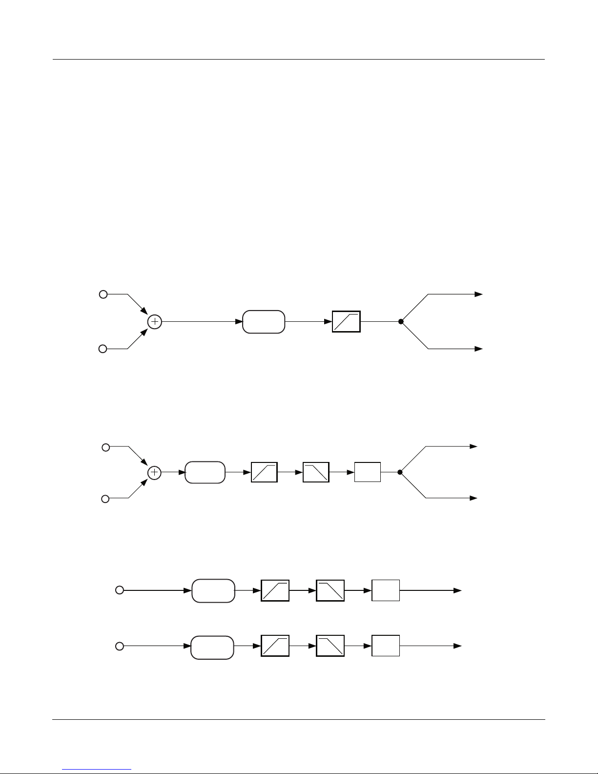
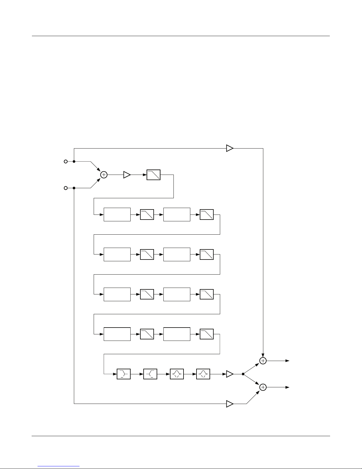
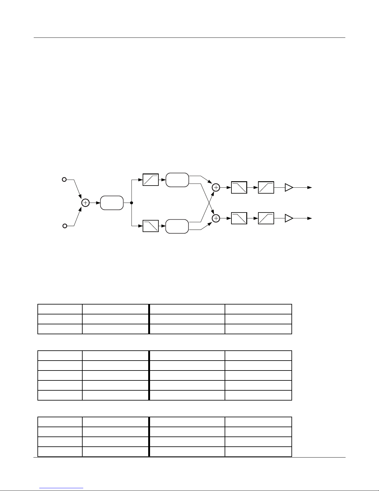
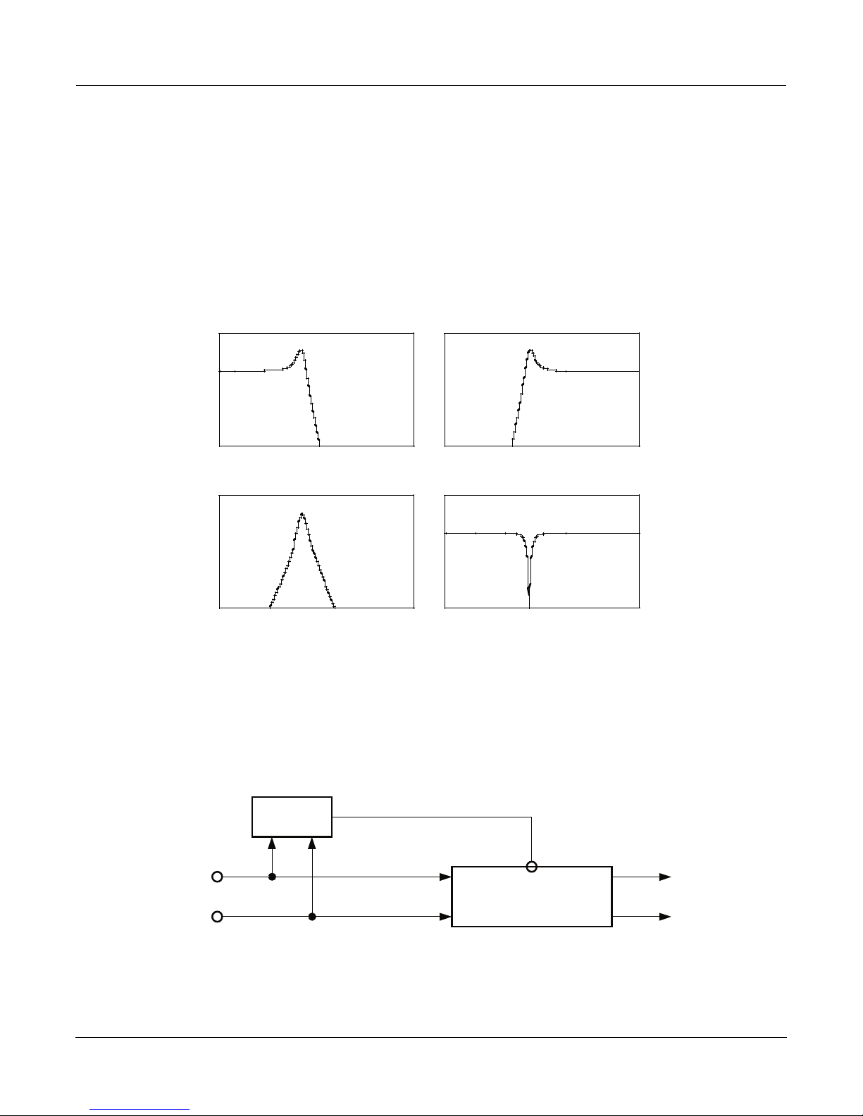
Mono Distortion sums its stereo input to mono, performs distortion followed by a hipass filter and sends the result
as centered stereo.
L Input
Distortion
R Input
Block diagram of Mono Distortion
MonoDistort + EQ is similar to Mono Distortion except the single hipass filter is replaced with a pair of second-order
hipass/lowpass filters to provide rudimentary speaker cabinet modeling. The hipass and lowpass filters are then
followed by an EQ section with bass and treble shelf filters and two parametric mid filters.
L Input
Distortion
R Input
Block diagram of MonoDistort + EQ
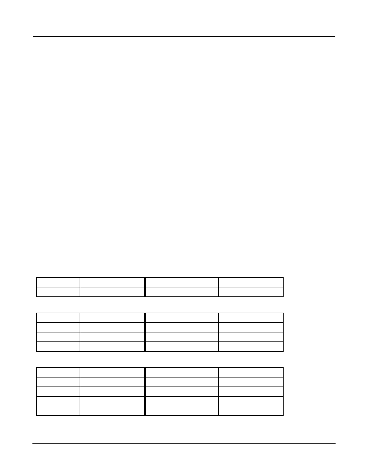
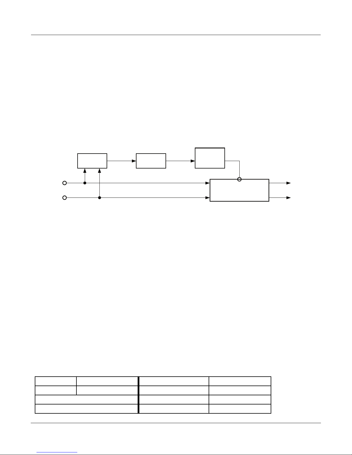
StereoDistort + EQ processes the left and right channels separately, though there is only one set of parameters for
both channels. The stereo distortion has only one parametric mid filter.
Cabinet
EQ
L Output
R Output
L Output
R Output
Distortion
R Input
Algorithm Reference-94
Distortion
Block diagram of StereoDistort+EQ
EQ
EQ
L OutputL Input
R Output
Page 2
FXAlgs #724-6, 728: Distortion
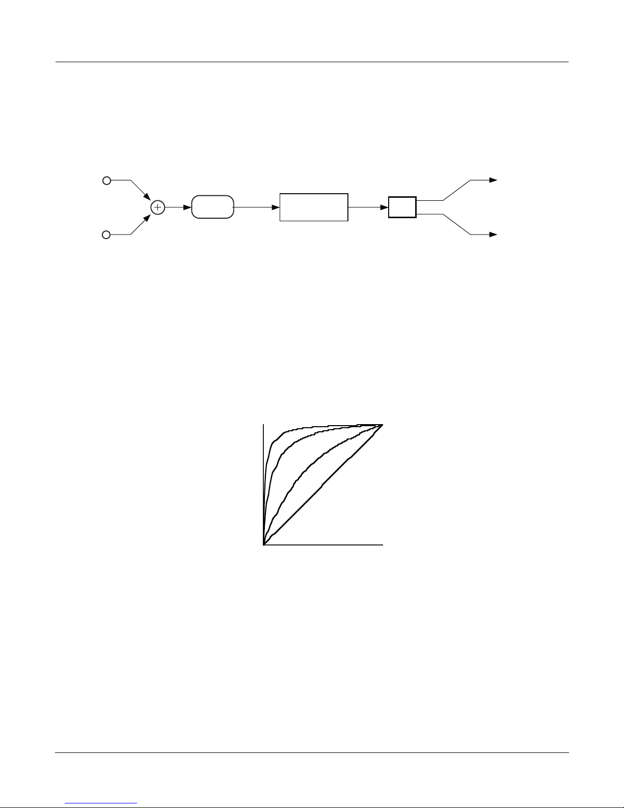
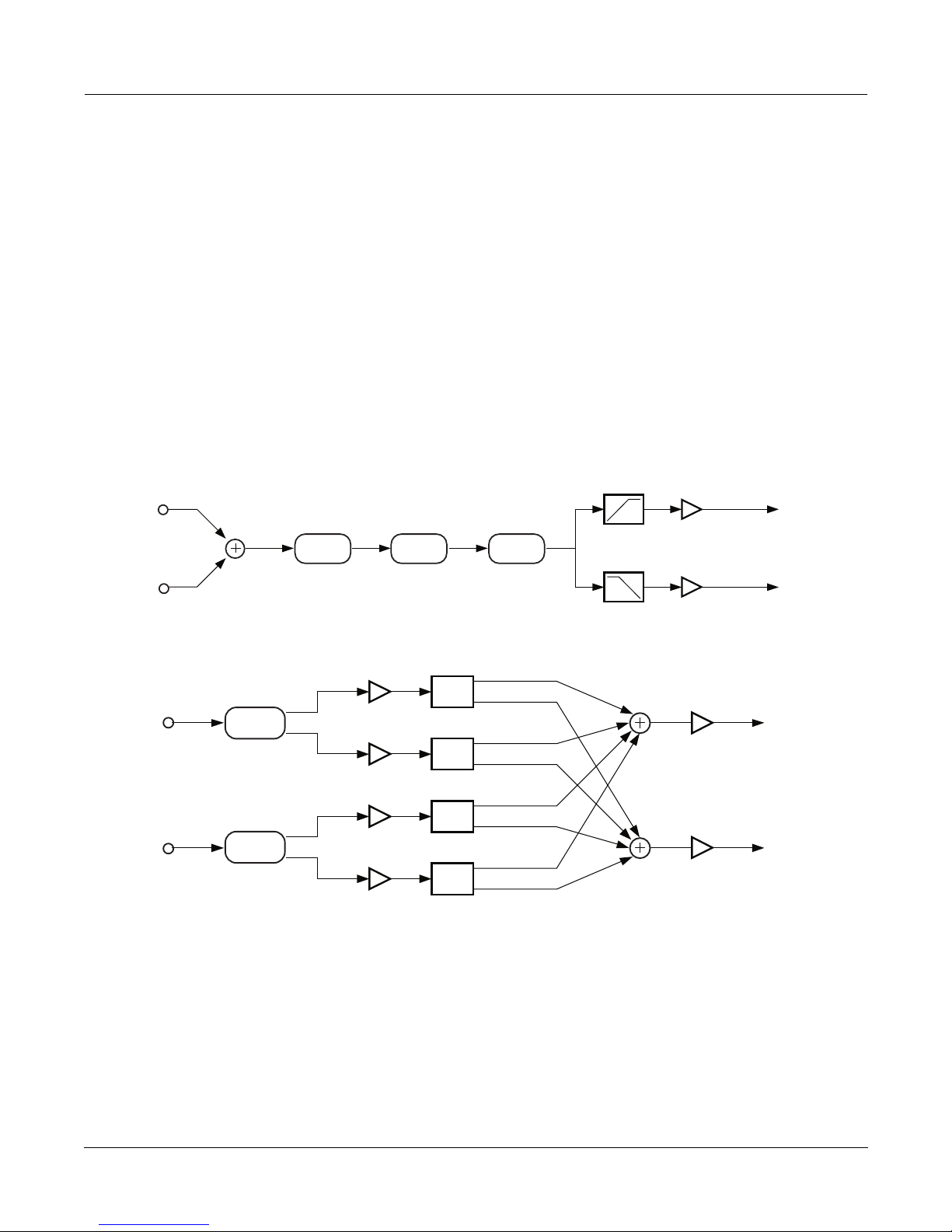
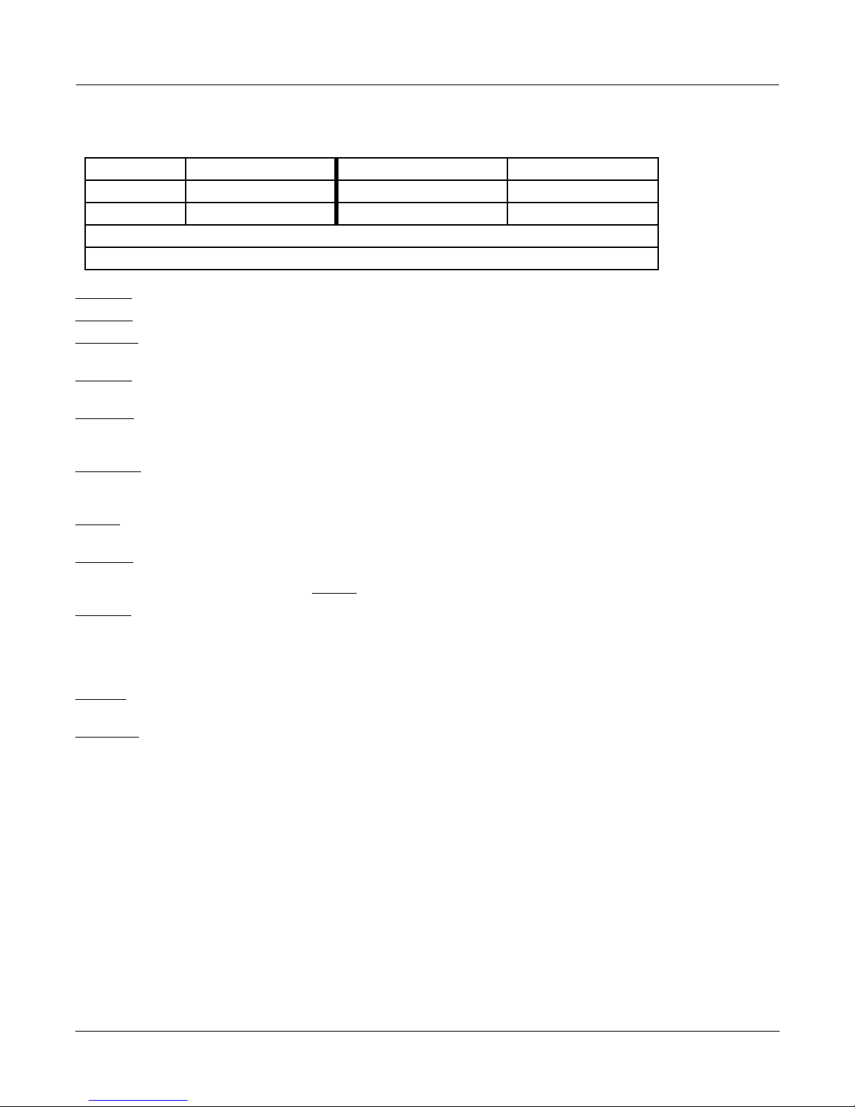
MonoDistort + Cab is also similar to Mono Distortion except the hipass is replaced by a full speaker cabinet model.
There is also a panner to route the mono signal between left and right outputs. In MonoDistort + Cab, the distortion
is followed by a model of a guitar amplifier cabinet. The model can be bypassed, or there are eight presets which
were derived from measurements of real cabinets. (See descriptions of FXAlgs #729-732 in this book for more
information.)
L Input
R Input
Distortion
Cabinet
Filter
Pan
L Output
R Output
Block diagram of MonoDistort + Cab
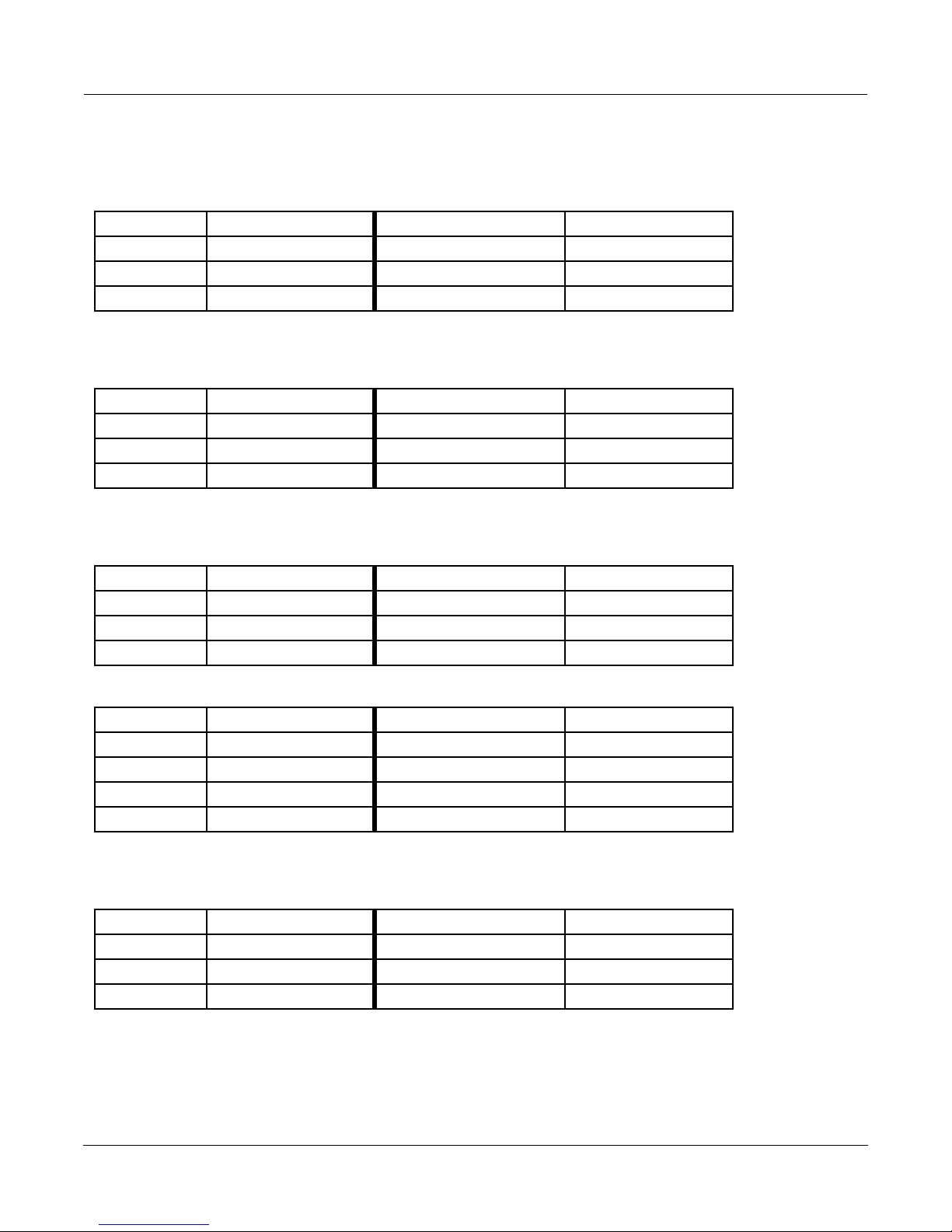
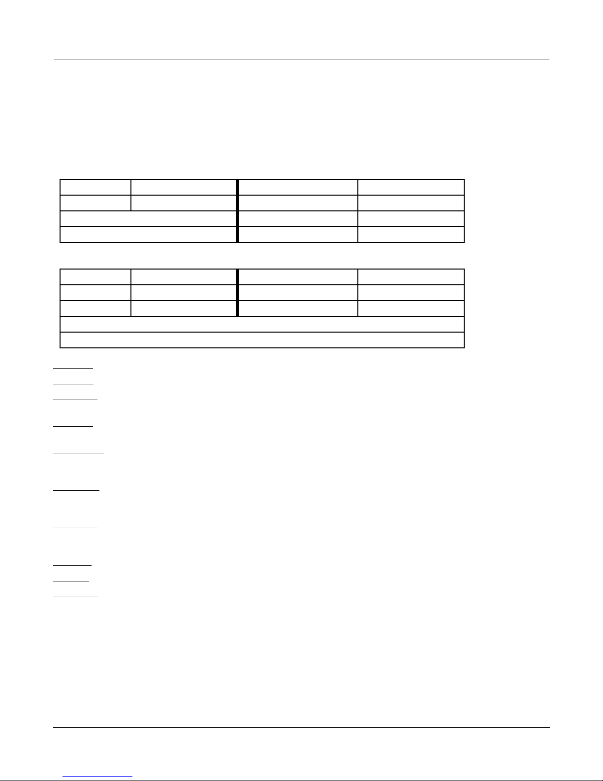
The distortion algorithm will soft clip the input signal. The amount of soft clipping depends on how high the
distortion drive parameter is set. Soft clipping means that there is a smooth transition from linear gain to saturated
overdrive. Higher distortion drive settings cause the transition to become progressively sharper or ÒharderÓ. The
distortion never produces hard or digital clipping, but it does approach it at high drive settings. When you increase
the distortion drive parameter you are increasing the gain of the algorithm until the signal reaches saturation. You
will have to compensate for increases in drive gain by reducing the output gain. These algorithms will not digitally
clip unless the output gain is over-driven.
Output
Input/Output Transfer Characteristic of Soft Clipping at Various Drive Settings
Signals which are symmetric in amplitude (they have the same shape if they are inverted, positive for negative) will
usually produce odd harmonic distortion. For example, a pure sine wave will produce smaller copies of itself at 3,
5, 7, etc. times the original frequency of the sine wave. In the MonoDistort + EQ, a dc offset may be added to the
signal to break the amplitude symmetry and will cause the distortion to produce even harmonics. This can add a
ÒbrassyÓ character to the distorted sound. The dc offset added prior to distortion gets removed at a later point in
the algorithm.
Input
Algorithm Reference-95
Page 3
FXAlgs #724-6, 728: Distortion
Parameters - Mono Distortion:
PAGE 1
Wet/Dry 0 to 100%wet Out Gain Off, -79.0 to 24.0 dB
Dist Drive 0 to 96 dB
Warmth 16 to 25088 Hz
Highpass 16 to 25088 Hz
MonoDistort + Cab:
PAGE 1
Wet/Dry 0 to 100%wet Out Gain Off, -79.0 to 24.0 dB
Dist Drive 0 to 96 dB
Warmth 16 to 25088 Hz Cab Bypass In or Out
Cab Preset Basic
MonoDistort + EQ:
PAGE 1
Wet/Dry 0 to 100%wet Out Gain Off, -79.0 to 24.0 dB
Dist Drive 0 to 96 dB
Warmth 16 to 25088 Hz dc Offset -100 to 100%
Cabinet HP 16 to 25088 Hz Cabinet LP 16 to 25088 Hz
PAGE 2
Bass Gain -79.0 to 24.0 dB Treb Gain -79.0 to 24.0 dB
Bass Freq 16 to 25088 Hz Treb Freq 16 to 25088 Hz
Mid1 Gain -79.0 to 24.0 dB Mid2 Gain -79.0 to 24.0 dB
Mid1 Freq 16 to 25088 Hz Mid2 Freq 16 to 25088 Hz
Mid1 Width 0.010 to 5.000 oct Mid2 Width 0.010 to 5.000 oct
StereoDistort+EQ:
PAGE 1
Wet/Dry 0 to 100%wet Out Gain Off, -79.0 to 24.0 dB
Dist Drive 0 to 96 dB
Warmth 16 to 25088 Hz
Cabinet HP 16 to 25088 Hz Cabinet LP 16 to 25088 Hz
Algorithm Reference-96
Page 4
FXAlgs #724-6, 728: Distortion
PAGE 2
Bass Gain -79.0 to 24.0 dB Treb Gain -79.0 to 24.0 dB
Bass Freq 16 to 25088 Hz Treb Freq 16 to 25088 Hz
Mid Gain -79.0 to 24.0 dB
Mid Freq 16 to 25088 Hz
Mid Width 0.010 to 5.000 oct
Wet/Dry The amount of distorted (wet) signal relative to unaffected (dry) signal.
Out Gain The overall gain or amplitude at the output of the effect. For distortion, it is often
necessary to turn the output gain down as the distortion drive is turned up.
Dist Drive Applies a boost to the input signal to overdrive the distortion algorithm. When
overdriven, the distortion algorithm will soft-clip the signal. Since distortion drive will
make your signal very loud, you may have to reduce the Out Gain as the drive is
increased.
armth A lowpass Þlter in the distortion control path. This Þlter may be used to reduce some of
W
the harshness of some distortion settings without reducing the bandwidth of the signal.
Cab Bypass The guitar ampliÞer cabinet simulation may be bypassed. When set to ÒInÓ, the cabinet
simulation is active; when set to ÒOutÓ, there is no cabinet Þltering. [MonoDistort + Cab]
Cab Preset Eight preset cabinets have been created based on measurements of real guitar ampliÞer
cabinets. The presets are Basic, Lead 12, 2x12, Open 12, Open 10, 4x12, Hot 2x12, and Hot
12. See description of FX Algs #729-732 for more information. [MonoDistort + Cab]
Highpass Allows you to reduce the bass content of the distortion content. If you need more
Þltering to better simulate a speaker cabinet, you will have to choose a larger distortion
algorithm. [Mono Distortion]
MonoDistort + EQ and StereoDistort+EQ
Cabinet HP A hipass Þlter which controls the low-frequency limit of a simulated loudspeaker
cabinet.
Cabinet LP A lowpass Þlter which controls the high-frequency limit of a simulated cabinet.
Bass Gain The amount of boost or cut that the bass shelving Þlter should apply to the low
frequency signals in dB. Every increase of 6 dB approximately doubles the amplitude of
the signal. Positive values boost the bass signal below the speciÞed frequency. Negative
values cut the bass signal below the speciÞed frequency.
Bass Freq The center frequency of the bass shelving Þlter in intervals of one semitone.
Treb Gain The amount of boost or cut that the treble shelving Þlter should apply to the high
frequency signals in dB. Every increase of 6 dB approximately doubles the amplitude of
the signal. Positive values boost the treble signal above the speciÞed frequency. Negative
values cut the treble signal above the speciÞed frequency.
Treb Freq The center frequency of the treble shelving Þlter in intervals of one semitone.
Mid Gain The amount of boost or cut that the mid parametric Þlter should apply in dB. Every
increase of 6 dB approximately doubles the amplitude of the signal. Positive values
boost the signal at the speciÞed frequency. Negative values cut the signal at the
speciÞed frequency.
Mid Freq The center frequency of the mid parametric Þlter in intervals of one semitone. The boost
or cut will be at a maximum at this frequency.
Mid Wid The bandwidth of the mid parametric Þlter may be adjusted. You specify the bandwidth
in octaves. Small values result in a very narrow Þlter response. Large values result in a
very broad response.
Algorithm Reference-97
Page 5
FXAlg #727: PolyDistort + EQ
FXAlg #727: PolyDistort + EQ
Eight-stage distortion followed by equalization
Allocation Units: 2
PolyDistort + EQ is a distortion algorithm followed by equalization. The algorithm consists of an input gain stage,
and then eight cascaded distortion stages. Each stage is followed by a one-pole LP filter. There is also a one pole
LP in front of the first stage. After the distortion there is a 4-band EQ section: Bass, Treble, and two Parametric Mids.
L Input
R Input
Dist Drive
Distort
Curve 1
Distort
Curve 3
Distort
Curve 5
Dry
LP0
Distort
Curve 2
LP1 LP2
Distort
Curve 4
LP3 LP4
Distort
Curve 6
LP5 LP6
Distort
Curve 7
Bass Treble Mid1 Mid2
Algorithm Reference-98
Distort
Curve 8
LP7 LP8
Parametric
Block diagram of PolyDistort + EQ
L Output
Wet
R Output
Dry
Page 6
FXAlg #727: PolyDistort + EQ
PolyDistort is an unusual distortion algorithm which provides a great number of parameters to build a distortion
sound from the ground up. The eight distortion stages each add a small amount of distortion to the sound. Taken
together, they can produce a very harsh heavy metal sound. Between each distortion stage is a lopass filter. The
lopass filters work with the distortion stages to help mellow out the sound. Without any lopass filters the distortion
will get very harsh and raspy.
Stages of distortion can be removed by setting the Curve parameter to 0. You can then do a 6, 4, or 2 stage distortion
algorithm. The corresponding lopasses should be turned off if there is no distortion in a section. More than 4 stages
seem necessary for lead guitar sounds. For a cleaner sound, you may want to limit yourself to only 4 stages.
Once you have set up a distorted sound you are satisfied with, the Dist Drive parameter controls the input gain to
the distortion, providing a single parameter for controlling distortion amount. You will probably find that you will
have to cut back on the output gain as you drive the distortion louder.
Post-distortion EQ is definitely needed to make things sound right. This should be something like a guitar speaker
cabinet simulator, although not exactly, since we are already doing a lot of lopass filtering inside the distortion itself.
Possible EQ settings you can try are Treble -20 dB at 5 kHz, Bass -6 dB at 100 Hz, Mid1, wide, +6 dB at 2 kHz, Mid2,
wide, +3 dB at 200 Hz, but of course you should certainly experiment to get your sound. The Treble is helping to
remove raspiness, the Bass is removing the extreme low end like an open-back guitar cabinet (not that guitar
speakers have that much low end anyway), Mid1 adds enough highs so that things can sound bright even in the
presence of all the HF roll-off, and Mid2 adds some warmth. Your favorite settings will probably be different.
Boosting the Treble may not be a good idea.
Pre-distortion EQ, available on the KDFX Studio INPUT pages, is also useful for shaping the sound. EQ done in
front of the distortion will not be heard as simple EQ, because the distortion section makes an adjustment in one
frequency range felt over a much wider range due to action of the distortion. Simple post-EQ is a bit too obvious for
the ear, and it can get tiring after a while.
Parameters:
PAGE 1
Wet/Dry 0 to 100%wet Out Gain Off, -79.0 to 24.0 dB
Dist Drive Off, -79.0 to 48.0 dB
PAGE 2
Curve 1 0 to 127% Curve 5 0 to 127%
Curve 2 0 to 127% Curve 6 0 to 127%
Curve 3 0 to 127% Curve 7 0 to 127%
Curve 4 0 to 127% Curve 8 0 to 127%
PAGE 2
LP0 Freq 16 to 25088 Hz
LP1 Freq 16 to 25088 Hz LP5 Freq 16 to 25088 Hz
LP2 Freq 16 to 25088 Hz LP6 Freq 16 to 25088 Hz
LP3 Freq 16 to 25088 Hz LP7 Freq 16 to 25088 Hz
LP4 Freq 16 to 25088 Hz LP8 Freq 16 to 25088 Hz
Algorithm Reference-99
Page 7

n
FXAlg #727: PolyDistort + EQ
PAGE 4
Bass Gain -79.0 to 24.0 dB Treb Gain -79.0 to 24.0 dB
Bass Freq 16 to 25088 Hz Treb Freq 16 to 25088 Hz
Mid1 Gain -79.0 to 24.0 dB Mid2 Gain -79.0 to 24.0 dB
Mid1 Freq 16 to 25088 Hz Mid2 Freq 16 to 25088 Hz
Mid1 Width 0.010 to 5.000 oct Mid2 Width 0.010 to 5.000 oct
Wet/Dry This is a simple mix of the distorted signal relative to the dry undistorted input signal.
Out Gain The overall gain or amplitude at the output of the effect. For distortion, it is often
necessary to turn the output gain down as the distortion drive is turned up.
Dist Drive Applies gain to the input prior to distortion. It is the basic Òdistortion driveÓ control.
Anything over 0 dB could clip. Normally clipping would be bad, but the distortion
algorithm tends to smooth things out. Still, considering that for some settings of the
other parameters you would have to back off the gain to -48 dB in order to get a not very
distorted sound for full scale input, you should go easy on this amount.
Curve
The curvature of the individual distortion stages. 0% is no curvature (no distortion at
all). At 100%, the curve bends over smoothly and becomes perfectly ßat right before it
goes into clipping.
LP n Freq These are the one-pole lopass controls. LP0 Freq handles the initial lopass prior to the
Þrst distortion stage. The other lopass controls follow their respective distortion stages.
With all lopasses out of the circuit (set to the highest frequency), the sound tends to be
too bright and raspy. With less distortion drive, less Þltering is needed. If you turn off a
distortion stage (set to 0%), you should turn of the lopass Þlter by setting it to the highest
frequency.
Bass Gain The amount of boost or cut that the bass-shelving Þlter should apply to the low-
frequency signals in dB. Every increase of 6 dB approximately doubles the amplitude of
the signal. Positive values boost the bass signal below the speciÞed frequency. Negative
values cut the bass signal below the speciÞed frequency.
Bass Freq The center frequency of the bass shelving Þlter in intervals of one semitone.
Treb Gain The amount of boost or cut that the treble-shelving Þlter should apply to the high-
frequency signals in dB. Every increase of 6 dB approximately doubles the amplitude of
the signal. Positive values boost the treble signal above the speciÞed frequency. Negative
values cut the treble signal above the speciÞed frequency.
Treb Freq The center frequency of the treble shelving Þlter in intervals of one semitone.
Mid Gain The amount of boost or cut that the mid parametric Þlter should apply in dB. Every
increase of 6 dB approximately doubles the amplitude of the signal. Positive values
boost the signal at the speciÞed frequency. Negative values cut the signal at the
speciÞed frequency.
Mid Freq The center frequency of the mid parametric Þlter in intervals of one semitone. The boost
or cut will be at a maximum at this frequency.
Mid Wid The bandwidth of the mid parametric Þlter may be adjusted. The bandwidth is speciÞed
in octaves. Small values result in a very narrow Þlter response. Large values result in a
very broad response.
Algorithm Reference-100
Page 8

Tube Amp/Distortion/Delay Combinations
Tube Amp/Distortion/Delay Combinations
FXAlg #729: TubeAmp<>MD>Chor
FXAlg #730: TubeAmp<>MD>Flan
FXAlg #731: PolyAmp<>MD>Chor
FXAlg #732: PolyAmp<>MD>Flan
Mono distortion circuits in combination with moving delays,
and a stereo chorus or stereo flange
Allocation Units :3 each
Each of these four algorithms offer a flexible chain of effects designed primarily for guitar processing. Each chain
offers a different combination of a 3-band tone control, tube-amp distortion drive, poly-amp distortion drive,
cabinet simulation, chorus, flange, and a generic moving delay. The entire algorithm is monaural with the exception
of the final chorus or flange at the end of each chain, which have one input and a stereo output.
At the beginning of each chain is a 3-band tone control authentically re-creating the response in many guitar
preamps based on real measurements collected by Kurzweil engineers. It is adjusted with the Bass Tone, Mid Tone,
and Treb Tone controls with values ranging from 0 to 10 commonly found on many guitar amps. The flattest
frequency response is obtained by setting Mid Tone to 10.0, and both Bass and Treb Tone controls to 0.0.
The tone controls are integrated with one of two types of preamp drive circuits: TubeAmp and PolyAmp. The
TubeAmp faithfully models the response and smooth distortion caused by overloading a vacuum tube circuit.
PolyAmp is closely related to the PolyDistort algorithm offering a brighter sound quality with more sustain. The
amount of distortion is controlled by adjusting the Tube Drive or Poly Drive parameter. High frequency energy
caused by distortion can be rolled off by using the Warmth parameter.
Following the distortion drive element is a cabinet simulator. The cabinet simulator models the responses of various
types of micÕd guitar cabinets. The preset can be selected using the Cab Preset parameter. The following is the list
of cabinet presets and their descriptions:
Basic
Lead 12
2x12
Open 12
Open 10
4x12
Hot 2x12
Hot 12
Flat response from 100 Hz to 4 kHz with 4th order roll-offs (24dB/oct) on each end
Open back hard American type with one 12Ó driver
Closed back classic American type with two 12Ó drivers
Open back classic American type with one 12Ó driver
Open back classic American type with one 10Ó driver
Closed back British type with four 12Ó drivers
Closed back hot rod type with two 12Ó drivers
Open back hot rod type with one 12Ó driver
Algorithm Reference-101
Page 9
Tube Amp/Distortion/Delay Combinations
The cabinet can by switched on or off with the Cab In/Out parameter. The Cab Pan parameter adjusts the final pan
position of the cabinet at the output of the algorithm, but this does not affect the cabinet signal fed into the final
stereo flange or chorus. If Ch Wet/Dry or Fl Wet/Dry is set to 100%, this pan control will not have any audible affect
since the entire output of the cabinet is fed into the flange or chorus instead of the algorithm output.
At the end of the chain is either a chorus or a flange controlled by parameters beginning with ÒChÓ or ÒFlÓ
respectively. The chorus and flange have mono inputs and stereo outputs. Each is a standard KDFX single tap dual
channel chorus (see FXAlg #150) or flange (see FXAlg#154) with independent controls for left and right channels
found in many other 1-PAU combination algorithms. The Ch Wet/Dry or Fl Wet/Dry control determines the final
output mix of the algorithm. When set at 0%, only the cabinet simulator output is fed to the output of the algorithm.
At 100%, only the output of the chorus or flange is heard. Left/right balance specifically for the chorus or flange can
be adjusted with the Out Bal control.
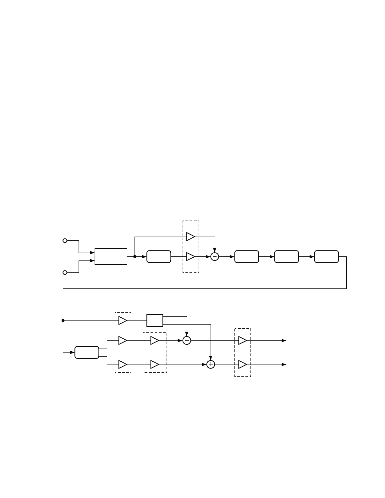
In addition, there is a generic monaural moving delay segment. Its parameters begin with the letters ÒMDÓ. The
moving delay is flexible enough that it can serve as a chorus, flange, or straight delay. For more detailed
information, refer to the section describing the Dual MovDelay and Quad MovDelay algorithms (FXAlgs #715-716).
As implemented in these four algorithms, it can be inserted either before the tone controls (PreDist), or after the
distortion drive (PostDist), or bypassed altogether. This is selected with the MD Insert parameter. Also provided is
the MD Wet/Dry parameter that mixes the output of the moving delay circuit with its own input to be fed into the
next effect in the chain.
L Input
R Input
Chorus
Input Bal
Blend
Ch Wet/Dry
Moving
Delay
Pan
Ch Out Bal
MD Wet/Dry
Tone
Out Gain
Tube
Amp
Cab
Simulator
L Output
R Output
TubeAmp<>MD>Chor with moving delay inserted PreDist
Algorithm Reference-102
Page 10
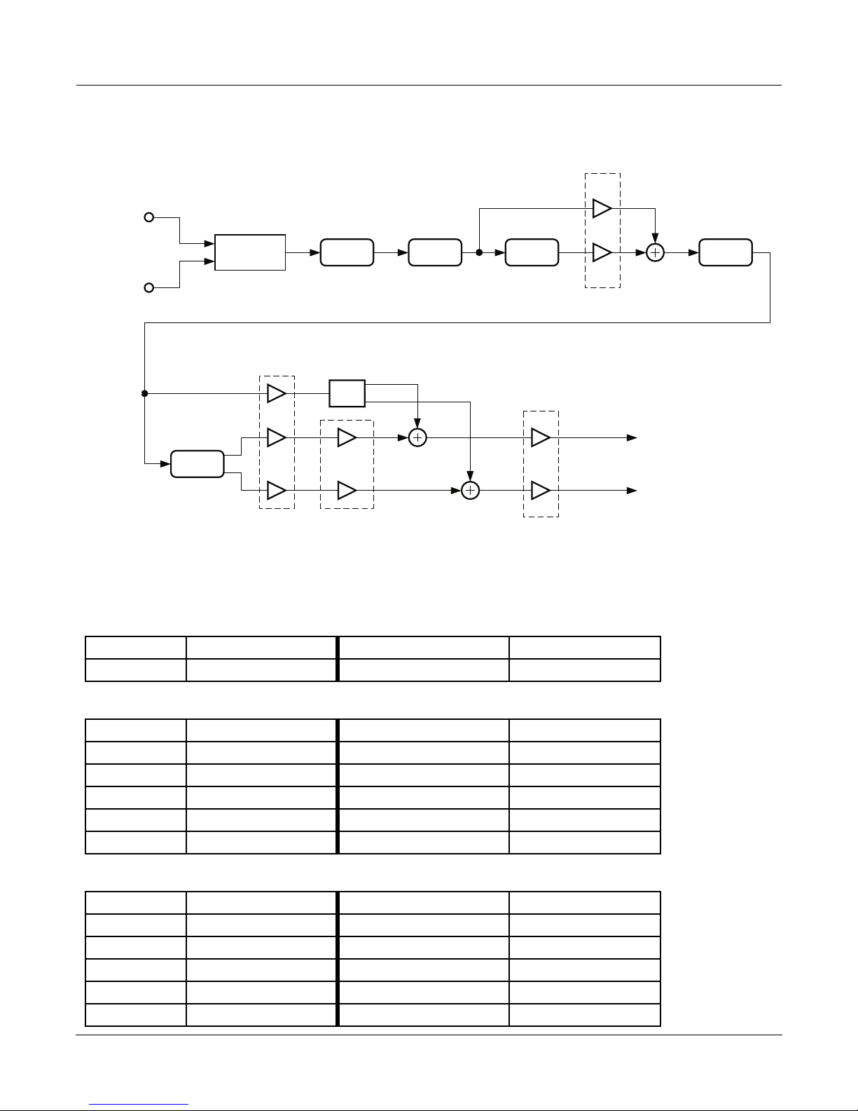
Tube Amp/Distortion/Delay Combinations
MD Wet/Dry
L Input
Input Bal
Blend
Tone
Tube
Amp
Moving
Delay
R Input
Ch Wet/Dry
Pan
Chorus
Ch Out Bal
Out Gain
TubeAmp<>MD>Chor with moving delay inserted PostDist
Parameters:
PAGE 1
In/Out In or Out Out Gain Off; -79.0 to 24.0 dB
Input Bal -100 to 100%
Cab
Simulator
L Output
R Output
PAGE 2 (TubeAmp algs)
Bass Tone 0.0 to 10.0
Mid Tone 0.0 to 10.0 Cab In/Out In or Out
Treb Tone 0.0 to 10.0 Cab Preset Open 12, ...
PAGE 2 (PolyAmp algs)
Bass Tone 0.0 to 10.0
Mid Tone 0.0 to 10.0 Cab In/Out In or Out
Treb Tone 0.0 to 10.0 Cab Preset Open 12, ...
Tube Drive Off; -79.0 to 60.0 dB
Warmth 16 to 25088 Hz
Cab Pan -100 to 100%
Poly Drive 0.0 to 60.0 dB
Warmth 16 to 25088 Hz
Cab Pan -100 to 100%
Algorithm Reference-103
Page 11
Tube Amp/Distortion/Delay Combinations
PAGE 3
MD Insert Post Dist, ... MD Delay 0.0 to 1000.0 ms
MD Wet/Dry 0 to 100% MD LFOMode Flange, ...
MD LFORate 0.00 to 10.00 Hz
MD LFODpth 0.0 to 200.0%
MD Fdbk -100 to 100%
PAGE 4 (Chorus algs)
Ch Rate L 0.01 to 10.00 Hz Ch Rate R 0.01 to 10.00 Hz
Ch Depth L 0.0 to 100.0 cts Ch Depth R 0.0 to 100.0 cts
Ch Delay L 0 to 720 ms Ch Delay R 0 to 720 ms
Ch Fdbk L -100 to 100% Ch Fdbk R -100 to 100%
Ch PtchEnv Triangle or Trapzoid
ChWet/Dry 0 to 100% Ch Out Bal -100 to 100%
PAGE 4 (Flange algs)
Fl Rate 0 to 32 bts Fl Tempo System; 1 to 255 BPM
Fl Xcurs L 0 to 230 ms Fl Xcurs R 0 to 230 ms
Fl Delay L 0 to 230 ms Fl Delay R 0 to 230 ms
Fl Fdbk L -100 to 100% Fl Fdbk R -100 to 100%
Fl Phase L 0 to 360 deg Fl Phase R 0 to 360 deg
Fl Wet/Dry 0 to 100% Fl Out Bal -100 to 100%
In/Out
Toggles the entire effect on or off. When off, the input signal is passed.
Input Bal Adjusts the ratio of left and right algorithm inputs to be summed into the monaural
signal that is processed by the effect. 0% blends equal amount of left and right. Negative
values blend increasing amounts of left, while positive values blend increasing amounts
of right.
Out Gain The overall gain or amplitude at the output of the effect.
Bass Tone, Mid Tone, Treb Tone Adjusts the 3 bands of the tone control integrated with the distortion drive circuit.
Flattest response is obtained by setting Mid Tone to 10.0, and both Bass Tone and Treb
Tone to 0.0.
Tube Drive, Poly Drive Adjusts the gain into each distortion circuit. Higher values produce more distortion.
Warmth Adjusts a 1-pole (6dB/oct) lopass Þlter applied after distortion.
Cab In/Out Turns the cabinet simulator on or off.
Cab Preset Selects the preset cabinet type.
Cab Pan Adjusts the output pan position of the cabinet simulator signal that is mixed at the
output of the algorithm. Note that when Ch Wet/Dry or Fl Wet/Dry is set to 100%, no
signal from the cabinet is mixed directly to the output, so this parameter has no affect.
MD Insert Selects where in the signal chain the moving delay is to be. PreDist places it before the
distortion and tone circuit. PostDist places it between the distortion circuit and cabinet
simulator, and Bypass takes it completely out of the path.
MD Wet/Dry Adjusts the ratio of the moving delay output mixed with its own input to be fed to the
next effect in the chain.
Algorithm Reference-104
Page 12

Tube Amp/Distortion/Delay Combinations
MD Delay Adjusts the delay time for the moving delay circuit, which is the center of LFO
excursion.
MD LFOMode Adjusts the LFO excursion type. In Flange mode, the LFO is optimized for ßange effects
and LFO Dpth adjusts the excursion amount. In ChorTri and ChorTrap modes, the LFO
is optimized for triangle and trapezoidal pitch envelopes respectively, and LFO Dpth
adjusts the amount of chorus detuning. In Delay mode, the LFO is turned off leaving a
basic delay. LFO Rate and LFO Dpth in Delay mode are disabled.
MD LFORate Adjusts the LFO speed for the moving delay circuit.
MD LFODpth In Flange LFO mode, this adjusts an arbitrary LFO excursion amount. In ChorTri and
ChorTrap modes, this controls the chorus detune amount. In delay mode, this is
disabled.
MD Fdbk Adjusts the level of the moving delay circuit output signal fed back into its own input.
Negative values polarity-invert the feedback signal.
Ch Wet/Dry, Fl Wet/Dry Adjusts the ratio of ßange or chorus signal and the cabinet simulator signal fed to
the output of the algorithm. 0% feeds only the cabinet simulator to the output bypassing
the Þnal chorus or ßange. 100% feeds only the ßange or chorus to the output.
Ch Out Bal, Fl Out Bal Adjusts the left/right output balance of the chorus or ßange signal. Negative values
balance toward the left while positive values balance toward the right.
Algorithm Reference-105
Page 13
FXAlg #733: VibChor+Rotor 2 ¥ FXAlg #734: VibChor+Rotor 4
FXAlg #733: VibChor+Rotor 2 ¥
FXAlg #734: VibChor+Rotor 4
Vibrato/chorus, through optional distortion, into rotating speaker
Allocation Units: 2 for VibChor+Rotor 2; 4 for VibChor+Rotor 4
The VibChor+Rotor algorithms contain multiple effects designed for the Hammond B3¨ emulation (KB3 mode).
These effects are the Hammond¨ vibrato/chorus, amplifier distortion, and rotating speaker (Leslie¨). Each of these
effects may be turned off or bypassed, or the entire algorithm may be bypassed.
L Input
R Output
Vibrato/
Chorus
Distortion
(Optional)
Pan
Rotator
Pan
Mic Levels
Pan
Rotator
Pan
Cabinet
Cabinet
L Output
Out Gain
R Output
Block diagram of VibChor+Rotor
The first effect in the chain is the Hammond vibrato/chorus algorithm. The vibrato/chorus has six settings which
are the same as those used in the Hammond B3: three vibrato (V1, V2, V3) and three chorus (C1, C2, C3) settings. In
VibChor+Rotor 4, the vibrato chorus has been carefully modeled after the electro-mechanical vibrato/chorus in the
B3. The vibrato/chorus in VibChor+Rotor 2 uses a conventional design, which has been set to match the B3 sound
as closely as possible, but does not quite have the same character as the VibChor+Rotor 4 vibrato/chorus.
In VibChor+Rotor 4 an amplifier distortion algorithm follows the vibrato/chorus. See the section in this book on
FXAlg #724 for more information about the distortion algorithm.
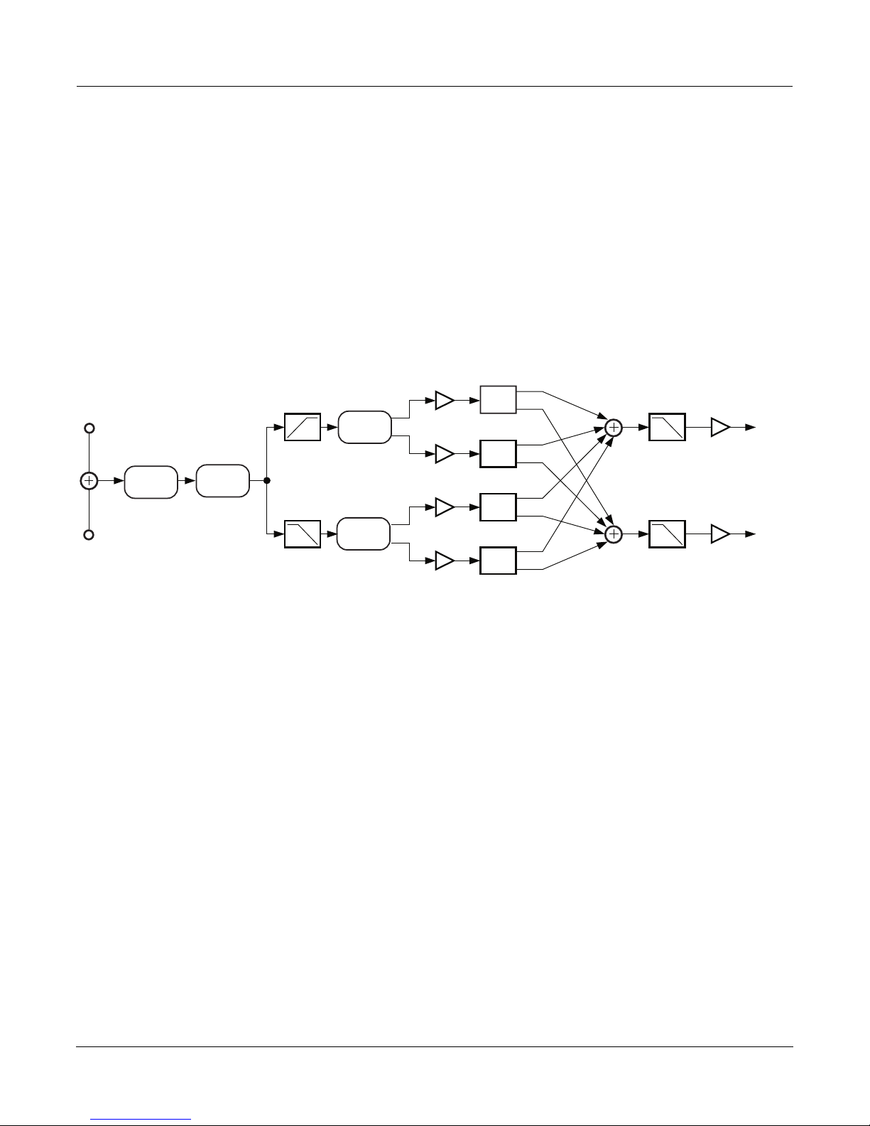
Finally, the signal passes through a rotating speaker routine. The rotating speaker has separately controllable
tweeter and woofer drivers. The signal is split into high and low frequency bands and the two bands are run
through separate rotors. The upper and lower rotors each have a pair of virtual microphones which can be
positioned at varying positions (angles) around the rotors. An angle of 0° is loosely defined as the front. You can
also control the levels and left-right panning of each virtual microphone. The signal is then passed through a final
lowpass filter to simulate the band-limiting effect of the speaker cabinet.
Algorithm Reference-106
Page 14
FXAlg #733: VibChor+Rotor 2 ¥ FXAlg #734: VibChor+Rotor 4
negative anglespositive angles
Rotating speaker with virtual microphones
For the rotating speakers, you can control the crossover frequency of the high and low frequency bands (the
frequency where the high and low frequencies get separated). The rotating speakers for the high and low
frequencies have their own controls. For both, the rotation rate, the effective driver size and tremolo can be set. The
rotation rate sets how fast the rotating speaker is spinning. The effective driver size is the radius of the path followed
by the speaker relative to its center of rotation. This parameter is used to calculate the resulting Doppler shift of the
moving speaker. Doppler shift is the pitch shift that occurs when a sound source moves toward or away from you
the listener. In a rotating speaker, the Doppler shift will sound like vibrato. As well as Doppler shift, there will be
some acoustic shadowing as the speaker is alternately pointed away from you and toward you. The shadowing is
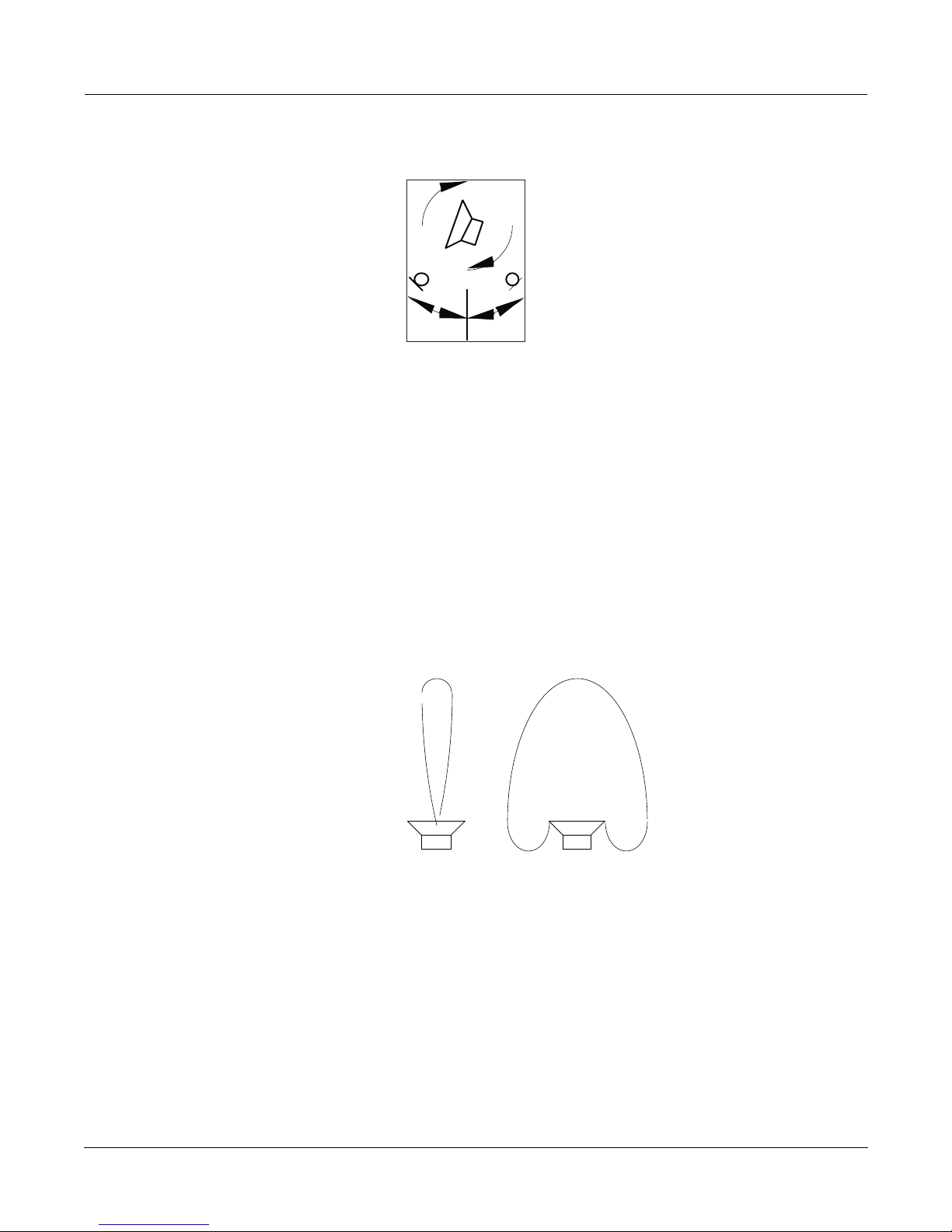
simulated with a tremolo over which you can control the tremolo depth and ÒwidthÓ. The high-frequency driver
(rotating horn) will have a narrower acoustic beam width (dispersion) than the low-frequency driver, and the
widths of both may be adjusted. Note that it can take up to one full speaker rotation before you hear changes to
tremolo when parameter values are changed. Negative microphone angles take a longer time to respond to tremolo
changes than positive microphone angles.
Acoustic beams for (i) low frequency driver and (ii) high frequency driver.
You can control resonant modes within the rotating speaker cabinet with the Lo and Hi Resonate parameters. For
a realistic rotating speaker, the resonance level and delay excursion should be set quite low. High levels will give
wild pitch shifting.
Algorithm Reference-107
(i) (ii)
Page 15
FXAlg #733: VibChor+Rotor 2 ¥ FXAlg #734: VibChor+Rotor 4
Parameters:
PAGE 1
In/Out In or Out Out Gain Off, -79.0 to 24.0 dB
VibChInOut In or Out Dist Drive 0 to 96 dB
Vib/Chor V1 DistWarmth 16 to 25088 Hz
Roto InOut In or Out Cabinet LP 16 to 25088 Hz
PAGE 2
Xover 16 to 25088 Hz
Lo Gain Off, -79.0 to 24.0 dB Hi Gain Off, -79.0 to 24.0 dB
Lo Rate -10.00 to 10.00 Hz Hi Rate -10.00 to 10.00 Hz
Lo Size 0 to 250 mm Hi Size 0 to 250 mm
Lo Trem 0 to 100% Hi Trem 0 to 100%
Lo Beam W 45.0 to 360.0 deg Hi Beam W 45.0 to 360.0 deg
PAGE 3
LoMicA Pos -180.0 to 180.0 deg LoMicB Pos -180.0 to 180.0 deg
LoMicA Lvl 0 to 100% LoMicB Lvl 0 to 100%
LoMicA Pan -100 to 100% LoMicB Pan -100 to 100%
HiMicA Pos -180.0 to 180.0 deg HiMicB Pos -180.0 to 180.0 deg
HiMicA Lvl 0 to 100% HiMicB Lvl 0 to 100%
HiMicA Pan -100 to 100% HiMicB Pan -100 to 100%
PAGE 4
LoResonate 0 to 100% HiResonate 0 to 100%
Lo Res Dly 10 to 2550 samp Hi Res Dly 10 to 2550 samp
LoResXcurs 0 to 510 samp HiResXcurs 0 to 510 samp
ResH/LPhase 0.0 to 360.0 deg
In/Out
When set to ÒInÓ, the algorithm is active; when set to ÒOutÓ the algorithm is bypassed.
Out Gain The overall gain or amplitude at the output of the effect. For distortion, it is often
necessary to turn the output gain down as the distortion drive is turned up.
VibChInOut When set to ÒInÓ the vibrato/chorus is active; when set to ÒOutÓ the vibrato/chorus is
bypassed.
Vib/Chor This control sets the Hammond B3¨ vibrato/chorus. There are six settings for this effect:
three vibratos ÒV1Ó, ÒV2Ó, ÒV3Ó, and three choruses ÒC1Ó, ÒC2Ó, ÒC3Ó
Roto InOut When set to ÒInÓ the rotary speaker is active; when set to ÒOutÓ the rotary speaker is
bypassed.
Dist Drive Applies a boost to the input signal to overdrive the distortion algorithm. When
overdriven, the distortion algorithm will soft-clip the signal. Since distortion drive will
make your signal very loud, you may have to reduce the Out Gain as the drive is
increased. [VibChor+Rotor 4 only]
Algorithm Reference-108
Page 16

FXAlg #733: VibChor+Rotor 2 ¥ FXAlg #734: VibChor+Rotor 4
DistWarmth A lowpass Þlter in the distortion control path. This Þlter may be used to reduce some of
the harshness of some distortion settings without reducing the bandwidth of the signal.
[VibChor+Rotor 4 only]
Cabinet LP A lowpass Þlter to simulate the band-limiting of a speaker cabinet. The Þlter controls the
upper frequency limit of the output.
Xover The frequency at which high and low frequency bands are split and sent to separate
rotating drivers.
Lo Gain The gain or amplitude of the signal passing through the rotating woofer (low-frequency
driver.
Lo Rate The rotation rate of the rotating woofer (low-frequency driver). The woofer can rotate
clockwise or counter-clockwise. The direction of rotation depends on the sign of the rate
parameter. Assuming microphone angles are set toward the front (between -90° and 90°)
and microphones at positive angles are panned to the right (positive pan values), then
positive rates correspond to clockwise rotation when viewed from the top.
Lo Size
The effective size (radius of rotation) of the rotating woofer in millimeters. Affects the
amount of Doppler shift or vibrato of the low frequency signal.
Lo Trem Controls the depth of tremolo of the low frequency signal. Expressed as a percentage of
full scale tremolo.
Lo Beam W The rotating speaker effect attempts to model a rotating woofer for the low frequency
driver. The acoustic radiation pattern of a woofer tends to range from omnidirectional
(radiates in directions in equal amounts) to a wide beam. You may adjust the beam
width from 45° to 360°. If you imagine looking down on the rotating speaker, the beam
angle is the angle between the -6 dB levels of the beam. At 360°, the woofer is
omnidirectional.
Hi Gain The gain or amplitude of the signal passing through the rotating tweeter (high-
frequency driver.
Hi Rate The rotation rate of the rotating tweeter (high-frequency driver). The tweeter can rotate
clockwise or counter-clockwise. The direction of rotation depends on the sign of the rate
parameter. Assuming microphone angles are set toward the front (between -90° and 90°)
and microphones at positive angles are panned to the right (positive pan values), then
positive rates correspond to clockwise rotation when viewed from the top.
Hi Size The effective size (radius of rotation) of the rotating tweeter in millimeters. Affects the
amount of Doppler shift or vibrato of the high frequency signal.
Hi Trem Controls the depth of tremolo of the high frequency signal. Expressed as a percentage of
full scale tremolo.
Hi Beam W The rotating speaker effect attempts to model a rotating horn for the high frequency
driver. The acoustic radiation pattern of a horn tends to be a narrow beam. You may
adjust the beam width from 45° to 360°. If you imagine looking down on the rotating
speaker, the beam angle is the angle between the -6 dB levels of the beam. At 360°, the
horn is omnidirectional (radiates in all directions equally).
Mic Pos The angle of the virtual microphones in degrees from the ÒfrontÓ of the rotating speaker.
This parameter is not well suited to modulation because adjustments to it will result in
large sample skips (audible as clicks when signal is passing through the effect). There are
four of these parameters to include 2 pairs (A and B) for high and low frequency drivers.
Mic Lvl The level of the virtual microphone signal being sent to the output. There are four of
these parameters to include 2 pairs (A and B) for high and low frequency drivers.
Mic Pan Left-right panning of the virtual microphone signals. A setting of -100% is panned fully
left, and 100% is panned fully right. There are four of these parameters to include two
pairs (A and B) for high and low frequency drivers.
Algorithm Reference-109
Page 17

FXAlg #733: VibChor+Rotor 2 ¥ FXAlg #734: VibChor+Rotor 4
LoResonate A simulation of cabinet resonant modes express as a percentage. For realism, you should
use very low settings. This is for the low frequency signal path.
Lo Res Dly The number of samples of delay in the resonator circuit in addition to the rotation
excursion delay. This is for the low frequency signal path.
LoResXcurs The number of samples of delay to sweep through the resonator at the rotation rate of
the rotating speaker. This is for the low frequency signal path.
HiResonate A simulation of cabinet resonant modes expressed as a percentage. For realism, you
should use very low settings. This is for the high frequency signal path.
Hi Res Dly The number of samples of delay in the resonator circuit in addition to the rotation
excursion delay. This is for the high frequency signal path.
HiResXcurs The number of samples of delay to sweep through the resonator at the rotation rate of
the rotating speaker. This is for the high frequency signal path.
ResH/LPhs This parameter sets the relative phases of the high and low resonators. The angle value
in degrees is somewhat arbitrary and you can expect the effect of this parameter to be
rather subtle.
Algorithm Reference-110
Page 18
FXAlg #734: Distort + Rotary
FXAlg #734: Distort + Rotary
Small distortion followed by rotary speaker effect
Allocation Units: 2
Distort + Rotary models an amplifier distortion followed by a rotating speaker. The rotating speaker has separately
controllable tweeter and woofer drivers. The algorithm has three main sections. First, the input stereo signal is
summed to mono and may be distorted by a tube amplifier simulation. The signal is then passed into the rotator
section where it is split into high and low frequency bands and the two bands are run through separate rotators.
The two bands are recombined and measured at two positions, spaced by a controllable relative angle (microphone
simulation) to obtain a stereo signal again. Finally the signal is passed through a speaker cabinet simulation.
L Input
Distortion
R Input
Block diagram of Distort + Rotary
The first part of Distort + Rotary is a distortion algorithm. See the section of this book on FXAlg #723 for details.
Next the signal passes through a rotating speaker routine. See the section of this book on FXAlg #733 for details.
Rotator
L Output
Out GainCabinet
R Output
Rotator
Parameters:
PAGE 1
In/Out In or Out Out Gain Off, -79.0 to 24.0 dB
Cabinet HP 16 to 25088 Hz Dist Drive 0 to 96 dB
Cabinet LP 16 to 25088 Hz DistWarmth 16 to 25088 Hz
PAGE 2
Xover 16 to 25088 Hz Mic Angle 0.0 to 360.0 deg
Lo Gain Off, -79.0 to 24.0 dB Hi Gain Off, -79.0 to 24.0 dB
Lo Rate -10.00 to 10.00 Hz Hi Rate -10.00 to 10.00 Hz
Lo Size 0 to 250 mm Hi Size 0 to 250 mm
Lo Trem 0 to 100% Hi Trem 0 to 100%
PAGE 3
LoResonate 0 to 100% HiResonate 0 to 100%
Lo Res Dly 10 to 2550 samp Hi Res Dly 10 to 2550 samp
LoResXcurs 0 to 510 samp HiResXcurs 0 to 510 samp
Algorithm Reference-111
ResH/LPhs 0.0 to 360.0 deg
Page 19

FXAlg #734: Distort + Rotary
In/Out When set to ÒInÓ, the algorithm is active; when set to ÒOffÓ the algorithm is bypassed.
Out Gain The overall gain or amplitude at the output of the effect. For distortion, it is often
necessary to turn the output gain down as the distortion drive is turned up.
Dist Drive Applies a boost to the input signal to overdrive the distortion algorithm. When
overdriven, the distortion algorithm will soft-clip the signal. Since distortion drive will
make your signal very loud, you may have to reduce the Out Gain as the drive is
increased.
DistWarmth A lowpass Þlter in the distortion control path. This Þlter may be used to reduce some of
the harshness of some distortion settings without reducing the bandwidth of the signal.
Cabinet HP A hipass Þlter to simulate the band-limiting of a speaker cabinet. The Þlter controls the
lower frequency limit of the output.
Cabinet LP A lowpass Þlter to simulate the band-limiting of a speaker cabinet. The Þlter controls the
upper frequency limit of the output.
Xover The frequency at which high and low frequency bands are split and sent to separate
rotating drivers.
For details on the rest of the parameters see the previous section (FXAlg #733) of this book.
Algorithm Reference-112
Page 20
FXAlg #735/6: KB3 FX
FXAlg #735/6: KB3 FX
Vibrato/chorus into distortion into rotating speaker into cabinet
Allocation Units: 7 for full working effect (4 for KB3 FXBus, 3 for KB3 AuxFX)
The KB3 FXBus and KB3 AuxFX algorithms contain multiple effects designed for the Hammond B3 emulation (KB3
mode). For correct operation, both effects must be running at the same time, with the output of KB3 FXBus feeding
the input of KB3 AuxFX. The two algorithms work as one algorithm which use all the available KDFX resources.
While the input to KB3 FXBus is stereo (which gets summed to mono) and the output from KB3 AuxFX is stereo,
the signals between the two algorithms are the low frequency (left) and high frequency (right) signal bands used to
drive the lower and upper rotary speakers. It is possible to run these two algorithms as independent effects, but it
is recommended.
These effects are the Hammond vibrato/chorus, amplifier distortion, and rotating speaker (Leslie) emulations.
Each of these effects may be turned off or bypassed, or the entire algorithm may be bypassed. To bypass the rotary,
the switches in both KB3 FXBus and KB3 AuxFX must be set to ÒOutÓ.
Hi Gain
L Input
R Input
Vibrato/
Chorus
Distortion
Cabinet
Filter
Lo Gain
L Output
R Output
Block diagram of KB3 FXBus
Pan
L Input
R Input
Rotator
Rotator
L Output
Pan
Mic Levels Out Gain
Pan
R Output
Pan
Block diagram of KB3 AuxFX
The first effect in the chain is the Hammond vibrato/chorus algorithm. The vibrato/chorus has six settings which
are the same as those used in the Hammond B3: three vibrato (V1, V2, V3) and three chorus (C1, C2, C3) settings.
The vibrato chorus has been carefully modeled after the electro-mechanical vibrato/chorus in the B3.
An amplifier distortion algorithm follows the vibrato/chorus. For details, see the section in this book on FXAlg
#723.
The distorted signal is next passed to a cabinet emulation filter and a pair of crossover filters for band splitting. The
measurements of a real Leslie¨ speaker was used in the design of these filters. Default parameter values reflect
these measurements, but you may alter them if you like. The Lo HP parameter controls a hipass filter which defines
the lowest frequency to pass through the speaker. Likewise the Hi LP parameter is a lowpass filter controlling the
Algorithm Reference-113
Page 21
FXAlg #735/6: KB3 FX
highest frequency. The crossover filters for the lower and upper drivers may be set independently. A small amount
of overlap seems to work well. The gains of the high and low band signals may also be separately controlled.
At this point KB3 FXBus has finished its processing and passes the high and low signals to the KB3 AuxFX algorithm
which contains the rotating-speaker routine. See the section in this book on FXAlg #733 for details.
Parameters (KB3 FXBus):
PAGE 1
In/Out In or Out Out Gain Off, -79.0 to 24.0 dB
VibChInOut In or Out Dist Drive 0 to 96 dB
Vib/Chor V1 DistWarmth 16 to 25088 Hz
PAGE 2
RotoInOut In or Out
Lo Gain Off, -79.0 to 24.0 dB Hi Gain Off, -79.0 to 24.0 dB
Lo Xover 16 to 25088 Hz Hi Xover 16 to 25088 Hz
Lo HP 16 to 25088 Hz Hi LP 16 to 25088 Hz
In/Out When set to ÒInÓ, the algorithm is active; when set to ÒOutÓ the algorithm is bypassed.
For the entire algorithm to be active, KB3 AuxFX must also be active.
Out Gain The overall gain or amplitude at the output of the effect. For distortion, it is often
necessary to turn the output gain down as the distortion drive is turned up.
VibChInOut When set to ÒInÓ the vibrato/chorus is active; when set to ÒOutÓ the vibrato/chorus is
bypassed.
Vib/Chor This control sets the Hammond B3¨ vibrato/chorus. There are six settings for this effect:
three vibratos ÒV1Ó, ÒV2Ó, ÒV3Ó, and three choruses ÒC1Ó, ÒC2Ó, ÒC3Ó
Roto InOut When set to ÒInÓ the rotary speaker is active; when set to ÒOutÓ the rotary speaker is
bypassed. By bypassing the rotary effect in KB3 FXBus, only the crossover Þlters are
bypassed. You must also bypass KB3 AuxFX to completely bypass the rotary speakers.
Likewise, for the entire rotary to be active, KB3 AuxFX must also be active.
Dist Drive Applies a boost to the input signal to overdrive the distortion algorithm. When
overdriven, the distortion algorithm will soft-clip the signal. Since distortion drive will
make your signal very loud, you may have to reduce the Out Gain as the drive is
increased.
Warmth A lowpass Þlter in the distortion control path. This Þlter may be used to reduce some of
the harshness of some distortion settings without reducing the bandwidth of the signal.
Lo Gain The gain or amplitude of the signal passing through the rotating woofer (low frequency
driver. The control is also available in KB3 AuxFX.
Lo Xover The crossover frequency for the low frequency driver. Lo Xover controls a lowpass Þlter.
Lo HP A hipass Þlter to simulate the band-limiting of a speaker cabinet. The Þlter controls the
lower frequency limit of the output.
Hi Gain The gain or amplitude of the signal passing through the rotating tweeter (high frequency
driver. The control is also available in KB3 AuxFX.
Hi Xover The crossover frequency for the high frequency driver. Hi Xover controls a hipass Þlter.
Hi LP A lowpass Þlter to simulate the band-limiting of a speaker cabinet. The Þlter controls the
upper frequency limit of the output.
Algorithm Reference-114
Page 22
Parameters (KB3 AuxFX):
PAGE 1
In/Out In or Out Out Gain Off, -79.0 to 24.0 dB
PAGE 2
Lo Gain Off, -79.0 to 24.0 dB Hi Gain Off, -79.0 to 24.0 dB
Lo Rate -10.00 to 10.00 Hz Hi Rate -10.00 to 10.00 Hz
Lo Size 0 to 250 mm Hi Size 0 to 250 mm
Lo Trem 0 to 100% Hi Trem 0 to 100%
Lo Beam W 45.0 to 360.0 deg Hi Beam W 45.0 to 360.0 deg
PAGE 3
LoMicA Pos -180.0 to 180.0 deg LoMicB Pos -180.0 to 180.0 deg
LoMicA Lvl 0 to 100% LoMicB Lvl 0 to 100%
LoMicA Pan -100 to 100% LoMicB Pan -100 to 100%
HiMicA Pos -180.0 to 180.0 deg HiMicB Pos -180.0 to 180.0 deg
HiMicA Lvl 0 to 100% HiMicB Lvl 0 to 100%
HiMicA Pan -100 to 100% HiMicB Pan -100 to 100%
FXAlg #735/6: KB3 FX
PAGE 4
LoResonate 0 to 100% HiResonate 0 to 100%
Lo Res Dly 10 to 2550 samp Hi Res Dly 10 to 2550 samp
LoResXcurs 0 to 510 samp HiResXcurs 0 to 510 samp
ResH/LPhs 0.0 to 360.0 deg
In/Out When set to ÒInÓ, the algorithm is active; when set to ÒOffÓ the algorithm is bypassed.
For the entire algorithm to be active, KB3 FXBus must also be active with its Roto InOut
parameter set to ÒInÓ. To completely bypass the rotary, one or both of the In/Out or Roto
InOut parameters in KB3 FXBus must also be bypassed.
Out Gain The overall gain or amplitude at the output of the effect.
Lo Gain The gain or amplitude of the signal passing through the rotating woofer (low frequency
driver. The control is also available in KB3 FXBus.
Hi Gain The gain or amplitude of the signal passing through the rotating tweeter (high frequency
driver. The control is also available in KB3 FXBus.
For details on the rest of the parameters see the section of this book on FXAlg #733.
Algorithm Reference-115
Page 23
FXAlg #900: Env Follow Filt
FXAlg #900: Env Follow Filt
Envelope-following stereo 2-pole resonant filter
Allocation Units: 2
The envelope-following filter is a stereo resonant filter with the resonant frequency controlled by the envelope of
the input signal (the maximum of left or right). The filter type is selectable and may be one of low pass (i), highpass
(ii), band pass (iii), or notch (iv).
(i) (ii)
(iii) (iv)
Resonant Filter Types: (i) lowpass, (ii) highpass, (iii) bandpass, and (iv) notch.
The resonant frequency of the filter will remain at the minimum frequency (Min Freq) as long as the signal envelope
is below the Threshold. The Freq Sweep parameter controls how much the frequency will change with changes in
envelope amplitude. The frequency range is 0 to 8372 Hz, though the minimum setting for Min Freq is 16 Hz. Note
that the term minimum frequency is a reference to the resonant frequency at the minimum envelope level; with a
negative Freq Sweep, the filter frequency will sweep below the Min Freq. A meter is provided to show the current
resonance frequency of the filter.
Envelope
Follower
L Input
L Input
Resonant Filter
R Input
Block diagram of envelope-following filter
The filter Resonance level may be adjusted. The resonance is expressed in decibels (dB) of gain at the resonant
frequency. Since 50 dB of gain is available, you will have to be careful with your gain stages to avoid clipping.
R Input
Algorithm Reference-116
Page 24
FXAlg #900: Env Follow Filt
The attack and release rates of the envelope follower are adjustable. The rates are expressed in decibels per second
(dB/s). The envelope may be smoothed by a lopass filter which can extend the attack and release times of the
envelope follower. A level meter with a threshold marker is provided.
Parameters:
PAGE 1
Wet/Dry 0 to 100%wet Out Gain Off, -79.0 to 24.0 dB
FilterType Lowpass Min Freq 16 to 8372 Hz
F Freq Sweep -100 to 100%
0Hz 2k 4k 6k Resonance 0 to 50 dB
PAGE 2
Threshold -79.0 to 0.0 dB Atk Rate 0.0 to 300.0 dB/s
Rel Rate 0.0 to 300.0 dB/s
Smth Rate 0.0 to 300.0 dB/s
E
-dB 60 40 * 16 * 8 4 0
Wet/Dry The amount of modulated (wet) signal relative to unaffected (dry) signal as a percent.
Out Gain The overall gain or amplitude at the output of the effect.
FilterType The type of resonant Þlter to be used. May be one of ÒLowpassÓ, ÒHighpassÓ,
ÒBandpassÓ, or ÒNotchÓ.
Min Freq The base frequency of the resonant Þlter. The Þlter resonant frequency is set to the Min
Freq while the signal envelope is at its minimum level or below the threshold.
Freq Sweep How far the Þlter frequency can change from the Min Freq setting as the envelope
amplitude changes. Freq Sweep may be positive or negative so the Þlter frequency can
rise above or fall below the Min Freq setting.
Resonance The resonance level of the resonant Þlter. Resonance sets the level of the resonant peak.
In the notch Þlter, this sets the amount of cut, so 0 dB provides the highest, widest notch,
and higher levels make the notch increasingly narrower and shallower.
Threshold Represents the level above which signal envelope must rise before the Þlter begins to
follow the envelope. Below the threshold, the Þlter resonant frequency will remain at the
Min frequency.
Atk Rate Adjusts the upward slew rate of the envelope detector.
Rel Rate Adjusts the downward slew rate of the envelope detector.
Smth Rate Smooths the output of the envelope follower. Smoothing slows down the envelope
follower and can dominate the attack and release rates if set to a lower rate than either of
these parameters.
Algorithm Reference-117
Page 25
FXAlg #901: TrigEnvelopeFilt
FXAlg #901: TrigEnvelopeFilt
Triggered envelope-following stereo 2-pole resonant filter
Allocation Units: 2
The triggered envelope-following filter is used to produce a filter sweep when the input rises above a trigger level.
The triggered envelope-following filter is a stereo resonant filter with the resonant frequency controlled by a
triggered envelope follower. The filter type is selectable and may be one of low pass (i), high pass (ii), band pass
(iii), or notch (iv). See the previous section of this book, FXAlg #900, for diagrams of the filter actions.
Envelope
Follower
L Input
R Input
Block diagram of Triggered Envelope Filter
The resonant frequency of the filter will remain at the minimum frequency (Min Freq) prior to being triggered. On
a trigger, the resonant frequency will sweep to the maximum frequency (Max Freq). The minimum and maximum
frequencies may be set to any combination of frequencies between 16 and 8372 Hz. Note that the terms minimum
and maximum frequency are a reference to the resonant frequencies at the minimum and maximum envelope
levels; you may set either of the frequencies to be larger than the other. A meter is provided to show the current
resonance frequency of the filter.
The filter Resonance level may be adjusted. The resonance is expressed in decibels (dB) of gain at the resonant
frequency. Since 50 dB of gain is available, you will have to be careful with your gain stages to avoid clipping.
When the input signal envelope rises above the trigger level, an envelope generator is started which has an instant
attack and exponential decay. The generated attack may be lengthened with the smoothing parameter. The
smoothing parameter can also lengthen the generated decay if the smoothing rate is lower than the decay. The
generated envelope is then used to control the resonant frequency of the filter.
Trigger
Generator
Triggered
Envelope
Generator
L Input
Resonant Filter
R Input
The time constant of the envelope follower may be set (Env Rate) as well as the decay rate of the generated envelope
(Rel Rate). After the detected envelope rises above the Trigger level, a trigger event cannot occur again until the
signal drops below the Retrigger level. In general, Retrigger should be set lower than the Trigger level. A level meter
with a trigger marker is provided.
Parameters:
PAGE 1
Wet/Dry 0 to 100%wet Out Gain Off, -79.0 to 24.0 dB
FilterType Lowpass Min Freq 16 to 8372 Hz
F Max Freq 16 to 8372 Hz
0Hz 2k 4k 6k Resonance 0 to 50 dB
Algorithm Reference-118
Page 26
FXAlg #901: TrigEnvelopeFilt
PAGE 2
Trigger -79.0 to 0.0 dB Env Rate 0.0 to 300.0 dB/s
Retrigger -79.0 to 0.0 dB Rel Rate 0.0 to 300.0 dB/s
Smth Rate 0.0 to 300.0 dB/s
E
-dB 60 40 * 16 * 8 4 0
Wet/Dry The amount of modulated (wet) signal relative to unaffected (dry) signal as a percent.
Out Gain The overall gain or amplitude at the output of the effect.
FilterType The type of resonant Þlter to be used. May be one of ÒLowpassÓ, ÒHighpassÓ,
ÒBandpassÓ, or ÒNotchÓ.
Min Freq The base frequency of the resonant Þlter. The Þlter resonant frequency is set to the base
frequency while the signal envelope is below the threshold.
Max Freq The frequency of the resonant Þlter that can be reached when the envelope follower
output reaches full-scale. The resonant frequency will sweep with the envelope from the
base frequency, approaching the limit frequency with rising amplitudes.
Resonance The resonance level of the resonant Þlter. Resonance sets the level of the resonant peak.
In the notch Þlter, this sets the amount of cut, so 0 dB provides the highest, widest notch,
and higher levels make the notch increasingly narrower and shallower.
Trigger The threshold at which the envelope detector triggers in fractions of full scale where 0dB
is full scale.
Retrigger The threshold at which the envelope detector resets such that it can trigger again in
fractions of full scale where 0dB is full scale. This value is only useful when it is below
the value of Trigger.
Env Rate The envelope detector decay rate which can be used to prevent false triggering. When
the signal envelope falls below the retrigger level, the Þlter can be triggered again when
the signal rises above the trigger level. Since the input signal can ßuctuate rapidly, it is
necessary to adjust the rate at which the signal envelope can fall to the retrigger level.
The rate is provided in decibels per second (dB/s).
Rel Rate The downward slew rate of the triggered envelope generator. The rate is provided in
decibels per second (dB/s).
Smth Rate Smooths the output of the envelope generator. Smoothing slows down the envelope
follower and can dominate the release rate if set lower rate than this parameter. You can
use the smoothing rate to lengthen the attack of the generated envelope which would
otherwise have an instant attack. The rate is provided in decibels per second (dB/s)
Algorithm Reference-119
Page 27
FXAlg #902: LFO Sweep Filter
FXAlg #902: LFO Sweep Filter
LFO-following stereo 2-pole resonant filter
Allocation Units: 2
The LFO following filter is a stereo resonant filter with the resonant frequency controlled by an LFO (low-frequency
oscillator). The filter type is selectable and may be one of low pass (i), high pass (ii), band pass (iii), or notch (iv). See
the section of this book on FXAlg #900 for diagrams of the filter actions.
The resonant frequency of the filter will sweep between the minimum frequency (Min Freq) and the maximum
frequency (Max Freq). The minimum and maximum frequencies may be set to any combination of frequencies
between 16 and 8372 Hz. Note that the terms minimum and maximum frequency are a reference to the resonant
frequencies at the minimum and maximum envelope levels; you may set either of the frequencies to be larger than
the other, though doing so will just invert the direction of the LFO. Meters are provided to show the current
resonance frequencies of the left and right channel filters.
The filter Resonance level may be adjusted. The resonance is expressed in decibels (dB) of gain at the resonant
frequency. Since 50 dB of gain is available, you will have to be careful with your gain stages to avoid clipping.
You can set the frequency of the LFO using the LFO Tempo and LFO Period controls. You can explicitly set the
tempo or use the system tempo from the sequencer (or MIDI clock). The LFO Period control sets the period of the
LFO (the time for one complete oscillation) in terms of the number of tempo beats per LFO period.
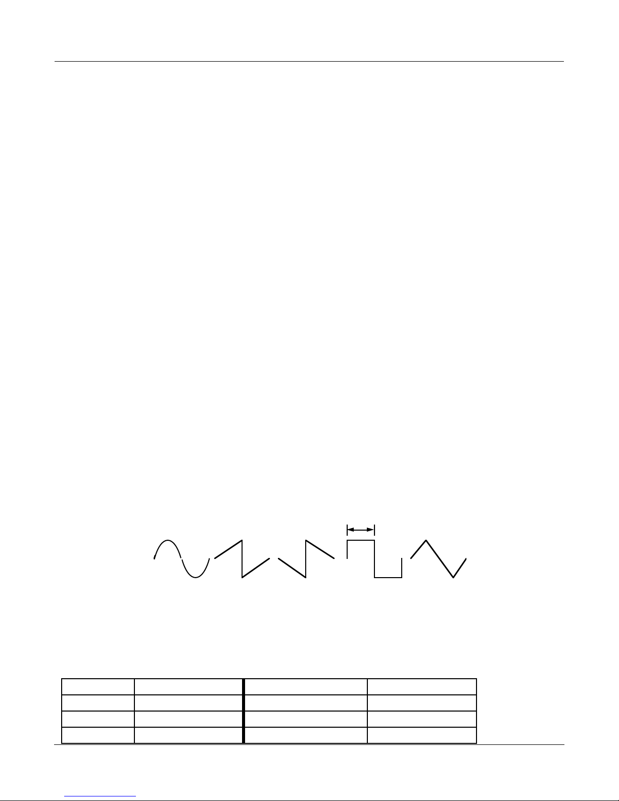
The LFO may be configured to one of a variety of wave shapes. Available shapes are Sine, Saw+, Saw-, Pulse and
Tri. Sine is simply a sinusoid waveform. Tri produces a triangular waveform, and Pulse produces a series of square
pulses where the pulse width can be adjusted with the ÒLFO PlsWidÓ parameter. When pulse width is 50%, the
signal is a square wave. The ÒLFO PlsWidÓ parameter is only active when the Pulse waveform is selected. Saw+ and
Saw- produce rising and falling sawtooth waveforms. The Pulse and Saw waveforms have abrupt, discontinuous
changes in amplitude which can be smoothed. The pulse wave is implemented as a hard clipped sine wave, and, at
50% width, it turns into a sine wave when set to 100% smoothing. The sudden change in amplitude of the sawtooths
develops a more gradual slope with smoothing, ending up as triangle waves when set to 100% smoothing.
PulseWidth
Sine Saw+ Saw- Pulse Tri
Configurable Wave Shapes
Parameters:
PAGE 1
Wet/Dry 0 to 100%wet Out Gain Off, -79.0 to 24.0 dB
LFO Tempo System, 1 to 255 BPM LFO Shape Sine
LFO Period 1/24 to 32 bts LFO PlsWid 0 to 100%
Algorithm Reference-120
LFO Smooth 0 to 100%
Page 28

FXAlg #902: LFO Sweep Filter
PAGE 2
FilterType Lowpass Min Freq 16 to 8372 Hz
Max Freq 16 to 8372 Hz
Resonance 0 to 50 dB
L Phase 0.0 to 360.0 deg R Phase 0.0 to 360.0 deg
L R
0Hz 2k 4k 6k 0Hz 2k 4k 6k
Wet/Dry The amount of modulated (wet) signal relative to unaffected (dry) signal as a percent.
Out Gain The overall gain or amplitude at the output of the effect.
LFO Tempo Basis for the rates of the LFO, as referenced to a musical tempo in bpm (beats per
minute). When this parameter is set to ÒSystemÓ, the tempo is locked to the internal
sequencer tempo or to incoming MIDI clocks. When it is set to ÒSystemÓ, sources (FUNs,
LFOs, ASRs etc.) will have no effect on the Tempo parameter.
LFO Period
Sets the LFO rate based on the Tempo determined above: the number of beats
corresponding to one period of the LFO cycle. For example, if the LFO Period is set to
Ò4Ó, the LFOs will take four beats to pass through one oscillation, so the LFO rate will be
1/4th of the Tempo setting. If it is set to Ò6/24Ó (=1/4), the LFO will oscillate four times
as fast as the Tempo. At Ò0Ó, the LFOs stop oscillating and their phase is undetermined
(wherever they stopped).
LFO Shape The waveform type for the LFO. Choices are Sine, Saw+, Saw-, Pulse, and Tri.
LFO PlsWid When the LFO Shape is set to Pulse, the PlsWid parameter sets the pulse width as a
percentage of the waveform period. The pulse is a square wave when the width is set to
50%. This parameter is active only when the Pulse waveform is selected.
LFO Smooth Smooths the Saw+, Saw-, and Pulse waveforms. For the sawtooth waves, smoothing
makes the waveform more like a triangle wave. For the Pulse wave, smoothing makes
the waveform more like a sine wave.
FilterType The type of resonant Þlter to be used. May be one of ÒLowpassÓ, ÒHighpassÓ,
ÒBandpassÓ, or ÒNotchÓ.
Min Freq The minimum frequency of the resonant Þlter. This is the resonant frequency at one of
the extremes of the LFO sweep. The resonant Þlter frequency will sweep between the
Min Freq and Max Freq.
Max Freq The maximum frequency of the resonant Þlter. This is resonant frequency at the other
extreme of the LFO sweep. The resonant Þlter frequency will sweep between the Min
Freq and Max Freq.
Resonance The resonance level of the resonant Þlter. Resonance sets the level of the resonant peak.
In the notch Þlter, this sets the amount of cut, so 0 dB provides the highest, widest notch,
and higher levels make the notch increasingly narrower and shallower.
L Phase The phase angle of the left channel LFO relative to the system tempo clock and the right
channel phase.
R Phase The phase angle of the right channel LFO relative to the system tempo clock and the left
channel phase.
Algorithm Reference-121
Page 29

FXAlg #903 Resonant Filter ¥ FXAlg #904 Dual Res Filter
FXAlg #903 Resonant Filter ¥
FXAlg #904 Dual Res Filter
Stereo and dual-mono 2-pole resonant filters
Allocation Units: 1 (each)
The resonant filter is available as a stereo (linked parameters for left and right) or dual mono (independent controls
for left and right). The filter type is selectable and may be one of low pass (i), high pass (ii), band pass (iii), or notch
(iv). See the section of this book on FXAlg #900 for diagrams of the filter actions.
The resonant frequency of the filter and the filter resonance level may be adjusted.
Parameters (Resonant Filter):
PAGE 1
Wet/Dry 0 to 100%wet Out Gain Off, -79.0 to 24.0 dB
FilterType Lowpass
Frequency 16 to 8372 Hz
Resonance 0 to 50 dB
Parameters (Dual Res Filter):
PAGE 1
L Wet/Dry 0 to 100%wet R Wet/Dry 0 to 100%wet
L Output Off, -79.0 to 24.0 dB R Output Off, -79.0 to 24.0 dB
PAGE 2
L FiltType Lowpass R FiltType Highpass
L Freq 16 to 8372 Hz R Freq 16 to 8372 Hz
LResonance 0 to 50 dB RResonance 0 to 50 dB
Wet/Dry The amount of Þltered (wet) signal relative to unaffected (dry) signal.
Out Gain The overall gain or amplitude at the output of the Þlter.
FilterType The type of resonant Þlter to be used. May be one of ÒLowpassÓ, ÒHighpassÓ,
ÒBandpassÓ, or ÒNotchÓ.
Frequency The frequency of the resonant Þlter peak (or notch) in Hz. The frequencies correspond to
semitone increments.
Resonance The resonance level of the resonant Þlter. Resonance sets the level of the resonant peak.
In the notch Þlter, this sets the amount of cut, so 0 dB provides the highest, widest notch,
and higher levels make the notch increasingly narrower and shallower.
Algorithm Reference-122
Page 30

FXAlg #905: EQ Morpher ¥ FXAlg #906: Mono EQ Morpher
FXAlg #905: EQ Morpher ¥
FXAlg #906: Mono EQ Morpher
Parallel resonant bandpass filters with parameter morphing
Allocation Units: 4 for EQ Morpher, 2 for Mono EQ Morpher
The EQ Morpher algorithms have four parallel bandpass filters acting on the input signal, whose results are
summed for the final output. EQ Morpher is a stereo algorithm for which the left and right channels receive separate
processing using the same linked controls. Mono EQ Morpher sums the input left and right channels into a mono
signal, so there is only one channel of processing. Both algorithms have output panning. In EQ Morpher, a stereo
panner like that on the KDFX Studio INPUT pages is used, which includes a width parameter to control the width
of the stereo field. Mono EQ Morph uses a standard mono panner for positioning the mono signal between the left
and right speakers.
EQ Gain
#1
L Input
R Input
Mono EQ Morpher (EQ Morpher is similar)
For each filter, there are two sets of parameters, A and B. The parameter Morph A>B determines which parameter
set is active. When Morph A>B is set to 0%, you are hearing the A parameters; when set to 100%, you are hearing
the B parameters. The filters may be gradually moved from A to B and back again by moving the Morph A>B
parameter between 0 and 100%.
#2
#3
#4
EQ Gain
Out Gain
Pan
EQ Gain
EQ Gain
In/Out
L Output
R Output
The four filters are parametric bandpass filters. These are not the usual parametric filters you are familiar with.
Normal parametric filters boost or cut the signal at the frequency you specify relative to the signal at other
frequencies. The bandpass filters used here pass only signals at the frequency you specify and cut all other
frequencies. The gain controls set the levels of each filterÕs output. Like the normal parametric filters, you have
control of the filtersÕ frequencies and bandwidths. The Freq Scale parameters may be used to adjust the A or B filtersÕ
frequencies as a group. This allows you to maintain a constant spectral relationship between your filters while
adjusting the frequencies up and down. The filters are arranged in parallel and their outputs summed, so the
bandpass peaks are added together and the multiple resonances are audible.
Algorithm Reference-123
Page 31

FXAlg #905: EQ Morpher ¥ FXAlg #906: Mono EQ Morpher
0 dB
p
m
A
-10
-20
-30
Bandwidth
Freq
0 dB
-10
-20
-30
Freq
(i) (ii)
Frequency response of (i) a single bandpass filter, and (ii) the sum of two bandpass filters
Now that weÕve gone through what the algorithm does, the question becomes ÒWhy are we doing this?Ó With
careful thought to parameter settings, EQ Morph does an excellent job of simulating the resonances of the vocal
tract. A buzz or sawtooth signal is a good choice of source material to experiment with the EQ Morphers. Set the
Morph A>B parameter to 0%, and find a combination of A filter settings which give an interesting vowel like sound.
It may help to start from existing ROM presets. Next set Morph A>B to 100% and set the B parameters to a different
vowel-like sound. You can now set up some FXMods on Morph A>B to morph between the two sets of parameters,
perhaps using Freq Scale to make it more expressive.
When morphing from the A parameters to the B parameters, A filter #1 moves to B filter #1, A filter #2 moves to B
filter #2, and so on. For the most normal and predictable results, itÕs a good idea not to let the frequencies of the
filters cross each other during the morphing. You can ensure this doesnÕt happen by making sure the four filters
are arranged in ascending order of frequencies. Descending order is okay too, provided you choose an order and
stick to it.
Parameters:
PAGE 1
In/Out In or Out Out Gain Off, -79.0 to 24.0 dB
Morph A>B 0 to 100% Out Pan -100 to 100%
Out Width* -100 to 100%
AFreqScale -8600 to 8600 ct BFreqScale -8600 to 8600 ct
*EQ Morpher only, not Mono EQ Morpher.
PAGE 2
A Freq 1 16 to 25088 Hz B Freq 1 16 to 25088 Hz
A Width 1 0.010 to 5.000 oct B Width 1 0.010 to 5.000 oct
A Gain 1 -79.0 to 24.0 dB B Gain 1 -79.0 to 24.0 dB
A Freq 2 16 to 25088 Hz B Freq 2 16 to 25088 Hz
A Width 2 0.010 to 5.000 oct B Width 2 0.010 to 5.000 oct
A Gain 2 -79.0 to 24.0 dB B Gain 2 -79.0 to 24.0 dB
Algorithm Reference-124
Page 32

FXAlg #905: EQ Morpher ¥ FXAlg #906: Mono EQ Morpher
PAGE 3
A Freq 3 16 to 25088 Hz B Freq 3 16 to 25088 Hz
A Width 3 0.010 to 5.000 oct B Width 3 0.010 to 5.000 oct
A Gain 3 -79.0 to 24.0 dB B Gain 3 -79.0 to 24.0 dB
A Freq 4 16 to 25088 Hz B Freq 4 16 to 25088 Hz
A Width 4 0.010 to 5.000 oct B Width 4 0.010 to 5.000 oct
A Gain 4 -79.0 to 24.0 dB B Gain 4 -79.0 to 24.0 dB
In/Out When set to ÒInÓ the algorithm is active; when set to ÒOutÓ the algorithm is bypassed.
Out Gain An overall level control of the EQ Morpher output.
Out Pan Provides panning of the output signal between left and right output channels. A setting
of -100% is panned left and 100% is panned right. For EQ Morph, this is a stereo panner
which pans the entire stereo image, the same way the input sends on a KDFX INPUT
page are handled, when set to the ÒSPÓ mode.
idth The width of the stereo Þeld is controlled by this parameter. A setting of 100% is the
Out W
same full width as the input signal. At 0% the left and right channels are narrowed to the
point of being mono. Negative values reverse the left and right channels. [EQ Morpher
only]
Morph A>B When set to 0% the ÒAÓ parameters are controlling the Þlters, and when set to 100%, the
ÒBÓ parameters control the Þlters. Between 0 and 100%, the Þlters are at interpolated
positions. When morphing from A to B settings, the A Þlter #1 will change to the B Þlter
#1, A Þlter #2 moves to B Þlter #2, and so on. This is an excellent candidate for
assignment to a real-time KDFX Modulation.
FreqScale The Þlter frequencies for the A and B parameter sets may be offset with the FreqScale
parameters. After setting the Þlter parameters, the FreqScale parameters will move each
of the four Þlter frequencies together by the same relative pitch.This, too, is an excellent
candidate for assignment to a real-time KDFX Modulation.
For the two Þlter sets A & B, there are four Þlters 1, 2, 3 and 4:
Freq The center frequency of the bandpass Þlter peak in Hz. This frequency may be offset by
the FreqScale parameter.
Width The bandwidth of the bandpass Þlter in octaves. Narrow bandwidths provide the most
convincing vocal sounds.
Gain The level of the bandpass Þlter output. At 0 dB, a sine wave at the same frequency as the
Þlter will be neither boosted nor cut. At settings greater than 0 dB, the (hypothetical) sine
wave is boosted, and below 0 dB the sine wave is cut. Signals at frequencies other than
the Þlter frequency are always cut more than a signal at the Þlter frequency. The amount
that other frequencies are cut depends on the bandwidth of the bandpass Þlter.
Algorithm Reference-125
Page 33

FXAlg #907: Ring Modulator
FXAlg #907: Ring Modulator
A configurable ring modulator
Allocation Units: 1
Ring modulation is a simple effect in which two signals are multiplied together. Typically, an input signal is
modulated with a simple carrier waveform such as a sine wave or a sawtooth. Since the modulation is symmetric
(a*b = b*a), deciding which signal is the carrier and which is the modulation signal is a question of perspective. A
simple, unchanging waveform is generally considered the carrier.
To see how the ring modulator works, weÕll have to go through a little high school math and trigonometry. If you
like, you can skip the howÕs and whyÕs and go straight to the discussion of controlling the algorithm.
LetÕs look at the simple case of two equal amplitude sine waves modulating each other. Real signals will be more
complex, but they will be much more difficult to analyze. The two sine waves generally will be oscillating at
different frequencies. A sine wave signal at any time t having a frequency f is represented as sin(ft + f) where f is
constant phase angle to correct for the sine wave not being 0 at t = 0. The sine wave could also be represented with
a cosine function which is a sine function with a 90° phase shift. To simply matters, we will write A = f1t + f1 for one
of the sine waves and B = f2t + f2 for the other sine wave. The ring modulator multiplies the two signals to produce
sin A sin B. We can try to find a trigometric identity for this, or we can just look up in a trigonometry book,
2 sin A sin B = cos(A - B) - cos(A + B).
This equation tells us that multiplying two sine waves produces two new sine waves (or cosine waves) at the sum
and difference of the original frequencies. The following figure shows the output frequencies (solid lines) for a given
input signal pair (dashed lines):
Magnitude
A B A+BB-A
Result of Modulating Two Sine Waves, A and B
This algorithm has two operating modes, set with the Mod Mode parameter. In ÒL*RÓ mode, you supply the
modulation and carrier signals as two mono signals on the left and right inputs. The output in ÒL*RÓ mode is also
mono and you may use the L*R Pan parameter to pan the output. The oscillator parameters on parameter pages 2
and 3 will be inactive while in ÒL*RÓ mode. The following figure shows the signal flow when in ÒL*RÓ mode:
Frequency
Algorithm Reference-126
Page 34

Dry
FXAlg #907: Ring Modulator
L Input
Out Gain
L Output
Pan
R Input
Wet
R Output
Ring Modulator in ÒL*RÓ Mode
The other modulation mode is ÒOscÓ. In this mode, the algorithm inputs and outputs are stereo, and the carrier
signal for both channels is generated inside the algorithm.
Dry
L Input
R Input
Osc1 + Sine2 + Sine3 + Sine4 + Sine5
Wet
Out Gain
Wet
L Output
R Output
The carrier signal is the sum of five oscillators. On all of the oscillators, level and frequency may be set. Four of the
oscillators are simple sine waves, while the fifth may be configured to one of a variety of wave shapes. Available
shapes are Sine, Saw+, Saw-, Pulse, Tri and Expon. Sine is simply another sine waveform. Tri produces a triangular
waveform, and Expon produces a waveform with narrow, sharp peaks which seems to rise exponentially from 0.
Pulse produces a series of square pulses where the pulse width can be adjusted with the ÒOsc1PlsWidÓ parameter.
When pulse width is 50%, the signal is a square wave. The ÒOsc1PlsWidÓ parameter is only active when the Pulse
waveform is selected. Saw+ and Saw- produce rising and falling sawtooth waveforms.
Smoothing is available to reduce the upper partials of the Pulse and Saw waveforms. The pulse wave, at 50% width,
turns into a sine wave when set to 100% smoothing. The sudden change in amplitude of a sawtooth turns into a
more gradual slope with smoothing, ending up as a triangle wave when set to 100% smoothing.
Algorithm Reference-127
Dry
Ring Modulator in ÒOscÓ Mode
Page 35

FXAlg #907: Ring Modulator
e
PulseWidth
Sine Saw+ Saw- Puls
Tri Expon
Configurable Wave Shapes (Osc1 only)
Parameters:
PAGE 1
Wet/Dry 0 to 100%wet Out Gain Off, -79.0 to 24.0 dB
Mod Mode L*R or Osc L*R Gain Off, -79.0 to 48.0 dB
L*R Pan -100 to 100%
PAGE 2
Osc1 Lvl 0 to 100% Osc1 Freq 16 to 25088 Hz
Osc1 Shape Sine
Osc1PlsWid 0 to 100%
Osc1Smooth 0 to 100%
PAGE 3
Sine2 Lvl 0 to 100% Sine2 Freq 16 to 25088 Hz
Sine3 Lvl 0 to 100% Sine3 Freq 16 to 25088 Hz
Sine4 Lvl 0 to 100% Sine4 Freq 16 to 25088 Hz
Sine5 Lvl 0 to 100% Sine5 Freq 16 to 25088 Hz
Wet/Dry The amount of modulated (wet) signal relative to unaffected (dry) signal as a percent.
When in ÒL*RÓ mode, the left input will be used as the dry signal.
Out Gain The overall gain or amplitude at the output of the effect.
Mod Mode Switches between the two operating modes of the algorithm. The ÒL*RÓ mode treats the
left and right inputs as the modulator and carrier signals. It does not matter which input
is left and which is right except to note that only the left signal will be passed through as
dry.
L*R Pan The output panning of the both wet and dry signals. This control is active only in ÒL*RÓ
mode. -100% is panned fully left, 0% is panned center and 100% is panned right.
Osc1 Lvl The level of the conÞgurable oscillator. 0% is off and 100% is maximum. This parameter
is active only in ÒOscÓ mode.
Osc1 Freq The fundamental frequency of the conÞgurable oscillator. The oscillators can be set
through the audible frequencies 16-25088 Hz with 1 semitone resolution. This parameter
is active only in ÒOscÓ mode.
Osc1Shape Shape selects the waveform type for the conÞgurable oscillator. Choices are Sine, Saw+,
Saw-, Pulse, Tri, and Expon. This parameter is active only in ÒOscÓ mode.
Algorithm Reference-128
Page 36

FXAlg #907: Ring Modulator
Osc1PlsWid When the conÞgurable oscillator is set to Pulse, the PlsWid parameter sets the pulse
width as a percentage of the waveform period. The pulse is a square wave when the
width is set to 50%. This parameter is active only in ÒOscÓ mode and when the Pulse
waveform is selected.
Osc1Smooth Smooths the Saw+, Saw-, and Pulse waveforms. For the sawtooth waves, smoothing
makes the waveform more like a triangle wave. For the Pulse wave, smoothing makes
the waveform more like a sine wave.
Sinen Lvl The four sine wave oscillators (n = 2...5) may have their levels set between 0% (off) and
100% (maximum). This parameter is active only in ÒOscÓ mode.
Sinen Freq The four sine wave oscillators (n = 2...5) may have their frequencies set with this
parameter. The oscillators can be set through the audible frequencies 16-25088 Hz with 1
semitone resolution. This parameter is active only in ÒOscÓ mode.
Algorithm Reference-129
Page 37

FXAlg #908: Pitcher
FXAlg #908: Pitcher
Creates pitch from pitched or non-pitched signal
Allocation Units: 1
This algorithm applies a filter which has a series of peaks in the frequency response to the input signal. The peaks
may be adjusted so that their frequencies are all multiples of a selectable frequency, all the way up to 24 kHz. When
applied to a sound with a noise-like spectrum (white noise, with a flat spectrum, or cymbals, with a very dense
spectrum of many individual components), an output is produced which sounds very pitched, since most of its
spectral energy ends up concentrated around multiples of a fundamental frequency.
If the original signal has no significant components at the desired pitch or harmonics, the output level remains low.
The left and right inputs are processed independently with common controls of pitch and weighting. Applying
Pitcher to sounds such as a single sawtooth wave will tend to not produce much output, unless the sawtooth
frequency and the Pitcher frequency match or are harmonically related, because otherwise the peaks in the input
spectrum won't line up with the peaks in the Pitcher filter. If there are enough peaks in the input spectrum (obtained
by using sounds with noise components, or combining lots of different simple sounds, especially low pitched ones,
or several distorting a simple sound) then Pitcher can do a good job of imposing its pitch on the sound.
The four weight parameters, named ÒOdd WtsÓ, ÒPair WtsÓ, ÒQuartr WtsÓ and ÒHalf WtsÓ, control the exact shape
of the frequency response of Pitcher. An exact description of what each one does is, unfortunately, impossible, since
there is a great deal of interaction between them. Here are some examples with a Pitch setting of 1 kHz, which is
close to a value of C6. Weight settings are listed in brackets following this format: [Odd, Pair, Quartr, Half].
dB
Khz
[OPQH=100, 100, 100, 100] All peaks are exact multiples of the fundamental frequency
set by the Pitch parameter. This setting gives the most "pitchiness" to the output.
dB
Khz
[OPQH= -100, 100, 100, 100] Peaks are odd multiples of a frequency one octave down
from the Pitch setting. This gives a hollow, square-wavey sound to the output.
Algorithm Reference-130
Page 38

dB
Khz
[OPQH=100, 0, 0, 0] Deeper notches between wider peaks
dB
FXAlg #908: Pitcher
Khz
[OPQH= -100, 0, 0, 0] Peaks on odd harmonic multiples and notches on
even harmonic multiples of a frequency one octave down from the Pitch setting.
dB
Khz
[OPQH=0, 100, 100, 100] Like [100,100,100,100], except that all the peaks are at
(all) multiples of half the Pitch frequency.
dB
[OPQH=50,100,100,100] Halfway between [0,100,100,100] and [100,100,100,100].
Algorithm Reference-131
Khz
Page 39

FXAlg #908: Pitcher
dB
Khz
[OPQH= -50,100,100,100] Halfway between [0,100,100,100] and [-100,100,100,100].
If the "Odd" parameter is modulated with an FXMOD, then one can morph smoothly between the
[100,100,100,100] and [-100,100,100,100] curves.
dB
Khz
[OPQH=100, -100, 100, 100]
dB
Khz
dB
[OPQH=100, 100, -100, 100] [OPQH=100, 100, 100, -100]
The other 1,632,240,792 response curves have been omitted in the interest of brevity.
Khz
Algorithm Reference-132
Page 40

FXAlg #908: Pitcher
Parameters:
PAGE 1
Wet/Dry 0 to 100%wet Out Gain Off, -79.0 to 24.0 dB
Pitch C-1 to G9 Ptch Offst -12.0 to 12.0 ST
Odd Wts -100 to 100% Quartr Wts -100 to 100%
Pair Wts -100 to 100% Half Wts -100 to 100%
Wet/Dry The relative amount of input signal and effected signal that is to appear in the Þnal effect
output mix. When set to 0%, the output is taken only from the input (dry). When set to
100%, the output is all wet.
Out Gain The overall gain or amplitude at the output of the effect.
Pitch The fundamental pitch imposed upon the input. Values are in MIDI note numbers.
Ptch Offst An offset from the pitch frequency in semitones. This is also available for adding an
additional continuous controller mod like pitch bend.
Odd Wts, Pair Wts, Quartr Wts, Half Wts These parameters control the exact shape of the frequency response
of Pitcher. An exact description of what each one does is, unfortunately, impossible,
since there is a great deal of interaction between them. For examples, examine the
Þgures above.
Algorithm Reference-133
Page 41

FXAlg #909: Super Shaper
FXAlg #909: Super Shaper
Ridiculous shaper
Allocation Units: 1
The Super Shaper algorithm packs two and a half times the number of shaping loops, and 8 times the gain of the
shaper found in VAST. Refer to the section on shapers in the K2500 Performance Guide for an overview of VAST
shaper.
Setting Super Shaper amount under 1.00x will produce the same non-linear curve as that found in the VAST shaper.
At values above 1.00x where the VAST shaper will pin at zero, the Super Shaper provides 6 more sine intervals
before starting to zero-pin at 2.50x. The maximum shaper amount for Super Shaper is 32.00x.
1.00x 2 . 50 x
4.00x 32.00x
Super Shaper at various Amounts.
Parameters:
PAGE 1
Wet/Dry -100 to 100% Out Gain Off, -79.0 to 24.0 dB
Amount 0.10 to 32.00 x
Wet/Dry The relative amount of input signal and effected signal that is to appear in the Þnal effect
output mix. When set to 0%, the output is taken only from the input (dry). When set to
100%, the output is all wet. Negative values polarity-invert the wet signal.
Out Gain The overall gain or amplitude at the output of the effect.
Amount Adjusts the shaper intensity.
Algorithm Reference-134
Page 42

FXAlg #910: 3 Band Shaper
FXAlg #910: 3 Band Shaper
3-band shaper
Allocation Units: 2
The 3 Band Shaper non-destructively splits the input signal into 3 separate bands using 1 pole (6dB/oct) filters, and
applies a VAST-type shaper to each band separately. Refer to the K2500 Performance Guide for an overview of VAST
shaping. The cutoff frequencies for these filters are controlled with the CrossOver1 and CrossOver2 parameters. The
low band contains frequencies from 0 Hz (dc) to the lower of the two CrossOver settings. The mid band contains
frequencies between the 2 selected frequencies, and the hi band contains those from the higher of the two CrossOver
settings up to 24kHz.
Each frequency band has an enable switch for instantly bypassing any processing for that band, and a Mix control
for adjusting the level of each band that is mixed at the output. negative Mix values polarity-invert that band. The
shaper Amt controls provide the same type of shaping as VAST shapers, but can go to 6.00x.
Parameters:
PAGE 1
Wet/Dry -100 to 100% Out Gain Off, -79.0 to 24.0 dB
CrossOver1 17 to 25088 Hz
CrossOver2 17 to 25088 Hz
PAGE 2
Lo Enable On or Off Lo Enable On or Off
Lo Amt 0.10 to 6.00x Lo Amt 0.10 to 6.00x
Lo Mix -100 to 100% Lo Mix -100 to 100%
Mid Enable On or Off
Mid Amt 0.10 to 6.00x
Mid Mix -100 to 100%
In/Out When set to ÒInÓ the effect is active; when set to ÒOutÓ the effect is bypassed.
Out Gain The overall gain or amplitude at the output of the effect.
CrossOver1 Adjusts one of the -6dB crossover points at which the input signal will be divided into
the high, mid and low bands.
CrossOver2 Adjusts the other -6dB crossover points at which the input signal will be divided into the
high, mid and low bands.
Lo Enable, Mid Enable, Hi Enable Turns processing for each band on or off. Turning each of the 3 bands Off
results in a dry output signal.
Lo Amt, Mid Amt, Hi Amt Adjusts the shaper intensity for each band.
Lo Mix, Mid Mix, Hi Mix Adjusts the level that each band is summed together as the wet signal. Negative
values polarity-invert the particular bands signal.
Algorithm Reference-135
Page 43

FXAlg #911: Mono LaserVerb ¥ FXAlg #912: LaserVerb Lite ¥ FXAlg #913: LaserVerb
FXAlg #911: Mono LaserVerb ¥
FXAlg #912: LaserVerb Lite ¥
FXAlg #913: LaserVerb
A bizarre reverb with a falling buzz
Allocation Units: 1 for Mono LaserVerb; 2 for LaserVerb Lite; 3 for LaserVerb
LaserVerb is a new kind of reverb sound that has to be heard to be believed! When it is fed an impulsive sound such
as a snare drum, LaserVerb plays the impulse back as a delayed train of closely spaced impulses, and as time passes,
the spacing between the impulses gets wider. The close spacing of the impulses produces a discernible buzzy pitch
which gets lower as the impulse spacing increases. The following figure is a simplified representation of the
LaserVerb impulse response. (An impulse response of a system is what you would see if you had an oscilloscope
on the system output and you gave the system an impulse or a spike for an input.)
t = 0 time
With appropriate parameter settings this effect produces a descending buzz or whine somewhat like a diving
airplane or a siren being turned off. The descending buzz is most prominent when given an impulsive input such
as a drum hit. When used as a reverb, it tends to be highly metallic and has high pitched tones at certain parameter
settings. To get the descending buzz, start with about half a second of delay, set the Contour parameter to a high
value (near 1), and set the HF Damping to a low value (at or near 0). The Contour parameter controls the overall
shape of the LaserVerb impulse response. At high values the response builds up very quickly and decays slowly.
As the Contour value is reduced, the decay becomes shorter and the sound takes longer to build up. At a setting of
zero, the response degenerates to a simple delay.
The Spacing parameter controls the initial separation of impulses in the impulse response and the rate of their
subsequent separation. Low values result in a high initial pitch (impulses are more closely spaced) and takes longer
for the pitch to go down.
Algorithm Reference-136
Simplified Impulse Response of LaserVerb
Page 44

FXAlg #911: Mono LaserVerb ¥ FXAlg #912: LaserVerb Lite ¥ FXAlg #913: LaserVerb
The output from LaserVerb can be fed back to the input. By turning up the feedback, the duration of the LaserVerb
sound can be greatly extended. Cross-coupling may also be used to move the signal between left and right channels,
producing a left/right ping-pong effect at the most extreme settings.
The 2-PAU version is a sparser version than the 3-PAU version. Its buzzing is somewhat coarser. The 1-PAU version
is like the 2-PAU version except the two input channels are summed and run through a single mono LaserVerb. The
1-PAU version does not have the cross-coupling control but does have output panning.
Dry
Feedback
Wet
LaserVerb
L OutputL Input
From Right
Channel
To Right
Channel
LaserVerb
Parameters:
PAGE 1 - LaserVerb and LaserVerb Lite
Wet/Dry 0 to 100%wet Out Gain Off, -79.0 to 24.0dB
Fdbk Lvl 0 to 100%
Xcouple 0 to 100%
HF Damping 16 to 25088Hz
PAGE 1 - Mono LaserVerb
Wet/Dry 0 to 100%wet Out Gain Off, -79.0 to 24.0dB
Fdbk Lvl 0 to 100% Pan -100 to 100%
HF Damping 16 to 25088Hz
PAGE 2
Dly Coarse 0 to 5000ms Contour 0.0 to 100.0%
Dly Fine -20.0 to 20.0ms
Spacing 0.0 to 40.0samp
Wet/Dry The amount of reverbed (wet) signal relative to unaffected (dry) signal.
Out Gain The overall gain or amplitude at the output of the effect.
Algorithm Reference-137
Page 45

FXAlg #911: Mono LaserVerb ¥ FXAlg #912: LaserVerb Lite ¥ FXAlg #913: LaserVerb
Fdbk Lvl The percentage of the reverb output to feed back or return to the reverb input. Turning
up the feedback is a way to stretch out the duration of the reverb, or, if the reverb is set to
behave as a delay, to repeat the delay. The higher feedback is set, the longer the decay or
echo will last.
Xcouple LaserVerb & LaserVerb Lite are stereo effects. The cross-coupling control lets you send
the sum of the input and feedback from one channel to its own LaserVerb effect (0%
cross coupling) or to the other channelÕs effect (100% cross coupling) or somewhere in
between. This control is not available in Mono LaserVerb.
HF Damping The damping of high frequencies relative to low frequencies. When set to the highest
frequency (25088 Hz), there is no damping and all frequencies decay at the same rate. At
lower frequency settings, high frequency signal components will decay faster than low
frequency components. If set too low, everything will decay almost immediately.
Pan
The Pan control is available in the Mono LaserVerb. The left and right inputs get
summed to mono, the mono signal passes through the LaserVerb, and the Þnal mono
output is panned to the left and right outputs. Panning ranges from -100% (fully left),
through 0% (centered), through to 100% (fully right).
Dly Coarse You can set the overall delay length from 0 to 2 seconds (3 PAU) or 0 to 1.3 seconds (2
PAU). Lengthening the delay will increase the duration or decay time of the reverb. To
reduce LaserVerb to a simple delay, set the Contour and Feedback controls to 0. Use a
delay of about half a second as a starting point.
Dly Fine The delay Þne adjust is added to the delay coarse adjust to provide a delay resolution
down to 0.1 ms.
Spacing Determines the starting pitch of the descending buzz and how fast it descends. The
Spacing parameter sets the initial separation of impulses in the impulse response and
subsequent rate of increasing impulse separation. The spacing between impulses is
given in samples and may be a fraction of a sample. (A sample is the time between
successive digital words which is 20.8 ms or 1/48000 seconds.) For low values, the buzz
starts at high frequencies and drops slowly. At high values the buzz starts at a lower
pitch and drops rapidly.
Contour Controls the overall envelope shape of the reverb. When set to a high value, sounds
passed through the reverb start at a high level and slowly decay. As the control value is
reduced, it takes some time for the effect to build up before decaying. At a value of
around 34, the reverb is behaving like a reverse reverb, building up to a hit. When the
Contour is set to zero, LaserVerb is reduced to a simple delay.
Algorithm Reference-138
Page 46

FXAlg #950: HardKneeCompress ¥ FXAlg #951: SoftKneeCompress
FXAlg #950: HardKneeCompress ¥
FXAlg #951: SoftKneeCompress
Stereo hard- and soft-knee signal-compression algorithms
Allocation Units: 1
The stereo hard- and soft-knee compressors are very similar algorithms and provide identical parameters and user
interface. Both algorithms compress (reduce) the signal level when the signal exceeds a threshold. The amount of
compression is expressed as a ratio. The compression ratio is the inverse of the slope of the compressor
input/output characteristic. The amount of compression is based on the sum of the magnitudes of the left and right
channels. A compression ratio of 1:1 will have no effect on the signal. An infinite ratio will compress all signal levels
above the threshold level to the threshold level (zero slope). For ratios between infinity and 1:1, increasing the input
will increase the output, but by less than it would if there was no compression. The threshold is expressed as a
decibel level relative to digital full-scale (dBFS) where 0 dBFS is digital full-scale and all other available values are
negative.
Feedback/Feedforward
Switches
Compressor
Computation
Compressor
Compressor
Sum
L Output
Out Gain
R Output
L Input
R Input
Sum
Magnitude Magnitude
Delay
Delay
Compressor
In the hard-knee compressor, there is a sudden transition from uncompressed to compressed at the compression
threshold. In the soft-knee compressor there is a more gradual transition from compressed to unity gain.
Out
Amp
Threshold
Out
Amp
Threshold
In Amp
Hard-Knee (left) and Soft-Knee (right) Compression Characteristics
Algorithm Reference-139
In Amp
Page 47

FXAlg #950: HardKneeCompress ¥ FXAlg #951: SoftKneeCompress
To determine how much to compress the signal, the compressor must measure the signal level. Since musical signal
levels will change over time, the compression amounts must change as well. You can control the rate at which
compression changes in response to changing signal levels with the attack and release time controls. With the attack
time, you set how fast the compressor responds to increased levels. At long attack times, the signal may over-shoot
the threshold level for some time before it becomes fully compressed, while at short attack times, the compressor
will rapidly clamp down on the level. The release time controls how long it takes the compressor to respond to a
reduction in signal levels. At long release times, the signal may stay compressed well after the signal falls below
threshold. At short release times, the compressor will open up almost as soon as the signal drops.
For typical compressor behavior, the attack time is considerably shorter than the release time. At very short attack
and release times, the compressor is almost able to keep up with the instantaneous signal levels and the algorithm
will behave more like distortion than compression. In addition to the attack and release times, there is another time
parameter: ÒSmoothTimeÓ. The smoothing parameter will increase both the attack and release times, although the
effect is significant only when its time is longer than the attack or release time. Generally the smoothing time should
be kept at or shorter than the attack time.
You have the choice of using the compressors in feed-forward or feedback configuration. For feed-forward, set the
FdbkComprs parameter to ÒOutÓ; for feedback compression, set it to ÒInÓ. The feed-forward configuration uses the
input signal as the side-chain source. The feedback compressor on the other hand uses the compressor output as the
side-chain source. Feedback compression tends to be more subtle, but you cannot get an instant attack.
In the feed-forward configuration, the signal being compressed may be delayed relative to the side chain
compression processing. The delay allows the signal to start being compressed just before an attack transient
arrives. Since the side chain processing ÒknowsÓ what the input signal is going to be before the main signal path
does, it can tame down an attack transient by compressing the attack before it actually happens. In the feedback
configuration, the delay affects both the main signal and the side chain, and so is of limited usefulness.
A meter is provided to display the amount of gain reduction that is applied to the signal as a result of compression.
Parameters:
PAGE 1
In/Out In or Out Out Gain Off, -79.0 to 24.0 dB
FdbkComprs In or Out
PAGE 3
Atk Time 0.0 to 228.0 ms Ratio 1.0:1 to 100:1, Inf:1
Rel Time 0 to 3000 ms Threshold -79.0 to 0.0dB
SmoothTime 0.0 to 228.0 ms MakeUpGain Off, -79.0 to 24.0 dB
Signal Dly 0.0 to 25.0ms
Reduction
-dB 40 20 12 8 6 4 2 0
In/Out When set to ÒInÓ the compressor is active; when set to ÒOutÓ the compressor is
bypassed.
Out Gain Compressing the signal causes a reduction in signal level. To compensate, the output
gain parameter may be used to increase the gain by as much as 24 dB. Note that the Out
Gain parameter does not control the signal level when the algorithm is set to ÒOutÓ.
Algorithm Reference-140
Page 48

FXAlg #950: HardKneeCompress ¥ FXAlg #951: SoftKneeCompress
FdbkComprs A switch to set whether the compressor side chain is conÞgured for feed-forward (Out)
or feedback (In).
Atk Time The time for the compressor to start to cut in when there is an increase in signal level
(attack) above the threshold.
Rel Time The time for the compressor to stop compressing when there is a reduction in signal
level (release) from a signal level above the threshold.
SmoothTime A lowpass Þlter in the control signal path. It is intended to smooth the output of the
expanderÕs envelope detector. Smoothing will affect the attack or release times when the
smoothing time is longer than one of the other times.
Signal Dly For the feed-forward setting, Signal Dly is the time in ms by which the input signal
should be delayed with respect to compressor side chain processing (i.e. side chain predelay). This allows the compression to appear to take effect just before the signal
actually rises. For feedback compression, this parameter causes both the side-chain and
main signal path to be delayed together.
Ratio
The compression ratio. High ratios are highly compressed; low ratios are moderately
compressed.
Threshold The threshold level in dBFS (decibels relative to full scale) above which the signal begins
to be compressed.
MakeUpGain Provides an additional control of the output gain. The Out Gain and MakeUpGain
controls are additive (in decibels) and together may provide a maximum of 24 dB boost
to offset gain reduction due to compression.
Algorithm Reference-141
Page 49

FXAlg #952: Expander
FXAlg #952: Expander
A stereo expansion algorithm
Allocation Units: 1
This algorithm expands the signal (reduces the signalÕs gain) when the signal falls below the expansion threshold.
The amount of expansion is based on the larger magnitude of the left and right channels. The amount of expansion
is expressed as an expansion ratio. Expanding a signal reduces its level below the threshold. The expansion ratio is
the inverse of the slope of the expander input/output characteristic. An expansion ratio of 1:1 will have no effect on
the signal. A zero ratio (1:¥), will expand all signal levels below the threshold level to the null or zero level.
(Maximum expansion for this expander is 1:17.) Thresholds are expressed as a decibel level relative to digital fullscale (dBFS), where 0 dBFS is digital full-scale and all other available values are negative.
Feedback/Feedforward
Switches
Expander
Sum
Magnitude Magnitude
Computation
Sum
L Input
R Input
Delay
Delay
Expander
Expander
L Output
Out Gain
R Output
Expander
To determine how much to expand the signal, the expander must measure the signal level. Since musical signal
levels will change over time, the expansion amounts must change as well. You can control how fast the expansion
changes in response to changing signal levels with the attack and release time controls.
The attack time is defined as the time for the expansion to turn off when the signal rises above the threshold. This
time should be very short for most applications. The expander release time is the time for the signal to expand down
after the signal drops below threshold. The expander release time may be set quite long. An expander may be used
to suppress background noise in the absence of signal, thus typical expander settings use a fast attack (to avoid
losing real signal), slow release (to gradually fade out the noise), and the threshold set just above the noise level.
You can set just how far to drop the noise with the expansion ratio.
Out
Amp
Threshold
Algorithm Reference-142
In Amp
Expansion Transfer Characteristic
Page 50

FXAlg #952: Expander
The signal being expanded may be delayed relative to the side chain processing. The delay allows the signal to stop
being expanded just before an attack transient arrives. Since the side chain processing ÒknowsÓ what the input
signal is going to be before the main signal path does, it can tame down an attack transient by releasing the expander
before the attack actually happens. A meter is provided to display the amount of gain reduction that is applied to
the signal as a result of expansion.
Parameters:
PAGE 1
In/Out In or Out Out Gain Off, -79.0 to 24.0 dB
PAGE 2
Atk Time 0.0 to 228.0 ms Ratio 1:1.0 to 1:17.0
Rel Time 0 to 3000 ms Threshold -79.0 to 0.0 dB
SmoothTime 0.0 to 228.0 ms MakeUpGain Off, -79.0 to 24.0 dB
Signal Dly 0.0 to 25.0 ms
Reduction
-dB 40 20 12 8 6 4 2 0
In/Out When set to ÒInÓ the expander is active; when set to ÒOutÓ the expander is bypassed.
Out Gain The output gain parameter may be used to increase the gain by as much as 24 dB, or
reduce the gain to nothing. Note that the Out Gain parameter does not control the signal
level when the algorithm is set to ÒOutÓ.
Atk Time The time for the expander to increase the gain of the signal (turns off the expander) after
the signal rises above threshold.
Rel Time The time for the expander to reduce the signal level when the signal drops below the
threshold (turning on expansion).
SmoothTime A lowpass Þlter in the control signal path. It is intended to smooth the output of the
expanderÕs envelope detector. Smoothing will affect the attack or release times when the
smoothing time is longer than one of the other times.
Signal Dly The time in ms by which the input signal should be delayed with respect to expander
side chain processing (i.e. side chain pre-delay). This allows the expansion to appear to
turn off just before the signal actually rises.
Ratio The expansion ratio. High values (£1:17) are highly expanded, low values (>1:1.0) are
moderately expanded.
Threshold The expansion threshold level in dBFS (decibels relative to full scale) below which the
signal begins to be expanded.
MakeUpGain Provides an additional control of the output gain. The Out Gain and MakeUpGain
controls are additive (in decibels) and together may provide a maximum of 24 dB boost
to offset gain reduction due to expansion.
Algorithm Reference-143
Page 51

FXAlg #953: Compress w/SC EQ
FXAlg #953: Compress w/SC EQ
Stereo soft-knee compression algorithm with filtering in the side chain
Allocation Units: 2
The Compress w/SC EQ algorithm is the same as the SoftKneeCompress algorithm except that equalization has
been added to the side chain signal path. The equalization to the side chain includes bass and treble shelf filters and
a parametric mid-range filter.
L Input
R Input
2 2
Feedback Switch
2
EQ
Maximum
Magnitude
Compressor
Computation
Delay
Delay
Compress
Compress
Compress
Compress
L Output
Out Gain
R Output
Using side chain equalization allows you to compress your signal based on the spectral (frequency) content of your
signal. For example, by boosting the treble shelf filter, you can compress the signal only when there are a lot of high
frequencies present. This technique is often called Òde-essingÓ, because it is useful for removing excess sibilance
from vocals.
Algorithm Reference-144
Compressor with side chain equalization.
Page 52

FXAlg #953: Compress w/SC EQ
Parameters:
PAGE 1
In/Out In or Out Out Gain Off, -79.0 to 24.0 dB
FdbkComprs In or Out
PAGE 2
Atk Time 0.0 to 228.0 ms Ratio 1.0:1 to 100.0:1, Inf:1
Rel Time 0 to 3000 ms Threshold -79.0 to 24.0 dB
SmoothTime 0.0 to 228.0 ms MakeUpGain Off, -79.0 to 24.0 dB
Signal Dly 0.0 to 25.0 ms
Reduction
-dB 40 20 12 8 6 4 2 0
PAGE 3
SCBassGain -79.0 to 24.0 dB SCTrebGain -79.0 to 24.0 dB
SCBassFreq 16 to 25088 Hz SCTrebFreq 16 to 25088 Hz
SCMidGain -79.0 to 24.0 dB
SCMidFreq 16 to 25088 Hz
SCMidWidth 0.010 to 5.000 oct
In/Out When set to ÒInÓ the compressor is active; when set to ÒOutÓ the compressor is
bypassed.
Out Gain Compressing the signal causes a reduction in signal level. To compensate, the output
gain parameter may be used to increase the gain by as much as 24 dB. Note that the Out
Gain parameter does not control the signal level when the algorithm is set to ÒOutÓ.
FdbkComprs A switch to set whether the compressor side chain is conÞgured for feed-forward (Out)
or feedback (In).
Atk Time The time for the compressor to start to cut in when there is an increase in signal level
(attack) above the threshold.
Rel Time The time for the compressor to stop compressing when there is a reduction in signal
level (release) from a signal level above the threshold.
SmoothTime A lowpass Þlter in the control signal path. It is intended to smooth the output of the
expanderÕs envelope detector. Smoothing will affect the attack or release times when the
smoothing time is longer than one of the other times.
Signal Dly The time in ms by which the input signal should be delayed with respect to compressor
side chain processing (i.e. side chain pre-delay). This allows the compression to appear
to take effect just before the signal actually rises.
Ratio The compression ratio. High ratios are highly compressed; low ratios are moderately
compressed.
Threshold The threshold level in dBFS (decibels relative to full scale) above which the signal begins
to be compressed.
MakeUpGain Provides an additional control of the output gain. The Out Gain and MakeUpGain
controls are additive (in decibels) and together may provide a maximum of 24 dB boost
to offset gain reduction due to compression.
Algorithm Reference-145
Page 53

FXAlg #953: Compress w/SC EQ
SCBassGain The amount of boost or cut that the side chain bass shelving Þlter should apply to the
low frequency signals in dB. Every increase of 6 dB approximately doubles the
amplitude of the signal. Positive values boost the bass signal below the speciÞed
frequency. Negative values cut the bass signal below the speciÞed frequency.
SCBassFreq The center frequency of the side chain bass shelving Þlter in intervals of one semitone.
SCTrebGain The amount of boost or cut that the side chain treble shelving Þlter should apply to the
high frequency signals in dB. Every increase of 6 dB approximately doubles the
amplitude of the signal. Positive values boost the treble signal above the speciÞed
frequency. Negative values cut the treble signal above the speciÞed frequency.
SCTrebFreq The center frequency of the side chain treble shelving Þlters in intervals of one semitone.
SCMidGain The amount of boost or cut that the side chain parametric mid Þlter should apply in dB
to the speciÞed frequency band. Every increase of 6 dB approximately doubles the
amplitude of the signal. Positive values boost the signal at the speciÞed frequency.
Negative values cut the signal at the speciÞed frequency.
SCMidFr
eq The center frequency of the side chain parametric mid Þlter in intervals of one semitone.
The boost or cut will be at a maximum at this frequency.
SCMidWidth The bandwidth of the side chain parametric mid Þlter may be adjusted. You specify the
bandwidth in octaves. Small values result in a very narrow Þlter response. Large values
result in a very broad response.
Algorithm Reference-146
Page 54

FXAlg #954: Compress/Expand ¥ FXAlg #955: Comp/Exp + EQ
FXAlg #954: Compress/Expand ¥
FXAlg #955: Comp/Exp + EQ
A stereo soft-knee compression and expansion algorithm
with and without equalization
Allocation Units: 2 for Compress/Expand; 3 for Cmp/Exp + EQ
These are stereo compressor and expander algorithms. One version is followed by equalization and the other is not.
The algorithms compress the signal level when the signal exceeds a compression threshold and expands the signal
when the signal falls below the expansion threshold. The amount of compression and/or expansion is based on the
larger magnitude of the left and right channels.
The amount of compression is expressed as a ratio. The compression ratio is the inverse of the slope of the
compressor input/output characteristic. A compression ratio of 1:1 will have no effect on the signal. An infinite
ratio, will compress all signal levels above the threshold level to the threshold level (zero slope). For ratios in
between infinite and 1:1, increasing the input will increase the output, but by less than it would if there was no
compression. The compressor is a soft-knee compressor, so the transition from compressed to linear is quite
gradual.
The amount of expansion is expressed as an expansion ratio. Expanding a signal reduces its level below the
threshold. The expansion ratio is the inverse of the slope of the expander input/output characteristic. An expansion
ratio of 1:1 will have no effect on the signal. A zero ratio (1:¥), will expand all signal levels below the threshold level
to the null or zero level. (This expander expands to 1:17 at most.) Thresholds are expressed as a decibel level relative
to digital full-scale (dBFS) where 0 dBFS is digital full-scale and all other available values are negative.
Feedback/Feedforward
Switches
L Input
R Input
Maximum
Magnitude
Expander
Computation
Delay
Compressor
Computation
Compress/
Expand
Compress/
Expand
Compress/
Expand
Maximum
Magnitude
L Output
Out Gain
Compressor/Expander (optional EQ not shown)
Algorithm Reference-147
Delay
Compress/
Expand
R Output
Page 55

FXAlg #954: Compress/Expand ¥ FXAlg #955: Comp/Exp + EQ
To determine how much to compress or expand the signal, the compressor/expander must measure the signal level.
Since musical signal levels will change over time, the compression and expansion amounts must change as well.
You can control how fast the compression or expansion changes in response to changing signal levels with the
attack and release time controls. Compression and expansion have separate controls.
First consider the compressor. With the attack time, you set how fast the compressor responds to increased levels.
At long attack times, the signal may overshoot the threshold level for some time interval before it becomes fully
compressed, while at short attack times, the compressor will rapidly clamp down on the level. The release time
controls how long it takes the compressor to respond to a reduction in signal levels. At long release times, the signal
may stay compressed well after the signal falls below threshold. At short release times, the compressor will open
up almost as soon as the signal drops.
For typical compressor behavior, the attack time is considerably shorter than the release time. At very short attack
and release times, the compressor is almost able to keep up with the instantaneous signal levels and the algorithm
will behave more like distortion than compression. In addition to the attack and release times, there is another time
parameter: ÒSmoothTimeÓ. The smoothing parameter will increase both the attack and release times, although the
effect is significant only when its time is longer than the attack or release times. Generally the smoothing time
should be kept at or shorter than the attack time.
This compressor provides two compressed segments. The signal below the lower threshold is not compressed. The
compression ratio corresponding to the lower threshold sets the amount of compression for the lower compression
segment. Above the upper threshold, the signal is compressed even further by the ratio corresponding to the upper
threshold. You may use the upper segment as a limiter (infinite compression), or you may use the two compression
segments to produce compression with a softer knee than you would get otherwise. For example, to make the
algorithm a compressor and limiter, first choose the two thresholds. The limiter will of course have the higher
threshold. Set the compression ratio for the higher threshold to ÒInf:1Ó. This gives you your limiter. Finally set the
compression ratio for the lower threshold to the amount of compression that you want. Either pair of threshold and
ratio parameters may be used for the upper compression segmentÑthey are interchangeable. Above the upper
threshold, the two compression ratios become additive. If both ratios are set to 3.0:1, then the compression of the
upper segment will be 6.0:1. Another way to think of it is as two compressors wired in series (one after the other).
Out
Amp
In Amp
Threshold 2
Threshold 1
Two Segment Compression Characteristic
You have the choice of using the compressor configured as feed-forward or feedback. For feed-forward, set the
FdbkComprs parameter to ÒOutÓ; for feedback compression, set it to ÒInÓ. The feed-forward configuration uses the
input signal as the side-chain source. The feedback compressor on the other hand uses the compressor output as the
side-chain source. Feedback compression tends to be more subtle, but you cannot get an instant attack.
The expander attack/release times are similar, though there is only one expand segment. The expander works
independently of the compressor. The expander cannot be configured for feedback (if it could, it would always shut
itself off permanently). The signal delay path does affect the expander. The attack time is defined as the time for the
expansion to turn off when the signal rises above the threshold. This time should be very short for most
applications. The expander release time is the time for the signal to expands down after the signal drops below
Algorithm Reference-148
Page 56

FXAlg #954: Compress/Expand ¥ FXAlg #955: Comp/Exp + EQ
threshold. The expander release time may be set quite long. An expander may be used to suppress background
noise in the absence of signal, thus typical expander settings use a fast attack (to avoid losing real signal), slow
release (to gradually fade out the noise), and the threshold set just above the noise level. You can set just how far to
drop the noise with the expansion ratio.
Out
Amp
Threshold
In Amp
Expansion Transfer Characteristic
The signal being compressed/expanded may be delayed relative to the side chain processing. The delay allows the
signal to start being compressed (or stop being expanded) just before an attack transient arrives. Since the side chain
processing ÒknowsÓ what the input signal is going to be before the main signal path does, it can tame down an
attack transient by compressing the attack before it actually happens (or releasing the expander before the attack
happens). This feature works whether the side chain is configured for feed-forward or feedback.
A meter is provided to display the amount of gain reduction that is applied to the signal as a result of compression
and expansion.
The algorithm Comp/Exp + EQ differs from Compress/Expand in that the compressor and expander sections are
followed by equalization filters. The output signal may be filtered with bass and treble shelving filters and a midrange parametric filter.
Parameters:
PAGE 1
In/Out In or Out Out Gain Off, -79.0 to 24.0 dB
FdbkComprs In or Out
PAGE 2
Comp Atk 0.0 to 228.0 ms Exp Atk 0.0 to 228.0 ms
Comp Rel 0 to 3000 ms Exp Rel 0 to 3000 ms
SmoothTime 0.0 to 228.0 ms
Signal Dly 0.0 to 25.0 ms
PAGE 3
Comp1Ratio 1.0:1 to 100.0:1, Inf:1 Exp Ratio 1:1.0 to 1:17.0
Comp1Thres -79.0 to 0.0 dB Exp Thres -79.0 to 0.0 dB
Comp2Ratio 1.0:1 to 100.0:1, Inf:1 MakeUpGain Off, -79.0 to 24.0 dB
Comp2Thres -79.0 to 0.0 dB
Reduction
-dB 40 20 12 8 6 4 2 0
Algorithm Reference-149
Page 57

FXAlg #954: Compress/Expand ¥ FXAlg #955: Comp/Exp + EQ
PAGE 4 (Comp/Exp + EQ only)
Bass Gain -79.0 to 24.0 dB Treb Gain -79.0 to 24.0 dB
Bass Freq 16 to 25088 Hz Treb Freq 16 to 25088 Hz
Mid Gain -79.0 to 24.0 dB
Mid Freq 16 to 25088 Hz
Mid Wid 0.010 to 5.000 oct
In/Out When set to ÒInÓ the compressor/expander is active; when set to ÒOutÓ the
compressor/expander is bypassed.
Out Gain Compressing the signal causes a reduction in signal level. To compensate, the output
gain parameter may be used to increase the gain by as much as 24 dB. Note that the Out
Gain parameter does not control the signal level when the algorithm is set to ÒOutÓ.
FdbkComprs A switch to set whether the compressor side chain is conÞgured for feed-forward (Out)
or feedback (In). The expander is unaffected.
Comp Atk The time for the compressor to start to cut in when there is an increase in signal level
(attack) above the threshold.
Comp Rel The time for the compressor to stop compressing when there is a reduction in signal
level (release) from a signal level above the threshold.
Exp Atk The time for the expander to increase the gain of the signal (turns off the expander) after
the signal rises above threshold.
Exp Rel The time for the expander to reduce the signal level when the signal drops below the
threshold (turning on expansion).
SmoothTime A lowpass Þlter in the control signal path. It is intended to smooth the output of the
expanderÕs envelope detector. Smoothing will affect the attack or release times when the
smoothing time is longer than one of the other times.
Signal Dly The time in ms by which the input signal should be delayed with respect to compressor
side chain processing (i.e. side chain pre-delay). This allows the compression to appear
to take effect just before the signal actually rises.
Comp1Ratio The compression ratio in effect above compression threshold #1 (Comp1Thres). High
ratios are highly compressed; low ratios are moderately compressed.
Comp1Thres One of two compression threshold levels. Threshold is expressed in dBFS (decibels
relative to full scale) above which the signal begins to be compressed.
Comp2Ratio The compression ratio in effect above compression threshold #2 (Comp2Thres). High
ratios are highly compressed; low ratios are moderately compressed.
Comp2Thres One of two compression threshold levels. Threshold is expressed in dBFS (decibels
relative to full scale) above which the signal begins to be compressed.
Exp Ratio The expansion ratio. High values (1:17 max) are highly expanded, low values (1:1 min)
are moderately expanded.
Exp Thres The expansion threshold level in dBFS (decibels relative to full scale) below which the
signal begins to be expanded.
MakeUpGain Provides an additional control of the output gain. The Out Gain and MakeUpGain
controls are additive (in decibels) and together may provide a maximum of 24 dB boost
to offset gain reduction due to compression or expansion.
Algorithm Reference-150
Page 58

FXAlg #954: Compress/Expand ¥ FXAlg #955: Comp/Exp + EQ
Comp/Exp + EQ:
Bass Gain The amount of boost or cut that the bass shelving Þlter should apply to the low
frequency signals in dB. Every increase of 6 dB approximately doubles the amplitude of
the signal. Positive values boost the bass signal below the speciÞed frequency. Negative
values cut the bass signal below the speciÞed frequency.
Bass Freq The center frequency of the bass shelving Þlter in intervals of one semitone.
Treb Gain The amount of boost or cut that the treble shelving Þlter should apply to the high
frequency signals in dB. Every increase of 6 dB approximately doubles the amplitude of
the signal. Positive values boost the treble signal above the speciÞed frequency. Negative
values cut the treble signal above the speciÞed frequency.
Treb Freq The center frequency of the treble shelving Þlter in intervals of one semitone.
Mid Gain The amount of boost or cut that the mid parametric Þlter should apply in dB. Every
increase of 6 dB approximately doubles the amplitude of the signal. Positive values
boost the signal at the speciÞed frequency. Negative values cut the signal at the
speciÞed frequency.
Mid Fr
eq The center frequency of the mid parametric Þlter in intervals of one semitone. The boost
or cut will be at a maximum at this frequency.
Mid Wid The bandwidth of the mid parametric Þlter may be adjusted. You specify the bandwidth
in octaves. Small values result in a very narrow Þlter response. Large values result in a
very broad response.
Algorithm Reference-151
Page 59

FXAlg #956: Compress 3 Band
FXAlg #956: Compress 3 Band
Stereo soft-knee 3-frequency band compression algorithm
Allocation Units: 4
The 3-band compressor divides the input stereo signal into 3 frequency bands and runs each band through its own
stereo soft-knee compressor. After compression, the bands are summed back together to produce the output. You
may set the frequencies at which the bands are split.
The compressors reduce the signal level when the signal exceeds a threshold. The amount of compression is
expressed as a ratio. The compression ratio is the inverse of the slope of the compressor input/output characteristic.
The amount of compression is based on the sum of the magnitudes of the left and right channels. A compression
ratio of 1:1 will have no effect on the signal. An infinite ratio, will compress all signal levels above the threshold level
to the threshold level (zero slope). For ratios in between infinite and 1:1, increasing the input will increase the
output, but by less than it would if there was no compression. The threshold is expressed as a decibel level relative
to digital full-scale (dBFS) where 0 dBFS is digital full-scale and all other available values are negative.
2
2
2
2
L Input
R Input
Band
Split
Filters
2
2
2
Compressor
Compressor
Compressor
3-Band Compressor
For details about the compression action, see the section in this book on FXAlg #950.
Parameters:
PAGE 1
In/Out In or Out Out Gain Off, -79.0 to 24.0 dB
FdbkComprs In or Out Crossover1 16 to 25088 Hz
Signal Dly 0.0 to 25.0 ms Crossover2 16 to 25088 Hz
PAGE 2
Atk Low 0.0 to 228.0 ms Ratio Low 1.0:1 to 100.0:1, Inf:1
Rel Low 0 to 3000 ms Thres Low -79.0 to 24.0 dB
Smth Low 0.0 to 228.0 ms MakeUp Low Off, -79.0 to 24.0 dB
Low Band Reduction
-dB 40 20 12 8 6 4 2 0
L Output
R Output
Algorithm Reference-152
Page 60

FXAlg #956: Compress 3 Band
PAGE 3
Atk Mid 0.0 to 228.0 ms Ratio Mid 1.0:1 to 100.0:1, Inf:1
Rel Mid 0 to 3000 ms Thres Mid -79.0 to 24.0 dB
Smth Mid 0.0 to 228.0 ms MakeUp Mid Off, -79.0 to 24.0 dB
Mid Band Reduction
-dB 40 20 12 8 6 4 2 0
PAGE 4
Atk High 0.0 to 228.0 ms Ratio High 1.0:1 to 100.0:1, Inf:1
Rel High 0 to 3000 ms Thres High -79.0 to 24.0 dB
Smth High 0.0 to 228.0 ms MakeUpHigh Off, -79.0 to 24.0 dB
High Band Reduction
-dB 40 20 12 8 6 4 2 0
In/Out
When set to ÒInÓ the compressor is active; when set to ÒOutÓ the compressor is
bypassed.
Out Gain Compressing the signal causes a reduction in signal level. To compensate, the output
gain parameter may be used to increase the gain by as much as 24 dB. Note that the Out
Gain parameter does not control the signal level when the algorithm is set to ÒOutÓ.
FdbkComprs A switch to set whether the compressor side chain is conÞgured for feed-forward (Out)
or feedback (In).
Signal Dly The time in ms by which the input signal should be delayed with respect to compressor
side chain processing (i.e. side chain pre-delay). This allows the compression to appear
to take effect just before the signal actually rises.
CrossoverN The Crossover parameters (1 and 2) set the frequencies which divide the three
compression frequency bands. The two parameters are interchangeable, so either may
contain the higher frequency value.
Atk Band (Band is Low, Mid or High) The time for the compressor to start to cut in when there is
an increase in signal level (attack) above the threshold.
Rel Band (Band is Low, Mid or High) The time for the compressor to stop compressing when there
is a reduction in signal level (release) from a signal level above the threshold.
Smth Band (Band is Low, Mid or High) A lowpass Þlter in the control signal path. It is intended to
smooth the output of the expanderÕs envelope detector. Smoothing will affect the attack
or release times when the smoothing time is longer than one of the other times.
RatioBand (Band is Low, Mid or High) The compression ratio. High ratios are highly compressed;
low ratios are moderately compressed.
ThresBand (Band is Low, Mid or High) The threshold level in dBFS (decibels relative to full scale)
above which the signal begins to be compressed.
Algorithm Reference-153
Page 61

FXAlg #957: Gate ¥ FXAlg #958: Super Gate
FXAlg #957: Gate ¥
FXAlg #958: Super Gate
Signal gate algorithms
Allocation Units: 1 for Gate; 2 for Super Gate
Gate and Super Gate do stand-alone gate processing and can be configured as a stereo or mono effects. As a stereo
effect, the stereo signal gates itself based on its amplitude. As a mono effect, you can use one mono input signal to
gate a second mono input signal (or one channel can gate itself). Separate output gain and panning for both channels
is provided for improved mono processing flexibility.
Channel
Select
L Input
R Input
A gate behaves like an on off switch for a signal. One or both input channels is used to control whether the switch
is on (gate is open) or off (gate is closed). The on/off control is called Òside chainÓ processing. You select which of
the two input channels or both is used for side chain processing. When you select both channels, the sum of the left
and right input amplitudes is used. The gate is opened when the side chain amplitude rises above a level that you
specify with the Threshold parameter.
Super Gate will behave differently depending on whether the Retrigger parameter is set to off or on.
If Retrigger is on, the gate will stay open for as long as the side chain signal is above the threshold. When the signal
drops below the threshold, the gate will remain open for the time set with the Gate Time parameter. At the end of
the Gate Time, the gate closes. When the signal rises above threshold, it opens again. What is happening is that the
gate timer is being constantly retriggered while the signal is above threshold. You will typically use the gate with
Retrigger on for percussive sounds. For the simpler Gate, there is no Retrigger parameter, and it is as if Retrigger is
always on.
Delay
Delay
Gate
Side Chain
Gate
Gate
Gate
L Out Gain
R Out Gain
Pan
Pan
L Output
R Output
Algorithm Reference-154
Page 62

FXAlg #957: Gate ¥ FXAlg #958: Super Gate
1
0
attack
time
signal rises
above threshold
signal falls
below threshold
gate
time
release
time
Signal envelope for Gate and Super Gate when Retrigger is ÒOnÓ
If Retrigger is off (Super Gate only), then the gate will open when the side chain signal rises above threshold as
before. The gate will then close as soon as the gate time has elapsed, whether or not the signal is still above
threshold. The gate will not open again until the envelope of the side chain signal falls below the threshold and rises
above threshold again. Since an envelope follower is used, you can control how fast the envelope follows the signal
with the Env Time parameter. Retrigger set to off is useful for gating sustained sounds or where you need precise
control of how long the gate should remain open.
1
0
attack
time
release
time
gate
time
signal rises above
threshold first time
Super Gate signal envelope when Retrigger is ÒOffÓ
If Ducking is turned on, then the behavior of the gate is reversed. The gate is open while the side chain signal is
below threshold, and it closes when the signal rises above threshold.
If the gate opened and closed instantaneously, you would hear a large digital click, like a big knife switch was being
thrown. Obviously thatÕs not a good idea, so Atk Time (attack) and Rel Time (release) parameters are use to set the
times for the gate to open and close. More precisely, depending on whether Ducking is off or on, Atk Time sets how
fast the gate opens or closes when the side chain signal rises above the threshold. The Rel Time sets how fast the
Algorithm Reference-155
Page 63

FXAlg #957: Gate ¥ FXAlg #958: Super Gate
gate closes or opens after the gate timer has elapsed.
The Signal Dly parameter delays the signal being gated, but does not delay the side chain signal. By delaying the
main signal relative to the side chain signal, you can open the gate just before the main signal rises above threshold.
ItÕs a little like being able to pick up the telephone before it rings!
For Super Gate (not the simpler Gate), filtering can be done on the side chain signal. There are controls for a bass
shelf filter, a treble shelf filter and a parametric (mid) filter. By filtering the side chain, you can control the sensitivity
of the gate to different frequencies. For example, you can have the gate open only if high frequencies are presentÑ
or only if low frequencies are present.
Parameters:
PAGE 1
In/Out In or Out
L Out Gain Off, -79.0 to 24.0 dB R Out Gain Off, -79.0 to 24.0 dB
L Pan -100 to 100% R Pan -100 to 100%
SC Input (L+R)/2
PAGE 2
Threshold -79.0 to 24.0 dB Gate Time 0 to 3000 ms
Ducking On or Off Atk Time 0.0 to 228.0 ms
Retrigger* On or Off Rel Time 0 to 3000 ms
Env Time* 0 to 3000 ms Signal Dly 0.0 to 25.0 ms
Reduction
-dB 60 40 * 16 * 8 4 0
*Super Gate only
PAGE 3 - (Super Gate)
SCBassGain -79.0 to 24.0 dB SCTrebGain -79.0 to 24.0 dB
SCBassFreq 16 to 25088 Hz SCTrebFreq 16 to 25088 Hz
SCMidGain -79.0 to 24.0 dB
SCMidFreq 16 to 25088 Hz
SCMidWidth 0.010 to 5.000 oct
In/Out When set to ÒInÓ the gate is active; when set to ÒOutÓ the gate is bypassed.
L/R Out Gain The separate output signal levels in dB for the left and right channels. The output gains
are calculated before the Þnal output panning.
L/R Pan Both of the gated signal channels can be panned between left and right prior to Þnal
output. This can be useful when the gate is used as a mono effect, and you donÕt want to
hear one of the input channels, but you want your mono output panned to stereo. -100%
is panned to the left, and 100% is panned to the right.
SC Input The side chain input may be the amplitude of the left L input channel, the right R input
channel, or the sum of the amplitudes of left and right (L+R)/2. You can gate a stereo
signal with itself by using the sum, a mono signal with itself, or you can gate a mono
signal using a second mono signal as the side chain.
Algorithm Reference-156
Page 64

FXAlg #957: Gate ¥ FXAlg #958: Super Gate
Threshold The signal level in dB required to open the gate (or close the gate if Ducking is on).
Ducking When set to ÒOffÓ, the gate opens when the signal rises above threshold and closes when
the gate time expires. When set to ÒOnÓ, the gate closes when the signal rises above
threshold and opens when the gate time expires.
Retrigger If Retrigger is ÒOnÓ, the gate timer is constantly restarted (retriggered) as long as the
side chain signal is above the threshold. The gate then remains open (assuming Ducking
is ÒOffÓ) until the signal falls below the threshold and the gate timer has elapsed. If
Retrigger is ÒOffÓ, then the gate timer starts at the moment the signal rises above the
threshold and the gate closes after the timer elapses, whether or not the signal is still
above threshold. With Retrigger off, use the Env Time to control how fast the side chain
signal envelope drops below the threshold. With Retrigger set to off, the side chain
envelope must fall below threshold before the gate can open again. [Super Gate only]
ime Envelope time is for use when Retrigger is set to ÒOffÓ. The envelope time controls the
Env T
time for the side chain signal envelope to drop below the threshold. At short times, the
gate can reopen rapidly after it has closed, and you may Þnd the gate opening
unexpectedly due to an amplitude modulation of the side chain signal. For long times,
the gate will remain closed until the envelope has a chance to fall, and you may miss
gating events.
Gate Time The time in seconds that the gate will stay fully on after the signal envelope rises above
threshold. The gate timer is started or restarted whenever the signal envelope rises
above threshold. If Retrigger is On, the gate timer is continually reset while the side
chain signal is above the threshold.
Atk Time The time for the gate to ramp from closed to open (reverse if Ducking is on) after the
signal rises above threshold.
Rel Time The time for the gate to ramp from open to closed (reverse if Ducking is on) after the
gate timer has elapsed.
Signal Dly The delay in milliseconds (ms) of the signal to be gated relative to the side chain signal.
By delaying the main signal, the gate can be opened before the main signal rises above
the gating threshold.
Super Gate:
SCBassGain The amount of boost or cut that the side chain bass shelving Þlter should apply to the
low frequency signals in dB. Every increase of 6 dB approximately doubles the
amplitude of the signal. Positive values boost the bass signal below the speciÞed
frequency. Negative values cut the bass signal below the speciÞed frequency.
SCBassFreq The center frequency of the side chain bass shelving Þlters in intervals of one semitone.
SCTrebGain The amount of boost or cut that the side chain treble shelving Þlter should apply to the
high frequency signals in dB. Every increase of 6 dB approximately doubles the
amplitude of the signal. Positive values boost the treble signal above the speciÞed
frequency. Negative values cut the treble signal above the speciÞed frequency.
SCTrebFreq The center frequency of the side chain treble shelving Þlters in intervals of one semitone.
SCMidGain The amount of boost or cut that the side chain parametric mid Þlter should apply in dB
to the speciÞed frequency band. Every increase of 6 dB approximately doubles the
amplitude of the signal. Positive values boost the signal at the speciÞed frequency.
Negative values cut the signal at the speciÞed frequency.
SCMidFreq The center frequency of the side chain parametric mid Þlter in intervals of one semitone.
The boost or cut will be at a maximum at this frequency.
SCMidWidth The bandwidth of the side chain parametric mid Þlter may be adjusted. You specify the
bandwidth in octaves. Small values result in a very narrow Þlter response. Large values
result in a very broad response.
Algorithm Reference-157
Page 65

FXAlg #959: 2 Band Enhancer
FXAlg #959: 2 Band Enhancer
2-band spectral modifier
Allocation Units: 1
The 2 Band Enhancer modifies the spectral content of the input signal primarily by brightening signals with little or
no high frequency content, and boosting pre-existing bass energy. First, the input is non-destructively split into two
frequency bands using 6 dB/oct hipass and lopass filters. The hipassed band is processed to add additional high
frequency content by using a nonlinear transfer function in combination with a high shelving filter. Each band can
then be separately delayed to sample accuracy and mixed back together in varying amounts. One sample of delay
is approximately equivalent to 20 microseconds, or 180 degrees of phase shift at 24 kHz. Using what we know about
psychoacoustics, phase shifting or delaying certain frequency bands relative to others can have useful effects
without adding any gain. In this algorithm, delaying the lopass signal relative to the hipass signal brings out the
high-frequency transient of the input signal giving it more definition. Conversely, delaying the hipass signal
relative to the lopass signal brings out the low-frequency transient information which can provide punch.
The transfer applied to the hipass signal can be used to generate additional high-frequency content when set to a
non-zero value. As the value is scrolled away from 0, harmonic content is added in increasing amounts to brighten
the signal. In addition to adding harmonics, positive values impose a dynamically compressed quality, while
negative values sound dynamically expanded. This type of compression can bring out frequencies in a particular
band even more. The expanding quality is particularly useful when trying to restore transient information.
Parameters:
PAGE 1
In/Out In or Out Out Gain Off, -79.0 to 24.0 dB
CrossOver 17 to 25088 Hz
PAGE 2
Hi Drive Off, -79.0 to 24.0 dB
Hi Xfer -100 to 100%
Hi Shelf F 16 to 25088 Hz
Hi Shelf G -96 to 24 dB
Hi Delay 0 to 500 samp Lo Delay 0 to 500 samp
Hi Mix Off, -79.0 to 24.0 dB Lo Mix Off, -79.0 to 24.0 dB
In/Out When set to ÒInÓ the effect is active; when set to ÒOutÓ the effect is bypassed.
Out Gain The overall gain or amplitude at the output of the effect.
CrossOver Adjusts the -6dB crossover point at which the input signal will be divided into the
hipass band and a lopass bands.
Hi Drive Adjusts the gain into the transfer function. The affect of the transfer can be intensiÞed or
reduced by respectively increasing or decreasing this value.
Hi Xfer The intensity of the transfer function.
Hi Shelf F The frequency of where the high shelving Þlter starts to boost or attenuate.
Algorithm Reference-158
Page 66

FXAlg #959: 2 Band Enhancer
Hi Shelf G The boost or cut of the high shelving Þlter.
Hi Delay Adjusts the number of samples the hipass signal is delayed.
Hi Mix Adjusts the output gain of the hipass signal.
Lo Delay Adjusts the number of samples the lopass signal is delayed.
Lo Mix Adjusts the output gain of the lopass signal.
Algorithm Reference-159
Page 67

FXAlg #960: 3 Band Enhancer
FXAlg #960: 3 Band Enhancer
3-band spectral modifier
Allocation Units: 2
The 3 Band Enhancer modifies the spectral content of the input signal by boosting existing spectral content, or
stimulating new content. First, the input is non-destructively split into 3 frequency bands using 6 dB/oct hipass and
lopass filters. The high and mid bands are separately processed to add additional high-frequency content by using
two nonlinear transfer functions. The low band is processed by a single nonlinear transfer to enhance low-frequency
energy. Each band can also be separately delayed to sample accuracy and mixed back together in varying amounts.
One sample of delay is approximately equivalent to 20 microseconds, or 180 degrees of phase shift at 24 kHz
sampling rate. Using what we know about psychoacoustics, phase shifting or delaying certain frequency bands
relative to others can have useful effects without adding any gain. In this algorithm, delaying the lower bands
relative to higher bands brings out the high-frequency transient of the input signal giving it more definition.
Conversely, delaying the higher bands relative to the lower bands brings out the low-frequency transient
information which can provide punch.
Drive Mix
Hi
L Input L Output
Crossover
Mid
Lo
XFer
XFer 1
XFer 1
XFer 2
XFer 2
Delay
Out Gain
Delay
Delay
One channel of 3 Band Enhancer
The nonlinear transfers applied to the high and mid bands can be used to generate additional high- and midfrequency content when Xfer1 and Xfer2 are set to non-zero values. As the value is scrolled away from 0, harmonic
content is added in increasing amounts. In addition, setting both positive or negative will respectively impose a
dynamically compressed or expanded quality. This type of compression can bring out frequencies in a particular
band even more. The expanding quality is useful when trying to restore transient information. More complex
dynamic control can be obtained by setting these independent of each other. Setting one positive and the other
negative can even reduce the noise floor in some applications.
The low band has a nonlinear transfer that requires only one parameter. Its effect is controlled similarly.
Parameters:
PAGE 1
In/Out In or Out Out Gain Off, -79.0 to 24.0 dB
CrossOver1 17 to 25088 Hz
CrossOver2 17 to 25088 Hz
Algorithm Reference-160
Page 68

FXAlg #960: 3 Band Enhancer
PAGE 2
Lo Enable On or Off Mid Enable On or Off
Lo Drive Off, -79.0 to 24.0 dB Mid Drive Off, -79.0 to 24.0 dB
Lo Xfer -100 to 100% Mid Xfer1 -100 to 100%
Mid Xfer2 -100 to 100%
Lo Delay 0 to 1000 samp Mid Delay 0 to 500 samp
Lo Mix Off, -79.0 to 24.0 dB Mid Mix Off, -79.0 to 24.0 dB
PAGE 3
Hi Enable On or Off
Hi Drive Off, -79.0 to 24.0 dB
Hi Xfer1 -100 to 100%
Hi Xfer2 -100 to 100%
Hi Delay 0 to 500 samp
Hi Mix Off, -79.0 to 24.0 dB
In/Out When set to ÒInÓ the effect is active; when set to ÒOutÓ the effect is bypassed.
Out Gain The overall gain or amplitude at the output of the effect.
CrossOver1 Adjusts one of the -6dB crossover points at which the input signal will be divided into
the high, mid and low bands.
CrossOver2 Adjusts the other -6dB crossover points at which the input signal will be divided into the
high, mid and low bands.
Lo Enable, Mid Enable, Hi Enable Turns processing for each band on or off. Turning each of the 3 bands off
results in a dry output signal.
Lo Drive, Mid Drive, Hi Drive Adjusts the input into each transfer. Increasing the drive will increase the effects.
Lo Xfer, Mid Xfer1, Mid Xfer2, Hi Xfer1, Hi Xfer2 Adjusts the intensity of the transfer curves.
Lo Delay, Mid Delay, Hi Delay Adjusts the number of samples the each signal is delayed.
Lo Mix, Mid Mix, Hi Mix Adjusts the output gain of each band.
Algorithm Reference-161
Page 69

FXAlgs #961/962: Tremolo and Tremolo BPM
e
FXAlgs #961/962: Tremolo and Tremolo BPM
A stereo tremolo or auto-balance effect.
Allocation Units: 1
Tremolo and Tremolo BPM are 1-PAU stereo tremolo effects. In the classical sense, a tremolo is the rapid repetition
of a single note created by an instrument. Early music synthesists imitated this by using an LFO to modulate the
amplitude of a tone. This is the same concept as amplitude modulation, except that a tremolo usually implies that
the modulation rate is much slower.
Tremolo and Tremolo BPM provide six different LFO shapes, as follows:
PulseWidth
Sine Saw+ Saw- Puls
LFO Shapes available for Tremolo and Tremolo BPM
An additional shape modifier is Ò50% WeightÓ. This bends the LFO shape up or down relative to its -6dB point. At
0dB, there is no change to the LFO shape. Positive values will bend the LFO up towards unity, while negative values
will bend it down towards full attenuation.
-6dB
negative weighting
+3dB
Tri Expon
Other features include ÒL/R PhaseÓ, which flips the LFO phase of the left channel for auto-balancing applications,
and LFO metering, which can be viewed on the bottom of the PARAM2 page.
Tremolo also includes an LFO rate scale for AM synthesis. Tremolo BPM provides tempo-based LFO syncing
including system syncing.
Algorithm Reference-162
positive weighting
Action of the Ò50% WeightÓ parameter
Page 70

FXAlgs #961/962: Tremolo and Tremolo BPM
Parameters (Tremolo):
PAGE 1
In/Out In or Out Out Gain Off, -79.0 to 24.0 dB
PAGE 2
LFO Rate 0 to 10.00 Hz LFO Shape Tri
Rate Scale 1 to 25088 x PulseWidth 0 to 100%
Depth 0 to 100% 50% Weight -6 to 3 dB
L/R Phase In or Out
A
0% 50% 100%
Parameters (Tremolo BPM):
PAGE 1
In/Out In or Out Out Gain Off, -79.0 to 24.0 dB
Tempo System, 0 to 255 BPM
PAGE 2
LFO Rate 0 to 12.00 x LFO Shape Tri
LFO Phase 0.0 to 360.0 deg PulseWidth 0 to 100%
Depth 0 to 100% 50% Weight -6 to 3 dB
L/R Phase In or Out
A
0% 50% 100%
In/Out When set to ÒInÓ the effect is active; when set to ÒOutÓ the effect is bypassed.
Out Gain The overall gain or amplitude at the output of the effect.
Tempo (Tremolo BPM) Basis for the rate of the LFO, as referenced to a musical tempo in BPM (beats per
minute). When this parameter is set to ÒSystemÓ, the tempo is locked to the internal
sequencer tempo or to incoming MIDI clocks. When it is set to ÒSystemÓ, sources (FUNs,
LFOs, ASRs etc.) will have no effect on the Tempo parameter.
LFO Rate (Tremolo) The speed of the tremolo LFO in cycles per second.
LFO Rate (Tremolo BPM) The number of LFO cycles in one beat relative to the selected Tempo. For example, 1.00x
means the LFO repeats once per beat; 2.00x twice per beat; etc...
Rate Scale (Tremolo) This multiplies the speed of the LFO rate into the audio range. When above 19x, the
values increment in semitone steps. These steps are accurate when LFO Rate is set to
1.00 Hz.
LFO Phase (Tremolo BPM) This parameter shifts the phase of the tremolo LFO relative to an internal beat
reference. It is most useful when Tempo is set to ÒSystemÓ and LFO Phase controls the
phase of the LFO relative to MIDI clock.
Depth This controls the amount of attenuation applied when the LFO is at its deepest excursion
point.
LFO Shape The waveform type for the LFO. Choices are Sine, Saw+, Saw-, Pulse, Tri, and Expon.
Algorithm Reference-163
Page 71

FXAlgs #961/962: Tremolo and Tremolo BPM
PulseWidth When the LFO Shape is set to Pulse, this parameter sets the pulse width as a percentage
of the waveform period. The pulse is a square wave when the width is set to 50%. This
parameter is active only when the Pulse waveform is selected.
50% Weight The relative amount of attenuation added when the LFO is at the -6dB point. This causes
the LFO shape to bow up or down depending on whether this parameter is set positive
or negative.
L/R Phase LFO phase relationship of the left channel. Flipping the left channelÕs LFO out of phase
causes the effect to become an auto-balancer.
Algorithm Reference-164
Page 72

FXAlg #963: AutoPanner
FXAlg #963: AutoPanner
A stereo auto-panner
Allocation Units: 1
"AutoPanner" is a 1-PAU stereo auto pan effect. The process of panning a stereo image consists of shrinking the
image width of the input program then cyclically moving this smaller image from side to side while maintaining
relative distances between program point sources. This effect provides six different LFO shapes (see the previous
section of this book, FXAlgs #961-962), variable center attenuation, and a rate scaler that scales LFO rate into the
audible range for a new flavor of amplitude modulation effects.
Final image placement can be monitored on the lower right of the PARAM2 page. The top meter labeled ÒLÓ shows
the left edge of the image while the second meter labeled ÒRÓ shows the right edge. The entire image will fall
between these two marks.
Left Right
ImageWidth
Time
Image
Origin
PanWidth
Concept of stereo autopanning with ImageWidth set to 50%, LFO Shape set to Sine,
Origin set to 0%, and PanWidth set to 100%
Algorithm Reference-165
Page 73

FXAlg #963: AutoPanner
Parameters:
PAGE 1
In/Out In or Out Out Gain Off, -79.0 to 24.0 dB
PAGE 2
LFO Rate 0 to 10.00 Hz LFO Shape Tri
Rate Scale 1 to 25088 x PulseWidth 0 to 100%
Origin -100 to 100%
PanWidth 0 to 100% L
ImageWidth 0 to 100% R
CentrAtten -12 to 0 dB L C R
In/Out When set to ÒInÓ the auto-panner is active; when set to ÒOutÓ auto-panner is bypassed.
Out Gain The overall gain or amplitude at the output of the effect.
LFO Rate The speed of the panning motion.
Rate Scale This multiplies the speed of the LFO rate into the audio range. When above 19x, the
values increment in semitone steps. These steps are musically accurate when the LFO
Rate is set to 1.00 Hz.
Origin The axis for the panning motion. At 0%, panning excursion is centered between the
listening speakers. Positive values shift the axis to the right, while negative values shift it
to the left. At -100% or +100%, there is no room for panning excursion.
Pan Width The amount of auto pan excursion. This value represents the percentage of total panning
motion available after Origin and ImageWidth are set.
ImageWidth The width of the original input program material before it is auto panned. At 0%, the
input image is shrunk to a single point source allowing maximum panning excursion. At
100%, the original width is maintained leaving no room for panning excursion.
CentrAtten Amount the signal level is dropped as it is panned through the center of the listening
stereo speaker array. For the smoothest tracking, a widely accepted subjective reference
is -3dB. Values above -3dB will cause somewhat of a bump in level as an image passes
through the center. Values below -3dB will cause a dip in level at the center.
LFO Shape The waveform type for the LFO. Choices are Sine, Saw+, Saw-, Pulse, Tri, and Expon.
PulseWidth When the LFO Shape is set to Pulse, this parameter sets the pulse width as a percentage
of the waveform period. The pulse is a square wave when the width is set to 50%. This
parameter is active only when the Pulse waveform is selected.
Algorithm Reference-166
Page 74

FXAlg #964: Dual AutoPanner
FXAlg #964: Dual AutoPanner
A dual mono auto-panner
Allocation Units: 2
"Dual AutoPanner" is a 2-PAU dual mono auto-pan effect. Left and right inputs are treated as two mono signals
which can each be independently auto-panned. Parameters beginning with ÒLÓ control the left input channel, and
parameters beginning with ÒRÓ control the right input channel. Autopanning a mono signal consists of choosing an
axis offset, or Origin, as the center of LFO excursion, then adjusting the desired excursion amount, or PanWidth.
Note that the PanWidth parameter is a percentage of the available excursion space after Origin is adjusted. If Origin
is set to full left (-100%) or full right (100%) then there will be no room for LFO excursion. Control of six different
LFO shapes (see the section of this book on FXAlgs #961-962), variable center attenuation, and a rate scaler that
scales LFO rate into the audible range for a new flavor of amplitude modulation effects are also provided for each
channel.
Final image placement can be seen on the bottom right of the PARAM2 and PARAM3 pages respectively for left
and right input channels. The moving mark represents the location of each channel within the stereo field.
Left Right
single
channel
Time
Origin
PanWidth
Concept of mono auto-panning with LFO Shape set to Sine,
Origin set to 15%, and PanWidth set to 100%
Algorithm Reference-167
Page 75

FXAlg #964: Dual AutoPanner
Parameters:
PAGE 1
L In/Out In or Out R In/Out In or Out
L Out Gain Off, -79.0 to 24.0 dB R Out Gain Off, -79.0 to 24.0 dB
PAGE 2
L LFO Rate 0 to 10.00 Hz L LFO Shape Tri
L RateScal 1 to 25088 x L PlseWdth 0 to 100%
L Origin -100 to 100%
L PanWidth 0 to 100%
L CentrAtt 0 to 100% L
L C R
PAGE 3
R LFO Rate 0 to 10.00 Hz R LFO Shape Tri
R RateScal 1 to 25088 x R PlseWdth 0 to 100%
R Origin -100 to 100%
R PanWidth 0 to 100%
R CentrAtt 0 to 100% R
L C R
In/Out
When set to ÒInÓ the auto-panner is active; when set to ÒOutÓ auto-panner is bypassed.
Out Gain The overall gain or amplitude at the output of the effect.
LFO Rate The speed of the panning motion.
Origin The axis for the panning motion. At 0%, panning excursion will be centered at the center
of the listening speakers. Positive values shift the axis to the right, while negative values
shift it to the left. At -100% or +100%, there is no room for panning excursion.
Pan Width The amount of auto pan excursion. This value represents the percentage of total panning
motion available after Origin is set.
CentrAtten Amount the signal level is dropped as it is panned through the center of the listening
stereo speaker array. For the smoothest tracking, a widely accepted subjective reference
is -3dB. Values above -3dB will cause somewhat of a bump in level as an image passes
through the center. Values below -3dB will cause a dip in level at the center.
LFO Shape The waveform type for the LFO. Choices are Sine, Saw+, Saw-, Pulse, Tri, and Expon.
PulseWidth When the LFO Shape is set to Pulse, this parameter sets the pulse width as a percentage
of the waveform period. The pulse is a square wave when the width is set to 50%. This
parameter is active only when the Pulse waveform is selected.
Algorithm Reference-168
Page 76

FXAlg #965: SRS
FXAlg #965: SRS
Licensed ÒSound Retrieval System¨Ó or SRSTM effect
Allocation Units: 1
The SRS
SRS, the Sound Retrieval System, is based on the human hearing system. It produces a fully immersive, threedimensional sound image from any audio source with two or more standard stereo speakers. Whether the signal is
mono, stereo, surround sound or encoded with any other audio enhancement technology, SRS expands the material
and creates a realistic, panoramic sound experience with no Òsweet spotÓ or centered listening position. SRS is
single-ended, requiring no encoding or decoding, and uses no artificial signal manipulation such as time delay or
phase shift to produce its natural, true-to-life sound image.
The four SRS parameters control the ambience of the image, and may have different optimal settings depending on
the amount of stereo content in the inputs. To match the optimal settings specified by SRS Labs, the bass and treble
gains should be set to 0 dB. This algorithm will have no effect on mono signals.
Parameters:
TM
algorithm has been licensed from SRS Labs, Inc. The following is from an SRS Labs press release:
PAGE 1
In/Out In or Out Out Gain Off, -79.0 to 24.0 dB
Center Off, -79.0 to 24.0 dB Bass Gain -79.0 to 24.0 dB
Space Off, -79.0 to 24.0 dB Treb Gain -79.0 to 24.0 dB
In/Out When set to ÒInÓ the effect is active; when set to ÒOutÓ the effect is bypassed.
Out Gain The overall gain or amplitude at the output of the effect. Out Gain is not applied to the
signal when the effect is bypassed.
Center The amount of Òcenter channelÓ can be varied with this control.
Space The width of the image is controlled with this parameter.
Bass Gain The amount of ambience added to the Bass frequencies in the signals. A setting of 0 dB
gives a best match to the optimizations of SRS Labs.
Treb Gain The amount of ambience added to the Treble frequencies in the signal. A setting of 0 dB
gives a best match to the optimizations of SRS Labs.
Algorithm Reference-169
Page 77

FXAlg #966: Stereo Image
FXAlg #966: Stereo Image
Stereo enhancement with stereo channel correlation metering
Allocation Units: 1
Stereo Image is a stereo enhancement algorithm with metering for stereo channel correlation. The stereo
enhancement performs simple manipulations of the sum and difference of the left and right input channels to allow
widening of the stereo field and increased sound field envelopment. After manipulating sum and difference signals,
the signals are recombined (a sum and difference of the sum and difference) to produce final left and right output.
Center Gain * 1/2
L Input
R Input
--
Block diagram of Stereo Image algorithm
The sum of left and right channels represents the mono or center mix of your stereo signal. The difference of left and
right channels contains the part of the signal that contains stereo spatial information. The Stereo Image algorithm
has controls to change the relative amounts of sum (or center) versus difference signals. By increasing the difference
signal, you can broaden the stereo image. Be warned, though, that too much difference signal will make your stereo
image sound ÒphaseyÓ. With phasey stereo, acoustic images become difficult to localize and can sound like they are
coming from all around you or from within your head.
A bass shelf filter on the difference signal is also provided. By boosting only the low frequencies of the difference
signal, you can greatly improve your sense of stereo envelopment without destroying your stereo sound field.
Envelopment is the feeling of being surrounded by your acoustic environment. Localized stereo images still come
from between your stereo loudspeakers, but there is an increased sense of being wrapped in the sound field.
The Stereo Image algorithm contains a stereo correlation meter. The stereo correlation meter tells you how alike or
how different your output stereo channels are from each other. When the meter is at 100% correlation, then your
signal is essentially mono. At 0% correlation, your left and right channels are the same, but polarity-inverted (there
is only difference signal). The correlation meter can give you an indication of how well a recording will mix to mono.
The meter follows RMS signal levels (root-mean-square) and the RMS Settle parameter controls how responsive the
meter is to changing signals. The ÔMÕ part of RMS is ÒmeanÓ or average of the squared signal. Since a mean over all
time is neither practical or useful, we must calculate the mean over shorter periods of time. If the time is too short
we are simply following the signal wave form, which is not helpful either, since the meter would constantly bounce
around. The RMS Settle parameter provides a range of useful time scales.
Diff Gain * 1/2
L Output
R Output
See also the Stereo Analyze algorithm (FXAlg #999) which allows you to experiment directly with sum and
difference signals.
Algorithm Reference-170
Page 78

FXAlg #966: Stereo Image
Parameters:
PAGE 1
L In Gain Off, -79.0 to 24.0 dB R In Gain Off, -79.0 to 24.0 dB
CenterGain Off, -79.0 to 24.0 dB Diff Gain Off, -79.0 to 24.0 dB
L/R Delay -500.0 to 500.0 samp RMS Settle 0.0 to 300.0 dB/s
PAGE 2
DiffBassG -79.0 to 24.0 dB
DiffBassF 16 to 25088 Hz
Stereo Correlation
100 75 50 25 0%
L In Gain The input gain of the left channel in decibels (dB).
R In Gain The input gain of the right channel in decibels (dB).
CenterGain The level of the sum of left and right channels in decibels (dB). The summed stereo
signal represents the mono or center mix.
Diff Gain The level of the difference of left and right channels in decibels (dB). The difference
signal contains the spatial component of the stereo signal.
L/R Delay If this parameter is positive, the left signal is delayed by the indicated amount. If it is
negative, the right channel is delayed. You can use this parameter to try to improve
cancellation of the difference signal if you suspect one channel is delayed with respect to
the other.
RMS Settle Controls how fast the RMS meters can rise or fall with changing signal levels.
DiffBassG By boosting the low frequency components of the difference signal you can increase the
sense of acoustic envelopment, the sense of being surrounded by an acoustic space.
DiffBassG is the gain parameter of a bass-shelf Þlter on the difference signal. DiffBassG
sets how many decibels (dB) to boost or cut the low frequencies.
DiffBassF The transition frequency in Hertz (Hz) of the difference signal bass-shelf Þlter is set by
DiffBassF.
Algorithm Reference-171
Page 79

FXAlg #967: Mono -> Stereo
FXAlg #967: Mono -> Stereo
Stereo simulation from a mono input signal
Allocation Units: 1
Mono -> Stereo is an algorithm which creates a stereo signal from a mono input signal. The algorithm works by
combining a number of band-splitting, panning and delay tricks. The In Select parameter lets you choose the left or
right channel for the mono input, or you may choose to sum the left and right inputs.
L Input
L Output
Delay
Pan
Center Gain
1/2
Delay
Delay
R Input
Block diagram of Mono -> Stereo effect.
The mono input signal is split into three frequency bands (Low, Mid, and High). The frequencies at which the bands
get split are set with the Crossover parameters. Each band can then be delayed and panned to some position within
the stereo field.
The final step manipulates the sum and difference signals of the pseudo-stereo signal created by recombining the
split frequency bands. The sum of left and right channels represents the mono or center mix of your stereo signal.
The difference of left and right channels contains the part of the signal that contains stereo spatial information. The
Stereo Image algorithm has controls to change the relative amounts of sum (or center) versus difference signals. By
increasing the difference signal, you can broaden the stereo image. Be warned, though, that too much difference
signal will make your stereo image sound ÒphaseyÓ. With phasey stereo, acoustic images become difficult to
localize and can sound like they are coming from all around you or from within your head.
A bass shelf filter on the difference signal is also provided. By boosting only the low frequencies of the difference
signal, you can greatly improve your sense of stereo envelopment without destroying your stereo sound field.
Envelopment is the feeling of being surrounded by your acoustic environment. Localized stereo images still come
from between your stereo loudspeakers, but there is an increased sense of being wrapped in the sound field.
Pan
Pan
Diff Gain
--
R Output
Parameters:
PAGE 1
In/Out In or Out Out Gain Off, -79.0 to 24.0 dB
CenterGain Off, -79.0 to 24.0 dB Diff Gain Off, -79.0 to 24.0 dB
In Select L, R, or (L+R)/2 DiffBassG -79.0 to 24.0 dB
Algorithm Reference-172
DiffBassF 16 to 25088 Hz
Page 80

FXAlg #967: Mono -> Stereo
PAGE 2
Crossover1 16 to 25088 Hz
Crossover2 16 to 25088 Hz
Pan High -100 to 100% Delay High 0.0 to 1000.0 ms
Pan Mid -100 to 100% Delay Mid 0.0 to 1000.0 ms
Pan Low -100 to 100% Delay Low 0.0 to 1000.0 ms
In/Out The algorithm is functioning when In/Out is set to ÒInÓ. If set to ÒOut, whatever is on
the input channels gets passed to the output unaltered.
Out Gain The output gain of the pseudo-stereo signal in decibels (dB).
CenterGain The level of the sum of the intermediate left and right stereo channels in decibels (dB).
The summed stereo signal represents the mono or center mix.
Diff Gain The level of the difference of the intermediate left and right stereo channels in decibels
(dB). The difference signal contains the spatial component of the stereo signal.
In Select The input signal may come from the left L or right R input channel, or the left and right
channels may be summed to obtain the mono signal (L+R)/2. You should set this
parameter to match your Studio conÞguration.
DiffBassG By boosting the low frequency components of the difference signal of the intermediate
stereo result, you can increase the sense of acoustic envelopment, the sense of being
surrounded by an acoustic space. DiffBassG is the gain parameter of a bass-shelf Þlter on
the difference signal. DiffBassG sets how many decibels (dB) to boost or cut the low
frequencies.
DiffBassF The transition frequency in Hertz (Hz) of the difference signal bass-shelf Þlter is set by
DiffBassF.
CrossoverN The two Crossover parameters set the frequencies at which the band-split Þlters split the
mono signal into three bands. The two parameters are interchangeable: either may have
a higher frequency than the other.
Pan Band There are three pan parameters: one each for Low, Mid, and High frequency bands. The
panning of each band is separately controllable. -100% is fully left and 100% is fully
right.
Delay Band There are three delay parameters: one each for Low, Mid, and High frequency bands.
The delays are set in milliseconds (ms).
Algorithm Reference-173
Page 81

FXAlg #968: Graphic EQ ¥ FXAlg #969: Dual Graphic EQ
FXAlg #968: Graphic EQ ¥
FXAlg #969: Dual Graphic EQ
Dual mono 10-band graphic equalizers
Allocation Units: 3
The graphic equalizer is available as stereo (linked parameters for left and right) or dual mono (independent
controls for left and right). The graphic equalizer has ten bandpass filters per channel. For each band the gain may
be adjusted from -12 dB to +24 dB. The frequency response of all the bands is shown in the Figure 1. The dual
graphic equalizer has a separate set of controls for the two mono channels.
Amp
(dB)
0
10
20
Like all graphic equalizers, the filter response is not perfectly flat when all gains are set to the same level (except at
0 dB), but rather has ripple from band to band (see Figure 2). To minimize the EQ ripple, you should attempt to
center the overall settings around 0 dB.
Amp
(dB)
10
0
10
31 62 125 250 500 1000 160002000 4000 8000
Freq (Hz)
Filter Response of Each Bandpass Filter
31 62 125 250 500 1000 160002000 4000 8000
Overall Response with All Gains Set to +12 dB, 0 dB and -6 dB
Algorithm Reference-174
Freq (Hz)
Page 82

FXAlg #968: Graphic EQ ¥ FXAlg #969: Dual Graphic EQ
Parameters (Graphic EQ):
PAGE 1
In/Out In or Out
PAGE 2
31Hz G -12.0 to 24.0dB 1000Hz G -12.0 to 24.0dB
62Hz G -12.0 to 24.0dB 2000Hz G -12.0 to 24.0dB
125Hz G -12.0 to 24.0dB 4000Hz G -12.0 to 24.0dB
250Hz G -12.0 to 24.0dB 8000Hz G -12.0 to 24.0dB
500Hz G -12.0 to 24.0dB 16000Hz G -12.0 to 24.0dB
Parameters (Dual Graphic EQ):
PAGE 1
L In/Out In or Out R In/Out In or Out
PAGE 2
L 31Hz G -12.0 to 24.0dB L 1000Hz G -12.0 to 24.0dB
L 62Hz G -12.0 to 24.0dB L 2000Hz G -12.0 to 24.0dB
L 125Hz G -12.0 to 24.0dB L 4000Hz G -12.0 to 24.0dB
L 250Hz G -12.0 to 24.0dB L 8000Hz G -12.0 to 24.0dB
L 500Hz G -12.0 to 24.0dB L16000Hz G -12.0 to 24.0dB
PAGE 3
R 31Hz G -12.0 to 24.0dB R 1000Hz G -12.0 to 24.0dB
R 62Hz G -12.0 to 24.0dB R 2000Hz G -12.0 to 24.0dB
R 125Hz G -12.0 to 24.0dB R 4000Hz G -12.0 to 24.0dB
R 250Hz G -12.0 to 24.0dB R 8000Hz G -12.0 to 24.0dB
R 500Hz G -12.0 to 24.0dB R16000Hz G -12.0 to 24.0dB
In/Out
L In/Out, R In/Out In Dual Graphic EQ, when set to ÒInÓ the speciÞed channelÕs equalizer is active; when
freq G In Graphic EQ, gain of the freq band in dB.
L freq G, R freq G In Dual Graphic EQ, gain of the left-channel or right-channel freq band in dB.
In Graphic EQ, when set to ÒInÓ the equalizer is active; when set to ÒOutÓ the equalizer
is bypassed.
set to ÒOutÓ the speciÞed channelÕs equalizer is bypassed.
Algorithm Reference-175
Page 83

FXAlg #970: 5 Band EQ
FXAlg #970: 5 Band EQ
Stereo bass and treble shelving filters and 3 parametric EQs
Allocation Units: 3
This algorithm is a stereo 5 -band equalizer with 3 bands of parametric EQ and with bass and treble tone controls.
The user has control over the gain, frequency and bandwidth of each band of parametric EQ and control of the gain
and frequencies of the bass and treble tone controls. The controls for the two stereo channels are ganged.
Parameters:
PAGE 1
In/Out In or Out
Bass Gain -79.0 to 24.0 dB Treb Gain -79.0 to 24.0 dB
Bass Freq 16 to 25088 Hz Treb Freq 16 to 25088 Hz
PAGE 2
Mid1 Gain -79.0 to 24.0 dB Mid2 Gain -79.0 to 24.0 dB
Mid1 Freq 16 to 25088 Hz Mid2 Freq 16 to 25088 Hz
Mid1 Width 0.010 to 5.000 oct Mid2 Width 0.010 to 5.000 oct
PAGE 3
Mid3 Gain -79.0 to 24.0 dB
Mid3 Freq 16 to 25088 Hz
Mid3 Width 0.010 to 5.000 oct
In/Out
Bass Gain The amount of boost or cut that the Þlter should apply to the low frequency signals in
Bass Freq The center frequency of the bass shelving Þlters in intervals of one semitone.
Treb Gain The amount of boost or cut that the Þlter should apply to the high frequency signals in
Treb Freq The center frequency of the treble shelving Þlters in intervals of one semitone.
Midn Gain The amount of boost or cut that the Þlter should apply in dB. Every increase of 6 dB
Midn Freq The center frequency of the EQ in intervals of one semitone. The boost or cut will be at a
Midn Width The bandwidth of the EQ may be adjusted. You specify the bandwidth in octaves. Small
When set to ÒInÓ the tone controls are active; when set to ÒOutÓ the tone controls are
bypassed.
dB. Every increase of 6 dB approximately doubles the amplitude of the signal. Positive
values boost the bass signal below the speciÞed frequency. Negative values cut the bass
signal below the speciÞed frequency.
dB. Every increase of 6 dB approximately doubles the amplitude of the signal. Positive
values boost the treble signal above the speciÞed frequency. Negative values cut the
treble signal above the speciÞed frequency.
approximately doubles the amplitude of the signal. Positive values boost the signal at
the speciÞed frequency. Negative values cut the signal at the speciÞed frequency.
maximum at this frequency.
values result in a very narrow Þlter response. Large values result in a very broad
response.
Algorithm Reference-176
Page 84

FXAlg #998: FXMod Diagnostic
FXAlg #998: FXMod Diagnostic
FXMod source-metering utility algorithm
Allocation Units: 1
The FXMod diagnostic algorithm is used to obtain a metered display of FXMod sources. This algorithm allows you
to view the current levels of any data sliders, MIDI controls, switches, or internally generated VAST LFOs, ASRs,
FUNs, etc. which are available as modulation sources. This algorithm has no effect on any signal being routed
through it.
Up to eight modulation sources may be monitored simultaneously. Meters #1 through #4 can monitor bipolar
sources, meaning sources which can have both positive and negative values. The range of the bipolar meters is -1
to +1. Four monopolar meters #5 through #8 provide better resolution, but the range is limited to 0 though +1. Use
the monopolar meters for sources which you do not expect to go negative.
Eight parameters are provided to connect modulation sources to the meters. The parameter values are fixed at
ÒNoDpthÓ and have no function except to connect sources to meters. To use the algorithm, save a Multieffect and
Studio containing the algorithm, then go to one of the FXMod pages of your Program or Setup (with the Studio
selected). Select the FX bus which contains the Multieffect using the FXMod Diagnostic algorithm, and choose one
of the meter parameters (Bipole N or Monopole N). You will not be able to modify the Adjust or Depth fields, but
you can select any source you want. Finally press the Edit button to re-enter the Studio and Multieffect editor where
you can view the meters on parameter page 2.
Parameters:
PAGE 1
Bipole 1 NoDpth Monopole 5 NoDpth
Bipole 2 NoDpth Monopole 6 NoDpth
Bipole 3 NoDpth Monopole 7 NoDpth
Bipole 4 NoDpth Monopole 8 NoDpth
PAGE 2
1 5
2 6
-1 0 1 0 0.5 1
3 7
4 8
Bipole n Use the Bipole parameters to attach bipolar modulation sources (can go positive or
negative) to the bipolar meters. The parameters are not adjustable.
Monopole n Use the Monopole parameters to attach monopolar modulation sources (can go positive
only) to the monopolar meters. The parameters are not adjustable.
Algorithm Reference-177
Page 85

FXAlg #999: Stereo Analyze
FXAlg #999: Stereo Analyze
Signal metering and channel summation utility algorithm
Allocation Units: 1
Stereo Analyze is a utility algorithm which provides metering of stereo signals as its primary function. In addition
to metering, the gains of the two channels are separately controllable, either channel may be inverted, and sum and
differences to the two channels may be metered and monitored. If you use this algorithm with Live Mode, you can
obtain a significant amount of information not only about your own mix, but of any recording you have in your
library.
There are separate meters for the left and right output channels. Two types of meters are provided: peak and RMS.
Meter display units are decibels relative to digital full scale (dBFS). The peak meters display the levels of the
maximum signal peak that occurred during the meter update period (every 40ms). The RMS meter displays the
average power of the input signal. RMS is an abbreviation for root-mean-square, so the signal is squared, averaged
and a square root is taken. For a real-time meter, we do not take an average over all time, but rather average past
signals with a stronger weighting to signals in the recent past than the far past. The RMS Settle parameter controls
how strong the weighting is for recent signals over much older signals. RMS Settle is expressed in units of dB/s
(decibels per second), meaning how fast the RMS meter can rise or fall with changing signal levels.
You can choose to meter and monitor normal left (L) and right (R) stereo signals, or with the Out Mode parameters,
you can select normalized sum and/or differences between the left and right channels. The Out Mode parameters
control the signals being passed to the outputs and to the meters: what you see on the meters are the signals to which
you are listening. The Invert parameters provide a polarity reversal to the input signals. This polarity reversal
occurs before sum and differences. The Invert parameters are actually redundant since Out Mode provides signal
inversions as well. The left and right Out Mode parameters may be set to any of the following:
L left channel
R right channel
(L+R)/2 normalized sum of left and right
(L-R)/2 normalized difference of left minus right
-L polarity reversed left channel
-R polarity reversed right channel
-(L+R)/2 polarity reversed and normalized sum of left and right
(R-L)/2 normalized difference of right minus left
You may well ask why you would want to meter or monitor reversals or sums or differences of your stereo channels.
One important case is to determine if your final mix is mono compatibleÑvery important if your mix is ever going
to be broadcast on radio or television. Set both the left and right Out Mode parameters to (L+R)/2 to listen to the
mono signal. If you find that parts of your mix disappear or start to sound metallic (comb filtered), you may have
to go back and do some work on your mix.
The difference signal (L-R)/2 provides a measure of the stereo content of your mix and can be very indicative of
mixing style. Listening to the difference signal of someone elseÕs recordings can often demonstrate interesting
techniques (and mistakes!) in stereo production. The difference signal contains everything that doesnÕt make it into
the mono mix. Out of phase signals will appear only in the difference signal. Panned signals will appear in both the
sum and difference signals to varying degrees. A delay between left and right channels will sound metallic (comb
filtered or flanged) in both the sum and difference channels. If the entire mix seems to have a relative left/right
delay, you can use the L/R Delay parameter to attempt to correct the problem. Positive values delay the left channel,
while negative values delay the right channel.
Algorithm Reference-178
Page 86

FXAlg #999: Stereo Analyze
By inverting one channel with respect to the other, you can hear what is characterized as Òphasey-nessÓ. Usually in
stereo recordings, you can localize the phantom image of sound sources somewhere between the two loudspeakers.
With a phasey signal, the localization cue get mixed up and you may hear the sound coming from everywhere or
within your head. Polarity reversals are provided in this algorithm so you can test for mistakes, or simply for
experimentation.
Parameters:
PAGE 1
L In Gain Off, -79.0 to 24.0 dB R In Gain Off, -79.0 to 24.0 dB
L Invert In or Out R Invert In or Out
L Out Mode L R Out Mode R
L/R Delay -500.0 to 500.0 samp RMS Settle 0.0 to 300.0 dB/s
PAGE 2
Peak (-dBFS)
L R
55 40 * 16 8 4 0 55 40 * 16 8 4 0
L R
RMS (-dBFS)
L In Gain The input gain of the left channel in decibels (dB).
R In Gain The input gain of the right channel in decibels (dB).
L Invert When set to on, the polarity of the left channel is reversed.
R Invert When set to on, the polarity of the right channel is reversed.
L Out Mode Determines which signal is to be metered (left meter) and passed to the left output.
Choices are ÒLÓ (left), ÒRÓ (right), Ò(L+R)/2Ó (normalized sum), Ò(L-R)/2Ó (normalized
difference), and polarity-inverted versions of these.
R Out Mode Determines which signal is to be metered (right meter) and passed to the right output.
Choices are ÒLÓ (left), ÒRÓ (right), Ò(L+R)/2Ó (normalized sum), Ò(L-R)/2Ó (normalized
difference), and polarity-inverted versions of these.
L/R Delay If this parameter is positive, the left signal is delayed by the indicated amount. If it is
negative, the right channel is delayed. You can use this parameter to try to improve
cancellation of the difference signal if you suspect one channel is delayed with respect to
the other.
RMS Settle RMS Settle controls how fast the RMS meters can rise or fall with changing signal levels.
Units are decibels per second (dB/s).
Algorithm Reference-179
Page 87

FXAlg #999: Stereo Analyze
Algorithm Reference-180
 Loading...