

Page 1
WORKSHOP MANUAL
KiSC issued 09, 2006 A
ZERO TURN MOWER
ZD21N-EC,ZD21-EC,ZD28-EC
Page 2

TO THE READER
KiSC issued 09, 2006 A
This WORKSHOP MANUAL has been prepared to provide servicing personnel with
information on th e mechan ism, ser vice an d mai ntenance of Z D21N-EC, Z D21- EC an d
ZD28-EC KUBOTA ZD Series Zero Turn Mower. It is divided into two parts,
“MECHANISM” and “SERVICING” for each section except “ENGINE” section.
■ Mechanism
Information on the cons truction and fu nction are inclu ded. This info rmation shoul d
be understood before proceeding with troubleshooting, disassembling and servicing.
■ Servicing
The heading “GENERAL” includes general precautions, check and maintenance and
special tools. Other section, there are troubleshooting, servicing specification lists,
checking and adjusting, disassembling and assembling, and servicing which cover
procedures, precautions, factory specifications and allowable limits.
All information illustrations and specifications contained in this manual are based on
the latest product information available at the time of publication.
The right is reserved to make changes in all information at any time without notice.
April 2004
© KUBOTA Corporation 2004
Page 3
ZD21N-EC, ZD21-EC, ZD28-EC, WSM
SAFETY FIRST
KiSC issued 09, 2006 A
SAFETY INSTRUCTIONS
SAFETY INSTRUCTIONS
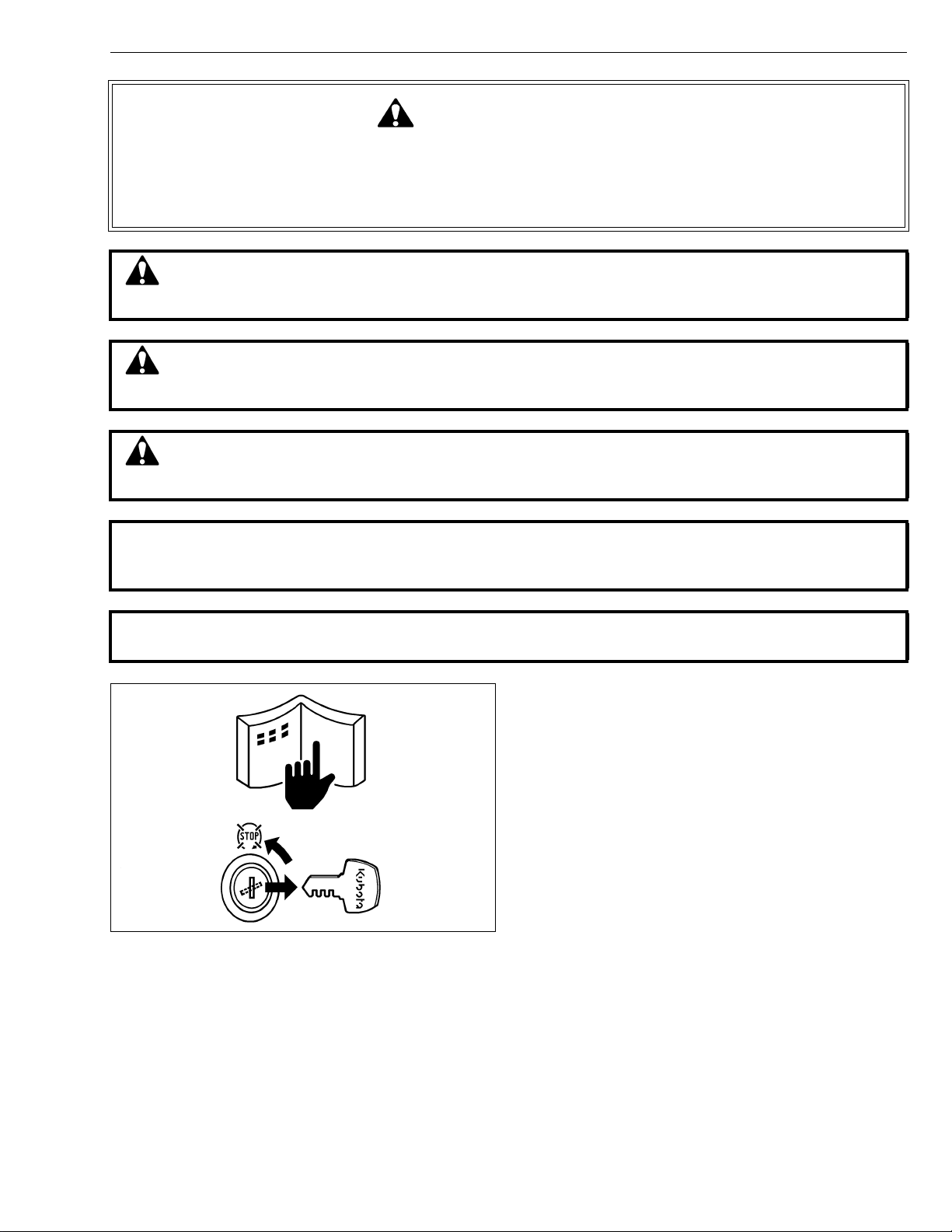
This symbol, the industry’s “Safety Alert Symbol”, is used throughout this manual and on labels on
the machine itself to warn of the possibility of personal injury. Read these instructions carefully.
It is essential that you read the instructions and safety regulations before you attempt to repair or use
this unit.
DANGER : Indicates an imminently hazardous situation which, if not avoided, will result in
death or serious injury.
WARNING : Indicates a potentially hazardous situation which, if not avoided, could result in
death or serious injury.
CAUTION : Indicates a potentially hazardous situation which, if not avoided, may result in
minor or moderate injury.
■ IMPORTANT : Indicates that equipment or property damage could result if instructions are not
followed.
■ NOTE : Gives helpful information.
BEFORE SERVICING AND REPAIRING
• Read all instructions and safety instructions in this
manual and on your machine safety decals.
• Clean the work area and machine.
• Park the machine on a firm and level ground, and set
the parking brake.
• Lower the implement to the ground.
• Stop the engine, and remove the key.
• Disconnect the battery negative cable.
• Hang a “DO NOT OPERATE” tag in operator station.
1
Page 4

ZD21N-EC, ZD21-EC, ZD28-EC, WSM
KiSC issued 09, 2006 A
SAFETY INSTRUCTIONS
SAFETY STARTING
• Do not start the engine by shorting across starter
terminals or bypassing the safety start switch.
• Do not alter or remove any part of machine safety
system.
• Before starting the engine, make sure that all shift
levers are in neutral positions or in disengaged
positions.
• Never start the engine while standing on ground.
Start the engine only from operator’s seat.
SAFETY WORKING
• Do not work on the machine while under the influence
of alcohol, medication , or other substances or while
fatigued.
• Wear close fitting clothing and safety equipment
appropriate to the job.
• Use tools appr opriate to the work. Mak eshift tools,
parts, and procedures are not recommended.
• When servicing is performed together by two or more
persons, take care to perform all work safely.
• Do not work under the machine that is supported
solely by a jack. Always support the machine by
safety stands.
• Do not touch the rotating or hot parts while the engine
is running.
• Never remove the radiator cap while the engine is
running, or immediately after stopping. Otherwise,
hot water will spout out fr om radiator. Only remove
radiator cap when cool enough to touch with bare
hands. Slowly loosen the cap to first stop to relieve
pressure before removing completely.
• Escaping fluid (fuel or hydraulic oil) un der pressure
can penetrate the skin causing serious injury. Relieve
pressure before disconnecting hydraulic or fuel lines.
Tighten all connections before applying pressure.
AVOID FIRES
• Fuel is extremely flammable and explosive under
certain condition s. Do not smoke or allow flames o r
sparks in your working area.
• To avoid sparks from an accidental short circuit,
always disconnect the battery negative cable first and
connect it last.
• Battery gas can explode. Keep sparks and open
flame away from the top of b attery, especially when
charging the battery.
• Mark sure that no fuel has been spilled on the engine.
2
Page 5
ZD21N-EC, ZD21-EC, ZD28-EC, WSM
KiSC issued 09, 2006 A
SAFETY INSTRUCTIONS
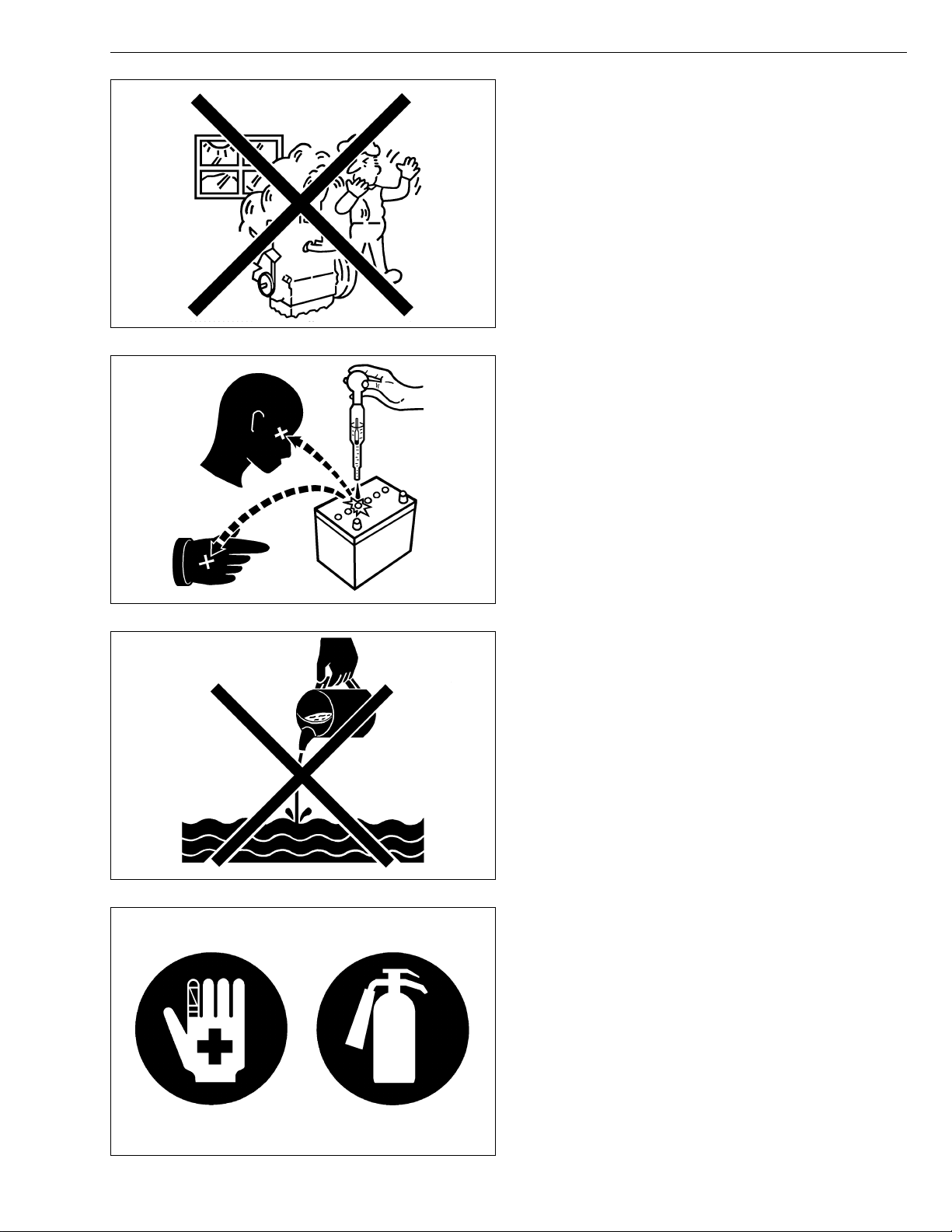
VENTILATE WORK AREA
• If the engine must be running to do some work, make
sure the area is well ventilated. Never run the engine
in a closed area. The exhaust gas contains
poisonous carbon monoxide.
PREVENT ACID BURNS
• Sulfuric acid in battery electr olyte is po isonous. It is
strong enough to burn skin, clothing and cause
blindness if splashed into eyes. Keep electrolyte
away from eyes, hands and clothing. If you spill
electrolyte on yourself, flush with water, and get
medical attention immediately.
DISPOSE OF FLUIDS PROPERLY
• Do not pour fluids into the ground, down a drain, or
into a stream, pond, or lake. Observe relevant
environmental prot ectio n regulati ons whe n disp osing
of oil, fuel, coolant, electrolyte and other harmful
waste.
PREPARE FOR EMERGENCIES
• Keep a first aid kit and fire extingui sher handy at all
times.
• Keep emergency numbers for doctors, ambulance
service, hospital and fire department near your
telephone.
3
Page 6
ZD21N-EC, ZD21-EC, ZD28-EC, WSM
KiSC issued 09, 2006 A
SAFETY INSTRUCTIONS
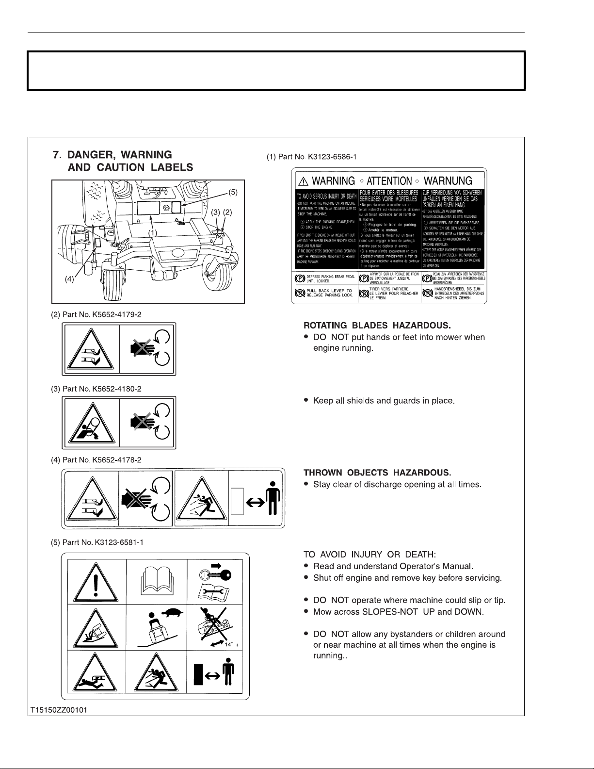
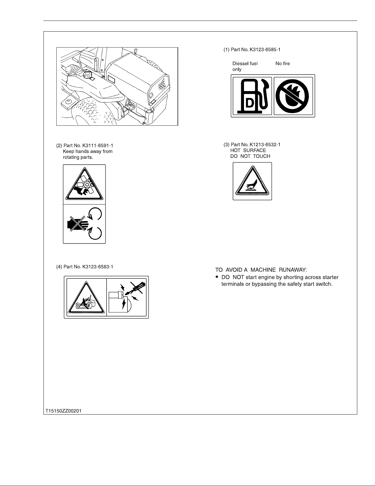
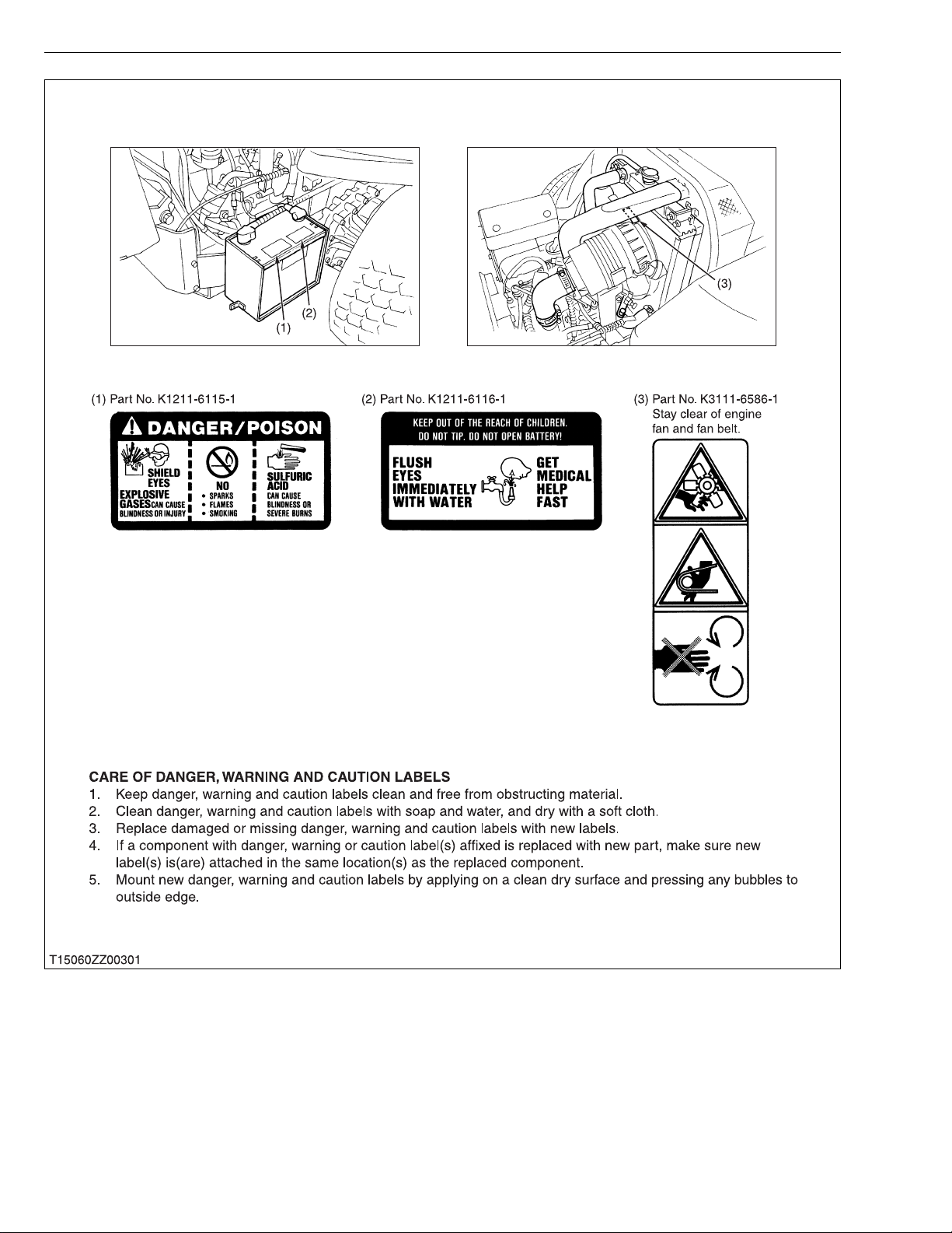
SAFETY DECALS
· The following safety decals are installed on the machine.
If a decal becomes dama ged , il legib le or is no t o n t he ma chin e, repla ce i t. Th e de cal p art nu mb er is list ed
in the parts list.
4
Page 7
ZD21N-EC, ZD21-EC, ZD28-EC, WSM
KiSC issued 09, 2006 A
SAFETY INSTRUCTIONS
5
Page 8
ZD21N-EC, ZD21-EC, ZD28-EC, WSM
KiSC issued 09, 2006 A
SAFETY INSTRUCTIONS
6
Page 9
ZD21N-EC, ZD21-EC, ZD28-EC, WSM
KiSC issued 09, 2006 A
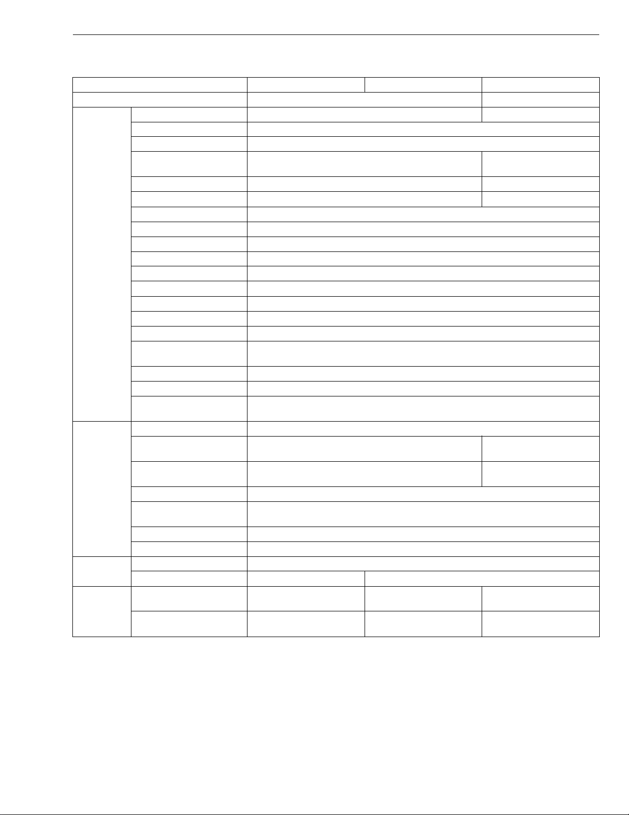
SPECIFICATIONS
Model ZD21N-EC ZD21-EC ZD28-EC
Maximum gross power (SAE) 15.7 kW (21 HP)*
Model D782-E-XFM5 D1105-E2-ZD
Type Indirect injection, vertical, water cooled, 4-cycle diesel engine
Number of cylinders 3
Bore and stroke 67.0 × 73.6 mm (2.64 × 2.90 in.) 78.0 × 78.4 mm
Total displacement 778 cm
Rated revolution 3200 rpm 3000 rpm
Combustion chamber Spherical type (E-TVCS)
Fuel injection pump Bosch MD type mini pump
Governor Centrifugal ball mechanical governor
Engine
Injection nozzle Bosch throttle type
Injection timing 0.33 to 0.37 rad (19° to 21°) before T.D.C.
Injection order 1-2-3
Injection pressure 13.73 MPa (140 kgf/cm
Lubricating system Forced Iubrication by gear pump
Cooling system Pressurized radiator, forced circulation with water pump
Lubricating oil
Starting system Electric starter (12 V, 1.1 kW)
Battery 51 R (12 V, 450 CCA)
Fuel
Fuel tank 30 L (5.8 U.S.gals., 4.8 lmp.gals.)
Engine crankcase 3.5 L (3.7 U.S.qts., 3.1 Imp.qts.)
Engine coolant
Capacities
Recovery tank 0.25 L (0.26 U.S.qts., 0.22 Imp.qts.)
Transmission (Including
HST and cylinder)
Rear axle gear case 1.8 L (1.9 U.S.qts., 1.6 Imp.qts.)*2 each
Mower gear case oil 0.40 L (0.42 U.S.qts., 0.35 Imp.qts.)
Tires
Travelling
speeds
Front 15 × 6.0-6 (4PR) Rib
Rear 23 × 10.5-12 (4PR) Turf 24 × 12.0-12 (4PR) Turf
Forward
Reverse
NOTE: *1 Manufacturer’s estimate
2
Oil amount when the oil level is at the upper level.
*
3
At 3200 engine rpm
*
4
At 3000 engine rpm
*
API Service classification CC or CD, Below 0 °C (32 °F) : SAE 10W or 10W-30, 0 to 25 °C
(32 °F to 77 ° F) : SAE 20 or 10W-30, Above 25 °C (77 °F) : SAE 30 or 10W-30
[No. 1-D diesel fuel, if temperature is below – 10 °C (14 °F)]
2.6 L (2.7 U.S.qts., 2.3 Imp.qts.)
0 to 14.5 km/h
(0 to 9.0 mph)*
0 to 8.0 km/h
(0 to 5.0 mph)*
3
(47.5 cu.in.) 1123 cm3 (68.5 cu.in.)
No. 2-D Diesel fuel (ASTM D975)
4.0 L (4.2 U.S.qts., 3.5 Imp.qts.)*
3
3
1
0 to 15.0 km/h
(0 to 9.3 mph)*
0 to 8.3 km/h
(0 to 5.2 mph)*
2
, 1990 psi)
3
3
SPECIFICATIONS
20.9 kW (28 HP)*
(3.07 × 309 in.)
3.4 L
(3.6 U.S.qts., 3.0 Imp.qts.)
3.8 L
(4.0 U.S.qts., 3.3 Imp.qts.)
2
0 to 15.0 km/h
(0 to 9.3 mph)*
0 to 8.3 km/h
(0 to 5.2 mph)*
1
4
4
W1028929
7
Page 10
ZD21N-EC, ZD21-EC, ZD28-EC, WSM
KiSC issued 09, 2006 A
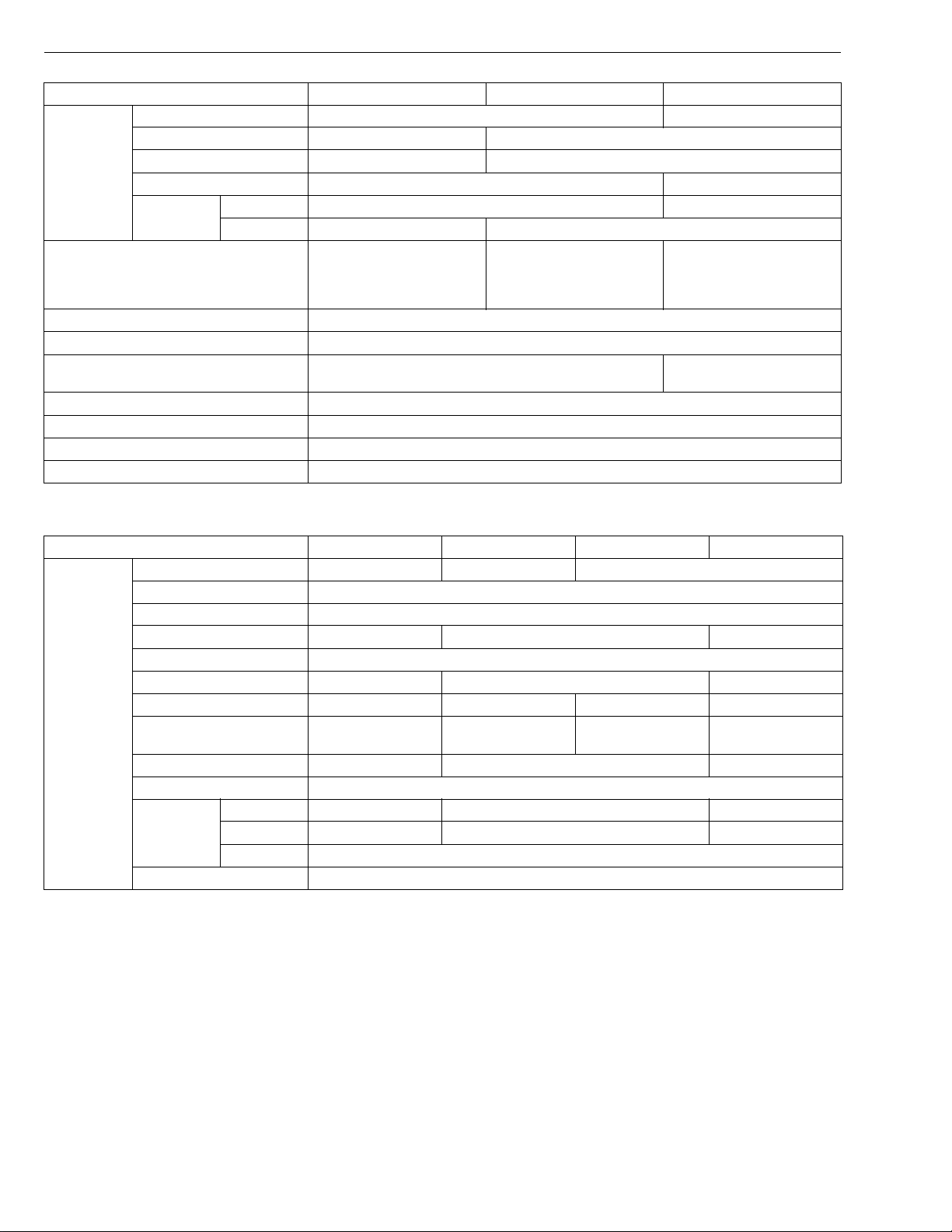
Model ZD21N-EC ZD21-EC ZD28-EC
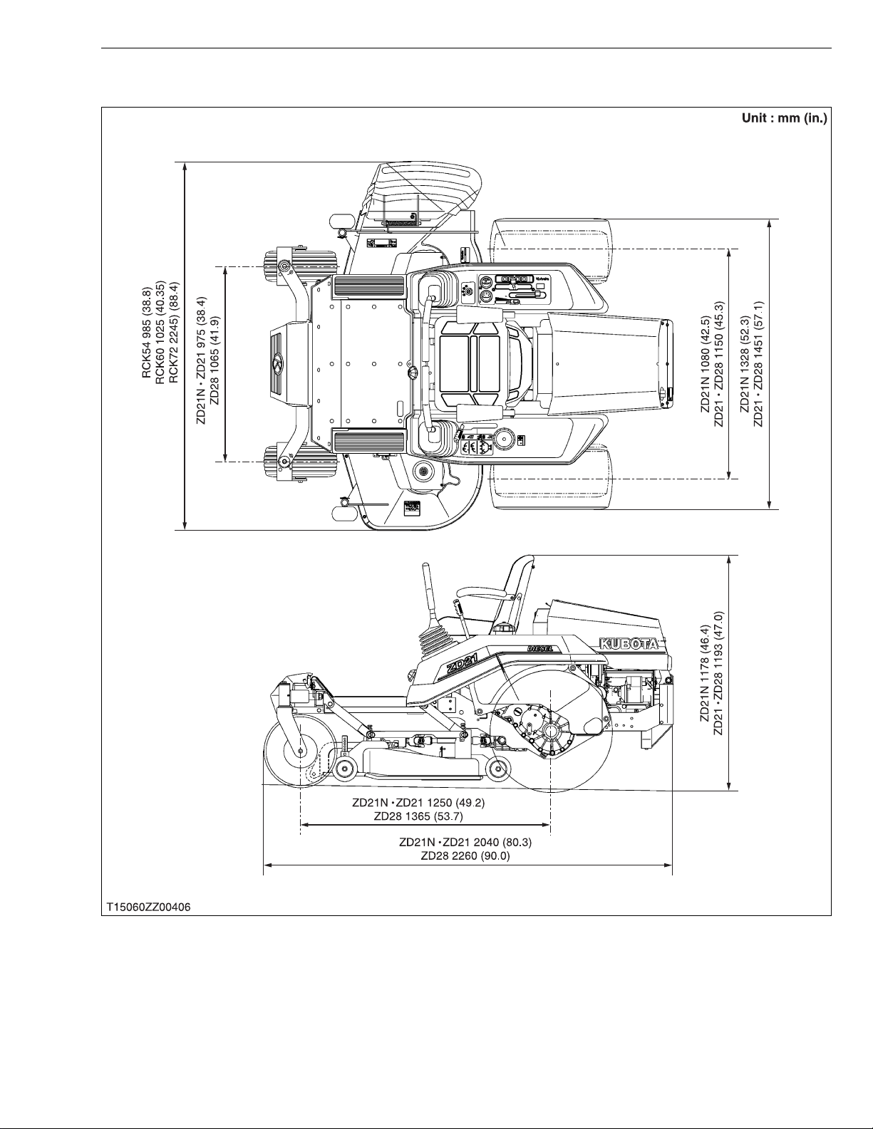
Overall length 2040 mm (80.3 in.) 2260 mm (90.0 in.)
Overall width (Without mower)
Dimensions
Weight (With mower deck)
PTO Shaft drive KUBOTA 10 tooth in spline
PTO clutch Wet multi discs
Revolution (PTO speed)
PTO brake Wet single disc
Steering 2-Hand levers
Transmission 2-Hydrostatic transmission with gear
Brake Internal expanding shoe / Hand
The company reserves the right to change the specifications without notice.
Overall height
Wheel base 1250 mm (49.2 in.) 1365 mm (53.7 in.)
Treads
Front 975 mm (38.4 in.) 1065 mm (41.9 in.)
Rear 1080 mm (42.5 in.) 1150 mm (45.3 in.)
1328 mm (52.3 in.) 1451 mm (57.1 in.)
1178 mm (46.4 in.) 1193 mm (47.0 in.)
570 kg (1256.6 lbs) / With
560 kg (1234.8 lbs) / With
54" mower deck
1 speed (2530 rpm at 3200 engine rpm)
60" mower deck
SPECIFICATIONS
652 kg (1437.7 lbs) / With
60" mower deck
676 kg (1490.6 lbs) / With
72” mower deck
1 speed (2540 rpm at 3000
engine rpm)
W1031261
Model RCK54-21NZ-EC RCK54-21NZ-EC RCK60-28Z-EC RCK72-28Z-EC
Suitable machine ZD21N-EC ZD21N-EC ZD28-EC
Mounting method Quick joint, parallel linkage
Adjustment of cutting height Dial gauge
Cutting width 1372 mm (54.0 in.) 1524 mm (60.0 in.) 1829 mm (72.0 in.)
Cutting height 25 to 127 mm (1.0 to 5.0 in.)
Weight (Approx.) 103 kg (227 lbs) 120 kg (265 lbs) 150 kg (331 lbs)
Blade spindle speed 50.1 r/s (3006 rpm) 44.6 r/s (2676 rpm) 44.8 r/s (2688 rpm) 40.0 r/s (2400 rpm)
Mower
The company reserves the right to change the specifications without notice.
Blade tip velocity 74.7 m/s
(14701 fpm)
Blade length 475 mm (18.7 in.) 523 mm (20.6 in.) 625 mm (24.6 in.)
Number of blades 3
Total length 985 mm (38.8 in.) 1025 mm (40.4 in.) 1095 mm (43.1 in.)
Dimensions
Discharge Right side
Total width 1690 mm (60.5 in.) 1845 mm (72.6 in.) 2245 mm (88.4 in.)
Total height 300 mm (11.8 in.)
73.4 m/s
(14445 fpm)
73.6 m/s
(14484 fpm)
78.5 m/s
(15449 fpm)
W1029898
8
Page 11
ZD21N-EC, ZD21-EC, ZD28-EC, WSM
KiSC issued 09, 2006 A
DIMENSIONS
DIMENSIONS
9
Page 12

G GENERAL
KiSC issued 09, 2006 A
Page 13

GENERAL
KiSC issued 09, 2006 A
CONTENTS
1. IDENTIFICATION............................................................................................. G-1
2. GENERAL PRECAUTIONS ............................................................................ G-2
3. HANDLING PRECAUTIONS FOR ELECTRICAL PARTS AND WIRING..G-3
[1] WIRING...................................................................................................... G-3
[2] BATTERY................................................................................................... G-5
[3] FUSE.......................................................................................................... G-5
[4] CONNECTOR............................................................................................ G-5
[5] HANDLING OF CIRCUIT TESTER......................................................... G-6
4. LUBRICANTS, FUEL AND COOLANT ......................................................... G-7
5. TIGHTENING TORQUES ............................. ....... ...... ....... ...... ....... ...... ....... .... G- 9
[1] GENERAL USE SCREWS, BOLTS AND NUTS................................... G-9
[2] STUD BOLTS............................................................................................ G-9
[3] METRIC SCREWS, BOLTS AND NUTS ............................................. G-10
[4] AMERICAN STANDARD SCREWS, BOLTS AND NUTS WITH UNC
OR UNF THREADS ............................................................................... G-10
[5] PLUGS..................................................................................................... G-10
6. MAINTENANCE CHECK LIST..................................................................... G-11
7. CHECK AND MAINTENANCE......... ...... ...... ....................................... ....... .. G-13
[1] DAILY CHECK........................................................................................ G-13
[2] CHECK POINTS OF INITIAL 50 HOURS........................................... G-17
[3] CHECK POINT OF INITIAL 100 HOURS ........................................... G-19
[4] CHECKING POINTS OF INITIAL 200 HOURS................................... G-20
[5] CHECK POINTS OF EVERY 50 HOURS........................................... G-22
[6] CHECK POINTS OF EVERY 100 HOURS......................................... G-26
[7] CHECK POINTS OF EVERY 150 HOURS......................................... G-31
[8] CHECK POINTS OF EVERY 200 HOURS......................................... G-31
[9] CHECK POINTS OF EVERY 400 HOURS......................................... G-33
[10]CHECK POINTS OF EVERY 1 YEAR................................................ G-33
[11]CHECK POINT OF EVERY 2 YEARS ................................................ G-36
[12]OTHERS .................................................................................................. G-37
8. SPECIAL TOOLS.......................................................................................... G-39
[1] SPECIAL TOOLS FOR ENGINE .......................................................... G-39
[2] SPECIAL TOOLS FOR MACHINE........................................................ G-45
Page 14
ZD21N-EC, ZD21-EC, ZD28-EC, WSM
KiSC issued 09, 2006 A
1. IDENTIFICATION
G GENERAL
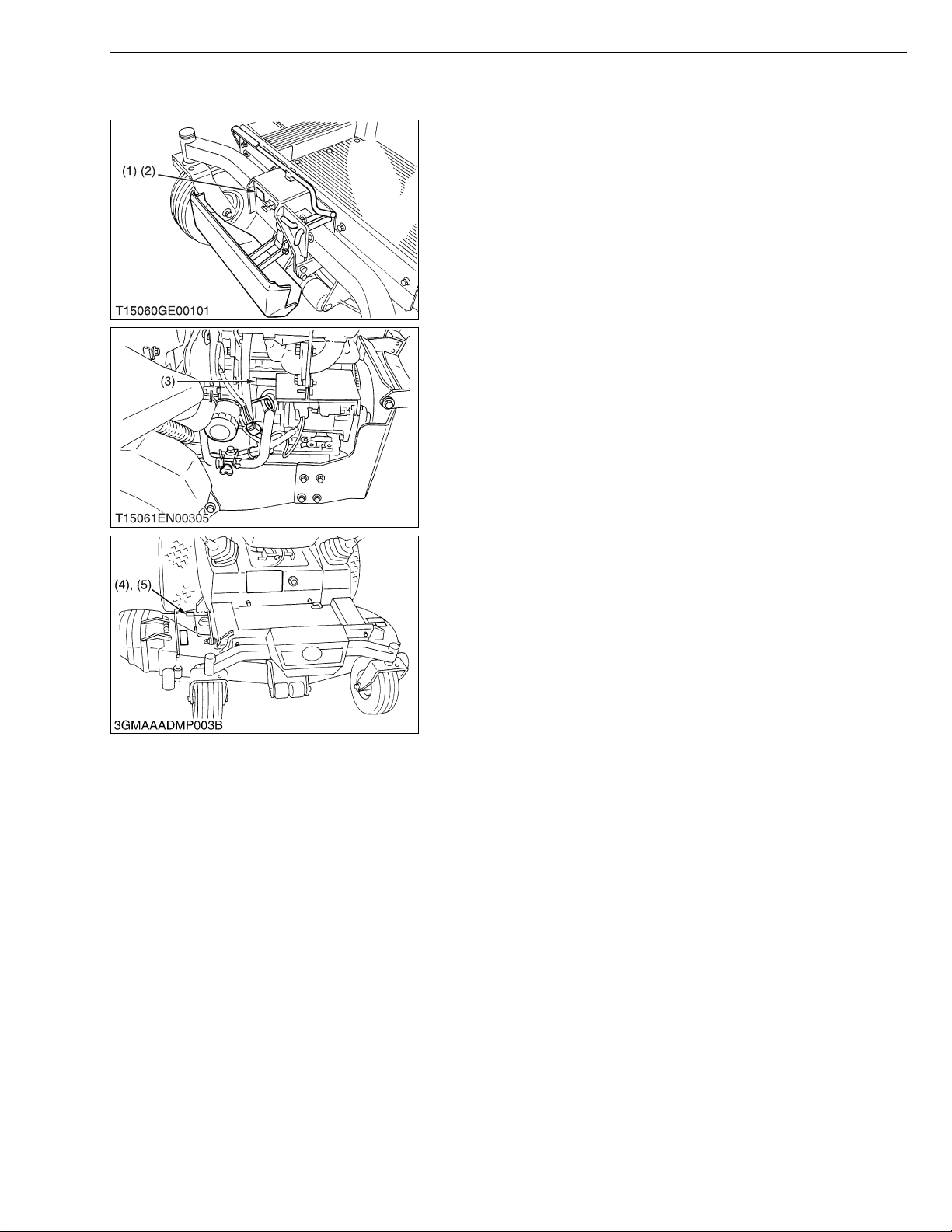
When contacting your loca l KUBOTA distr ibutor, alway s specify
engine serial num ber (3), machine serial number (2 ), mower serial
number (4) and hour meter reading.
(1) Machine Identification Plate
(2) Machine Serial Number
(3) Engine Serial Number
(4) Mower Serial Number
(5) Mower Identification Plate
W1010714
G-1
Page 15
ZD21N-EC, ZD21-EC, ZD28-EC, WSM
KiSC issued 09, 2006 A
2. GENERAL PRECAUTIONS
• During disa ssembly, ca refully ar range removed parts in a cle an
area to prevent confusion later. Screws, bolts and nuts should be
installed in their original position to prevent reassembly errors.
• When special tools are requi red, use KUBOT A genuine speci al
tools. Special tools which are not frequently used should be
made according to the drawings provided.
• Before disassembling or servicing electrical wires, always
disconnect the ground cable from the battery first.
• Remove oil and dirt from parts before measuring.
• Use only KUBOTA genuine parts for parts replacement to
maintain machine performance and to assure safety.
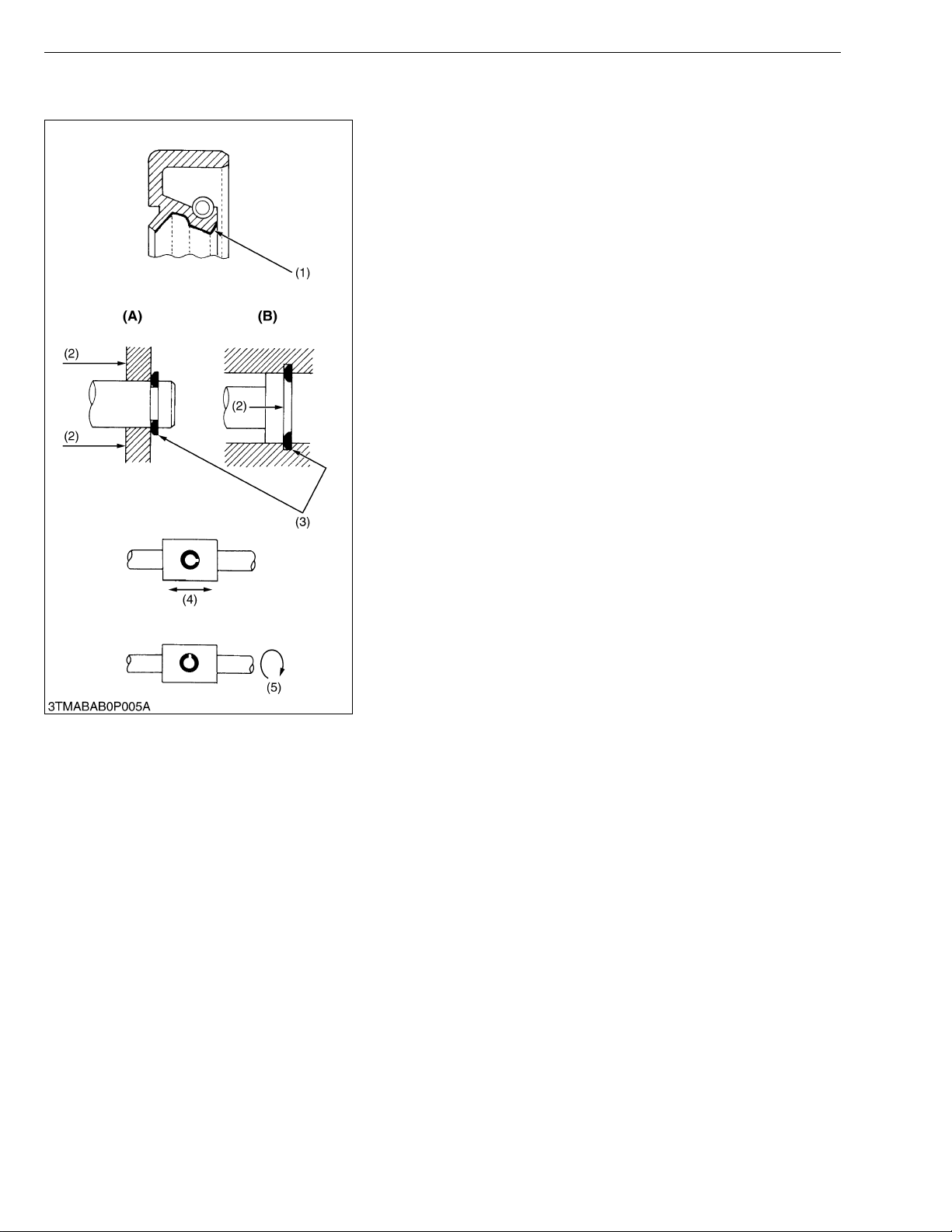
• Gaskets and O-rings must be replaced during reassembly.
Apply grease to new O-rings or oil seals before assembling.
See the figure left side.
• When reassem bling external snap rings or inte rnal snap rings,
they must be positioned so that sharp edge faces against the
direction from which a force is applied. See the figure left side.
• When insert ing spring pins, their splits must face the direction
from which a force is applied. See the figure left side.
• To prevent dam age to the hydraulic s ystem, use only sp ecified
fluid or equivalent.
(1) Grease
(2) Force
(3) Sharp Edge
(4) Axial Force
(5) Rotating Movement
G GENERAL
(A) External Snap Ring
(B) Internal Snap Ring
W1010904
G-2
Page 16
ZD21N-EC, ZD21-EC, ZD28-EC, WSM
IMPORTANT■
KiSC issued 09, 2006 A
G GENERAL
3. HANDLING PRECAUTIONS FOR ELECTRICAL PARTS
AND WIRING
To ensure safety and prevent damage to the machine and
surrounding equipm ent, heed the following pr ecautions in handling
electrical parts and wiring.
• Check electrical wiring for damage and loosened
connection every year. To this end, educate the customer to
do his or her own check and at the s ame time recommend
the dealer to perform periodic check for a fee.
• Do not attempt to modify or remodel any electrical parts and
wiring.
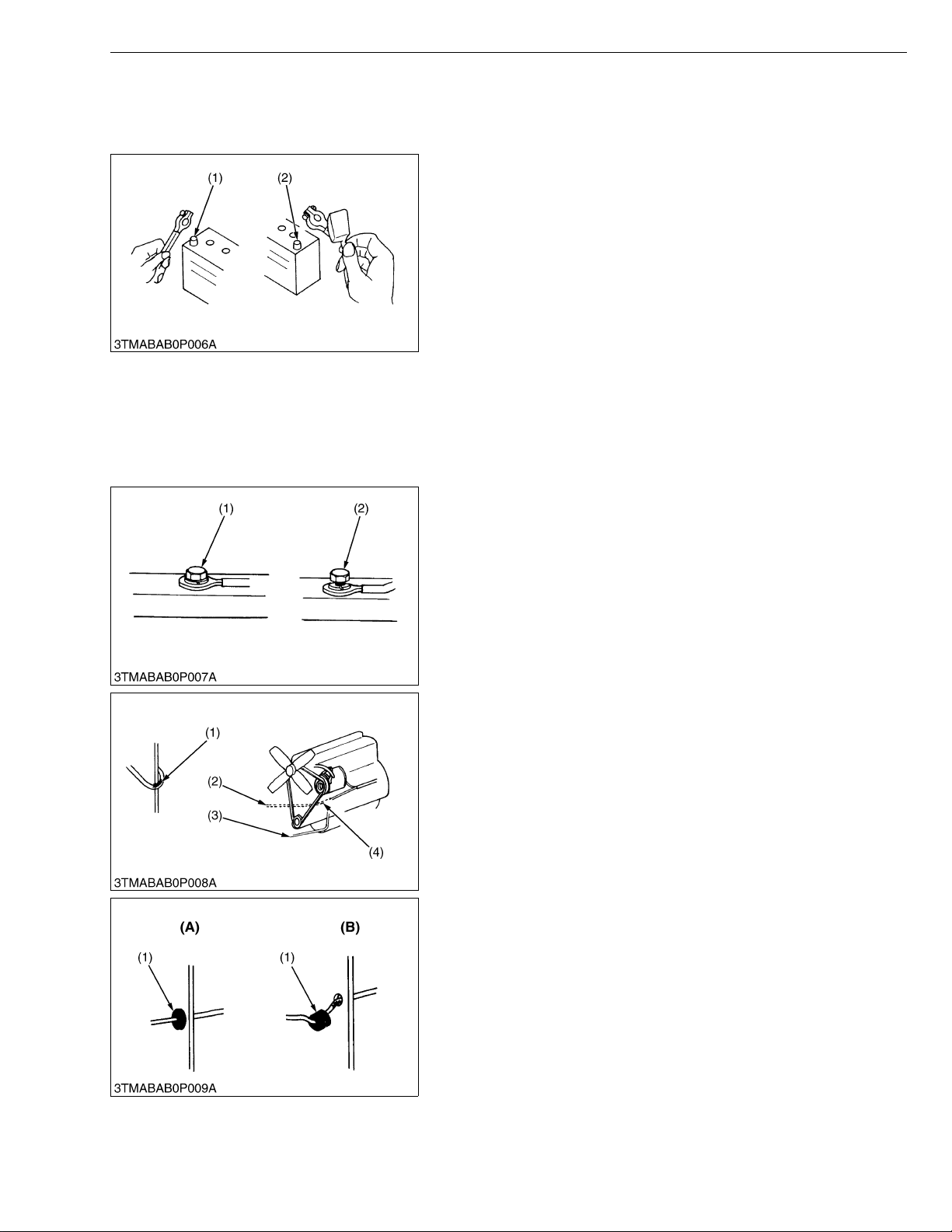
• When removing th e ba tter y cab le s, dis co nn ect t he n egat ive
cable first. When in stalling the b attery cables, c onnect the
positive cable first.
(1) Negative Terminal (2) Positive Terminal
W1011114
[1] WIRING
• Securely t ighten wiring terminals.
(1) Correct
(Securely tighten)
(2) Incorrect
(Loosening leads to faulty contact)
W1011216
• Do not let wiring contact dangerous part.
(1) Wiring (Correct)
(2) Wiring (Incorrect)
(3) Dangerous Part
(4) Dangerous Part
• Securely insert grommet.
(1) Grommet (A) Co rrect
(B) Incorrect
W1011313
W1011388
G-3
Page 17
ZD21N-EC, ZD21-EC, ZD28-EC, WSM
KiSC issued 09, 2006 A
G GENERAL
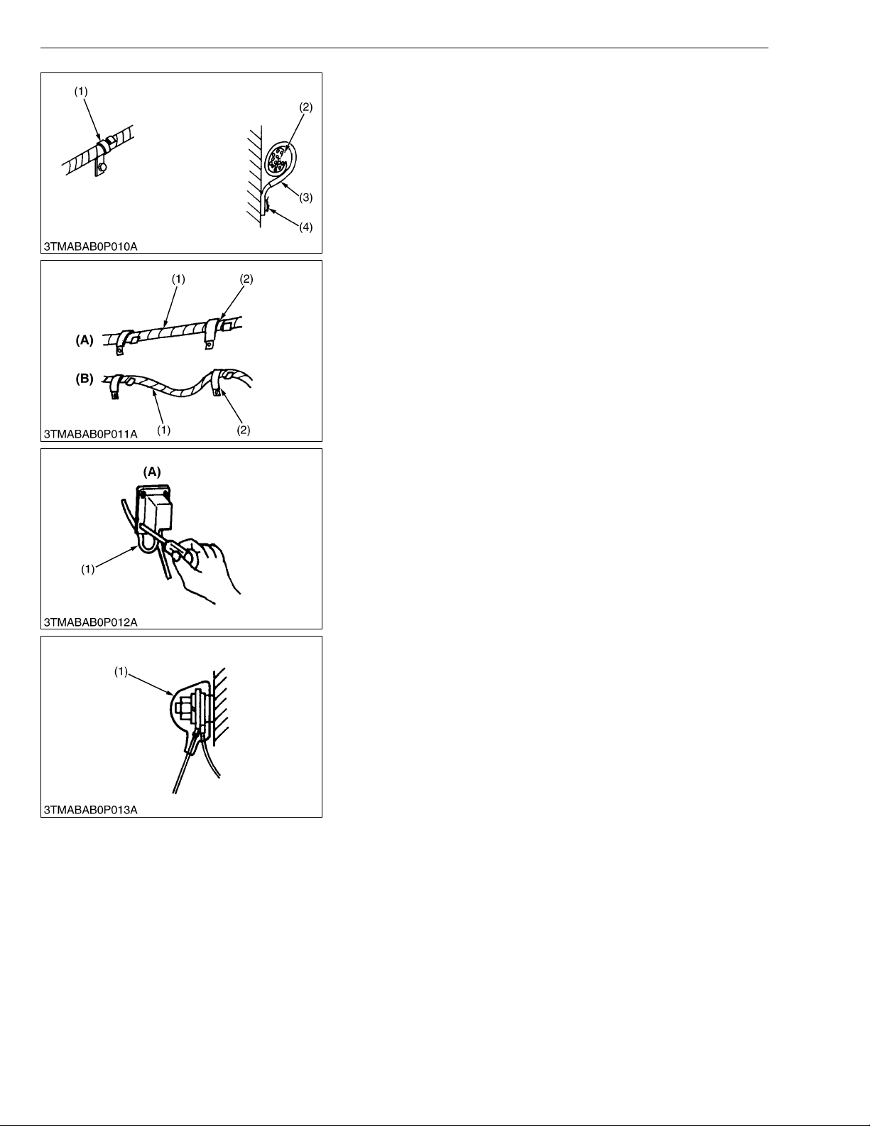
• Securely clamp, being careful not to damage wiring.
(1) Clamp
• Wind Clamp Spirally
(2) Wire Harness
(3) Clamp
(4) Welding Dent
W1011458
• Clamp wiring so that there is no twist, unnecessary sag, or
excessive tension, except for movable part, where sag be
required.
(1) Wiring
(2) Clamp
(A) Correct
(B) Incorrect
W1011587
• In installing a part, take care not to get wiring caught by it.
(1) Wiring (A) Incorrect
W1011670
• After installing wiring, check protection of terminals and clamped
condition of wiring, only connect battery.
(1) Cover
• Securely Install Cover
W1011735
G-4
Page 18
ZD21N-EC, ZD21-EC, ZD28-EC, WSM
KiSC issued 09, 2006 A
[2] BATTERY
[3] FUSE
G GENERAL
• Take care not to confuse positive and negative terminal posts.
• When removing b attery cables, disconnect negative cable first.
When installing battery cables, check for polarity and connect
positive cable first.
• Do not install a ny battery with capacity other than is specified
(Ah).
• After connecting cables to battery terminal posts, apply high
temperature grease to them a nd sec urely in stall t erminal covers
on them.
• Do not allow dirt and dust to collect on battery.
CAUTION
• Take care not to let battery liquid spill on your skin and
clothes. If contaminated, wash it off with water immediately.
• Before recharging the battery, remove it from the machine.
• Before recharging, remove cell caps.
• Do recharging in a well- ventilated place where there is no
open flame nearby, as hydrogen gas and oxygen are formed.
W1011816
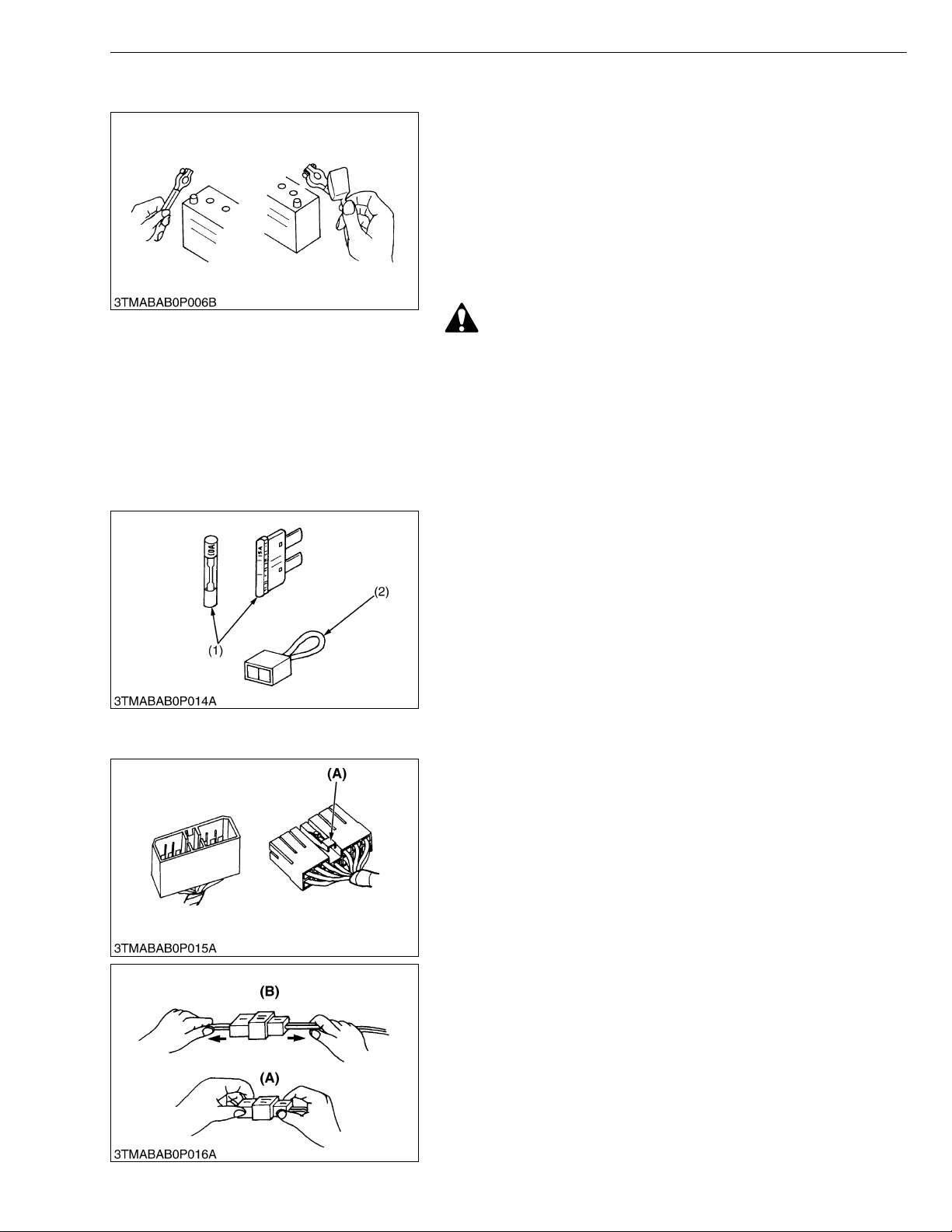
[4] CONNECTOR
• Use fuses with specified capacity.
Neither too large or small capacity fuse is acceptable.
• Never use steel or copper wire in place of fuse.
• Do not install working light, radio set, etc. on machine which is not
provided with reserve power supply.
• Do not install accessories if fuse capacity of reserve power
supply is exceeded.
(1) Fuse (2) Slow Blow Fuse
W1012092
• For connector with lock, push lock to separate.
(A) Push
W1012211
• In separating connectors, do not pull wire harnesses.
• Hold connector bodies to separate.
(A) Correct (B) Incorrect
W1012272
G-5
Page 19

ZD21N-EC, ZD21-EC, ZD28-EC, WSM
KiSC issued 09, 2006 A
G GENERAL
• Use sandpaper to remove rust from terminals.
• Repair deformed terminal. Make certain there is no terminal
being exposed or displaced.
(1) Exposed Terminal
(2) Bend Terminal
(3) Sandpaper
(4) Rust
W1012346
• Make certain that there is no female connector being too open.
(A) Correct (B) Incorrect
W1012430
[5] HANDLING OF CIRCUIT TESTER
• Use tester correctly following manual provided with tester.
• Check for polarity and range .
W1012684
G-6
Page 20
ZD21N-EC, ZD21-EC, ZD28-EC, WSM
KiSC issued 09, 2006 A
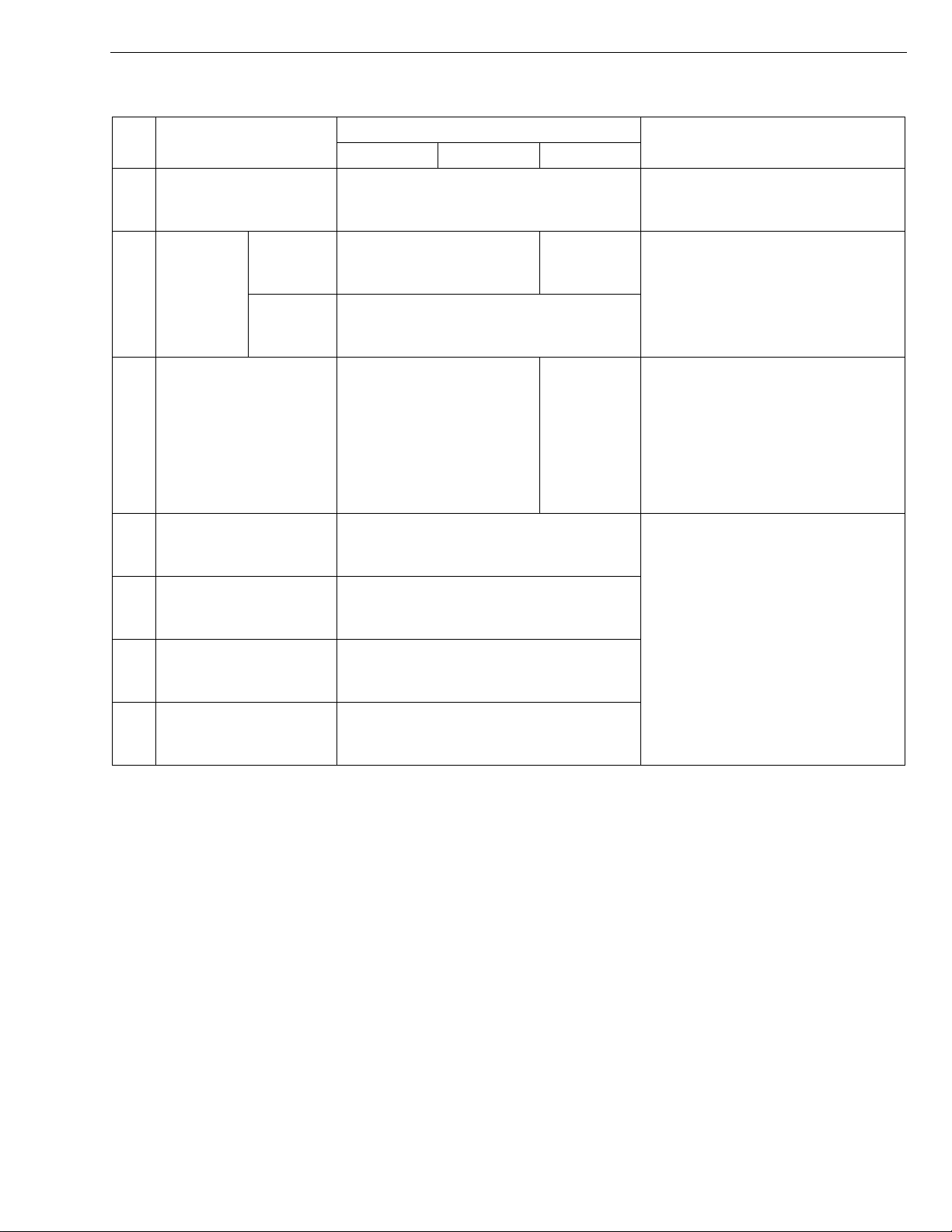
4. LUBRICANTS, FUEL AND COOLANT
G GENERAL
No. Place
1Fuel
Cooling
system
2Coolant
Recovery
tank
3 Engine crankcase
4 T ransmission case
Transmission case with
5
filter & hose
6 Rear axle case
7 Mower gear case
* Oil amount when the oil level is the upper of the oil level gauge.
** KUBOTA original transmission hydraulic fluid
ZD21N-EC ZD21-EC ZD28-EC
2.7 U.S.qts.
2.3 Imp.qts.
3.7 U.S.qts.
3.1 Imp.qts.
Capacity
30 L
7.9 U.S.gals.
6.6 Imp.gals.
2.6 L
4.0 U.S.qts.
3.3 Imp.qts.
0.25 L
0.26 U.S.qts.
0.22 Imp.qts.
3.5 L*
3.6 U.S.qts.
3.0 Imp.qts.
3.2 L
3.4 U.S.qts.
2.8 Imp.qts.
4.0 L
4.2 U.S.qts.
3.5 Imp.qts.
1.8 L each
1.9 U.S.qts. each
1.6 Imp.qts. each
0.40 L
0.42 U.S.qts.
0.35 Imp.qts.
3.8 L
3.4 L*
Lubricants, fuel and coolant
No. 2-D diesel fuel
No. 1-D diesel fuel if temperature is
below – 10 °C (14 °F)
Fresh clean water (soft water) with
anti-freeze
Engine oil : API Service
Classification CC or CD
Below 0 °C (32 °F) : SAE10W,
10W-30 or 10W-40
0 to 25 °C (32 to 77 °F): SAE20,
10W-30 or 10W-40
Above 25 °C (77 °F): SAE30, 10W30 or 10W-40
KUBOTA UDT or SUPER UDT
fluid**
G-7
Page 21
ZD21N-EC, ZD21-EC, ZD28-EC, WSM
KiSC issued 09, 2006 A
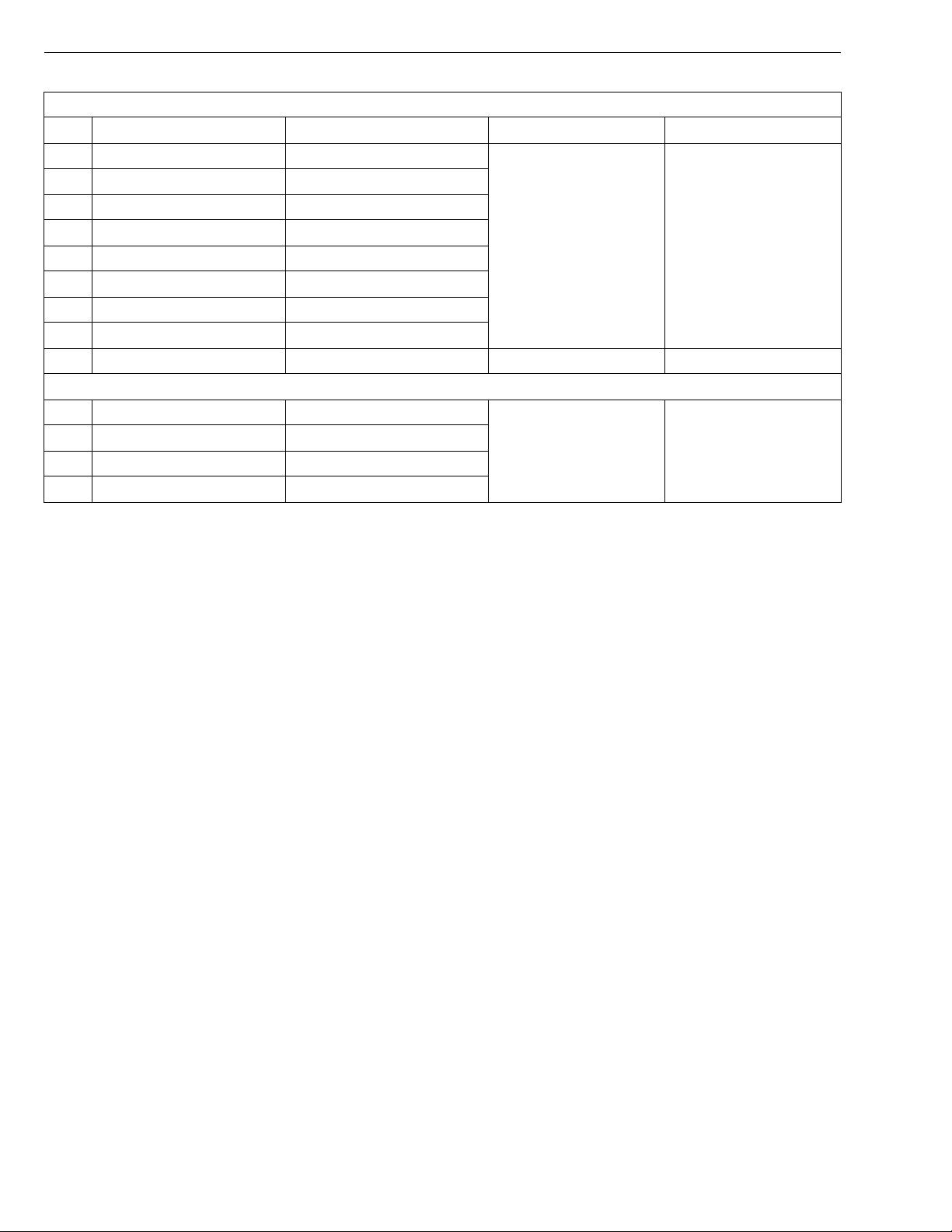
G GENERAL
Greasing, oiling (Machine)
No. Place No. of greasing point Capacity Type of grease
7 Speed control lever boss 2
8 Speed control lever 2
9 Center pin 1
10 King pin 2
Until grease overflows
11 Front wheel 2
SAE multi-purpose
type grease
12 Front lift arm 2
13 Universal joint 3
14 Seat adjuster 2
15 Throttle cable 2 Moderate amount Engine oil
Greasing (Mower)
16 Universal joint 3
17 Three spindle shafts 3
Until grease overflows
18 Belt tension pulley 1
SAE multi-purpose
type grease
19 Belt tension pivot 1
G-8
Page 22
ZD21N-EC, ZD21-EC, ZD28-EC, WSM
KiSC issued 09, 2006 A
G GENERAL
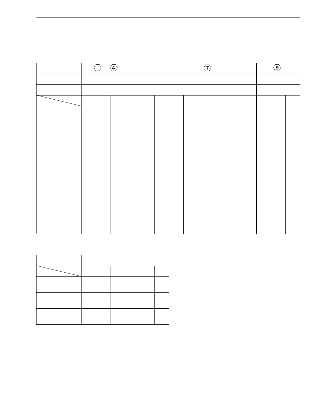
5. TIGHTENING TORQUES
[1] GENERAL USE SCREWS, BOLTS AND NUTS
Screws, bolts and nu ts whose tightening torques are not speci fied in t his Worksh op Manual should b e tightened
according to the table below.
Indication on top of
bolt
Material of bolt SS400, S20C S43C, S48C
Material of opponent
part
Unit
Diameter
M6
(6 mm, 0.24 in.)
M8
(8 mm, 0.31 in.)
M10
(10 mm, 0.39 in.)
M12
(12 mm, 0.47 in.)
M14
(14 mm, 0.55 in.)
M16
(16 mm, 0.63 in.)
M18
(18 mm, 0.71 in.)
M20
(20 mm, 0.79 in.)
No-grade or 4T 7T 9T
SCr435,
SCM435
Ordinariness Aluminum Ordinariness Aluminum Ordinariness
N·m kgf·m ft-lbs N·m kgf·m ft-lbs N·m kgf·m ft-lbs N·m kgf·m ft-lbs N·m kgf·m ft-lbs
7.85
0.80
5.79
7.85
0.80
5.79
9.81
1.00
7.24
7.85
0.80
5.79
12.3
to
9.31
17.7
to
20.5
39.3
to
45.1
62.8
to
72.5
108
to
125
167
to
191
246
to
284
334
to
392
to
0.95
1.8
to
2.1
4.0
to
4.6
6.4
to
7.4
11.0
to
12.8
17.0
to
19.5
25.0
to
29.0
34.0
to
40.0
to
6.87
13.1
to
15.1
29.0
to
33.2
46.3
to
53.5
79.6
to
92.5
123
to
141
181
to
209
246
to
289
to
to
to
8.82
0.90
6.50
16.7
19.6
31.4
34.3
1.7
12.3
to
to
2.0
3.2
to
3.5
–––
–––
–––
–––
–––
to
14.4
23.2
to
to
25.3
to
11.2
23.6
to
27.4
48.1
to
55.8
77.5
to
90.2
124
to
147
197
to
225
275
to
318
368
to
431
to
1.15
2.4
to
2.8
4.9
to
5.7
7.9
to
9.2
12.6
to
15.0
20.0
to
23.0
28.0
to
32.5
37.5
to
44.0
to
8.31
17.4
to
20.2
35.5
to
41.2
57.2
to
66.5
91.2
to
108
145
to
166
203
to
235
272
to
318
to
to
to
8.82
0.90
6.50
17.7
20.5
39.3
44.1
62.8
72.5
1.8
13.1
to
to
2.1
4.0
to
4.5
6.4
to
7.4
–––
–––
–––
–––
to
15.1
29.0
to
to
32.5
46.3
to
to
53.5
to
14.2
29.5
to
34.3
60.9
to
70.6
103
to
117
167
to
196
260
to
304
344
to
402
491
to
568
1.25
to
1.45
3.0
to
3.5
6.2
to
7.2
10.5
to
12.0
17.0
to
20.0
26.5
to
31.0
35.0
to
41.0
50.0
to
58.0
W1034542
9.05
to
10.4
21.7
to
25.3
44.9
to
52.0
76.0
to
86.7
123
to
144
192
to
224
254
to
296
362
to
419
[2] STUD BOLTS
Material of opponent
part
Unit
Diameter
M8
(8 mm, 0.31 in.)
M10
(10 mm, 0.39 in.)
M12
(12 mm, 0.47 in.)
Ordinariness Aluminum
N·m kgf·m ft-lbs N·m kgf·m ft-lbs
11.8
to
15.6
24.6
to
31.3
29.5
to
49.0
1.2
to
1.6
2.5
to
3.2
3.0
to
5.0
8.68
8.82
to
11.5
18.1
23.1
21.7
36.1
to
11.8
19.7
to
to
25.4
to
31.4 3.2 23.1
0.90
to
1.2
2.0
to
2.6
6.51
to
8.67
14.5
to
18.8
W10481390
G-9
Page 23
ZD21N-EC, ZD21-EC, ZD28-EC, WSM
KiSC issued 09, 2006 A
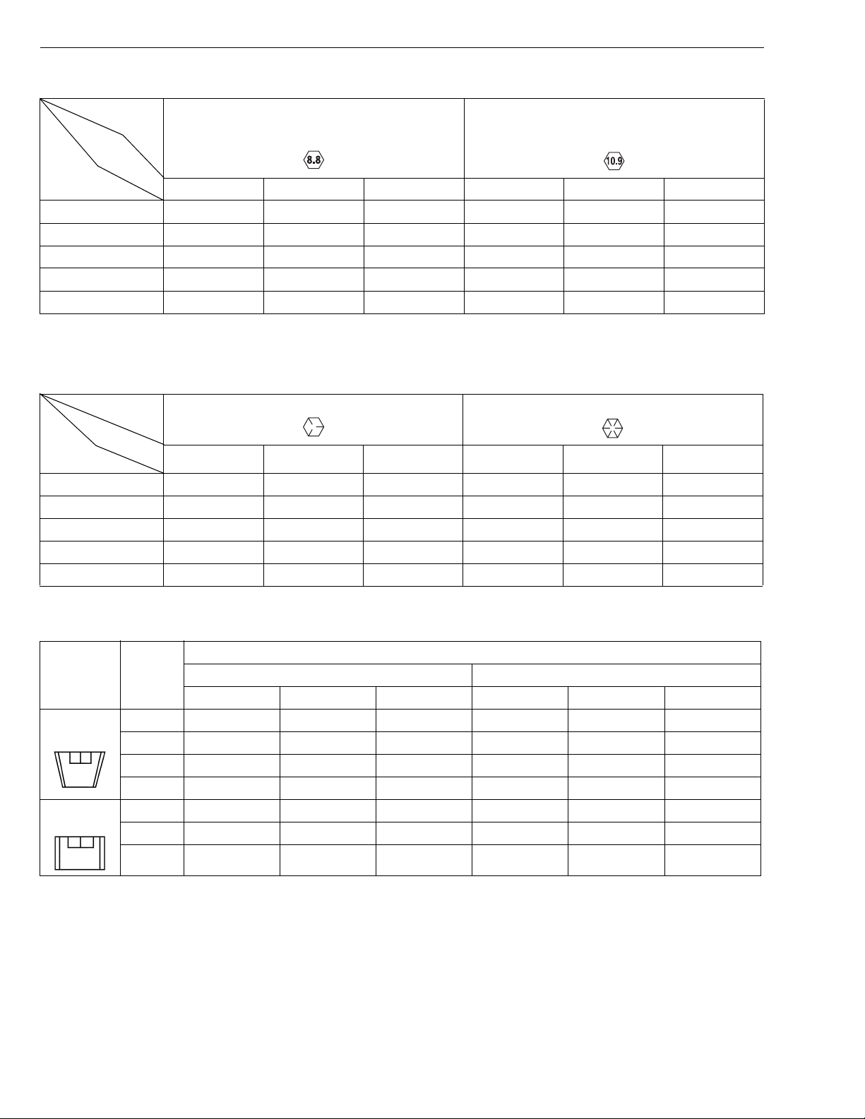
[3] METRIC SCREWS, BOLTS AND NUTS
G GENERAL
Grade
Unit
Nominal
Diameter
M8 23.6 to 27.4 2.4 to 2.8 17.4 to 20.2 29.4 to 34.3 3.0 to 3.5 21.7 to 25.3
M10 48.1 to 55.8 4.9 to 5.7 35.5 to 41.2 60.8 to 70.5 6.2 to 7.2 44.9 to 52.1
M12 77.5 to 90.1 7.9 to 9.2 57.2 to 66.5 103.0 to 117.0 10.5 to 12.0 76.0 to 86.8
M14 124.0 to 147.0 12.6 to 15.0 91.2 to 108.0 167.0 to 196.0 17.0 to 20.0 123.0 to 144.0
M16 196.0 to 225.0 20.0 to 23.0 145.0 to 166.0 260.0 to 303.0 26.5 to 31.0 192.0 to 224.0
N·m kgf·m ft-lbs N·m kgf·m ft-lbs
Property class 8.8 Property class 10.9
0000001413E
[4] AMERICAN STANDARD SCREWS, BOLTS AND NUTS WITH UNC OR
UNF THREADS
Grade
Unit
Nominal
Diameter
5/16 23.1 to 27.8 2.35 to 2.84 17.0 to 20.5 32.5 to 39.3 3.31 to 4.01 24.0 to 29.0
3/8 47.5 to 57.0 4.84 to 5.82 35.0 to 42.0 61.0 to 73.2 6.22 to 7.47 45.0 to 54.0
1/2 108.5 to 130.2 11.07 to 13.29 80 .0 to 96.0 149 .2 to 179.0 15.22 to 18.27 110.0 to 132.0
9/16 149.2 to 179.0 15 .22 to 18.27 110.0 to 132.0 217.0 to 260.4 22.14 to 26.57 160.0 to 192.0
5/8 203.4 to 244.1 20.75 to 24.91 150.0 to 180.0 298.3 to 358.0 30.44 to 36.53 220.0 to 264.0
N·m kgf·m ft-lbs N·m kgf·m ft-lbs
SAE GR.5 SAE GR.8
0000001414E
[5] PLUGS
Shape Size
Tapered
screw
Straight
screw
Material of opponent part
Ordinariness Aluminum
N·m kgf·m ft-lbs N·m kgf·m ft-lbs
R1/8 12.7 to 21.6 1.3 to 2.2 9.4 to 15.9 12.7 to 19.6 1.3 to 2.0 9.4 to 15.4
R1/4 24.5 to 44.1 2.5 to 4.5 18.1 to 32.5 24.5 to 34.3 2.5 to 3.5 18.1 to 25.4
R3/8 49.0 to 88.3 5.0 to 9.0 36.2 to 65.1 49.0 to 58.8 5.0 to 6.0 36.2 to 43.4
R1/2 58.8 to 107.9 6.0 to 11.0 43.4 to 79.6 58.8 to 78.5 6.0 to 8.0 43.4 to 57.4
G1/4 24.5 to 34.3 2.5 to 3.5 18.1 to 25.3 – – –
G3/8 61.8 to 82.4 6.3 to 8.4 45.6 to 60.8 – – –
G1/2 49.0 to 88.3 5.0 to 9.0 36.2 to 65.1 – – –
0000001666E
G-10
Page 24
ZD21N-EC, ZD21-EC, ZD28-EC, WSM
IMPORTANT■
KiSC issued 09, 2006 A
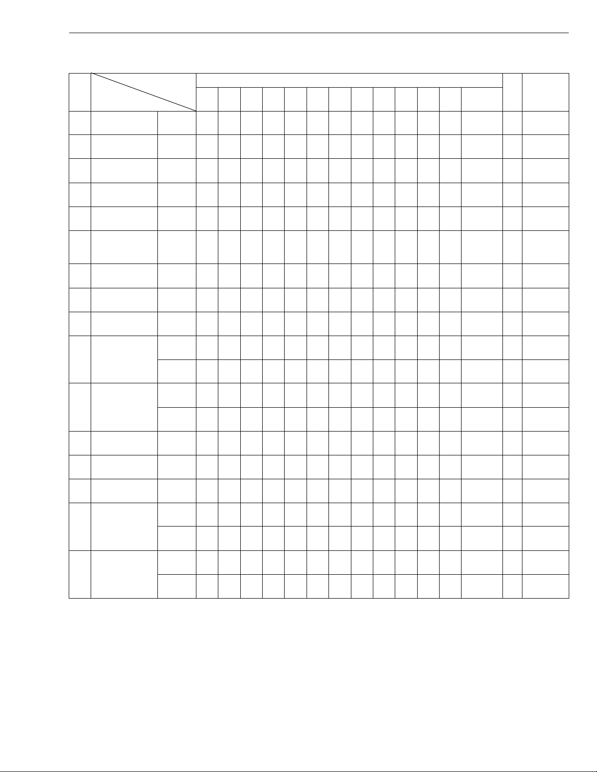
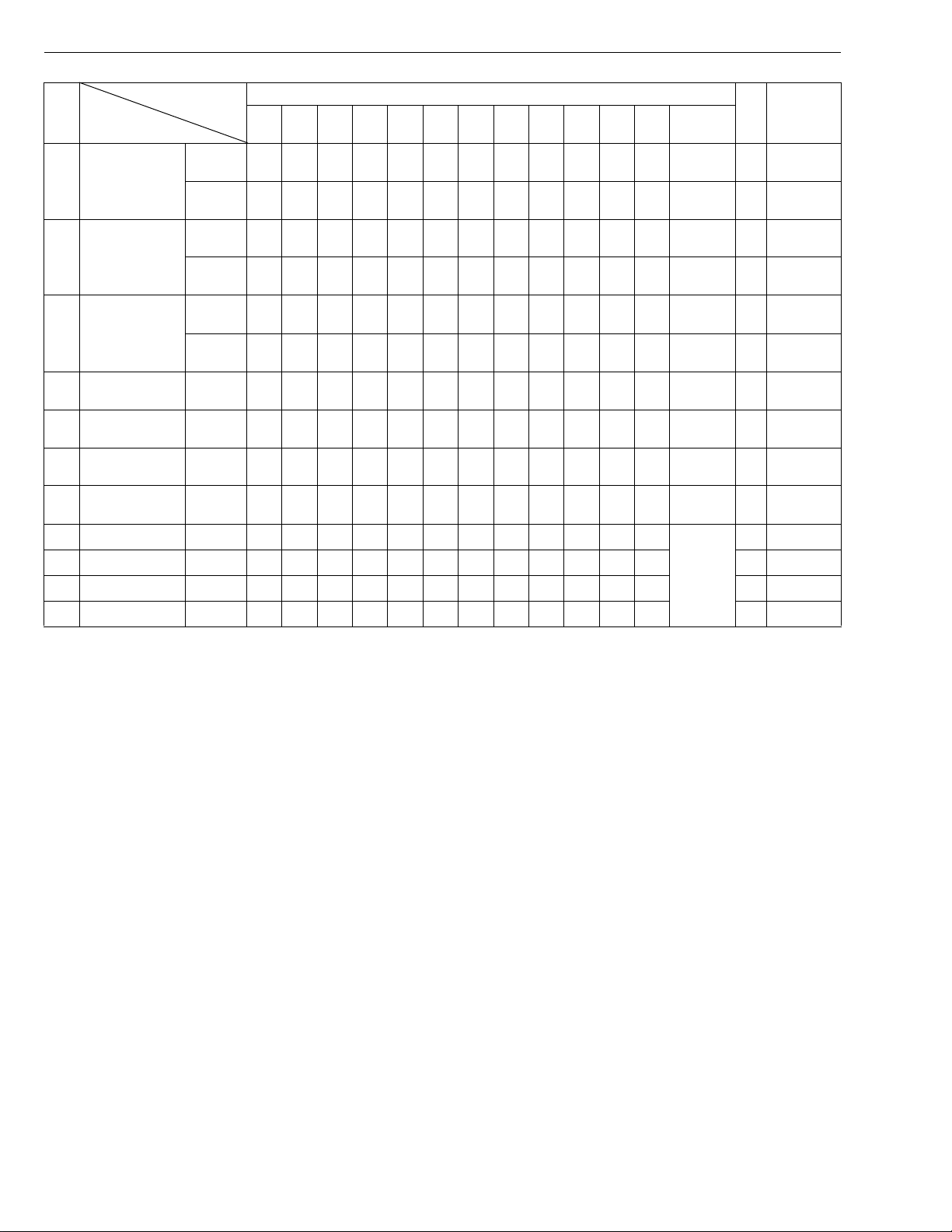
6. MAINTENANCE CHECK LIST
G GENERAL
Period
No.
Items
1 Engine oil Change ★✩✩✩✩✩✩
2 Engine oil filter Replace ★✩✩✩
Transmission
3
fluid
Transmission oil
4
filter
Transmission
5
strainer
Rear axle gear
6
case (RH & LH)
fluid
7 Front axle pivot Adjust ★✩✩✩
8 Safety device Check ✩✩✩✩✩✩✩✩✩✩✩✩
Greasing
9
(without mower)
Mower gear box
10
oil
Air cleaner
11
element
12 Battery condition Check ✩✩✩✩✩✩
13 Fan belt Adjust ✩✩✩✩✩✩
14 Parking brake Adjust ✩✩✩✩✩✩
Fuel filter
15
element
16 Fuel line
Change ★✩✩
Replace ★✩✩✩
Clean ★✩✩
Change ★✩✩
Check ✩✩✩✩✩✩✩✩✩✩✩✩
Change ✩✩✩✩
Clean ✩✩✩✩✩✩✩✩✩✩✩✩
Replace
Check ✩✩✩✩✩✩
Replace ✩
Check ✩✩✩✩✩✩
Replace
50 100 150 200 250 300 350 400 450 500 550 600
– ✩✩✩✩✩✩✩✩✩✩✩✩
Service interval
After
since
every
100 hr
every
200 hr
every
200 hr
every
200 hr
every
200 hr
every
200 hr
every
200 hr
every
50 hr
every
50 hr
every
150 hr
every
150 hr
every
50 hr
every
1 year
every
100 hr
every
100 hr
every
100 hr
every
100 hr
every
400 hr
every
100 hr
every
2 years
*1 G-26
Reference
page
G-17
G-18
G-21
G-18
G-20
G-21
G-19
G-22
G-24
G-26
–
–
G-26
G-28
G-29
G-28
G-33
G-28
–
W1037757
• The jobs indicated by ★ must be done initially.
1
*
Suggested cleaning interval is every 100 hours in normal conditions.
This maintenance should be done daily more often in dusty condition than in normal conditions.
G-11
Page 25
ZD21N-EC, ZD21-EC, ZD28-EC, WSM
KiSC issued 09, 2006 A
G GENERAL
Period
No.
Items
Radiator hose
17
and clamp
18 Hydraulic hose
19 Intake air line
Motion control
20
lever pivot
21 Radiator Clean
22 Coolant Change
Mower gear box
23
oil seal
24 Fuel system Bleed
25 Fuse Replac e G-37
26 Blade Replace G-38
27 Mower belt Replace G-38
Check ✩✩✩
Replace
Check ✩✩✩
Replace
Check ✩✩✩
Replace
Adjust ✩✩✩
Replace
50 100 150 200 250 300 350 400 450 500 550 600
Service interval
After
since
every
200 hr
every
2 years
every
200 hr
every
2 years
every
200 hr
every
2 years
every
200 hr
every
1 year
every
1 year
every
2 years
Service
as
required
Reference
page
G-31
G-31
G-32
*2
G-32
G-34
G-34
G-36
G-38
W1063926
–
–
–
■ IMPORTANT
2
Replace if necessary.
*
G-12
Page 26

ZD21N-EC, ZD21-EC, ZD28-EC, WSM
KiSC issued 09, 2006 A
G GENERAL
7. CHECK AND MAINTENANCE
CAUTION
• Be sure to check and service the machine o n a flat place with en gine shut off, the pa rking brake on and
chock the wheels.
[1] DAILY CHECK
To prevent trouble from occurring, it is important to know the condition of the machine. Check the following items
before starting.
Checking
• Check areas where previous trouble was experienced.
• Walk around the machine.
1. Tire pressure, wear and damage
2. Oil and water leak
3. Engine oil level
4. Transmission fluid le vel
5. Coolant level in the recovery tank
6. Damage of machine body, tightness of all bolts and nuts
7. Radiator screen
8. Panel screen
9. Brake play
10.Air cleaner
11.Fuel level
12.Oiling
•Mower
1. Oil leak
2. Make sure blade cap screws are tight.
3. Check blades for wear or damage.
4. Check all hardwar e.
5. Make sure all pins are in place.
6. Mower deck cleaning
7. Greasing
• While sitting in the operator’s seat,
1. Motion contr ol lever
2. Parking brake
• Turning the key switch “ON”
1. Performance of the easy checker light
• Starting the engine,
1. Color of the exhaust fumes
2. Safety start switch, seat safety control and another safety control and another safety devices.
3. Check for abnorma l nois e and vi br ati on.
G-13
Page 27
ZD21N-EC, ZD21-EC, ZD28-EC, WSM
■
IMPORTANT■
KiSC issued 09, 2006 A
G GENERAL
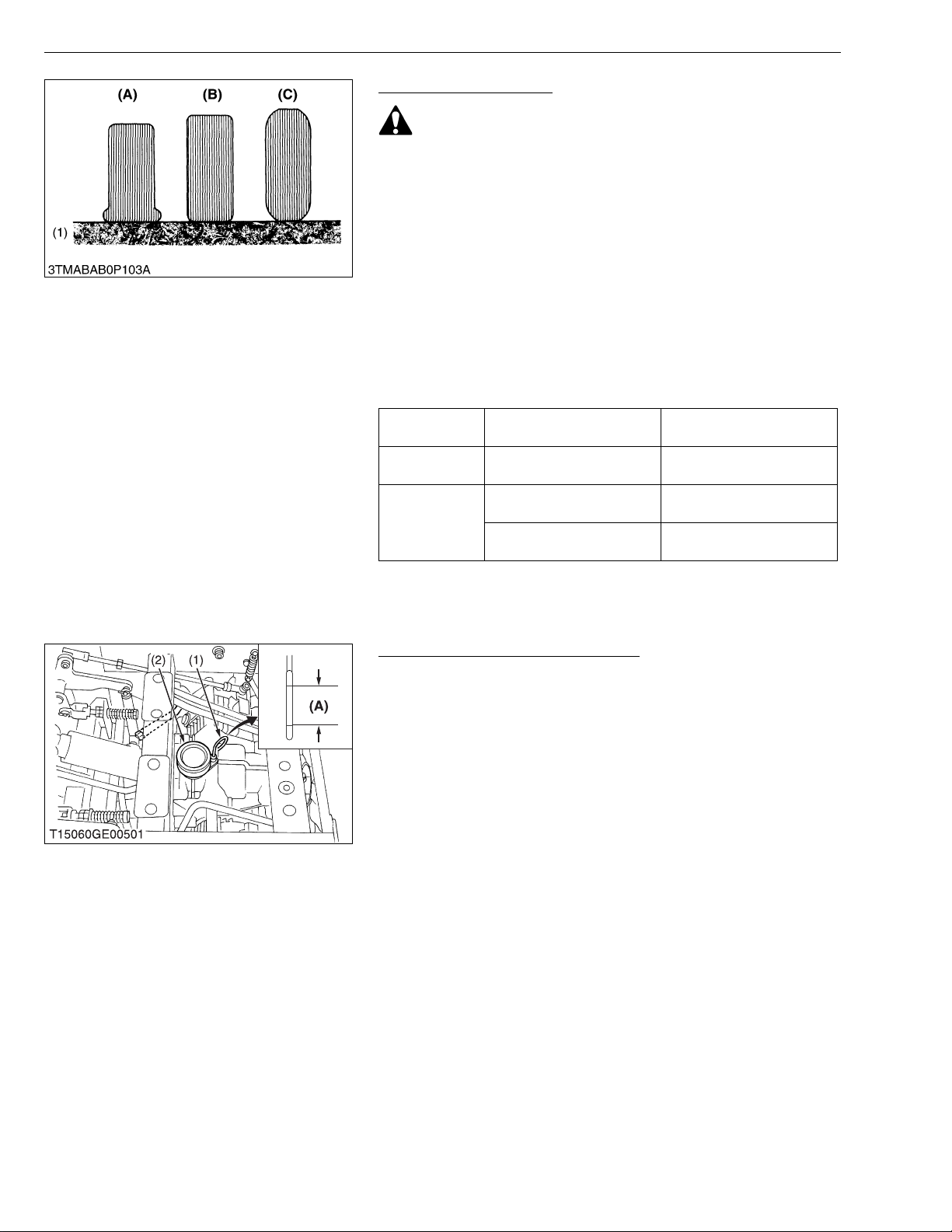
Checking Tire Pressure
WARNING
To avoid personal injury:
• Do not attempt to mount a tire on a rim. This should be done
by a qualified person with the proper equipment.
• Always maintain the correct tire pressure.
Inflation pressure in front tires rises quickly when using
compressed air.
Do not inflate tires above the r ecommended pressure shown
in the Operator’s Manual.
IMPORTANT
• Do not use tires larger than specified.
■ Inflation Pressure
Though the inflation pressure is factory-set to the prescribed
level, it naturally drops slowly in the cours e of time. Thus, check it
and inflate as necessary.
Tire Sizes
Front 15 × 6.0-6, 4PR Rib
23 × 10.5-12, 4PR Turf
Rear
24 × 12.0-12, 4PR Turf
Recommended Inflation
Pressure
207 kPa
2
140 kPa
2
140 kPa
2
, 30 psi)
, 20 psi)
, 20 psi)
(2.1 kgf/cm
(1.4 kgf/cm
(1.4 kgf/cm
(1) Ground (A) Insufficient
(B) Normal
(C) Excessive
W1041550
Checking Transmission Fluid Level
1. Park the mach ine on a flat surface, lower the imp lement to the
ground and shut off engine and remove the key.
2. Raise and lock the operator’s seat.
3. To check the oil level, draw out the dipstick, wipe it clean, replace
it, and draw it out again. Check to see that the oil level lies
between the two not ches. If the level is to o low, add ne w oil to
the prescribed level at the oil inlet.
(See page G-7.)
• If oil level is low, do not run engine.
(1) Oil Level Dipstick
(2) Oil Plug and Breather Cup
(A) Oil level is acceptable within this
range.
W1041984
G-14
Page 28
ZD21N-EC, ZD21-EC, ZD28-EC, WSM
■
KiSC issued 09, 2006 A
G GENERAL
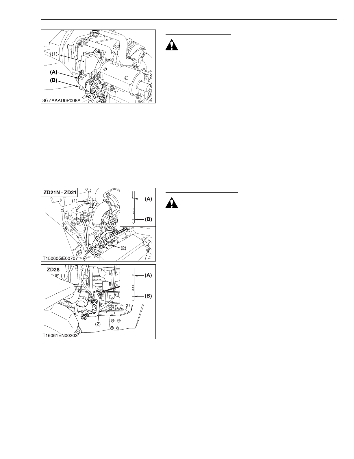
Checking Coolant Level
CAUTION
To avoid personal injury:
• Do not remove the radiator cap when the engine is hot. Then
loosen cap slightly to the stop to relieve any excess
pressure before removing cap completely.
1. Check to see t hat the coola nt level is b etween the “FULL” and
“LOW” marks of recovery tank.
2. When the coolant level drops due to evaporation, add water only
up to the full level of the recovery tank.
In case of leaka ge, add anti-freeze and water in the specified
mixing ratio up to the full level.
(See page G-7.)
IMPORTANT
• If the radiator cap has to be removed, follow the caution
above and securely retighten the cap.
• Use clean, distilled water a nd anti-freeze t o fill the r ecovery
tank.
(1) Recovery Tank (A) FULL
(B) LOW
W1042377
Checking Engine Oil Level
CAUTION
To avoid personal injury:
• Always stop the engine and remove the key before checking
oil.
1. Check engine oil before starti ng and 5 minut es or more afte r the
engine has stopped.
2. Wipe dipstick area clean.
3. To check the oil level, remove the dipstick, wipe it clean, replace
it, and draw it out again. Check to see that the oil level is between
the two notches.
4. Add new oil to the prescribed level at the oil port if necessary.
5. When using a different brand or viscosity oil from the previous
one, remove all of the old oil and oil filter. Never mix two different
types of oil.
6. Use the proper Engine Oil SAE according to the ambient
temperatures. (See page G-7.)
(1) Engine Oil Port
(2) Oil Level Dipstick
(A) Upper Level
(B) Lower Level
W1042659
G-15
Page 29
ZD21N-EC, ZD21-EC, ZD28-EC, WSM
■
KiSC issued 09, 2006 A
G GENERAL
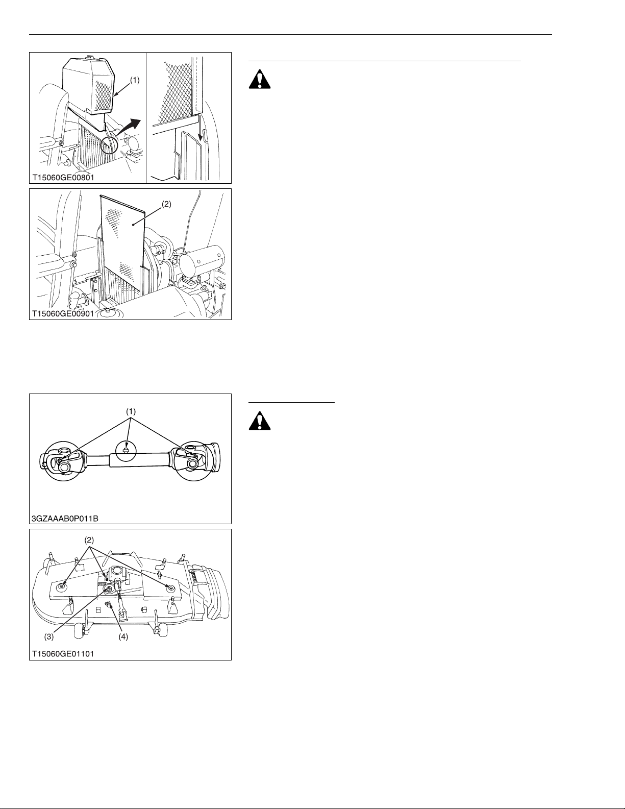
Checking and Cleaning Radiator to Prevent Overheating
CAUTION
To avoid personal injury:
• Be sure to stop the engine and remove the key before
cleaning.
Daily or after every 5 hour s of operation, check to be sure the
radiator screen and radiator core are clean. Dirt or chaff on the
radiator screen or radiator core decrease cooling performance.
1. Remove the radiator screen and panel sc reen and remo ve all
foreign material.
2. Remove the dust from between the fins and the tube.
3. Tighten the fan drive belt as necessary. For this, refer to “EVERY
100 HOURS” in Maintenance section.
4. If scale forms in the tube, clean with the scale inhibitor or its
equivalent.
5. Each time the panel screen is covered with grass during
operation, rub i t off the screen with hand. Check the radiator
screen from time to time if grass accumulates.
6. If the dust or chaff h as acc umula ted inside of the panel , remove
the radiator screen and clean inside completely.
After cleaning, replace the radiator screens properly.
NOTE
• When assembling the panel screen, be sure to fit it in the
runners.
(1) Panel Screen (2) Radiator Screen
W1043048
Greasing (Mower)
CAUTION
To avoid personal injury:
• Be sure to stop the engine and remove the key before
greasing.
1. Apply grease to the following position as figures.
(1) Mower Universal Joint
(2) Spindle Shaft
(3) Belt Tension Pulley
(4) Belt Tension Pivot
W1043490
G-16
Page 30
ZD21N-EC, ZD21-EC, ZD28-EC, WSM
■
KiSC issued 09, 2006 A
[2] CHECK POINTS OF INITIAL 50 HOURS
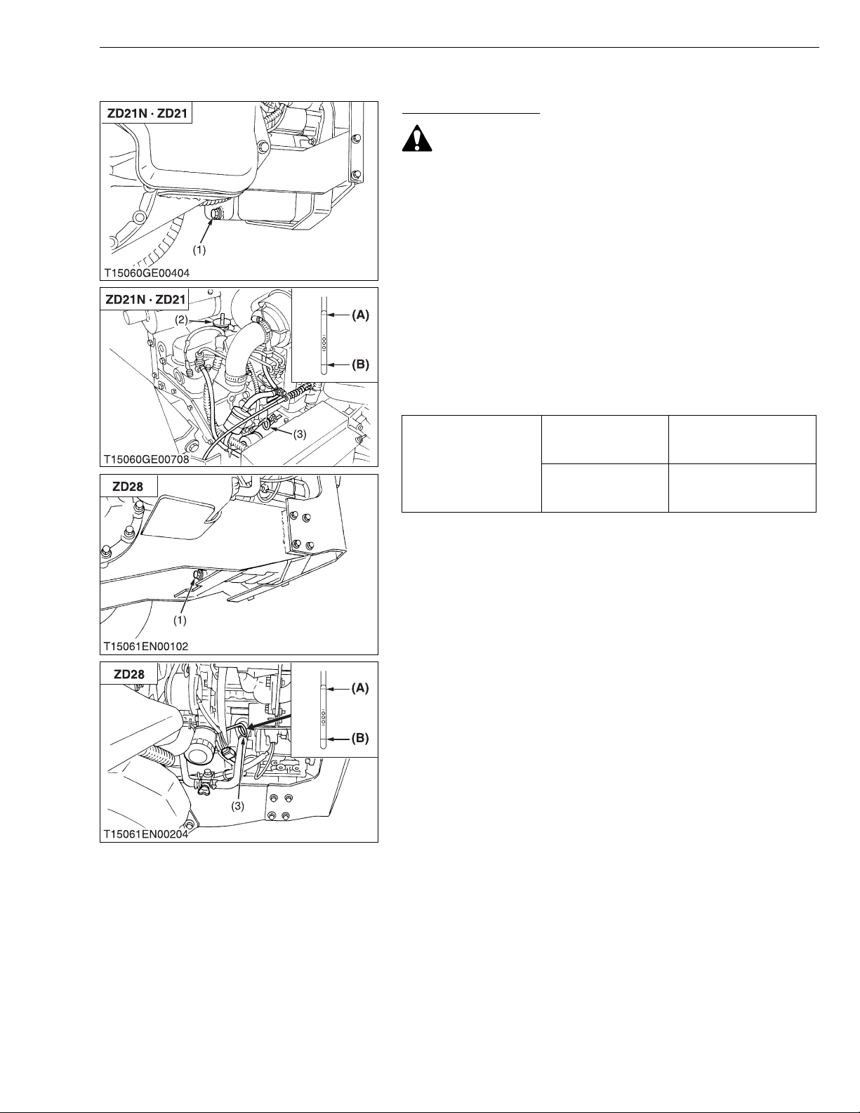
Changing Engine Oil
CAUTION
• Be sure to stop the engine before changing oil.
1. Start and warm up the engine for approx. 5 minutes.
2. Place an oil pan underneath the engine.
3. To drain the used o il, r emove the drai n plug (1) at t he botto m of
the engine and drain the oil completely.
4. Screw in the drain plug (1).
5. Fill new oil up to upper line on the dipstick (3).
IMPORTANT
• When using an oil of different manufacture or viscosity from
the previous one, remove all of the old oil.
• Never mix two different type of oil.
• Use the proper SAE engine oil according to ambient
temperatures.
Refer to “LUBRICANTS, FUEL AND COOLANT”.
(See page G-7.)
Engine oil capacity
ZD21N
ZD21
ZD28
G GENERAL
3.5 L
3.7 U.S.qts.
3.1 Imp.qts.
3.4 L
3.6 U.S.qts.
3.0 Imp.qts.
(1) Drain Plug
(2) Oil Inlet Plug
(3) Dipstick
(A) Upper Level
(B) Lower Level
W1030749
G-17
Page 31
ZD21N-EC, ZD21-EC, ZD28-EC, WSM
■
IMPORTANT■
KiSC issued 09, 2006 A
G GENERAL
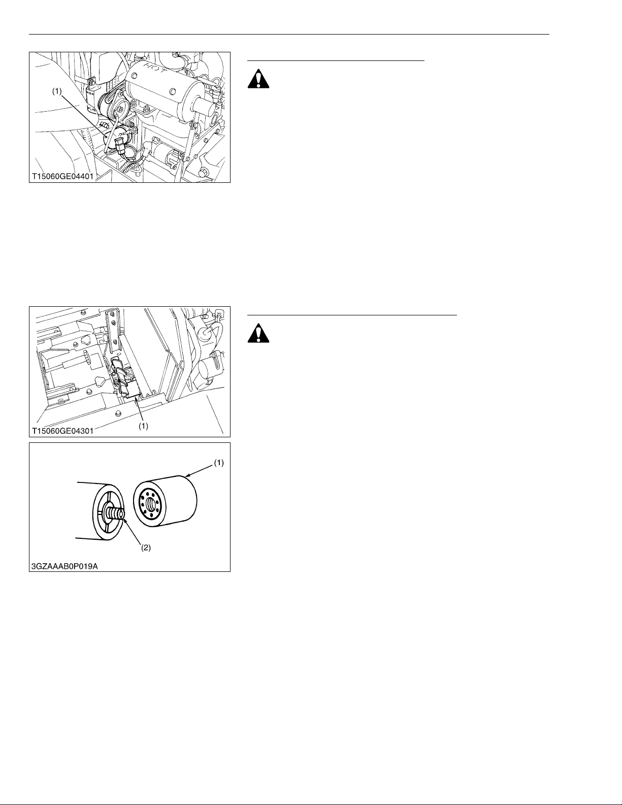
Replacing Engine Oil Filter Cartridge
CAUTION
• Be sure to stop the engine before changing the oil filter
cartridge.
• Allow engine to cool down sufficiently, oil can be hot and
may cause burns.
1. Remove the engine oil filter cartridge (1) with the filter wrench.
2. Apply a slight coat of oil onto the rubber gasket of new cartridge.
3. To install the new cartridge, screw it in by hand. Over tightening
may cause deformation of rubber gasket.
4. After the cartridge has been replaced, the engine oil level
normally lowers a little. Add engine oil to proper level. Check for
oil leaks around filter gasket.
IMPORTANT
• To prevent serious damage to the engine, element of
recommended type must be used. Use only a genuine
KUBOTA filter or its equivalent.
(1) Engine Oil Filter Cartridge
W1030949
Replacing Transmission Oil Filter Cartridg e
CAUTION
• Be sure to stop the engine before changing the oil filter
cartridge.
• Allow transmission case to cool down sufficiently; oil can be
hot and may cause burns.
1. The oil filter cartridge must be changed every 300 service hours.
2. Remove the oil filter cartridge with the filter wrench.
3. Lightly tighten the screw (2) by using a screwdriver.
4. Apply a slight coat of oil onto the cartridge gasket.
5. To install the new cartridge, screw it in by hand.
Over tightening may cause deformation of rubber gasket.
6. After the new cartridge has been replaced, the transmission fluid
level normally lowers a little. Add fluid to proper level. Check for
oil leaks around filter gasket.
• To prevent serious damage to hydraulic system, the
replacement filter must be a highly efficient, 10 μm filter.
Use only a genuine KUBOTA filter or its equivalent.
(1) Transmission Oil Filter Cartridge (2) Screw
W1031068
G-18
Page 32
ZD21N-EC, ZD21-EC, ZD28-EC, WSM
NOTE■
KiSC issued 09, 2006 A
[3] CHECK POINT OF INITIAL 100 HOURS
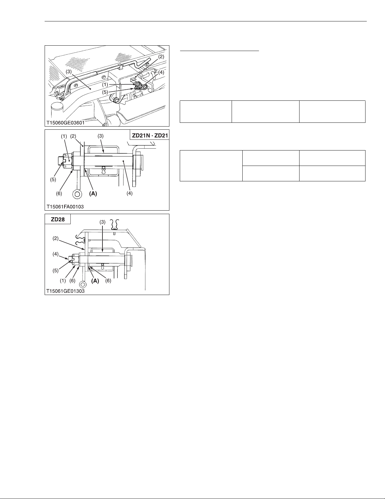
Adjusting Front Axle Pivot
1. Lift up and securely block the front of the machine.
2. Measure the clearance (A) between the front axle (3) and front
axle support (2).
3. If the measurement exceed s the allowable limi t, remove the set
spring (5) and adjust the end play by slotted nut (1).
(When reassembling)
Tightening torque
• When fastening the center pin (4), tighten the nut (1) so that
the front axle maybe oscillated smoothly by hand.
Front axle end play (A)
Center pin lock nut
(Slotted nut)
Factory spec.
Allowable limit
G GENERAL
40 to 80 N·m
4.08 to 8.16 kgf·m
29.50 to 59.00 ft-lbs
0 to 0.2 mm
0 to 0.008 in.
0.5 mm
0.02 in.
(1) Slotted Nut
(2) Front Axle Support
(3) Front Axle
(4) Center Pin
(5) Set Spring
(A) Front Axle End Play
W1053511
G-19
Page 33
ZD21N-EC, ZD21-EC, ZD28-EC, WSM
■
■
KiSC issued 09, 2006 A
[4] CHECKING POINTS OF INITIAL 200 HOURS
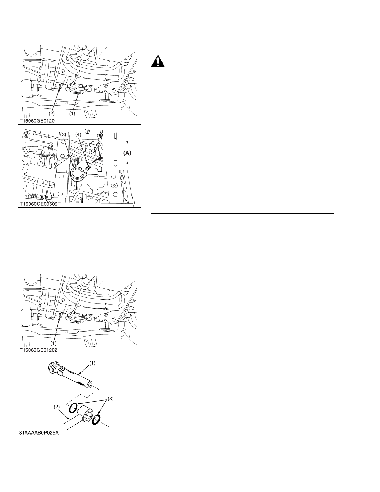
Changing Transmission Fluid
CAUTION
• Be sure to stop the engine before changing the transmission
fluid.
1. Place an oil pan underneath the transmission case.
2. Remove the drain plugs (1) at the bottom of the transmission
case and drain the oil completely.
3. After draining, screw in the drain plug.
4. Fill new oil from filling port after removing the filling plug (3) up to
the upper notch on the dipstick.
5. After running the engine for a few minutes, stop it and check the
oil level again, if low, add oil to prescribed level.
IMPORTANT
• Use only multi-grade transmission oil. Use of other oils may
damage the transmission or hydraulic system.
Refer to “LUBRICANTS, FUEL AND COOLANT”. (See page
G-7.)
• Never work the machine immediately after changing the
transmission oil. Keeping the engine at medium speed for a
few minutes prevents damage to the transmiss ion.
• Do not mix different brands oil together.
Transmission fluid capacity
G GENERAL
4.0 L
4.2 U.S.qts.
3.5 Imp.qts.
(1) Drain Plug
(2) Transmission Strainer
(3) Oil Plug and Breather Cup
(4) Dipstick
(A) Oil level acceptable within this
range.
W1048918
Cleaning Transmission Strainer
When changing the transmission fluid, disassemble and rinse the
strainer with nonflammable solvent to completely clean off filings.
Check O-rings (3), replace if damaged, cracked or hardened.
When reassembling be careful not to damage the parts.
NOTE
• Since the fine filings in the oil can damage the precision
component parts of the hydraulic system, the end of the
suction line is provided with an oil strainer.
(1) Strainer
(2) Suction Line
(3) O-ring
W1049356
G-20
Page 34
ZD21N-EC, ZD21-EC, ZD28-EC, WSM
■
KiSC issued 09, 2006 A
G GENERAL
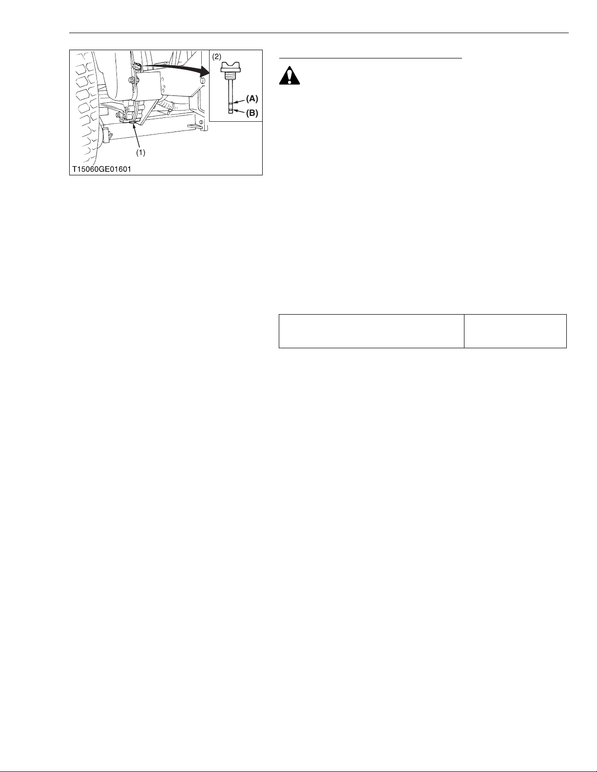
Changing Rear Axle Case Oil (RH & LH)
CAUTION
• Be sure to s top the engine be fore ch anging t he transm ission
fluid.
1. Place an oil pan underneath the rear axle gear case.
2. Remove the drain plugs (1) at the bottom of the transmission
case and drain the oil completely.
3. After draining, screw in the drain plug.
4. Fill new oil from filling port after removing the filling plug (2) up to
the upper line of the gauge.
5. After running the engine for a few minutes, stop it and check the
oil level again, if low, add oil to prescribed level.
IMPORTANT
• Use only multi-grade transmission oil. Use of other oils may
damage the transmission or hydraulic system.
Refer to “LUBRICANTS, FUEL AND COOLANT”. (See page
G-7.)
• Never work the machine immediately after changing the
transmission oil. Keeping the engine at medium speed for a
few minutes prevents damage to the transmission.
• Do not mix different brands oil together.
Rear axle case oil capacity
1.8 L each
1.9 U.S.qts. each
1.6 Imp.qts. each
(1) Drain Plug
(2) Filling Plug with Gauge
(A) Upper Level
(B) Lower Level
W1049491
G-21
Page 35
ZD21N-EC, ZD21-EC, ZD28-EC, WSM
IMPORTANT■
KiSC issued 09, 2006 A
[5] CHECK POINTS OF EVERY 50 HOURS
Checking Safety Device
CAUTION
To avoid personal injury:
• Do not allow anyone near the machine while testing.
• If the machine does not pass one of the following tests, do
not operate the machine.
• Sit on operator’s seat for all tests except for Test 1.
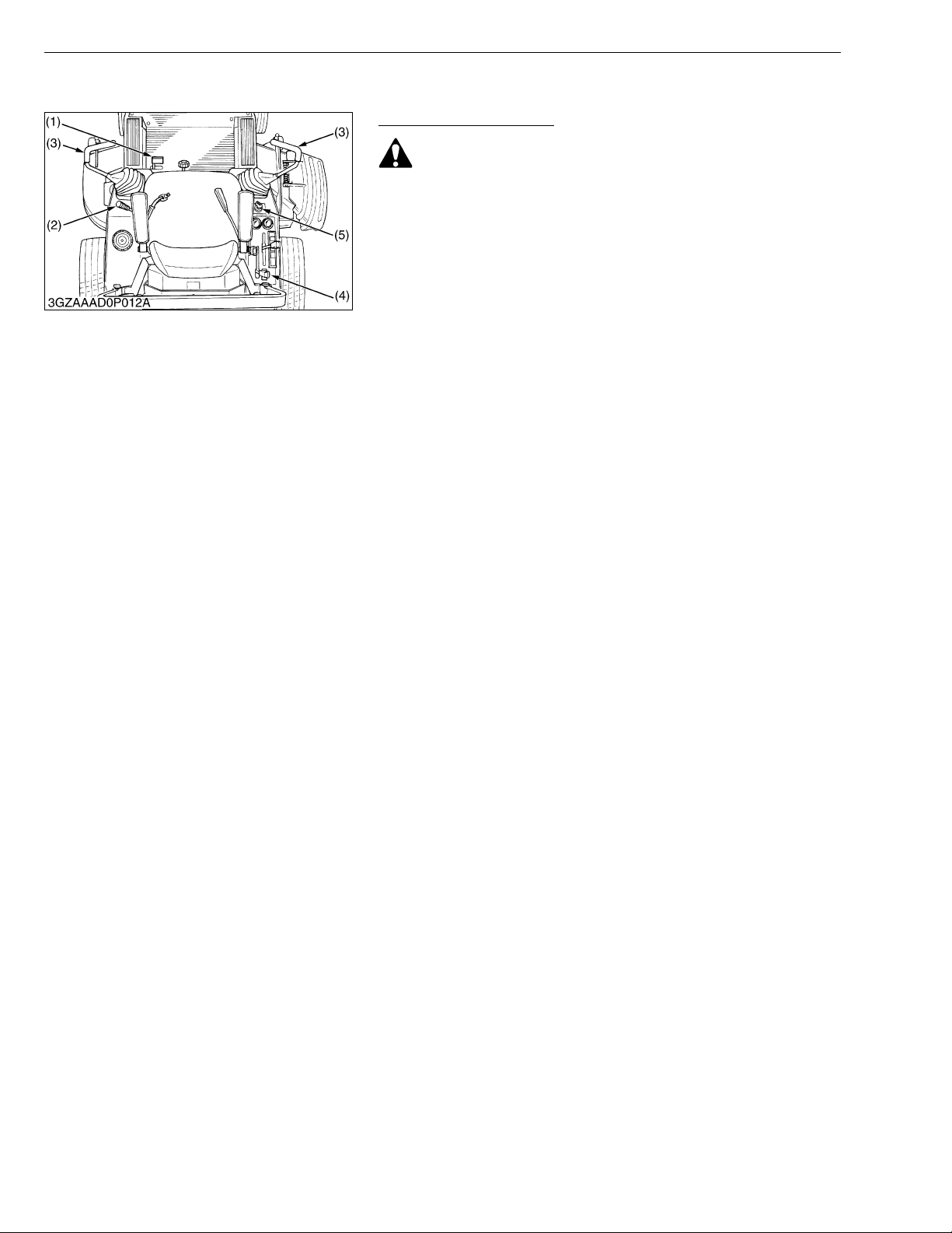
■ Test 1 (OPERATOR NOT ON THE SEAT)
1. Securely set the parking brake.
2. Shift the PTO lever (4) to “DISENGAGE” (OFF) position.
3. Set the motion control levers (3) to the “NEUTRAL LOCK”
position.
4. Turn the key switch (5) to “START” position.
5. The engine must not crank.
■ Test 2 (OPERATOR ON THE SEAT)
1. Do not set the parking brake. (Release it from test 1.)
2. Shift the PTO lever (4) to “DISENGAGE” (OFF) position.
3. Set the motion control levers (3) to the “NEUTRAL LOCK”
position.
4. Turn the key switch (5) to “START” position.
5. The engine must not crank.
■ Test 3 (OPERATOR ON THE SEAT)
1. Securely set the parking brake.
2. Shift the PTO lever (4) to “DISENGAGE” (OFF) position.
3. Grasp the moti on control levers (3) an d move then inward from
“NEUTRAL LOCK” position to “NEUTRAL” positio n and then
release the levers.
4. Turn the key switch (5) to “START” position.
5. The engine must not crank.
■ Test 4 (OPERATOR ON THE SEAT)
1. Securely set the parking brake.
2. Shift the PTO lever (4) to “ENGAGE” (ON) position.
3. Grasp the moti on control levers (3) an d move then inward from
“NEUTRAL LOCK” position to “NEUTRAL” positio n and then
release the levers.
4. Turn the key switch (5) to “START” position.
5. The engine must not crank.
■ Test 5 (OPERATOR ON THE SEAT)
1. Start the engine.
2. Keeps the parking brake securely set.
3. Shift the PTO lever (4) to “DISENGAGE” (OFF) position.
4. Grasp the moti on control levers (3) an d move then inward from
“NEUTRAL LOCK” position to “NEUTRAL” positio n and then
release the levers.
5. The engine must shut off after a short time delay.
G GENERAL
• For this test only, the engine will shut off in a few seconds.
(1) Parking Brake Lock Pedal
(2) Parking Brake Release Lever
(3) Motion Control Lever
(4) PTO Lever
(5) Key Switch
G-22
Page 36
ZD21N-EC, ZD21-EC, ZD28-EC, WSM
KiSC issued 09, 2006 A
G GENERAL
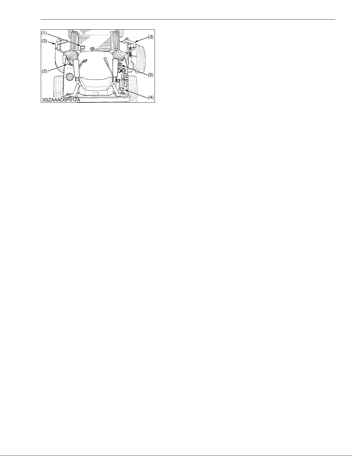
■ Test 6 (OPERATOR ON THE SEAT)
1. Start the engine.
2. Do not set the parking brake.
3. Shift the PTO le ve r (4) to “DISENGAGE” (OFF) position.
4. Grasp the mot ion control levers (3) a nd move t hen inward from
“NEUTRAL LOCK” position to “NEUTRAL” position and then
release the levers.
5. Stand up. (Do not get off the machine.)
6. The engine must shut off.
■ Test 7 (OPERATOR ON THE SEAT)
1. Start the engine.
2. Do not set the parking brake.
3. Shift the PTO le ve r (4) to “ENGAGE” (ON) position.
4. Stand up. (Do not get off the machine.)
5. The engine must shut off.
(1) Parking Brake Lock Pedal
(2) Parking Brake Release Lever
(3) Motion Control Lever
(4) PTO Lever
(5) Key Switch
W1032761
G-23
Page 37
ZD21N-EC, ZD21-EC, ZD28-EC, WSM
KiSC issued 09, 2006 A
G GENERAL
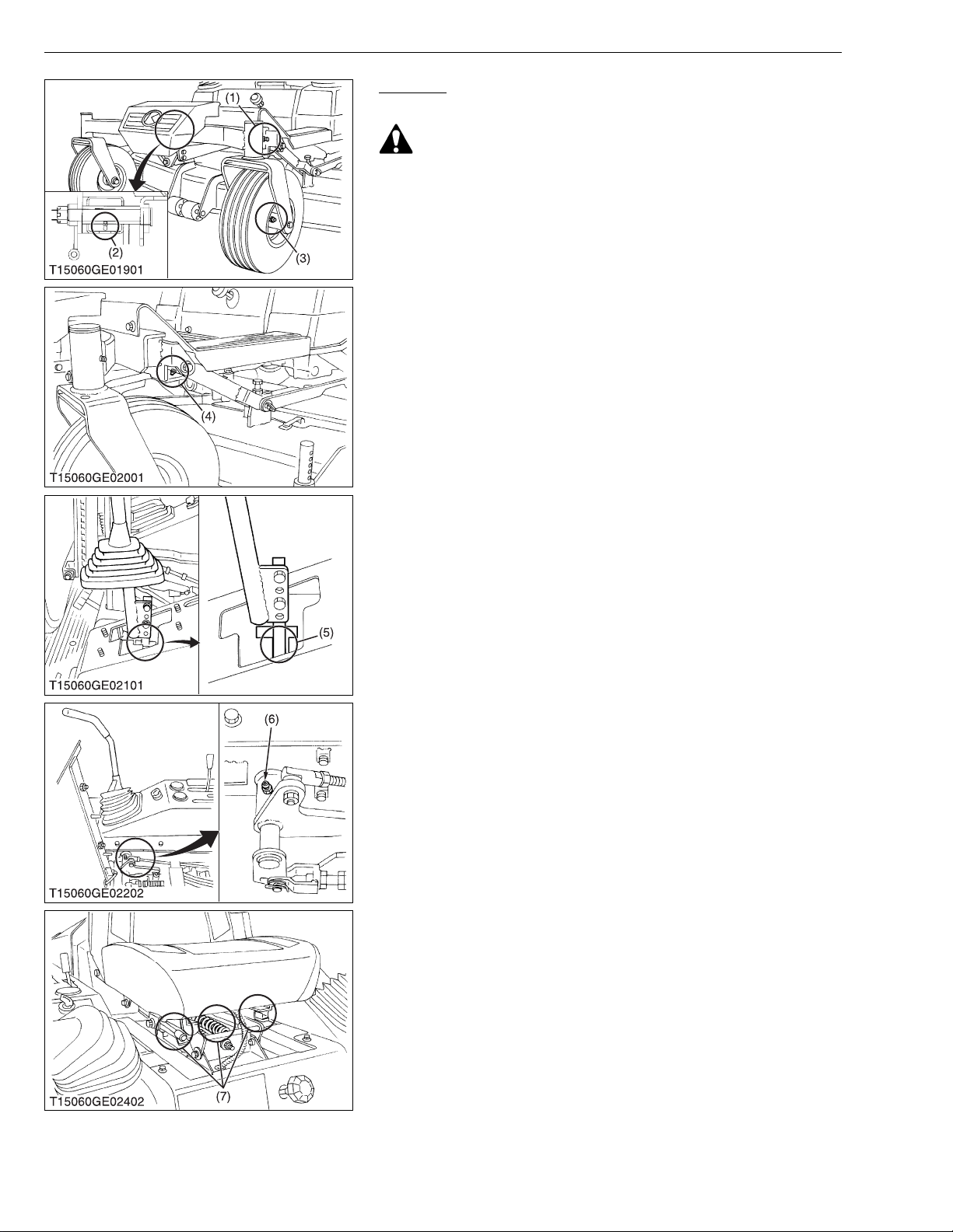
Greasing
1. Apply a grease to the following position as figures.
CAUTION
To avoid personal injury:
• Be sure to stop the engine and remove the key before
greasing.
(1) King Pin (LH · RH)
(2) Center Pin
(3) Front Wheel (LH · RH)
(4) Front Lift Arm (LH · RH)
(5) Motion Control Levers (LH · RH)
(6) Motion Control Lever Boss
(LH · RH)
(7) Seat Adjuster
W1034228
G-24
Page 38
ZD21N-EC, ZD21-EC, ZD28-EC, WSM
KiSC issued 09, 2006 A
G GENERAL
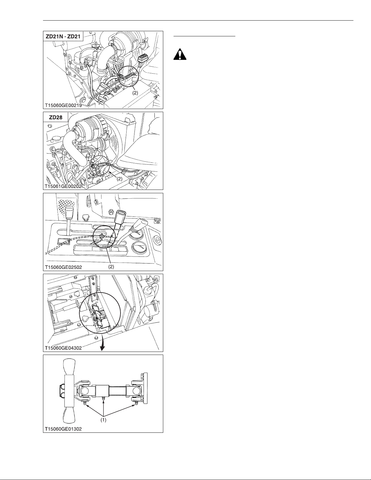
Greasing (Continued)
1. Apply a grease to the following position as figures.
CAUTION
To avoid personal injury:
• Be sure to stop the engine and remove the key before
greasing.
(1) Machine Universal Joint (2) Throttle Cable (Oil)
W1035206
G-25
Page 39
ZD21N-EC, ZD21-EC, ZD28-EC, WSM
NOTE■
KiSC issued 09, 2006 A
G GENERAL
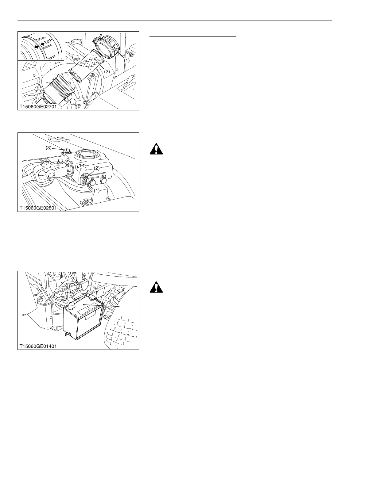
Cleaning Air Cleaner Element
1. The air cleaner uses a dry element, never apply oil.
2. Do not touch the filter element except where cleaning is required.
To clean the elemen t, use cle an and dry co mpress ed air on the
inside of the eleme nt. Air pres sure shou ld not exce ed 205 kPa
2
(2.1 kgf/cm
, 30 psi).
• Operating in dusty conditions requires more frequent
maintenance.
• Align the arrow marks when reinstalling the air cleaner
cover.
(1) Air Cleaner Cover (2) Air Cleaner Element
W1053698
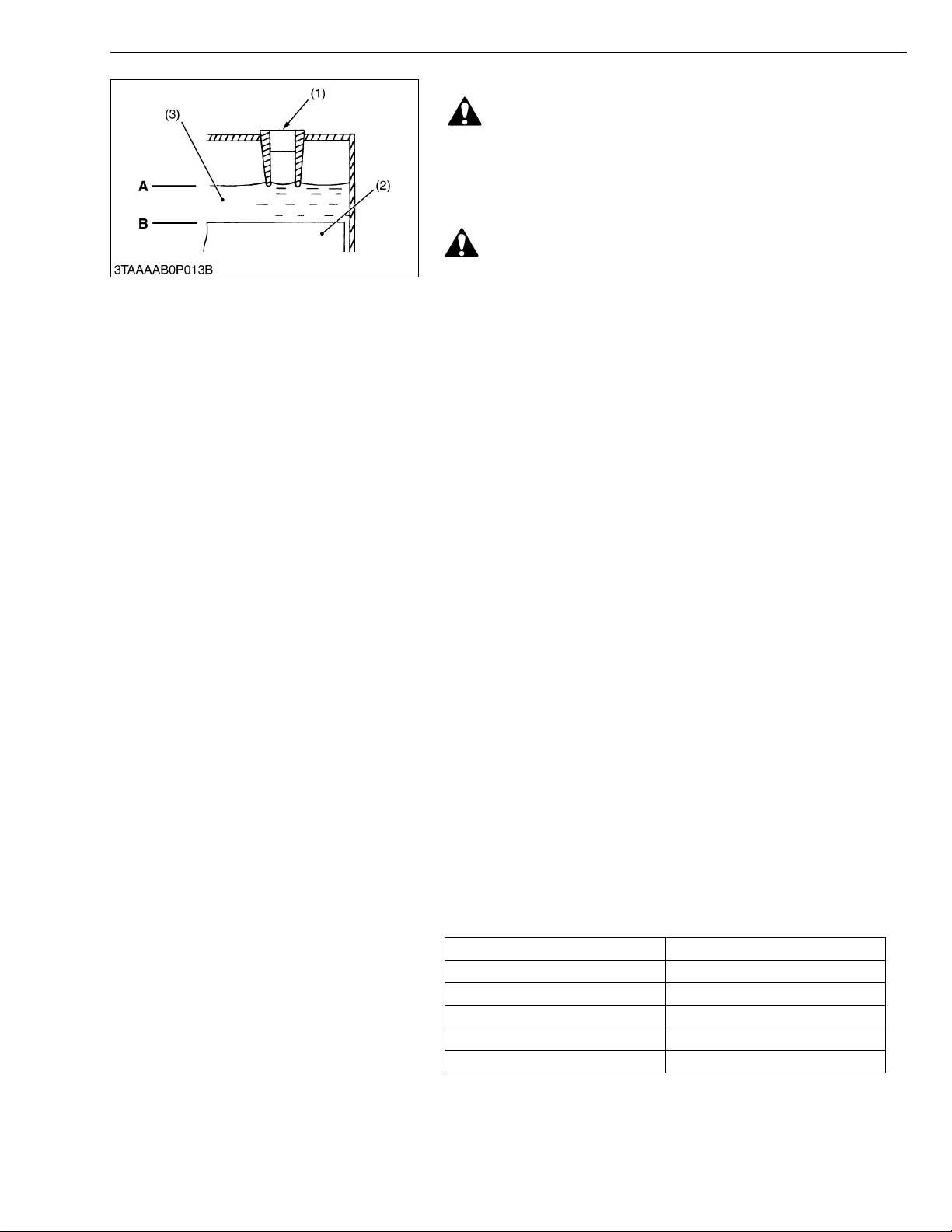
Checking Gear Box Oil Level
CAUTION
To avoid personal injury:
• Always stop the engine and remove the key before checking
oil.
1. Park the machin e on a flat surface and lower the mower to the
ground.
To check the o il level, loosen che ck plug bolt an d check to see
that the oil level is just below the check plug port.
If the level is too low, add new oil to the prescribed level at the oil
inlet.
(See page G-7.)
(1) Drain Plug (Bolt)
(2) Check Plug (Bolt)
(3) Oil Filler Plug
W1054012
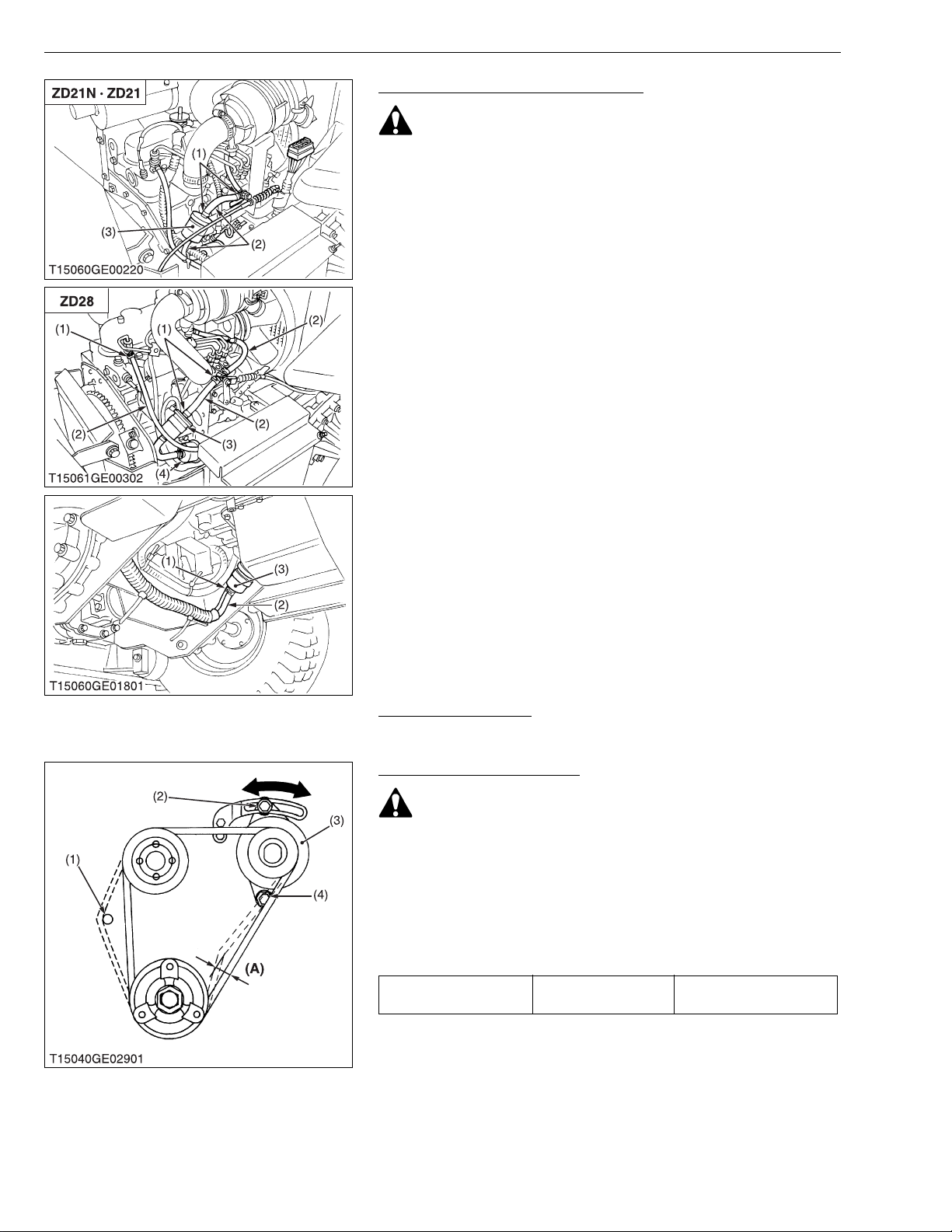
[6] CHECK POINTS OF EVERY 100 HOURS
Checking Battery Condition
CAUTION
• Never remove the vent cap while the engine is running.
(1)
Keep electrolyte away from eye s, hand s and clot hes . If you
are spattered with it, wash it away completely with water
immediately and get medical attention.
• Wear eye protection and rubber gloves when working
around battery.
Mishandling the battery shortens the service life and adds to
maintenance costs.
The original battery is a maintenance-free, non accessible type
battery.
If the battery is weak, the engine wi ll be difficult to sta rt and the
lights will become dim. It is important to check the battery
periodically.
(1) Battery
W1083097
G-26
Page 40
ZD21N-EC, ZD21-EC, ZD28-EC, WSM
KiSC issued 09, 2006 A
G GENERAL
■ Battery Charging
DANGER
To avoid serious injury or death:
• When the battery is being activated, hydrogen and oxygen
gases in the battery are extremely explosive. Keep open
sparks and flames away from the battery at all times,
especially when charging the battery.
CAUTION
• When charging battery, ensure that the vent caps are
securely in place (if equipped).
• When disconnecting the cables from the battery, start with
the negative terminal first.
When connecting the cables to the battery, start with the
positive terminal first.
• Never check battery charge by placing a metal object across
the posts.
Use a voltmeter or hydrometer.
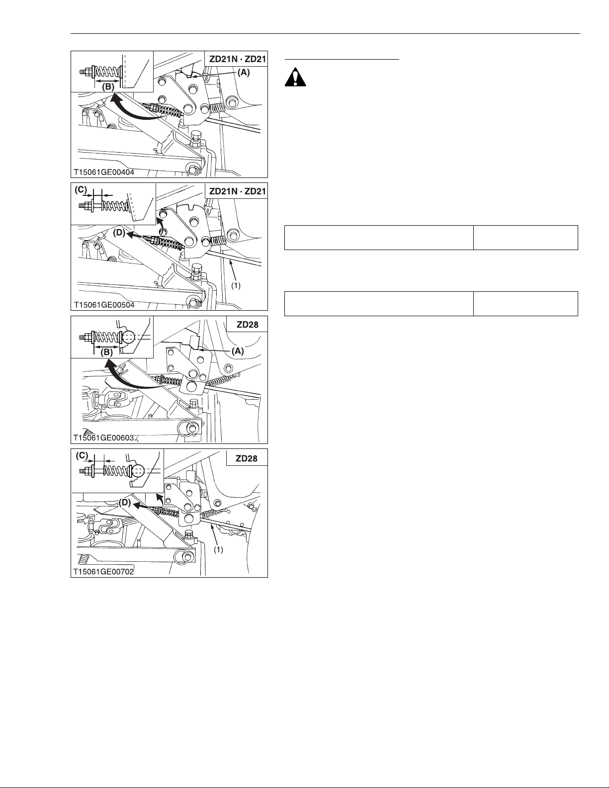
(For accessible main tainable t ype ba tteries w ith re movable v ent
caps.)
1. Make sure each ele ctr o ly te le ve l i s at th e bo ttom of ve nt wel ls, i f
necessary add distilled water in a well-ventilated area.
2. The water in the electrolyte evaporates during recharging. Liquid
shortage damages the battery. Exc essive liquid s pills over and
damages the machine body.
3. To slow charge the battery, connect the battery positive terminal
to the charger positive terminal and the negative to the negative,
then recharge in the standard fashion.
4. A boost charge is only for emergencies. It will partially charge the
battery at a higher rate and in a short time.
When using a boost-charged battery, it is necessary to recharge
the battery as soon as possible.
Failure to do this will shorten the battery’s service life.
5. When the specific gravity of electrolyte reaches 1.27 to 1.29,
charge has completed.
6. When exchanging an old battery with new o ne, use a b attery o f
equal specification shown in “SPECIFICATIONS”.
(For non-accessible maintenance-free type batteries.)
Maintenance-free, non-accessible batteries are designed to
eliminate the need to add water. Yet the volu me of electrolyte
above plates may even tually becom e depleted d ue to abnor mal
conditions such a s hi gh heat or imp roper reg ulator s etting . Use
a voltmeter to check the state of charge. (See reference chart to
determine if charging is necessary.)
Battery voltage Reference state of change
12.6 100 % (Full charge)
12.4 75 %
12.2 50 %
12.0 25 %
11.8 0 %
(1) Vent well
(2) Separator
(3) Electrolyte
G-27
(A) Highest Level
(B) Lowest Level
W1035046
Page 41
ZD21N-EC, ZD21-EC, ZD28-EC, WSM
■
IMPORTANT■
KiSC issued 09, 2006 A
G GENERAL
Checking Fuel Lines And Fuel Filter
CAUTION
• Be sure to stop the engine and remove the key when
attempting to make the following checks and changes.
• Never fail to check the fuel lines periodically. The fuel lines
are subject to wear and age. Fuel may leak out onto the
running engine, causing a fire.
The fuel line con nections should be checked annually o r every
100 service hours, whichever comes first.
1. The fuel lines is made of rubber and ages regardl ess of service
period.
2. If the fuel line and clamps are found damages or deteriorat ed,
replace them.
3. Check fuel filter, if it is clogged by debris, and replace it.
IMPORTANT
• When the fuel line is disconnected for maintenance or
repair, close both ends of the fuel line with a piece of clean
cloth or paper to prevent dust and dirt from entering. In
addition, particular care must be take n not to admit dust and
dirt into the fuel pump. Entrance of dust and dirt causes
malfunction of the fuel pump and injector components.
(1) Pipe Clamps
(2) Fuel Line
(3) Fuel Filter
(4) Fuel Pump
W1034725
Changing Engine Oil
1. See page G-17.
W1034674
Adjusting Fan Belt Tension
CAUTION
• Be sure to stop the engine and remove the key before
checking belt tension.
1. If the fan drive belt becomes loose, the engine may overheat.
2. To adjust, loosen bolts and turn the alternator to tighten the belt.
3. After adjustment, sec urel y tighten the bol ts.
Moderate belt tension:
The belt deflect app rox. 10 mm (0.4 in .) when the center of the
belt is depressed with finger pressure of 98 N (10 kgf, 22 lbs).
Fan belt tension (A) Factory spec.
Approx. 10 mm
0.4 in.
• When replacing fan belt, be careful not to catch it on the cap
under the water pump. See the illustration to the left.
(1) Cap
(2) Tension bolt
(3) Alternator
(4) Adjustment bolt
G-28
Page 42
ZD21N-EC, ZD21-EC, ZD28-EC, WSM
■
KiSC issued 09, 2006 A
G GENERAL
Checking Parking Brake
CAUTION
To avoid personal injury:
• Stop the engine and chock the wheels before checking or
adjusting.
• Park the machine on a hard and level surface.
IMPORTANT
• Wrong adjustment may cause machine damage.
■ Check
1. Place the motion control levers to “NEUTRAL LOCK” position.
2. Be sure to chock the rear wheels.
3. Apply the parking brake to the notch.
4. Check the length of the brake springs on both sides.
Proper brake spring length at the first notch (B)
56 mm
2.2 in.
5. Release the parking brake.
6. Pull the brake rod fully forward by hand and hold.
7. Check the brake spring play.
Proper brake spring play (C)
1.0 to 2.0 mm
0.04 to 0.08 in.
8. If these dimensions are not correct, adjust.
(1) Brake Rod (A) Notch
(B) Parking Brake Spring Length
(C) Brake Spring Play
(D) Pull the Brake Rod
G-29
Page 43
ZD21N-EC, ZD21-EC, ZD28-EC, WSM
NOTE■
KiSC issued 09, 2006 A
G GENERAL
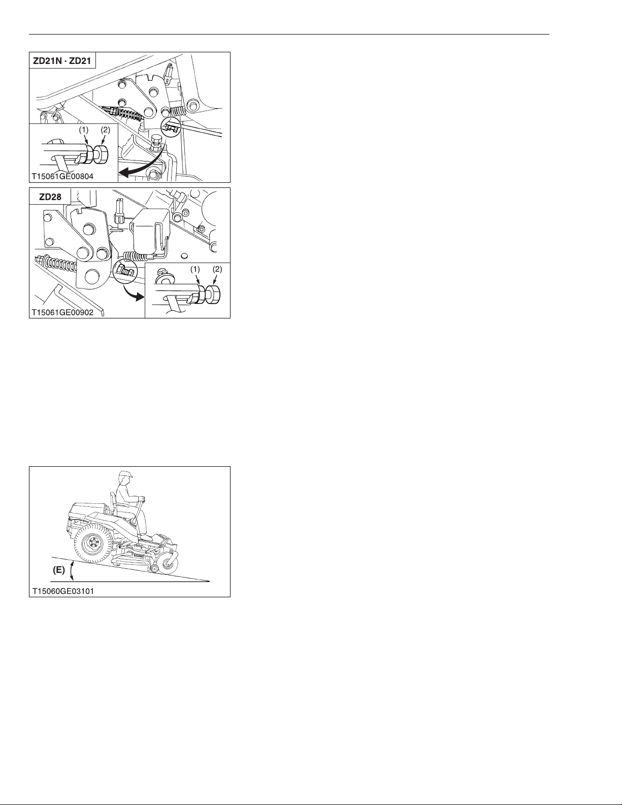
■ Adjustment of brake spring play
1. Place the motion control lever to “NEUTRAL LOCK” position.
2. Be sure to chock the rear wheels.
3. Release the parking brake.
4. Loosen the lock nuts.
5. Pull the brake rod fully forward by hand and hold.
6. Tighten the nut to the correct space between the end of the
spring and the plain washer.
7. Lock the nuts.
8. Adjust the other side spring to the same dimension.
■ Adjustment of brake length
1. Place the motion control lever to “NEUTRAL LOCK” position.
2. Apply the parking brake to the notch.
3. Loosen the lock nuts.
4. Adjust the spring length to the recommendation.
5. Lock the nuts.
6. Check the brake spring play to the recommendation.
If there is no play, adjust the brake spring play again.
7. Adjust the other side spring to the same dimension.
■ Check the play of parking brake lock pedal
1. Place the motion control levers to “NEUTRAL LOCK” position.
2. Be sure to chock the rear wheels.
3. Release the parking brake completely.
4. Check that pa rking brake rel ease lever moves at the sa me time
as the parking brake lock pedal is depressed.
5. If parking brake release lever does not move momentarily, adjust.
■ Adjustment of parking brake lock pedal play
1. Place the motion control lever to “NEUTRAL LOCK” position.
2. Be sure to chock the rear wheels.
3. Release the parking brake completely.
4. Loosen the lock nuts (1).
5. Adjust bolt (2) just to eliminate parking brake lock pedal play then
lock the nut (1) to secure.
W1036954
■ Check on the slope
1. Place the machine on a 17° ramp.
2. Apply the parking brake.
3. Place the motion control levers in “NEUTRAL LOCK” position
and shut off the engine.
4. Check that the machine does not move.
• For parking brake test purposes only use 17° ramp.
(1) Nut
(2) Bolt
(E) Under 17° Ramp
G-30
W1037508
Page 44
ZD21N-EC, ZD21-EC, ZD28-EC, WSM
NOTE■
NOTE■
KiSC issued 09, 2006 A
[7] CHECK POINTS OF EVERY 150 HOURS
Changing Mower Gear Box Oil
1. See page G-26.
[8] CHECK POINTS OF EVERY 200 HOURS
Adjusting Front Axle Pivot
1. See page G-19.
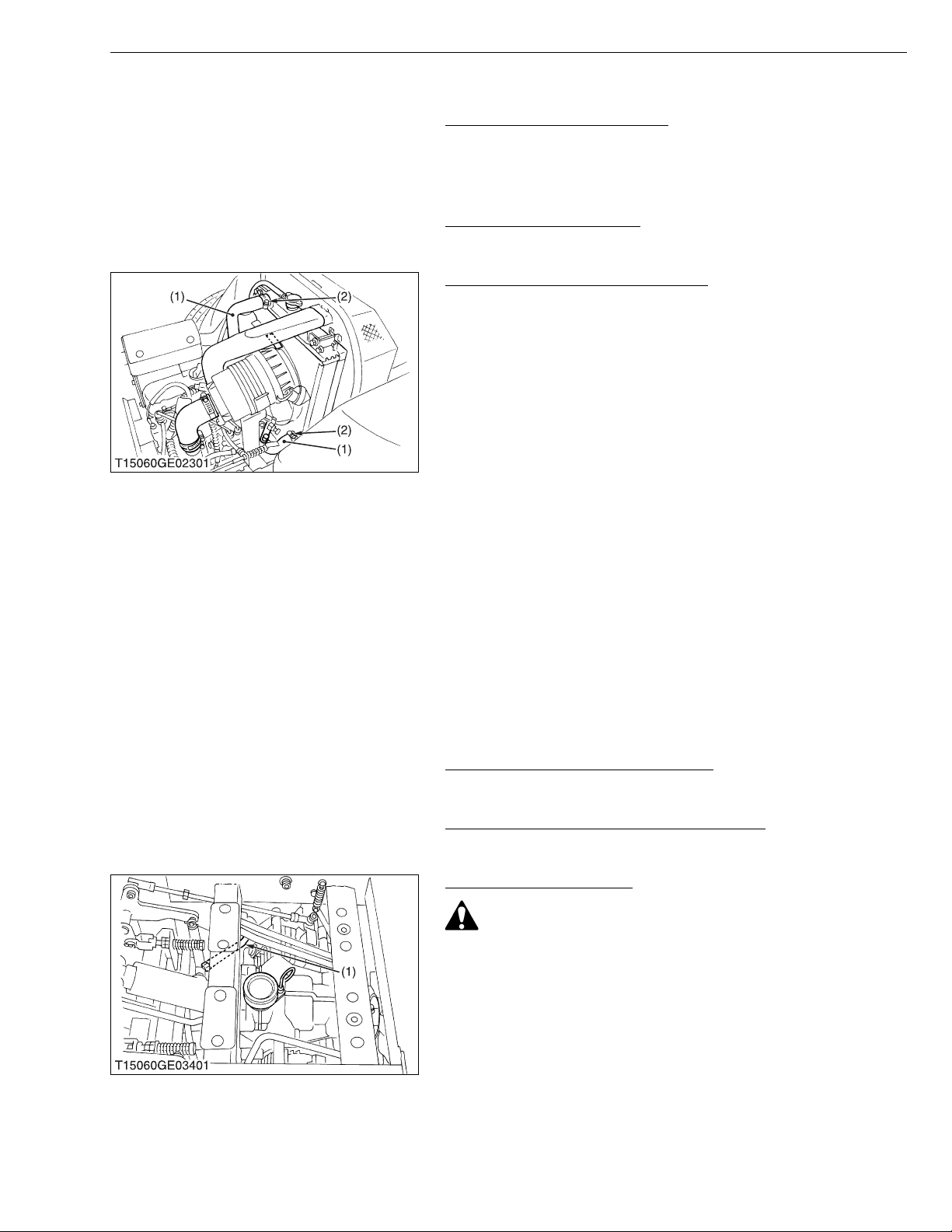
Checking Radiator Hose and Clamp
• Check to see if the radiator hos es are properly fi xed every
200 hours of operation or 6 months, whichever comes first.
1. If clamp bands ( 2) are loo se or w ater leaks , tighten clamp band
(2) securely.
2. Replace radiator hoses (1) and tighten clamp bands (2) securely,
if radiator hoses (1) are swollen, hardened or cracked.
Replace radiator hoses (1) and clamp bands (2) every 2 years or
earlier if checked and found that hoses are swollen, hardened or
cracked.
G GENERAL
W1036280
W1036862
• Take the following actions in the event the coolant
temperature be nearly or more than the boiling point, what is
called “Overheating”.
• Park the machine in a safe place and keep the engine
unloaded idling.
• Don’t stop the engine suddenly, but stop it after about 5
minutes of unloaded idling
• Keep yourself well away from the machine for further 10
minutes or while the steam is blown out.
• Checking that there gets no danger such as burning, get rid
of the causes of overheating and then start the engine again.
(1) Radiator Hose (2) Clamp Band
W1036392
Changing Engine Oil Filter Cartridge
1. See page G-18.
W1061492
Replacing Transmission Oil Filter Cartridge
1. See page G-18.
W1061793
Checking Hydraulic Hose
CAUTION
To avoid personal injury:
• Be sure to stop the engine and remove the key before
checking and replacing hydraulic hose.
• Allow transmission case to cool down sufficiently; oil can be
hot and may cause burns.
1. Check to see the hose is tight and not damaged.
2. If the worn or damaged of the hose is found, replace it..
(1) Mower Lift Cylinder Hose
W1036641
G-31
Page 45
ZD21N-EC, ZD21-EC, ZD28-EC, WSM
NOTE■
KiSC issued 09, 2006 A
G GENERAL
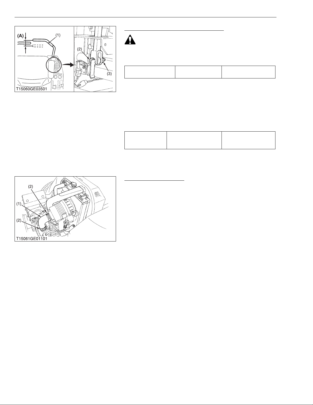
Adjusting the Motion Control Lever Pivot
CAUTION
To avoid personal injury:
• Be sure to stop the engine and set the parking brake t o “ON”
before checking.
Lever free travel (A) Factory spec.
2 to 15 mm
0.08 to 0.59 in.
1. Set the motion control lever (1) in the “NEUTRAL” position.
2. Slightly move the lever back and forth and measure the free
travel at the top of lever stroke.
3. If the free travel limits are exceeded, remove the fender and
retighten the nut (3) to specified torque.
• If the motion control lever pivot bolt (2) is maladjusted,
motion control may be difficult.
Tightening torque Pivot bolt
18.6 to 20.6 N·m
1.9 to 2.1 kgf·m
13.7 to 15.2 ft-lbs
(1) Motion Control Lever
(2) Bolt
(3) Nut
(A) Free Travel
W1063124
Checking Intake Air Line
1. Check to see that hoses and hose clamps are tight and not
damaged.
2. If hoses and clamps are found worn or damaged, replace or
repair them at once.
(1) Hose (2) Clamp
W1037686
G-32
Page 46
ZD21N-EC, ZD21-EC, ZD28-EC, WSM
■
IMPORTANT■
KiSC issued 09, 2006 A
[9] CHECK POINTS OF EVERY 400 HOURS
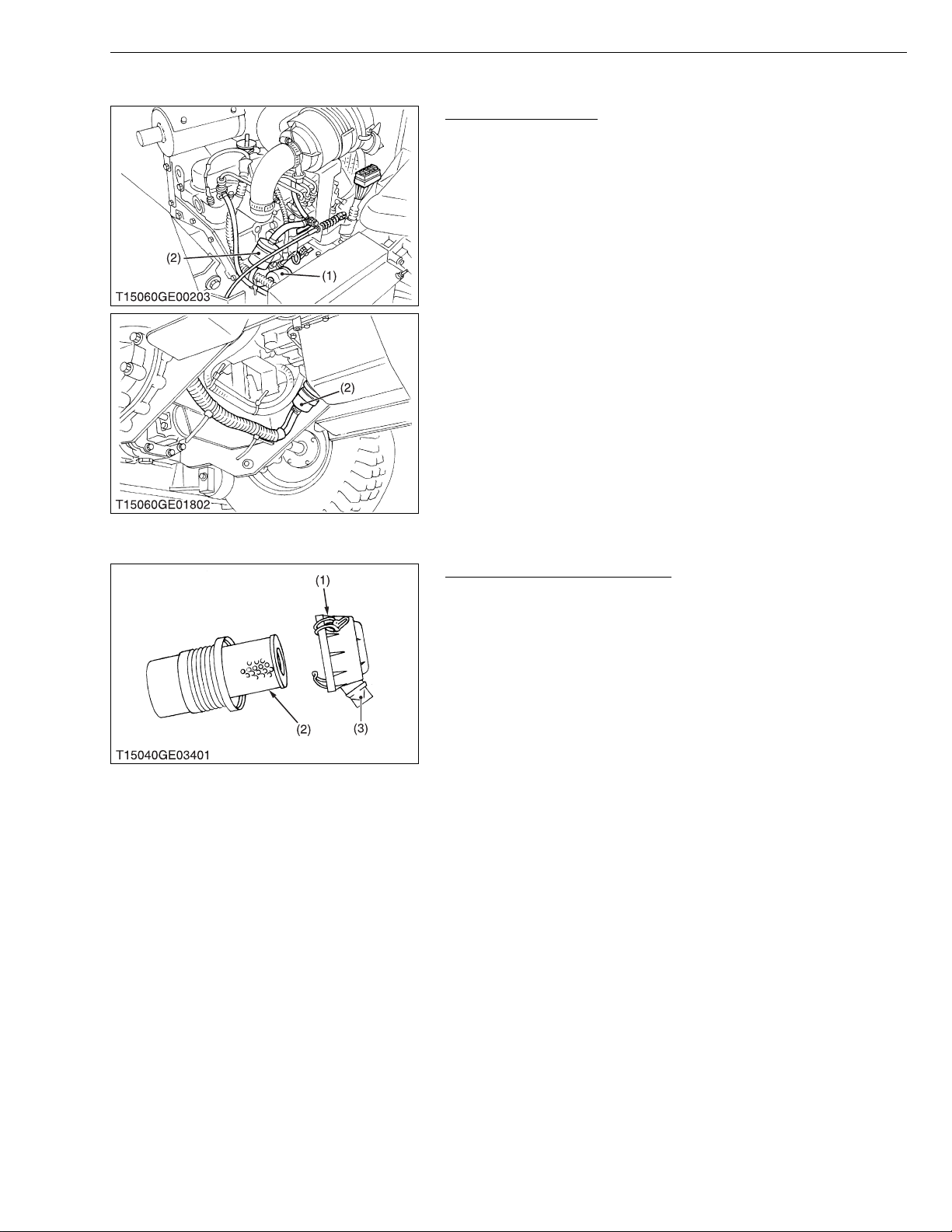
Replacing Fuel Filter
1. Disconnect the fuel hoses and loosen the f ilter band to replace
the fuel filter (2).
NOTE
• If the fuel line is removed, be sure to properly bleed the fuel
system. (See page G-38.)
(1) Fuel Pump (2) Fuel Filter
G GENERAL
W1037174
[10] CHECK POINTS OF EVERY 1 YEAR
Replacing Air Cleaner Element
1. Remove the air cleaner element (2) once a year.
• The air cleaner uses a dry element, never apply oil.
• Do not run the engine with filter element removed.
• Be sure to refit the air cleaner cover (1) as shown in the
figure. If the air cleaner cover (1) is improperly fitted,
evacuator valve (3) will not function and dust will adhere to
the element.
• If it is loose, dust and dirt may be sucked in, wearing down
the cylinder and piston rings earlier and thereby resulting in
poor power output.
(1) Air Cleaner Cover
(2) Air Cleaner Element
(3) Evacuator Valve
W1037268
G-33
Page 47
ZD21N-EC, ZD21-EC, ZD28-EC, WSM
■
KiSC issued 09, 2006 A
G GENERAL
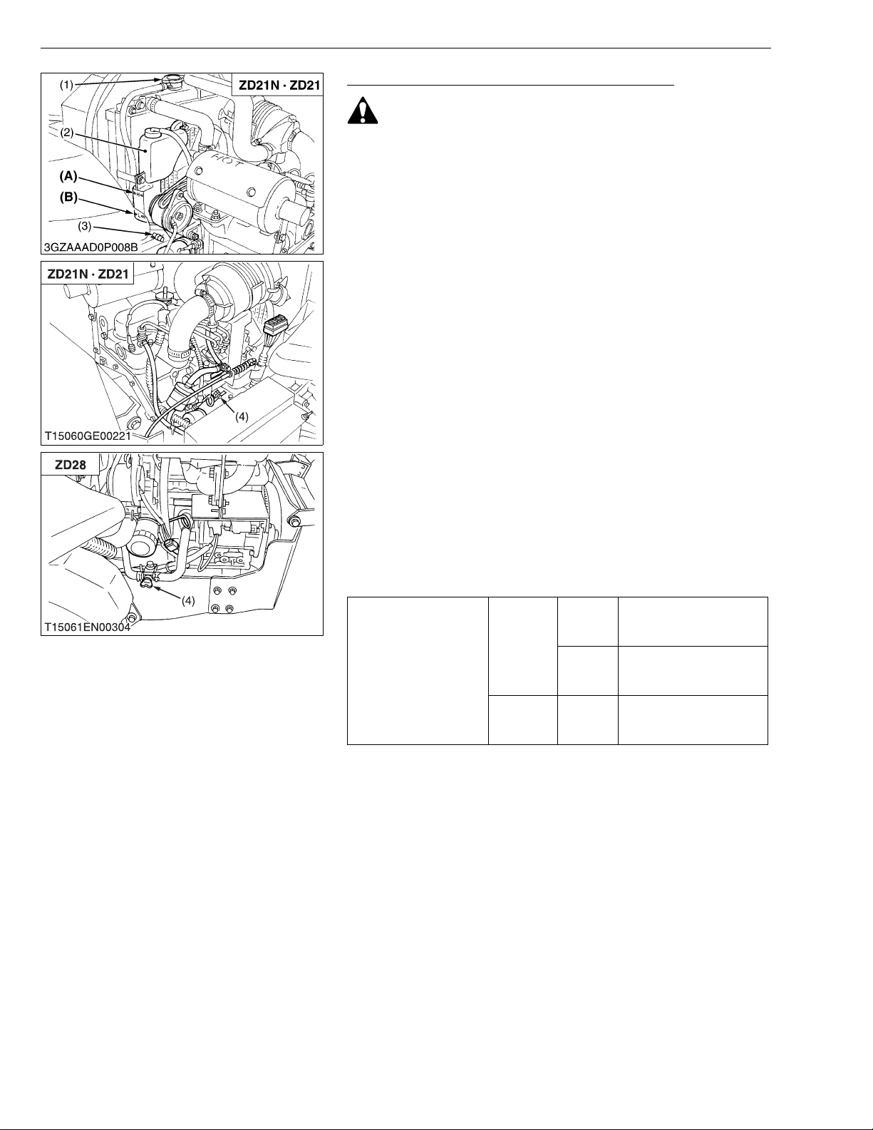
Flushing Cooling System and Changing Coolant
CAUTION
• Do not remove the radiator cap when the engine is hot. Then
loosen cap slightly to the stop to relieve any excess
pressure before removing cap completely.
1. Stop the engine and let cool down.
2. To drain the coolant, open the radiator drain plug (3) and remove
the radiator cap (1) . The radiator cap (1) must be removed to
completely drain the coolant.
3. After all coolant is drained, close the drain plug (3).
4. Fill with clean water and cooling system cleaner.
5. Follow directions of the cleaner instruction.
6. After flushing, fill with clean water and anti-freeze until the coolant
level is just below the port. Install the radiator cap (1) securely.
7. Fill with coolant up to “FULL” mark on the recovery tank.
8. Start and operate the engine for a few minutes.
9. Stop the en gine and let cool. Check cool ant level of recovery
tank (2) and add coolant if necessary.
IMPORTANT
• Do not start engine without coolant.
• Use clean, fresh water and anti-freeze to fill the radiator and
recovery tank.
• When the anti-freeze is mixed with water, the anti-freeze
mixing ratio must be less than 50 %.
• Securely tighten radiator cap. If the cap is loose or
improperly fitted, water may leak out and the engine could
overheat.
• Refer to “LUBRICANTS, FUEL AND COOLANT”. (See page
G-7.)
2.6 L
2.7 U.S.qts.
2.3 Imp.qts.
3.8 L
4.0 U.S.qts.
3.3 Imp.qts.
0.25 L
0.26 U.S.qts.
0.22 Imp.qts.
Coolant capacity
Cooling
system
Recovery
tank
ZD21N
ZD21
ZD28
ZD21N
ZD21
ZD28
(1) Radiator Cap
(2) Recovery Tank
(3) Drain Plug
(4) Drain Cock
G-34
(A) FULL
(B) LOW
W1037402
Page 48
ZD21N-EC, ZD21-EC, ZD28-EC, WSM
NOTE■
KiSC issued 09, 2006 A
G GENERAL
Flushing Cooling System and Changing Coolant (Continued)
■ Anti-Freeze
If coolant freezes, the cylinders and radiator can be damaged. It
is necessary, if the ambient temperature falls below 0 °C (32 °F),
to remove coolant mix it with anti-freeze and full the radiator with
it.
1. There are two types of anti-fr eeze availab le; use the perma nent
type (PT) for this engine.
2. Before adding anti-freeze for the first time, clean the radiator
interior by pouring fresh water and draining it a few times.
3. The procedure for mixing of water and anti-freeze differs
according to the maker of the anti-freeze and the ambient
temperature, basicall y should be referred to SAE J1034, more
specially also to SAE J814c.
4. Mix the anti-freeze with water, and then fill in to the radiator.
Vol % Antifreeze
40 – 24 – 12 106 222
50 – 37 – 34 108 226
Freezing Point Boiling Point*
°C °F °C °F
* At 101 kPa (760 mmHg) pressure (atmospheric). A higher
boiling point is obt ained by usin g a radiator pressure cap which
permits the development of pressure within the cooling system.
• The above date represent industry standards that
necessitate a minimum glycol con tent in the concentrates
anti-freeze.
• When the coolant level drops due to evaporation, add water
only. In case o f leakage, add anti-freeze and water in the
specified mixing ratio.
• Anti-freeze absorb s moist ure. Kee p un used a nti-f re ez e in a
tightly sealed container.
• Do not use radiator cleaning agents when anti-freeze has
been added to the coolant. (Anti-freeze contains an anticorrosive agent, which will react with the radiato r cleaning
agent forming sludge which will affect the engine parts.)
W1037674
G-35
Page 49
ZD21N-EC, ZD21-EC, ZD28-EC, WSM
KiSC issued 09, 2006 A
[11] CHECK POINT OF EVERY 2 YEARS
Replacing Hydraulic Hose
1. Replace the hose.
Refer to “Checking Hydraulic Hose” . (See page G-31.)
Replacing Radiator Hose
1. Replace the hoses and clamps.
Refer to “Checking Radiator Hos e and Hose Clamp”. (See
page G-31.)
Replacing Fuel Lines
1. Replace the fuel line.
Refer to “Checking Fuel Lines and Fuel Filter”. (See page G-
28.)
Replacing Intake Air Line
1. Replace the intake air line.
Refer to “Checking Intake Air Line”. (See page G-32.)
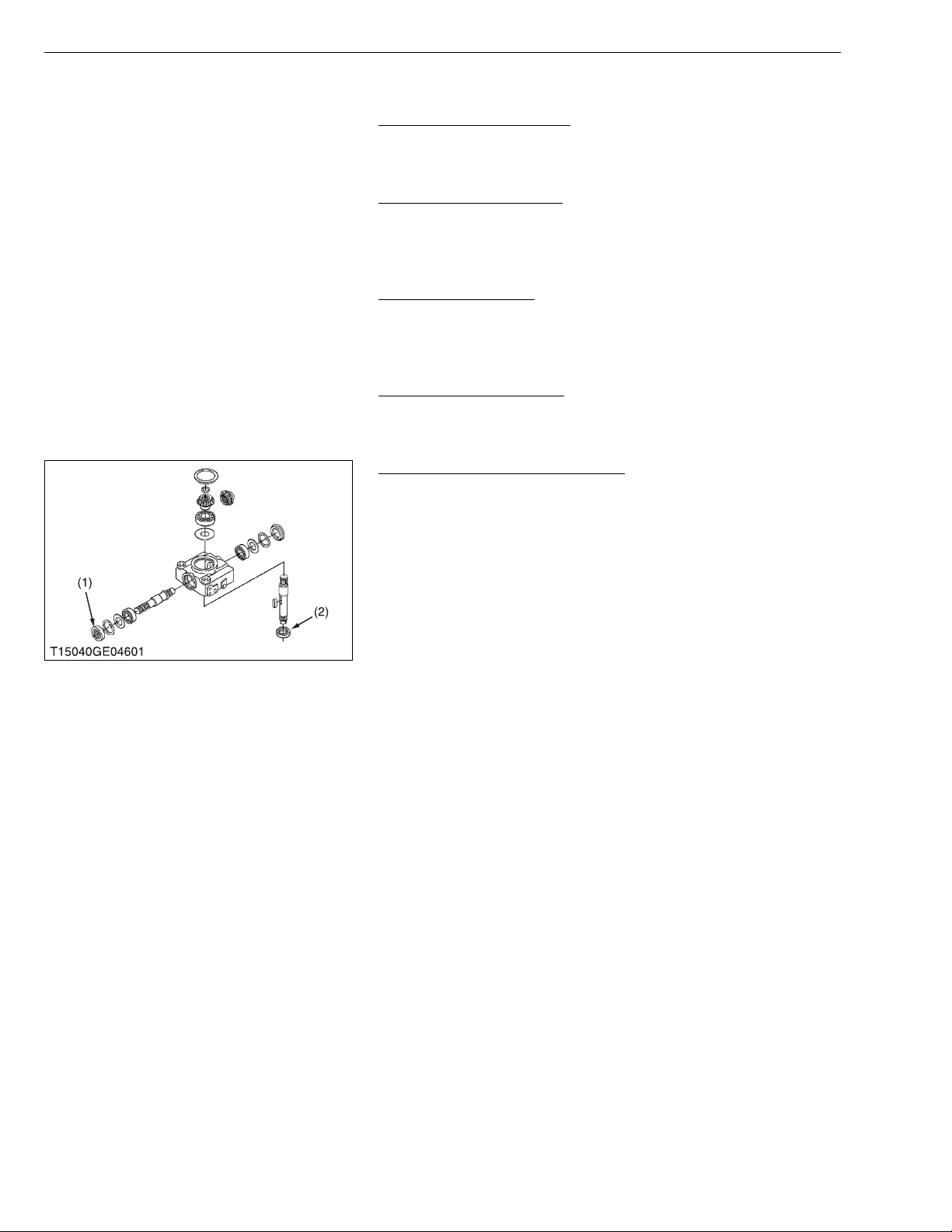
Replacing Mower Gear Box Seals
1. Replace the mower gear box oil seals (1), (2).
Refer to “Disassembling Gea r Box Asse mbly”. ( Se e pa ge 6 S8.)
(1) Oil Seal (2) Oil Seal
G GENERAL
W1067327
W1067436
W1082371
W1037080
W1038357
G-36
Page 50
ZD21N-EC, ZD21-EC, ZD28-EC, WSM
IMPORTANT■
NOTE■
KiSC issued 09, 2006 A
[12] OTHERS
G GENERAL
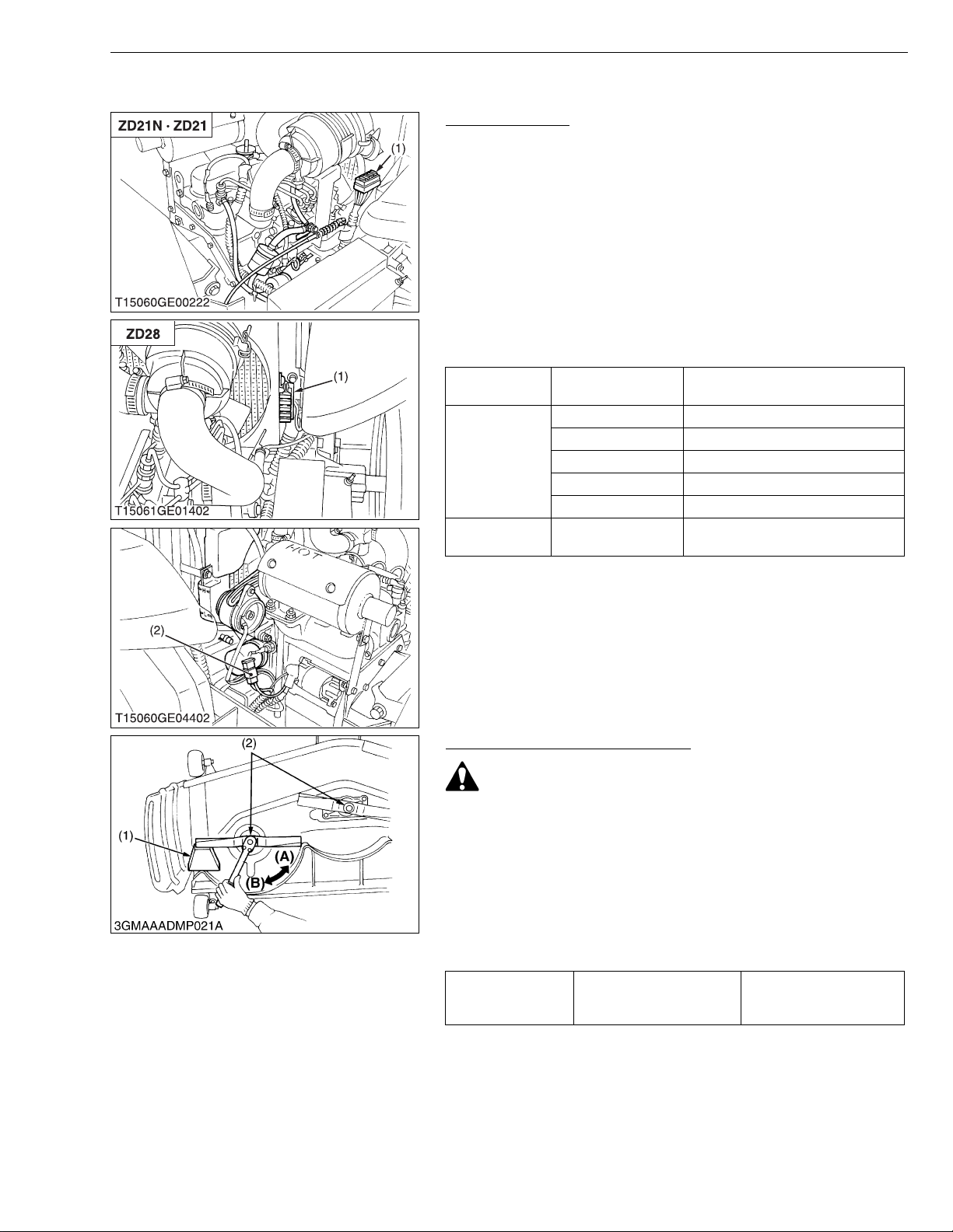
Replacing Fuses
1. The electrical system is protected from potential damage by
fuses.
A blown fuse indicates that there is an overload or short
somewhere in the electrical system.
2. If any of the fuses should blo w, replace with a new one of the
same capacity.
• Before replacing a blown fuse, determine why the fuse blew
and make any necessary repairs. Failure to follow this
procedure may result in serious damage to the electrical
system.
■ Protected Circuit
FUSE NO.
(ID LABEL)
1
2 Slow blow fuse 40 A
(1) Fuse (2) Slow Blow Fuse
CAPACITY
(A)
20A Engine stop
15A Charge system
15A Aux. outlet
15A Main system
10A Control system
Check circuit against wrong battery
connection
Protected circuit
W1038470
Retightening Mower Blade Screw
CAUTION
• To avoid injury, always handle the mower blade with care.
1. Tilt up the mower and turn it over to expose the mower blades.
2. Wedge a woode n block (1) sec urely between the mower blade
and mower deck.
3. Retighten the mower blade screw to the specified torque.
4. If the mower blade screw (2) is worn or broken, replace it.
• The screw of the red-painted mower blade is of inverse
helical type.
Tightening torque Mower blade screw
(1) Wooden Block
(2) Mower Blade Screw
(A) Loosen
(B) Tighten
98.0 to 117.6 N·m
10.0 to 12.0 kgf·m
72.0 to 86.8 ft-lbs
W1022525
G-37
Page 51
ZD21N-EC, ZD21-EC, ZD28-EC, WSM
NOTE■
NOTE■
KiSC issued 09, 2006 A
G GENERAL
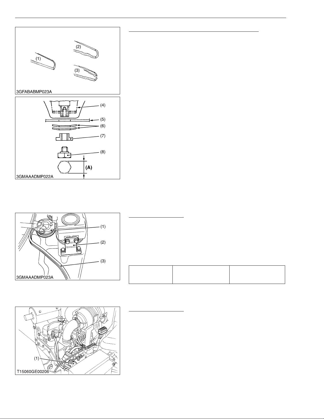
Checking Mower Blade and Replacing Mower Blade
1. Check the cutting edge of mower blade.
2. Sharpen the cu tting edge s, if the mower blades ar e as shown in
figure (2).
3. Replace the mower blades, if they are as shown in figure (3).
• To sharpen the mower blades by yourself, clamp the mower
blade securely in a vise a nd use a large mill file along the
original bevel.
• To balance the mower blade, place a small rod through the
center hole and check to see if the blade balances evenly.
File heavy side of the blade until it balance out even.
4. Tilt up the mower deck.
5. Wedge a wooden block s ecurel y bet ween th e mowe r blad e and
mower deck or use a box wrench ove r the pulley nut to prevent
the spindle from rotating while removing the blade bolts; then
loosen the blade bolts.
6. Pass the sp line boss through th e blade (5) and 2 cup wa shers
(6), and tighten the bolt (8).
• Make sure that the cup w asher is not flatten ed out or wor n;
this cause blade to slip excessively.
Replace the 2 cup washers if either is damaged.
(1) New Blade
(2) Worn Blade
(3) Cracked Blade
(4) Spindle Holder
(5) Blade
(6) 2 Cup Washers
(7) Lock Washer
(8) Bolt
(A) 30 mm (1-3/16 in.)
W1022841
Replacing Mower Belt
1. Remove the mower deck from the machine.
2. Remove the left and right hand shield from the mower deck.
3. Clean around the gear box.
4. Remove the belt from the tension pulley.
5. Remove the right hand bracket which mounts the gear box to the
mower deck and slip the belt over the top of the gear box.
6. To install a new belt, reverse the above procedure.
27.6 to 90.2 N·m
Tightening torque Bracket mounting screw
8.0 to 9.2 kgf·m
57.1 to 66.5 ft-lbs
(1) Tension Pulley
(2) Bracket (RH)
(3) Belt
W1069194
Bleeding Fuel System
Air must be removed:
1. When the fuel filter or lines are removed.
2. When tank is completely empty.
3. After the tractor has not been used for a long period of time.
Bleeding procedure is as follows:
1. Fill the fuel tank with fuel.
2. Turn the key switch to “ON” position for about 30 seconds.
Doing so allows fuel pump to work and pump air out of the fu el
system.
3. Start the engine and run for about 30 seconds, and then stop the
engine.
(1) Fuel Pump
W1069400
G-38
Page 52
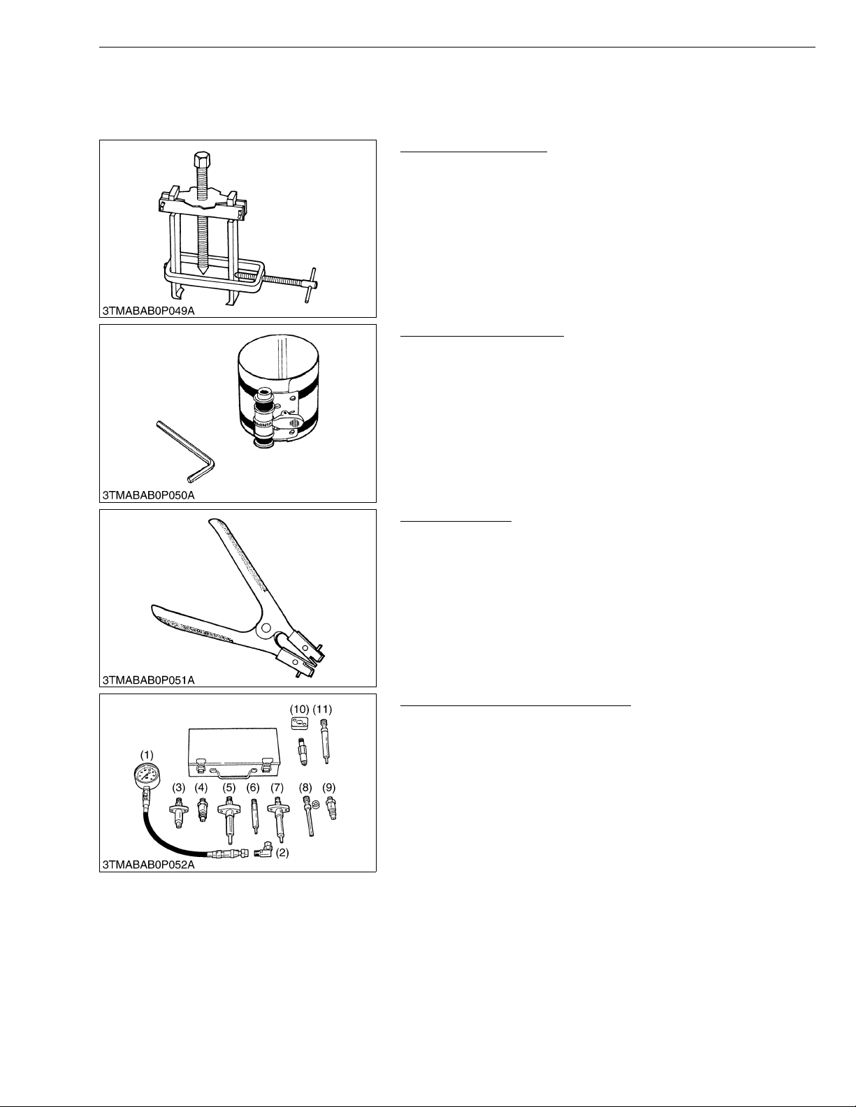
ZD21N-EC, ZD21-EC, ZD28-EC, WSM
KiSC issued 09, 2006 A
8. SPECIAL TOOLS
[1] SPECIAL TOOLS FOR ENG INE
Special Use Puller Set
Code No: 07916-09032
Application: Use exclusively for pushing out bearing, gears and
Piston Ring Compressor
Code No: 07909-32111
Application: Use exclusively for pushing in the piston with piston
G GENERAL
other parts with ease.
W1048293
rings into the cylinder.
W1048361
Piston Ring Tool
Code No: 07909-32121
Application: Use exclusively for removing or installing the piston ring
with ease.
W1048421
Diesel Engine Compression Tester
Code No: 07909-30208 (Assembly) 07909-31251 (G)
07909-30934 (A to F) 07909-31271 (I)
07909-31211 (E and F) 07909-31281 (J)
07909-31231 (H)
Application: Use to measure diesel engine compression and
diagnostics of need for major overhaul.
(1) Gauge
(2) L Joint
(3) Adaptor A
(4) Adaptor B
(5) Adaptor C
(6) Adaptor E
(7) Adap tor F
(8) Adap tor G
(9) Adap tor H
(10) Adaptor I
(11) Adaptor J
W1048481
G-39
Page 53
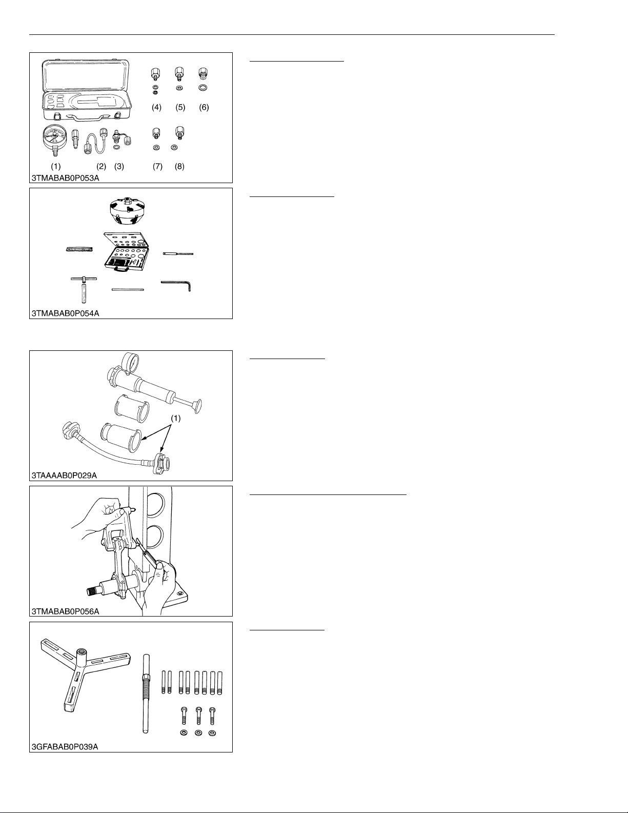
ZD21N-EC, ZD21-EC, ZD28-EC, WSM
KiSC issued 09, 2006 A
G GENERAL
Oil Pressure Tester
Code No: 07916-32032
Application: Use to measure lubricating oil pressure.
(1) Gauge
(2) Cable
(3) Threaded Joint
(4) Adaptor 1
(5) Adaptor 2
(6) Adaptor 3
(7) Adaptor 4
(8) Adaptor 5
W1048722
Valve Seat Cutter
Code No: 07909-33102
Application: Use to reseat valves.
Angle: 0.785 rad (45 °)
0.262 rad (15 °)
Diameter: 28.6 mm (1.126 in.)
31.6 mm (1.244 in.)
35.0 mm (1.378 in.)
38.0 mm (1.496 in.)
41.3 mm (1.626 in.)
50.8 mm (2.000 in.)
W1048944
Radiator Tester
Code No: 07909-31551
Application: Use to check of radiator cap press ure, and l eaks from
cooling system.
Remarks: Adapter (1) BANZAI Code No. RCT-2A-30S
W1049045
Connecting Rod Alignment Tool
Code No: 07909-31661
Application: Use to check the connecting rod alignment.
Applicable: Connecting rod big end I.D.
range 30 to 75 mm (1.18 to 2.95 in.) dia.
Connecting rod length
65 to 300 mm (2.57 to 11.81 in.)
W1049118
Flywheel Puller
Code No: 07916-32011
Application: Use exclusively for removing the flywheel with ease.
W1049723
G-40
Page 54
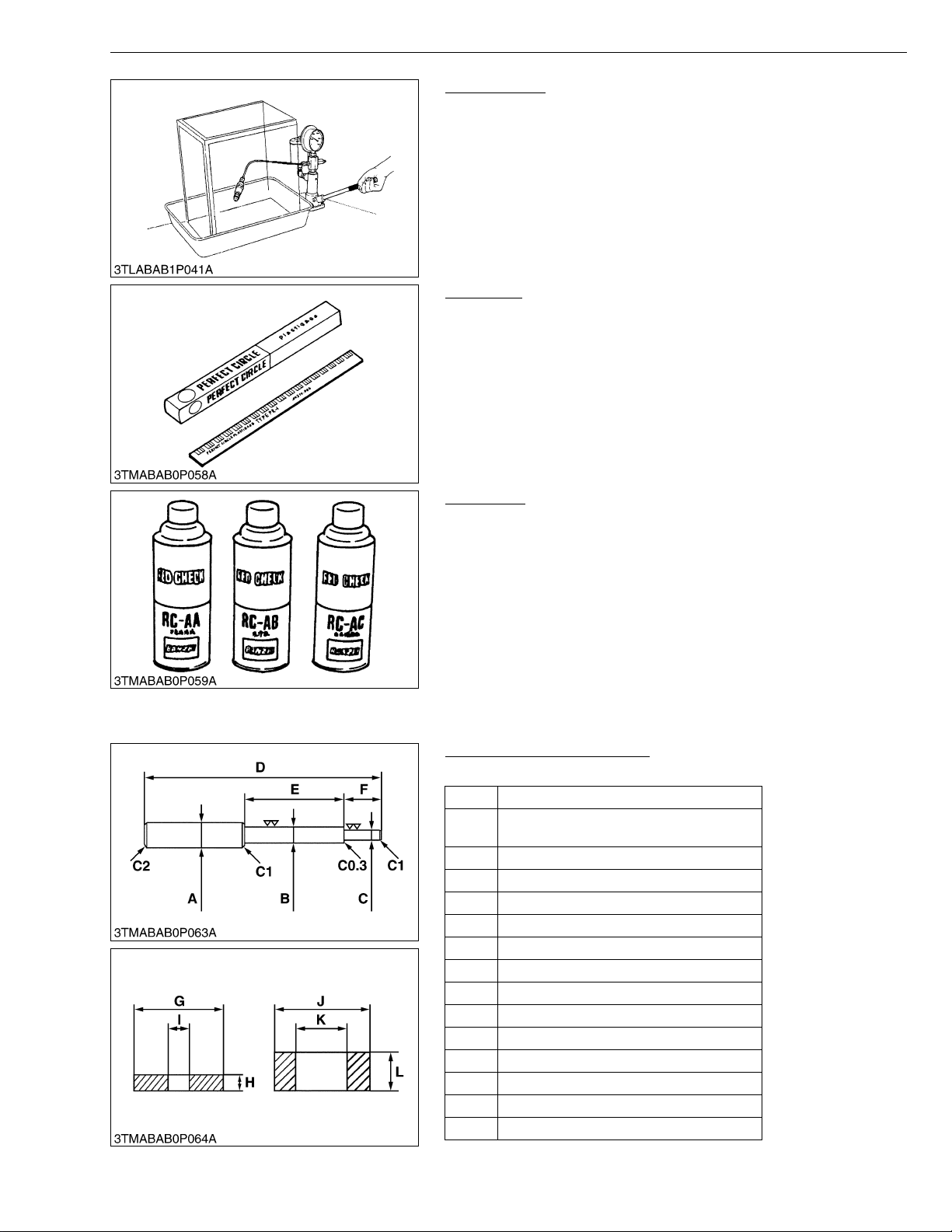
ZD21N-EC, ZD21-EC, ZD28-EC, WSM
NOTE■
KiSC issued 09, 2006 A
G GENERAL
Nozzle Tester
Code No: 07909-31361
Application: Use to check the fuel injection pressure and spray
pattern of nozzle.
Measuring: 0 to 50 MPa
2
range (0 to 500 kgf/cm
, 0 to 7000 psi)
W1049783
Plastigage
Code No: 07909-30241
Application: Use to check the oil clearance between crankshaft and
bearing, etc..
Measuring: Green.....0.025 to 0.076 mm (0.001 to 0.003 in.)
range Red........0.051 to 0.152 mm (0.002 to 0.006 in.)
Blue.......0.102 to 0.229 mm (0.004 to 0.009 in.)
W1049942
Red Check
Code No: 07909-31371
Application: Use to check cracks on cylinder head , cylinder block,
etc..
• The following special tools are not provided, so make them referring to the figure.
Valve Guide Replacing Tool
Application: Use to press out and press fit the valve guide.
A 20 mm dia. (0.79 in. dia.)
9.96 to 9.98 mm dia.
B
(0.3921 to 0.3929 in. dia.)
C 5.5 to 5.7 mm dia. (0.2165 to 0.2244 in. dia.)
D 200 mm (7.87 in.)
E 80 mm (3.15 in.)
F 40 mm (1.58 in.)
G 15 mm (0.59 in.)
H 5 mm (0.197 in.)
I 6.0 to 6.1 mm dia. (0.236 to 0.240 in. dia.)
J 18 mm dia. (0.71 in. dia.)
K 10.6 to 10.7 mm dia. (0.417 to 0.421 in. dia.)
L 7 mm (0.276 in.)
C1 Chamfer 1.0 mm (0.039 in.)
C2 Chamfer 2.0 mm (0.079 in.)
C0.3 Chamfer 0.3 mm (0.012 in.)
W1050024
W1050106
G-41
Page 55
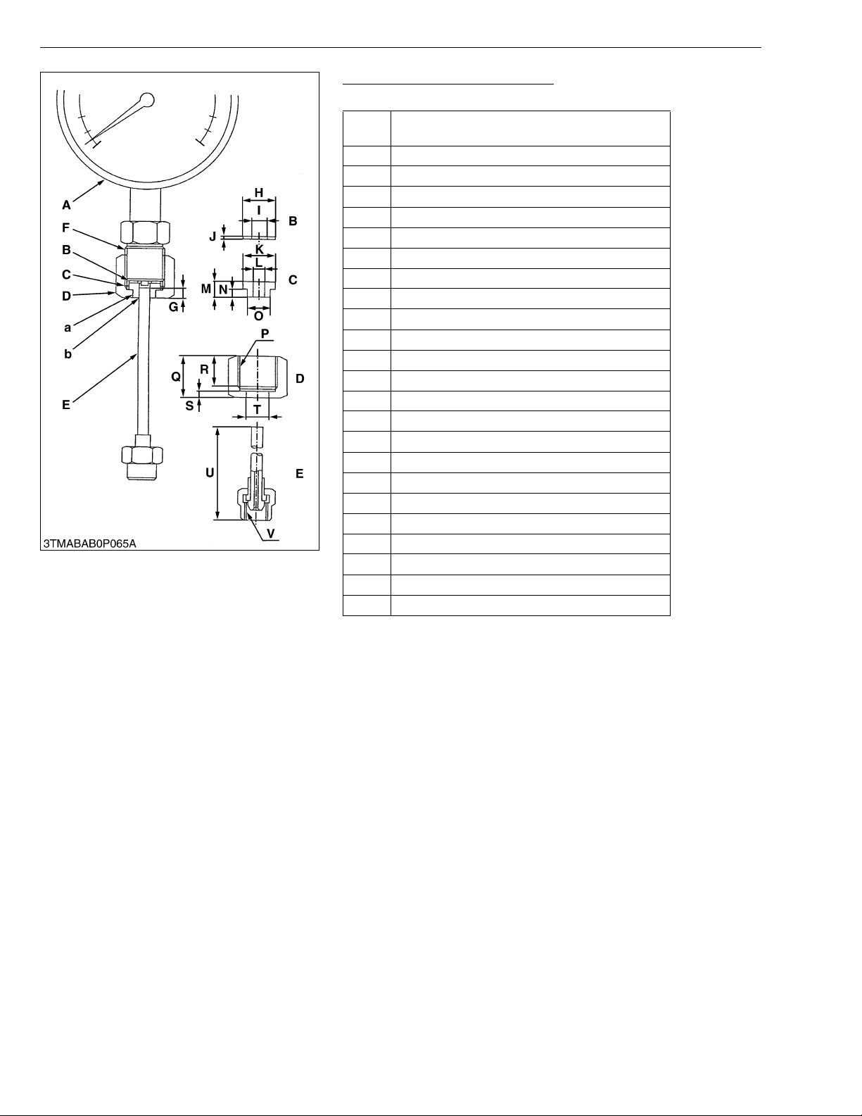
ZD21N-EC, ZD21-EC, ZD28-EC, WSM
KiSC issued 09, 2006 A
G GENERAL
Injection Pump Pressure Tester
Application: Use to check fuel tightness of injection pumps.
Pressure gauge full scale: More than
A
29.4 MPa (300 kgf/cm
B Copper gasket
C Flange (Material: Steel)
D Hex. nut 27 mm (1.06 in.) across the plat
E Injection pipe
FPF1/2
G 5 mm (0.20 in.)
H 17 mm dia. (0.67 in. dia.)
I 8 mm dia. (0.31 in. dia.)
J 1.0 mm (0.039 in.)
K 17 mm dia. (0.67 in. dia.)
L 6.10 to 6.20 mm dia. (0.2402 to 0.2441 in. dia.)
M 8 mm (0.31 in.)
N 4 mm (0.16 in.)
O 11.97 to 11.99 mm dia. (0.4713 to 0.4721 in. dia.)
PPF1/2
Q 23 mm (0.91 in.)
R 17 mm (0.67 in.)
S 4 mm (0.16 in.)
T 12.00 to 12.02 mm dia. (0.4724 to 0.4732 in. dia.)
U 100 mm (3.94 in.)
V M12 × P1.5
a Adhesive application
b Fillet welding on the enter circumference
2
, 4267 psi)
W1050289
G-42
Page 56
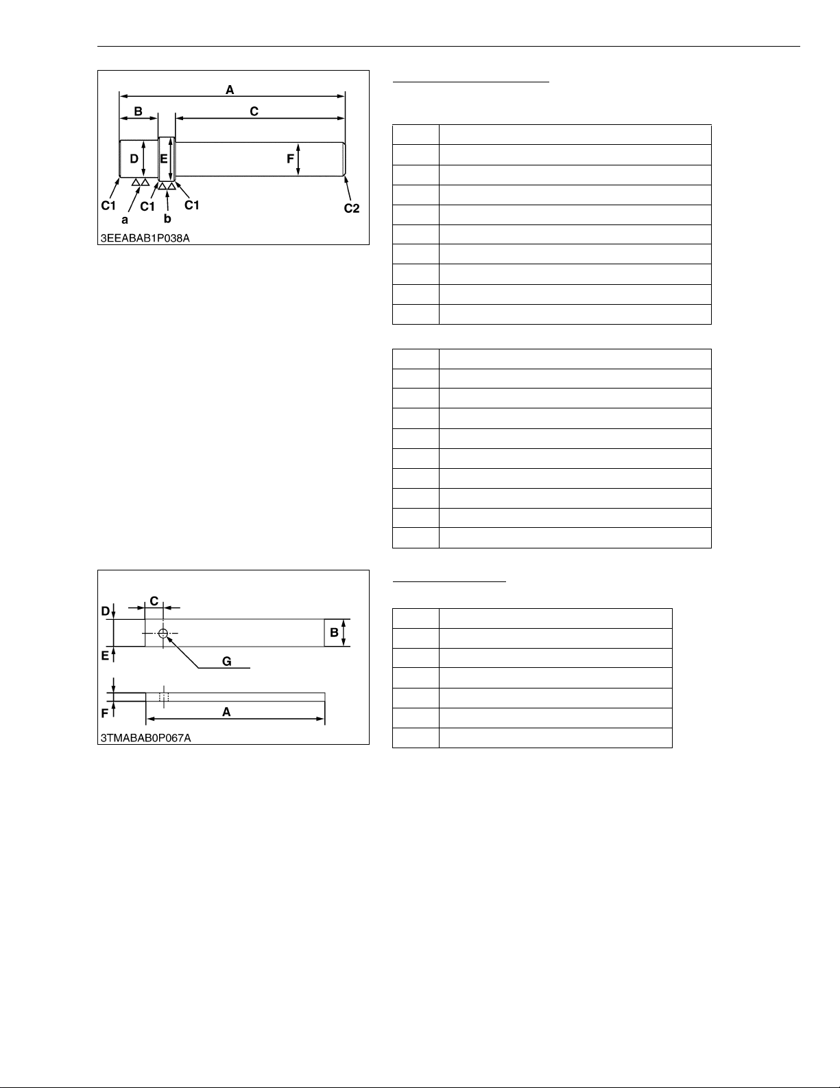
ZD21N-EC, ZD21-EC, ZD28-EC, WSM
KiSC issued 09, 2006 A
G GENERAL
Bushing Replacing Tool
Application: Use to press out and to press fit the bushing.
1. For small end bushing
A 145 mm (5.71 in.)
B 20 mm (0.79 in.)
C 100 mm (3.94 in.)
D 19.90 to 19.95 mm dia. (0.7835 to 0.7854 in. dia.)
E 21.90 to 21.95 mm dia. (0.8622 to 0.8642 in. dia.)
F 25 mm dia. (0.98 in. dia.)
a6.3 μ m (250 μ in.)
b6.3 μ m (250 μ in.)
C1 Chamfer 1.0 mm (0.039 in.)
C2 Chamfer 2.0 mm (0.079 in.)
2. For idle gear bushing
A 150 mm (5.91 in.)
B 20 mm (0.79 in.)
C 100 mm (3.94 in.)
D 19.90 to 19.95 mm (0.7835 to 0.7854 in.)
E 21.90 to 21.95 mm (0.8622 to 0.8642 in.)
F 25 mm (0.98 in.)
a6.3 μ m (250 μ in.)
b6.3 μ m (250 μ in.)
C1 Chamfer 1.0 mm (0.039 in.)
C2 Chamfer 2.0 mm (0.079 in.)
W1050660
Flywheel Stopper
Application: Use to loosen and tighten the flywheel screw.
A 200 mm (7.87 in.)
B 30 mm (1.18 in.)
C 20 mm (0.79 in.)
D 15 mm (0.59 in.)
E 15 mm (0.59 in.)
G 8 mm (0.31 in.)
F 10 mm dia. (0.39 in. dia.)
W1050819
G-43
Page 57
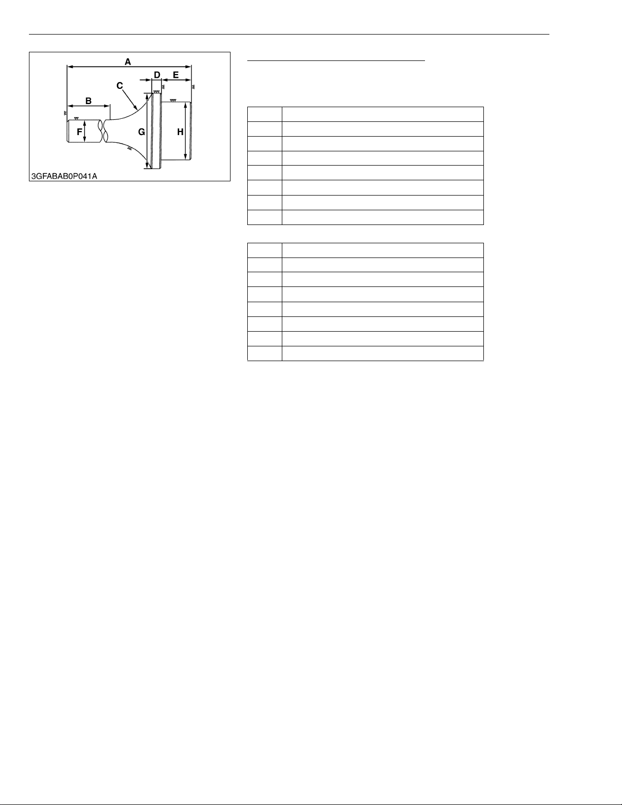
ZD21N-EC, ZD21-EC, ZD28-EC, WSM
KiSC issued 09, 2006 A
G GENERAL
Crankshaft Bearing 1 Replacing Tool
Application: Use to press out and to press fit the crankshaft bearing
1.
[Press Out]
A 135 mm (5.31 in.)
B 72 mm (2.83 in.)
C 1.57 rad (40°)
D 10 mm (0.39 in.)
E 22 mm (0.87 in.)
F 20 mm dia. (0.79 in. dia.)
G 48.90 to 48.95 mm dia. (1.9251 to 1.9271 in. dia.)
H 43.90 to 43.95 mm dia. (1.7283 to 1.7303 in. dia.)
[Press Fit]
A 130 mm (5.12 in.)
B 72 mm (2.83 in.)
C 1.57 rad (40°)
D 9 mm (0.35 in.)
E 24 mm (0.95 in.)
F 20 mm dia. (0.79 in. dia.)
G 68 mm dia. (0.79 in. dia.)
H 39.90 to 39.95 mm dia. (1.5709 to 1.5728 in. dia.)
W1051113
G-44
Page 58
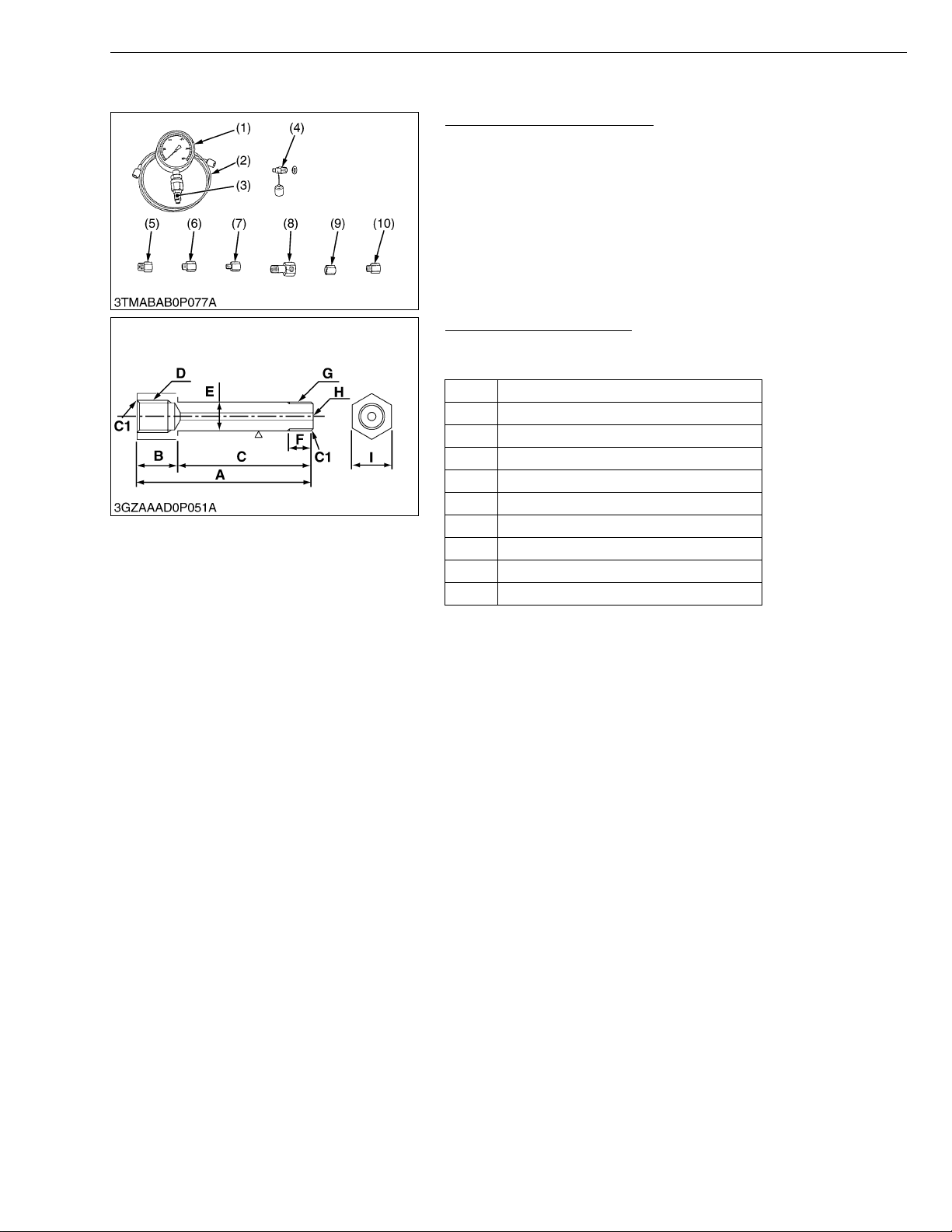
ZD21N-EC, ZD21-EC, ZD28-EC, WSM
KiSC issued 09, 2006 A
[2] SPECIAL TOOLS FOR MA CHIN E
Relief Valve Pressure Tester
Code No: 07916-50045
Application: This allows easy measurement of relief set pressure.
(1) Gauge (07916-50322)
(2) Cable (07916-50331)
(3) Threaded Joint (07916-50401)
(4) Threaded Joint (07916-50341)
(5) Adaptor B (M18 × P1.5)
(07916-50361)
HST Relief Valve Adaptor
Application: This adaptor is used to measure the HST relief valve
A 80 mm (3.15 in.)
B 20 mm (0.79 in.)
C 60 mm (2.36 in.)
D G 1/4 × 15 mm (0.59 in.)
E 12 mm (0.47 in.)
F 13 mm dia. (0.51 in. dia.)
GG 1/4
H 3 mm dia. (0.118 in. dia.)
I 19 mm (0.75 in.)
C1 Chamfer 1.0 mm (0.039 in.)
G GENERAL
(6) Adap tor C (PS3/8) (07916-50371)
(7) Adap tor D (PT1/8) (07916-50381)
(8) Adap tor E (PS 3 /8) (07916-50392)
(9) Adap tor F (PF1/2) (07916-62601)
(10) Adaptor 58 (PT1/4) (07916-52391)
W1051907
pressure.
W1040355
G-45
Page 59

1 ENGINE
KiSC issued 09, 2006 A
Page 60

MECHANISM
KiSC issued 09, 2006 A
CONTENTS
1. FUEL SYSTEM ............................................................................................. 1-M1
[1] GOVERNOR ............................................................................................1-M1
Page 61
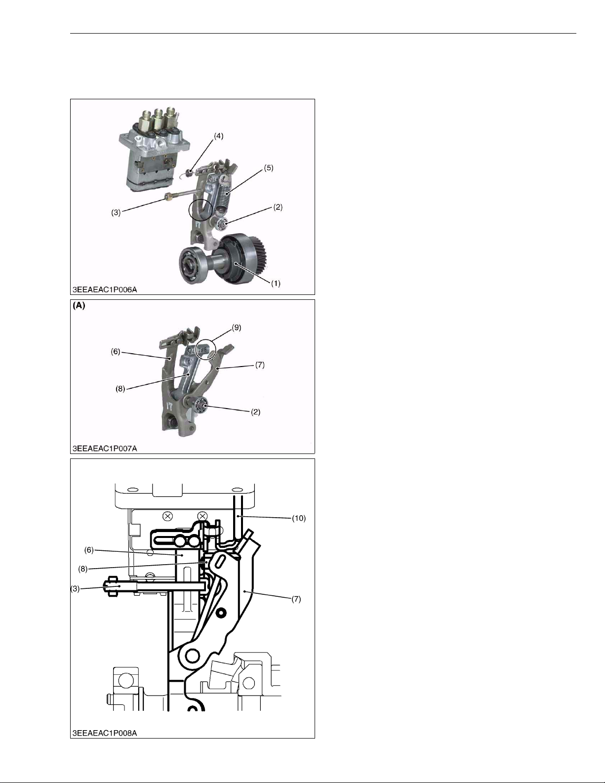
ZD21N-EC, ZD21-EC, ZD28-EC, WSM
KiSC issued 09, 2006 A
1. FUEL SYSTEM
[1] GOVERNOR
ENGINE
The governor s ystem is a mechanic al governor that
used the flyweight (1).
The flyweight (1) is mounted on the governor shaft
that rotates at the same speed as the crankshaft.
Because the feature o f thi s mec han is m ta ke s ou t the
engine rotational speed dir ectly as a centrif ugal forc e of
weight, the speed control that the change in the eng ine
rotational speed is sensitively transmitted to fork lever
comp (A) and accuracy is high is enabled.
The fork lever assembly of this engine is composed of
fork lever 1 (6), fork leve r 2 (7), and t he floati ng lever (8).
A thrust lever is i nstalled in fork lever 1. The gove rnor
spring (5) is hooked to fork lever 2 (7).
The floating leve r (8) ins talls the torque pin (9) of the
output drop prevention at the overload . The star t spring
(4) is hooked to a thrust lever, and holds the control rack
in the direction of the increase.
Fork lever 2 (7) and the floa ting lever ar e install ed in
fork lever 1 (6) with the fork lever shaft (2). The max.
torque limitatio n (3) device lim its the amount of the fuel
exhalation at the overload with the torque pin.
(1) Flyweight
(2) Fork Lever Shaft
(3) Max. Torque Limitation
(4) Start Spring
(5) Governor Spring
(6) Fork Lever 1
(7) Fork Lever 2
(8) Floating Lever
(9) Torque Pin
(A) Fork Lev e r Co m p
0000004865E
■ At Rated Operation
When the engine is ru nning, the fork lever 2 (7) and
the floating leve r (8) ar e mov ing with t he for k lever 1 (6)
due to the tension of the governor spring (5).
During the time, the torque pin (9) is pressed into the
floating lever by cen trifu gal forc e of the go vernor weigh t
(1).
The fork lever 2 (7) comes in contact with the fuel
limitation bolt (10), and th e fuel injection pump s upplies
necessary fuel for rated operation.
(3) Max Torque Limiter
(6) Fork Lever 1
(7) Fork Lever 2
(8) Floating Lever
(10) Fuel Limitation Bolt
0000004866E
1-M1
Page 62
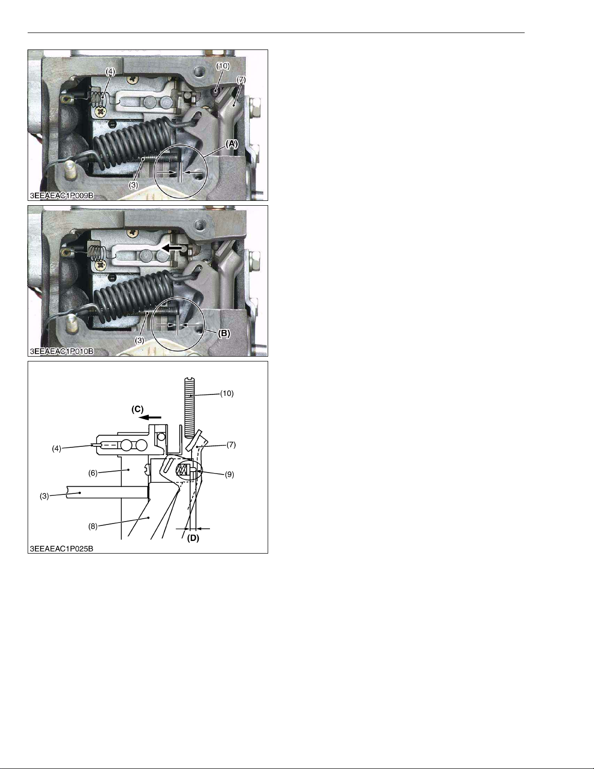
ZD21N-EC, ZD21-EC, ZD28-EC, WSM
KiSC issued 09, 2006 A
ENGINE
■ Overloaded Operation
The amount of the mo ve men t of the fork lever co mp.
is limited with the fuel limi tation b olt (10 ) and can no t be
moved in the direction of the fuel increase.
As overload reduces the centrifugal force of the
governor weight, which is pressing the torque pin (9) into
the floating lever (8), the torque pin pushes the fork lever
1 (6) in the way to in cr ea se the fuel supply with the he lp
of the torque spring tension.
The fuel supply increases (C) in relation to the degree
of the torque pin motion, thus preventing the engine
speed from dropping.
At the time, the maximum to rque limiter (3) pr events
superfluous fuel supp ly and suppresses the gener ation
of black smoke.
(3) Max. Torque Limiter
(4) Start Spring
(6) Fork Lever 1
(7) Fork Lever 2
(8) Floating Lever
(9) Torque Pin
(10) Fuel Limitation Bolt
(A) Distance Where Rack
Moves (Amount of a fuel
increase at overload)
(B) The Max. Torque Limiter
Worked
(C) Increase of Fuel
(D) Distance t o Which Torque
Pin (9) Pushes Fork Lever 1
(6) Out
W1013813
1-M2
Page 63

SERVICING
KiSC issued 09, 2006 A
CONTENTS
1. TROUBLESHOOTING....................................................................................1-S1
2. SERVICING SPECIFICATIONS[D782-E-XFM5] ...........................................1-S5
[1] ENGINE BODY ........................................................................................1-S5
[2] LUBRICATING SYSTEM ............................... ...... ....... ...... ....... ...... ....... ...1-S9
[3] COOLING SYSTEM.................................................................................1-S9
[4] FUEL SYSTEM ....................................... ....... ...... ....... ...........................1-S10
3. SERVICING SPECIFICATIONS[D1105-E2-ZD] ..........................................1-S11
[1] ENGINE BODY ......................................................................................1-S11
[2] LUBRICATING SYSTEM ............................... ...... ....... ...... ....... ...... ....... .1-S15
[3] COOLING SYSTEM...............................................................................1-S15
[4] FUEL SYSTEM ....................................... ....... ...... ....... ...........................1-S16
4. TIGHTENING TORQUES ............................. ....... ...... ....... ...... ....... ...... ....... .1-S17
5. CHECKING, DISASSEMBLING AND SERVICING.....................................1-S19
[1] SEPARATING ENGINE .......................... ....... ...... ....... ...... ....... ...... ....... .1-S19
(1) Disassembling and Assembling ........................................................1-S19
[2] ENGINE BODY ......................................................................................1-S25
(1) Checking and Adjus ti ng ..................... ....................................... ....... .1-S25
(2) Disassembling and Assembling ........................................................1-S28
(3) Servicing ...........................................................................................1-S42
[3] LUBRICATING SYSTEM ............................... ...... ....... ...... ....... ...... ....... .1-S66
(1) Checking ...........................................................................................1-S66
(2) Servicing ...........................................................................................1-S66
[4] COOLING SYSTEM...............................................................................1-S68
(1) Checking and Adjus ti ng ..................... ....................................... ....... .1-S68
(2) Disassembling and Assembling ........................................................1-S70
[5] FUEL SYSTEM ....................................... ....... ...... ....... ...........................1-S71
(1) Checking and Adjus ti ng ..................... ....................................... ....... .1-S71
(2) Disassembling and Assembling ........................................................1-S74
Page 64

ZD21N-EC, ZD21-EC, ZD28-EC, WSM
KiSC issued 09, 2006 A
1. TROUBLESHOOTING
ENGINE
Symptom Probable Cause Solution
Engine Does Not
Start
(Starter Does Not
Run)
• No fuel
• Air in the fuel system
• Water in the fuel system
• Fuel pipe clogged
• Fuel filter clogged
• Excessively high viscosity of fuel or engine oil
at low temperature
• Fuel with low cetane number
• Fuel leak due to l oos e inj ect ion pip e ret a ini ng
nut
• Incorrect injec tio n timi ng
• Fuel camshaft worn
• Injection nozzle clogged
• Injection pump malfunctioning
• Seizure of crankshaft, camshaft, piston,
cylinder or bearing
• Compression leak from cylinder
• Improper valve timing
• Piston ring and cylinder worn
• Excessive valve clearance
• Battery discharged
• Starter malfunctioning
• Slow blow fuse blown
• Main switch malfunctioning
• PTO switch defective
• Parking brake switch defective
• Motion control lever switch defective
• Seat switch defective
• Wiring harness disconnected
Replenish fuel
Bleed fuel system
Change fuel and
replace fuel system
Clean fuel pipe
Replace fuel filter
Use specified fuel or
engine oil
Use specified fuel
Tigh ten retaining nut
Adjust injection
timing
Replace fuel
camshaft
Clean injection
nozzle
Repair or replace
injection pump
Replace crankshaft,
camshaft, piston,
cylinder or bearing
Replace head
gasket, tighten
cylinder head screw,
glow plug and nozzle
holder
Correct valve timing
Replace pi ston ring
and bore oversize
cylinder
Adjust valve
clearance
Charge battery
Repair or replace
starter
Replace slow blow
fuse
Repair or replace
main switch
Replace PTO switch
Replace brake switch
Replace reverse
switch or adjust
reverse switch gap
Replace seat switch
Connect wiring
harness
Reference
Page
–
–
–
–
G-33
G-7
G-7
1-S28
1-S71
1-S33, S35
1-S74
1-S31, S35
1-S39, S40
1-S30
1-S32, S36
1-S39, S65
1-S27
G-27
5-S12
G-37
5-S8
5-S10
5-S10
5-S10
5-S10
–
W1066187
1-S1
Page 65

ZD21N-EC, ZD21-EC, ZD28-EC, WSM
KiSC issued 09, 2006 A
ENGINE
Symptom Probable Cause Solution
Engine Revolution Is
Not Smooth
• Fuel filter clogged or dirty
• Air cleaner clogged
Replace fuel filter
Clean or replace air
cleaner element.
• Fuel leak due to loose injection pipe retaining
Tighten retaining nut
nut
• Injection pump malfunctioning
Repair or replace
injection pump
• Incorrect nozzle injection pressure
Adjust nozzle
injection pressure
• Injection nozzle stuck or clogged
Repair or replace
injection nozzle
Either White or Blue
Exhaust Gas Is
Observed
• Governor malfunctioning
• Excessive engine oil
• Piston ring and cylinder worn or stock
Repair governor
Reduce to specified
engine oil level
Repair piston ring
and bore oversize
piston
• Incorrect injection timing
Adjust injection
timing
• Deficient compression
Replace each
bearings
Either Black or Dark
Gray Exhaust Gas Is
Observed
•Overload
• Low grade fuel used
• Fuel filter clogged
• Air cleaner clogged
Lessen load
Use specified fuel
Replace fuel filter
Clean or replace air
cleaner element
• Deficient nozzle injection
Repair or replace
nozzle
Deficient Output • Incorrect injection timing
Adjust injection
timing
• Engine's moving parts seem to be seized.
Repair or replace
engine’s moving
parts
• Uneven fuel injection
Repair or replace
injection pump
• Deficient nozzle injection
Repair or replace
nozzle
• Compression leak from cylinder
Replace head
gasket, tighten
cylinder head screws,
glow plugs and
nozzle holders.
Excessive Lubricant
Oil Consumption
• Piston ring’s gap facing the same direction
• Oil ring worn or stuck
• Piston ring groove worn
• Valve stem and valve guide worn
Shift ring gap
direction
Replace oil ring
Replace piston
Replace valve and
valve guide
• Oil leaking due to defective seals or packing
Replace defective
seals or packing
Reference
Page
G-33
G-26
1-S28
1-S31, S35
1-S73
1-S29, S74
–
–
1-S-39,S65
1-S71
–
–
–
G-33
G-28
1-S29, S74
1-S71
–
1-S31, S35
1-S29, S74
1-S30
1-S39
1-S39
1-S39
1-S30, S44
–
W1010717
1-S2
Page 66

ZD21N-EC, ZD21-EC, ZD28-EC, WSM
KiSC issued 09, 2006 A
ENGINE
Symptom Probable Cause Solution
Fuel Mixed into
Lubricant Oil
• Injection pump’s plunger worn
Replace pump
element or injection
pump
• Deficient nozzl e inj ec tio n
Repair or replace
nozzle
• Injection pump broken
Replace injection
pump
Water Mixed into
Lubricant Oil
• Head gasket defectiv e
• Cylinder block or cylinder head flawed
Replace head gasket
Replace cylinder
block or cylinder
head
Low Oil Pressure • Engine oil insufficient
• Oil strainer clogged
• Engine oil filter cartridge clogged
Replenish engine oil
Clean oil strainer
Change engine oil
filter cartridge
• Relief valve stuck with dirt
Clean or replace
relief valve
• Relief valve spring weaken or broken
Replace relief valve
spring
• Excessive oil clearance of crankshaft bearing
Replace main
bearings, metals or
crankshaft
• Excessive oil clearance of crankpin bearing
Replace crankpin
bearings
• Excessive oil clearance of rocker arm
Replace rock er arms,
rocker arm brackets
or rocker arm shaft.
• Oil passage clogged
• Different type of oil
Clean oil passage
Use specified type of
oil
• Oil pump defective
Repair or replace oil
pump
High Oil Pressure • Different type of oil
Use specified type of
oil
• Relief valve defective
Replace relief valve
Reference
Page
1-S31, S35
1-S29, S74
1-S31, S35
1-S30
–
G-17
G-20
G-18
–
–
1-S41
1-S37
1-S29
–
–
1-S66
–
–
W1012734
1-S3
Page 67

ZD21N-EC, ZD21-EC, ZD28-EC, WSM
KiSC issued 09, 2006 A
ENGINE
Symptom Probable Cause Solution
Engine Overheated • Engine oil insufficient
• Fan belt broken or tensioned improperly
Replenish engine oil
Replace fan belt or
adjust fan belt
tension
• Coolant insufficient
• Radiator net and radiator fin clogged with
dust
• Inside of radiator corroded
Replenish coolant
Clean radiator net
and radiator fin
Clean inside of
radiator or replace
radiator
• Coolant flow route corroded
Clean or replace
coolant flow route
• Radiator cap defective
• Overload running
• Head gasket defective
• Incorrect injection timing
Replace radiator cap
Loosen load
Replace head gasket
Adjust injection
timing
• Unsuitable fuel used
Use specified fuel
Reference
Page
G-17
G-28
–
–
G-16
G-34
–
–
1-S30
1-S71
–
W1013908
1-S4
Page 68
ZD21N-EC, ZD21-EC, ZD28-EC, WSM
KiSC issued 09, 2006 A
2. SERVICING SPECIFICATIONS
[D782-E-XFM5]
[1] ENGINE BODY
Item Factory Specification Allowable Limit
Cylinder Head Surface Flatness – 0.05 mm
0.0020 in.
Top Clearance 0.50 to 0.70 mm
0.0197 to 0.0276 in.
Compression Pressure
2.84 to 3.24 MPa
29.0 to 33.0 kgf/cm
412 to 469 psi
2
–
2.26 MPa
23.0 kgf/cm
327 psi
ENGINE
2
Variance among Cylinders
Valve Clearance (Cold) 0.145 to 0.185 mm
0.00571 to 0.00728 in.
Valve Seat Width 2.12 mm
Valve Seat Angle 0785 rad
Valve Face Angle 0785 ra d
Valve Recessing – 0.10 to 0.10 mm
– 0.0039 to 0.0039 in.
Valve Stem to Valve Guide
Valve Stem
Valve Guide
Valve Timing (Intake Valve) Open
Clearance
O.D.
I.D.
0.030 to 0.057 mm
0.00118 to 0.00224 in.
5.968 to 5.980 mm
0.23496 to 0.23543 in.
6.010 to 6.025 mm
0.23661 to 0.23720 in.
–
0.0835 in.
45°
45°
0.35 rad (20°)
before T.D.C.
10 % or less
–
–
–
–
0.3 mm
0.0118 in.
0.10 mm
0.0039 in.
–
–
–
Close
Valve Timing (Exhaust Valve) Open
Close
1-S5
0785 rad (45°)
after B.D.C.
0.89 rad (50°)
before B.D.C.
0.26 rad (15°)
after T.D.C.
–
–
–
W1013874
Page 69
ZD21N-EC, ZD21-EC, ZD28-EC, WSM
KiSC issued 09, 2006 A
ENGINE BODY (Continued)
Item Factory Specification Allowable Limit
Valve Spring Free Length
31.3 to 31.8 mm
1.232 to 1.252 in.
ENGINE
28.4 mm
1.118 in.
Setting Load
Setting Length
Tilt
64.7 N
6.6 kgf
14.6 lbs
27.0 mm
1.063 in.
–
54.9 N
5.6 kgf
12.3 lbs
27.0 mm
1.063 in.
1.2 mm
0.047 in.
Rocker Arm Shaft to Rocker Arm
Rocker Arm Shaft
Clearance
O.D.
0.016 to 0.045 mm
0.00063 to 0.00177 in.
10.473 to 10.484 mm
0.15 mm
0.0059 in.
–
0.41232 to 0.41276 in.
Rocker Arm
I.D.
10.500 to 10.518 mm
–
0.41339 to 0.41410 in.
Push Rod Alignment – 0.25 mm
0.0098 in.
Tappet to Guide
Tappet
Clearance
O.D.
0.016 to 0.052 mm
0.00063 to 0.00205 in.
17.966 to 17.984 mm
0.10 mm
0.0039 in.
–
0.70732 to 0.70803 in.
Tappet Guide
I.D.
18.000 to 18.018 mm
–
0.70866 to 0.70937 in.
Camshaft Side Clearance 0.15 to 0.31 mm
0.0059 to 0.0122 in.
0.50 mm
0.0197 in.
Camshaft Alignment – 0.01 mm
0.0004 in.
Cam Height Intake and
Exhaust
Camshaft
Camshaft Journal
Oil Clearance
O.D.
26.88 mm
1.0583 in.
0.050 to 0.091 mm
0.00197 to 0.00358 in.
32.934 to 32.950 mm
26.83 mm
1.0563 in.
0.15 mm
0.0059 in.
–
1.29661 to 1.29724 in.
Camshaft Bearing
I.D.
33.000 to 33.025 mm
–
1.29921 to 1.30020 in.
W1014987
1-S6
Page 70
ZD21N-EC, ZD21-EC, ZD28-EC, WSM
KiSC issued 09, 2006 A
ENGINE BODY (Continued)
Timing Gear
Crank Gear to Idle Gear
ENGINE
Item Factory Specification Allowable Limit
Backlash
0.043 to 0.124 mm
0.00169 to 0.00488 in.
0.15 mm
0.0059 in.
Idle Gear to Cam Gear
Backlash
0.047 to 0.123 mm
0.00185 to 0.00484 in.
Idle Gear to Injection Pump Gear
Backlash
0.046 to 0.124 mm
0.00185 to 0.00488 in.
Crank Gear to Oil Pump Drive Gear
Backlash
0.041 to 0.123 mm
0.00161 to 0.00484 in.
Idle Gear Shaft to Idle Gear Bushing
Clearance
0.020 to 0.084 mm
0.00079 to 0.00331 in.
Idle Gear Shaft
O.D.
19.967 to 19.980 mm
0.78610 to 0.78661 in.
Idle Gear Bushing
I.D.
20.000 to 20.051 mm
0.78740 to 0.78941 in.
Idle Gear Side Clearance 0.13 to 0.49 mm
0.0051 to 0.0193 in.
Piston Pin Bore I.D. 20.000 to 20.013 mm
0.78740 to 0.78791 in.
Piston Ring Clearance Second Ring
0.090 to 0.120 mm
0.00354 to 0.00472 in.
0.15 mm
0.0059 in.
0.15 mm
0.0059 in.
0.15 mm
0.0059 in.
0.10 mm
0.0039 in.
–
–
0.60 mm
0.0236 in.
20.05 mm
0.7894 in.
0.15 mm
0.0059 in.
Oil Ring
Piston Ring Gap Top Ring and
Second Ring
Oil Ring
0.04 to 0.08 mm
0.0016 to 0.0031 in.
0.25 to 0.40 mm
0.0059 to 0.0118 in.
0.15 to 0.30 mm
0.0118 to 0.0177 in.
0.15 mm
0.0059 in.
1.25 mm
0.0492 in.
1.25 mm
0.0492 in.
Connecting Rod Alignment – 0.05 mm
0.0020 in.
Piston Pin to Small End Bushi ng
Piston Pin
Clearance
O.D.
0.014 to 0.038 mm
0.00055 to 0.00150 in.
20.002 to 20.011 mm
0.10 mm
0.0039 in.
–
0.78748 to 0.78783 in.
Small End Bushing
I.D.
20.025 to 20.040 mm
0.78839 to 0.78897 in.
–
W1013874
1-S7
Page 71
ZD21N-EC, ZD21-EC, ZD28-EC, WSM
KiSC issued 09, 2006 A
ENGINE BODY (Continued)
Item Factory Specification Allowable Limit
Crankshaft Alignment – 0.02 mm
0.0008 in.
Crankshaft Journal to Crankshaft Bearing
1
Oil Clearance
0.034 to 0.106 mm
0.00134 to 0.00417 in.
0.20 mm
0.0079 in.
ENGINE
Crankshaft Journal
Crankshaft Bearing 1
Crankshaft Journal to Crankshaft Bearing
2 (Flywheel Side)
Crankshaft Journal
Crankshaft Bearing 2
Crankshaft Journal to Crankshaft Bearing
3 (Intermediate)
Crankshaft Journal
Crank bearing 3
Crankpin and Crankpin Bearing
O.D.
I.D.
Oil Clearance
O.D.
I.D.
Oil Clearance
O.D.
I.D.
Oil Clearance
39.934 to 39.950 mm
1.57221 to 1.57284 in.
39.984 to 40.040 mm
1.57417 to 1.57638 in.
0.028 to 0.059 mm
0.00110 to 0.00232 in.
43.978 to 43.993 mm
1.73142 to 1.73201 in.
43.984 to 44.026 mm
1.73165 to 1.73331 in.
0.028 to 0.059 mm
0.00110 to 0.00232 in.
39.934 to 39.950 mm
1.57221 to 1.57284 in.
39.978 to 39.993 mm
1.57394 to 1.57453 in.
0.020 to 0.051 mm
0.00079 to 0.00201 in.
–
–
0.20 mm
0.0079 in.
–
–
0.20 mm
0.0079 in.
–
–
0.15 mm
0.0059 in.
Crankpin
O.D.
33.959 to 33.975 mm
1.33697 to 1.33760 in.
Crankpin Bearing
I.D.
33.995 to 34.010 mm
1.33839 to 1.33898 in.
Crankshaft (D722) Side Clearance 0.15 to 0.25 mm
0.0059 to 0.0098 in.
Crankshaft (D782) Side Clearance 0.15 to 0.31 mm
0.0059 to 0.0122 in.
Cylinder Liner I.D. 67.000 to 67.019 mm
2.63779 to 2.63854 in.
Cylinder
[Oversize: 0.25 mm (0.0098 in.)]
I.D. 67.250 to 67.269 mm
2.64764 to 2.64839 in.
–
–
0.50 mm
0.0197 in.
0.50 mm
0.0197 in.
67.169 mm
2.64444 in.
67.419 mm
2.70739 in.
W1017094
1-S8
Page 72
ZD21N-EC, ZD21-EC, ZD28-EC, WSM
KiSC issued 09, 2006 A
[2] LUBRICATING SYSTEM
Item Factory Specification Allowable Limit
Engine Oil Pressure At Idle Speed
More than 49 kPa
0.5 kgf/cm
2
7 psi
ENGINE
–
At Rated Speed
196 to 441 kPa
2.0 to 4.5 kgf/cm
28 to 64 psi
Inner Rotor to Outer Rotor Clearance 0.03 to 0.14 mm
0.0012 to 0.0055 in.
Outer Rotor to Pump Body Clearance 0.07 to 0.15 mm
0.0028 to 0.0059 in.
Inner Rotor to Cover End Clearance 0.075 to 0.135 mm
0.00295 to 0.00531 in.
[3] COOLING SYSTEM
Thermostat Valve Opening
Temperature
(At Beginning)
Valve Opening
Temperature
(Opened
Completely)
Radiator Water Tightness Water tightness at
Radiator Cap Air Leakage 10 seconds or more
Fan Belt Tension Approx. 10 mm (0.4 in.)
80.5 to 83.5 °C
176.9 to 182.3 °F
95 °C
203 °F
specified pressure
137 kPa
2
1.4 kgf/cm
, 20 psi
88 → 59 kPa
0.9 → 0.6 kgf/cm
13 → 9 psi
deflection at 98 N
(10 kgf, 22 lbs) of force
2
1.5 kgf/cm
2
27 psi
–
–
–
147 kPa
W1017384
–
–
–
–
2
–
W1017547
1-S9
Page 73

ZD21N-EC, ZD21-EC, ZD28-EC, WSM
KiSC issued 09, 2006 A
[4] FUEL SYSTEM
Item Factory Specification Allowable Limit
Injection Pump Injection Timing 0.33 to 0.37 rad
19.0 to 21.0°
before T.D.C.
Pump Element Fuel Tightness – 14.7 MPa
Delivery Valve Fuel Tightness – 5 seconds
14.7 → 13.7 MPa
150 →140 kgf/cm
2130 → 1990 psi
Fuel Injection Nozzle Injection Pressure 13.7 to 14.7 MPa
140 to 150 kgf/cm
2
1990 to 2130 psi
Nozzle Valve Seat Fuel Tightness When the pressure is
12.7 MPa
(130 kgf/cm
2
, 1850 psi),
the valve seat must be
fuel tightness.
–
150 kgf/cm
2130 psi
–
–
ENGINE
2
2
W1013874
1-S10
Page 74
ZD21N-EC, ZD21-EC, ZD28-EC, WSM
KiSC issued 09, 2006 A
3. SERVICING SPECIFICATIONS
[D1105-E2-ZD]
[1] ENGINE BODY
Item Factory Specification Allowable Limit
Cylinder Head Surface Flatness – 0.05 mm
0.0020 in.
Top Clearance 0.55 to 0.70 mm
0.0217 to 0.0276 in.
Compression Pressure (When Cranking with Starting Motor)
2.84 to 3.24 MPa
29 to 33 kgf/cm
412 to 469 psi
2
–
2.26 MPa
23 kgf/cm
327 psi
ENGINE
2
Variance among Cylinders
Valve Clearance (Cold) 0.145 to 0.185 mm
0.0057 to 0.0072 in.
Valve Seat Width 2.12 mm
Valve Seat Angle (Intake)
Angle (Exhaust)
Valve Face Angle (Intake)
Angle (Exhaust)
Valve Recessing – 0.05 to 0.15 mm
– 0.0020 to 0.0059 in.
Valve Stem to Valve Guide
Valve Stem
Clearance
O.D.
0.035 to 0.065 mm
0.0014 to 0.0026 in.
6.960 to 6.975 mm
0.2740 to 0.2746 in.
–
0.0835 in.
1.047 rad
60°
0.785 rad
45°
1.047 rad
60°
0.785 rad
45°
10 % or less
–
–
–
–
–
–
0.40 mm
0.0157 in.
0.10 mm
0.0039 in.
–
Valve Guide
Valve Timing (Intake Valve) Open
Valve Timing (Exhaust Valve) Open
I.D.
Close
Close
1-S11
7.010 to 7.025 mm
0.27599 to 0.27657 in.
0.24 rad (14°)
before T.D.C.
0.52 rad (30°)
after B.D.C.
0.96 rad (55°)
before B.D.C.
0.24 rad (14°)
after T.D.C.
–
–
–
–
–
W1015702
Page 75
ZD21N-EC, ZD21-EC, ZD28-EC, WSM
KiSC issued 09, 2006 A
ENGINE BODY (Continued)
Item Factory Specification Allowable Limit
Valve Spring Free Length
37.0 to 37.5 mm
1.457 to 1.476 in.
ENGINE
36.5 mm
1.437 in.
Setting Load
Setting Length
117.6 N
12.0 kgf
26.4 lbs
31.0 mm
100.0 N
10.2 kgf
22.5 lbs
–
1.220 in.
Tilt
–
1.0 mm
0.039 in.
Rocker Arm Shaft to Rocker Arm
Rocker Arm Shaft
Clearance
O.D.
0.016 to 0.045 mm
0.0006 to 0.0018 in.
11.973 to 11.984 mm
0.10 mm
0.0039 in.
–
0.4714 to 0.4718 in.
Rocker Arm
I.D.
12.000 to 12.018 mm
–
0.4724 to 0.4732 in.
Push Rod Alignment – 0.25 mm
0.0098 in.
Tappet to Tappet Guide
Tappet
Clearance
O.D.
0.020 to 0.062 mm
0.00079 to 0.00244 in.
19.959 to 19.980 mm
0.07 mm
0.0028 in.
–
0.78579 to 0.78661 in.
Tappet Guide
I.D.
20.000 to 20.021 mm
–
0.78740 to 0.78823 in.
Camshaft Side Clearance 0.07 to 0.22 mm
0.0028 to 0.0087 in.
0.30 mm
0.0118 in.
Camshaft Alignment – 0.01 mm
0.0004 in.
Cam Height Intake
Exhaust
Camshaft Journal to Cylinder Block Bore
Camshaft Journal
Oil Clearance
O.D.
28.80 mm
1.1339 in.
29.00 mm
1.1417 in.
0.05 to 0.09 mm
0.0020 to 0.0036 in.
35.934 to 35.950 mm
28.75 mm
1.1319 in.
28.95 mm
1.1398 in.
0.15 mm
0.0059 in.
–
1.4147 to 1.4154 in.
Cylinder Block Bore
I.D.
36.000 to 36.025 mm
–
1.4173 to 1.4183 in.
W1016974
1-S12
Page 76
ZD21N-EC, ZD21-EC, ZD28-EC, WSM
KiSC issued 09, 2006 A
ENGINE BODY (Continued)
Timing Gear
Crank Gear to Idle Gear
ENGINE
Item Factory Specification Allowable Limit
Backlash
0.032 to 0.115 mm
0.0013 to 0.0045 in.
0.15 mm
0.0059 in.
Idle Gear to Cam Gear
Backlash
0.036 to 0.114 mm
0.0014 to 0.0045 in.
Idle Gear to Injection Pump Gear
Backlash
0.034 to 0.116 mm
0.0013 to 0.0046 in.
Injection Pump Gear to Governor
Gear
Backlash
0.032 to 0.118 mm
0.0013 to 0.0046 in.
Idle Gear Side Clearance 0.20 to 0.51 mm
0.0079 to 0.0200 in.
Idle Gear Shaft to Gear Bushing
Clearance
0.020 to 0.054 mm
0.0008 to 0.0021 in.
Idle Gear Shaft
O.D.
25.967 to 25.980 mm
1.0223 to 1.0228 in.
Gear Bushing
I.D.
26.000 to 26.021 mm
1.0236 to 1.0244 in.
Piston Pin Bore I.D. 22.000 to 22.013 mm
0.8661 to 0.8667 in.
Piston Ring Clearance Second Ring
0.095 to 0.112 mm
0.0037 to 0.0044 in
0.15 mm
0.0059 in.
0.15 mm
0.0059 in.
0.15 mm
0.0059 in.
0.8 mm
0.0315 in.
0.10 mm
0.0039 in.
–
–
22.03 mm
0.8673 in.
0.20 mm
0.0079 in.
Oil Ring
Ring Gap Top Ring and
Second Ring
Oil Ring
0.02 to 0.06 mm
0.0008 to 0.0022 in.
0.30 to 0.45 mm
0.0118 to 0.0177 in.
0.25 to 0.40 mm
0.0098 to 0.0157 in.
0.15 mm
0.0059 in.
1.25 mm
0.0492 in.
1.25 mm
0.0492 in.
Connecting Rod Alignment – 0.05 mm
0.0020 in.
Piston Pin to Small End Bushi ng
Piston Pin
Clearance
O.D.
0.014 to 0.038 mm
0.00055 to 0.00150 in.
22.002 to 22.011 mm
0.15 mm
0.0059 in.
–
0.86622 to 0.86657 in.
Small End Bushing
I.D.
22.025 to 22.040 mm
–
0.86713 to 0.86771 in.
Crankshaft Alignment – 0.02 mm
0.0008 in.
W1019055
1-S13
Page 77

ZD21N-EC, ZD21-EC, ZD28-EC, WSM
KiSC issued 09, 2006 A
ENGINE BODY (Continued)
Item Factory Specification Allowable Limit
Crankshaft Journal to Crankshaft Bearing
1
Oil Clearance
0.034 to 0.114 mm
0.00134 to 0.00449 in.
ENGINE
0.20 mm
0.0079 in.
Crankshaft Journal
Crankshaft Bearing 1
Crankshaft Journal to Crankshaft Bearing
2
Crankshaft Journal
Crankshaft Bearing 2
Crankpin to Crankpin Bearing
Crankpin
Crankpin Bearing
Crankshaft Journal to Crankshaft Bearing
3
O.D.
I.D.
Oil Clearance
O.D.
I.D.
Oil Clearance
O.D.
I.D.
Oil Clearance
47.934 to 47.950 mm
1.88717 to 1.88779 in.
47.984 to 48.048 mm
1.88913 to 1.89165 in.
0.034 to 0.095 mm
0.00134 to 0.00374 in.
47.934 to 47.950 mm
1.88716 to 1.88779 in.
47.984 to 48.029 mm
1.88913 to 1.89091 in.
0.029 to 0.091 mm
0.00114 to 0.00358 in.
39.959 to 39.975 mm
1.57319 to 1.57382 in.
40.004 to 40.050 mm
1.57496 to 1.57677 in.
0.034 to 0.098 mm
0.00134 to 0.00386 in.
–
–
0.20 mm
0.0079 in.
–
–
0.20 mm
0.0079 in.
–
–
0.20 mm
0.0079 in.
Crankshaft Journal
O.D.
51.921 to 51.940 mm
2.04413 to 2.04488 in.
Crankshaft Bearing 3
I.D.
51.974 to 52.019 mm
2.04622 to 2.04799 in.
Crankshaft Side Clearance 0.15 to 0.31 mm
0.0059 to 0.0122 in.
Cylinder
[Standard]
Cylinder
[Oversize: 0.5 mm (0.0197 in.)]
I.D. 78.000 to 78.019 mm
3.0709 to 3.716 in.
I.D. 78.500 to 78.519 mm
3.0906 to 3.0912 in.
–
–
0.50 mm
0.0197 in.
78.169 mm
3.0775 in.
78.319 mm
3.0834 in.
W1022700
1-S14
Page 78
ZD21N-EC, ZD21-EC, ZD28-EC, WSM
KiSC issued 09, 2006 A
[2] LUBRICATING SYSTEM
Item Factory Specification Allowable Limit
Engine Oil Pressure At Idle Speed
More than 49 kPa
0.5 kgf/cm
2
7 psi
ENGINE
–
At Rated Speed
196 to 441 kPa
2.0 to 4.5 kgf/cm
36 to 64 psi
Inner Rotor to Outer Rotor Clearance 0.06 to 0.18 mm
0.0024 to 0.0071 in.
Outer Rotor to Pump Body Clearance 0.100 to 0.180 mm
0.0039 to 0.0071 in.
Rotor to Cover Clearance 0.025 to 0.075 mm
0.0010 to 0.0029 in.
[3] COOLING SYSTEM
Thermostat Valve Opening
Temperature
(At Beginning)
Valve Opening
Temperature
(Opened
Completely)
Radiator Water Leakage
Test Pressure
Radiator Cap Pressure Falling
Time
Fan Belt Tension Approx. 10 mm (0.4 in.)
80.5 to 83.5 °C
176.9 to 182.3 °F
95 °C
203 °F
No leaks at
137 kPa
1.4 kgf/cm
2
20 psi
10 seconds or mo re f or
pressure falling from
88 to 59 kPa
from 0.9 to 0.6 kgf/cm
from 13 to 9 psi
deflection at 98 N
(10 kgf, 22 lbs) of force
2
1.5 kgf/cm
2
27 psi
–
–
–
147 kPa
W1017384
–
–
–
–
2
–
W1017547
1-S15
Page 79

ZD21N-EC, ZD21-EC, ZD28-EC, WSM
KiSC issued 09, 2006 A
[4] FUEL SYSTEM
Item Factory Specification Allowable Limit
Injection Pump Injection Timing 0.33 to 0.37 rad
19.0 to 21.0°
before T.D.C.
Pump Element Fuel Tightness – 14.7 MPa
Delivery Valve Fuel Tightness 10 seconds or more for
pressure falling
pressure falling
from 14.7 to 13.7 MPa
2
from 150 to 140 kgf/cm
from 2133 to 1990 psi
Fuel Injection Nozzle Injection Pressure 13.73 to 14.71 MPa
140 to 150 kgf/cm
2
1991 to 2133 psi
Fuel Injection Nozzle Valve Seat Valve Seat
Tightness
When the pressure is
12.75 MPa
(130 kgf/cm
2
, 1849 psi),
the valve seat must be
fuel tightness.
–
150 kgf/cm
2133 psi
5 seconds for
from 14.7 to
13.7 MPa
from 150 to
140 kgf/cm
from 2133 to
1990 psi
–
–
ENGINE
2
2
W1013874
1-S16
Page 80
ZD21N-EC, ZD21-EC, ZD28-EC, WSM
NOTE■
KiSC issued 09, 2006 A
4. TIGHTENING TORQUES
Tightening torques of screws, bolts and nuts on the table below are especially specified.
(For general use screws, bolts and nuts : See page G-9.)
Item Size × Pitch N·m kgf·m ft-lbs
Starter M terminal nut
Universal joint mounting screw
Engine support mounting screw
Engine mounting nut
Cushion mounting nut
[D782-E-XFM5]
Cylinder head screw
* Cylinder head cover cap nut
Injection pipe retaining nut
Nozzle holder assembly
Overflow pipe assembly retaining nut
(nozzle)
Glow plug
* Rocker arm bracket nut
* Fan drive pulley retaining screw
* Idle gear shaft mounting screw
* Connecting rod screw
* Flywheel bolt
* Main bearing case screw 2
* Main bearing case screw 1
(D782)
Oil pressure switch
Nozzle holder
M6 × 1.0
M8 × 1.25
M10 × 1.25
M8 × 1.25
M8 × 1.25
M8 × 1.25
M6 × 1.0
M12 × 1.5
M20 × 1.5
M12 × 1.5
M8 × 1.0
M6 × 1.0
M12 × 1.5
M6 × 1.0
M7 × 0.75
M10 × 1.25
M7 × 1.0
M8 × 1.25
M6 × 1.0
PT 1/8
9.8 to 13.7
26.0 to 28.0
48.1 to 55.9
23.5 to 27.5
17.6 to 20.6
37.2 to 42.1
3.9 to 5.9
24.5 to 34.3
49.0 to 68.6
19.6 to 24.5
7.8 to 14.7
9.8 to 11.3
117.6 to 127.4
9.8 to 11.3
26.5 to 30.4
53.9 to 58.8
26.5 to 30.4
23.5 to 27.5
12.7 to 15.7
14.7 to 19.6
34.3 to 39.2
1.0 to 1.4
2.7 to 2.9
4.9 to 5.7
2.4 to 2.8
1.8 to 2.1
3.8 to 4.3
0.4 to 0.6
2.5 to 3.5
5.0 to 7.0
2.0 to 2.5
0.8 to 1.5
1.00 to 1.15
12.0 to 13.0
1.00 to 1.15
2.7 to 3.1
5.5 to 6.0
2.7 to 3.1
2.4 to 2.8
1.3 to 1.6
1.5 to 2.0
3.5 to 4.0
ENGINE
7.2 to 10.1
19.2 to 20.7
35.4 to 41.2
17.4 to 20.3
13.0 to 15.2
W1026185
28.0 to 31.7
2.9 to 4.3
18.1 to 25.3
36.2 to 50.6
14.5 to 18.1
5.8 to 10.8
7.2 to 8.3
86.8 to 94.0
7.2 to 8.3
19.5 to 22.4
39.8 to 43.4
19.5 to 22.4
17.4 to 20.3
9.4 to 11.6
10.8 to 14.5
25.3 to 28.9
• In removing and applying the bolts and nuts marked with “ * ”, a pneumatic wrench or similar pneumatic
tool, if employed, must be used with enough care not to get them sized.
• For * marked screws, bolts and nuts on the table, apply engine oil to their threads and seats before
tightening.
• The letter “M” in Size × Pitch means that the screw, bolt or nut dimension stands for metric. The size is
the nominal outside diameter in mm of the threads. The pitch is the nominal distance in mm between two
threads.
W1013236
1-S17
Page 81
ZD21N-EC, ZD21-EC, ZD28-EC, WSM
NOTE■
KiSC issued 09, 2006 A
ENGINE
[D1105-E2-ZD]
Item Size × Pitch N·m kgf·m ft-lbs
Air cleaner stay nut
* Bearing case cover screw
Connecting rod screw
* Cylinder head cover cap nut
* Cylinder head screw
* Fan drive pulley screw
* Flywheel
Glow plug
* Idle gear shaft mounting screw
Injection pipe retaining nut
* Main bearing case screw 1
* Main bearing case screw 2
Nozzle holder
Nozzle holder assembly
* Oil pressure switch
Overflow pipe assembly retaining nut
* Rocker arm bracket nut
M10 × 1.25
M6 × 1.0
M8 × 1.0
M7 × 1.0
M10 × 1.25
M14 × 1.5
M10 × 1.25
M8 × 1.0
M6 × 1.0
M12 × 1.5
M8 × 1.25
M9 × 1.25
M20 × 1.5
PT 1/8
M12 × 1.5
M7 × 1.0
48.1 to 55.9
9.8 to 11.3
41.2 to 46.1
6.9 to 8.8
63.7 to 68.6
235.4 to 245.2
53.9 to 58.8
7.8 to 14.7
9.8 to 11.3
24.5 to 34.3
29.4 to 34.3
49.0 to 53.9
34.3 to 39.2
49.0 to 68.6
14.7 to 19.6
19.6 to 24.5
21.6 to 26.5
4.9 to 5.7
1.00 to 1.15
4.2 to 4.7
0.7 to 0.9
6.5 to 7.0
24.0 to 25.0
5.5 to 6.0
0.8 to 1.5
1.00 to 1.15
2.5 to 3.5
3.0 to 3.5
5.0 to 5.5
3.5 to 4.0
5.0 to 7.0
1.5 to 2.0
2.0 to 2.5
2.2 to 2.7
35.4 to 41.2
7.2 to 8.3
30.4 to 34.0
5.1 to 6.5
47.0 to 50.6
173.6 to 180.8
39.8 to 43.4
5.8 to 10.8
7.2 to 8.3
18.1 to 25.3
21.7 to 25.3
36.2 to 39.8
25.3 to 28.9
36.2 to 50.6
10.8 to 14.5
14.5 to 18.1
15.9 to 19.5
• In removing and applying the bolts and nuts marked with “ * ”, a pneumatic wrench or similar pneumatic
tool, if employed, must be used with enough care not to get them sized.
• For * marked screws, bolts and nuts on the table, apply engine oil to their threads and seats before
tightening.
• The letter “M” in Size × Pitch means that the screw, bolt or nut dimension stands for metric. The size is
the nominal outside diameter in mm of the threads. The pitch is the nominal distance in mm between two
threads.
W1026768
1-S18
Page 82
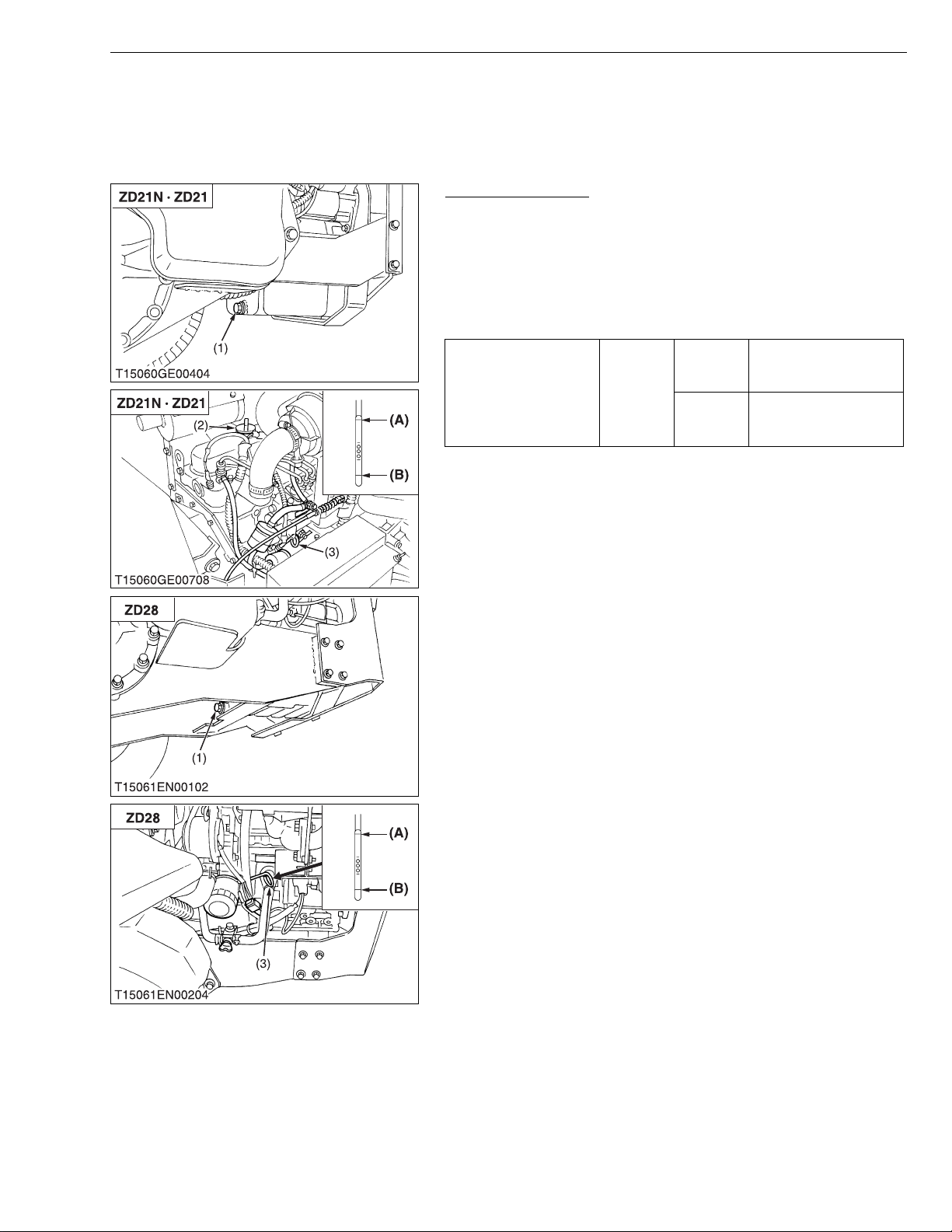
ZD21N-EC, ZD21-EC, ZD28-EC, WSM
IMPORTANT■
KiSC issued 09, 2006 A
5. CHECKING, DISASSEMBLING AND SERVICING
[1] SEPARATING ENGINE
(1) Disassembling and Assembling
Draining Engine Oil
1. Park the machine on level ground.
2. Start and warm up the engine for approx. 5 minutes.
3. Place an oil pan underneath the engine.
4. Remove the drain plug (1) to drain oil.
5. After draining, screw in the drain plug (1).
(When refilling)
• Fill the engine oil up to the upper line on the dipstick (3).
D782
(ZD21N ·
Engine oil Capacity
ZD21)
D1105
(ZD28)
• Never mix two different type of oil.
• Use the proper SAE Engine Oil according to ambient
temperatures.
Refer to “LUBRICANTS, FUEL AND COOLANT”. (See page
G-7.)
(1) Drain Plug
(2) Oil Inlet Plug
(3) Dipstick
(A) Upper Level
(B) Lower Level
3.5 L
3.7 U.S.qts.
3.1 Imp.qts.
3.4 L
3.6 U.S.qts.
3.0 Imp.qts.
ENGINE
W1019220
1-S19
Page 83
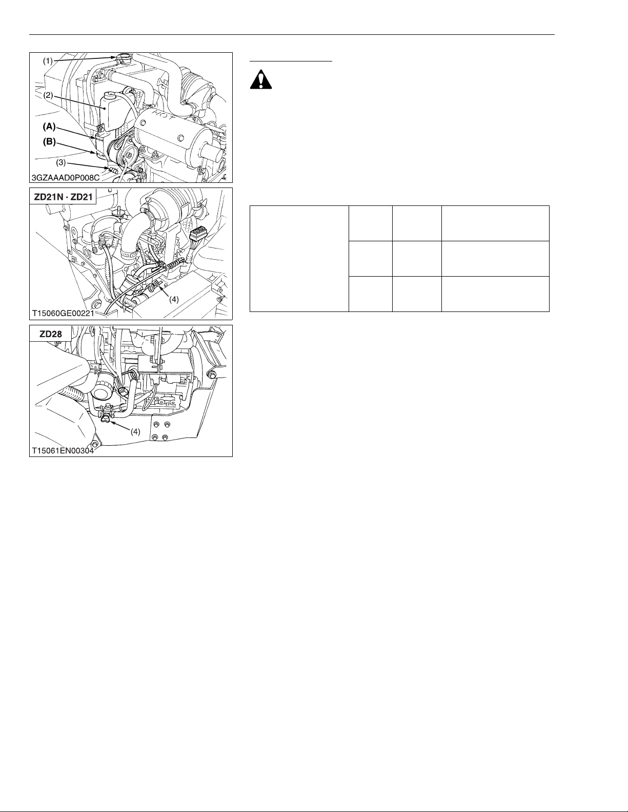
ZD21N-EC, ZD21-EC, ZD28-EC, WSM
KiSC issued 09, 2006 A
ENGINE
Draining Coolant
CAUTION
• Never open the radiat or cap while operating or immedi ately
after stopping. Otherwise, hot water will spout out from the
radiator. Wait for more than ten minutes to cool the radiator,
before opening the cap.
1. Stop the engine and let cool down.
2. Remove the radiator coolant drain plu g (3) and engine cool ant
drain plug (4) to drain the coolant.
3. Remove the radiator cap (1) to completely drain the coolant.
4. After all coolant is drained , close the dr ain plugs.
2.6 L
2.7 U.S.qts.
2.3 lmp.qts.
3.8 L
4.0 U.S.qts.
3.3 lmp.qts
0.25 L
0.26 U.S.qts.
0.22 lmp.qts
Coolant capacity
ZD21N
ZD21
ZD28 Radiator
—
Radiator
Recovery
tank
(1) Radiator Cap
(2) Recovery Tank
(3) Radiator Coolant Drain Plug
(4) Engine Coolant Drain Cock
(A) Upper Level
(B) Lower Level
W1019510
1-S20
Page 84
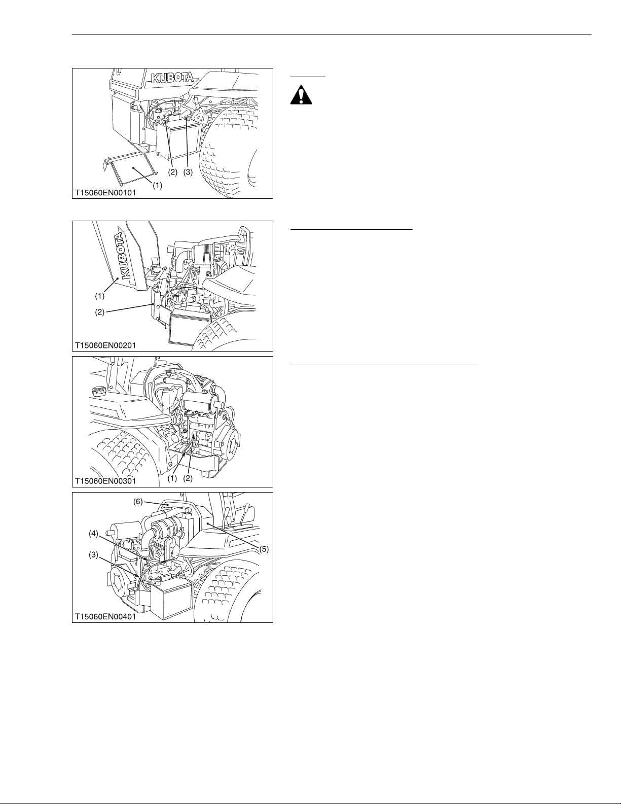
ZD21N-EC, ZD21-EC, ZD28-EC, WSM
■
KiSC issued 09, 2006 A
[ZD21N · ZD21]
ENGINE
Battery
CAUTION
• When disconnecting the battery cables, disconnect the
negative cable from the battery first. When connecting,
connect the positive cable to the battery first.
1. Remove the battery cover (1).
2. Disconnect the negative cable (3) from the battery.
3. Disconnect the positive cable (2) from the battery.
(1) Battery Cover
(2) Positive Cable
(3) Negative Cable
W1019788
Bonnet and Rear Bumper
1. Remove the snap p in and bon net m ountin g screw , then r emove
the bonnet (1).
2. Remove the rear bumper (2).
(1) Bonnet (2) Bumper
W1019921
Panel Screen, Shutter Plate and Others
1. Disconnect the wire har ness (1) and positive cable (2) battery
side first.
2. Disconnect the accelerator wire (3).
3. Disconnect the fuel hoses (4).
4. Remove the panel screen (5) and shutter plate (6).
IMPORTANT
• When disconnecting the fuel hoses, be careful not to let the
fuel spill out the hoses.
(1) Wire Harness
(2) Positive Cable
(3) Accelerator Wire
(4) Fuel Hose
(5) Panel Screen
(6) Shutter Plate
W1033201
1-S21
Page 85
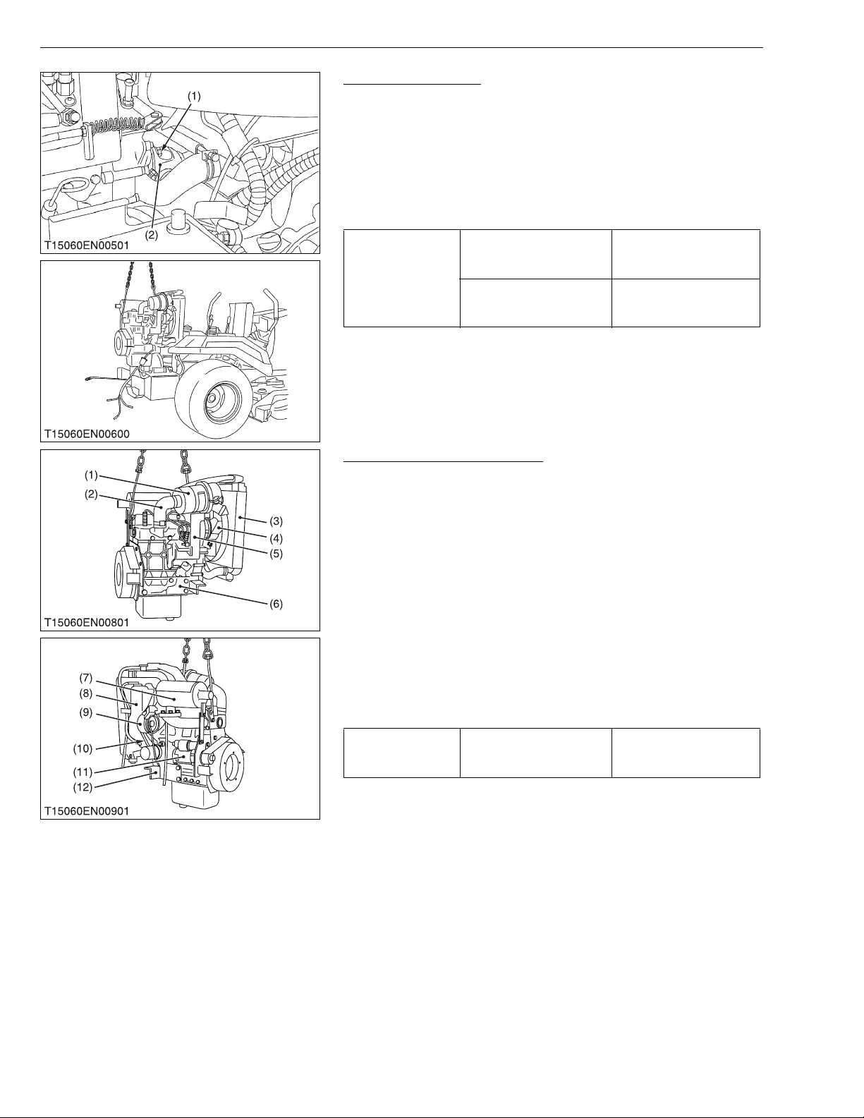
ZD21N-EC, ZD21-EC, ZD28-EC, WSM
IMPORTANT■
KiSC issued 09, 2006 A
ENGINE
Engine Disassembly
1. Remove the universal joint mounting screws (1).
2. Disconnect the universal joint (2) from fun drive pulley.
3. Pull out the snap pins from the radiator.
4. Remove the engine mounting nuts.
5. Separate the engine with th e radiator from the frame, take c are
not to damage the radiator.
(When reassembling)
• Apply grease to the all splines on the drive shaft.
Universal joint mounting
screw
Tightening torque
Engine mounting nut
(1) Universal Joint Mounting Screw (2) Universal Joint
26.0 to 28.0 N·m
2.7 to 2.9 kgf·m
19.2 to 20.7 ft-lbs
23.5 to 27.5 N·m
2.4 to 2.8 kgf·m
17.4 to 20.3 ft-lbs
W1033679
Dynamo, Fan Belt and Muffler
1. Disconnect t he r ad iator hos es an d s epa ra te th e radi ato r (3) with
recovery tank (8) from engine assembly.
2. Remove the co oling fan (4 ) and fan pulley .
3. Remove the dynamo (9) and fan belt (10).
4. Remove the muffler (7).
5. Remove the starter (11).
6. Disconnect th e inlet p ipe (2), ai r cleane r (1) and air cl eaner stay
(5).
7. Remove the wire bracket.
8. Remove the engine support LH (12) and RH (6).
(When reassembling)
• Check to see that there are no cracks on the belt surface.
• After reassembling the fan belt, be sure to adjust the fan belt
tension.
48.1 to 55.9 N·m
4.9 to 5.7 kgf·m
35.4 to 41.2 ft-lbs
Tightening torque
(1) Air Cleaner
(2) Inlet Pipe
(3) Radiator
(4) Cooling Fan
(5) Air Cleaner Stay
(6) Engine Support RH
Engine support mounting
screw
(7) Muffler
(8) Recovery Tank
(9) Dynam o
(10) Fan Belt
(11) Starter
(12) Engine Support LH
1-S22
Page 86
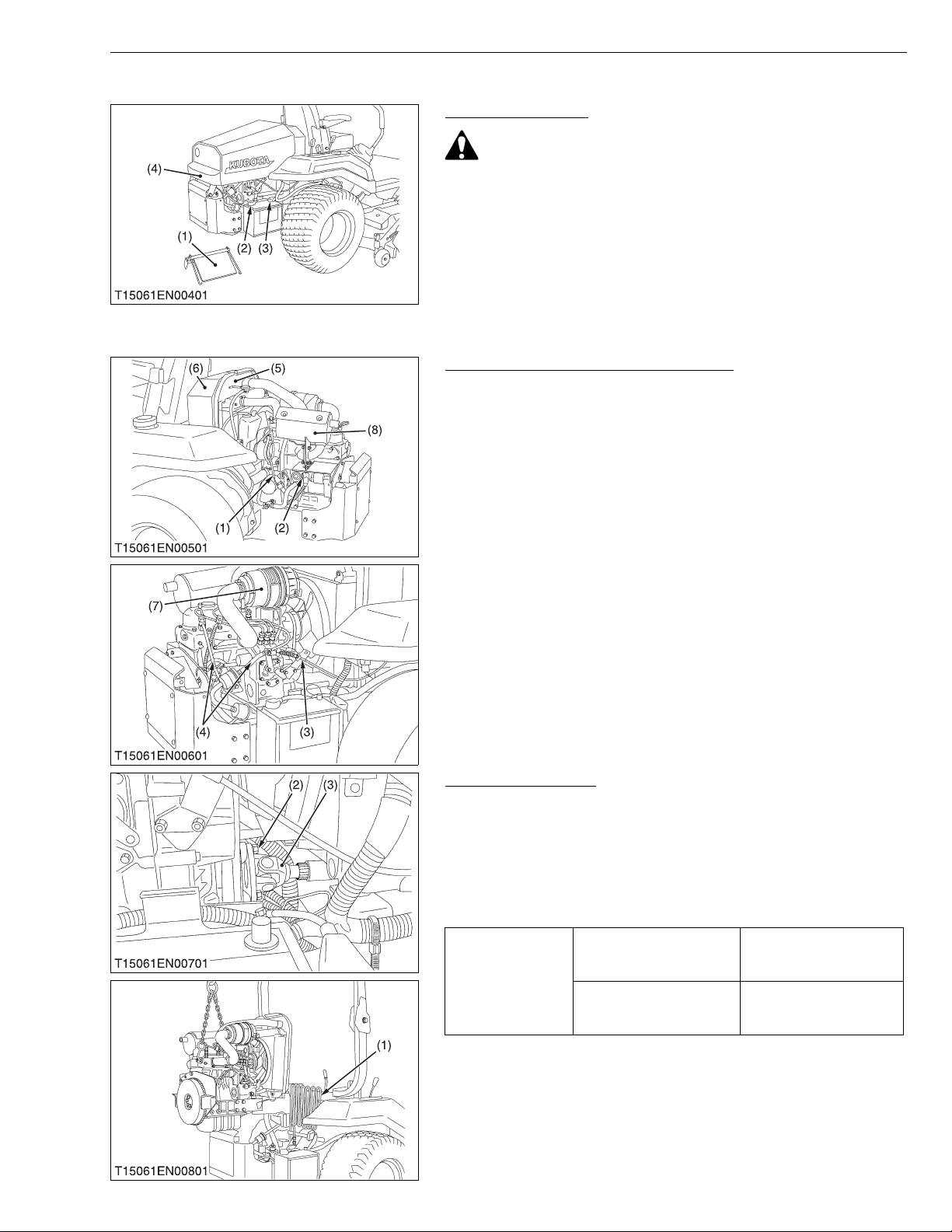
ZD21N-EC, ZD21-EC, ZD28-EC, WSM
■
KiSC issued 09, 2006 A
[ZD28]
ENGINE
Battery and Bonnet
CAUTION
• When disconnecting the battery cables, disconnect the
negative cable from the battery first. When connecting,
connect the positive cable to the battery first.
1. Remove the battery cover (1).
2. Disconnect the negative cable (3) from the battery.
3. Disconnect the positive cable (2) from the battery.
4. Remove the snap p in and bon net m ountin g screw , then r emove
the bonnet (4).
(1) Battery Cover
(2) Positive Cable
(3) Negative Cable
(4) Bonnet
Panel Screen, Shutter Plate and Others
1. Disconnect the glow plug and stop solenoide harness (1) and
positive cable (2) battery side first.
2. Disconnect the accelerator wire (3) and fuse box from shutter
plate (5).
3. Disconnect the fuel hoses (4).
4. Remove the air cleaner (7) and muffler (8).
5. Remove the panel screen (6).
IMPORTANT
• When disconnecting the fuel hoses, be careful not to let the
fuel spill out the hoses.
(1) Wire Harness
(2) Positive Cable
(3) Accelerator Wire
(4) Fuel Hose
(5) Shutter Plate
(6) Panel Screen
(7) Air Cleaner
(8) Muffler
Engine Disassembly
1. Remove the universal joint mounting screws (2).
2. Disconnect the universal joint (3) from fun drive pulley.
3. Remove the engine mounting nuts.
4. Separate the engin e with the ra diator from the frame, take ca re
not to damage the radiator.
(When reassembling)
• Apply grease to the all splines on the drive shaft.
Universal joint mounting
screw
Tightening torque
Engine mounting nut
(1) Oil Cooler
(2) Universal Joint Mounting Screw
(3) Universal Joint
26.0 to 28.0 N·m
2.7 to 2.9 kgf·m
19.2 to 20.7 ft-lbs
23.5 to 27.5 N·m
2.4 to 2.8 kgf·m
17.4 to 20.3 ft-lbs
1-S23
Page 87
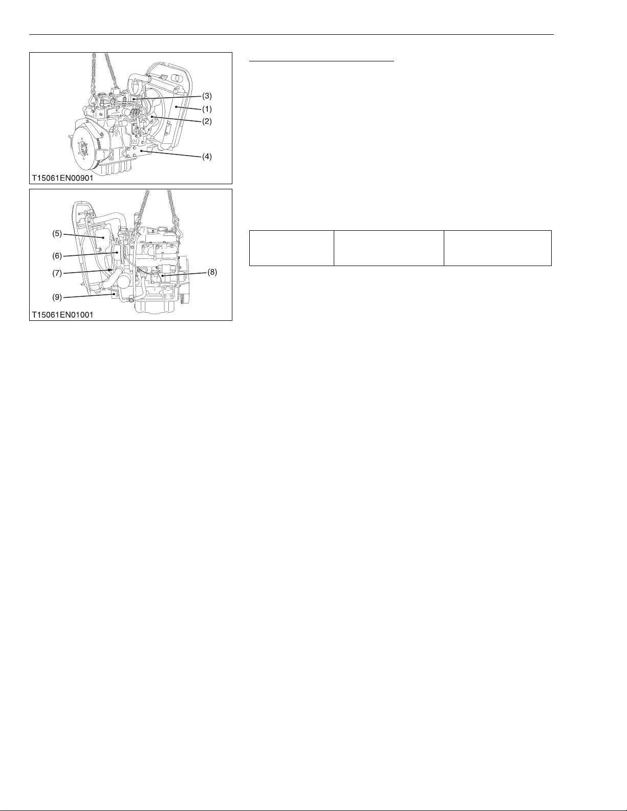
ZD21N-EC, ZD21-EC, ZD28-EC, WSM
IMPORTANT■
KiSC issued 09, 2006 A
ENGINE
Dynamo, Fan Belt and Muffler
1. Disconnect t he r ad iator hos es an d s epa ra te th e radi ato r (1) with
recovery tank (5) from engine assembly.
2. Remove the co oling fan (2 ) and fan pulley .
3. Remove the dynamo (6) and fan belt (7).
4. Remove the starter (8).
5. Remove the air cleaner stay (3).
6. Remove the wire bracket.
7. Remove the engine support LH (9) and RH (4).
(When reassembling)
• Check to see that there are no cracks on the belt surface.
• After reassembling the fan belt, be sure to adjust the fan belt
tension.
48.1 to 55.9 N·m
4.9 to 5.7 kgf·m
35.4 to 41.2 ft-lbs
Tightening torque
Engine support mounting
screw
(1) Radiator
(2) Cooling Fan
(3) Air Cleaner Stay
(4) Engine Support RH
(5) Recovery Tank
(6) Dynamo
(7) Fan Belt
(8) Starter
(9) Engine Support LH
1-S24
Page 88
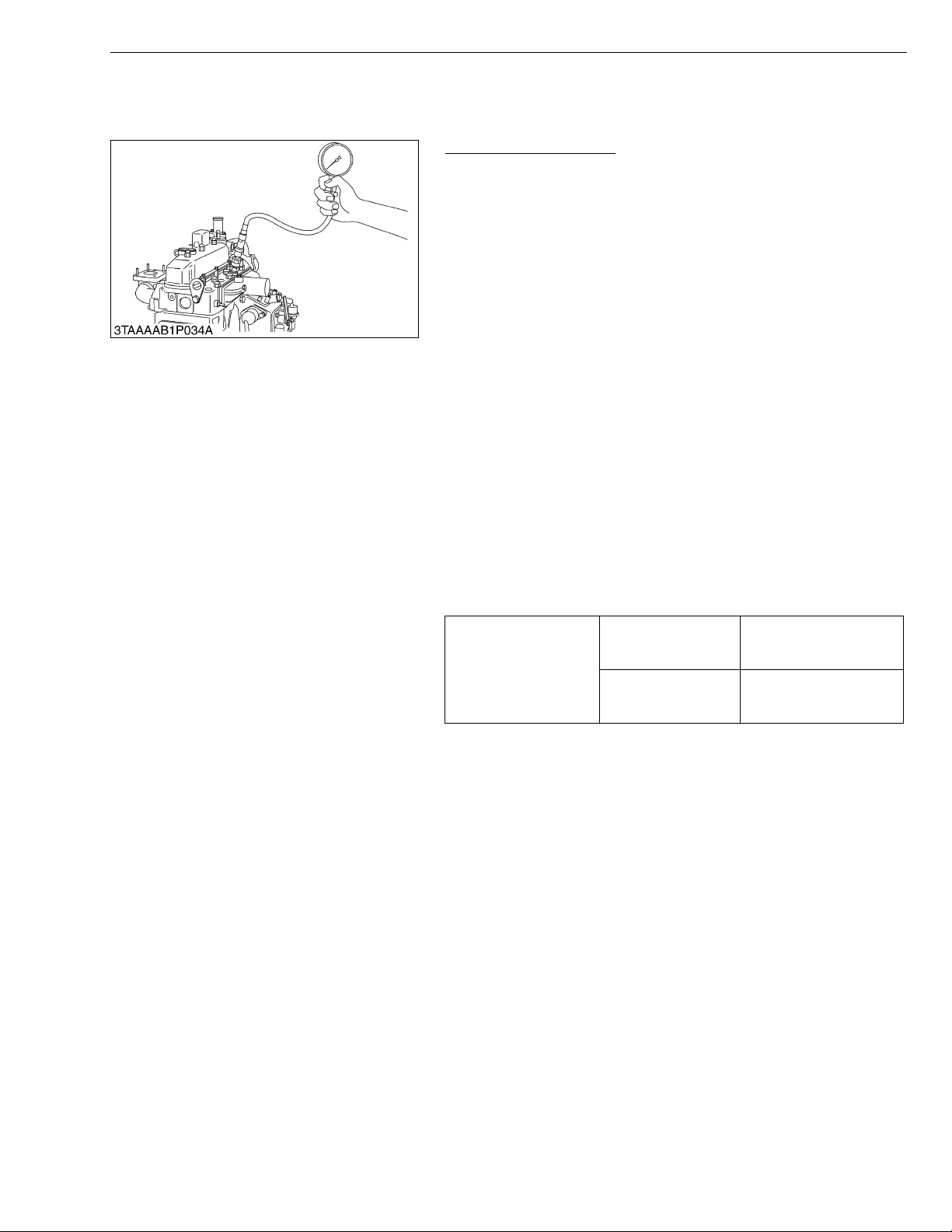
ZD21N-EC, ZD21-EC, ZD28-EC, WSM
NOTE■
KiSC issued 09, 2006 A
[2] ENGINE BODY
(1) Checking and Adjusting
ENGINE
Compression Pressure
1. Run the engine until it is warmed up.
2. Stop the engine.
3. Disconnect the 2P connector from the fuel pump.
4. Remove the air cleaner, the muffler and all injection nozzles.
5. Disconnect the accelerator wire.
6. Engage the parking brake.
7. Set a compression tester (Code No. 07909-30208) with the
adaptor (Adaptor H, Code No. 07909-31231) to the nozzle hole.
8. While cranking the engine with the starter, measure the
compression pressure.
9. Repeat steps 7 and 8 for each cylinder.
10.If the measurem ent is below the allowable limit, apply a small
amount of oil to the cylinder wall through the nozzle hole and
measure the compression pressure again.
11.If the compres sion pressure is still less than the allowabl e limit,
check the top clearance, valve clearance and cylinder head.
12.If the c ompression pressu re increases after a pplying oil, check
the cylinder wall and piston rings.
• Check the compression pressure with the specified valve
clearance.
• Always use a fully charged battery for performing this test.
• Variances in cylinder compression values should be under
10 %.
Compression pressure
Factory spec.
Allowable limit
2.84 to 3.24 MPa
29.0 to 33.0 kgf/cm
412 to 469 psi
2.26 MPa
23.0 kgf/cm
327 psi
2
2
W1022478
1-S25
Page 89
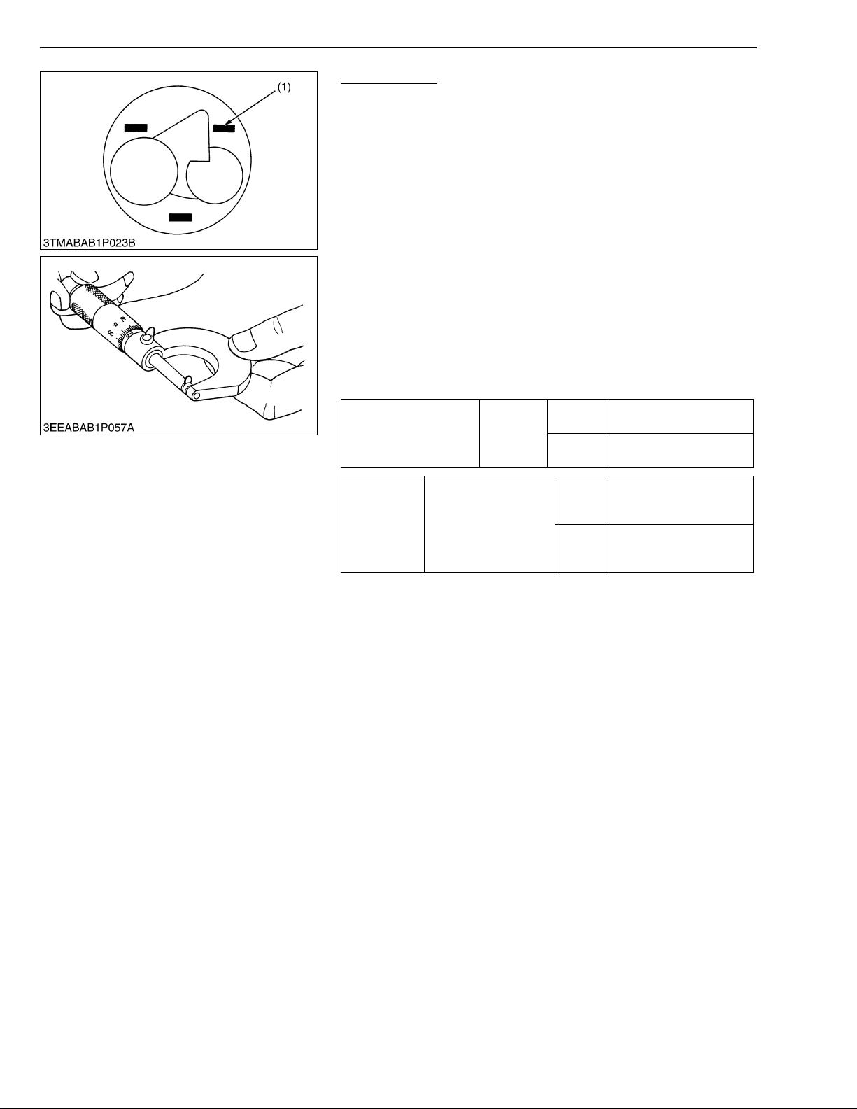
ZD21N-EC, ZD21-EC, ZD28-EC, WSM
NOTE■
KiSC issued 09, 2006 A
ENGINE
Top Clearance
1. Remove the cylinder head (Do not attempt to remove the cylinder
head gasket completely).
2. Bring the pis ton to its top dead cente r fasten 1 .5 mm dia. 5 to 7
mm long fuse wires to 3 to 4 sp ots on the piston top wi th gr ease
so as to avoid the intake and exhaust valves and the combustion
chamber ports.
3. Bring t he piston to its middle positio n, install the cylinder head,
and tighten the cylinder head screws to specification. (Head
gasket must be changed to new one.)
4. Turn the crank shaft until the piston exceeds its top dead center.
5. Remove the cylinder head, and measure the thickness of the
squeezed fuses.
6. If the measurement is not within the factory specifications, check
the oil clearanc e of between the crankpin and crankpin bea ring
and between the piston pin and small end bushing.
• After checking the t op clearance, be sure to assemble the
cylinder head with a new cylinder head gasket.
0.50 to 0.70 mm
0.0197 to 0.0276 in.
0.55 to 0.70 mm
0.0217 to 0.276 in.
Top clearance
Factory
spec.
D782
D1105
Tightening
torque
(1) Fuse
Cylinder head screw
D782
D1105
37.2 to 42.1 N·m
3.8 to 4.3 kgf·m
28.0 to 31.7 ft-lbs
63.7 to 68.6 N·m
6.5 to 7.0 kgf·m
47.0 to 50.6 ft-lbs
W10107670
1-S26
Page 90
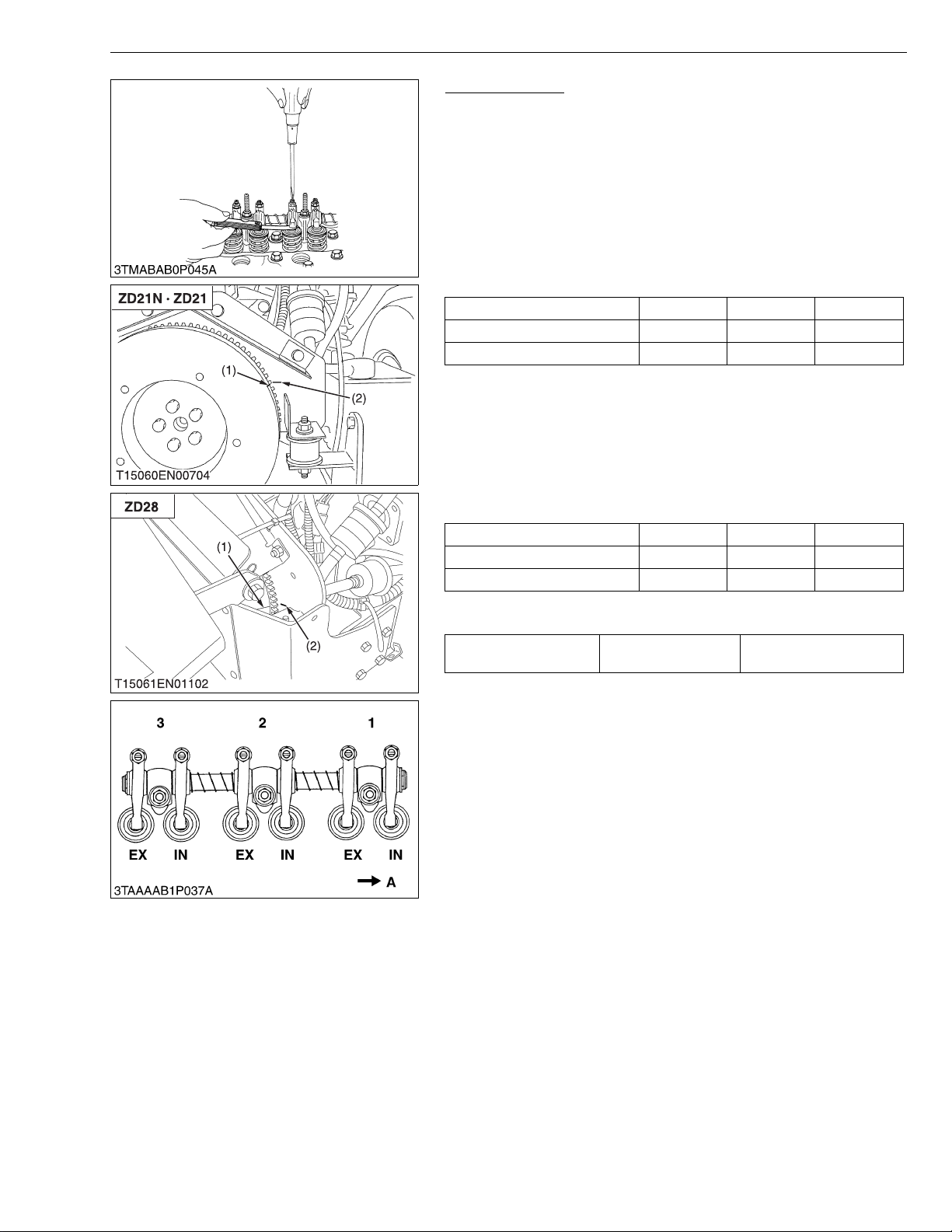
ZD21N-EC, ZD21-EC, ZD28-EC, WSM
IMPORTANT■
NOTE■
KiSC issued 09, 2006 A
ENGINE
Valve Clearance
• The valve clearance must be checked and adjusted when
engine is cold.
1. Remove the cylinder head cover and the glow plugs.
2. Align the “1TC” m ark ( 1) on the flywheel and alignment mark (2)
on the rear end plate so that the No. 1 piston comes to the
compression top dead center.
3. Check the following valve clearance marked with “★” using a
feeler gauge.
[When No. 1 piston comes to the compression top dead center]
Cylinder No. No. 1 No. 2 No. 3
Intake valve ★★
Exhaust valve ★★
4. If the clearance is not within the factory specifications, adjust with
the adjusting screw.
5. Then turn the flywheel 6.28 rad (360°), and align the “1TC” mark
(1) on the flywheel and alig nment mark (2) on the rear end pl ate
so that the No. 1 piston comes to the overlap position.
6. Check the following valve clearance marked with “✩” using a
feeler gauge.
[When No. 1 piston comes to the overlap position]
Cylinder No. No. 1 No. 2 No. 3
Intake valve ✩
Exhaust valve ✩
7. If the clearance is not within the factory specifications, adjust with
the adjusting screw.
Intake and exhaust
valve clearance (Cold)
Factory spec.
0.145 to 0.185 mm
0.00571 to 0.00728 in.
• The sequence of cylinder numbers is given as No. 1, No. 2
and No. 3 starting from the gear case side.
• After adjusting the valve clearance, secure the adjusting
screw with the lock nut.
(1) “1TC” Mark
(2) Alignment Mark
A : Gear Case Side
W10113200
1-S27
Page 91
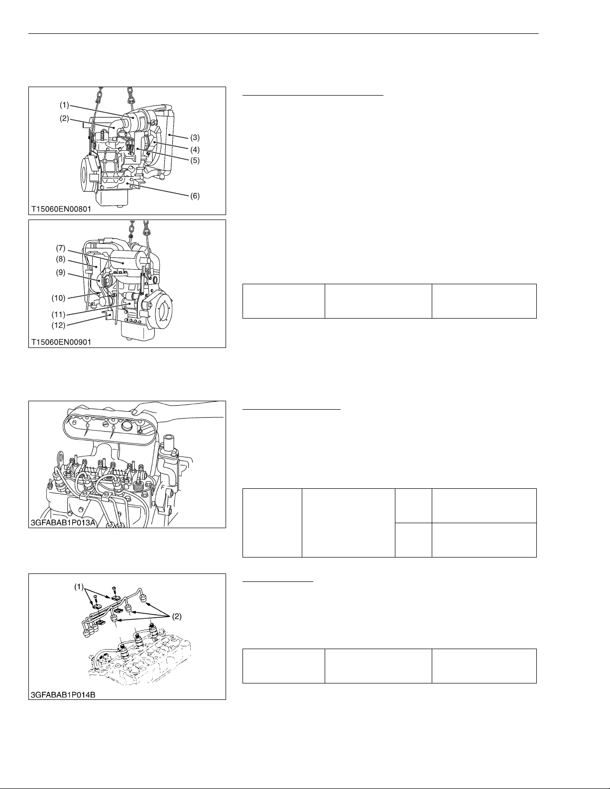
ZD21N-EC, ZD21-EC, ZD28-EC, WSM
IMPORTANT■
KiSC issued 09, 2006 A
(2) Disassembling and Assembling
(A) Cylinder Head and Valves
ENGINE
Dynamo, Fan Belt and Muffler
1. Disconnect t he r ad iator hos es an d s epa ra te th e radi ato r (3) with
recovery tank (8) from engine assembly.
2. Remove the co oling fan (4 ) and fan pulley .
3. Remove the dynamo (9) and fan belt (10).
4. Remove the muffler (7).
5. Remove the starter (11).
6. Disconnect th e inlet p ipe (2), ai r cleane r (1) and air cl eaner stay
(5).
7. Remove the wire bracket.
8. Remove the engine support LH (12) and RH (6).
(When reassembling)
• Check to see that there are no cracks on the belt surface.
• After reassembling the fan belt, be sure to adjust the fan belt
tension.
48.1 to 55.9 N·m
4.9 to 5.7 kgf·m
35.4 to 41.2 ft-lbs
Tightening torque
Engine support mounting
screw
(1) Air Cleaner
(2) Inlet Pipe
(3) Radiator
(4) Cooling Fan
(5) Air Cleaner Stay
(6) Engine Support RH
(7) Muffler
(8) Recovery Tank
(9) Dynam o
(10) Fan Belt
(11) Starter
(12) Engine Support LH
W1024919
Cylinder Head Cover
1. Remove the head cover cap nuts.
2. Remove the cylinder head cover.
(When reassembling)
• Check to see if the cylinder head cover gasket is not defective.
• Apply engine oil to the cylinder head cover cap nuts.
And tighten them.
3.9 to 5.9 N·m
0.4 to 0.6 kgf·m
2.9 to 4.3 ft-lbs
6.9 to 8.8 N·m
0.7 to 0.9 kgf·m
5.1 to 6.5 ft-lbs
W10147380
Tightening
torque
D782
Cylinder head cover
cap nut
D1105
Injection Pipes
1. Loosen the screws on the pipe clamps (1).
2. Detach the injection pipes (2).
(When reassembling)
• Blow out dust from the pipes with compressed air.
Then reassemble the pipes in the reverse order.
Tightening torque Injection pipe retaining nut
24.5 to 34.3 N·m
2.5 to 3.5 kgf·m
18.1 to 25.3 ft-lbs
(1) Pipe Clamp (2) Injection Pipe
W10150780
1-S28
Page 92
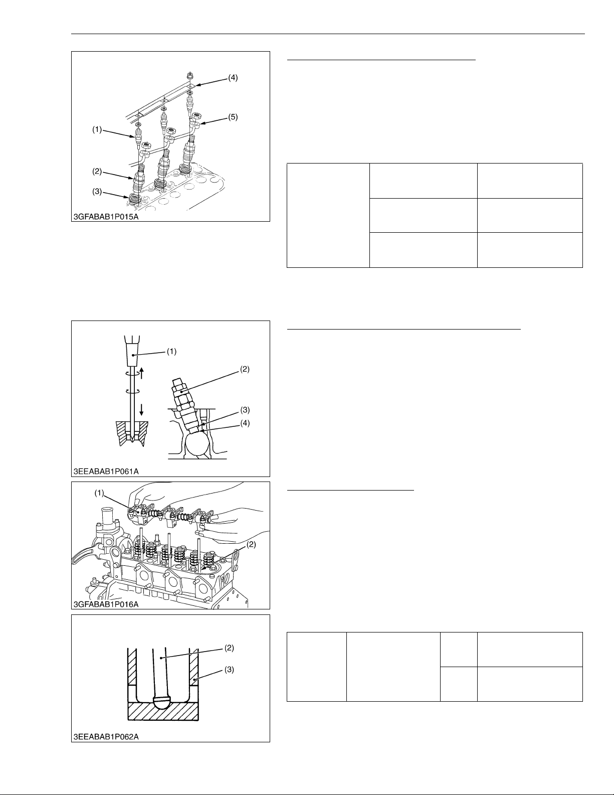
ZD21N-EC, ZD21-EC, ZD28-EC, WSM
■
IMPORTANT■
KiSC issued 09, 2006 A
ENGINE
Nozzle Holder Assembly and Glow Plug
1. Remove the overflow pipe assembly (5).
2. Remove the nozzle holder assembl ies (2) using a 21 mm d eep
socket wrench.
3. Remove the copper gasket and heat seal (3).
4. Remove the lead (4) from the glow plugs.
5. Remove the glow plugs (1).
(When reassembling)
• Replace the copper gasket and heat seal with new one.
49.0 to 68.6 N·m
Tightening torque
Nozzle holder assembly
Overflow pipe assembly
retaining nut
Glow plug
5.0 to 7.0 kgf·m
36.2 to 50.6 ft-lbs
19.6 to 24.5 N·m
2.0 to 2.5 kgf·m
14.5 to 18.1 ft-lbs
7.8 to 14.7 N·m
0.8 to 1.5 kgf·m
5.8 to 10.8 ft-lbs
(1) Glow Plug
(2) Nozzle Holder Assembly
(3) Heat Seal
(4) Lead
(5) Overflow Pipe Assembly
W10259700
Removal Procedure for Nozzle Heat Seal Service
IMPORTANT
• Use a plus (phillips head) screw driver (1) that has a Dia.
bigger than the heat seal hole (Approx. 6 mm) 1/4 in..
1. Drive a screw driver (1) lightly into the heat seal hole.
2. Turn a screw driver three or four times each way.
3. While turning the s crew driver, slowly pull the he at seal (4) out
together with the copper gasket ( 3).
4. If the heat seal drops, repeat the above procedure.
(1) Screw driver (Plus)
(2) Nozzle Holder
(3) Copper Gasket
(4) Heat Seal
W10154410
Rocker Arm and Push Rod
1. Remove the rocker arm bracket nuts.
2. Detach the rocker arm assembly (1).
3. Remove the push rods (2).
(When reassembling)
• When putting the push rods (2) onto the tappets (3), check to see
if their ends are properly engaged with the grooves.
• After installing the rocker arm, be sure to a djust the valve
clearance.
• Apply engine oil to the rocker arm bracket nuts.
And tighten them.
9.8 to 11.3 N·m
1.00 to 1.15 kgf·m
7.2 to 8.3 ft-lbs
21.6 to 26.5 N·m
2.2 to 2.7 kgf·m
15.9 to 19.5 ft-lbs
W10155810
Tightening
torque
(1) Rocker Arm Assembly
(2) Push Rod
Rocker arm bracket
nut
D782
D1105
(3) Tappet
1-S29
Page 93
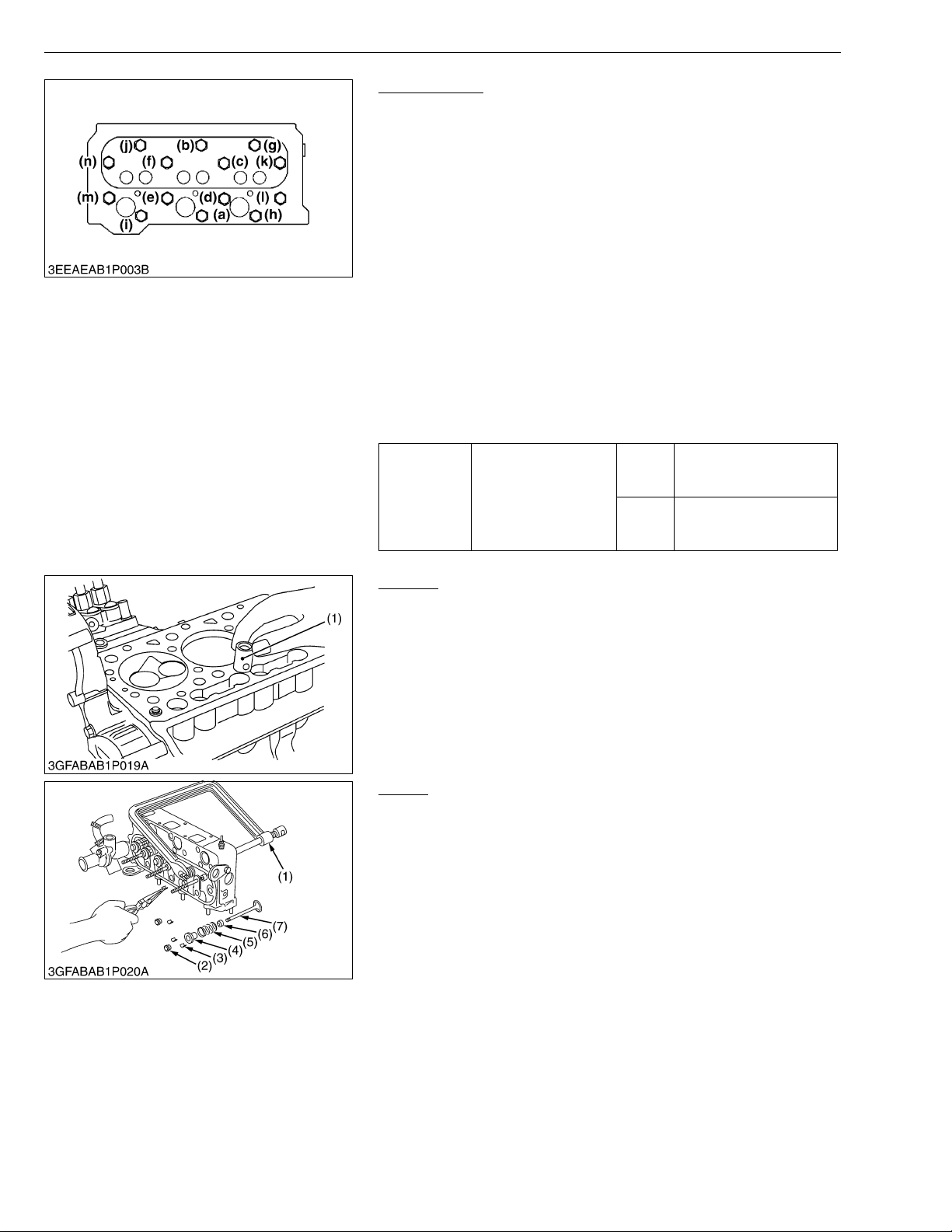
ZD21N-EC, ZD21-EC, ZD28-EC, WSM
NOTE■
IMPORTANT■
IMPORTANT■
KiSC issued 09, 2006 A
ENGINE
Cylinder Head
1. Loosen the pipe clamp, and remove the water return pipe.
2. Remove the cylinder head bolt in the order of (14) to (1).
3. Lift up the cylinder head to detach.
4. Remove the cylinder head gasket and O-ring for carbon sheet
gasket.
(When reassembling)
• Replace the cylinder head gasket with a new one.
• Securely fit the O-ring for carbon sheet gasket to the pipe pin.
• Tighten the cylinder head bolts after applying sufficient oil.
• Tighten the cylinder head bolts in diagonal sequence starting
from the center. (Refer to figure left.)
• Tighten them uniforml y, or the cylinder head may deform in the
long run.
• Retighten the cy linde r head bol ts after r un nin g the eng ine for 30
minutes.
• To Loosen : 14 to 1
• To Tighten : 1 to 14
37.2 to 42.1 N·m
Tightening
torque
D782
Cylinder head screw
D1105
3.8 to 4.3 kgf·m
28.0 to 31.7 ft-lbs
63.7 to 68.6 N·m
6.5 to 7.0 kgf·m
47.0 to 50.6 ft-lbs
W10159710
Tappets
1. Remove the tappets (1) from the crankcase.
(When reassembling)
• Before installing the tappets, apply engine oil thinly around them.
• Mark the cylinder number to the tappets to prevent
interchanging.
(1) Tappet
W1027457
Valves
1. Remove the valve caps (2).
2. Remove the valve spring collet (3), pushing the valve spring
retainer (4) by valve spring replacer (1).
3. Remove the valve spri ng retain er (4 ), valve spri ng (5) an d valv e
stem seal (6).
4. Remove the valve (7).
(When reassembling)
• Wash the va lve s tem and valve g uid e h ole , an d apply engine oi l
sufficiently.
• After installing the valve spring collets, lightly tap the stem to
assure proper fit with a plastic hammer.
• Don’t cha nge the co mbination of valve a nd valve guide.
(1) Valve Spring Replacer
(2) Valve Cap
(3) Valve Spring Collet
(4) Valve Spring Retainer
(5) Valve Spring
(6) Valve Stem Seal
(7) Valve
W10162820
1-S30
Page 94
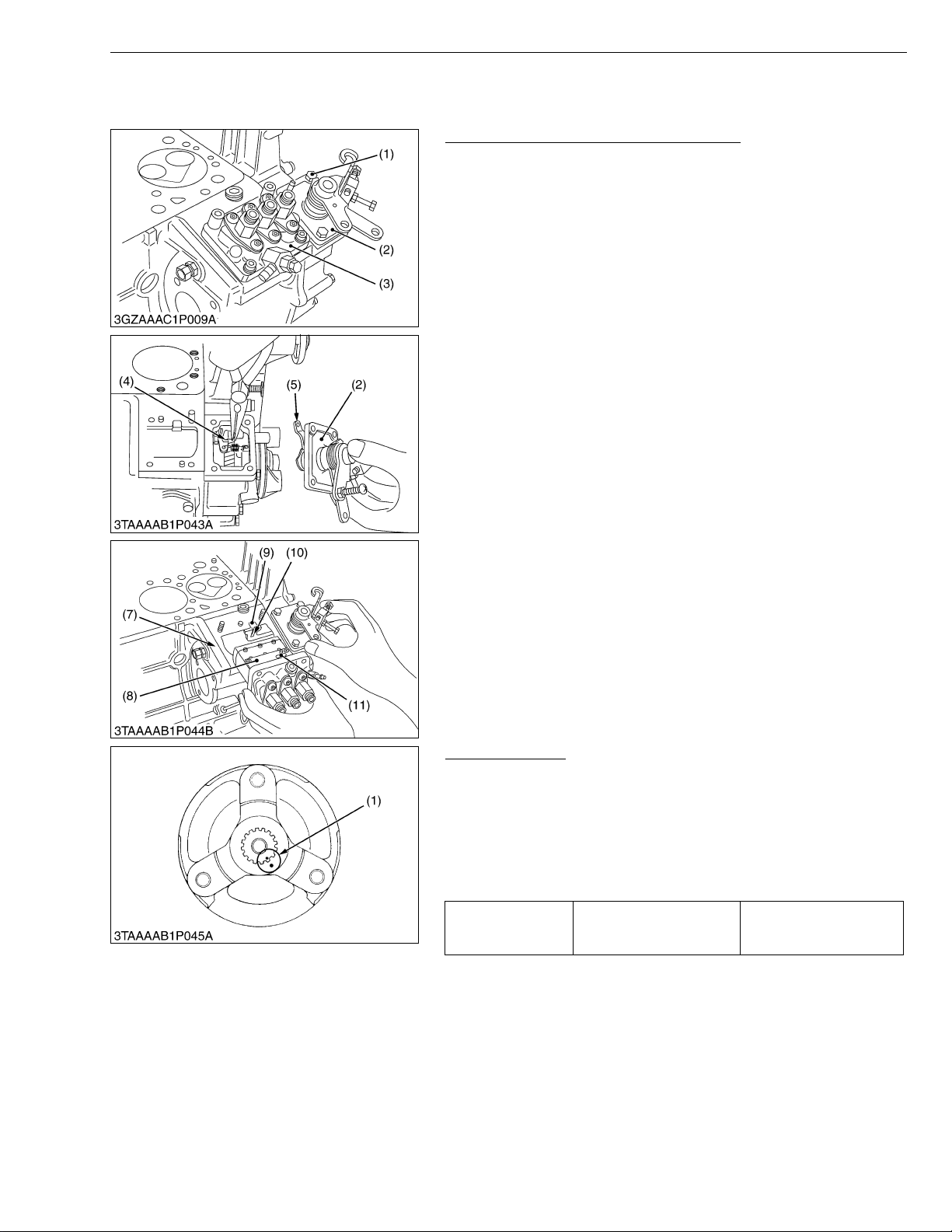
ZD21N-EC, ZD21-EC, ZD28-EC, WSM
■
KiSC issued 09, 2006 A
(B) Timing Gears, Fuel Camshaft and Camshaft
[D782-E-XFM5]
Injection Pump and Speed Control Plate
1. Remove the socket head screws and nuts, and remove the
injection pump (3).
2. Remove the screws and separate the speed control plate (2),
taking care not to damage the spring (4).
3. Disconnect the spring (4) and remove the speed control plate (2).
(When reassembling)
• Hook the spring (4) to the lever (5) first and install the speed
control plate (2).
• Be sure to place the copper washers underneath two screws (1)
(as shown in the figure).
• Position the slot (9) on the fork lever just under the slot (8) on the
crankcase.
• Insert the injection pump (3) so that the control rod (7) should be
pushed by the spring (6) at its end and the pin (10) on the rod
engages with the slot (9) on the fork lever (as shown in the
figure).
NOTE
• The sealant is applied to both sides of the soft metal gasket
shim. The liquid gasket is not required for assembling.
• Addition or reduction of shim (0.05 mm, 0.0020 in.) delays or
advances the injection timing by approx. 0.0087 rad (0.5°).
• In disassembling and replacing, be sure to use the same
number of new gasket shims with the same thickness.
(1) Screws and Copper Washers
(2) Speed Control Plate
(3) Injection Pump
(4) Spring
(5) Lever
ENGINE
(6) Spring
(7) Control Rod
(8) Slot (Crankcase Side)
(9) Slot (Fork Lever Side)
(10) Pin
W10167080
Fan Drive Pulley
1. Set the stopper to the flywheel.
2. Remove the fan drive pulley retaining screw.
3. Draw out the fan drive pulley with a puller.
(When reassembling)
• Install the pulley to the crankshaft, aligning the mark (1) on them.
• Apply engine oil to the fan drive pulley retaining screws.
And tighten them.
Tightening torque
(1) Aligning Mark
Fan drive pulley retaining
screw
117.6 to 127.4 N·m
12.0 to 13.0 kgf·m
86.8 to 94.0 ft-lbs
W10172470
1-S31
Page 95
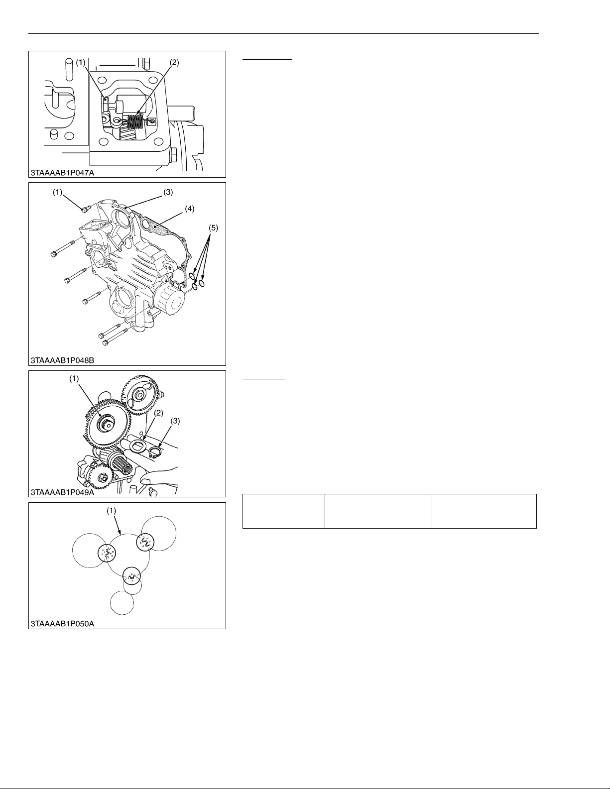
ZD21N-EC, ZD21-EC, ZD28-EC, WSM
KiSC issued 09, 2006 A
ENGINE
Gear Case
1. Remove the screw (1).
2. Disconnect the start spring (2) in the speed control plate
mounting hole.
3. Remove the gear case (3).
(When reassembling)
• Apply a liquid gas ket (Three Bond 1215 or equivalent) to both
sides of the gear case gasket (4).
• Be sure to set three O-rings (5) inside the gear case.
(1) Screw
(2) Start Spring
(3) Gear Case
(4) Gear Case Gasket
(5) O-rings
W10174840
Idle Gear
1. Remove the external snap ring (3), the collar (2) and the idle gear
(1).
2. Remove the idle gear shaft mounting screws.
3. Remove the idle gear shaft.
(When reassembling)
• Install the idl e gear, aligning th e mark on the gears r eferring to
the figure.
• Apply engine oil to the idle gear shaft mounting screws.
And tighten them.
Tightening torque
(1) Idle Gear
(2) Idle Gear Collar
Idle gear shaft mounting
screw
(3) External Snap Ring
9.8 to 11.3 N·m
1.00 to 1.15 kgf·m
7.2 to 8.3 ft-lbs
W1028418
1-S32
Page 96
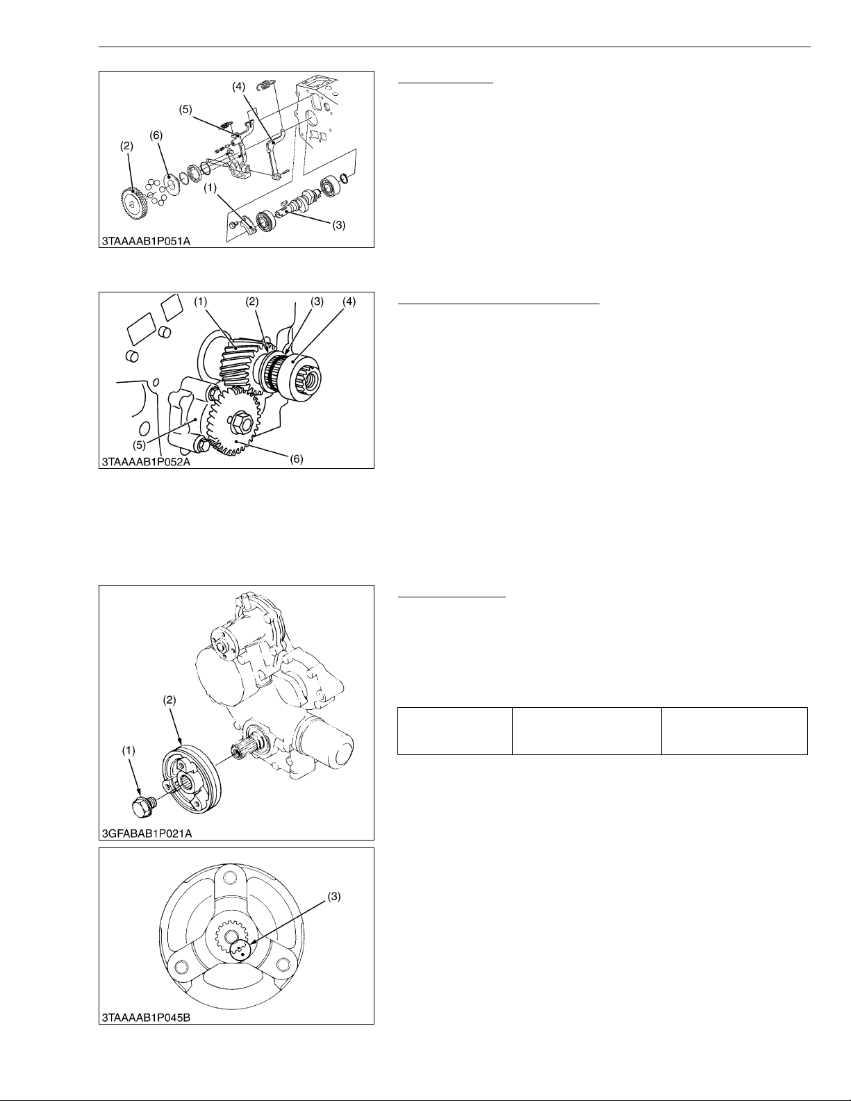
ZD21N-EC, ZD21-EC, ZD28-EC, WSM
KiSC issued 09, 2006 A
ENGINE
Fuel Camshaft
1. Remove the screws and d ra w out t he c amshaft with the gear on
it.
2. Remove the retaining plate (1).
3. Remove the screws, then dra w out the injection pump gear (2)
and fuel camshaft (3) with the governor fork assembly.
(When reassembling)
• Hook the spring to the fork lever 2 (4) as sh own in the figure
before installing the fork lever assembly to the crankcase.
(1) Retaining Plate
(2) Injection Pump Gear
(3) Fuel Camshaft
(4) Fork Lever 2
(5) Fork Lever 1
(6) Governor Sleeve
W10178820
Oil Pump and Crankshaft Gear
1. Remove the oil pump gear (6).
2. Remove the oil pump (5).
3. Remove the collar (4), O-ring (3) and oil slinger (2).
4. Remove the crankshaft gear (1) with a puller.
(When reassembling)
• Install the oil slinger (2) and O-ring (3) after aligning the marks on
the gears. (See the figure at “Idle Gear”.)
• Install the crankshaft collar (4) after installing the gear case
cover.
(1) Crankshaft Gear
(2) Crankshaft Oil Slinger
(3) O-ring
(4) Crankshaft Collar
(5) Oil Pump
(6) Oil Pump Gear
W10180290
(C) Timing Gears, Fuel Camshaft and Camshaft
[D1105-E2-ZD]
Fan Drive Pulley
1. Set the stopper to the flywheel.
2. Remove the fan drive pulley screw (1).
3. Draw out the fan drive pulley (2) with a puller.
(When reassembling)
• Install the fan drive pulley to the cranksha ft, aligning the marks
(3) on them.
Tightening torque
(1) Fan Drive Pulley Screw
(2) Fan Drive Pulley
Fan drive pulley retaining
screw
(3) Aligning Mark
235.4 to 245.2 N·m
24.0 to 25.0 kgf·m
173.6 to 180.8 ft-lbs
W1035250
1-S33
Page 97
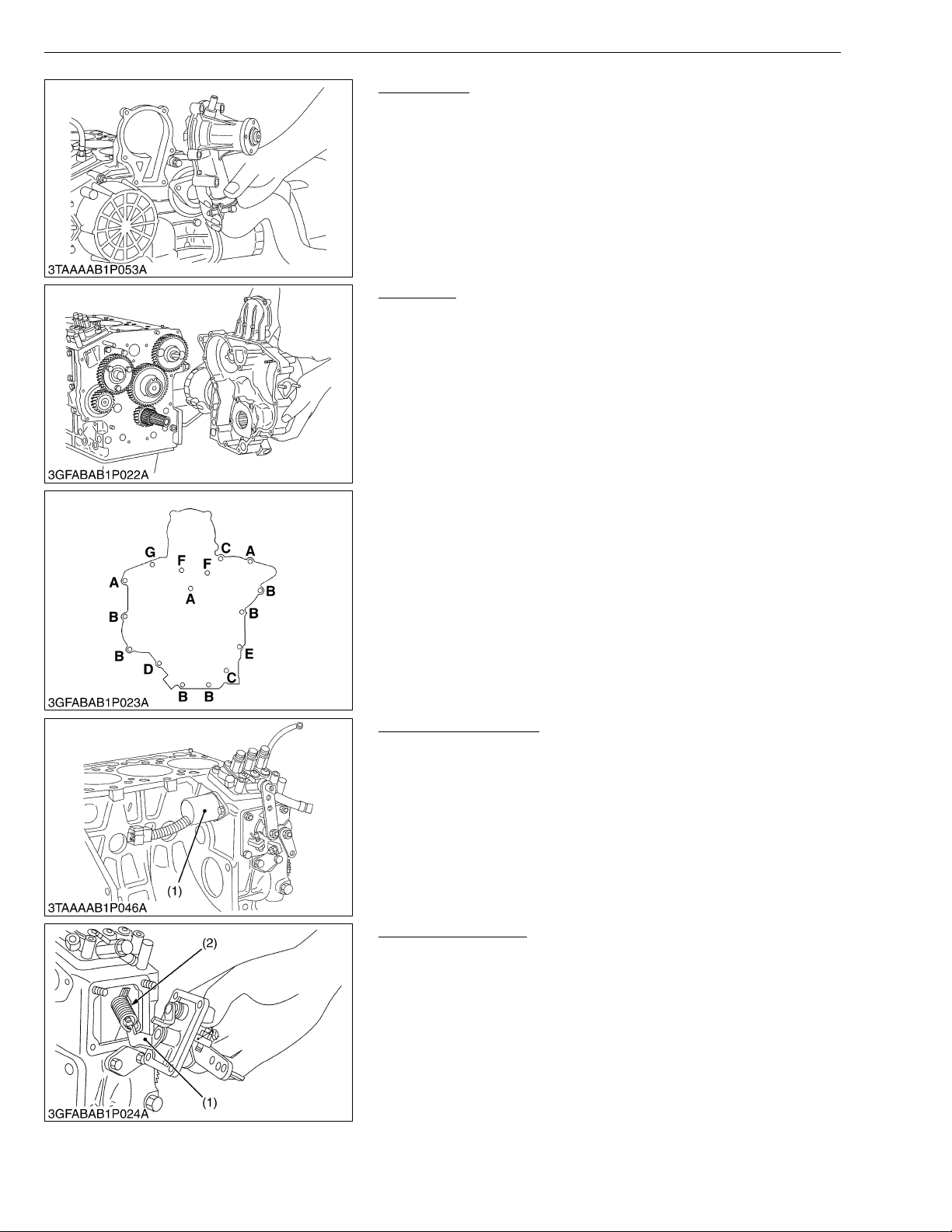
ZD21N-EC, ZD21-EC, ZD28-EC, WSM
KiSC issued 09, 2006 A
ENGINE
Water Pump
1. Remove the water pump flange.
(When reassembling)
• Before installing the water pump flange gasket, apply liquid
gasket (Three Bond 1215 or equivalent) to the both side.
W1035410
Gear Case
1. Remove the gear case.
2. Remove the crankshaft collar and O-rings.
(When reassembling)
• Replace the gear case gasket with a new one.
• Be sure to set the O-ring on the crankshaft.
• Apply a thin f ilm of engine oil to the oil se al, and inst all it, n oting
the lip come off.
• Length of the gear case mounting screws. (Refer to the figure.)
A : 45 mm (1.77 in.)
B : 50 mm (1.97 in.)
C : 55 mm (2.17 in.)
D : 59 mm (2.32 in.)
E : 68 mm (2.68 in.)
F : 80 mm (3.15 in.)
G : Nut
W1035535
Engine Stop Solenoid
1. Remove the engine stop solenoid (1).
(When reassembling)
• Apply a thin coat of liquid-type gasket (Three Bond 1215 or
equivalent) to both surfaces of the solenoid’s cover packing.
• Confirm the convex part of the flange of the engine stop solenoid
has fitted into the hole, and then fasten the bolts.
(1) Engine Stop Solenoid
W1035740
Speed Control Plate
1. Remove the s pee d control plate and governor lever (1) fro m the
governor springs 1 (2).
(When reassembling)
• Securely catch the governor spring on the governor lever as
shown in the figure.
• Apply a liquid gas ket (Three Bond 1215 or equivalent) to both
sides of the speed control plate gas ket .
(1) Governor Lever (2) Governor Spring 1
W1035848
1-S34
Page 98
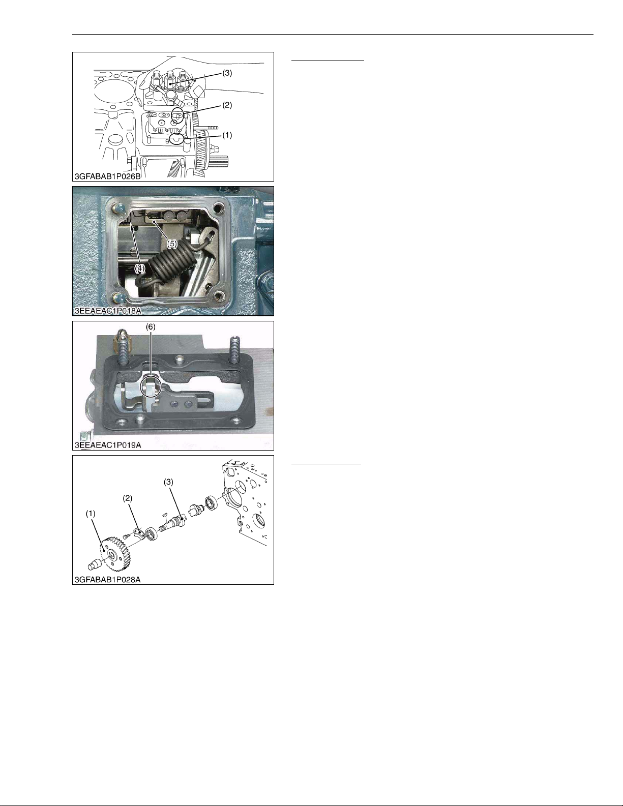
ZD21N-EC, ZD21-EC, ZD28-EC, WSM
NOTE■
KiSC issued 09, 2006 A
ENGINE
Injection Pump
1. Remove the injection pump mounting screws and nuts.
2. Disconnect the start spring (4) on the thrust lever side (5).
3. Align the control rack pin (2) with the notch (1) on the crankcase,
and remove the injection pump (3).
4. Remove the injection pump shims.
5. In principle, the injection pump should not be disassembled.
(When reassembling)
• When installing the injection pump, insert the control rack pin (2)
firmly into the groove (6) of the thrust lever of fork lever.
• The sealant is applied to both sides of the soft metal gasket
shim. The liquid gasket is not required for assembling.
• Addition or reduction of shim (0.05 mm, 0.0020 in.) delays or
advances the injection timing by approx. 0.0087 rad (0.5°).
• In disassembling and replacing, be sure to use the same
number or new gasket shims with the same thickness.
(1) Notch
(2) Control Rack Pin
(3) Injection Pump
(4) Start Spring
(5) Thrust Lever
(6) Groove
W1035956
Fuel Camshaft
1. Remove the fuel camshaft stopper (2).
2. Draw out the fuel camshaft (3) and injection pump gear (1).
(When reassembling)
• Apply engine oil thinly to the fuel camshaft before installation.
(1) Injection Pump Gear
(2) Fuel Camshaft Stopper
(3) Fuel Camshaft
W1036263
1-S35
Page 99
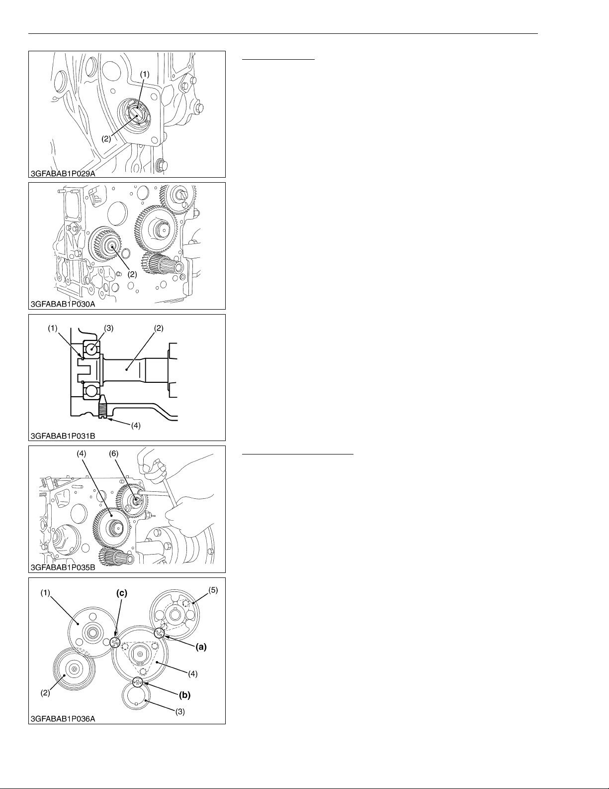
ZD21N-EC, ZD21-EC, ZD28-EC, WSM
IMPORTANT■
KiSC issued 09, 2006 A
ENGINE
Governor Shaft
1. Remove the pump cover.
2. Remove the external snap ring (1) from the governor shaft (2).
3. Pull out the governor shaft (2).
(When reassembling)
• Make sure assembling the external snap ring of the governor
shaft.
• Check the governor shaft for smooth rotation.
• When replacing the ball bearing of governor shaft, securely
fit the ball bearing (3) to the crankc ase, apply an adhesive
(Three Bond 1324B or equivalent) to the set screw (4), and
fasten the screw until its tapered part contacts the
circumferential end of the ball bearing.
(1) External Snap Ring
(2) Governor Shaft
(3) Ball Bearing
(4) Set Screw
W1036385
Camshaft and Idle Gear
1. Remove the external snap ring, a nd then remove the idle gear
(4).
2. Remove the camshaft stopper m ounting s crew, and pu ll out the
camshaf t (6).
(When reassembling)
• When installing the idle gear, be sure to align the alignment
marks (a), (b), (c) on the gears.
• Securely fit the external snap ring and stoppe r.
(1) Injection Pump Gear
(2) Governor Gear
(3) Crank Gear
(4) Idle Gear
(5) Cam Gear
(6) Camshaft
(a) Alignment Mark
(Idle Gear and Cam Gear)
(b) Alignment Mark
(Idle Gear and Crank Gear)
(c) Alignment Mark
(Idle Gear and Injection Pump
Gear)
W1036981
1-S36
Page 100
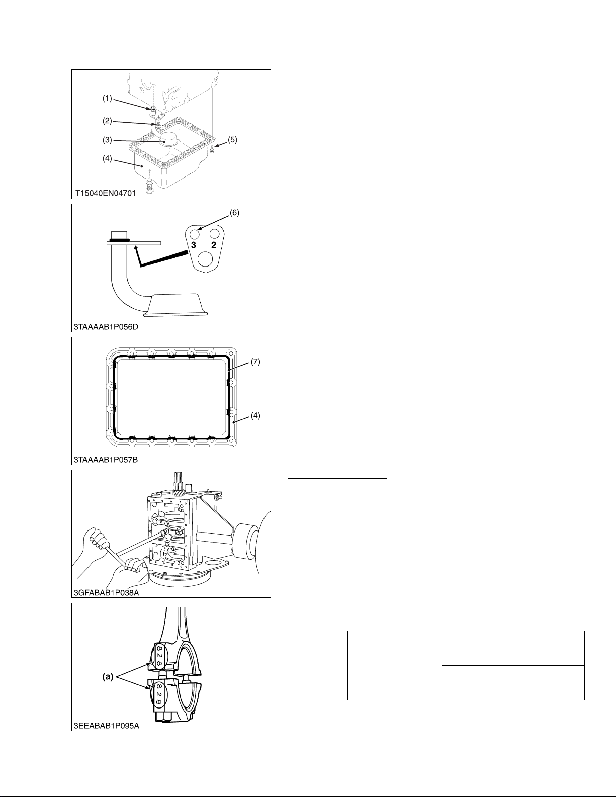
ZD21N-EC, ZD21-EC, ZD28-EC, WSM
IMPORTANT■
KiSC issued 09, 2006 A
(D) Connecting Rod and Piston
ENGINE
Oil Pan and Oil Strainer
1. Remove the oil pan (4).
2. Remove the oil strainer (3).
(When reassembling)
• Install the oil strainer, using care not to damage the O-ring (1).
• Using the hole (6) numbered “3”, install the oil strainer by
mounting screw.
• Apply liquid gask et (Three B ond 1270 D or 1270C ) to the oil pan
as shown in the figure.
• Scrape off the old adhesive completely. Wipe the sealing
surface clean using waste cloth soaked with gasoline.
Now apply new adhesive 3 to 5 mm (0.12 to 0.20 in.) thick all
over the contact surface. App ly the adhesive also on the
center of the flange as wel l as on the inne r w all o f each bolt
hole.
• Cut the nozzl e of t he “f luid sealan t” co ntain er at i ts se cond
notch. Apply “fluid sealant” about 5 mm (0.20 in.) thick.
Within 20 minutes after the application of fluid sealant,
reassemble the components. Wait then for about 30
minutes, and pour oil in the crankcase.
(1) O-ring
(2) Screw
(3) Oil Strainer
(4) Oil Pan
(5) Oil Pan Mounting Screws
(6) Hole
(7) Fluid sealant
W10265670
Connecting Rod Cap
1. Remove the connecting rod screws from connecting rod cap.
2. Remove the connecting rod caps.
(When reassembling)
•Align the marks (a) with each other. (Face the marks toward the
injection pump.)
• Apply engine oil to the connecting rod screws and lightly screw it
in by hand, then tighten it to the specified torque.
If the connecting ro d screw won’t be screwed in smo othl y , cl ean
the threads.
If the connecting rod screw is still hard to screw in, replace it.
• Do not change the combination of crankpin bearing and
connecting rod.
26.5 to 30.4 N·m
2.7 to 3.1 kgf·m
19.5 to 22.4 ft-lbs
41.2 to 46.1 N·m
4.2 to 4.7 kgf·m
30.4 to 34.0 ft-lbs
W10275480
Tightening
torque
(a) Mark
D782
Connecting rod screw
D1105
1-S37
 Loading...