

Page 1

WORKSHOP MANUAL
KiSC issued 11, 2006 A
TRACTOR
STα-30,STα-35
Page 2

TO THE READER
KiSC issued 11, 2006 A
This Workshop Manual has been prepared to provide servicing personnel with
information on t he mechanism, service and maintenance of KUBOTA T ractor STα-30
and STα-35. It is divided into two parts, “Mechanism” and “Servicing” for each section.
■ Mechanism
Information on the construction and function are included. This part should be
understood before proceeding with troubleshooting, disassembling and servicing.
■ Servicing
Under the heading “General” section comes general precautions, check and
maintenance and special tools. Other section, there are troubleshooting, servicing
specification lists, checking and adjusting, disassembling and assembling, and servicing
which cover procedures, pr ecauti ons , fac tor y spe cifi ca tion s and allowa bl e limits .
All information illustrations and specifications contained in this manual are based on
the latest production information available at the time of publication.
The right is reserved to make changes in all information at any time without notice
September 2000
© KUBOTA Corporation 2000
Page 3

STα-30 · STα-35, WSM
SAFETY FIRST
KiSC issued 11, 2006 A
SAFETY INSTRUCTIONS
SAFETY INSTRUCTIONS
This symbol, the industry’s “Safety Alert Symbol”, is used throughout this manual and decals on the
machine itself to warn of the possibility of personal injury. Read these instructions carefully.
It is essential that you read the instructions and safety regulations before you attempt to repair or use
this unit.
DANGER : Indicates an imminently hazardous situation which, if not avoided, will result in
death or serious injury.
WARNING : Indicates a potentially hazardous situation which, if not avoided, could result in
death or serious injury.
CAUTION : Indicates a potentially hazardous situation which, if not avoided, may result in
minor or moderate injury.
■ IMPORTANT : Indicates that equipment or property damage could result if instructions are not
followed.
■ NOTE : Gives helpful information.
BEFORE SERVICING AND REPAIRING
• Read all instructions and safety instructions in this
manual and on your machine safety decals.
• Clean the work area and machine.
• Park the machine on a firm and level ground, and set
the parking brake.
• Lower the implement to the ground.
• Stop the engine, and remove the key.
• Disconnect the battery negative cable.
• Hang a “DO NOT OPERATE” tag in operator station.
1
Page 4

STα-30 · STα-35, WSM
KiSC issued 11, 2006 A
SAFETY INSTRUCTIONS
SAFETY STARTING
• Do not start the engine by shorting across starter
terminals or bypassing the safety start switch.
• Do not alter or remove any part of machine safety
system.
• Before starting the engine, make sure that all shift
levers are in neutral positions or in disengaged
positions.
• Never start the engine while standing on ground.
Start the engine only from operator’s seat.
SAFETY WORKING
• Do not work on the machine while under the influence
of alcohol, medication , or other substances or while
fatigued.
• Wear close fitting clothing and safety equipment
appropriate to the job.
• Use tools appropriate to the work. Markshift tools,
parts, and procedures are not recommended.
• When servicing is performed together by two or more
persons, take care to perform all work safely.
• Do not work under the machine that is supported
solely by a jack. Always support the machine by
safety stands.
• Do not touch the rotating or hot parts while the engine
is running.
• Never remove the radiator cap while the engine is
running, or immediately after stopping. Otherwise,
hot water will spout out fr om radiator. Only remove
radiator cap when cool enough to touch with bare
hands. Slowly loosen the cap to first stop to relieve
pressure before removing completely.
• Escaping fluid (fuel or hydraulic oil) un der pressure
can penetrate the skin causing serious injury. Relieve
pressure before disconnecting hydraulic or fuel lines.
Tighten all connections before applying pressure.
AVOID FIRES
• Fuel is extremely flammable and explosive under
certain condition s. Do not smoke or allow flames o r
sparks in your working area.
• To avoid sparks from an accidental short circuit,
always disconnect the battery negative cable first and
connect it last.
• Battery gas can explode. Keep sparks and open
flame away from the top of b attery, especially when
charging the battery.
• Mark sure that no fuel has been spilled on the engine.
2
Page 5

STα-30 · STα-35, WSM
KiSC issued 11, 2006 A
SAFETY INSTRUCTIONS
VENTILATE WORK AREA
• If the engine must be running to do some work, make
sure the area is well ventilated. Never run the engine
in a closed area. The exhaust gas contains
poisonous carbon monoxide.
PREVENT ACID BURNS
• Sulfuric acid in battery electr olyte is po isonous. It is
strong enough to burn skin, clothing and cause
blindness if splashed into eyes. Keep electrolyte
away from eyes, hands and clothing. If you spill
electrolyte on yourself, flush with water, and get
medical attention immediately.
DISPOSE OF FLUIDS PROPERLY
• Do not pour fluids into the ground, down a drain, or
into a stream, pond, or lake. Observe relevant
environmental prot ectio n regulati ons whe n disp osing
of oil, fuel, coolant, electrolyte and other harmful
waste.
PREPARE FOR EMERGENCIES
• Keep a first aid kit and fire extingui sher handy at all
times.
• Keep emergency numbers for doctors, ambulance
service, hospital and fire department near your
telephone.
3
Page 6

STα-30 · STα-35, WSM
KiSC issued 11, 2006 A
SAFETY INSTRUCTIONS
SAFETY DECALS
The following safety decals are installed on the machine.
If a decal becomes damaged, illegible or is not on the machine, replace it. The decal part number is listed in
the parts list.
4
Page 7

STα-30 · STα-35, WSM
KiSC issued 11, 2006 A
SAFETY INSTRUCTIONS
5
Page 8

STα-30 · STα-35, WSM
KiSC issued 11, 2006 A
SAFETY INSTRUCTIONS
6
Page 9

STα-30 · STα-35, WSM
KiSC issued 11, 2006 A
SPECIFICATIONS
Model STα-30 STα-35
PTO power 17.3 kW (23.5 PS) 21.0 kW (28.5 PS)
Maker KUBOTA
Model D1463-M-ST D1703-M-ST
Type ETVCS, Indirect Injection. Vertical, water-cooled, 4-cycle diesel
Number of cylinders 3
Bore and stroke 82 × 92.4 mm (3.23 × 3.64 in.) 87 × 92.4 mm (3.43 × 3.64 in.)
Total displacement 1463 cm
Engine net power
Engine
Capacities
Tires
Dimensions
Weight (with ROPS)
Minimum turning radius
(with bi-speed turn)
Clutch Dry single plate
(ECE-R24)
SAE gross 22.4 kW (30 HP) 26.8 kW (35.9 HP)
Rated revolution 45 r/s (2700 min
Maximum to rque 96.5 N·m (9.85 kgf·m) / 1500 min
Battery 12 V, RC : 110 min, CCA : 550 A
Starting system Electric starting with cell starter 12 V, 1.4 kW
Lubricating system Forced lubrication by trochoidal pump
Cooling system Pressurized radiator, forced circulation with water pump
Fuel Diesel fuel No. 2-D [above −10 °C (14 °F)], Diesel fuel No. 1 [below −10 °C (14 °F]
Fuel tank 29.5 L (7.79 U.S.gals., 6.49 Imp.gals.)
Engine crankcase
(with filter)
Engine coolant
(with recovery tank)
Transmission case 18.5 L (4.89 U.S.gals., 4.07 Imp.gals.)
Front axle case 4.0 L (1.06 U.S.gals., 0.88 Imp.gals.)
Front
Rear 12.4-16 9.5-22 13.6-16 12.4-16 9.5-22 13.6-16
Overall length (with 3P) 2870 mm (113 in.)
Overall width (minimum
tread)
Overall height (with
ROPS)
Wheel base 1610 mm (63.4 in.)
Minimum ground
clearance (Mid-PTO
case)
Front 1020 mm (40.2 in.)
Tread
Rear
with brake 2.2 m (7.2 feet)
without
brake
Farm
6-12
1465 mm
(57.7 in.)
2330 mm
(91.7 in.)
215 mm
(8.5 in.)
1148 mm
(45.2 in.)
975 kg
(2150 lbs)
3
(89.28 cu.in.) 1647 cm3 (100.51 cu.in.)
21.2 kW 25.5 kW
-1
(rpm))
-1
(rpm)) 111 N·m (11.3 kgf·m) / 1500 min-1 (rpm))
4.5 L (1.19 U.S.gals., 0.99 Imp.gals.)
5.8 L (1.56 U.S.gals., 1.28 Imp.gals.)
Farm
6.00-12
1220 mm
(48.1 in.)
2350 mm
(92.5 in.)
235 mm
(9.3 in.)
950, 1070 mm
(37.4, 42.1 in.)
965 kg
(2130 lbs)
Turf
24 × 8.50-14
1310 mm
(51.6 in.)
2345 mm
(92.3 in.)
230 mm
(9.1 in.)
965, 1055 mm
(38.0, 41.5 in.)
985 kg
(2170 lbs)
2.5 m (8.2 feet)
Farm
6-12
1465 mm
(57.7 in.)
2330 mm
(91.7 in.)
215 mm
(8.5 in.)
1148 mm
(45.2 in.)
975 kg
(2150 lbs)
Farm
6.00-12
1220 mm
(48.1 in.)
2350 mm
(92.5 in.)
235 mm
(9.3 in.)
950, 1070 mm
(37.4, 42.1 in.)
965 kg
(2130 lbs)
SPECIFICATIONS
Turf
24 × 8.50-14
1310 mm
(51.6 in.)
2345 mm
(92.3 in.)
230 mm
(9.1 in.)
965, 1055 mm
(38.0, 41.5 in.)
985 kg
(2170 lbs)
W1028117
7
Page 10

STα-30 · STα-35, WSM
KiSC issued 11, 2006 A
Model STα-30 STα-35
Steering Hydrostatic power steering
Pump capacity (power
Travelling
system
Hydraulic
system
PTO system
Note : * Manufacture’s estimate the company reserves the right to change the specifications without notice.
steering)
Transmission Main-hydrostatic transmission, range gear shift (3 forward and 3 reverse)
Brake Wet disk type
Differential Bevel gear
Hydraulic control system Position control
Pump capacity 23 L/min. (6.1 U.S.gals./min., 5.1 Imp.gals./min.)
Three point hitch SAE Category I
At lift points 1150 kg (2535 lbs)
Max. lift
force
Rear
Mid.
24 in.
behind lift
points
PTO shaft S AE 1-3/ 8, 6 splines
Revolution 540 / 2673 min
PTO shaft USA No. 5 (KUBOTA 10-tooth) involute spline
Revolution 1700 / 2710 min
14.0 L/min. (3.7 U.S.gals./min., 3.1 Imp.gals./min.)
890 kg (1962 lbs)
-1
(rpm), 800 / 2738 min-1 (rpm)
-1
(rpm), 2500 / 2755 min-1 (rpm)
SPECIFICATIONS
W1031009
8
Page 11

STα-30 · STα-35, WSM
KiSC issued 11, 2006 A
TRAVELLING SPEED
TRAVELLING SPEED
Model STα-30 · STα-35
Tire size (Rear) 9.5-22 12.4-16 13.6-16
Range gear shift lever km/h (mile/h) km/h (mile/h) km/h (mile/h)
1 (Low) 0 to 6.6 (0 to 4.1) 0 to 6.3 (0 to 3.9) 0 to 6.5 (0 to 4.0)
Forward
(At rated engine rpm)
Reverse
(At rated engine rpm)
The company reserves the right to change the spe cifi ca tion s with out notic e.
2 (Middle) 0 to 12.7 (0 to 7.9) 0 to 12.2 (0 to 7.6) 0 to 12.6 (0 to 7.8)
3 (High) 0 to 28.4 (0 to 17.6) 0 to 27.2 (0 to 17.0) 0 to 28.2 (0 to 17.5)
Max. Speed
(at 2850 engine rpm)
1 (Low) 0 to 4.8 (0 to 3.0) 0 to 4.6 (0 to 2.9) 0 to 4.7 (0 to 2.9)
2 (Middle) 0 to 9.2 (0 to 5.7) 0 to 8.8 (0 to 5.5) 0 to 9.2 (0 to 5.7)
3 (High) 0 to 20.6 (0 to 12.8) 0 to 19.7 (0 to 12.2) 0 to 20.4 (0 to 12.7)
Max. Speed
(at 2850 engine rpm)
29.9 (18.6) 28.7 (17.8) 29.8 (18.5)
21.7 (13.5) 20.8 (12.9) 21.6 (13.4)
W1035065
9
Page 12

STα-30 · STα-35, WSM
KiSC issued 11, 2006 A
DIMENSIONS
DIMENSIONS
10
Page 13

G GENERAL
KiSC issued 11, 2006 A
Page 14

GENERAL
KiSC issued 11, 2006 A
CONTENTS
1. FEATURES...................................................................................................... G-1
2. TRACTOR IDENTIFICATION ......................................................................... G-2
3. GENERAL PRECAUTIONS ............................................................................ G-3
4. HANDLING PRECAUTIONS FOR ELECTRICAL PARTS AND WIRING..G-4
[1] WIRING...................................................................................................... G-4
[2] BATTERY................................................................................................... G-6
[3] FUSE.......................................................................................................... G-6
[4] CONNECTOR............................................................................................ G-6
[5] HANDLING OF CIRCUIT TESTER......................................................... G-7
5. LUBRICANTS FUEL AND COOLANT .......................................................... G-8
6. TIGHTENING TORQUES ............................. ....... ...... ....... ...... ....... ...... ....... .... G- 9
[1] GENERAL USE SCREWS, BOLTS AND NUTS................................... G-9
[2] STUD BOLTS............................................................................................ G-9
7. MAINTENANCE............................................................................................. G-10
8. CHECK AND MAINTENANCE......... ...... ...... ....... ...... ....... ...... ....... ............... G-11
[1] DAILY CHECK........................................................................................ G-11
[2] CHECK POINTS OF INITIAL 50 HOURS........................................... G-12
[3] CHECK POINTS OF EVERY 50 HOURS........................................... G-15
[4] CHECK POINTS OF EVERY 100 HOURS......................................... G-17
[5] CHECK POINTS OF EVERY 200 HOURS......................................... G-22
[6] CHECK POINTS OF EVERY 400 HOURS......................................... G-24
[7] CHECK POINTS OF EVERY 600 HOURS......................................... G-24
[8] CHECK POINTS OF EVERY 800 HOURS......................................... G-25
[9] CHECK POINTS OF EVERY 1 YEAR ................................................ G-25
[10]CHECK POINTS OF EVERY 2 YEARS.............................................. G-25
[11]OTHERS .................................................................................................. G-28
9. SPECIAL TOOLS.......................................................................................... G-30
[1] SPECIAL TOOLS FOR ENGINE .......................................................... G-30
[2] SPECIAL TOOLS FOR TRACTOR....................................................... G-36
10. TIRES............................................................................................................. G-39
[1] TIRE PRESSURE................................................................................... G-39
[2] TREAD..................................................................................................... G-39
(1) Front Wheels...................................................................................... G-40
(2) Rear Wheels ...................................................................................... G-40
[3] TIRE LIQUID INJECTION...................................................................... G-41
11. IMPLEMENT LIMITATIONS.......................................................................... G-43
Page 15

STα-30 · STα-35, WSM
KiSC issued 11, 2006 A
1. FEATURES
G GENERAL
1. Hydraulic Power Steering
2. E-TVCS (Three Vortex Combustion System) Diesel Engine
3. Engine Key Shut-Off System
4. Hydrostatic Transmission (HST)
5. 3 Range of Speed
6. Bi-speed Turn
7. Cruise Control
8. Wet Disc Brake
9. Standard mid -PT O
10.Simultaneous Mounting of Both the Mid. Mount Mower and Front Loader
11.Combination Panel of Easy Checker
12.Large Hydraulic Pump
13.Position Control Valve
14.Hydraulic Block Type Outlet
15.Foldable ROPS
G-1
Page 16

STα-30 · STα-35, WSM
KiSC issued 11, 2006 A
2. TRACTOR IDENTIFICATION
When contacting your local KUBOTA distributor, always specify
engine serial number, tractor serial number and hour meter reading.
(1) Tractor Identification Plate
(2) Tractor Serial Number
G GENERAL
(3) Engine Serial Number
(4) Hour Meter
W1010805
G-2
Page 17

STα-30 · STα-35, WSM
KiSC issued 11, 2006 A
3. GENERAL PRECAUTIONS
• During disasse mbly, care fully arrang e removed pa rts in a clean
area to prevent confusion later. Screws, bolts and nuts should be
installed in their original position to prevent reassembly errors.
• When special tools are requir ed, use KUBOTA ge nuine special
tools. Special tools which are not frequently used should be
made according to the drawings provided.
• Before disassembling or servicing electrical wires, always
disconnect the ground cable from the battery first.
• Remove oil and dirt from parts before measuring.
• Use only KUBOTA genuine parts for parts replacement to
maintain machine performance and to assure safety.
• Gaskets and O-rings must be replaced during reassembly.
Apply grease to new O-rings or oil seals before assembling.
See the figure left side.
• When reassemblin g external snap rings or internal snap rings,
they must be po sitioned so that sharp edge fa ces against the
direction from which a force is applied. See the figure left side.
• When inserting sp ring pins, their splits must face the direct ion
from which a force is applied. See the figure left side.
• To prevent dama ge to the hydrauli c system, use only s pecified
fluid or equivalent.
(1) Grease
(2) Force
(3) Sharp Edge
(4) Axial Force
(5) Rotating Movement
G GENERAL
(A) External Snap Ring
(B) Internal Snap Ring
W1010904
G-3
Page 18

STα-30 · STα-35, WSM
IMPORTANT■
KiSC issued 11, 2006 A
G GENERAL
4. HANDLING PRECAUTIONS FOR ELECTRICAL PARTS
AND WIRING
To ensure safety and prevent damage to the machine and
surrounding equipm ent, heed the fo llowing prec autions in hand ling
electrical parts and wiring.
• Check electrical wiring for damage and loosened
connection every year. To this end, educate the customer to
do his or her own check an d at the same time recommend
the dealer to perform periodic check for a fee.
• Do not attempt to modify or remodel any electrical parts and
wiring.
• When removing the battery cables, disconnect the negative
cable first. When installing the battery cables, connect the
positive cable first.
(1) Negative Terminal (2) Positive Terminal
W1011114
[1] WIRING
• Securely tighten wiring terminals.
(1) Correct
(Securely Tighten)
(2) Incorrect
(Loosening Leads to Faulty Contact)
W1011216
• Do not let wiring contact dangerous part.
(1) Wiring (Correct)
(2) Wiring (Incorrect)
(3) Dangerous Part
(4) Dangerous Part
• Securely insert gro mm et.
(1) Grommet (A) Correct
(B) Incorrect
W1011313
W1011388
G-4
Page 19

STα-30 · STα-35, WSM
KiSC issued 11, 2006 A
G GENERAL
• Securely clamp, being careful not to damage wiring.
(1) Clamp
• Wind Clamp Spirally
(2) Wire Harness
(3) Clamp
(4) Welding Dent
W1011458
• Clamp wiring so that there is no twist, unnecessary sag, or
excessive tension, except for movable part, where sag be
required.
(1) Wiring
(2) Clamp
(A) Correct
(B) Incorrect
W1011587
• In installing a part, take care not to get wiring caught by it.
(1) Wiring (A) Incorrect
W1011670
• After installing wiring, check protection of terminals and clamped
condition of wiring, only connect battery.
(1) Cover
• Securely Install Cover
W1011735
G-5
Page 20

STα-30 · STα-35, WSM
KiSC issued 11, 2006 A
[2] BATTERY
[3] FUSE
G GENERAL
• Take care not to confuse positive and negative terminal posts.
• When removing battery cables, disconnec t negative cable first.
When installing battery cables, check for polarity and connect
positive cable first.
• Do not inst all any battery with capacity other th an is specified
(Ah).
• After connecting cables to battery terminal posts, apply high
temperature greas e to them and se curely instal l term inal co vers
on them.
• Do not allow dirt and dust to collect on battery.
CAUTION
• Take care not to let battery liquid spill on your skin and
clothes. If contaminated, wash it off with water immediately.
• Before recharging the battery, remove it from the machine.
• Before recharging, remove cell caps.
• Do recharging in a we ll-ventilated place where there is no
open flame nearby, as hydrogen gas and oxygen are formed.
W1011816
[4] CONNECTOR
• Use fuses with specified capacity.
Neither too large or small capacity fuse is acceptable.
• Never use steel or copper wire in place of fuse.
• Do not install working light, radio set, etc. on machine which is not
provided with reserve power supply.
• Do not install accessories if fuse capacity of reserve power
supply is exceeded.
(1) Fuse (2) Slow Blow Fuse
W1012092
• For connector with lock, push lock to separate.
(A) Push
W1012211
• In separating connectors, do not pull wire harnesses.
• Hold connector bodies to separate.
(A) Correct (B) Incorrect
W1012272
G-6
Page 21

STα-30 · STα-35, WSM
KiSC issued 11, 2006 A
G GENERAL
• Use sandpaper to remove rust from terminals.
• Repair deformed terminal. Make certain there is no terminal
being exposed or displaced.
(1) Exposed Terminal
(2) Deformed Terminal
(3) Sandpaper
(4) Rust
W1012346
• Make certain that there is no female connector being too open.
(A) Correct (B) Incorrect
W1012430
• Make certain plastic cover is large enough to cover whole
connector.
(1) Cover (A) Correct
[5] HANDLING OF CIRCUIT TESTER
• Use tester correctly following manual provided with tester.
• Check for polarity and range.
(B) Incorrect
W1012519
W1012684
G-7
Page 22

STα-30 · STα-35, WSM
KiSC issued 11, 2006 A
5. LUBRICANTS FUEL AND COOLANT
G GENERAL
Place
1 Fuel tank
Coolant (with recovery
2
tank)
Engine crankcase
3
(with filter)
4 Transmission case
5 Front axle case
Place No. of greasing point Capacity T ype of grease
Brake pedal shaft 1
Clutch pedal shaft 1
6
Top link 2
Lift rod 1
Battery terminal 2 Moderate amount
STα-30 STα-35
Capacity
29.5 L
7.79 U.S.gals.
6.49 Imp.gals.
5.8 L
1.56 U.S.gals.
1.28 Imp.gals.
4.5 L
1.19 U.S.gals.
0.99 Imp.gals.
18.5 L
4.89 U.S.gals.
4.07 Imp.gals.
4.0 L
1.06 U.S.gals.
0.88 Imp.gals.
No. 2-D diesel fuel
No. 1-D diesel fuel if temperature is below
−10 °C (14 °F)
Fresh clean water (soft water) with anti-freeze
Engine oil : API service CC or CD class
Below 0 °C (32 °F) : SAE10W, 10W-30 or
10W-40
0 to 25 °C (32 to 77 °F): SAE20, 10W-30 or
10W-40
Above 25 °C (77 °F): SAE30, 10W-30 or
10W-40
KUBOTA SUPER UDT fluid*
KUBOTA SUPER UDT fluid* or SAE80, 90 gear
oil
Grease
Until grease overflows
Lubricants, fuel and coolant
Multipurpose type
grease
* KUBOTA original transmission hydraulic fluid.
G-8
Page 23

STα-30 · STα-35, WSM
KiSC issued 11, 2006 A
G GENERAL
6. TIGHTENING TORQUES
Screws, bolts and nuts whose ti ghtening to rques are not specifi ed in thi s Workshop Manual s hould be t ightened
according to the table below.
[1] GENERAL USE SCREWS, BOLTS AND NUTS
Indication on t o p of
bolt
Material of bolt SS400, S20C S43C, S48C
Material of opponent
part
Unit
Diameter
M6
(6 mm, 0.24 in.)
M8
(8 mm, 0.31 in.)
M10
(10 mm, 0.39 in.)
M12
(12 mm, 0.47 in.)
M14
(14 mm, 0.55 in.)
M16
(16 mm, 0.63 in.)
M18
(18 mm, 0.71 in.)
M20
(20 mm, 0.79 in.)
No-grade or 4T 7T 9T
Ordinariness Aluminum Ordinariness Aluminum Ordinariness
N·m kgf·m ft-lbs N·m kgf·m ft-lbs N·m kgf·m ft-lbs N·m kgf·m ft-lbs N·m kgf·m ft-lbs
7.85
0.80
5.79
7.85
0.80
5.79
9.81
1.00
to
9.31
17.7
to
20.5
39.3
to
45.1
62.8
to
72.5
108
to
125
167
to
191
246
to
284
334
to
392
to
0.95
1.8
to
2.1
4.0
to
4.6
6.4
to
7.4
11.0
to
12.8
17.0
to
19.5
25.0
to
29.0
34.0
to
40.0
to
6.87
13.1
to
15.1
29.0
to
33.2
46.3
to
53.5
79.6
to
92.5
123
to
141
181
to
209
246
to
289
to
to
to
8.82
0.90
6.50
16.7
1.7
12.3
to
to
19.6
2.0
31.4
3.2
to
34.3
3.5
–––
–––
–––
–––
–––
to
14.4
23.2
to
to
25.3
to
11.2
23.6
to
27.4
48.1
to
55.8
77.5
to
90.2
124
to
147
197
to
225
275
to
318
368
to
431
to
1.15
2.4
to
2.8
4.9
to
5.7
7.9
to
9.2
12.6
to
15.0
20.0
to
23.0
28.0
to
32.5
37.5
to
44.0
7.24
to
8.31
17.4
to
20.2
35.5
to
41.2
57.2
to
66.5
91.2
to
108
145
to
166
203
to
235
272
to
318
7.85
0.80
to
0.90
1.8
to
2.1
4.0
to
4.5
6.4
to
7.4
5.79
to
6.50
13.1
to
15.1
29.0
to
32.5
46.3
to
53.5
to
8.82
17.7
to
20.5
39.3
to
44.1
62.8
to
72.5
–––
–––
–––
–––
12.3
to
14.2
29.5
to
34.3
60.9
to
70.6
103
to
117
167
to
196
260
to
304
344
to
402
491
to
568
SCr435,
SCM435
1.25
to
1.45
3.0
to
3.5
6.2
to
7.2
10.5
to
12.0
17.0
to
20.0
26.5
to
31.0
35.0
to
41.0
50.0
to
58.0
W1034542
9.05
to
10.4
21.7
to
25.3
44.9
to
52.0
76.0
to
86.8
123
to
144
192
to
224
254
to
296
362
to
419
[2] STUD BOLTS
Material of opponent
part
Unit
Diameter
M8
(8 mm, 0.31 in.)
M10
(10 mm, 0.39 in.)
M12
(12 mm, 0.47 in.)
Ordinariness Aluminum
N·m kgf·m ft-lbs N·m kgf·m ft-lbs
11.8
to
15.6
24.6
to
31.3
29.5
to
49.0
1.2
to
1.6
2.5
to
3.2
3.0
to
5.0
8.68
8.82
to
11.5
18.1
23.1
21.7
36.1
to
11.8
19.7
to
to
25.4
to
31.4 3.2 23.1
0.90
to
1.2
2.0
to
2.6
6.51
to
8.67
14.5
to
18.8
W1048139
G-9
Page 24

STα-30 · STα-35, WSM
IMPORTANT■
KiSC issued 11, 2006 A
7. MAINTENANCE
G GENERAL
Period
No.
Item
1 Engine oil Change ★✩ G-12
2 Engine oil filter Replac e ★✩ G-12
3 Transmission fluid Change ★✩ G-13
4 Hydraulic oil filter (for HST) Replace ★✩ G-13
5 Hydraulic oil filter Replace ★✩ G-13
6 Front axle case oil Change ★✩ G-14
7 Front axle pivot Adjust ✩ G-24
8 Engine start system Check ✩ G-16
9 Greasing – ✩ G-15
10 Wheel bolt torque Check ✩ G-16
11 Battery condition Check ✩ G-21
Air cleaner element
12
[Single type]
Air cleaner
13
element
[Double type]
14 Fuel filter element
15 Fan belt Adjust ✩ G-19
16 Clutch Adjust ★✩ G-14
17 Brake Adjust ✩ G-19
18 Parking brake Adjust ✩ G-20
19 Fuel line
20 Radiator hose and clamp
21 HST oil line
22 Power steering oil line
23 Toe-in Adjust ✩ G-24
24 Engine valve clearanc e Adjust ✩ 1-S21
25 Cooling system Flash ✩ G-26
26 Coolant Change ✩ G-26
27 Fuel system Bleed
28 Fuse Replace G-29
29 Light bulb Replace G-29
Primary
element
Secondary
element
Clean ✩ G-17
Replace ✩ G-17
Clean ✩ *G-17
Replace ✩ ** G-17
Replace ✩ G-17
Clean ✩ G-18
Replace ✩ G-18
Check ✩ G-18
Replace ✩ G-18
Check ✩ G-23
Replace ✩ G-23
Check ✩ G-23
Replace ✩ G-23
Check ✩ G-23
Replace ✩ G-23
50 100 200 400 600 800 2 years
Service Time Interval
Service
as
required
Important
Reference
page
G-28
• The jobs indicated by ★ must be done after the first 50 hours of operation.
• * : Air cleaner should be cleaned more often in dusty conditions than in normal conditions.
• ** : Every year or every 6 times of cleaning.
W1035769
G-10
Page 25

STα-30 · STα-35, WSM
KiSC issued 11, 2006 A
G GENERAL
8. CHECK AND MAINTENANCE
CAUTION
• Be sure to check and service the tractor on a flat place with engine shut off, the parking brake on and chock
the wheels.
[1] DAILY CHECK
To prevent trouble from occurring, it is important to kno w the condition of the tractor. Che ck the following items
before starting.
Checking
• Check areas where previous trouble was experienced.
• Walk around the tractor.
1. Check the tire press ure , and chec k for wear and dam age .
2. Check for oil and water leaks.
3. Check the engine oil lev el.
4. Check the transmi ss ion flui d level.
5. Check the coola nt lev el .
6. Check the condition of seat belt and ROPS attaching hardware.
7. Check and clean the radiator screen and grill.
8. Check the screws and nuts of tires ar e tight .
9. Check the number plate .
10.Care of danger, warning and caution labels.
11.Clean around the exhaust manifold and the muffler of the engine.
• While sitting in the operator’s seat.
1. Check the HST pedal, brake pedals and clutch pedal.
2. Check the parking brake.
3. Check the steering wheel.
• Turning the key switch.
1. Check the performance of the easy checker lights.
2. Check head lights, turn signal lights, hazard lights and other light equipment. Clean if necessary.
3. Check the performance of the meters and gauges.
• Starting the engine.
1. Check to see that the lights on the easy checker go off.
2. Check the color of the exhaust gas.
3. Check the brakes for proper operation.
G-11
Page 26

STα-30 · STα-35, WSM
■
IMPORTANT■
KiSC issued 11, 2006 A
[2] CHECK POINTS OF INITIAL 50 HOURS
Changing Engine Oil
CAUTION
• Before changing oil, be sure to stop the engine.
• Allow engine to cool down sufficiently, oil can be hot and
can burn.
1. Start and warm up the engine for approx. 5 minutes.
2. Place an oil pan underneath the engine.
3. To drain the used oil, remove the both drain plug (1) at the bottom
of the engine and drain the oil completely.
4. Screw in the both drain plug (1).
5. Fill new oil up to upper line on the dipstick (2).
IMPORTANT
• When using an oil of different manufacture or viscosity from
the previous one, remove all of the old oil.
• Never mix two different types of oil.
• Use the proper SAE Engine Oil according to ambient
temperatures.
• Refer to “LUBRICANTS, FUEL AND COOLANT”. (See page
G-8.)
Engine oil capacity
G GENERAL
4.5 L
1.19 U.S.qts.
0.99 Imp.qts.
(1) Drain Plug
(2) Dipstick
(3) Oil Inlet
A : Oil level is acceptable within this
range.
W1014533
Replacing Engine Oil Filter Cartridge
CAUTION
• Be sure to stop the engine before changing oil filter
cartridge.
• Allow engine to cool down sufficiently, oil can be hot and
can burn.
1. Remove the oil filter cartridge with the filter wrench.
2. Apply a slight coat of oil onto the new cartridge gasket.
3. To install the new cartridge, screw it in by hand. Over tightening
may cause deformation of rubber gasket.
4. After the new cartridge has been replaced, the engine oil
normally decrease a little. Thus see that the engine oil does not
leak through the seal and be sure to read the oil level on the
dipstick. Then, replenish the engine oil up to the specified level.
• To prevent serious damage to the engine, replacement
element must be highly efficient. Use only a KUBOTA
genuine filter or its equivalent.
(1) Engine Oil Filter
W1014892
G-12
Page 27

STα-30 · STα-35, WSM
■
IMPORTANT■
KiSC issued 11, 2006 A
G GENERAL
Changing Transmission Fluid
CAUTION
• Be sure to stop the engine checking and changing the
transmission fluid.
• Allow engine to cool down sufficiently, oil can be hot and
can burn.
1. Place an oil pan under the tractor.
2. Remove the drain plug (1) at the bottom of the transmission case.
3. Drain the transmission fluid.
4. After draining, screw in the drain plug.
5. Fill new oil from filling port after removing the filling plug (2) up to
the upper notch on the dipstick.
6. After running the engine for a few minutes, stop it and check the
oil level again, if low, add oil prescribed level.
IMPORTANT
• Use only multi-grade transmission oil. Use of other oils may
damage the transmission or hydraulic system.
Refer to “LUBRICANTS, FUEL AND COOLANT”. (See page
G-8.)
• Never work the tractor immediately after changing the
transmission oil. Keeping the engine at medium speed for a
few minutes to prevents damage to the transmission.
• Do not mix different blands oil together.
Transmission fluid capacity
18.5 L
4.89 U.S.gals.
4.07 Imp.gals.
(1) Drain Plug
(2) Filling Plug
(3) Dipstick
A : Oil level is acceptable within this
range.
W1015055
Replacing Hydraulic Oil Filter Cartridge and Transmission Oil
Filter (HST) Cartridge
CAUTION
• Be sure to stop the engine before changing the oil filters.
• Allow engine to cool down sufficiently, oil can be hot and
can burn.
1. Drain the transmission fluid.
2. Remove the both oil filter cartridges by using a filter wrench.
3. Apply a slight coat of oil onto the new cartridge gasket.
4. To install the new cartridge, screw it in by hand. Over tightening
may cause deformation of rubber gasket.
5. After the new cartridge has been replaced, the transmission fluid
level will normally decrease slightly. Make sure that the
transmission fluid does not leak through the seal. Check the fluid
level.
• To prevent serious damage to the hydraulic system. Use
only a genuine KUBOTA filter or its equivalents.
(1) Drain Plug
(2) Hydraulic Oil Filter
(3) Hydraulic Oil Filter (for HST)
W1015586
G-13
Page 28

STα-30 · STα-35, WSM
■
IMPORTANT■
KiSC issued 11, 2006 A
G GENERAL
Replacing Front Axle Case Oil
CAUTION
• Be sure to stop the engine before changing the front axle
case oil.
• Allow engine to cool down sufficiently, oil can be hot and
can burn.
1. Remove the both right and left dr ain plugs (1) at bottom of the
bevel gear case.
2. Drain the front axle case oil.
3. After draining, screw in the two drain plugs.
4. Fill new oil from filling port with specified amount of oil.
IMPORTANT
• Use KUBOTA SUPER UDT fluid or SAE 80, 90 gear oil.
Refer to “LUBRICANTS, FUEL AND COOLANT”. (See page
G-8.)
Front axle case oil capacity
(1) Drain Plug (2) Filling Plug
4.0 L
1.06 U.S.gals.
0.88 Imp.gals.
W1015816
Checking Clutch Pedal Free Travel
CAUTION
• When checking, park the tractor on flat ground, apply the
parking brake, stop the engine and remove the key.
1. Slightly depress the clutch pedal (1) and measure free travel “L”
at top of clutch pedal.
2. If the measurement is not within the factory specifications, loosen
the lock nut and adjust the clutch rod (2) length.
• After adjustment, be sure to check that engine does not start
without depressing the clutch pedal but engine start when
depressing the clutch pedal.
Clutch pedal free travel
on top of clutch pedal
“L”
(1) Clutch Pedal (2) Clutch Rod
Factory spec.
20.0 to 30.0 mm
0.78 to 1.18 in.
W1016124
G-14
Page 29

STα-30 · STα-35, WSM
KiSC issued 11, 2006 A
[3] CHECK POINTS OF EVERY 50 HOURS
Greasing
1. Apply a grease to the following position as figures.
(1) Grease Fitting (Top Link)
(2) Grease Fitting (Lifting Rod RH)
(3) Battery Terminal
G GENERAL
(4) Grease Fitting (Brake Pedal Shaft)
(5) Grease Fitting (Clutch Pedal Shaft)
W1016347
G-15
Page 30

STα-30 · STα-35, WSM
KiSC issued 11, 2006 A
G GENERAL
Checking Engine Start System
CAUTION
• Do not allow anyone near the tractor whil e testing.
• If the tractor does not pass the test do not operate the
tractor.
■ Preparation before testing.
1. Sit on operator’s seat.
2. Set the parking brake and stop the engine.
3. Shift the range gear shift lever in “NEUTRAL” position.
4. Shift the PTO gear shift lever in “NEUTRAL” position.
5. Fully depress the clutch pedal.
■ Test 1 : for safety switch on the clutch pedal
1. Release the clutch pedal.
2. Turn the key to “START” position.
3. The engine must not crank.
■ Test 2 : for safety switch on the speed control pedal
1. Fully depress the clutch pedal again.
2. Depress the pedal to Forward or Reverse.
3. Turn the key to “START” position.
4. The engine must not crank.
■ Test 3 : for safety switch on the PTO gear shift lever.
1. Engage the PTO gear shift lever.
2. Fully depress the clutch pedal again.
3. Turn the key to “START” position.
4. The engine must not crank.
■ After testing : If crank any test of the above, adjust or replace
the required safety switch.
(1) Range Gear Shift Lever
(2) PTO Gear Shift Lever
(3) Clutch Pedal
(4) Speed Control Pedal
W1016474
Checking Wheel Mounting Screws and Nuts Tight ening Torque
CAUTION
• Never operate tractor with a loose rim, wheel, or axle.
• Any time bolts and nuts are loosened, retighten to specified
torque.
• Check all screws and nuts frequently and keep them tight.
1. Check wheel screws and nuts r egularl y especia lly when new. If
there are loosened, tighten as follows.
Front wheel mounting
screws and nuts
Tightening torque
Rear wheel mounting
screws and nuts
(1) Front Wheel Mounting Screw and
Nut
(2) Rear Wheel Mounting Screw and
Nut
77 to 90 N·m
7.9 to 9.2 kgf·m
57.2 to 66.5 ft-lbs
196.1 to 225.6 N·m
20.0 to 23.0 kgf·m
145 to 166 ft-lbs
W1016937
G-16
Page 31
STα-30 · STα-35, WSM
IMPORTANT■
KiSC issued 11, 2006 A
[4] CHECK POINTS OF EVERY 100 HOURS
Changing Engine Oil
1. See page G-12.
Checking Clutch Pedal Free Travel
1. See page G-14.
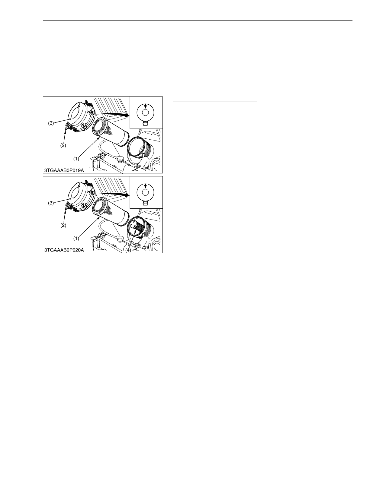
Cleaning Air Cleaner Element
[Single Element and Double Element Type]
1. Remove the air cleaner cover (3) and element (primary) (1).
2. Clean the element (primary) (1) if:
- When dry dust adheres to the element, blow compressed air
from the inside turning th e element. Pres sure of compr essed
air must be under 490 kPa (5 kgf/cm
- When ca rbon or oil adheres to the element, so ak the element
in detergent for 15 minutes then wash it several times in water,
rinse with clean water and dry it naturally. After element is fully
dried, inspect inside of the element with a light and check if it is
damaged or not.
3. When replacing the air cleaner element (primary) (1), replace the
secondary element (4) as well :
Once a year or after every six times of cleaning, whichever
comes first.
2
, 71 psi).
G GENERAL
W1017133
W1017188
• The air cleaner uses a dry element, never apply oil.
• Do not run the engine with filter element removed.
• Be sure to refit the du st cu p w ith th e ar row ↑ (on the rear of
cup) upright. If the dust cup i s improp erly fit ted, evacu ator
valve will not function and dust will adhere to the element.
• Do not touch the secondary element except in cases where
replacing is required.
■ Evacuator Valve
Open the evacuator valve (2) once a week under ordinary
conditions or daily when use d in a dusty place to get rid of large
particles of dust and dirt.
(1) Element (Primary)
(2) Evacuator Valve
(3) Cover
(4) Secondary Element (Safety)
W1017226
G-17
Page 32
STα-30 · STα-35, WSM
IMPORTANT■
IMPORTANT■
KiSC issued 11, 2006 A
G GENERAL
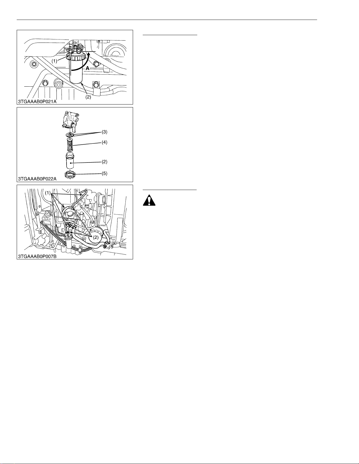
Cleaning Fuel Filter
This job should not be done in the field, but in a clean place.
1. Close the fuel filter cock (1).
2. Unscrew the sc rew ring and remove the fue l filter bowl (2), and
rinse the inside with kerosene.
3. Take out the filter element (4) and dip it in the kerosene to rinse.
4. After cleaning, reassemble the fuel filter, keeping out dust and
dirt.
5. Bleed the fuel system. (See page G-28.)
• If dust and dirt enters the fuel system the fuel pump and
injection nozzles are subject to premature wear. To prevent
this, be sure to clean the fuel filter bowl periodically.
(1) Fuel Cock
(2) Fuel Filter Bowl
(3) O-ring
(4) Filter Element
(5) Screw Ring
A : Close
W1017467
Checking Fuel Line
CAUTION
• Stop the engine when attempting the check and change
prescribed below.
• Remember to check t he fuel line periodically. The fuel line
is subject to wear and aging, fuel may leak out onto the
running engine, causing a fire.
1. Check to see that all line and hose clamps are tight and not
damaged.
2. If hoses and clamps are found worn or damaged, replace or
repair them at once.
3. The fuel l in e is made of rubber and a ges r eg ar dles s of peri od of
service. Replace the fuel pipe together with the clamp every two
years and securely tighten.
4. However if the fuel pipe and clamp are found damaged or
deteriorated earlier than two years, then change or remedy.
5. After the fuel line and clamp have been changed, ble ed the fuel
system. (See page G-28.)
• When the fuel line is disconnected for change, close both
ends of the fuel line with a piece of clean cloth or paper to
prevent dust and dirt from entering. Entrance of dust and
dirt causes malfunction of the fuel injection pump. In
addition, particular care must be take n not to admit dust and
dirt into the fuel pump.
(1) Fuel Hose (2) Clamp
W1017739
G-18
Page 33
STα-30 · STα-35, WSM
KiSC issued 11, 2006 A
G GENERAL
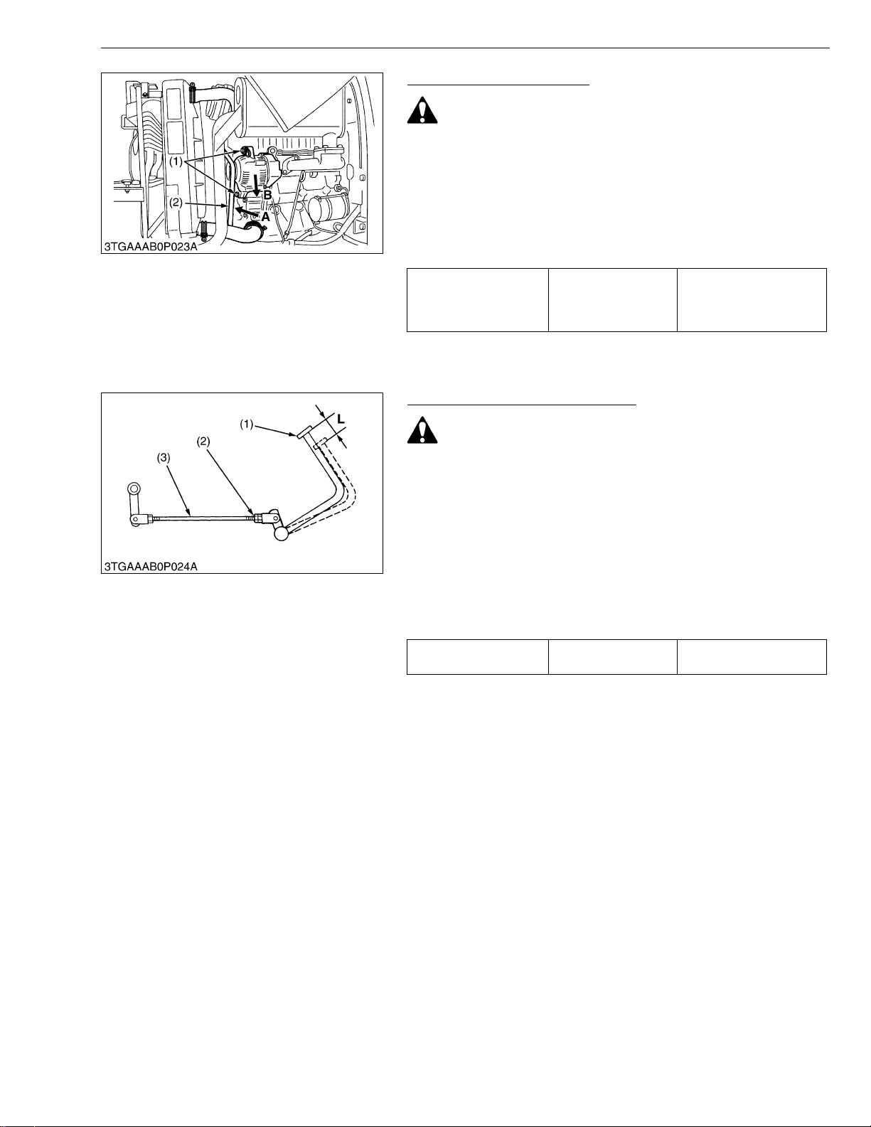
Checking Fan Belt Tension
CAUTION
• Be sure to stop engine before checking belt tension.
1. Stop the engine and remove the key.
2. Apply moderate thumb pressure to belt between pulleys.
3. If tension is incor rect, loosen the alternat or mounting bolts and
using a lever placed between the alternator and the engine block,
pull the alternator ou t until the deflection of the bel t falls within
acceptable limits.
4. Replace fan belt if it is damaged.
A deflection of between 7
Fan belt tension Factory spec.
to 9 mm (0.28 to 0.34 in.)
when the belt is pressed
in the middle of the span.
(1) Adjusting Screw
(2) Tension Bolt
A : Check the belt tension
B : To tighten
W1017926
Checking Brake Pedal Free Travel
CAUTION
• Stop the engine and chock the wheels before checking
brake pedal.
• The difference between the right and left pedal plays must
be less than 5.0 mm (0.19 in.).
1. Release the parking brake.
2. Slightly depress the brake pedals (1) and measure free travel (L)
at top of pedal stroke.
3. If the measurement is not within the factory specifications, loosen
the lock nut (2) and turn the brake rod (3).
4. Retighten the lock nut (2) securely.
Keep the free travel in the right and left brake pedals equal.
Brake pedal free travel
“L”
(1) Brake Pedal
(2) Lock Nut
(3) Brake Rod
Factory spec.
L : Free Travel
25 to 30 mm
0.98 to 1.18 in.
W1018154
G-19
Page 34
STα-30 · STα-35, WSM
IMPORTANT■
KiSC issued 11, 2006 A
G GENERAL
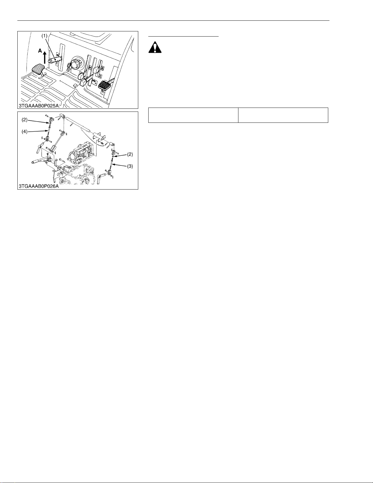
Checking Parking Brake
CAUTION
• Be sure to stop engine before checking parking brake.
1. Slowly raise the parking brake lever (1) to the ratchet sound
made by the parking brake lever.
2. If the No. of notch is not withi n the fac tory spec ificati ons, lo osen
the lock nut (2) and turn the brake rod LH (3) and RH (4) to adjust
within acceptable limits.
3. Retighten the lock nut (2) securely.
Parking brake lever free travel
2 notches
(Ratchet sound 2)
• Check the brake pedal free travel after checking the parking
brake.
(1) Brake Lever
(2) Lock Nut
(3) Brake Rod LH
(4) Brake Rod RH
A : Pull
W1018378
G-20
Page 35
STα-30 · STα-35, WSM
■
KiSC issued 11, 2006 A
G GENERAL
Checking Battery Condition
DANGER
To avoid the possibility of battery explosion:
For the refillable type battery, follow the instructions below.
• Do not use or charge the refillable type battery if the fluid level is
below the LOWER (lower limit level) mark.
Otherwise, the battery component parts may prematurely
deteriorate, which may shorten the battery’s service life or cause
an explosion. Che ck the fluid level regularly and ad d distilled
water as required so that the fluid level is b etween the UPPER
and LOWER levels.
CAUTION
• Never remove the vent plugs while the engine is running.
• Keep electrolyte away fr om eyes, h and s and clothe s. If you
are spattered with it, wash it away completely with water
immediately and get medical attention.
• Wear eye protection and rubber gloves when working
around battery.
1. Mishandling the battery shortens the service life and adds to
maintenance costs.
2. The original battery is maintenance free type battery, but need
some servicing.
If the battery is weak, the engine is difficult to start and the lights
become dim. It is important check the battery periodically.
NOTE
• The factory-installed battery is of non-refillable type. If the
indicator turns white, do not charge the battery but replace
it with new one.
■ How to read the indicator
Check the battery condition by reading the indicator.
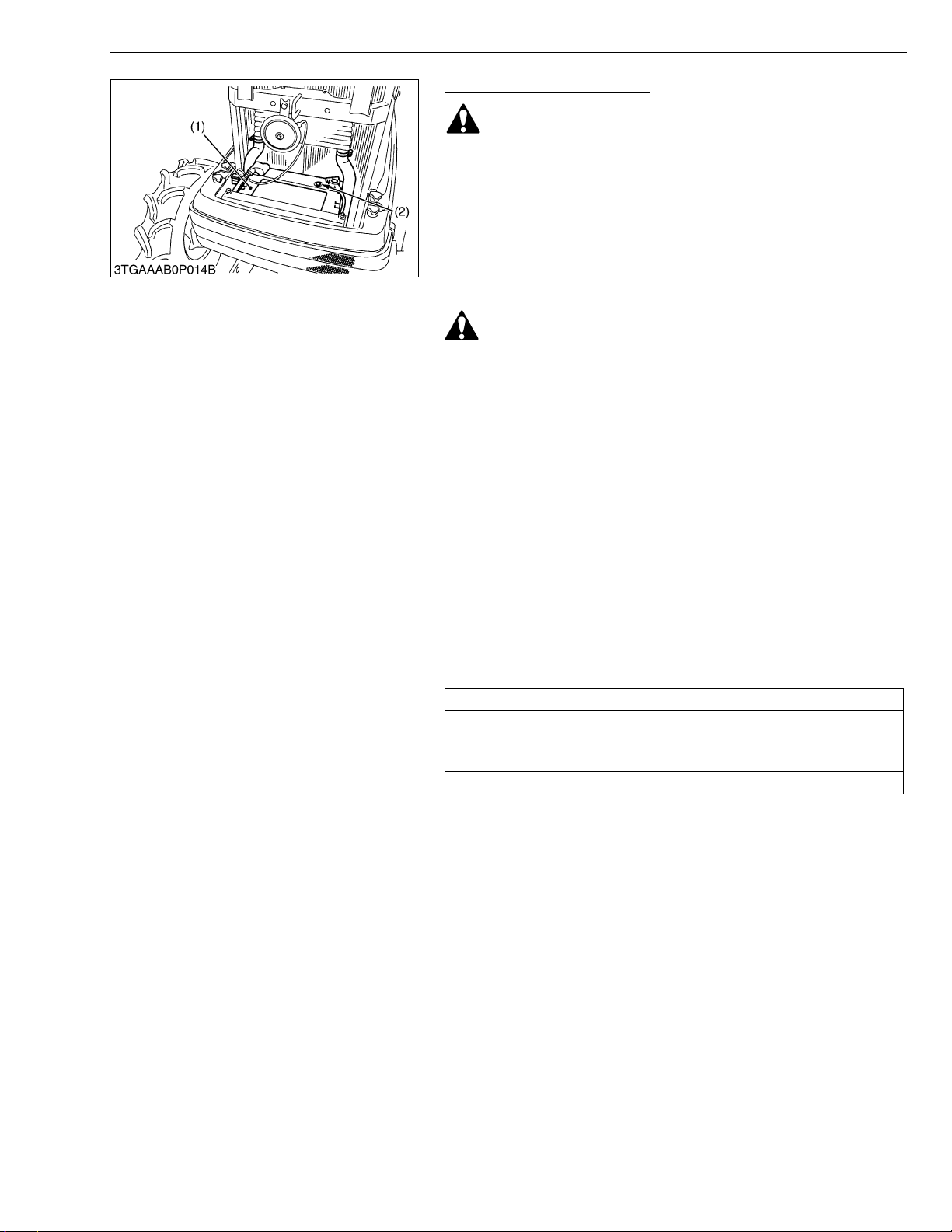
State of indicator display
Green
Black Needs charging battery.
White Needs changing battery.
Specific gravity of electrolyte and quality of electrolyte
are both in good condition.
(1) Battery (2) Indicator
W1018707
G-21
Page 36
STα-30 · STα-35, WSM
IMPORTANT■
KiSC issued 11, 2006 A
G GENERAL
■ Battery Charging
CAUTION
• When the battery is being activated, hydrogen and oxygen
gases in the battery are extremely explosive. Keep open
sparks and flames away from the battery at all times,
especially when charging the battery.
• When charging battery, remove battery vent plugs.
• When disconnecting the cable from the battery, start with
the negative terminal first.
When connecting the cable to the battery, start with the
positive terminal first.
• Never check battery charge by placing a metal object across
the posts.
Use a voltmeter or hydrometer.
1. To slow charge the battery, connect the battery positive terminal
to the charger positive terminal and the negative to the negative,
then recharge in the standard fashion.
2. The battery is charged if the indicator display turns green from
black.
• Do not charge rapidly.
3. When exchanging an old battery into new one, use battery of
equal specification shown in table 1.
Table 1
Capacity at
Battery Type Volts (V)
75D26L-MF 12 65 550 –
20 H.R.
(A.H.)
CCA (SAE)
Normal
Charging Rate
■ Direction for Storage
1. When storing the tractor for long periods of time, remove the
battery from tractor, adjust the electrolyte to the proper level and
store in a dry place out of direct sunlight.
2. The battery self-discharges while it is stored.
Recharge it once every three months in hot se asons and once
every six months in cold seasons.
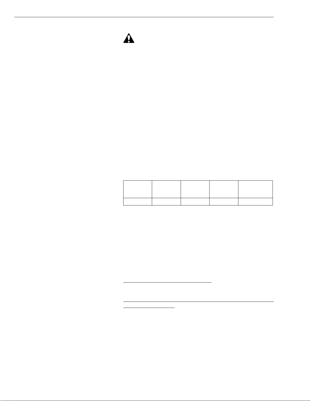
(1) Highest Level (2) Lowest Level
W1019057
[5] CHECK POINTS OF EVERY 200 HOURS
Replacing Engine Oil Filter Cartridge
1. See page G-12.
Replacing Hydraulic Oil Filter Cartridge and Transmission Oil
Filter (HST) Cartridge
1. See page G-13.
W1019450
W1019516
G-22
Page 37
STα-30 · STα-35, WSM
KiSC issued 11, 2006 A
G GENERAL
Checking Radiator Hose and Hose Clamp
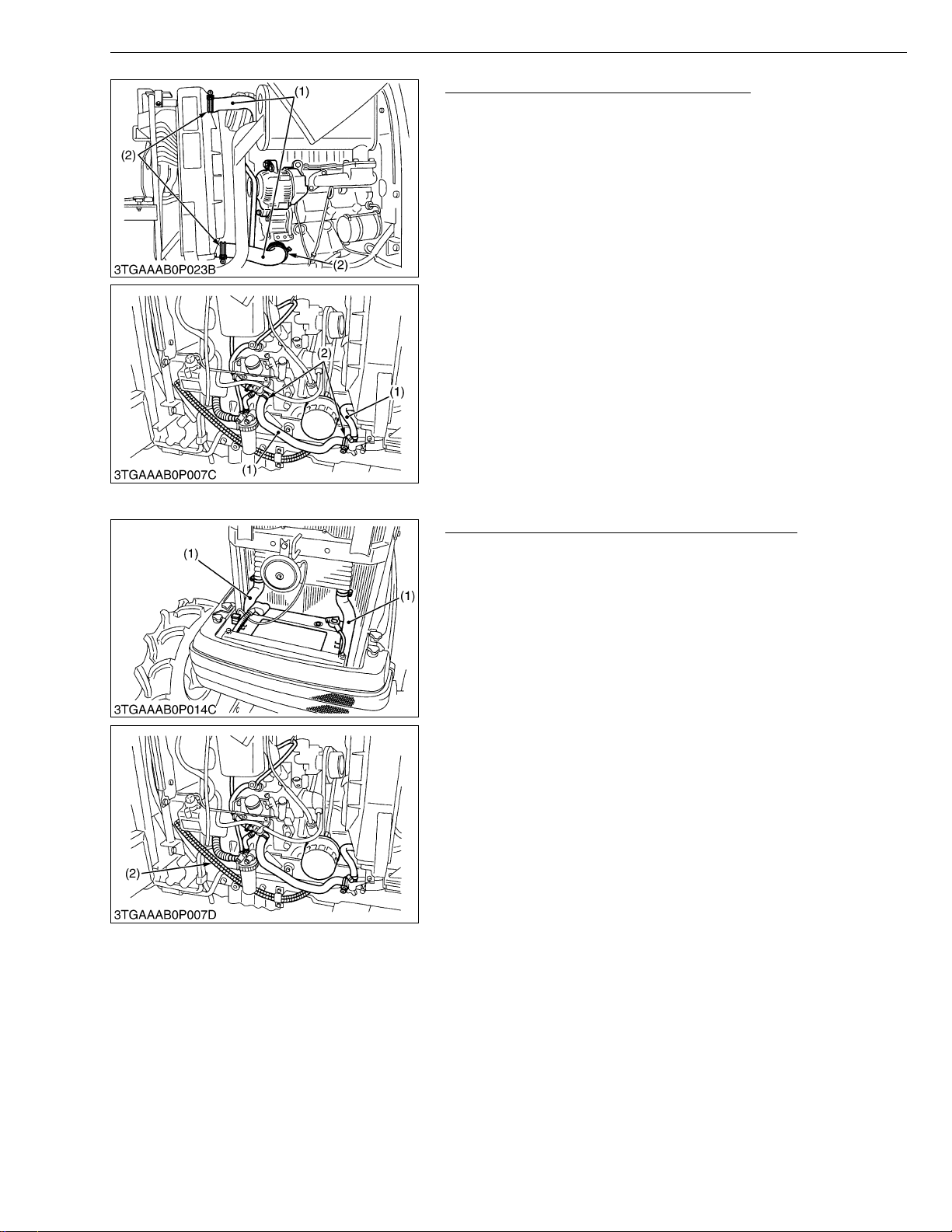
Check to see if radiator hoses are properly fixed every 200 hours
of operation or six months, whichever comes first.
1. If hose clamps are loose or water leaks, tighten bands securely.
2. Replace hoses and tighten hose clamps securely, if radiator
hoses are swollen, hardened or cracked.
Replace hoses and hose clamps every 2 years or earlier if
checked and found that hoses are swollen, hardened or cracked.
■ Precaution at Overheating
Take the following a ctions in the even t the coolant temper ature
be nearly or more than the boiling point, what is called
“Overheating”.
1. Stop the machine operati on in a sa fe pla ce and keep the engine
unloaded idling.
2. Don’t stop the engine suddenly, but stop it after about 5 minutes
of unloaded idling.
3. Keep yourself well away from the machine for further 10 minutes
or while the steam blown out.
4. Checking that ther e gets no dange r such as burn, get rid o f the
causes of overheating according to the manual, see
“Troubleshooting” section, and then, start again the engine.
(1) Radiator Hose (2) Clamp
W1019561
Checking HST Oil Line and Power Steering Line
1. Check to see that all lines (1), (2) and hose clamps are tight and
not damaged.
2. If hoses and clamps are found worn or damaged, replace or
repair them at once.
(1) HST Oil Line (2) Power Steering Hose
W1019910
G-23
Page 38
STα-30 · STα-35, WSM
IMPORTANT■
NOTE■
KiSC issued 11, 2006 A
G GENERAL
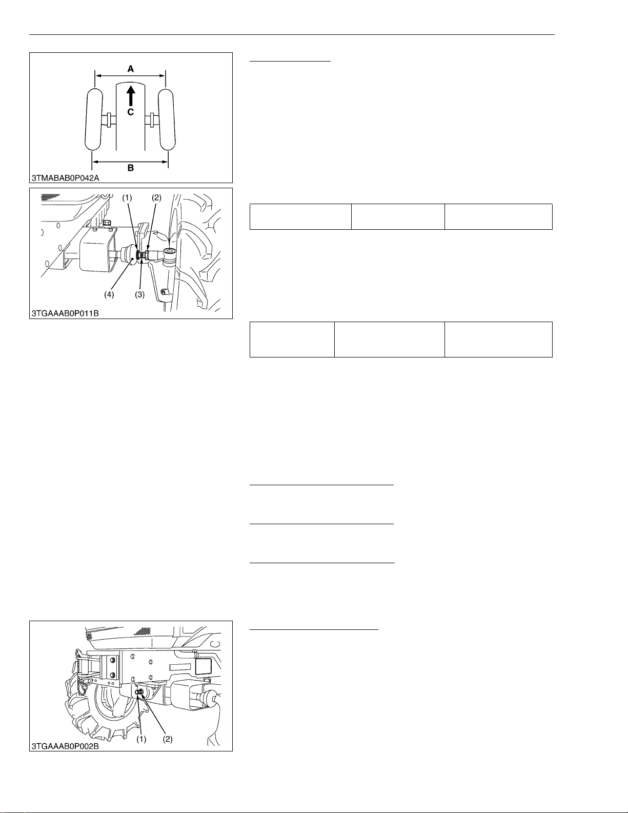
Adjusting Toe-in
1. Park the tractor on the flat place.
2. Inflate the tires to the specified pressure.
3. Turn steering wheel so front wheels are in the straight ahead
position.
4. Lower the implement, lock the parking brake and stop the engine.
5. Measure distance between tire beads at front of tire, hub height.
6. Measure distance between tire beads at rear of tire, hub height.
7. Front distance should be 2 to 8 mm (0.079 to 0.315 in.) less than
rear distance.
8. If the measurement is not within the factory specifications, adjust
by changing the tie-rod length .
Toe-in (B – A) Factory spec.
2 to 8 mm
0.079 to 0.315 in.
■ Adjusting
1. Detach the snap ring (1) from the dust cover (4).
2. Loosen the tie-rod lock nut (2) and turn the tie-rod joint (3) to
adjust the tie-rod l ength until the proper to e-in measurement is
obtained.
3. Retighten the tie-rod lock nut (2).
4. Attach the snap ring (1) to the dust cover (4).
117 to 137 N·m
Tightening torque Tie-rod lock nut
12 to 14 kgf·m
86.1 to 101.3 ft-lbs
• A right and left tie-rod joint is adjusted to the same length.
(1) Snap Ring
(2) Tie-rod Lock Nut
(3) Tie-rod Joint
(4) Dust Cover
[6] CHECK POINTS OF EVERY 400 HOURS
Changing Transmission Fluid
1. See page G-13.
Replacing Fuel Filter Element
1. See page G-18.
Changi ng Front Axle C a se Oil
1. See page G-14.
[7] CHECK POINTS OF EVERY 600 HOURS
Adjusting Front Axle Pivot
1. Loosen the lock nut (2), tighten the adjusti ng screw (1) all the
way, and then loosen the adjusting screw (1) by 1/6 turn.
2. Retighten the lock nut (2).
(A) Wheel to Wheel Distance at front
(B) Wheel to Wheel Distance at rear
(C) Front
W1020026
W1020659
W1020714
W1020752
• If the axle pivot pin adjustment is not correct, front wheel
vibration can occur causing vibration in the steering wheel.
(1) Adjusting Screw (2) Lock Nut
W1020797
G-24
Page 39

STα-30 · STα-35, WSM
KiSC issued 11, 2006 A
[8] CHECK POINTS OF EVERY 800 HOURS
Checking Valve Clearance
1. See page 1-S21.
[9] CHECK POINTS OF EVERY 1 YEAR
Replacing Air Cleaner Element (Primary) and Secondary
Element
1. See page G-17.
[10] CHECK POINTS OF EVERY 2 YEARS
Replacing Radiator Hose (Water Pipes)
1. Replace the hoses and clamps.
Refer to “Checking Radiator Hose and Hose Clamp”. (See
page G-23.)
Replacing Fuel Hose
1. Replace the fuel hoses and clamps, if necessary.
Refer to “Checking Fuel Line”. (See page G-18.)
Replacing Power Steering Hose
1. Replace the hoses and clamps.
Refer to “HST Oil Line and Power Steering Line”. (See page
G-23.)
Replacing HST Oil Line
1. Replace the hoses and clamps.
Refer to “HST Oil Line and Power Steering Line”. (See page
G-23.)
G GENERAL
W1021033
W1021125
W1021176
W1021231
W1021269
W1021597
G-25
Page 40
STα-30 · STα-35, WSM
■
KiSC issued 11, 2006 A
G GENERAL
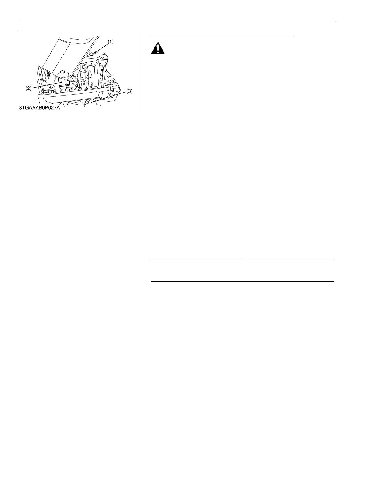
Flushing Cooling System and Changing Coolant
CAUTION
• Do not remove the radiator cap when the engine is hot. Then
loosen cap slightly to the stop to relieve any excess
pressure before removing cap completely.
1. Stop the engine and let cool down.
2. To drain the coolant, open the radiator drain plug (3) and remove
radiator cap (1). The radiator cap (1) must be removed to
completely drain the coolant.
3. After all coolant is drained, close the drain plug (3).
4. Fill with clean water and cooling system cleaner.
5. Follow directions of the cleaner instruction.
6. After flushing, fill with clean water and anti-freeze until the coolant
level is just below the port. Install the radiator cap (1) securely.
7. Fill with coolant up to “FULL” mark on the recovery tank (2).
8. Start and operate the engine for few minutes.
9. Stop the engine and let cool. Check coolant level of recovery tank
(2) and add coolant if necessary.
IMPORTANT
• Do not start engine without coolant.
• Use clean, fresh water and anti-freeze to fill the radiator and
recovery tank.
• When the anti-freeze is mixed with water, the anti-freeze
mixing ratio must be less than 50 %.
• Securely tighten radiator cap. If the cap is loose or
improperly fitted, water may leak out and the engine could
overheat.
• Refer to “LUBRICANTS, FUEL AND COOLANT”. (See page
G-8.)
Coolant capacity (with recovery tank)
5.8 L
1.56 U.S.qts.
1.28 Imp.qts.
(1) Radiator Cap
(2) Recovery Tank
(3) Drain Plug
W1021307
G-26
Page 41

STα-30 · STα-35, WSM
NOTE■
KiSC issued 11, 2006 A
G GENERAL
Flashing Cooling system and Changing Coolant (Continued)
■ Anti-Freeze
If coolant freezes, it can damage the cylinders and radiator. It is
necessary, if the ambi ent temperature falls below 0 °C (32 °F), to
remove coolant after operating or to add anti-freeze to it.
1. There are two types of anti- freeze availab le; use the perma nent
type (PT) for this engine.
2. Before adding anti-freeze for the first time, clean the radiator
interior by pouring fresh water and draining it a few times.
3. The procedure for mixing of water and anti-freeze differs
according to the make of the anti-freeze and the ambient
temperature, basically is should be referred to SAE J1034
standard, more specifically also to SAE J814c.
4. Mix the anti-freeze with water, and then fill in to the radiator.
Vol % Anti-freeze
40 −24 −12 106 222
50 −37 −34 108 226
Freezing Point Boiling Point*
°C °F °C °F
* At 760 mmHg pressure (atmospheric). A higher boiling point is
obtained by using a radiator pressure cap which permits the
development of pressure within the cooling system.
• The above date represent industry standards that
necessitate a minimum glyc ol content in the concentrated
anti-freeze.
• When the coolant level drops due to evaporation, add water
only. In case o f leakage, add anti-freeze and water in the
specified mixing ratio.
• Anti-freeze absorb s moist ure. Kee p un used a nti-f re ez e in a
tightly sealed container.
• Do not use radiator cleaning agents when anti-freeze has
been added to the coolant. (Anti-freeze contains an anticorrosive agent, which will react with the radiato r cleaning
agent forming sludge which will affect the engine parts.)
W1022492
G-27
Page 42
STα-30 · STα-35, WSM
IMPORTANT■
NOTE■
KiSC issued 11, 2006 A
[11] OTHERS
G GENERAL
Bleeding Fuel System
Air must removed:
1. When the fuel filter or lines are removed.
2. When tank is completely empty.
3. After the tractor has not been used for a long period of time.
Bleeding procedure is as follows:
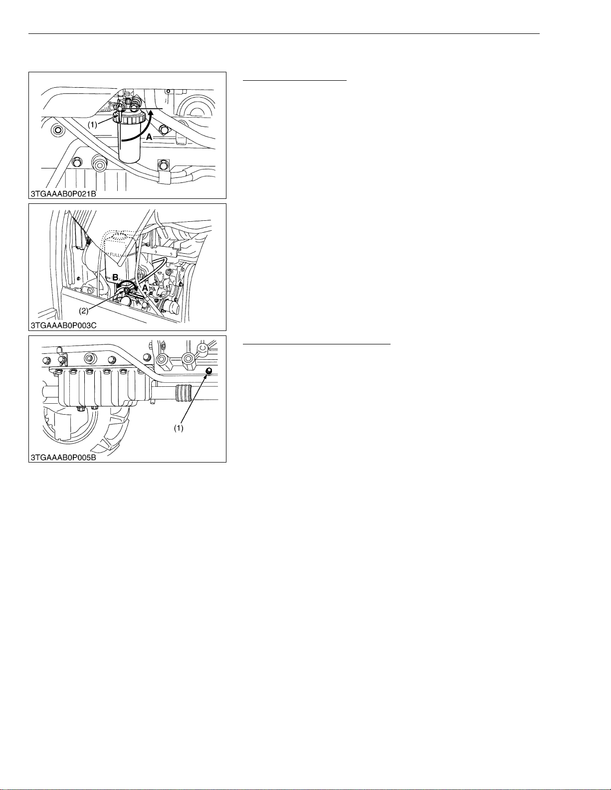
1. Fill the fuel tank with fuel, and open the fuel cock (1).
2. Open the air vent cock (2) on the fuel injection pump.
3. Start the engine and run for about 30 seconds, and then stop the
engine.
4. Close the air vent cock.
• Always close the air vent cock except for bleeding fuel lines.
Otherwise, engine runs irregularly or stalls frequently.
(1) Fuel Cock
(2) Air Vent Cock
A : Close
B : Open
W1022935
Draining Clutch Housing Water
• The tractor is equipped with drain plug (1) under the clutch
housing.
• After operating in rain, snow or tractor has been washed,
water may get into the clutch housing.
1. Remove the drain plug (1) and drain th e water, then install the
plug again.
(1) Water Drain Plug
W1023306
G-28
Page 43
STα-30 · STα-35, WSM
IMPORTANT■
KiSC issued 11, 2006 A
G GENERAL
Replacing Fuse
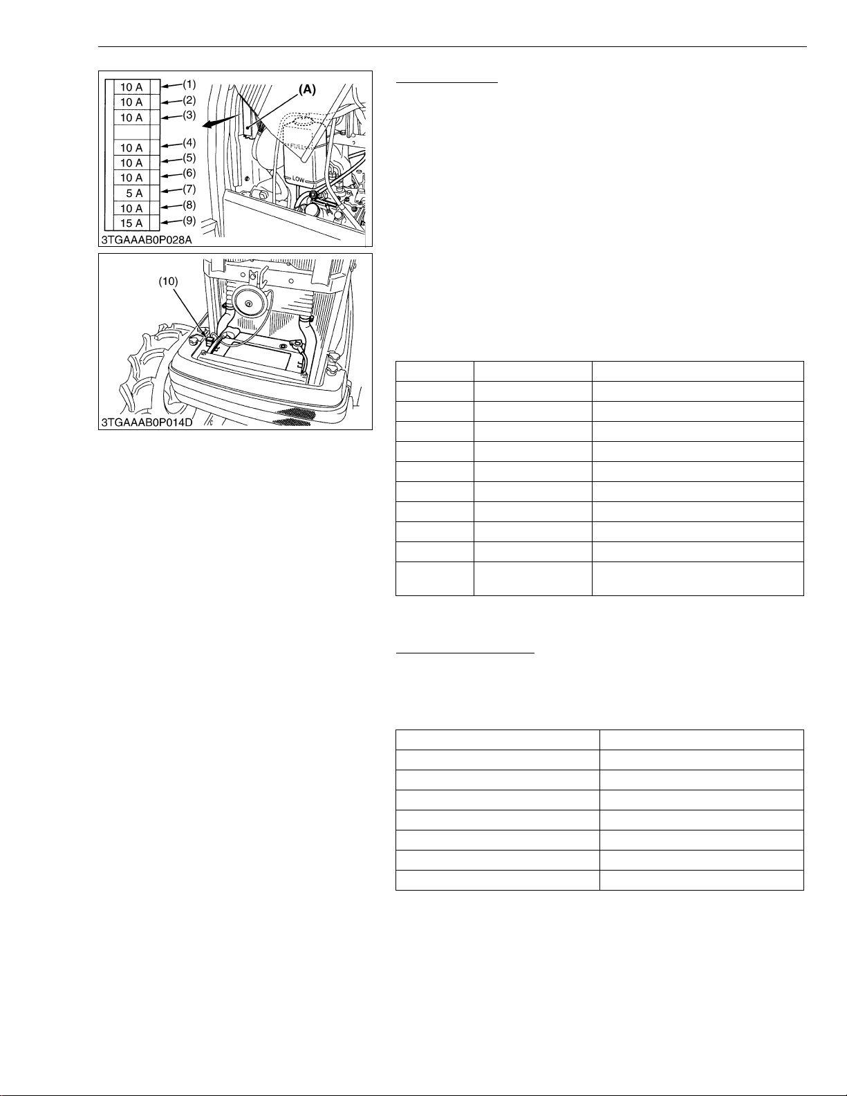
1. The tractor electric al syste m is prote cted from po tentia l dam age
by fuses.
A blown fuse indicates that there is an overload or short
somewhere in the electrical system.
2. If any of the fuses should blo w, replace with a new one of the
same capacity.
• Before replacing a blown fuse, determine why the fuse blew
and make any necessary repairs. Failure to follow this
procedure may result in serious damage to the tractor
electrical system. Refer to troubleshooting section of this
manual or your local KUBOTA distributor for specific
information dealing with electrical problems.
If any of them should blow, replace with a new one of the
same capacity.
■ Protected Circuit
Fuse No. Capacity (A) Protected circuit
1 10 Work light
2 10 Bi-speed
3 10 Brake light
4 10 Flasher lights
5 10 Hazard lights
6 10 Position lights
7 5 Panel instrument
8 10 Alternator, key stop
9 15 Head light, Horn
10 Slow blow fuse 50 A
Check circuit against wrong battery
connection
(A) Fuse Box
Replacing Light Bulb
1. Head lights and rear combination lights:
Take the bulb out of the light body and replace with a new one.
2. Other lights:
Detach the lens and replace the bulb.
Light Capacity
Head light 45 W / 40 W
Tail light 10 W
Brake stop light 21 W
Turn signal / Hazard light 21 W
Front position light 10 W
Instrument panel light 1.7 W
Number plate light 10 W
W1023430
W1023802
G-29
Page 44
STα-30 · STα-35, WSM
KiSC issued 11, 2006 A
9. SPECIAL TOOLS
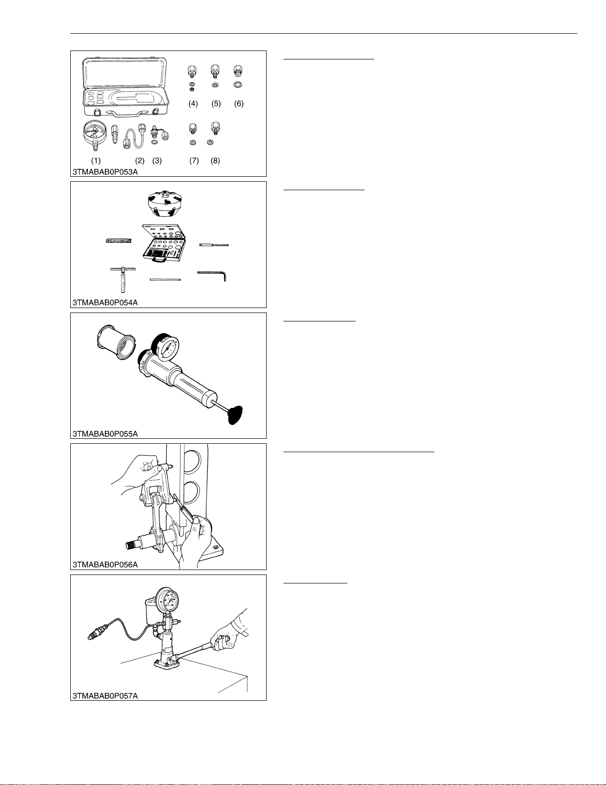
[1] SPECIAL TOOLS FOR ENGINE
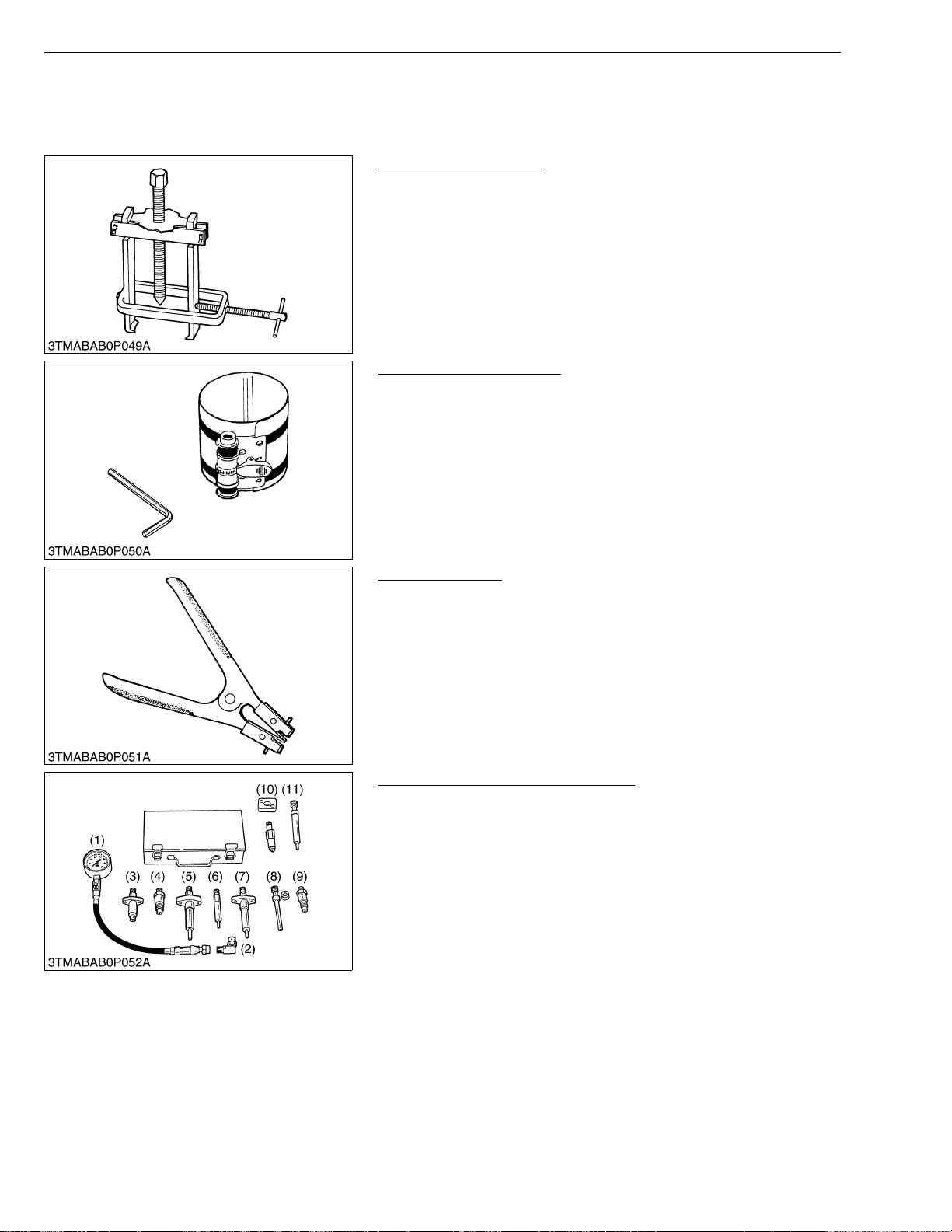
Special Use Puller Set
Code No: 07916-09032
Application: Use exclusively for pulling out bearing, gears and other
Piston Ring Compressor
Code No: 07909-32111
Application: Use exclusively for pushing in the piston with piston
G GENERAL
parts with ease.
W1024050
rings into the cylinder.
W1024100
Piston Ring Tool
Code No: 07909-32121
Application: Use exclusively for removing or installing the piston ring
with ease.
W1024150
Diesel Engine Compression Tester
Code No: 07909-30208 (Assembly) 07909-31251 (G)
07909-30934 (A to F) 07909-31271 (I)
07909-31211 (E and F) 07909-31281 (J)
07909-31231 (H)
Application: Use to measure diesel engine compression and
diagnostics of need for major overhaul.
(1) Gauge
(2) L Joint
(3) Adaptor A
(4) Adaptor B
(5) Adaptor C
(6) Adaptor E
(7) Adaptor F
(8) Adaptor G
(9) Adaptor H
(10) Adaptor I
(11) Adaptor J
W1024200
G-30
Page 45
STα-30 · STα-35, WSM
KiSC issued 11, 2006 A
G GENERAL
Oil Pressure Tester
Code No: 07916-32032
Application: Use to measure lubricating oil pressure.
(1) Gauge
(2) Cable
(3) Threaded Joint
(4) Adaptor 1
(5) Adaptor 2
(6) Adaptor 3
(7) Adaptor 4
(8) Adaptor 5
Valve Seat Cutter
Code No: 07909-33102
Application: Use to reseat valves.
Angle: 0.785 rad. (45°)
0.262 rad. (15°)
Diameter: 28.6 mm (1.126 in.) 38.0 mm (1.496 in.)
31.6 mm (1.244 in.) 41.3 mm (1.626 in.)
35.0 mm (1.378 in.) 50.8 mm (2.000 in.)
W1024318
W1024458
Radiator Tester
Code No: 07909-31551
Application: Use to check of radiator c ap pressu re, and leak s from
cooling system.
W1024532
Connecting Rod Alignment Tool
Code No: 07909-31661
Application: Use to check the connecting rod alignment.
Applicable: Connecting rod big end I.D.
range 30 to 75 mm (1.18 to 2.95 in.) dia.
Connecting rod length
65 to 300 mm (2.56 to 11.81 in.)
W1024583
Nozzle Tester
Code No: 07909-31361
Application: Use to check the fuel injection pressure and spray
pattern of nozzle.
Measuring: 0 to 50 MPa
2
range (0 to 500 kgf/cm
, 0 to 7000 psi)
W1024653
G-31
Page 46
STα-30 · STα-35, WSM
KiSC issued 11, 2006 A
G GENERAL
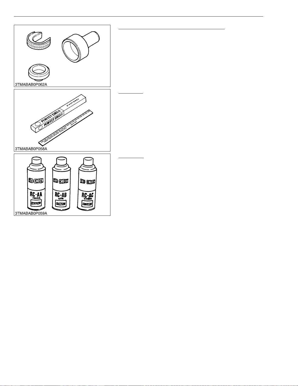
Auxiliary Socket For Fixing Crankshaft Sleeve
Code No: 07916-32091
Application: Use to fix the crankshaft sleeve of the diesel engine.
W1077114
Plastigage
Code No: 07909-30241
Application: Use to check the oil clearance between crankshaft and
bearing, etc.
Measuring: Green ....0.025 to 0.076 mm (0.001 to 0.003 in.)
range Red........0.051 to 0.152 mm (0.002 to 0.006 in.)
Blue.......0.102 to 0.229 mm (0.004 to 0.009 in.)
W1024719
Red Check
Code No: 07909-31371
Application: Use to check cracks on cyli nder head, cylinder bloc k,
etc.
W1024909
G-32
Page 47
STα-30 · STα-35, WSM
NOTE■
KiSC issued 11, 2006 A
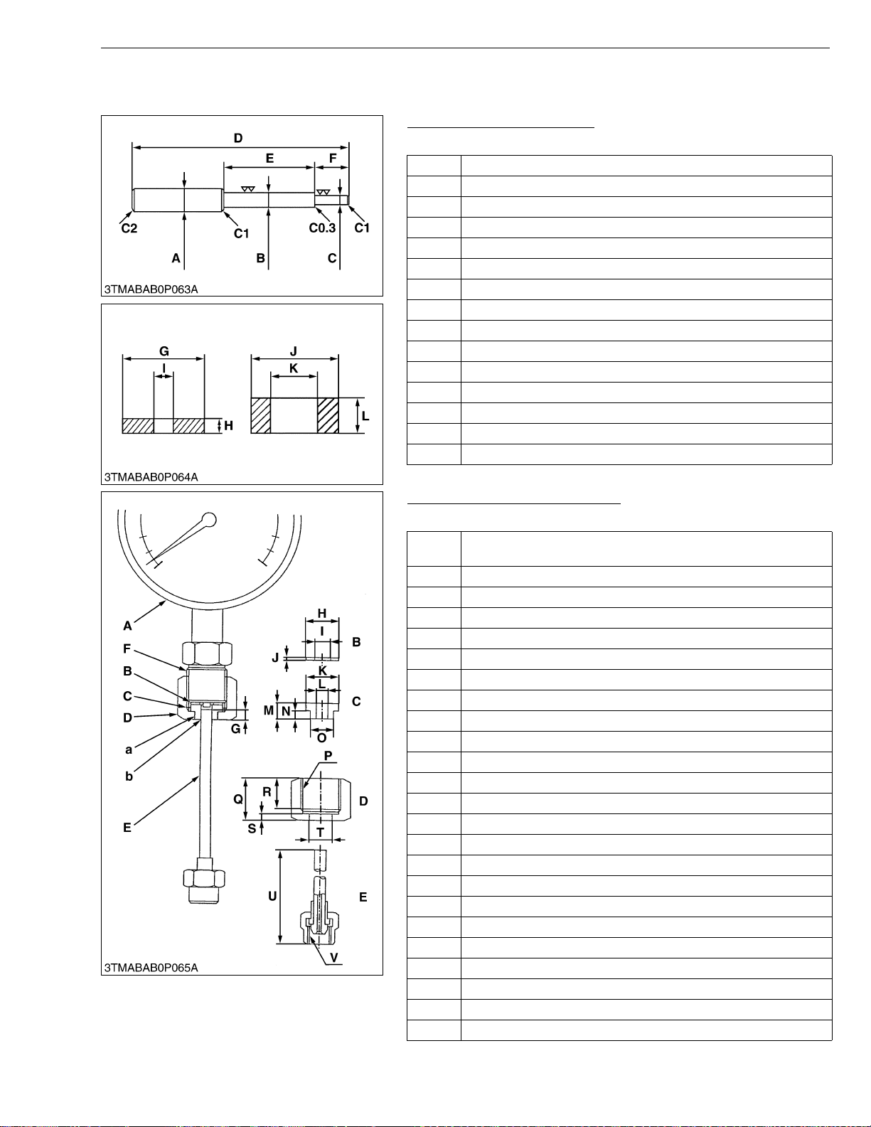
• The following special tools are not provided, so make them referring to the figure.
Valve Guide Replacing Tool
Application: Use to press out and press fit the valve guide.
A 20 mm dia. (0.79 in. dia.)
B 11.7 to 11.9 mm dia. (0.460 to 0.468 in. dia.)
C 6.5 to 6.6 mm dia. (0.256 to 0.259 in. dia.)
D 225 mm (8.86 in.)
E 70 mm (2.76 in.)
F 45 mm (1.77 in.)
G 25 mm (0.98 in.)
H 5 mm (0.197 in.)
I 6.7 to 7.0 mm dia. (0.263 to 0.275 in. dia.)
J 20 mm dia. (0.787 in. dia.)
K 12.5 to 12.8 mm dia. (0.492 to 0.504 in. dia.)
L 8.9 to 9.1 mm (0.350 to 358 in.)
C1 Chamfer 1.0 mm (0.039 in.)
C2 Chamfer 2.0 mm (0.079 in.)
C0.3 Chamfer 0.3 mm (0.012 in.)
Injection Pump Pressure Tester
Application: Use to check fuel tightness of injection pumps.
Pressure gauge full scale : More than 29.4 MPa (300 kgf/cm
A
psi)
B Copper gasket
C Flange (Material : Steel)
D Hex. nut 27 mm (1.06 in.) across the plat
E Injection pipe
FPF 1/2
G 5 mm (0.20 in.)
H 17 mm dia. (0.67 in. dia.)
I 8 mm dia. (0.31 in. dia.)
J 1.0 mm (0.039 in.)
K 17 mm dia. (0.67 in. dia.)
L 6.10 to 6.20 mm dia. (0.2402 to 0.2441 in. dia.)
M 8 mm (0.31 in.)
N 4 mm (0.16 in.)
O 11.97 to 11.99 mm dia. (0.4713 to 0.4721 in. dia.)
PPF 1/2
Q 23 mm (0.91 in.)
R 17 mm (0.67 in.)
S 4 mm (0.16 in.)
T 12.00 to 12.02 mm dia. (0.4724 to 0.4732 in. dia.)
U 100 mm (3.94 in.)
V M12 × P1.5
a Adhesive application
b Fillet welding on the enter circumference
G GENERAL
W1025017
2
, 4267
W1025240
G-33
Page 48
STα-30 · STα-35, WSM
KiSC issued 11, 2006 A
G GENERAL
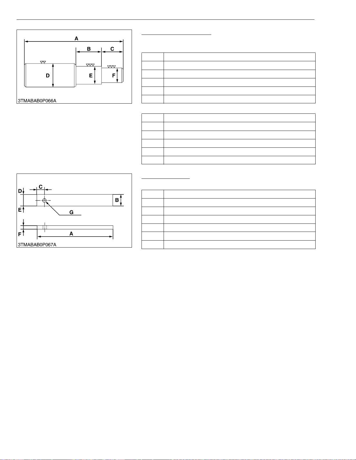
Bushing Replacing Tools
Application: Use to press out and to press fit the bushing.
(1) For small end bushing
A 162 mm (6.38 in.)
B 35 mm (1.38 in.)
C 27 mm (1.06 in.)
D 35 mm dia. (1.38 in. dia.)
E 27.90 to 27.95 mm dia. (1.098 to 1.100 in. dia.)
F 25.00 to 25.01 mm dia. (0.984 to 0.985 in. dia.)
(2) For idle gear bushing
A 175 mm (6.89 in.)
B 40 mm (1.57 in.)
C 38 mm (1.49 in.)
D 45 mm dia. (1.77 in. dia.)
E 41.90 to 41.95 mm dia. (1.650 to 1.652 in. dia.)
F 37.95 to 37.97 mm dia. (1.494 to 1.495 in. dia.)
W1025500
Flywheel Stopper
Application: Use to loosen and tighten the flywheel screw.
A 200 mm (7.87 in.)
B 30 mm (1.18 in.)
C 20 mm (0.79 in.)
D 15 mm (0.59 in.)
E 15 mm (0.59 in.)
F 8 mm (0 .3 1 i n .)
G 10 mm dia. (0.39 in. dia.)
W1025948
G-34
Page 49
STα-30 · STα-35, WSM
KiSC issued 11, 2006 A
G GENERAL
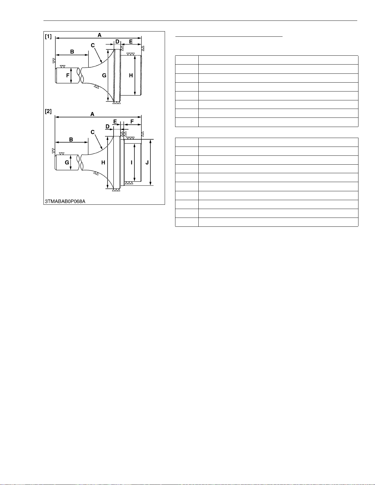
Crankshaft Bearing 1 Replacing Tool
Application: Use to press out and press fit the crankshaft bearing 1.
1. Extracting tool
A 135 mm (5.31 in.)
B 72 mm (2.83 in.)
C R40 mm (R1.57 in.)
D 10 mm (0.39 in.)
E 20 mm (0.79 in.)
F 20 mm dia. (0.79 in. dia.)
G 56.8 to 56.9 mm dia. (2.236 to 2.240 in. dia.)
H 51.8 to 51.9 mm dia. (2.039 to 2.043 in. dia.)
2. Inserting tool
A 130 mm (5.12 in.)
B 72 mm (2.83 in.)
C R40 mm (R1.57 in.)
D 9 mm (0.35 in.)
E 4 mm (0.16 in.)
F 20 mm (0.79 in.)
G 20 mm dia. (0.79 in. dia.)
H 68 mm dia. (2.68 in. dia.)
I 51.8 to 51.9 mm dia. (2.039 to 2.043 in. dia.)
J 56.8 to 56.9 mm dia. (2.236 to 2.240 in. dia.)
W1026139
G-35
Page 50
STα-30 · STα-35, WSM
KiSC issued 11, 2006 A
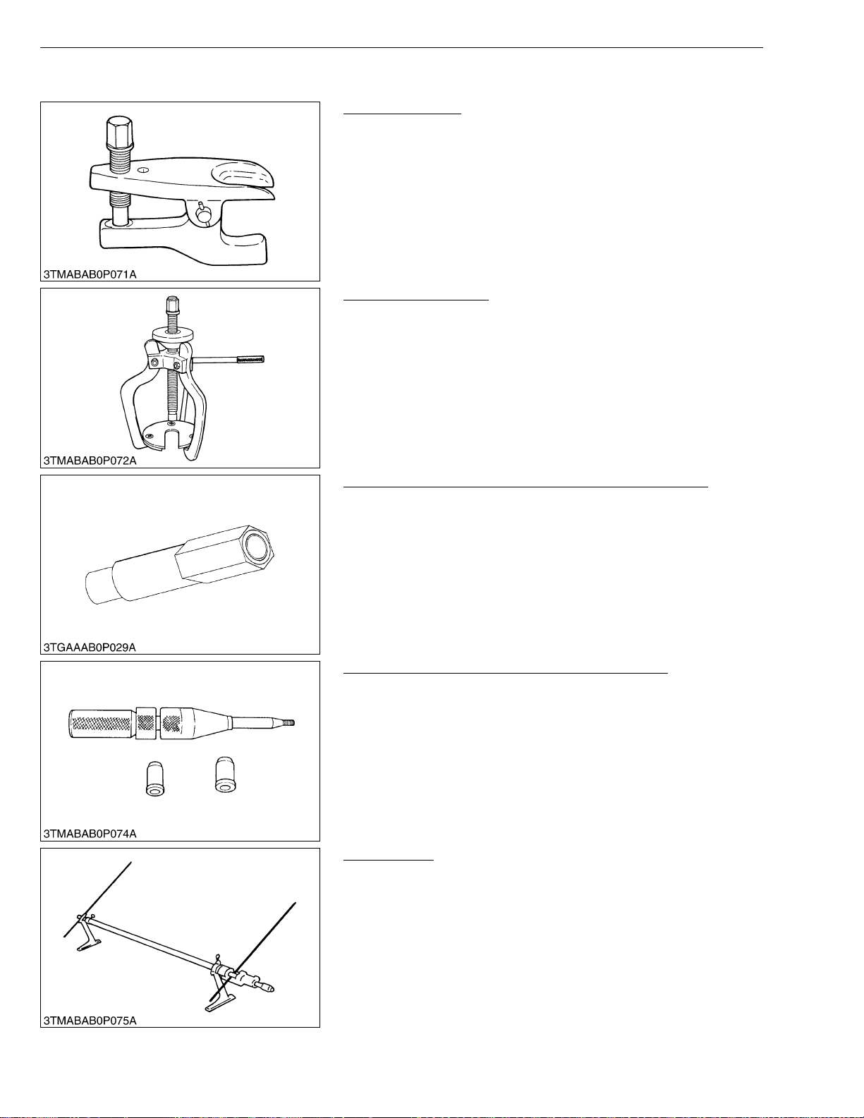
[2] SPECIAL TOOLS FOR TRACTOR
Tie-rod End Lifter
Code No: 07909-39051
Application: Use for removing the tie-rod end with ease.
Steering Wheel Puller
Code No: 07916-51090
Application: Use for removing the steering wheel without damaging
G GENERAL
W1026472
the steering shaft.
W1026533
Long Connector (HST Measurement Kit for B7100HST)
Code No: 07916-60831
Application: Use for checking HST charge relief pressure.
W1026585
Clutch Center Tool (For B and L Series Tractors)
Application: The clutch center tool can be used for all B and L series
tractors with a diaphragm clutch by changing tip guides.
Center piece diameter is 20 mm (0.79 in.).
W1026637
Toe-in Gauge
Code No: 07909-31681
Application: This allows easy measurement of toe-in for all machine
models.
W1026689
G-36
Page 51
STα-30 · STα-35, WSM
KiSC issued 11, 2006 A
G GENERAL
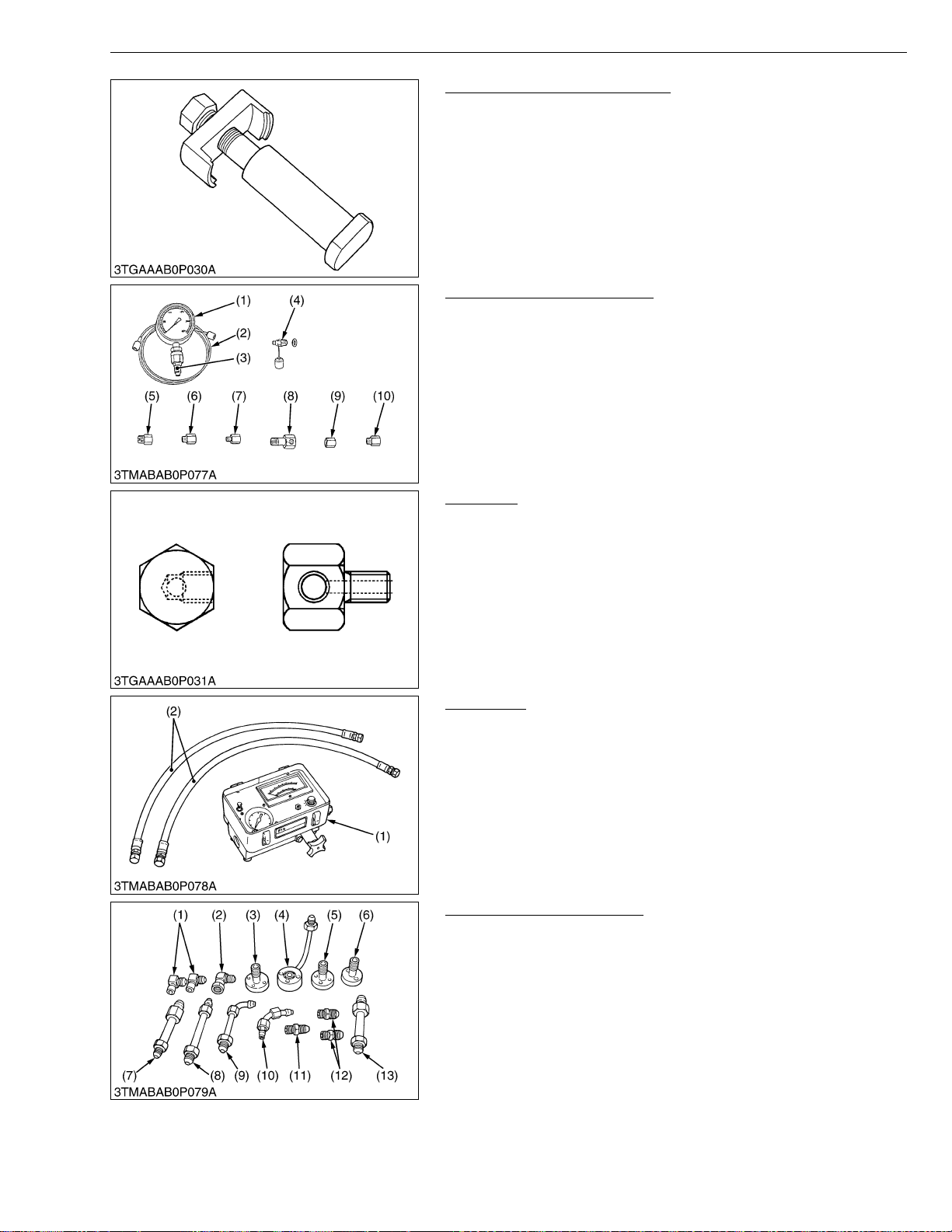
Clutch Pack Disassembly Tool
Code No: 07916-53741
Application: This allows easy installation of bi-speed clutch pack
spring.
W1073259
Relief Valve Pressure Tester
Code No: 07916-50045
Application: This allows easy measurement of relief set pressure.
(1) Gauge (07916-50322)
(2) Cable (07916-50331)
(3) Threaded Joint (07916-50401)
(4) Threaded Joint (07916-50341)
(5) Adaptor B (M18 × P1.5)
(07916-50361)
(6) Adap tor C (PS3/8) (07916-50371)
(7) Adap tor D (PT1/8) (07916-50381)
(8) Adap tor E (PS 3 /8) (07916-50392)
(9) Adap tor F (PF1/2) (07916-62601)
(10) Adaptor 58 (PT1/4) (07916-52391)
W1026741
Adaptor 7
Code No: 07916-32951
Application: Use for testing the hydraulic relief pressure.
Flow Meter
Code No: 07916-52791 (Flow Meter)
07916-52651 (Hydraulic Test Hose)
Application: This allows easy testing of hydraulic system.
(1) Flow Meter (2) Hydraulic Test Hose
Adaptor Set for Flow Meter
Code No: 07916-54031
Application: Use for testing the hydraulic system.
(1) Adaptor 52
(2) Adaptor 53
(3) Adaptor 54
(4) Adaptor 61
(5) Adaptor 62
(6) Adaptor 63
(7) Adaptor 64
(8) Adap tor 65
(9) Adap tor 66
(10) Adaptor 67
(11) Adaptor 68
(12) Adaptor 69
(13) Hydraulic Adaptor 1
W1077047
W1031318
W1031396
G-37
Page 52
STα-30 · STα-35, WSM
NOTE■
NOTE■
KiSC issued 11, 2006 A
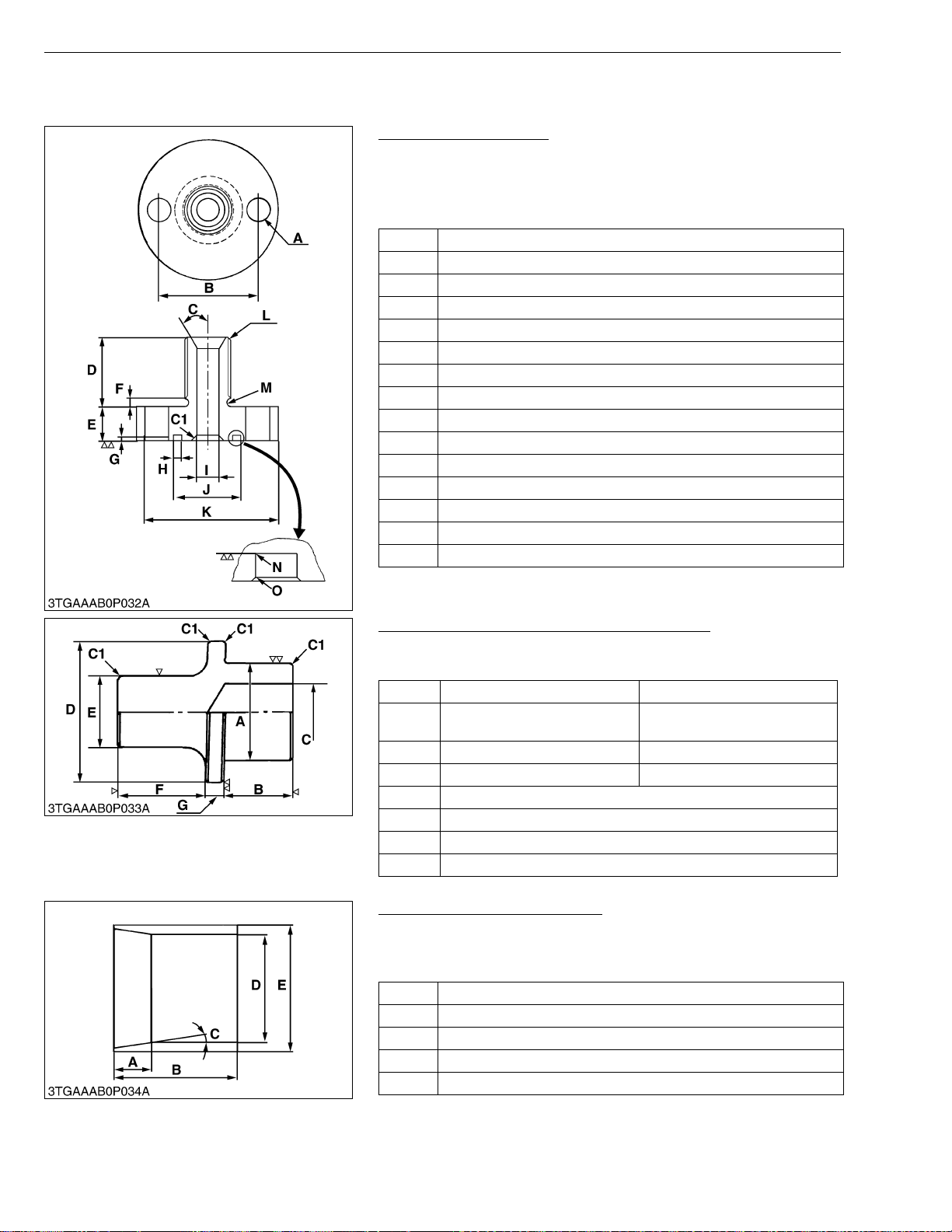
• The following special tools are not provided, so make them referring to the figure.
Adaptor for Flow Meter
Application: Use for checking the hydraulic pump for 3P linkage.
• When using, attach with following parts.
O-ring : 04811-00180
A 2-8.5 mm dia. (2-0.334 in.dia.)
B 40 mm (1.57 in.)
C 0.52 rad. (30 °)
D 25 mm (0.98 in.)
E 15 mm (0.59 in.)
F 3 mm (0.118 in.)
G 1.7 to 1.9 mm (0.067 to 0.075 in.)
H 3.0 to 3.25 mm (0.118 to 0.128 in.)
I 8.0 mm dia. (0.315 in. dia.)
J 23.9 to 24.1 mm dia. (0.941 to 0.945 in. dia.)
K 60 mm dia. (2.36 in. dia.)
L PS 3/8
M 1.5 mm Round (0.059 in. Round)
N 0.3 mm Round (0.012 in. Round)
O 0.2 mm Chamfer (0.0078 in. Chamfer)
G GENERAL
W1031593
Hydraulic Arm Shaft Bushing Replacing Tool
Applicatio n: Use for replacing the hy drau lic ar m sh aft bu shing in th e
hydraulic cylinder block.
Right Left
37.90 to 37.95 mm dia.
A
(1.492 to 1.494 in. dia.)
B 40 mm (1.575 in.) 35 mm (1.378 in.)
C 28 mm dia. (1.102 in. dia.) 25 mm dia. (0.984 in. dia.)
D 44.5 mm dia. (1.7 5 in. dia.)
E 30 mm dia. (1.18 in. dia.)
F 50 mm (1.97 in.)
G 10 mm (0.39 in.)
34.90 to 34.95 mm dia.
(1.374 to 1.376 in. dia.)
W1031655
Piston Gasket Correcting Tool
Application: Compress the power steering cyli nde r pist o n gask et to
the correct side when install the cylinder rod to the
cylinder tube with ease.
A 13.97 mm (0.55 in.)
B 35.052 mm (1.38 in.)
C 0.122 rad. (7 °)
D 40.000 to 40.039 mm dia. (1.57 to 1.58 in. dia.)
E 46 mm dia. (1.82 in. dia.)
W1073871
G-38
Page 53
STα-30 · STα-35, WSM
IMPORTANT■
IMPORTANT■
KiSC issued 11, 2006 A
G GENERAL
10.TIRES
[1] TIRE PRESSURE
CAUTION
• Do not attempt mount a tire. This should be down by a qualified person with the proper equipment.
• Always maintain the correct tire pressure.
Do not inflate tires above the recommended pressure as shown below.
• Do not use tires larger than specified.
• When you intend to mount different size of tires from equipped ones, consult your distributor about front
drive gear ratio for detail.
Excessive wear of tires may occur due to improper gear ratio.
Type Tire sizes Inflation pressure
Farm
Turf
6 – 12 4PR
Front
6.00 – 12 4PR
9.5 – 22 4PR
Rear
12.4 – 16 4PR
Front 24 × 8.50 – 14 4PR
Rear 13.6 – 16 4PR
200 kPa
2.0 kgf/cm
28.4 psi
180 kPa
1.8 kgf/cm
25.6 psi
140 kPa
1.4 kgf/cm
19.9 psi
120 kPa
1.2 kgf/cm
17.1 psi
160 kPa
1.6 kgf/cm
22.8 psi
96.5 kPa
1.0 kgf/cm
14 psi
2
2
2
2
2
2
Though the tire pressure is factory-set to the prescribed level, it naturally drops slowly in the course of time.
Thus, check it everyday and inflate as necessary.
[2] TREAD
CAUTION
• Support tractor securely on stands before removing a wheel.
• Never operate tractor with a loose rim, wheel or axle.
• Always attach tires as shown in the figure. (See page G-40.)
• If not attached as the figure, transmission parts may be damaged.
• Do not use tires larger than specified.
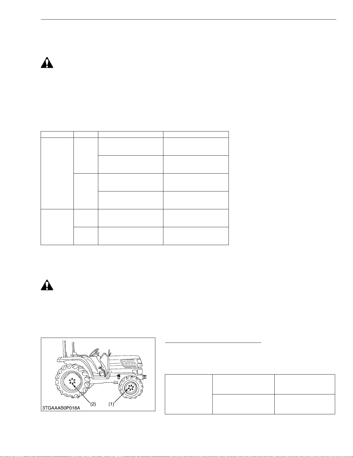
Wheel Tightening Screws and Nuts
1. When refittin g or adj ustin g a whe el, ti ghten t he sc rews an d nuts
with specified tightening torque.
2. Recheck after driving the tractor 200 m (200 yards) and therefore
according to service interval.
Front wheel mounting
screw and nut
Tightening torque
Rear wheel mounting
screw and nut
85 N·m
9.0 kgf·m
65.1 ft-lb s
215 N·m
22.0 kgf·m
159.1 ft-lbs
(1) Front Wheel (2) Rear Wheel
W1032716
G-39
Page 54
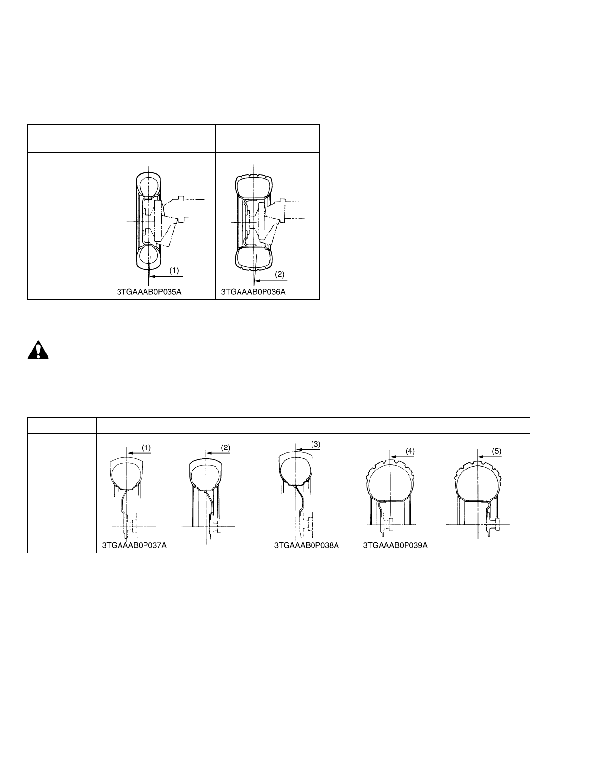
STα-30 · STα-35, WSM
IMPORTANT■
KiSC issued 11, 2006 A
G GENERAL
(1) Front Wheels
Front wheel tread cannot be adjusted.
• Do not turn front discs to obtain wider tread. In setting up the front wheels, make sure that the inflation
valve stem of the tires face outward.
Tires
6 – 12 Farm
6.00 – 12 Farm
24 × 8.50 – 14 Turf
Tread
(1) 1020 mm (40.16 in.) (2) 1 020 mm (40.16 in.)
(2) Rear Wheels
CAUTION
• When working on slopes or working with trailer, set the wheel tread as wide as practical for the job for
maximum stability.
Rear tread can be adjusted as shown with the standard equipped tires. To change the tread.
1. Change the position of the right and left tires.
Tires 9.5 – 22 Farm 12.4 – 16 Farm 13.6 – 16 Turf
Tread
(1) 950 mm (37.40 in.)
(2) 1070 mm (42.13 in.)
(3) 1148 mm (45.20 in.) (4) 965 mm (37.99 in.) (5) 1055 mm (41.5 in.)
G-40
Page 55
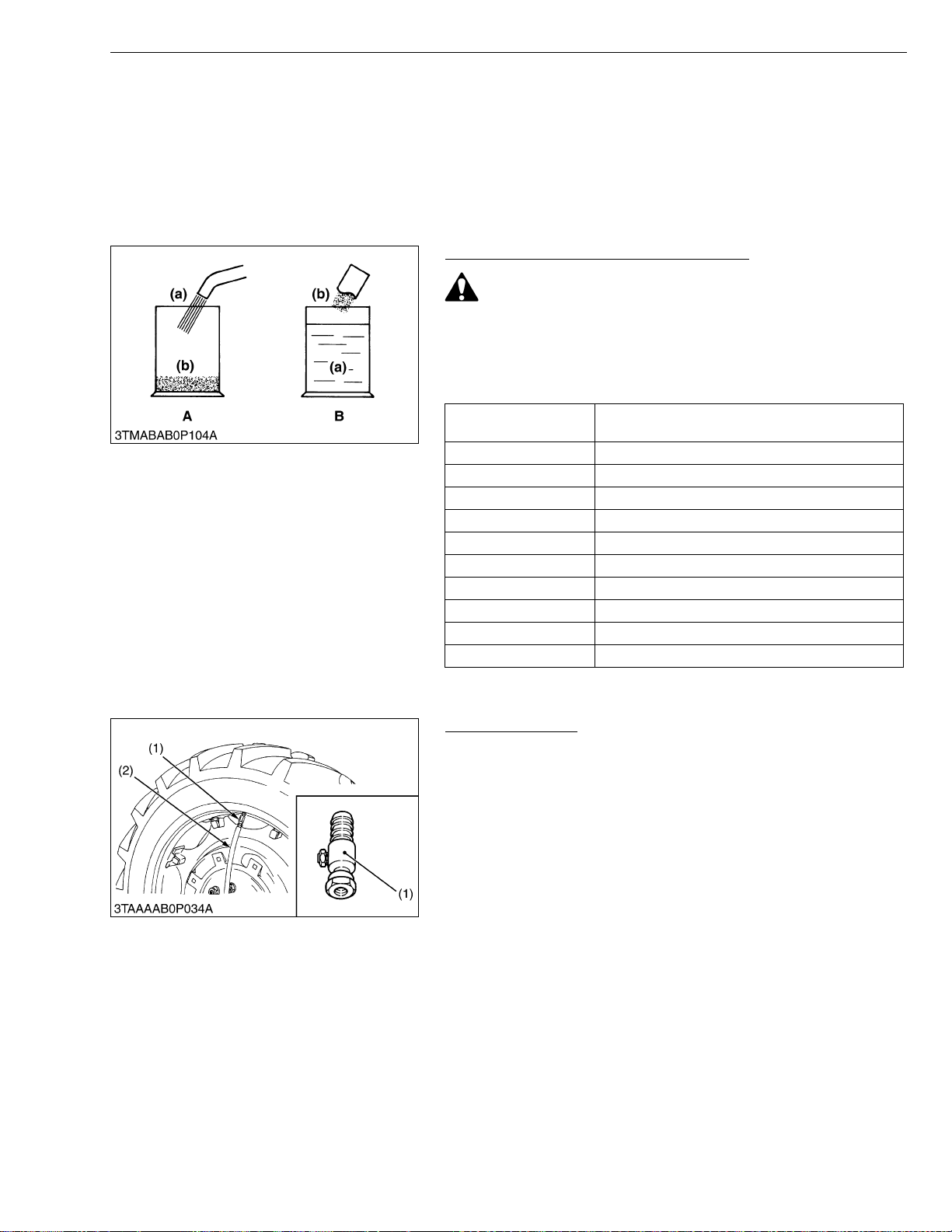
STα-30 · STα-35, WSM
IMPORTANT■
KiSC issued 11, 2006 A
G GENERAL
[3] TIRE LIQUID INJE CTION
Auxiliary weights can be used to increase traction force for plowing in fields or clayey ground.
Another way is to inject water or another liquid, such as a calcium chloride solution in the tires. Water must not be
used in winter s ince it freezes a t 0 °C (32 °F). The calcium c hloride solution w ill not freeze a nd moreover, af fords
higher effect than water since its specific gravity is higher than that of water by about 20 %. Below is an explanation
of calcium chloride solution injection.
• Do not fill the front tires with liquid.
Preparation of Calcium Chloride Solution
CAUTION
• When making a calcium chloride solution, do not pour water
over calcium chloride since this results in chemical reaction
which will cause high temperature. Instead add a small
amount of calcium chloride to the water at a time until the
desired solution is achieved.
Freezing temp.
−5 °C (23 °F) 12 kg (26.4 lbs)
−10 °C (14 °F) 21 kg (46.3 lbs)
−15 °C (5 °F) 28 kg (61.7 lbs)
−20 °C (−4 °F) 34 kg (75.0 lbs)
−25 °C (−13 °F) 40 kg (88.2 lbs)
−30 °C (−22 °F) 44 kg (97.0 lbs)
−35 °C (−31 °F) 49 kg (108 lbs)
−40 °C (−40 °F) 52 kg (114.6 lbs)
−45 °C (−49 °F) 56 kg (123.5 lbs)
−50 °C (−58 °F) 61 kg (134.5 lbs)
Weight of CaCl
(26.5 U.S.gals., 22.0 Imp.gals.) of water
2 to be dissolved in 100 L
(a) Water (b) CaCl
2 (Calcium Chloride)
W1033083
Attaching Injector
1. Lift the rear tires off the ground.
2. Turn the tire so that the air valve is at the top.
3. Remove the air valve, and attach the injector. (Code No. 07916-
52511)
(1) Injector (2) Hose
W1033331
G-41
Page 56
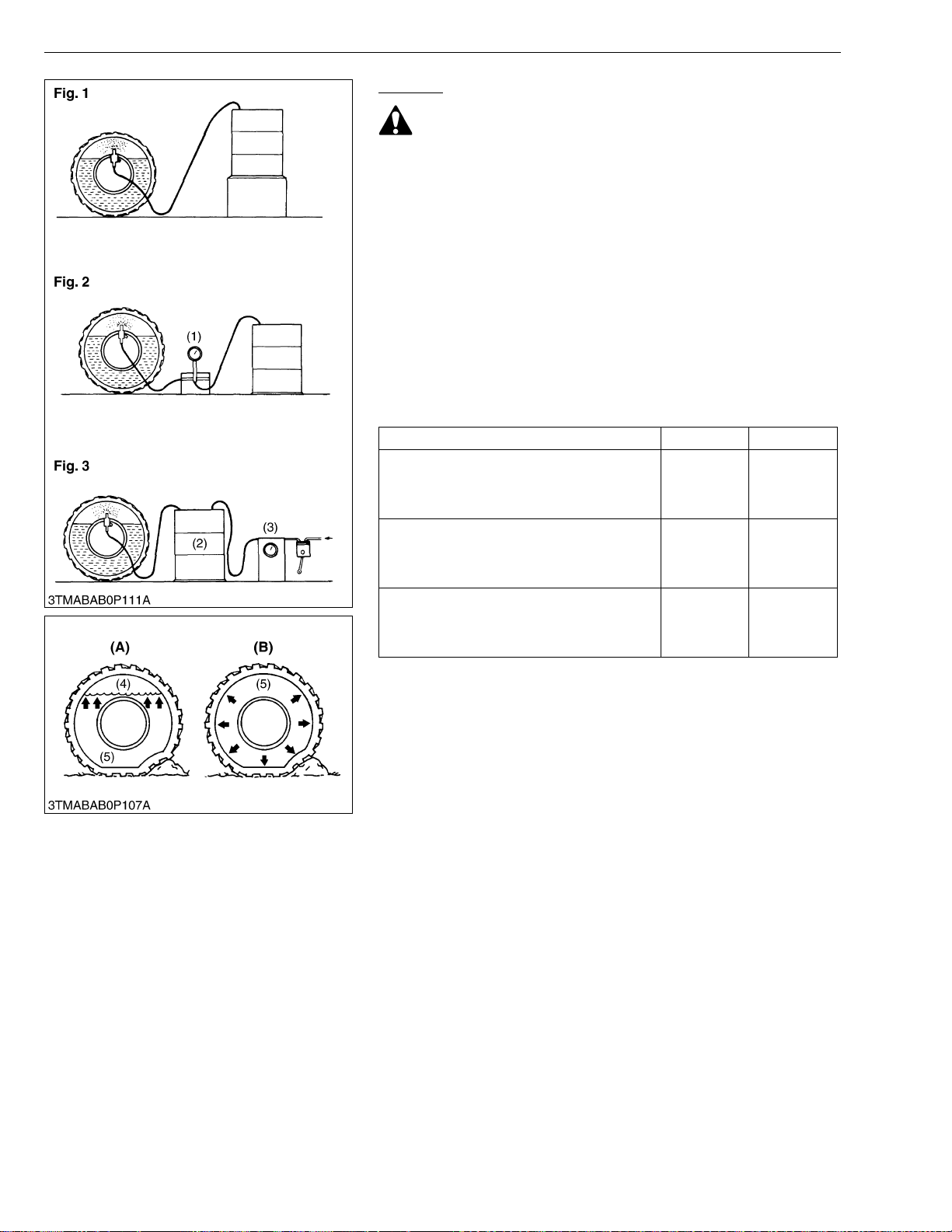
STα-30 · STα-35, WSM
■
KiSC issued 11, 2006 A
G GENERAL
Injection
CAUTION
• When a calcium chloride solution is used, cool it before
pouring it into the tire.
• Do not fill tires with water or solution more than 75 % of full
capacity (to the valve stem level).
The following four ways can be used to in jec t wate r or a calci um
chloride solution into tires.
1. Gravity injection (Fig. 1)
2. Pump injection (Fig. 2)
3. Pressure tank injection (Fig. 3)
4. Injection directly from tap (only when water is being use d).
NOTE
• Once injection is complete d, reset the air valve, and pump
air into the tire to the specified pressure.
Weight of Calcium Chloride Solution Filling 75 % of Full Capacity
of a Tire
Tire sizes 9.5-22 12.4-16
Slush free at −10 °C (14 °F)
Solid at −30 °C (−22 °F)
[Approx. 1 kg (2 lbs.) CaCl
water]
Slush free at −24 °C (−11 °F)
Solid at −47 °C (−53 °F)
[Approx. 1.5 kg (3.5 lbs.) CaCl
of water]
Slush free at −47 °C (−53 °F)
Solid at −52 °C (−62 °F)
[Approx. 2.25 kg (5 lbs.) CaCl
water]
2 per 4 L (1 gal.) of
2 per 4 L (1 gal.)
2 per 4 L (1 gal.) of
68 kg
(150 lbs)
72 kg
159 lbs
76 kg
(168 lbs)
85 kg
(187 lbs)
89 kg
(196 lbs)
94 kg
(207 lbs)
(1) Pump
(2) Pressure Tank
(3) Compressor
(4) Air
(5) Water
(A) Correct : 75 %
Air Compresses Like A Cushion
(B) Incorrect : 100 % Full
Water Can Not Be Compressed
W1033435
G-42
Page 57
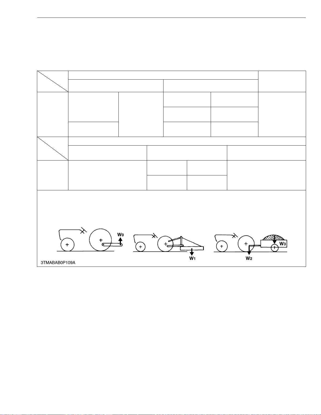
STα-30 · STα-35, WSM
NOTE■
KiSC issued 11, 2006 A
G GENERAL
11.IMPLEMENT LIMITATIONS
The KUBOTA Tractor has bee n thoroughly tested for proper performance with implemen ts sold or approved by
KUBOTA. Use with implements which exceed the maximum specifications listed below, or which are otherwise unfit
for use with the KUBOTA Tractor may result in malfunctions or failures of the tractor, damage to other prope rty and
injury to the operator or others. [Any malfunctions or failures of the tractor resulting from use with improper implements
are not covered by the warranty.]
Max. width of tire tread Lower link end
Front Rear
1070 mm
(421.26 in.)
1148 mm
(451.97 in.)
1055 mm
(415.35 in.)
STα-30
STα-35
6 – 12 Farm
9.5-22 Farm
6.00 – 12 Farm
1020 mm
(401.57 in.)
12.4-16 Farm
(Option)
24 × 8.50 – 14 Turf 13.6-16 Turf
Actual figures
Lift capacity 24 inches behind
lower link end W
STα-30
STα-35
0 :Lower link end max. hydraulic lifting capacity
W
1 :The implement’s weight which can be put on the lower link (Implement weight)
W
2 :Max. drawbar load
W
3 :The max. loading weight for trailer (without trailer’s weight) (Trailer loading weight)
W
890 kg (1962 lbs)
1
Max. Drawbar Load W2
Drawber
High-hitch
500 kg
(1102 lbs)
490.5 kg
(1081 lbs)
Trailer loading weight W3
Max. capacity
1500 kg (3300 lbs)
max. lifting
capacity W
1150 kg
(2535 lbs)
0
• Implement size may vary depending on soil operating conditions.
G-43
Page 58

1 ENGINE
KiSC issued 11, 2006 A
Page 59

MECHANISM
KiSC issued 11, 2006 A
CONTENTS
1. FUEL SYSTEM ............................................................................................. 1-M1
[1] GOVERNOR ............................................................................................1-M1
NOTICE
For not above-mentioned engine mechanism information, please refer ENGINE MECHANISM
WSM (97897-01871).
Page 60
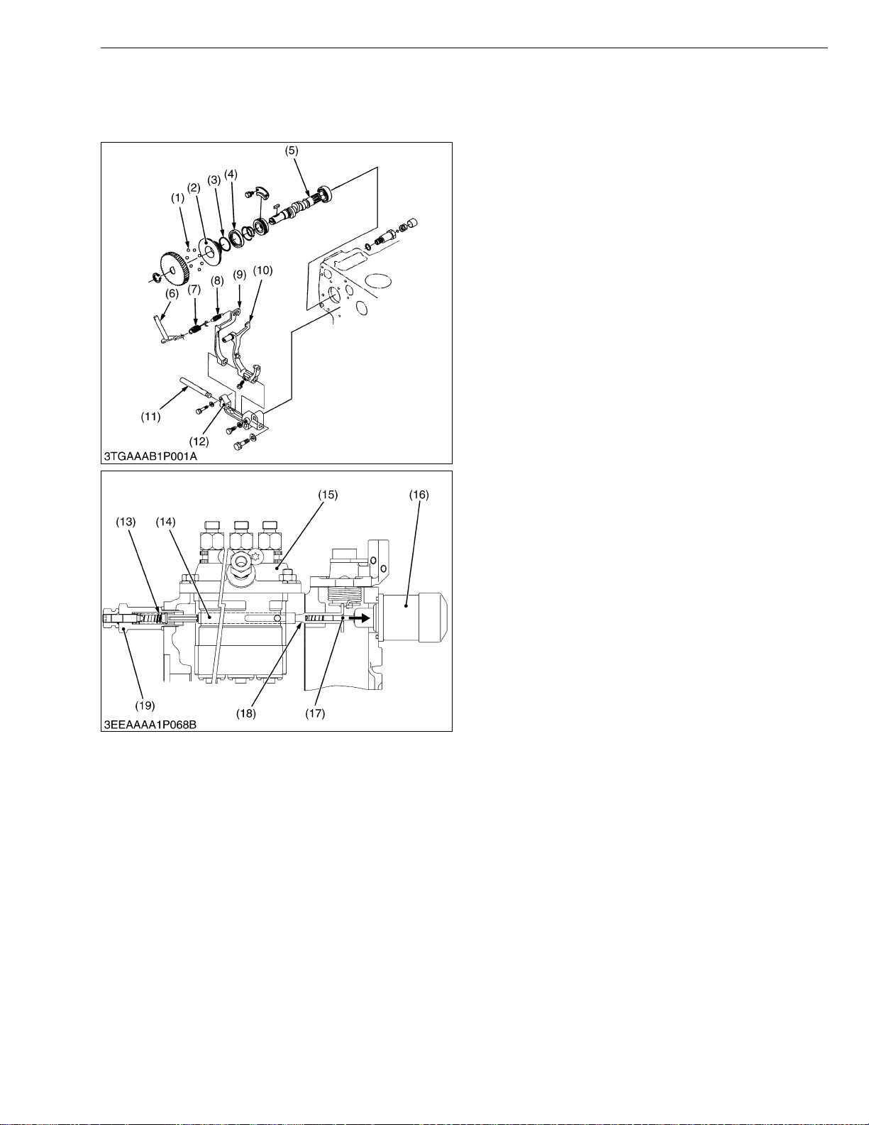
STα-30 · STα-35, WSM
KiSC issued 11, 2006 A
1. FUEL SYSTEM
[1] GOVERNOR
ENGINE
The governor serves to keep engine speed cons tant
by automatically adjusting the amount of fuel supplied to
the engine according to changes in the load. This engine
employs an all-speed governor which controls the
centrifugal force of the steel ball (1) weight, produced by
rotation of the fuel camshaf t (5), and the tension of the
governor spring 1 (7) and 2 (8) are balanced.
(1) Steel Ball
(2) Governor Sleeve
(3) Steel Ball
(4) Governor Ball Case
(5) Fuel Camshaft
(6) Governor Lever
(7) Gov ernor Spring 1
(8) Gov ernor Spring 2
(9) Fork Lever 2
(10) Fork Lever 1
(11) Fork Lever Shaft
(12) Fork Lever Holder
W1017186
■ At Start
Flowing of the battery current into the engine stop
solenoid (16), the plunger (17) is actuated to arrow
direction.
Since the steel ball (1) have no cen trifugal for ce, the
control rack (14) is pushed to the right by the start spring
(13). Accordingly, the control rack (14) moves to the
maximum injection position to assure easy starting.
(13) Start Spring
(14) Control Rack
(15) Injection Pump
(16) Engine Stop Solenoid
(17) Plunger
(18) Guide
(19) Idling Apparatus
W1017215
1-M1
Page 61
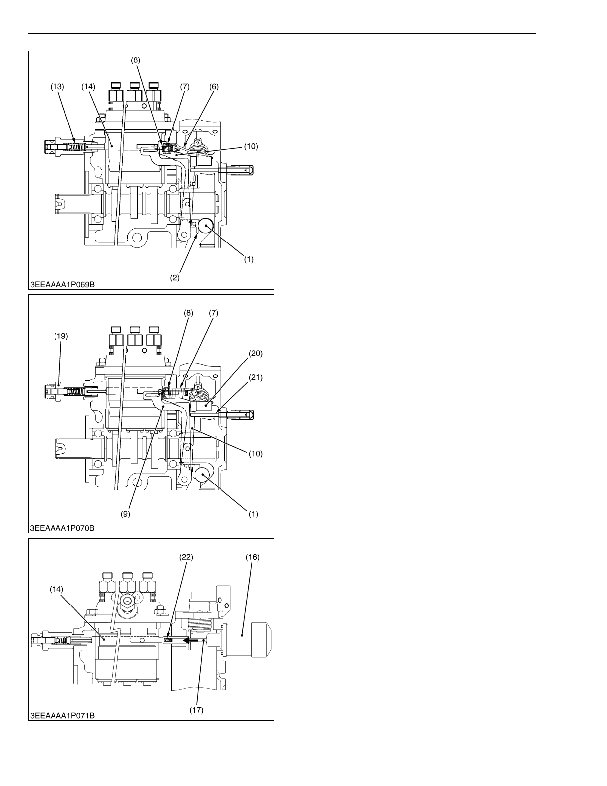
STα-30 · STα-35, WSM
KiSC issued 11, 2006 A
ENGINE
■ At Idling
When the speed control lever is set at the idling
position after the engine starts, the governor spring 1 (7)
does not work at all and the governor spring 2 (8) does
only act slightly. The governor sleeve (2) is pushed
leftward by a centrifugal force of steel ball (1).
Therefore, the fork lever 1 (10) and control rac k (14)
are moved to the left by the governor sleeve (2) and then
the start spring ( 13) is compres sed by the control rack.
As a result, the control rack is kept at a position where a
centrifugal force of st eel ball and forces of start spring
(13), governor spring 2 (8) are balanced, providing stable
idling.
(1) Steel Ball
(2) Governor Sleeve
(6) Governor Lever
(7) Governor Spring 1
(8) Governor Spring 2
(10) Fork Lever 1
(13) Start Spring
(14) Control Rack
W1017317
■ At High Speed Running with Overload
When an overload is applied to the engine running at
a high speed, the centrifugal force of steel ball (1)
becomes small as the engine speed is dropped, and fork
lever 2 (9) is pulled to the right by the governor springs 1
(7) and 2 (8), increasing fuel injection. Though, fork lever
2 (9) becomes ineffective in increasing fuel injection
when it is stopped by the adjusting screw (21).
After that, when the force of torque spring (20)
becomes greater than the ce ntrifugal force of the steel
ball, fork lever 1 (10) moves rightward to in crease fuel
injection, causing the engine to run continuously at a high
torque.
(1) Steel Ball
(7) Governor Spring 1
(8) Governor Spring 2
(9) Fork Lever 2
(10)Fork Lever 1
(19) Idling Apparatus
(20) Torque Spring
(21) Adjusting Screw
W1017384
■ To Stop Engine
When the battery current stops, the plu nger (17) of
engine stop solenoid (16) is returned to the original
position, the spring (22) to keep the control rack (14) in
“No fuel injection” position.
(14) C ontrol Rack
(16) Engine Stop Solenoid
(17) Plunger
(22) Spring
1-M2
W1018007
Page 62

SERVICING
KiSC issued 11, 2006 A
CONTENTS
1. TROUBLESHOOTING....................................................................................1-S1
2. SERVICING SPECIFICATIONS ....................................................................1-S4
3. TIGHTENING TORQUES ............................. ....... ...... ....... ...... ....... ...... ....... .1-S10
4. CHECKING, DISASSEMBLING AND SERVICING....................................1-S11
[1] SEPARATING ENGINE FROM TRACTOR .........................................1-S11
[2] ENGINE BODY ......................................................................................1-S20
(1) Checking and Adjusting ............................ ...... ....... ...........................1-S20
(2) Disassembling and Assembling........................................................1-S22
(3) Servicing ...........................................................................................1-S32
[3] LUBRICATING SYSTEM ............................... ...... ....... ...... ....... ...... ....... .1-S48
(1) Checking...........................................................................................1-S48
(2) Servicing ...........................................................................................1-S48
[4] COOLING SYSTEM...............................................................................1-S49
(1) Checking and Adjusting ............................ ...... ....... ...........................1-S49
[5] FUEL SYSTEM ....................................... ....... ....................................... .1-S51
(1) Checking and Adjusting ............................ ...... ....... ...........................1-S51
(2) Disassembling and Assembling........................................................1-S54
Page 63

STα-30 · STα-35, WSM
KiSC issued 11, 2006 A
1. TROUBLESHOOTING
ENGINE
Symptom Probable Cause Solution
Engine Does Not
Start
Starter Does Not Run • Battery discharged
Engine Revolution is
Not Smooth
Either White or Blue
Exhaust Gas is
Observe
• No fuel
• Air in the fuel system
• Water in the fuel system
• Fuel pipe clogged
• Fuel filter clogged
• Excessively high viscosity of fuel or engine oil
at low temperature
• Fuel with low cetane number
• Fuel leak due to l oos e inj ect ion pip e ret a ini ng
nut
• Incorrect injec tio n timi ng
• Fuel camshaft worn
• Injection nozzle clogged
• Injection pump malfunctioning
• Seizure of crankshaft, camshaft, piston,
cylinder or bearing
• Compression leak from cylinder
• Improper valve timing
• Piston ring and cylinder worn
• Excessive valve clearance
• Starter malfunctioning
• Main switch malfunctioning
• Clutch safety switch, HST safety switch or
PTO safety switch improperly adjusted or
defective
• Starter relay defective
• Wiring disconnected
• Fuel filter clogged or dirty
• Air cleaner clogged
• Fuel leak due to l oos e inj ect ion pip e ret a ini ng
nut
• Injection pump malfunctioning
• Incorrect nozzle injection pressure
• Injection nozzle stuck or clogged
• Governor malfunctioning
• Excessive engine oil
• Piston ring and cylinder worn or stuck
• Incorrect injec tio n timi ng
• Deficient compr es s ion
Replenish fuel
Bleed
Change fuel and
repair or replace fuel
system
Clean
Change
Use the spec ified fu el
or engine oil
Use the specified fuel
Tighten nut
Adjust
Replace
Clean
Repair or replace
Repair or replace
Replace head
gasket, tighten
cylinder head screw,
glow plug and nozzle
holder
Correct or replace
timing gear
Replace
Adjust
Charge
Repair or replace
Repair or replace
Repair or replace
Replace
Connect
Change
Clean or change
Tighten nut
Repair or replace
Adjust
Repair or replace
Repair
Reduce to the
specified level
Repair or replace
Adjust
Adjust top clearance
Reference
Page
G-8
G-28
–
–
G-18
G-8
G-8
–
1-S50
–
–
–
–
1-S20
–
1-S40, S47
1-S21
G-22
10-S8
10-S7
2-S4, 3-S7,
10-S10
10-S8
–
G-18
G-17
–
–
1-S53
1-S54
1-S24
G-12
1-S40, S47
1-S51
1-S22
W1014322
1-S1
Page 64

STα-30 · STα-35, WSM
KiSC issued 11, 2006 A
ENGINE
Symptom Probable Cause Solution
Either Black or Dark
Gray Exhaust Gas is
Observe
•Overload
• Low grade fuel used
• Fuel filter clogged
• Air cleaner clogged
• Deficient nozzle injection
Reduce the load
Use the specified fuel
Change
Clean or change
Repair or replace the
nozzle
Deficient Output • Incorrect injection timing
• Engine’s moving parts seem to be seizing
• Uneven fuel injection
Adjust
Repair or replace
Repair or replace the
injection pump
• Deficient nozzle injection
Repair or replace the
nozzle
• Compression leak
Replace head
gasket, tighten
cylinder head bolt,
glow plug and nozzle
holder
Excessive Lubricant
Oil Consumption
Fuel Mixed into
Lubricant Oil
• Piston ring’s gap facing the same direction
• Oil ring worn or stuck
• Piston ring groove worn
• Valve stem and guide worn
• Oil leaking due to defective seals or packing
• Injection pump’s plunger worn
• Deficient nozzle injection
Shift ring gap
direction
Replace
Replace the piston
Replace
Replace
Replace pump
element or pump
Repair or replace the
nozzle
• Injection pump broken
Water Mixed into
Lubricant Oil
• Head gasket defective
• Cylinder block or cylinder head flawed
Low Oil Pressure • Engine oil insufficient
• Oil strainer clogged
• Relief valve stuck with dirt
• Relief valve spring weaken or broken
• Excessive oil clearance of crankshaft bearing
• Excessive oil clearance of crankpin bearing
• Excessive oil clearance of rocker arm
• Oil passage clogged
• Different type of oil
Replace
Replace
Replace
Replenish
Clean
Clean
Replace
Replace
Replace
Replace
Clean
Use the specified
type of oil
• Oil Pump defective
High Oil Pressure • Difference type oil
Repair or replace
Use the specified
type of oil
• Relief valve defective
Replace
Reference
Page
–
G-8
G-18
G-17
1-S53
1-S51
–
–
1-S53
1-S20
1-S29
1-S40
1-S41
1-S33
–
–
1-S52
1-S52
1-S24
–
G-8
1-S28
–
–
1-S44
1-S43
1-S36
–
G-8
1-S48
G-8
1-S48
W1014322
1-S2
Page 65

STα-30 · STα-35, WSM
KiSC issued 11, 2006 A
ENGINE
Symptom Probable Cause Solution
Engine Overheated • Engine oil insufficient
• Fan belt broken or elongated
• Coolant insufficient
• Radiator net and radiator fin clogged with
Replenish
Change or adjust
Replenish
Clean
dust
• Inside of radiator corroded
• Coolant flow route corroded
• Radiator cap defective
• overload running
• Head gasket defectiv e
• Incorrect injec tio n timi ng
• Unsuitable fuel used
Clean or replace
Clean or replace
Replace
Reduce the load
Replace
Adjust
Use the specified fuel
Reference
Page
G-8
1-S49
G-26
–
G-26
–
1-S50
–
1-S24
1-S51
G-8
W1014322
1-S3
Page 66

STα-30 · STα-35, WSM
KiSC issued 11, 2006 A
ENGINE
2. SERVICING SPECIFICATIONS
ENGINE BODY
Item Factory Specification Allowable Limit
Cylinder Head Surface Flatness – 0.05 mm / 500 mm
0.0020 in. /
19.69 in.
Compression Pressure
(When Cranking with Starting Motor)
3.53 to 4.02 MPa /
290 rpm
36 to 41 kgf/cm
2
/
290 rpm
512 to 583 psi /
290 rpm
2.55 MPa /
290 rpm
26 kgf/cm
290 rpm
370 psi /
290 rpm
2
/
Difference among Cylinders
–
Top Clearance 0.55 to 0.70 mm
0.0217 to 0.0276 in.
Valve Clearance (At Engine Cold) 0.18 to 0.22 mm
0.0071 to 0.0087 in.
Valve Seat Width (Intake)
2.12 mm
0.0835 in.
Width (Exhau st)
2.12 mm
0.0835 in.
Valve Seat Angle (Intake)
1.047 rad.
60 °
Angle (Exhaust)
0.785 rad.
45 °
Valve Face Angle (Intake)
1.047 rad.
60 °
Angle (Exhaust)
0.785 rad.
45 °
Valve Stem to Valve Guide
Clearance
0.040 to 0.070 mm
0.00157 to 0.00276 in.
10 % or less
–
–
–
–
–
–
–
–
0.1 mm
0.0039 in.
Valve Stem
Valve Guide
Valve Recessing Protrusion
O.D.
I.D.
Recessing
1-S4
7.960 to 7.975 mm
0.31339 to 0.31398 in.
8.015 to 8.030 mm
0.31555 to 0.31614 in.
0.05 mm
0.0020 in.
0.15 mm
0.0059 in.
–
–
–
0.4 mm
0.0157 in.
W1013874
Page 67

STα-30 · STα-35, WSM
KiSC issued 11, 2006 A
ENGINE BODY (Continued)
Item Factory Specification Allowable Limit
Valve Timing (Intake Valve) D1463-M Open
0.14 rad. (8 °)
before T.D.C.
ENGINE
–
Close
D1703-M Open
Close
Valve Timing (Exhaust Valve) D1463- M Open
Close
D1703-M Open
Close
Valve Spring Free Length
Setting Load
0.35 rad. (20 °)
after B.D.C.
0.21 rad. (12 °)
before T.D.C.
0.63 rad. (36 °)
after B.D.C.
1.05 rad. (60 °)
before B.D.C.
0.21 rad. (12 °)
after T.D.C.
1.00 rad. (57 °)
before B.D.C.
0.21 rad. (12 °)
after T.D.C.
41.7 to 42.2 mm
1.6417 to 1.6614 in.
117.6 N
12.0 kgf
26.4 lbs
–
–
–
–
–
–
–
41.2 mm
1.6220 in.
100.0 N
10.2 kgf
22.5 lbs
Setting Length
35.0 mm
–
1.3780 in.
Tilt
–
1.0 mm
0.039 in.
Rocker Arm Shaft to Rocker Arm
Rocker Arm Shaft
Clearance
O.D.
0.016 to 0.045 mm
0.00063 to 0.00177 in.
13.973 to 13.984 mm
0.15 mm
0.0059 in.
–
0.55012 to 0.55055 in.
Rocker Arm
I.D.
14.000 to 14.018 mm
–
0.55118 to 0.55189 in.
Push Rod Alignment – 0.25 mm
0.0098 in.
Tappet to Tappet Guide
Tappet
Clearance
O.D.
0.020 to 0.062 mm
0.00079 to 0.00244 in.
23.959 to 23.980 mm
0.07 mm
0.0028 in.
–
0.94327 to 0.94410 in.
Tappet Guide
I.D.
24.000 to 24.021 mm
–
0.94488 to 0.94571 in.
W1013874
1-S5
Page 68

STα-30 · STα-35, WSM
KiSC issued 11, 2006 A
ENGINE BODY (Continued)
Timing Gear
Crank Gear to Idle Gear
ENGINE
Item Factory Specification Allowable Limit
Backlash
0.0415 to 0.1122 mm
0.00163 to 0.00442 in.
0.15 mm
0.0059 in.
Idle Gear to Cam Gear
Idle Gear to Injection Pump Gear
Crank Gear to Oil Pump Gear
Backlash
Backlash
Backlash
Idle Gear Side Clearance 0.12 to 0.48 mm
Idle Gear Shaft to Idle Gear Bushing
Idle Gear Shaft
Clearance
O.D.
0.0415 to 0.1154 mm
0.00163 to 0.00454 in.
0.0415 to 0.1154 mm
0.00163 to 0.00454 in.
0.0415 to 0.1090 mm
0.00163 to 0.00429 in.
0.0047 to 0.0189 in.
0.025 to 0.066 mm
0.00098 to 0.00260 in.
37.959 to 37.975 mm
0.15 mm
0.0059 in.
0.15 mm
0.0059 in.
0.15 mm
0.0059 in.
0.9 mm
0.0354 in.
0.1 mm
0.0039 in.
–
1.49445 to 1.49508 in.
Idle Gear Bushing
I.D.
38.000 to 38.025 mm
–
1.49606 to 1.49704 in.
Camshaft Side Clearance 0.07 to 0.22 mm
0.0028 to 0.0087 in.
0.3 mm
0.0118 in.
Camshaft Alignment – 0.01 mm
0.0004 in.
Cam Height
(Intake / Exhaust)
Camshaft Journal to Cylinder Block Bore
Clearance
33.90 mm
1.3346 in.
0.050 to 0.091 mm
0.00197 to 0.0358 in.
33.85 mm
1.3327 in.
0.15 mm
0.0059 in.
Camshaft Journal
Cylinder Block Bore
O.D.
I.D.
1-S6
39.934 to 39.950 mm
1.57221 to 1.57284 in.
40.000 to 40.025 mm
1.57480 to 1.57579 in.
–
–
W1013874
Page 69
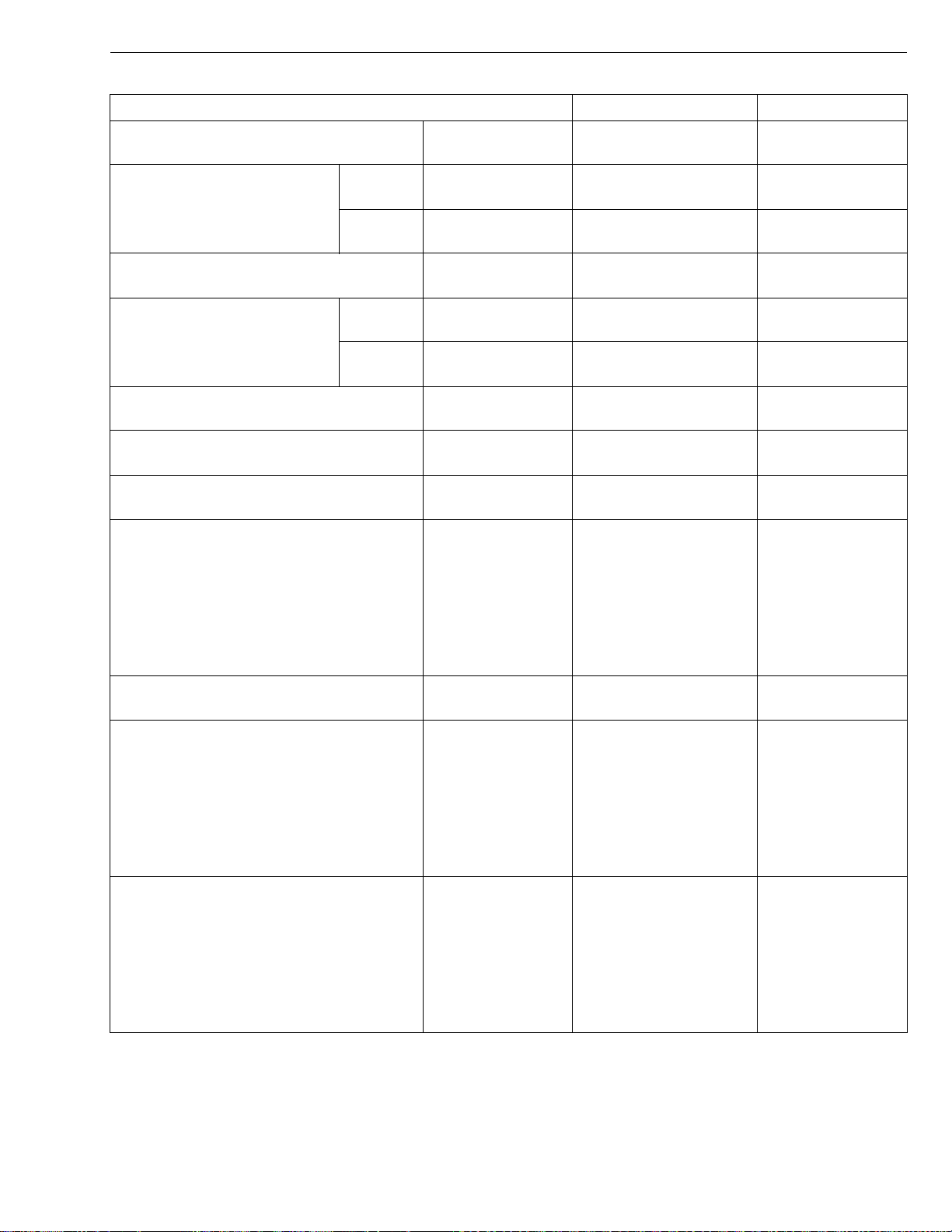
STα-30 · STα-35, WSM
KiSC issued 11, 2006 A
ENGINE BODY (Continued)
Item Factory Specification Allowable Limit
Piston Pin Bore I.D. 25.000 to 25.013 mm
0.98425 to 0.98476 in.
Second Ring to Ring Groove D1463-M Clearance 0.093 to 0.120 mm
0.00366 to 0.00472 in.
D1703-M Clearance 0.093 to 0.128 mm
0.00366 to 0.00504 in.
Oil Ring to Ring Groove Clearance 0.020 to 0.060 mm
0.00079 to 0.00205 in.
Top R ing D1463-M Ring Gap 0.20 to 0.35 mm
0.00787 to 0.01378 in.
D1703-M Ring Gap 0.25 to 0.40 mm
0.0098 to 0.0157 in.
Second Ring Ring Gap 0.30 to 0.45 mm
0.0118 to 0.0177 in.
Oil Ring Ring Gap 0.25 to 0.45 mm
0.0098 to 0.0177 in.
25.05 mm
0.9862 in.
0.2 mm
0.0079 in.
0.2 mm
0.0079 in.
0.15 mm
0.0059 in.
1.25 mm
0.0492 in.
1.25 mm
0.0492 in.
1.25 mm
0.0492 in.
1.25 mm
0.0492 in.
Connecting Rod Alignment – 0.05 mm
0.0020 in.
Piston Pin to Small End Bushing
Clearance
0.014 to 0.038 mm
0.00055 to 0.00150 in.
0.15 mm
0.0059 in.
ENGINE
Piston Pin
O.D.
25.002 to 25.011 mm
–
0.98433 to 0.98468 in.
Small End Bushing
I.D.
25.025 to 25.040 mm
–
0.98523 to 0.98582 in.
Crankshaft Alignment – 0.02 mm
0.00079 in.
Crankshaft Journal to Crankshaft Bearing
1
Crankshaft Journal
Oil Clearance
O.D.
0.040 to 0.118 mm
0.00157 to 0.00465 in.
51.921 to 51.940 mm
0.2 mm
0.0079 in.
–
2.04413 to 2.04488 in.
Crankshaft Bearing 1
I.D.
51.980 to 52.039 mm
–
2.04646 to 2.04878 in.
Crankshaft Journal to Crankshaft Bearing
2
Crankshaft Journal
Oil Clearance
O.D.
0.040 to 0.104 mm
0.00157 to 0.00409 in.
51.921 to 51.940 mm
0.2 mm
0.0079 in.
–
2.04413 to 2.04488 in.
Crankshaft Bearing 2
I.D.
51.980 to 52.025 mm
–
2.04646 to 2.04823 in.
W1013874
1-S7
Page 70
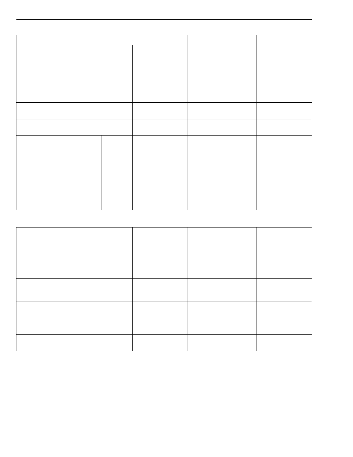
STα-30 · STα-35, WSM
KiSC issued 11, 2006 A
ENGINE BODY (Continued)
Crankpin to Crankpin Bearing
ENGINE
Item Factory Specification Allowable Limit
Oil Clearance
0.025 to 0.087 mm
0.00098 to 0.00343 in.
0.2 mm
0.0079 in.
Crankpin
O.D.
46.959 to 46.975 mm
1.84878 to 1.84941 in.
Crankpin Bearing
I.D.
47.000 to 47.046 mm
1.85039 to 1.85220 in.
Crankshaft Side Clearance 0.15 to 0.35 mm
0.0059 to 0.0138 in.
0.5 mm
0.0197 in.
Crankshaft Sleeve Wear – 0.1 mm
0.0039 in.
Cylinder Bore D1463-M I.D. (Standard)
I.D. (Oversize)
D1703-M I.D. (Standard)
I.D. (Oversize)
82.000 to 82.022 mm
3.22835 to 3.22921 in.
82.250 to 82.272 mm
3.23819 to 3.23906 in.
87.000 to 87.022 mm
3.42519 to 3.42606 in.
87.250 to 87.272 mm
3.43503 to 3.43590 in.
+ 0.15 mm
+ 0.0059 in.
+ 0.15 mm
+ 0.0059 in.
+ 0.15 mm
+ 0.0059 in.
+ 0.15 mm
+ 0.0059 in.
LUBRICATING SYSTEM
Engine Oil Pressure At Idle Speed
98 kPa or mor e
1.0 kgf/cm
2
14 psi or more
or more
49 kPa
0.5 kgf/cm
7 psi
–
–
W1013874
2
At Rated Speed
294 to 441 kPa
3.0 to 4.5 kgf/cm
43 to 64 psi
Engine Oil Pressure Switch Working Pressure 49 kPa
0.5 kgf/cm
2
7 psi
Inner Rotor to Outer Rotor Clearance 0.03 to 0.14 mm
0.0012 to 0.0055 in.
Outer Rotor to Pump Body Clearance 0.11 to 0.19 mm
0.0043 to 0.0075 in.
Inner Rotor to Cover End Clearance 0.105 to 0.150 mm
0.00413 to 0.00591 in.
2
2.5 kgf/cm
2
36 psi
–
0.2 mm
0.0079 in.
0.25 mm
0.0098 in.
0.2 mm
0.0079 in.
W1013973
245 kPa
1-S8
Page 71
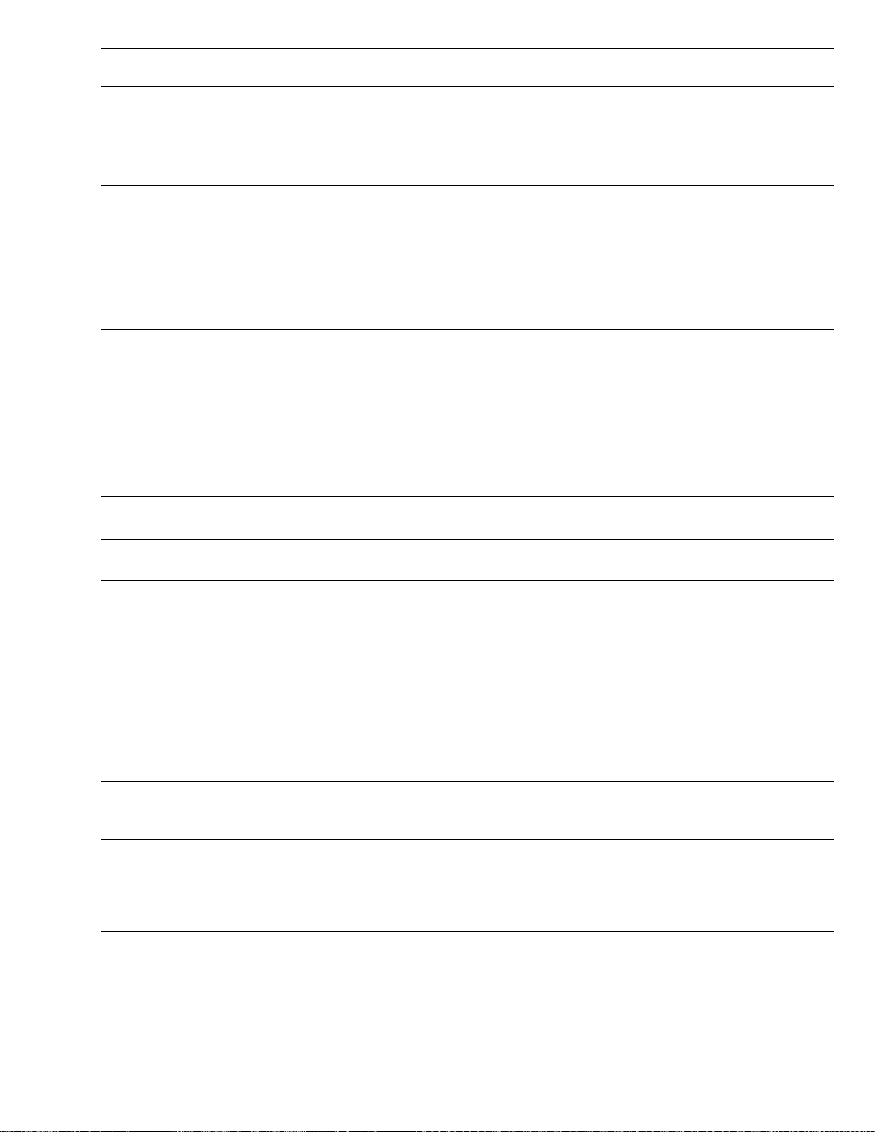
STα-30 · STα-35, WSM
KiSC issued 11, 2006 A
COOLING SYSTEM
Item Factory Specification Allowable Limit
Fan Belt Tension 7.0 to 9.0 mm (0.28 to
0.35 in.) deflection at
98 N (10 kgf, 22 lbs) of
force
Thermostat Valve Opening
Temperature
69.5 to 72.5 °C
157.1 to 162.5 °F
(At Beginning)
ENGINE
–
–
Valve Opening
Temperature
85 °C
185 °F
–
(Opened
Completely)
Radiator Water Tightness No leaks at
–
137 kPa
1.4 kgf/cm
2
20 psi
Radiator Cap Pressure Falling
Time
10 seconds or mo re f or
pressure falling
–
from 88 to 59 kPa
from 0.9 to 0.6 kgf/cm
2
from 13 to 9 psi
FUEL SYSTEM
Injection Pump Injection Timing 0.30 to 0.33 rad. (17 to
–
19 °) before T.D.C.
Pump Element Fuel Tightness – 14.7 MPa
150 kgf/cm
2133 psi
Delivery Valve Fuel Tightness 10 seconds or more for
pressure falling
from 14.7 to 13.7 MPa
from 150 to 140 kgf/cm
from 2133 to 1990 psi
5 seconds for
pressure falling
from 14.7 to
2
from 150 to
13.7 MPa
140 kgf/cm
from 2133 to
1990 psi
Injection Nozzle Injection Pressure 13.73 to 14.71 MPa
140 to 150 kgf/cm
2
–
1991 to 2133 psi
Injection Nozzle Valve Seat Valve Seat
Tightness
When the pressure is
12.75 MPa
(130 kgf/cm
2
, 1849 psi),
–
the valve seat must be
fuel tightness.
W1013874
2
2
W1013973
1-S9
Page 72
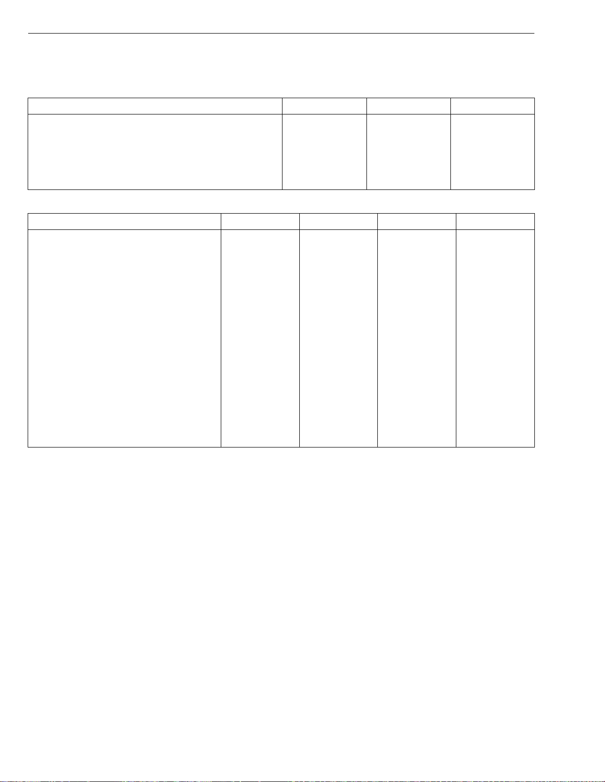
STα-30 · STα-35, WSM
NOTE■
KiSC issued 11, 2006 A
3. TIGHTENING TORQUES
Tightening torques of screws, bolts and nuts on the table below are especially specified.
(For general use screws, bolts and nuts : See page G-9.)
Item N·m kgf·m ft-lbs
Steering wheel mounting nut
Power steering delivery hose retaining nut
Steering hose LH and RH retaining nut
Engine mounting M10 screw, bolt and nut
Engine mounting M12 nut
Clutch cover mounting screw
Item Size x Pitch N·m kgf·m ft-lbs
Cylinder head cover screw
* Cylinder head screw
* Main bearing case screw 1
* Main bearing case screw 2
* Flywheel screw
* Connecting rod screw
* Rocker arm bracket screw
* Idle gear shaft screw
Fan drive pulley mounting nut
* Bearing case cover screw
Glow plug
Nozzle holder assembly
Nozzle holder
Oil Switch taper screw
Injection pipe retaining nut
Overflow pipe assembly retaining nut
Camshaft set screw
Hi-idling body
M6 × 1.0
M11 × 1.25
M9 × 1.25
M10 × 1.25
M12 × 1.25
M8 × 1.0
M8 × 1.25
M8 × 1.25
–
M8 × 1.25
M10 × 1.25
M20 × 2.0
–
PT 1/8
M12 × 1.5
–
M8 × 1.25
–
48.0 to 56.0
50 to 60
25 to 30
48.1 to 55.8
77.5 to 90.2
23.5 to 27.5
6.9 to 11.3
93.1 to 98.0
46.1 to 50.9
68.6 to 73.5
98.0 to 107.8
44.1 to 49.0
23.5 to 27.5
23.5 to 27.5
137.3 to 156.9
23.5 to 27.5
19.6 to 24.5
49.0 to 68.6
34.3 to 39.2
14.7 to 19.6
24.5 to 34.3
19.6 to 24.5
23.5 to 27.5
44.1 to 49.0
4.9 to 5.7
5.0 to 6.0
2.5 to 3.0
4.9 to 5.7
7.9 to 9.2
2.4 to 2.8
0.7 to 1.15
9.5 to 10.0
4.7 to 5.2
7.0 to 7.5
10.0 to 11.0
4.5 to 5.0
2.4 to 2.8
2.4 to 2.8
14.0 to 16.0
2.4 to 2.8
2.0 to 2.5
5.0 to 7.0
3.5 to 4.0
1.5 to 2.0
2.5 to 3.5
2.0 to 2.5
2.4 to 2.8
4.5 to 5.0
ENGINE
35.4 to 41.22
36.16 to 43.39
18.08 to 21.69
35.5 to 41.2
57.2 to 66.5
17.4 to 20.3
W1012736
5.1 to 8.32
68.7 to 72.3
34.0 to 37.6
50.6 to 54.2
72.3 to 79.5
32.5 to 36.2
17.4 to 20.3
17.4 to 20.3
101.3 to 115.7
17.4 to 20.3
14.5 to 18.1
36.2 to 50.6
25.3 to 28.9
10.8 to 14.5
18.1 to 25.3
14.5 to 18.1
17.4 to 20.3
32.6 to 36.3
• In removing and applying the screws, bolts and nuts marked with “*”, a pneumatic wrench or similar
pneumatic tool, if employed, must be used with enough care not to get them seized.
• For * marked screws, bolts and nuts on the table, apply engine oil to their threads and seats before
tightening.
• The letter “M” in Size x Pitch means that the screw, bolt or nut dimension stands for metric. The size is
the nominal outside diameter in mm of the threads. The pitch is the nominal distance in mm between two
threads.
W1013236
1-S10
Page 73
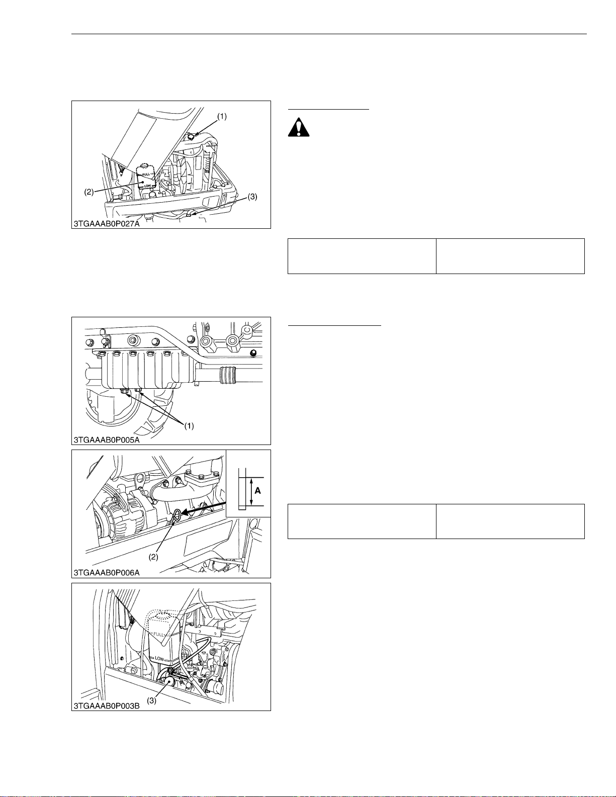
STα-30 · STα-35, WSM
IMPORTANT■
KiSC issued 11, 2006 A
4. CHECKING, DISASSEMBLING AND SERVICING
[1] SEPARATING ENGINE FROM TRACTOR
Draining Coolant
CAUTION
• Do not remove the radiator cap when the engine is hot. Then
loosen cap slightly to the stop to relieve any excess
pressure before removing cap completely.
1. Stop the engine and let cool down.
2. To drain the coolant, open the radiator drain plug (3) and remove
radiator cap (1). The radiator cap (1) must be removed to
completely drain the coolant.
3. After all coolant is drained, close the drain plug (3).
5.8 L
Coolant capacity (with recovery tank)
1.56 U.S.qts.
1.28 Imp.qts.
ENGINE
(1) Radiator Cap
(2) Recovery Tank
(3) Drain Plug
W1048932
Draining Engine Oil
1. Place an oil pan underneath the engine.
2. To drain the oil, remove the both drain plug (1) at the bo ttom of
the engine and drain the oil completely.
3. Screw in the both drain plug (1).
(When refilling)
• Fill the engine oil up to the upper line on the dipstick (2).
• When using an oil of different manufacture or viscosity from
the previous one, remove all of the old oil.
• Never mix two different types of oil.
• Use the proper SAE Engine Oil according to ambient
temperatures.
• Refer to “LUBRICANTS, FUEL AND COOLANT”. (See page
G-8.)
Engine oil capacity
(1) Drain Plug
(2) Dipstick
(3) Oil Inlet
4.5 L
1.19 U.S.qts.
0.99 Imp.qts.
(A) Oil level is acceptable within this
range.
W1050040
1-S11
Page 74
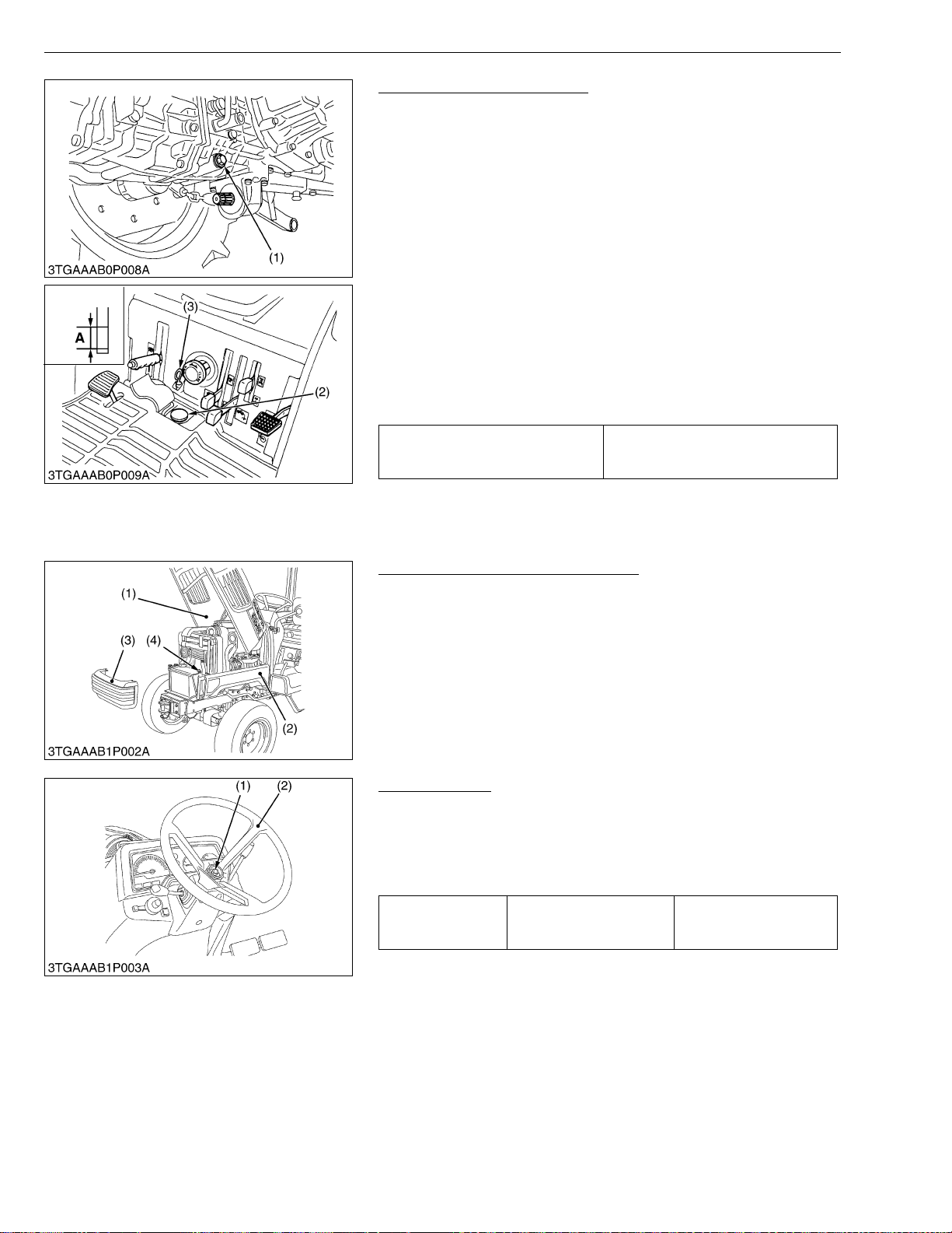
STα-30 · STα-35, WSM
IMPORTANT■
■
KiSC issued 11, 2006 A
ENGINE
Draining Transmission Fluid
1. Place oil pan underneath the transmission case, and remove the
drain plugs (1).
2. Drain the transmissio n fluid.
3. Reinstall the drain plug (1).
(When refilling)
• Fill new oil f rom f illi ng por t afte r rem aining the f illin g plug (2) up to
the upper notch on the dipstick (3).
• After running the engine for few minutes, stop it and check the oil
level again, if low, add oil prescribed level.
• Use only KUBOTA SUPER UDT fluid-Use of other oils may
damage the transmission or hydraulic system. Refer to
“LUBRICANTS, FUEL AND COOLANT”. (See page G-8.)
• Never work the tractor immediately after changing the
transmission oil. Keeping the engine at medium speed for a
few minutes to prevents damage to the transmission.
• Do not mix different blands oil together.
18.5 L
Transmission fluid capacity
4.89 U.S.gals.
4.07 Imp.gals.
(1) Drain Plug
(2) Filling Plug
(3) Dipstick
A : Oil level is acceptable within this
range.
W1012748
Hood, Side Cover and Battery Cord
1. Open the hood (1) and remove the front grille (3).
2. Disconnect the battery grounding cord (4).
3. Disconnect the head light connectors and remove the side covers
(2) and hood (1).
NOTE
• When disconnecting the battery cords, disconnect the
grounding cord first. When connecting, positive cord first.
(1) Hood
(2) Side Cover
(3) Front Grille
(4) Battery Cord
W1012749
Steering Wheel
1. Remove the steering wheel cap.
2. Remove the steering wheel mounting nut (1) and remove the
steering wheel (2) with a steering wheel puller (Code No. 07916-
51090).
(When reassembling)
Tightening torque
Steering wheel mounting
nut
48.04 to 56.0 N·m
4.9 to 5.7 kgf·m
35.4 to 41.22 ft-lbs
(1) Nut (2) Steering Wheel
W1012884
1-S12
Page 75
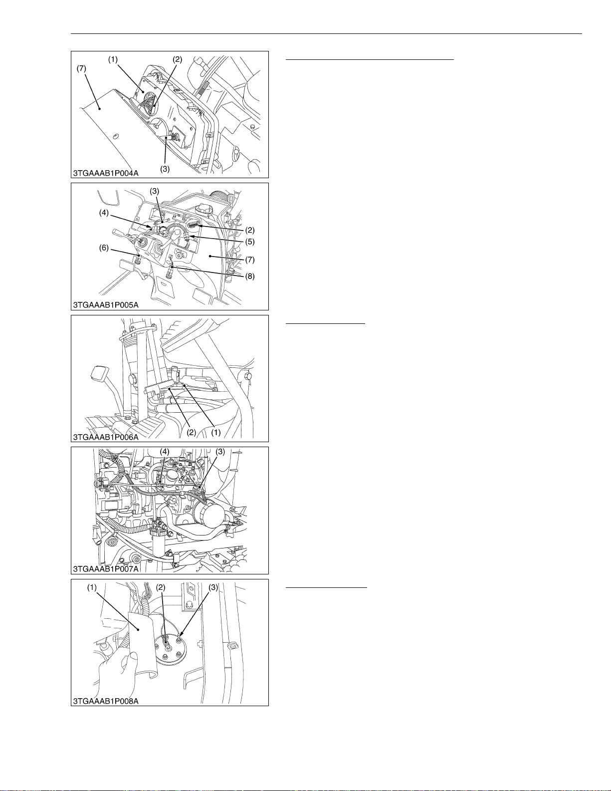
STα-30 · STα-35, WSM
IMPORTANT■
KiSC issued 11, 2006 A
ENGINE
Meter Panel and Panel Under Cover
1. Open the meter panel (1) and disconnect the meter panel
connector (2) and hour-meter cable (3). Then remove the meter
panel.
2. Remove the sponge.
3. Disconnect the combination switch connector (4), main switch
connector (5), hazard switch connector (6) and position lamp
switch connector (8).
4. Remove the panel under cover (7).
(1) Meter Panel
(2) Meter Panel Connector
(3) Hour-meter Cable
(4) Combination Switch Connector
(5) Main Switch Connector
(6) Hazard Switch connector
(7) Panel Under Cover
(8) Position Lamp Switch Connector
W1013015
Accelerator Wire
1. Remove the accelerator wire (1) from hand accelerator lever arm
(2).
2. Remove the accelerator wire (1) from speed control lever (3) and
holder (4).
• After assembling, b e sure to adjust the acce lerator wire to
speed control lever to operate the engine maximum speed.
• Be sure to check the acc elerator wire is not interfere with
power steering any hoses.
(1) Accelerator Wire
(2) Accelerator Lever Arm
(3) Speed Control Lever
(4) Holder
W1013265
Fuel Sensor Wire
1. Turn over the fuel sensor cover (1).
2. Disconnect the 1P connector (2) and ground wire (3) from the fuel
sensor.
(1) Fuel Sensor Cover
(2) 1P Connector
(3) Ground Wire
W1052606
1-S13
Page 76
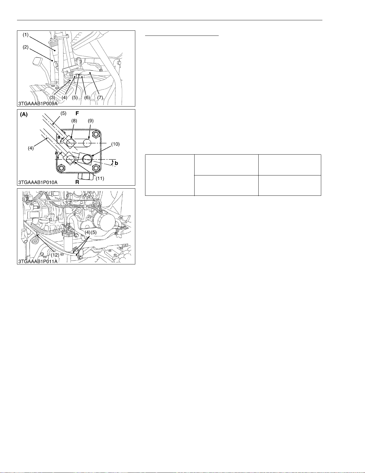
STα-30 · STα-35, WSM
KiSC issued 11, 2006 A
ENGINE
Power Steering Controller
1. Disconnect the draining hose (7), power stering delivery hose (3),
steering hose RH (4) and steering hose LH (5).
2. Remove the power steering controller (1) with steering pillar (2).
(When reassembling)
• Connect the steering hose LH (5) to LT port (8).
• Connect the s teering hose RH (4) with wh ite tap e (6) to RT port
(11).
• Make arrangement the hose as figure and routing to original.
• When reassembling the controller with steering pillar to the panel
under frame and under frame, temporally screw in the four
screws then tighten first to panel under frame (upper side) side in
parallel between panel under frame an d screw plate o f steering
pillar.
• Be sure to clamp the delivery hoses (4) and (5) to position
hydraulic delivery pipe with clamp band (12).
• Be sure to check the hoses are not interfere with accelerator wire.
Power steering delivery
hose retaining nut
Tightening torque
Steering hose LH and RH
retaining nut
50 to 60 N·m
5.0 to 6.0 kgf·m
36.16 to 43.39 ft-lbs
25 to 30 N·m
2.5 to 3.0 kgf·m
18.08 to 21.69 ft-lbs
(1) P ower Steering Controller
(2) Steering Pillar
(3) Power Steering Delivery Hose
(4) Steering Hose RH
(5) Steering Hose LH
(6) White Tape
(7) Drain Hose
(8) LT Port
(9) Drain Port
(10) Delivery Port
(11) RT Port
(12) Clamp Band
(A) Viewed from Bottom Side
F : Front
R : Rear
a : 0.785 rad. (45 °)
b : 0.174 to 0.262 rad. (10 to 15 °)
W1052855
1-S14
Page 77
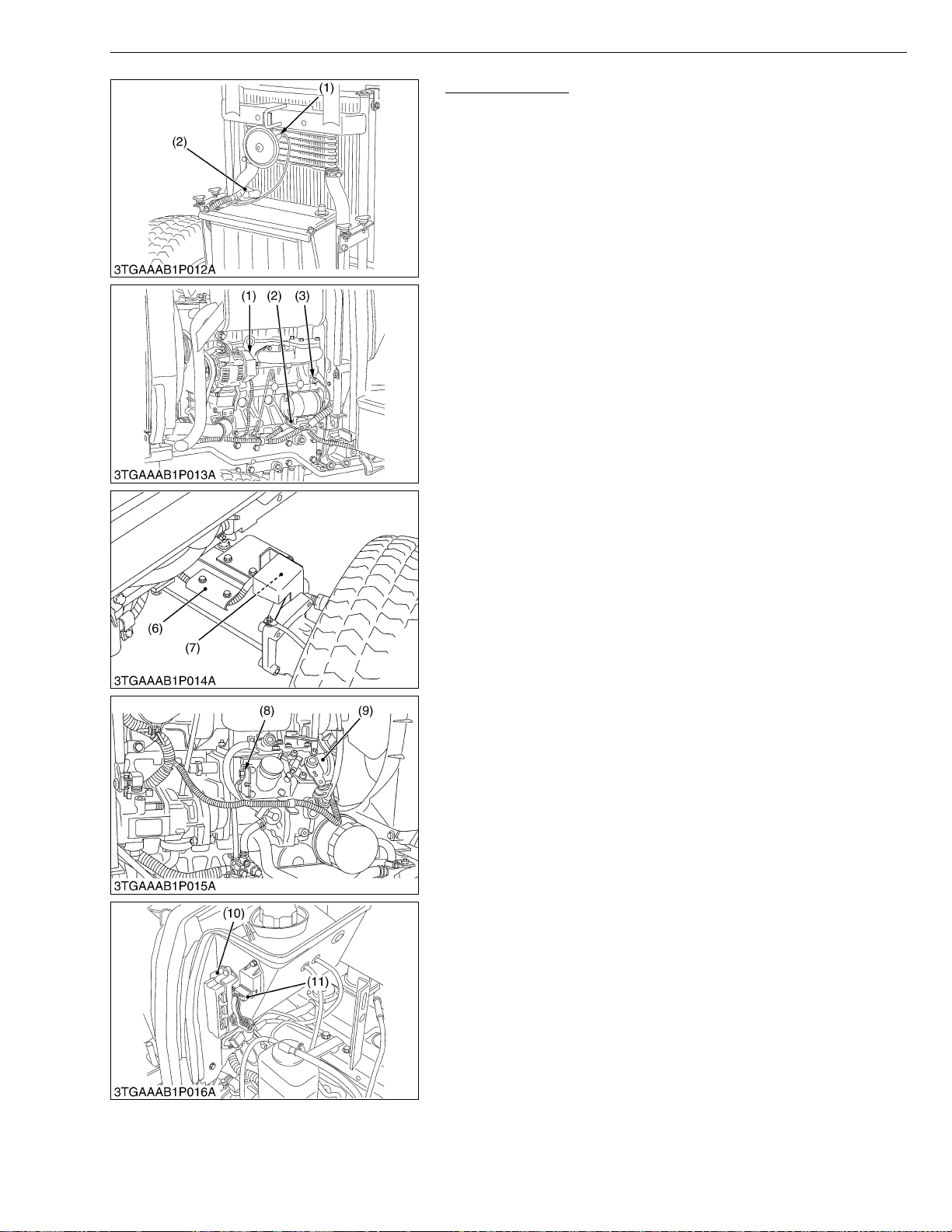
STα-30 · STα-35, WSM
KiSC issued 11, 2006 A
ENGINE
Wire Connectors
1. Remove or disco nne ct the connectors, termin al s a s li ste d be low
and figures.
2. Remove the harness from each harness clamp.
3. Remove the fuse box mounting screws, and remove the fuse box
assembly (10).
(1) Horn
(2) Battery Positive Code
(3) Alternator
(4) Starter
(5) Engine Oil Pressure Switch
(6) Harness G uide
(7) Front Wheel Turning Angle Sensor
(8) Ground Terminal
(9) Stop Solenoid
(10) Fuse Box Assembly
(11) Timer Relay
W1045601
1-S15
Page 78
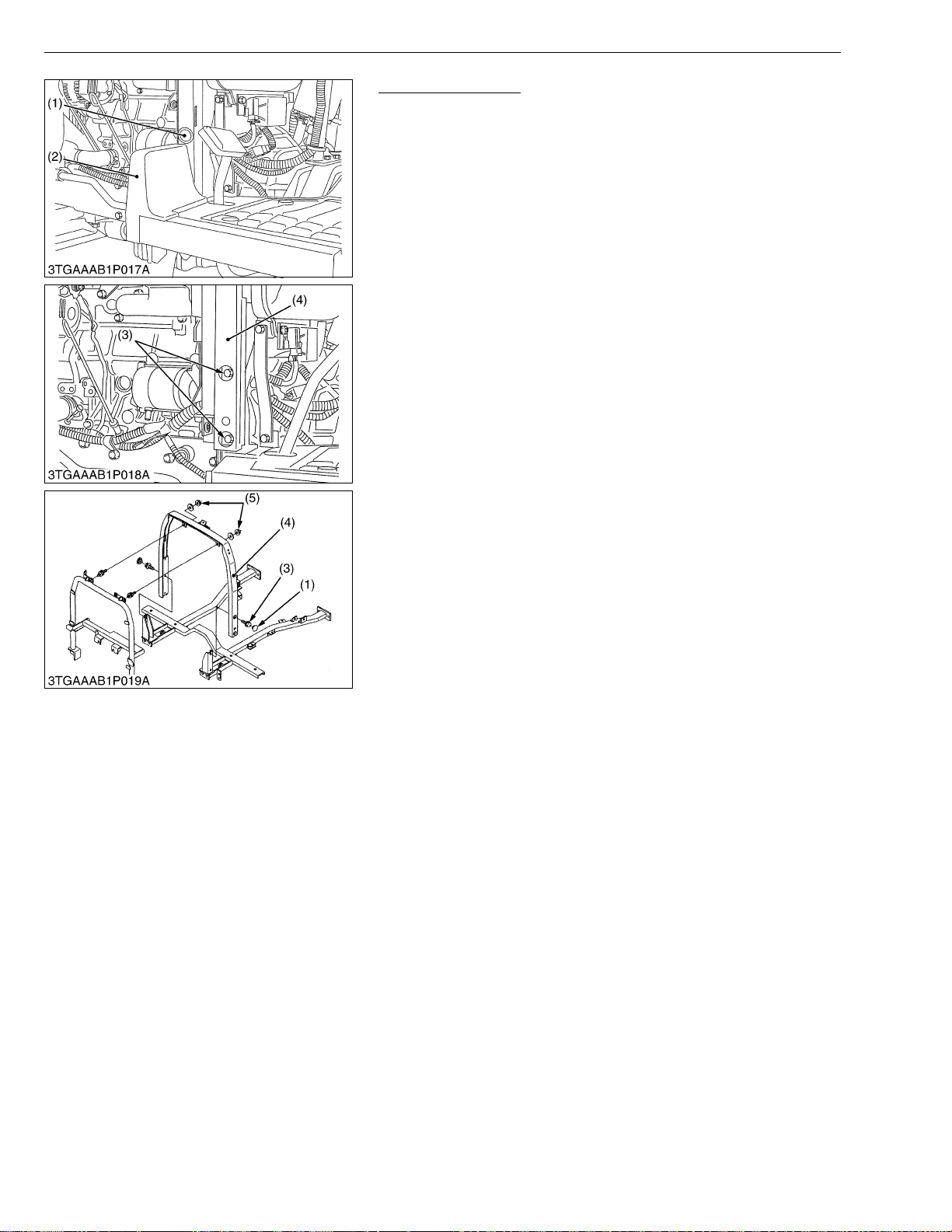
STα-30 · STα-35, WSM
KiSC issued 11, 2006 A
ENGINE
Panel Under Frame
1. Remove the foot cover (2), step stay and plug (1).
2. Remove the panel under frame mounting screw (3) and nut, pull
up the panel under frame (4) to remove it.
(When reassembling)
• When reassemb ling the p anel un der fr ame, tigh ten t he two nu ts
(5) for insulation rubber first.
(1) Plug
(2) Foot Cover
(3) Screw
(4) Panel Under Cover
(5) Nut
W1055726
1-S16
Page 79
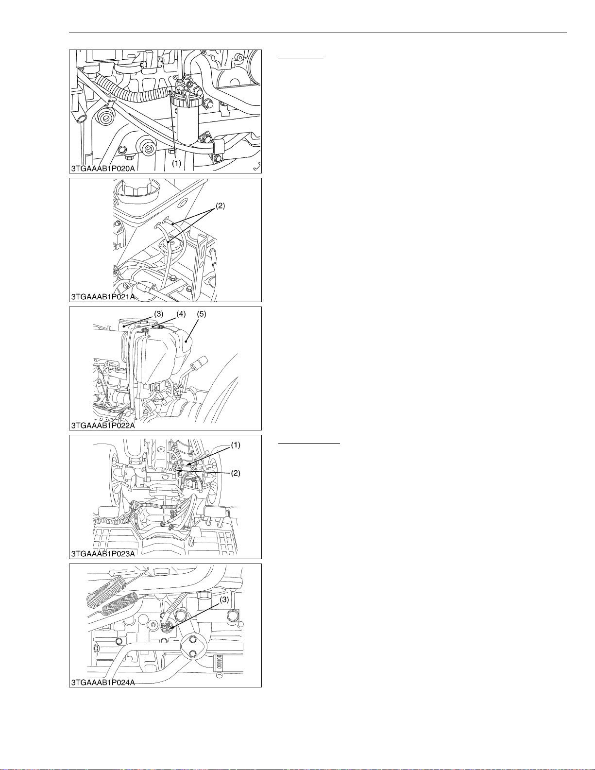
STα-30 · STα-35, WSM
KiSC issued 11, 2006 A
ENGINE
Fuel Tank
1. Disconnect the fuel hose (1) at the fuel filter side, then drain fuel
completely.
2. Remove the air cleaner assembly.
3. Disconnect the overflow hoses (2) of fuel line.
4. Remove the bonnet rear support (4), shutter plate (3) with fuel
tank (5).
(When reassembling)
• Be sure to fix the sponges to the original position.
(1) Fuel Hose
(2) Overflow Hose
(3) Shutter Plate
(4) Bonnet Rear Support
(5) Fuel Tank
W1055997
Wire Harness
1. Remove the glow plug cable (1).
2. Disconnect the 1P connector from the coolant temperature
sensor (2).
3. Disconnect the coupler from bi-speed solenoid (3).
4. Remove the wire harness assembly.
(1) Glow Plug Code
(2) Coolant Temperature Sensor
(3) Bi-speed Solenoid
W1057013
1-S17
Page 80
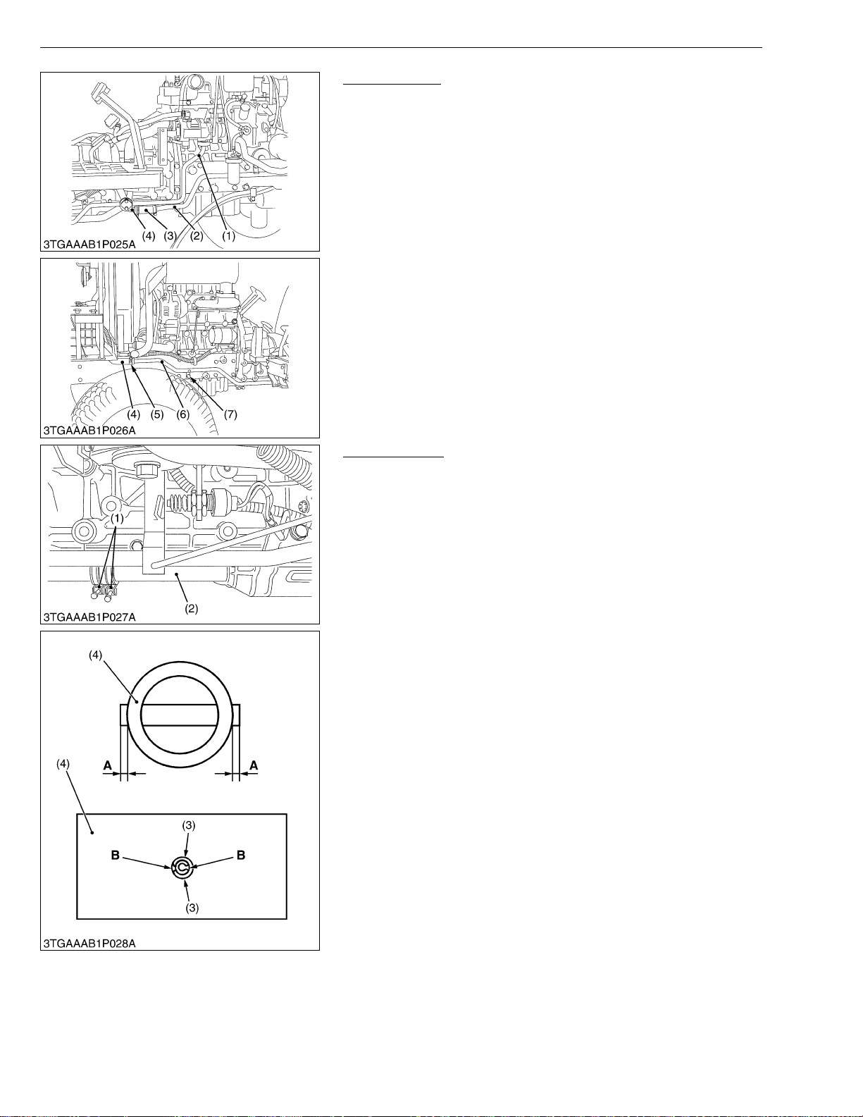
STα-30 · STα-35, WSM
KiSC issued 11, 2006 A
ENGINE
Hydraulic Pipe
1. Remove the hydraulic delivery pipe (1) from the 3P hydraulic
pump.
2. Loosen the ho se band of the joint hose (3) and slide the joi nt
hose (3) to s eparating t he HST drai n pipe (2) and inlet pipe ( 4).
3. Remove the pipe clamping screws.
4. Loosen the hose band (5) and separate the HST pipe (6) from the
HST drain hose (4).
5. Remove the HST pipe (6) clamping screw (7).
(1) Hydraulic Delivery Pipe
(2) HST Drain Pipe
(3) Joint Hose
(4) Inlet Pipe
(5) Hose Band
(6) HST Pipe
(7) Clamping Screw
W1057369
Propeller Shaft
1. Loosen the clamp (1) and slide the propeller shaft cover (2).
2. Tap out the spring pin (3) and then slide the coupling (4).
3. Remove the propeller shaft with cover.
(When reassembling)
• Apply grease to the splines of the propeller shaft and couplings.
• When inserting the spring pins (3), face their splits in the direction
parallel to the universal joint as shown in the figure.
(1) Clamp
(2) Propeller Shaft Cover
(3) Spring Pin
(4) Coupling
A : Approx. 1.0 mm (0.039 in.)
B : Split Portion
W1014306
1-S18
Page 81
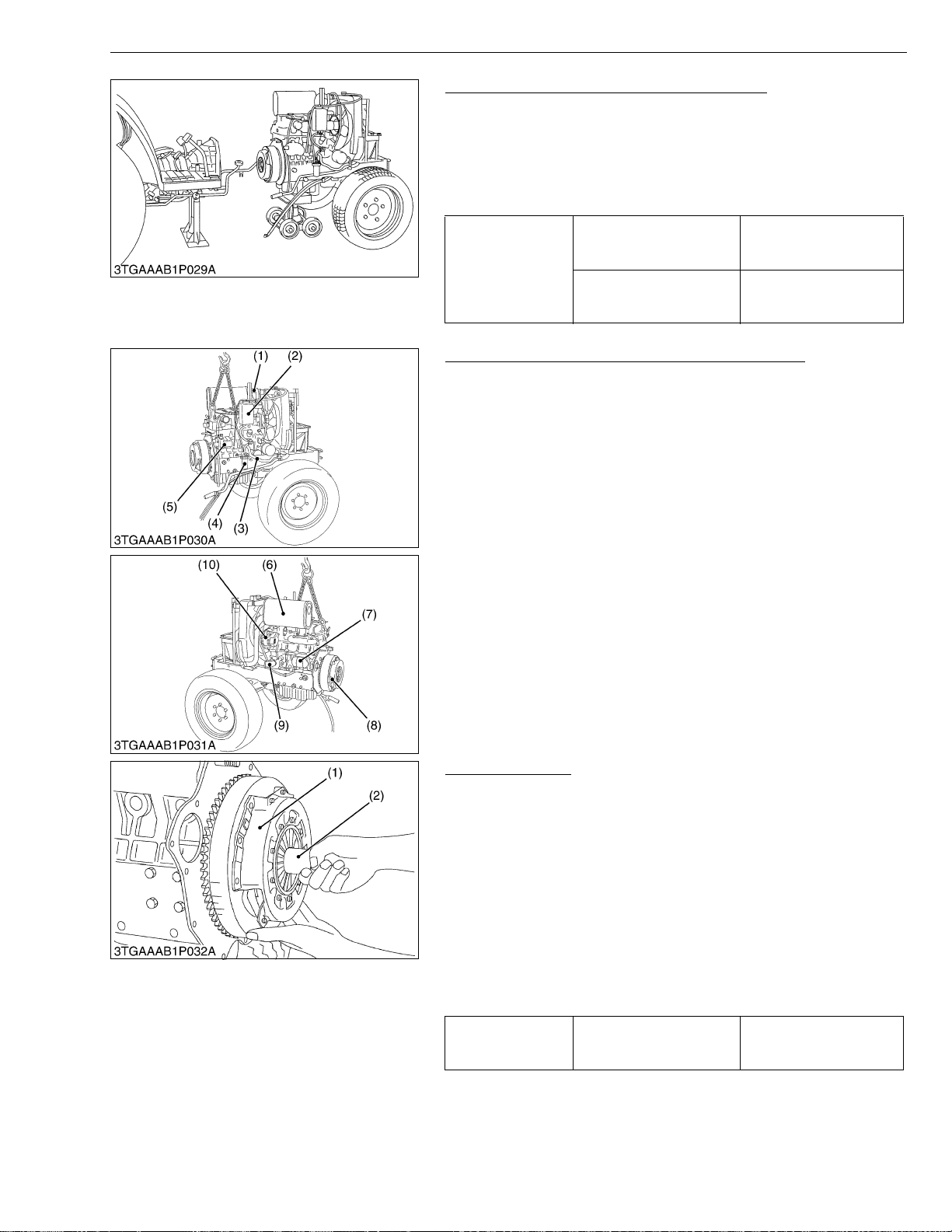
STα-30 · STα-35, WSM
■
■
KiSC issued 11, 2006 A
ENGINE
Separating the Engine from Clutch Housing
1. Place the jack under the center frame and engine oil pan.
2. Remove the engine mounting screws, bolts and nuts, and
separate the engine from the clutch housing.
(When reassembling)
• Apply liquid gasket (Three Bond 1208D or equivalent) to joint
face of the engine and clutch housing.
Engine mounting M10
screw, bolt and nut
Tightening torque
Engine mounting M12 nut
48.1 to 55.8N·m
4.9 to 5.7 kgf·m
35.5 to 41.2 ft-lbs
77.5 to 90.2 N·m
7.9 to 9.2 kgf·m
57.2 to 66.5 ft-lbs
W1056610
Separating Front Axle Assembly and Outer Parts
1. Disconnect the radiator hoses (1), (3) and (9).
2. Remove the muffler (6).
3. Remove the recovery tank (2).
4. Remove the stater motor (7) and alternator (10).
5. Remove the fuel filter (4) and hydraulic pump (5).
6. Remove the engine mounting screws and separate the front axle
assembly from engine.
(1) Radiator Hose
(2) Recovery Tank
(3) Radiator Hose
(4) Fuel Filter
(5) Hydraulic Pump
(6) Muffler
(7) Stater Motor
(8) Clutch Assembly
(9) Radiator Hose
(10) Alternator
W1058184
Clutch Assembly
1. Remove the clutch assembly (1).
(When reassembling)
• Direct the shorter end of the clutch disc boss toward the flywheel.
• Apply molybdenum di sulphide (Thre e Bond 1901 or equiva lent)
to the splines of clutch disc boss.
• Make sure of reamer scr ews posi tio n and after two reamer bolts
are tightened, other screws are tightened.
IMPORTANT
• Be sure to align the center of disc and flywheel by inserting
the clutch center tool (2).
NOTE
• Do not allow grease and oil on the clutch disc facing.
Tightening torque
(1) Clutch Assembly (2) Clutch Center Tool
Clutch cover mounting
screws
23.5 to 27.5 N·m
2.4 to 2.8 kgf·m
17.5 to 20.3 ft-lbs
W1017588
1-S19
Page 82
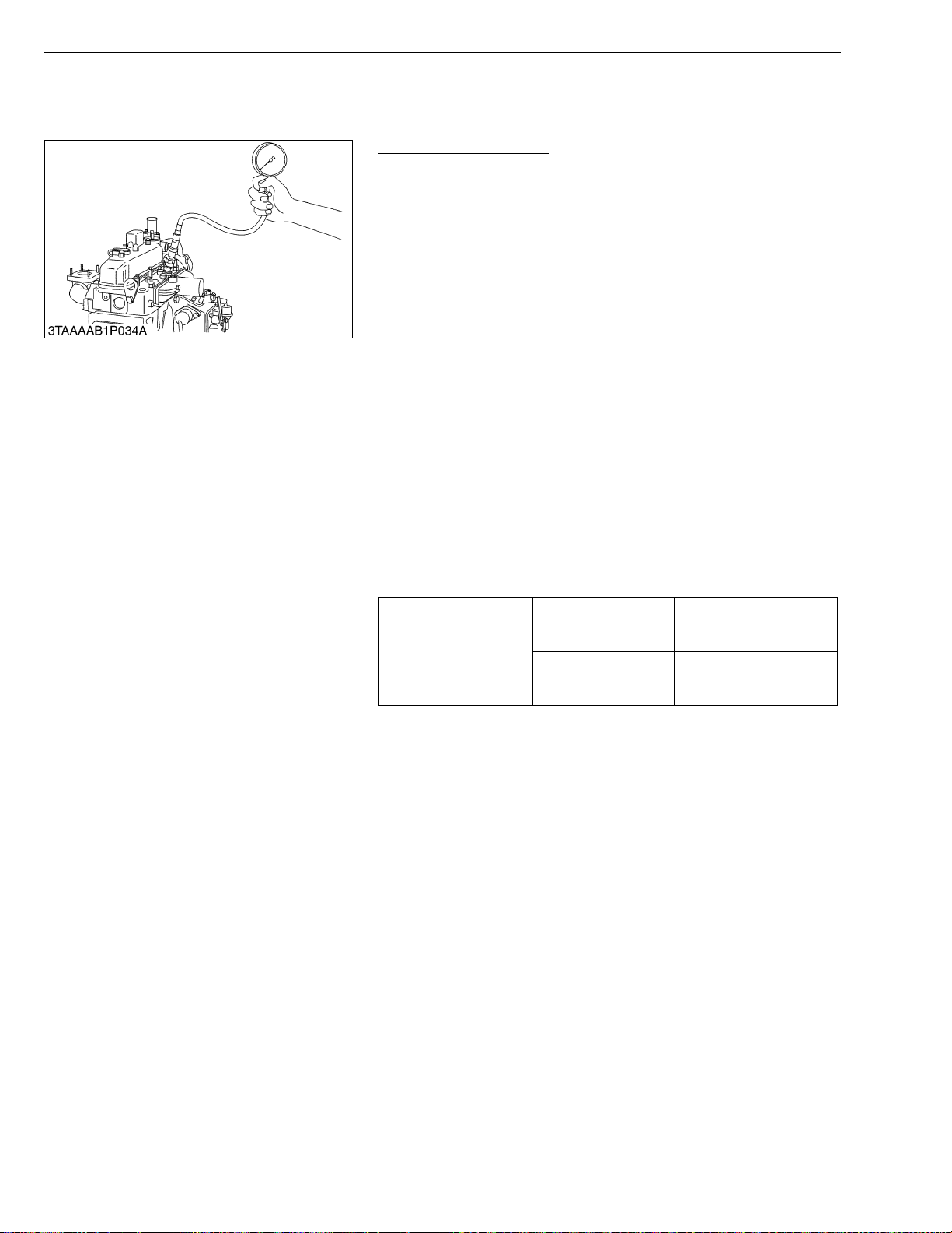
STα-30 · STα-35, WSM
NOTE■
KiSC issued 11, 2006 A
[2] ENGINE BODY
(1) Checking and Adjusting
ENGINE
Compression Pressure
1. Run the engine until it is warmed up.
2. Stop the engine and disconnect the 2P connector from the fuel
pump.
3. Remove the air cleaner, the muffler and all injection nozzles.
4. Set a compression tester (Code No. 07909-30208) with the
adaptor to the nozzle hole.
5. Keep the engine stop lever at “Stop Position”.
6. While cranking the engine with the starter, measure the
compression pressure.
7. Repeat steps 4 through 6 for each cylinder.
8. If the measureme nt is below the allowable limit, apply a small
amount of oil to the cylinder wall through the nozzle hole and
measure the compression pressure again.
9. If the compressio n pressure is still l ess than the allowab le limit,
check the top clearance, valve and cylinder head.
10.If th e compression pressure increa ses after applying oil, chec k
the cylinder wall and piston rings.
• Check the compression pressure with the specified valve
clearance.
• Always use a fully charged battery for performing this test.
• Variances in cylinder compression values should be under
10 %.
Compression pressure
Factory spec.
Allowable limit
3.53 to 4.02 MPa
36 to 41 kgf/cm
512 to 583 psi
2.55 MPa
26 kgf/cm
370 psi
2
2
W1018639
1-S20
Page 83
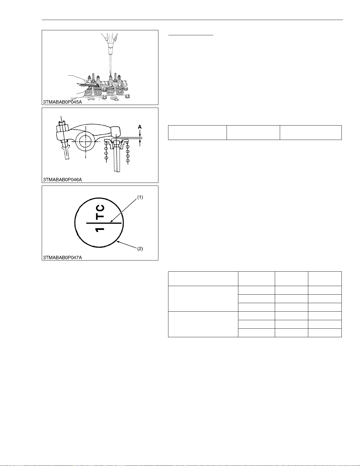
STα-30 · STα-35, WSM
IMPORTANT■
NOTE■
KiSC issued 11, 2006 A
ENGINE
Valve Clearance
• Valve clearance must be checked and adjusted when engine
is cold.
1. Remove the head cov er, the glow plugs and the timing windo w
cover on the clutch housing.
2. Align the “1TC” mark lin e on the flywheel and cent er of timing
window so that the No. 1 piston comes to the compression or
overlap top dead center.
3. Check the following valve clearance marked with “✩” using a
feeler gauge.
4. If the clearance is not within the factory specifications, adjust with
the adjusting screw.
Valve clearance Factory spec.
0.18 to 0.22 mm
0.0071 to 0.0087 in.
• The “TC” marking line on the flywheel is just for No. 1
cylinder. There is no “TC” marking for the other cylinders.
• No. 1 piston comes to the T.D.C. position when the “TC”
marking is aligned with center of timing window on clutchhousing. Turn the flywheel 0.26 rad. (15 °) clockwise and
counterclockwise to see if the piston is at the compression
top dead center or the overlap position. Now referring to the
table below, readjust the valve cle arance. (The piston is at
the compression top dead center when both the IN. and EX.
valves do not move; it is at the overlap posit ion when both
the valves move.)
• Finally turn the flyw heel 6.28 ra d. (360 ° ) and align the “T C”
marking line and the center of timing window. Adjust all the
other valve clearance as required.
• After turning the flywheel counterclockwise twice or three
times, recheck the valve clearance , firmly tighten the lock
nut of the adjusting screw.
Condition
When No. 1 piston is
compression top dead center
When No. 1 piston is overlap
position
No. of
cylinder
1st ✩✩
2nd ✩
3rd ✩
1st
2nd ✩
3rd ✩
IN. Valve EX. Valve
(1) TC Mark Line
(2) Timing Window
1-S21
A : Valve Clearance
W1018974
Page 84
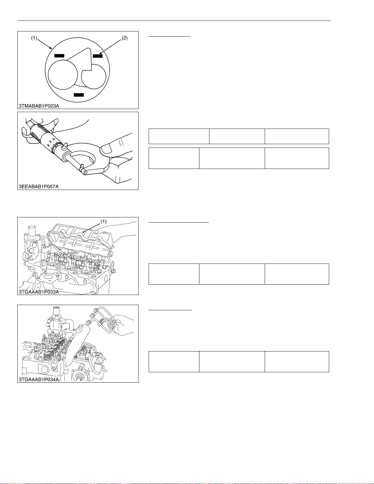
STα-30 · STα-35, WSM
KiSC issued 11, 2006 A
ENGINE
Top Clearance
1. Remove the cylinder head.
2. Move the piston up and stick a strip of fuse on the piston head at
three position with grease.
3. Lower the piston and install the cylinder head. (Use a new
cylinder head gasket and tighten with a specified tightening
torque.)
4. Turn the flywheel until the piston passes through the T.D.C..
5. Remove the cylinder head and measure the thickness of the
fuses.
6. If the measurement is not within the factory specifications, check
the oil clearances between the crankpin and bearing and
between the piston pin and bushing.
Top clearance Factory spec.
Tightening torque Cylinder head screws
(1) Piston (2) Fuse
0.55 to 0.70 mm
0.0217 to 0.0276 in.
93.1 to 98.0 N·m
9.5 to 10.0 kgf·m
68.7 to 72.3 ft-lbs
W1020190
(2) Disassembling and Assembling
(A) Cylinder Head and Valves
Cylinder Head Cover
1. Remove the breather hose.
2. Remove the head cover screws.
3. Remove the cylinder head cover (1).
(When reassembling)
• Check to see if the cylinder head cover gasket is not defective.
6.9 to 11.3 N·m
Tightening torque Cylinder head cover screw
(1) Cylinder Head Cover
0.7 to 1.15 kgf·m
5.1 to 8.32 ft-lbs
W1020618
Injection Pipes
1. Loosen the screws on the pipe clamps.
2. Detach the injection pipes.
(When reassembling)
• Sent compressed air into the pipes to blow out dust. Then,
reassemble the pipes in the reverse order.
24.5 to 34.3 N·m
Tightening torque Injection pipe retaining nut
2.5 to 3.5 kgf·m
18.1 to 25.3 ft-lbs
W1020811
1-S22
Page 85
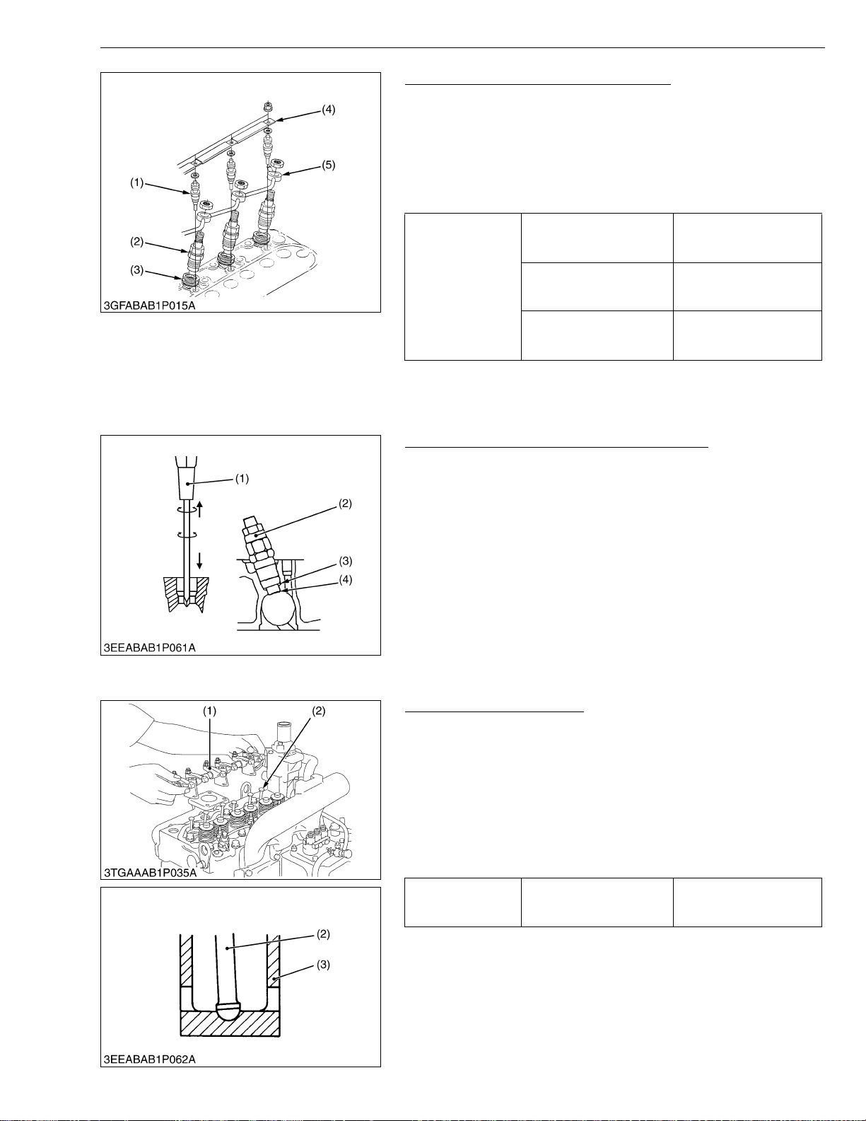
STα-30 · STα-35, WSM
■
IMPORTANT■
KiSC issued 11, 2006 A
ENGINE
Nozzle Holder Assembly and Glow Plug
1. Remove the overflow pipe assembly (5).
2. Remove the nozzle holder assembl ies (2) using a 21 mm deep
socket wrench.
3. Remove the copper gasket and heat seal (3).
4. Remove the glow plugs (1).
(When reassembling)
• Replace the copper gasket and heat seal with new one.
49.0 to 68.6 N·m
Tightening torque
Nozzle holder assembly
Overflow pipe assembly
retaining nut
Glow plug
5.0 to 7.0 kgf·m
36.2 to 50.6 ft-lbs
19.6 to 24.5 N·m
2.0 to 2.5 kgf·m
14.5 to 18.1 ft-lbs
19.6 to 24.5 N·m
2.0 to 2.5 kgf·m
14.5 to 18.1 ft-lbs
(1) Glow Plug
(2) Nozzle Holder Assembly
(3) Heat Seal
(4) Lead
(5) Overflow Pipe Asse mbly
W1020917
Nozzle Heat Seal Service Removal Procedure
IMPORTANT
• Use a plus (phillips head) screw driver (1) that has a Dia.
which is bigger than the heat seal hole (Approx. 6 mm) 1/4 in.
1. Drove screw drive (1) lightly into the heat seal hole.
2. Turn screw driver three or four times each way.
3. While turning the s crew driver, slowly pull the he at seal (4) out
together with the c opper gasket (3).
4. If the heat seal drops, repeat the above procedure.
(When reassembling)
• Heat seal and copper gasket must be changed when the injection
nozzle is removed for cleaning or for service.
(1) Plus Screw Driver
(2) Nozzle Holder
(3) Copper Gasket
(4) Heat Seal
W1021255
Rocker Arm and Push Rod
1. Remove the rocker arm bracket mounting bolts.
2. Detach the rocker arm assembly (1).
3. Remove the push rods (2).
(When reassembling)
• When putting the push rods (2) onto the tappets (3), check to see
if their ends are properly engaged with the grooves.
• After installing the rocker arm, be sure to a djust the valve
clearance.
Tightening torque
(1) Rocker Arm Assem bly
(2) Push Rod
Rocker arm bracket
mounting bolt
(3) Tappet
23.5 to 27.5 N·m
2.4 to 2.8 kgf·m
17.4 to 20.3 ft-lbs
W1021437
1-S23
Page 86
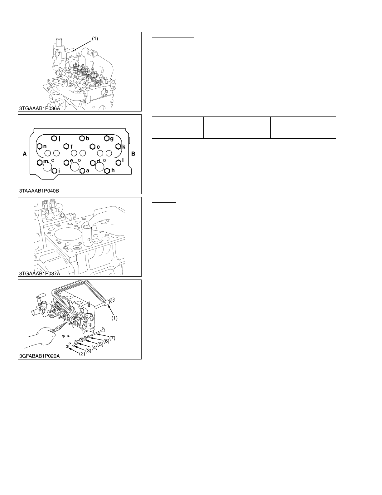
STα-30 · STα-35, WSM
IMPORTANT■
IMPORTANT■
KiSC issued 11, 2006 A
ENGINE
Cylinder Head
1. Loosen the pipe clamp, and remove the water return pipe (1).
2. Remove the cylinder head screw in the order of (n) to (a).
3. Lift up the cylinder head to detach.
4. Remove the cylinder head gasket.
(When reassembling)
• Replace the cylinder head gasket with a new on.
• Tighten the cylinder head screws after applying sufficient oil.
• Tighten the cylinder head screws in diagonal sequence starting
from the center.
• Tighten them uniformly, or the head may deform in the long run.
93.1 to 98.0 N·m
Tightening torque Cylinder head screw
9.5 to 10.0 kgf·m
68.7 to 72.3 ft-lbs
(1) Return Pipe (n) to (a): To Loosen
(a) to (n): To Tighten
(A) Gear Case Side
(B) Flywheel Side
W1021755
Tappets
1. Remove the tappets from the crankcase.
(When reassembling)
• Visually check the contact between tappets and cams for proper
rotation. If defect is found, replace tappets.
• Before installing the tappets, apply engine oil thinly around them.
• Do not change the combination of tappet and tappet guide.
W1022001
Valves
1. Remove the valve caps (2).
2. Remove the valve spring collet (3), pushing the valve spring
retainer (4) by valve spring replacer (1).
3. Remove the val ve spri ng reta iner (4 ), valve spri ng (5) an d valv e
stem seal (6).
4. Remove the valve (7).
(When reassembling)
• Wash the va lve s tem and valve guid e hole, and apply eng ine oi l
sufficiently.
• After installing the valve spring collets, lightly tap the stem to
assure proper fit with a plastic hammer.
• Don’t cha nge the combination of valve and valve guide.
(1) Valve Spring Replacer
(2) Valve Cap
(3) Valve Spring Collet
(4) Valve Spring Retainer
(5) Valve Spring
(6) Valve Stem Seal
(7) Valve
W1022102
1-S24
Page 87
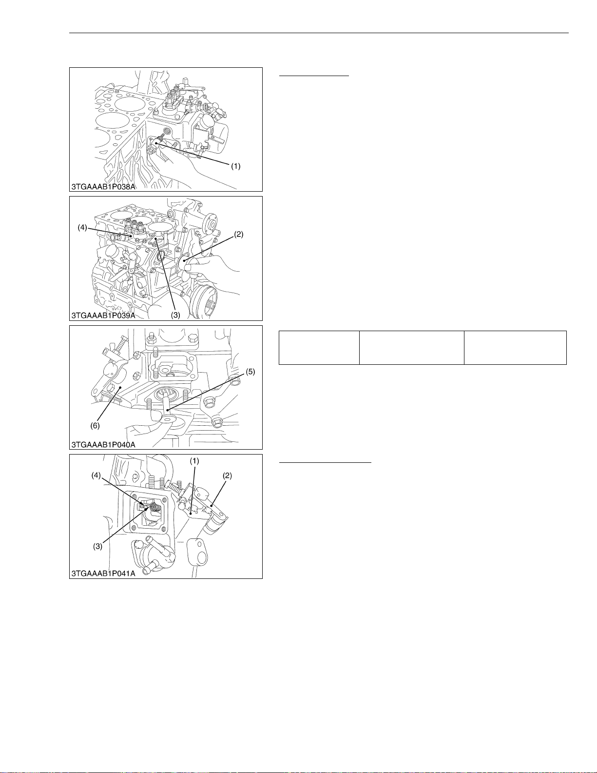
STα-30 · STα-35, WSM
IMPORTANT■
KiSC issued 11, 2006 A
(B) Timing Gears, Camshaft and Fuel Camshaft
Injection Pump
1. Remove the stop solenoid (2) and hi-idling body (1).
2. Remove the engine stop lever (3) and stop solenoid guide (5).
3. Remove the cover (6).
4. Remove the fuel injection pump assembly (4).
• Before removing the injection pump assembly, be sure to
remove the stop solenoid, hi-idling body, engine stop lever
and stop solenoid guide (5).
(When reassembling)
• Before attachin g the stop solenoid, hi-idling body an d solenoid
guide, install the injection pump first into position.
• Replace the hi-idling body gasket with a new one.
• Before fitting the stop lever to the gear case , install th e so lenoid
guide first into position. Then attac h the stop lever an d use it to
see if it functions well.
• Before fitting the id li ng lim ite r in pl ac e, a ttac h th e so le noi d gu ide
and the engine stop lever in their respective positions.
• When installing the stop s olenoid, be careful to ke ep the O-r ing
in place.
• Be sure to insert the pus h rod of the stop soleno id into the hole
at the center of the solenoid guide.
Tightening torque Hi-idling body
ENGINE
44.1 to 49.0 N·m
4.5 to 5.0 kgf·m
32.6 to 36.3 ft-lbs
(1) Hi-idling Body
(2) Stop Solenoid
(3) Stop Lever
(4) Injection Pump Assembly
(5) Solenoid Guide
(6) Cover
W1023686
Speed Control Plate
1. Disconnect the governor spring (3), (4).
2. Remove the speed control plate (1).
(When reassembling)
• Check that the speed control lever (2) positions low idle, af ter
assembling governor spring.
• Check that the speed control lever returns to the high idle position
rather than the low idle position, after moving the lever to the
maximum speed position.
• After assembling the engi ne, check the idli ng speed referring to
Adjusting Idling Speed. (950 to 1000 rpm)
(1) Speed Control Plate
(2) Speed Control Lever
(3) Governor Spring 1
(4) Governor Spring 2
W1024090
1-S25
Page 88
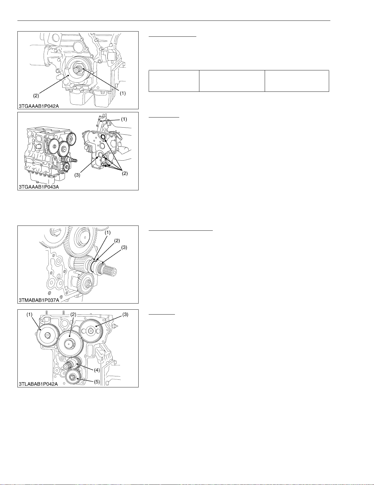
STα-30 · STα-35, WSM
KiSC issued 11, 2006 A
ENGINE
Fan Drive Pulley
1. Lock the flywheel not to turn using the flywheel stopper.
2. Remove the fan drive pulley mounting nut.
3. Remove the fan drive pulley (2) with gear puller.
(When reassembling)
Tightening torque
(1) Nut (2) Fan Drive Pulley
Fan drive pulley mounting
nut
137.3 to 156.9 N·m
14.0 to 16.0 kgf·m
101.3 to 115.7 ft-lbs
W1024348
Gear Case
1. Remove the hour meter gear case.
2. Remove the gear case (1).
3. Remove the O-rings (2 ).
(When reassembling)
• Apply liquid gasket (Three Bond 1215 or equivalent) to both side
of hour meter gear case gasket.
• Check to see if there are four O-rings (2) inside the gear case (1).
• Apply a thin film of engine oil to the oil seal (3), and insta ll it,
noting the lip come off.
• Before installing the gear case gasket, apply a non-drying
adhesive.
(1) Gear Case
(2) O-ring
(3) Oil Seal
W1024531
Crankshaft Oil Slinger
1. Remove the feather key.
2. Remove the crankshaft collar (3).
3. Remove the O-ring (2).
4. Detach the crankshaft oil slinger (1).
(When reassembling)
• Insert the crankshaft collar (3) after install the gear case to
cylinder body
(1) Crankshaft Oil Slinger
(2) O-ring
(3) Crankshaft Collar
W1024731
Idle Gear
1. Remove the external snap ring.
2. Detach the idle gear collar.
3. Detach the idle gear (2).
(When reassembling)
• Check to see each gear is aligned with its aligning mark:
(1) Idle gear and crank gear
(2) Idle gear and camshaft gear
(3) Idle gear and injection pump gear
(1) Injection Pump Gear
(2) Idle Gear
(3) Cam Gear
(4) Crank Gear
(5) Oil Pump Drive Gear
W1024941
1-S26
Page 89
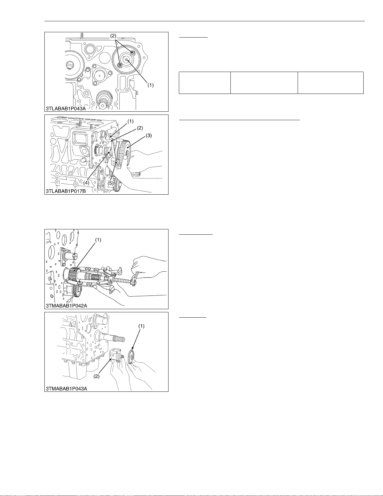
STα-30 · STα-35, WSM
KiSC issued 11, 2006 A
ENGINE
Camshaft
1. Remove the camshaft set bolts and draw out the camshaft (1).
(When reassembling)
• When installing the idle gear, be sure to align the alignment
marks on gears.
23.5 to 27.5 N·m
Tightening torque Camshaft set bolt
(1) Camshaft (2) Camshaft Set Bolt
2.4 to 2.8 kgf·m
17.4 to 20.3 ft-lbs
W1025098
Fuel Camshaft and Fork Lever Assembly
1. Remove the hydraulic pump drive gear from fuel camshaft.
2. Remove the fuel feed pump.
3. Detach the fuel camshaft stopper.
4. Remove the three fork lever holder mounting screws.
5. Draw out the fuel camshaft assembly (3), (4) and fork lever
assembly (1), (2), (5) at the same time.
(When reassembling)
• After installation, check to see that the fork lever 1 (1) and (2) are
fixed to the fork lever shaft, and that they can turn smoothly in the
holder (5).
(1) Fork Lever 1
(2) Fork Lever 2
(3) Injection Pump Gear
(4) Fuel Camshaft
(5) Fork Lever Holder
W1025309
Crank Gear
1. Draw out the crank gear (1) with gear puller.
2. Remove the feather key.
(1) Crank Gear
W1025476
Oil Pump
1. Remove the nut.
2. Draw out the oil pump drive gear (1) with gear puller.
3. Remove the four oil pump mounting screws. Detach the oil pump
(2).
(1) Oil Pump Drive Gear (2) Oil Pump
W1025581
1-S27
Page 90
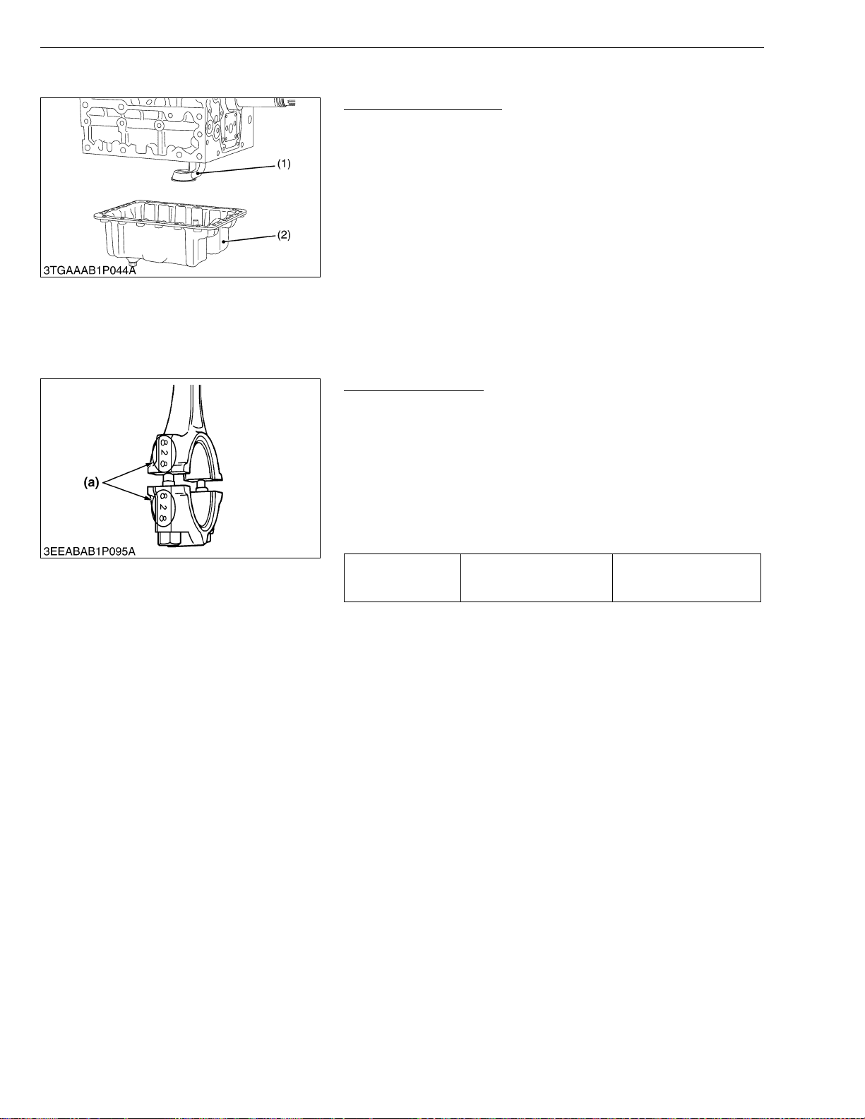
STα-30 · STα-35, WSM
KiSC issued 11, 2006 A
(C) Piston and Connecting Rod
ENGINE
Oil Pan and Oil Strainer
1. Remove the oil pan mounting screws.
2. Remove th e oil pan (2) by lightl y ta pping the rim of t he pan with
a wooden hammer.
3. Remove the oil strainer (1).
(When reassembling)
• After cleaning the oil strainer, check to see that the filter mesh in
clean, and install it.
• Visually check the O-ring, apply engine oil, and install it.
• Securely fit the O-ring to the oil strainer.
• Apply a liqui d gasket (Three B ond 1215 or equi valent) to the oi l
pan side of the oil pan gasket.
• To avoid uneven tighte ning, tighten oil pan mountin g screws in
diagonal order from the center.
(1) Oil Strainer (2) Oil Pan
W1025687
Connecting Rod Cap
1. Remove the conne cti ng rod caps .
(When reassembling)
• Align the marks (a) with each other. (Face the marks toward the
injection pump.)
• Apply engine oil to the connecting rod screws and lightly screw it
in by hand, then tighten it to the specified torque.
If the connecting rod scr ew wo n’t b e s crew ed i n s moo thly, c lean
the threads.
If the connecting rod screw is still hard to screw in, replace it.
Tightening torque Connecting rod screw
44.1 to 49.0 N·m
4.5 to 5.0 kgf·m
32.5 to 36.2 ft-lbs
(a) Mark
W1025878
1-S28
Page 91
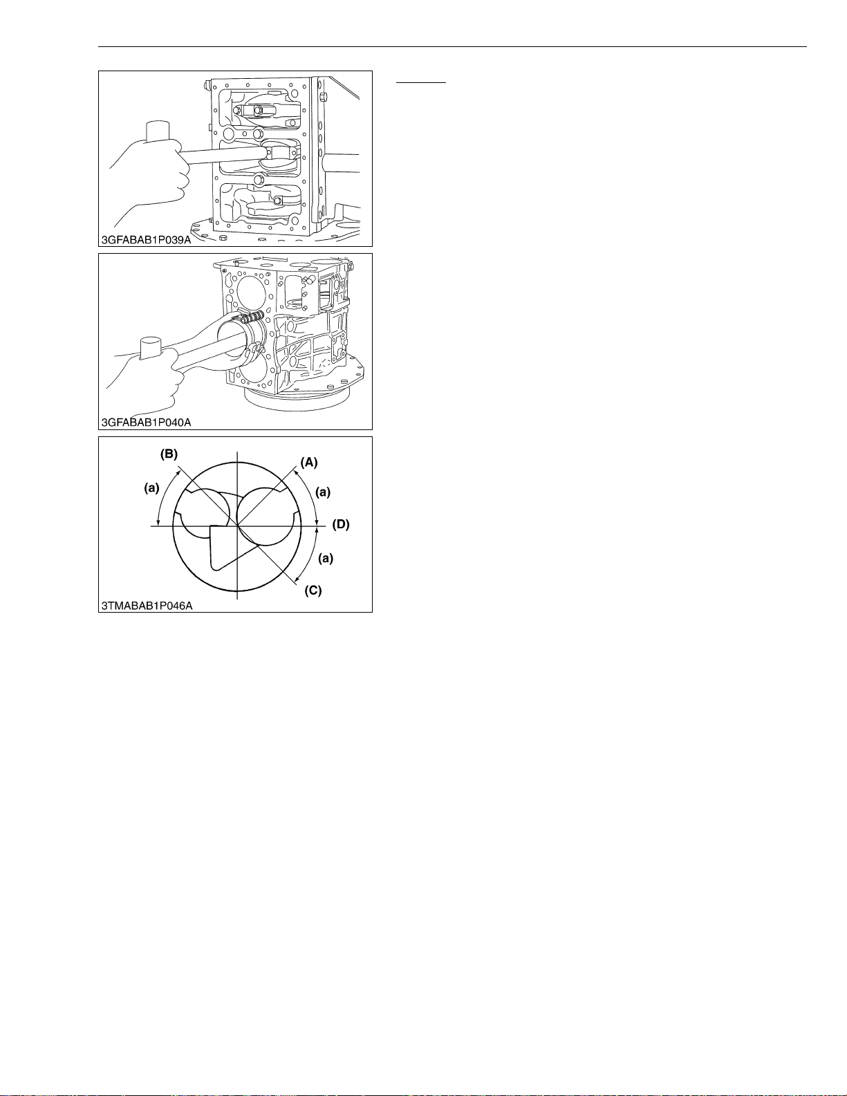
STα-30 · STα-35, WSM
IMPORTANT■
KiSC issued 11, 2006 A
ENGINE
Pistons
1. Turn the flywheel and bring the piston to top dead center.
2. Draw out the piston up ward by ligh tly tappin g it from the bo ttom
of the crankcase with the grip of a hammer.
3. Draw out the other piston in the same method as above.
(When reassembling)
• Before inserting piston into the cylinder, apply enough engine oil
to the piston.
• When inserting the pis ton into the cylinde r, f ace the mark on the
connecting rod to the injection pump.
• Do not change the combination of cylinder and piston. Make
sure of the position of each piston by marking. For example,
mark “1” on the No. 1 piston.
• Place the piston rings with their gaps at 0.79 rad. (45 °) from
the piston pin’s direction as shown in the figure.
• Carefully insert the pistons using a piston ring compressor.
• When inserting the piston in place, be careful not to get the
molybdenum disulfide coating torn off its skirt. This coating
is useful in minimizing the cle ar ance w ith th e cy linder lin er .
Just after the piston p in h as been pre ss- fit ted , in p ar ticu lar ,
the piston is still hot and the coating is easy to peel off. Wait
until the piston cools down.
(A) Top Ring Gap
(B) Second Ring Gap
(C) Oil Ring Gap
(D) Piston Pin Hole
(a) 0.79 rad. (45 °)
W1026141
1-S29
Page 92
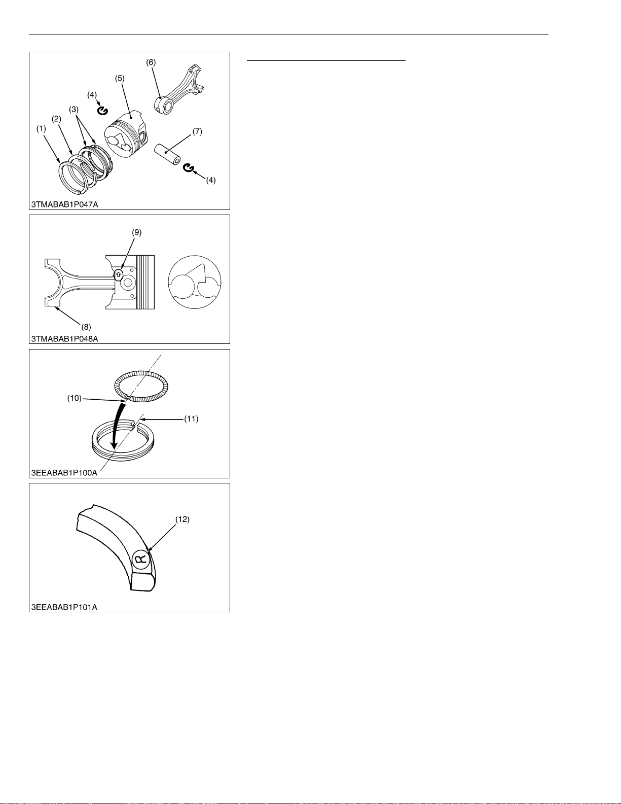
STα-30 · STα-35, WSM
NOTE■
KiSC issued 11, 2006 A
ENGINE
Piston Ring and Connecting Rod
1. Remove the piston rings using a piston ring tool (Code No.
07909-32121).
2. Remove the piston pin ( 7), and se parate the conn ecting rod (6)
from the piston (5).
(When reassembling)
• When installing the ring, assemble the rings so that the
manufacturer’s mark (12) near the gap faces the top of the piston.
• When installi ng the oil ring o nto the piston, plac e the expander
joint (10) on the opposite side of the oil ring gap (11).
• Apply engine oil to the piston pin.
• When installing the connecting rod to the piston, immerse the
piston in 80 °C (17 6 °F) oil for 10 to 15 mi nutes and insert the
piston pin to the piston.
• Assemble the piston to the connecting rod with the ↑ mark
(9) and the connecting rod mark (8) facing th e opposite side.
• Mark the same number on the connecting rod and the piston
so as not to change the combination.
(1) Top Ring
(2) Second Ring
(3) Oil Ring
(4) Piston Pin Snap Ring
(5) Piston
(6) Connecting Rod
(7) Piston Pin
(8) Mark
(9) Casting Ma rk
(10) Expander Joint
(11) Oil Ring Gap
(12) Manufact urer’s Mark
W1026376
1-S30
Page 93
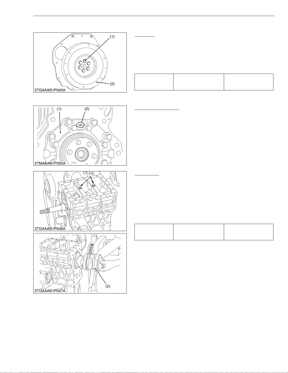
STα-30 · STα-35, WSM
KiSC issued 11, 2006 A
(D) Crankshaft
ENGINE
Flywheel
1. Lock the flywheel not to turn using the flywheel stopper.
2. Remove the flywheel screws (1) and flywheel (2).
(When reassembling)
• Apply engine oil to the flywheel screws.
• Check to see that there are no metal particles left on the flywheel
mounting surfaces.
98.0 to 107.8 N·m
Tightening torque Flywheel screws
(1) Flywheel Screw (2) Flywheel
10.0 to 11.0 kgf·m
72.3 to 79.5 ft-lbs
W1026863
Bearing Case Cover
1. Remove the bearing case cover mounting screws.
2. Remove the bearing case cover (1).
(When reassembling)
• Apply grease the oil seal lip, be careful not to peel the lip off.
• Install the bearing case cover (1) to position the casting mark
“UP” (2) on it upward.
• Tighten the bearing case cover mounting screws with even force
on the diagonal line.
(1) Bearing Case Cover (2) Casting Mark
W1027062
Crankshaft
1. Remove the main bearing case screws 2 (1).
2. Pull out the cran kshaft asse mbly (2), tak ing care no t to damage
the crankshaft bearing 1.
(When reassembling)
• Apply oil to the main bearing case screws 2.
• Clean the oil passage of the crankshaft with compressed air.
• Install the crankshaft assembly (2), aligning the screw hole of
main bearing case with the screw hole of crankcase.
68.6 to 73.5 N·m
7.0 to 7.5 kgf·m
50.6 to 54.2 ft-lbs
Tightening torque
Main bearing case screws
2
(1) Main Bearing Case Screw 2 (2) Crankshaft Assembly
W1027231
1-S31
Page 94
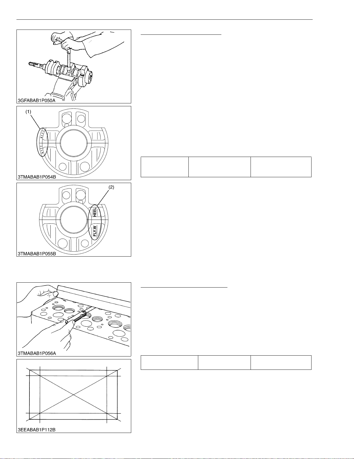
STα-30 · STα-35, WSM
IMPORTANT■
KiSC issued 11, 2006 A
ENGINE
Main Bearing Case Assembly
1. Remove the two main bearing case sc rews 1, and remove the
main bearing case assembly being careful with thrust bearing
and crankshaft bearing 2.
2. Remove the main bearing case 1, 2 as above.
(When reassembling)
• Clean the oil passage in the main bearing case.
• Apply clean engine oil on the bearings.
• Install the main bearing case assemblies in the original positions.
Since diameters of main bearing cases vary, install them in order
of makings (A, B) from the gear case side.
• Match the alignment numbers (1) and mark (2) on the main
bearing case.
• When installi ng the main bearing case 1 a nd 2, face the mark
“FLYWHEEL” to the flywheel.
• Install the thrust bearing with its oil groove facing outward.
• Confirm that the main bearing case moves smoothly after
tightening the main bearing case screw 1 to the specified torque.
46.1 to 50.9 N·m
Tightening torque Main bearing case screw 1
(1) Alignment Number (2) Alignment Mark
4.7 to 5.2 kgf·m
34.0 to 37.6 ft-lbs
W1027366
(3) Servicing
(A) Cylinder Head and Valves
Cylinder Head Surface Flatness
1. Clean the cylinder head surface.
2. Place a str aightedge on the cylind er head’s four sides and two
diagonal as shown in the figure.
3. Measure the clearance with a feeler gauge.
4. If the measurement ex ceeds the all owable limit, co rrect it with a
surface grinder.
• Do not place the straightedge on the combustion chamber.
• Be sure to check the valve recessing after correcting.
Cylinder head surface
flatness
Factory spec.
0.05 mm / 500 mm
0.0020 in. / 19.69 in.
W1027737
1-S32
Page 95
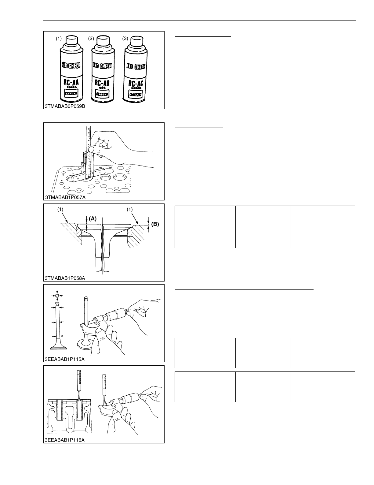
STα-30 · STα-35, WSM
KiSC issued 11, 2006 A
ENGINE
Cylinder Head Flaw
1. Prepare an air spray red check (Code No. 07909-31371).
2. Clean the surface of the cylinder head with detergent (2).
3. Spray the cylinde r head surfac e with the read p ermeative liq uid
(1). Leave it five to ten minutes after spraying.
4. Wash away the read permeative liquid on the cylinder head
surface with the detergent (2).
5. Spray the cylinder head surface with white developer (3).
6. If flawed, it can be identified as red marks.
(1) Red Permeative Liquid
(2) Detergent
(3) White Developer
W1076542
Valve Recessing
1. Clean the cylinder head surface, valve face and valve seat.
2. Insert the valve into the valve guide.
3. Measure the valve recessing with a depth gauge.
4. If the measurement exceeds the allowable limit, replace the
valve.
5. If it still exceeds the allowable limit after replacing the valve,
correct the valve seat face of the cylinder head with a valve seat
cutter (Code No. 07909-33102) or valve seat grinder.
6. Then, correct the cylinder head surface with a surface grinder, or
replace the cylinder head.
0.05 (protrusion) to
Factory spec.
Valve recessing
Allowable limit
0.15 (recessing) mm
0.0020 (protrusion) to
0.0059 (recessing) in.
0.40 (recessing) mm
0.0157 (recessing) in.
(1) Cylinder Head Surface (A) Recessing
(B) Protrusion
W1076880
Clearance between Valve Stem and Valve Guide
1. Remove carbon from the valve guide section.
2. Measure the valve stem O.D. with an outside micrometer.
3. Measure the valve guide I.D. with a small hole gauge, and
calculate the clearance .
4. If the clearance e xceeds the allowa ble limit, rep lace the valv es.
If it still exceeds the allowable limit, replace the valve guide.
Clearance between
valve stem and guide
Valve stem O.D. Factory spec.
Valve guide I.D. Factory spec.
Factory spec.
Allowable limit
0.040 to 0.070 mm
0.00157 to 0.00276 in.
0.1 mm
0.0039 in.
7.960 to 7.975 mm
0.31339 to 0.314398 in.
8.015 to 8.030 mm
0.31555 to 0.31614 in.
W1077495
1-S33
Page 96
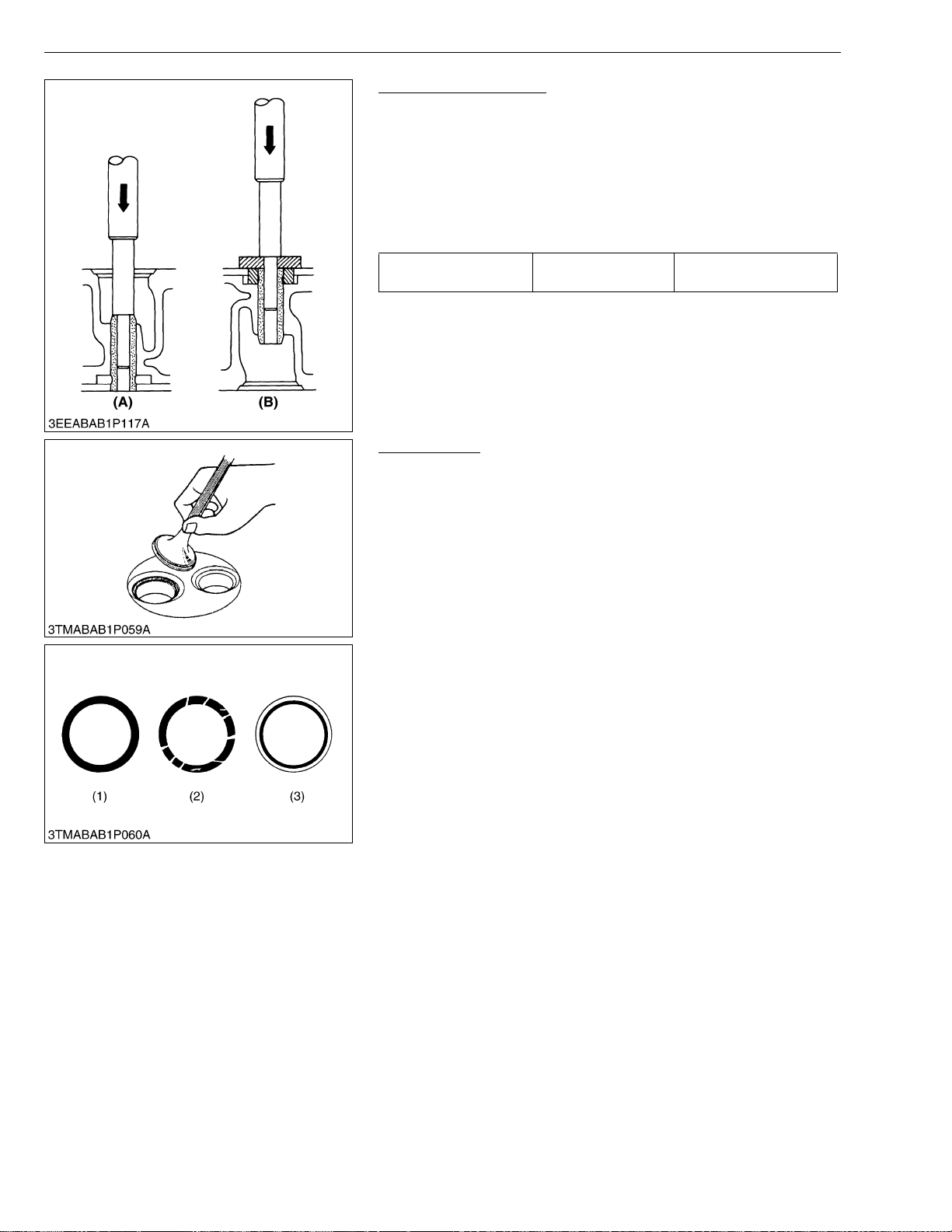
STα-30 · STα-35, WSM
IMPORTANT■
KiSC issued 11, 2006 A
ENGINE
Replacing Valve Guide
(When removing)
1. Press out the used valve guide using a valve guide replacing tool.
(When installing)
1. Clean a new valve guide and valve guide bore, and apply engine
oil to them.
2. Press in a new valve guide using a valve guide replacing too.
3. Ream precisely the I.D. of the valve guide to the specified
dimension.
Valve guide I.D.
(Intake and exhaust)
Factory spec.
8.015 to 8.030 mm
0.31555 to 0.31614 in.
• Do not hit the valve guide with a hammer during
replacement.
(A) When Removing (B) When Installing
W1027889
Valve Seating
1. Coat the valve face lightly with prussian blue and put the valve on
its seat to check the contact.
2. If the valve does not seat all the way around the valve seat or the
valve contact is less than 70 %, correct the valve seating as
follows.
3. If the valve conta ct does not comply with the reference value,
replace the valve or correct the contact of valve seating.
(1) Correct
(2) Incorrect
(3) Incorrect
W1028219
1-S34
Page 97
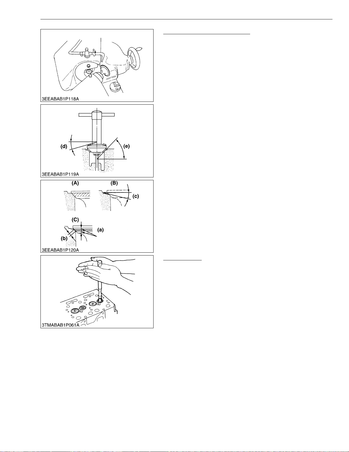
STα-30 · STα-35, WSM
NOTE■
IMPORTANT■
KiSC issued 11, 2006 A
ENGINE
Correcting Valve and Valve Seat
• Before correcting t he valve and seat , check the valve s tem
and the I.D. of valve guide section, and repair them if
necessary.
• After correcting the valve seat, be sure to check the valve
recessing.
1) Correcting Valve
1. Correct the valve with a valve refacer.
2) Correcting Valve Seat
1. Slightly correct the s eat surface with a 1.047 rad. (60 °) (intake
valve) or 0.785 r ad. ( 45 ° ) ( exh aus t v al ve) se at cut t er ( Cod e No .
07909-33102).
2. Resurface the se at surface with a 0.523 rad. (30 ° ) valve seat
cutter to intake valve seat and with a 0.262 rad. (15 °) valve seat
cutter to exhaust valve seat so that the width is close to specified
valve seat width (2.12 mm, 0.0835 in.)
3. After resurfacing the seat, inspect for even valve seating, apply a
thin film of compound between the valve face and valve seat, and
fit them with valve lapping tool.
4. Check the va lve seating with p russian blue. The valve seating
surface should show good contact all the way around.
(a) Identical Dimensions
(b) Valve Seat Width
(c) 0.523 rad. (30 °) or 0.262 rad. (15 °)
(d) 0.262 rad. (15 °) or 0.523 rad. (30 °)
(e) 0.785 rad. (45 °) or 1.047 rad. (60 °)
(A) Check Correct
(B) Correct Seat Width
(C) Check Contact
W1028350
Valve Lapping
1. Apply compound evenly to the valve lapping surface.
2. Insert the valve into t he valve gui de. Lap the val ve onto its sea t
with a valve flapper or screwdriver.
3. After lapping th e v al ve , wa sh th e c om pou nd away and apply oil,
then repeat valve lapping with oil.
4. Apply prussian bl ue to the contact surface to che ck the seated
rate. If it is less than 70 %, repeat valve lapping again.
• When valve lapping is performed, be sure to check the valve
recessing and adjust the valve clearance after assembling
the valve.
W1028814
1-S35
Page 98
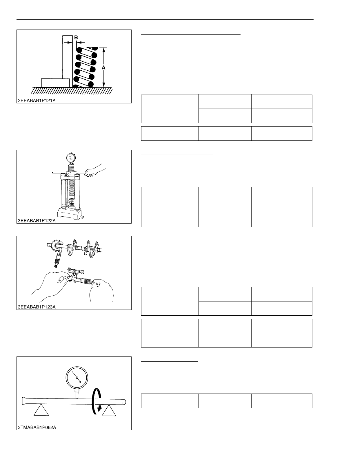
STα-30 · STα-35, WSM
KiSC issued 11, 2006 A
ENGINE
Free Length and Tilt of Valve Spring
1. Measure the free length (A) of valve spring with vernier calipers.
If the measurement is less than the allowable limit, replace it.
2. Put the val ve spring on a surface plate, p lace a square on the
side of the valve spring.
3. Check to see if the entire side is in contact with the square.
Rotate the valve spring and measure the maximum tilt (B).
Check the entire surface of the valve spring for scratches.
If there is any defect, replace it.
Factory spec.
Free length (A)
Allowable limit
41.7 to 42.2 mm
1.6417 to 1.6614 in.
41.2 mm
1.6220 in.
Tilt (B) Allowable limit
1.0 mm
0.039 in.
W1028935
Valve Spring Setting Load
1. Place the valve spring on a tester and com press it to the same
length it is actually compressed in the engine.
2. Read the compression load on the gauge.
3. If the measurement is less than the allowable limit, replace it.
117.6 N / 35 mm
Factory spec.
Setting load /
Setting length
Allowable limit
12.0 kgf / 35 mm
26.4 lbs / 1.3780 in.
100.0 N / 35 mm
10.2 kgf / 35 mm
22.5 lbs / 1.3780 in.
W1078436
Oil Clearance between Rocker Arm and Rocker Arm Shaft
1. Measure the rocker arm shaft O.D. with an outside micrometer.
2. Measure the rocker arm I.D. with an inside micrometer, and then
calculate the oil clearance.
3. If the oil clearance exceeds the allowable limit, replace the rocker
arm and measure the oil clearance again. If it st ill exceeds the
allowable limit, replace also the rocker arm shaft.
Oil clearance between
rocker arm and rocker
arm shaft
Factory spec.
Allowable limit
0.016 to 0.045 mm
0.00063 to 0.00177 in.
0.10 mm
0.0039 in.
Rocker arm shaft O.D. Factory spec.
Rocker arm I.D. F actory spec.
13.973 to 13.984 mm
0.55012 to 0.55055 in.
14.000 to 14.018 mm
0.55118 to 0.55189 in.
W1029150
Push Rod Alignment
1. Place the push rod on V blocks.
2. Measure the push rod align men t.
3. If the measurement exceeds the allowable limit, replace the push
rod.
Push rod alignment Allowable limit
0.25 mm
0.0098 in.
W1029290
1-S36
Page 99
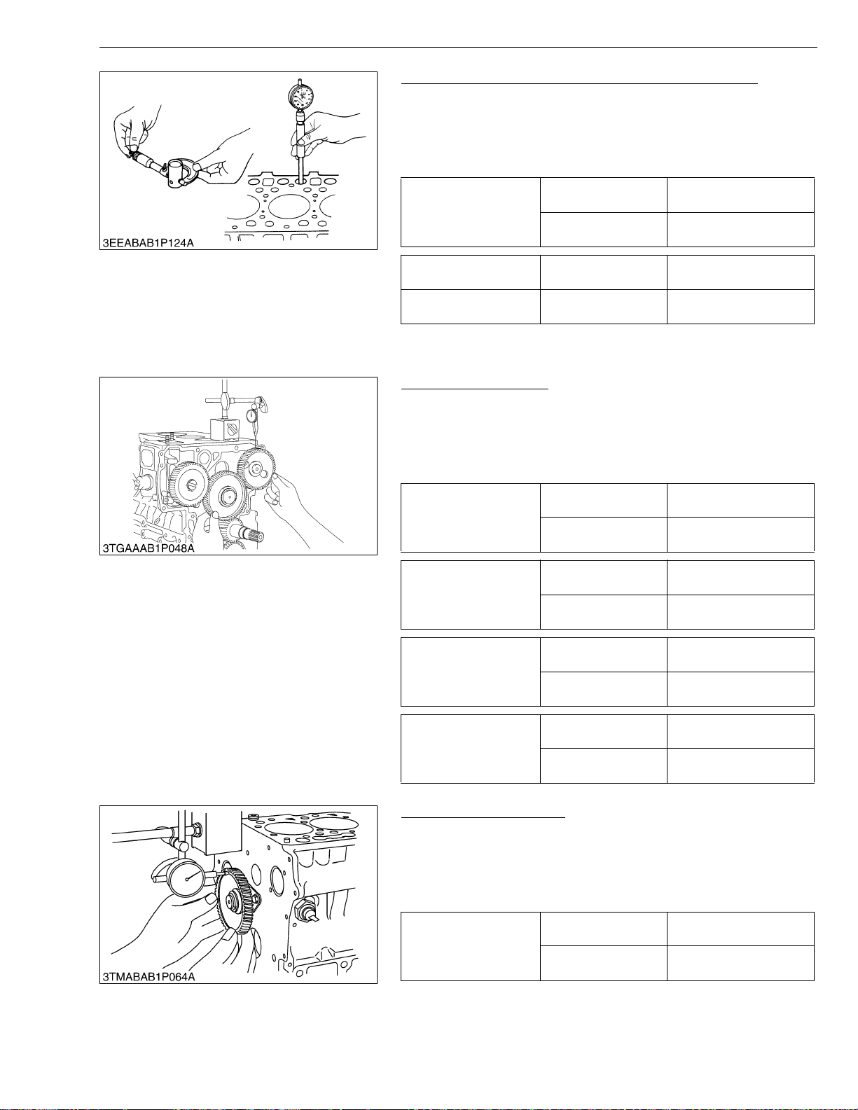
STα-30 · STα-35, WSM
KiSC issued 11, 2006 A
ENGINE
Oil Clearance between Tappet and Tappet Guide Bore
1. Measure the tappet O.D. with an outside micrometer.
2. Measure the I.D. of the tappet guide bore wit h a cy l inder ga uge ,
and calculate the oil clearance.
3. If the oil clearance ex ceeds the allowable limit or the ta ppet is
damaged, replace the tappet.
Oil Clearance between
tappet and tappet guide
bore
Factory spec.
Allowable limit
0.020 to 0.062 mm
0.00079 to 0.00244 in.
0.07 mm
0.0028 in.
Tappet O.D. Factory spec.
Tappet guide bore I.D. Factory spec.
(B) Timing Gears, Camshaft and Fuel Camshaft
Timing Gear Backlash
1. Set a dial indicator (lever type) with its tip on the gear tooth.
2. Move the gear to measure the backlash, holding its mating gear.
3. If the backlash exceeds the allowable limit, check the oil
clearance of the shafts and the gear.
4. If the oil clearance is proper, replace the gear.
Backlash between idle
gear and crank gear
Backlash between idle
gear and cam gear
Backlash between idle
gear and injection pump
gear
Factory spec.
Allowable limit
Factory spec.
Allowable limit
Factory spec.
Allowable limit
23.959 to 23.980 mm
0.94327 to 0.94410 in.
24.000 to 24.021 mm
0.94488 to 0.94571 in.
W1029366
0.0415 to 0.1122 mm
0.00163 to 0.00442 in.
0.15 mm
0.0059 in.
0.0415 to 0.1154 mm
0.00163 to 0.00454 in.
0.15 mm
0.0059 in.
0.0415 to 0.1154 mm
0.00163 to 0.00454 in.
0.15 mm
0.0059 in.
0.0415 to 0.1090 mm
0.00163 to 0.00429 in.
0.15 mm
0.0059 in.
W1029564
Backlash between crank
gear and oil pump gear
Factory spec.
Allowable limit
Idle Gear Side Clearance
1. Set a dial indicator with its tip on the idle gear.
2. Measure the side c learance by m oving the idle gear to th e front
and rear.
3. If the measurement e xceeds the all owable limi t, replac e the idle
gear collar.
Factory spec.
Idle gear side clearance
Allowable limit
0.12 to 0.48 mm
0.0047 to 0.0189 in.
0.9 mm
0.0354 in.
W1029843
1-S37
Page 100
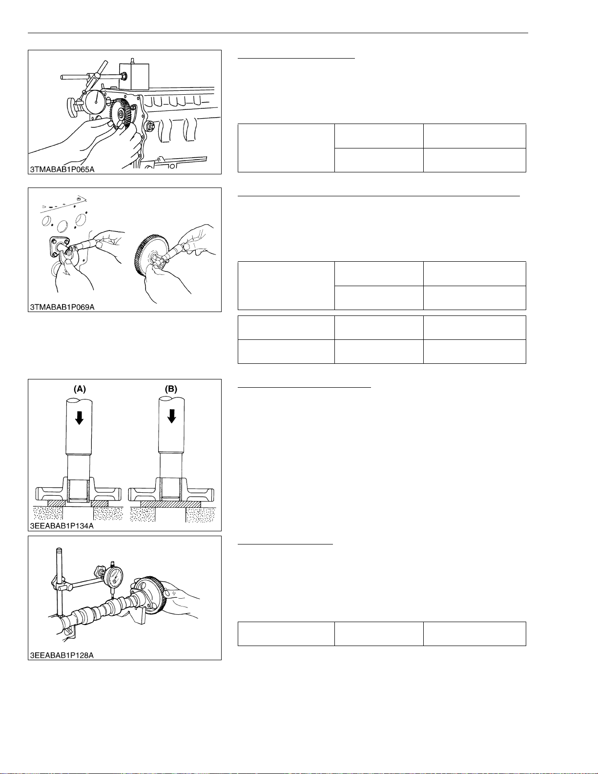
STα-30 · STα-35, WSM
KiSC issued 11, 2006 A
ENGINE
Camshaft Side Clearance
1. Set a dial indicator with its tip on the camshaft.
2. Measure the side clearance by moving the cam gear to the front
and rear.
3. If the measurement exceeds the allowable limit, replace the
camshaft stopper.
0.07 to 0.22 mm
0.0028 to 0.0087 in.
0.30 mm
0.0118 in.
W1030012
Camshaft side
clearance
Factory spec.
Allowable limit
Oil Clearance between Idle Gear Shaft and Idle Gear Bushing
1. Measure the idle gear shaft O.D. with an outside micrometer.
2. Measure the id le gear bushing I.D. with an inside micrometer,
and calculate the oil clearance.
3. If the oil clearance exceeds the allowable limit, replace the
bushing.
Clearance between idle
gear shaft and idle gear
bushing
Factory spec.
Allowable limit
0.025 to 0.066 mm
0.0010 to 0.0026 in.
0.1 mm
0.0039 in.
Idle gear shaft O.D. Factory spec.
Idle gear bushing I.D. Factory spec.
37.959 to 37.975 mm
1.49445 to 1.49508 in.
38.000 to 38.025 mm
1.49606 to 1.49704 in.
W1030933
Replacing Idle Gear Bushing
(A) (When removing)
1. Using an idle gear bushing replacing tool, press out the used
bushing.
(B) (When installing)
1. Clean a new idle gear bushing and idle gear bore, and apply
engine oil to them.
2. Using an idle gear bushing replacing tool, press in a new bushing
(service parts) to the specified dimension. (See figure.)
W1031083
Camshaft Alignment
1. Support the camsha ft with V b locks on th e surfa ce plate at both
end journals.
2. Set a dial indicator with its tip on the intermediate journal.
3. Measure the cams haft ali gn men t.
4. If the measurement exceeds the allowable limit, replace the
camshaft.
Camshaft alignment Allowable limit
0.01 mm
0.0004 in.
W1031413
1-S38
 Loading...