

Kubota D1803-CR-E4, D1803-CR-TE4, D1803-CR-TIE4, V2403-CR-TE4, V2403-CR-TE4BG Workshop Manual
...Page 1

WORKSHOP MANUAL
KiSC issued 12, 2018 A
DIESEL ENGINE
D1803-CR-E4,D1803-CR-TE4,
D1803-CR-TIE4,V2403-CR-E4,
V2403-CR-TE4,
V2403-CR-TE4BG,
V2403-CR-TIE4
Page 2

TO THE READER
KiSC issued 12, 2018 A
This workshop manual provides safety information for service activity, general information such as specifications and
dimensions of the machine, mechanisms and structure descriptions of the machine, and service procedures.
Safety
This section contains safety service descriptions and safety label information.
General
This section contains general instructions, tightening torques, general machine information and special tools.
Maintenance
This section contains information for the recommended oil and general maintenance procedures.
Each section basically consists of mechanism and servicing.
Mechanism
part
Mechanism
or component parts. This part should become prehended before proceeding with troubleshooting, disassembling,
assembling, and servicing works.
Servicing
Servicing part contains information and procedures for maintenance, troubleshooting and repair works. The reader
should follow these instructions in order to satisfy any servicing work safely, correctly and quickly.
In this WSM, service specifications and service limits are defined as followings.
Service specifications:
Specification which corresponds to new machine's ex-factory. It is based on quality standard, drawings, or actual
measurements conducted by Kubota. This value is used to determine whether there is a problem with the machine in
the event of a troubleshooting. However, it is necessary to consider degradation due to wear, based on the operating
time of the machine, application or maintenance condition.
Service limits:
Service limit is a value corresponding to the recommended performance limit by taking long term-use wear into
account. When the service limit is reached, the machine is required to have proper repair, overhaul or replacement in
order to keep safe and adequate performance.
All of the illustrations, photographs, specifications, and other information in this manual were created based on the
latest model at the time of publication.
The parts names used in this manual are unified into names representing the functions of the parts. Therefore, it does
not necessarily correspond to the names used in other materials (parts list, operators manual etc.) and the name on
the label / identification plates on the product.
Kubota reserves the right to change all information at any time without notice.
contains information and explanations for the structure, functions, and specifications of the machine
© KUBOTA Corporation
February 2013
Page 3

RECORD OF REVISIONS
D1803-CR-E4,D1803-CR-TE4,D1803-CR-TIE4,V2403-CR-E4,V2403-CR-TE4,V2403-CR-TE4BG,V2403-CR-TIE4
i
KiSC issued 12, 2018 A
Main revised contents and corrective measures are described in a table.
Find the main revised point and corrective measure through the reference page.
Last digit
of the Code
No.
1 2013.07 Rail pressure sensor
2 2013.12 Thermostat
3 2014.06 Oil separator
4 2014.09 Oil separator
5 2014.11 D1803-CR-TIE4
6 2017.04 SCV Added the information about disassembling and assembling. 4-124
Month of
Revision
Part name Main revised point and corrective measure
EGR valve lift sensor
Common rail and injection
pipes
alve guide
V
Rail
Diesel particulate filter
(DPF)
Air cleaner and others
Crankshaft position sensor
Fuel camshaft
Pistons
Flywheel
Main bearing case assembly
Positive crankcase ventilation (PCV) valve
Starter
Alternator
Glow plug
Pressure limiter valve
V2403-CR-TE4BG
V2403-CR-TIE4
Correction point
• 2. SPECIFICA
• 3. PERFORMANCE CURVES
• 4. MAINTENANCE CHECK LIST
– Cleaning water jacket and radiator interior
– Changing radiator coolant (L.L.C.)
• Mechanism
– Rail pressure sensor
– EGR valve lift sensor
• Servicing
– Adjusting valve clearance
– Common rail and injection pipes
– Replacing valve guide
– Measuring angular deviation between crankshaft TDC
and crankshaft position sensor detected TDC
Correction point
• 2. SPECIFICATIONS
• Model name and engine serial number
• Checking valve clearance
• Judging reuse of DPF filter comp after cleaning (Cleaning
contractor)
• Checking DPF differential pressure pipes and hoses
• Thermostat
• Rail
• Function of diesel particulate filter (DPF)
• TROUBLESHOOTING
• Adjusting valve clearance
• Disassembling and assembling
– Air cleaner and others
– Filter comp (DPF) (If necessary)
– Crankshaft position sensor
– Fuel camshaft
– Pistons
– Flywheel
– Main bearing case assembly
Correction point
• MAINTENANCE CHECK LIST
•
Check and maintenance
– Replacing oil separator element
– Checking positive crankcase ventilation (PCV) valve
• Checking and servicing
– Checking starter motor
– Checking magnetic switch of starter
– Checking magnetic switch continuity
– Checking alternator on unit
– Checking glow plug continuity
Correction the picture
Correction the information
Added the information of V2403-CR-TE4BG
Added the model about D1803-CR-TIE4 and V2403-CR-TIE4
These models are equipped DOC only instead of DPF.
TIONS
Reference
page
2-10
2-14
3-1
3-13
3-28
4-24
4-98
4-112
2-10
3-16
3-23
4-87
3-1
3-19
3-19
4-103
4-104
4-105
4-105
4-106
4-6
-
4-148
(Continued)
Page 4

Last digit
ii
D1803-CR-E4,D1803-CR-TE4,D1803-CR-TIE4,V2403-CR-E4,V2403-CR-TE4,V2403-CR-TE4BG,V2403-CR-TIE4
KiSC issued 12, 2018 A
of the Code
No.
7 2018.12 Mechanism
Month of
Revision
Part name Main revised point and corrective measure
Servicing
Added the information about all mechanism section.
Added the follow information about checking and adjusting.
• Checking injector
•
Checking suction control valve (SCV)
• Checking sensors
• Adjusting air gap between crank/camshaft position sensor
and flywheel/pulsar gear
Separate disassembling and assembling
Added follow servicing information.
• Replacing injector
• Replacing engine ECU
• Replacing DPF
Change notification about fan drive pulley mounting nut tightening
torque
Reference
page
4-96
4-107
4-107
4-114
4-115
4-191
4-193
4-196
Page 5

CONTENTS
D1803-CR-E4,D1803-CR-TE4,D1803-CR-TIE4,V2403-CR-E4,V2403-CR-TE4,V2403-CR-TE4BG,V2403-CR-TIE4
iii
KiSC issued 12, 2018 A
1. SAFETY
SAFETY FIRST
1.
Working precautions.................................................................................................................................1-1
2. Preparing for emergencies .......................................................................................................................1-1
3. Working cautions ...................................................................................................................................... 1-2
4. Starting the machine safely ......................................................................................................................1-3
5. Preventing fires......................................................................................................................................... 1-3
6. Preventing acid burns...............................................................................................................................1-4
7. Avoiding high pressure fluid......................................................................................................................1-4
8. Avoiding hot exhaust ................................................................................................................................1-4
9. Cleaning exhaust filter .............................................................................................................................. 1-4
2. GENERAL
GENERAL WORKING PRECAUTIONS ............................................................................................................2-1
1. Tightening bolts and nuts..........................................................................................................................2-1
2. Applying thread-locking fluid..................................................................................................................... 2-1
3. Installing circlips .......................................................................................................................................2-1
4. Handling liquid gasket ..............................................................................................................................2-2
5. Replacing O-rings.....................................................................................................................................2-2
6. Replacing oil seals.................................................................................................................................... 2-2
7. Handling the battery .................................................................................................................................2-3
8. Handling electrical wiring..........................................................................................................................2-3
9. Handling fuses..........................................................................................................................................2-4
10. Handling connectors...............................................................................................................................2-5
11. Wiring color ............................................................................................................................................. 2-6
12. Dispose fluids correctly........................................................................................................................... 2-6
GENERAL MACHINE INFORMATION ..............................................................................................................2-7
1. Engine identification .................................................................................................................................2-7
1.1 Engine model name and engine serial number................................................................................. 2-7
1.2 E4B engine........................................................................................................................................ 2-8
1.3 Cylinder number................................................................................................................................2-9
2. Muffler full assembly identification............................................................................................................2-9
2.1 Part number and serial number (DPF) .............................................................................................. 2-9
3. Specifications .........................................................................................................................................2-10
3.1 Specification for D1803-CR-E4, TE4 ..............................................................................................2-10
3.2 Specification for V2403-CR-E4, TE4............................................................................................... 2-11
3.3 Specification for D1803-CR-TIE4, V2403-CR-TIE4 ........................................................................2-12
3.4 Specification for V2403-CR-TE4BG................................................................................................2-13
4. Performance curves ...............................................................................................................................2-14
4.1 Performance curve for D1803-CR-E4 ............................................................................................. 2-14
4.2 Performance curve for D1803-CR-TE4...........................................................................................2-15
4.3 Performance curve for D1803-CR-TIE4..........................................................................................2-16
4.4 Performance curve for V2403-CR-E4 .............................................................................................2-17
4.5 Performance curve for V2403-CR-TE4 ........................................................................................... 2-18
4.6 Performance curve for V2403-CR-TIE4 .......................................................................................... 2-19
5. Dimensions.............................................................................................................................................2-20
5.1 Dimensions .....................................................................................................................................2-20
6. Wiring diagram .......................................................................................................................................2-21
6.1 Engine intermediate harness (Engine side harness) ......................................................................2-21
6.2 Injector intermediate harness (Engine side harness)......................................................................2-23
6.3 Engine ECU intermediate harness (OEM side harness).................................................................2-24
6.4 System wiring diagram for D1803-CR-E4, D1803-CR-TE4, V2403-CR-E4, V2403-CR-TE4,
6.5 System wiring diagram for D1803-CR-TIE4, V2403-CR-TIE4 ........................................................2-31
..................................................................................................................................................1-1
V2403-CR-TE4BG ..........................................................................................................................2-29
Page 6

SPECIAL TOOLS............................................................................................................................................. 2-33
iv
D1803-CR-E4,D1803-CR-TE4,D1803-CR-TIE4,V2403-CR-E4,V2403-CR-TE4,V2403-CR-TE4BG,V2403-CR-TIE4
KiSC issued 12, 2018 A
1. Diesel engine compression tester
2. Compression tester adapter K
..........................................................................................................2-33
................................................................................................................2-34
3. Oil pressure tester ..................................................................................................................................2-35
4. Valve guide replacing tool.......................................................................................................................2-35
5. Bushing replacing tools ..........................................................................................................................2-35
6. Flywheel stopper ....................................................................................................................................2-36
7. Crankshaft bearing 1 replacing tool........................................................................................................2-36
8. Auxiliary socket for fixing crankshaft sleeve ........................................................................................... 2-37
9. Injection top correction jig.......................................................................................................................2-38
10. Bearing case cover oil seal replacing tool ............................................................................................2-40
3. MAINTENANCE
MAINTENANCE CHECK LIST........................................................................................................................... 3-1
CHECK AND MAINTENANCE........................................................................................................................... 3-5
1. Daily check points..................................................................................................................................... 3-5
1.1 Checking engine oil level ..................................................................................................................3-5
1.2 Checking fuel level ............................................................................................................................ 3-6
1.3 Checking coolant level ......................................................................................................................3-6
1.4 Checking fan belt ..............................................................................................................................3-7
2. Check points of initial 50 hours................................................................................................................. 3-7
2.1 Changing engine oil ..........................................................................................................................3-7
2.2 Replacing oil filter cartridge...............................................................................................................3-8
3. Check point of every 50 hours..................................................................................................................3-8
3.1 Checking fuel hoses and clamp bands .............................................................................................3-8
3.2 Checking and draining water separator (Type 1) .............................................................................. 3-9
4. Check points of every 250 hours .............................................................................................................. 3-9
4.1 Cleaning air cleaner primary element ...............................................................................................3-9
4.2 Adjusting fan belt tension ................................................................................................................ 3-10
4.3 Checking radiator hose and clamp bands.......................................................................................3-10
4.4 Checking intake air line ................................................................................................................... 3-11
5. Check points of every 400 hours ............................................................................................................ 3-11
5.1 Changing engine oil ........................................................................................................................ 3-11
5.2 Replacing oil filter cartridge.............................................................................................................3-12
6. Check points of every 500 hours ............................................................................................................ 3-12
6.1 Replacing fuel filter cartridge........................................................................................................... 3-12
6.2 Cleaning water separator (Type 1).................................................................................................. 3-13
6.3 Replacing water separator filter (Type 2) ........................................................................................ 3-13
6.4 Cleaning water jacket and radiator interior...................................................................................... 3-13
6.5 Replacing fan belt ...........................................................................................................................3-15
7. Check point of every 1000 hours............................................................................................................3-16
7.1 Checking valve clearance ...............................................................................................................3-16
8. Check points of every 1500 hours .......................................................................................................... 3-17
8.1 Checking injector (with Diagmaster) ...............................................................................................3-17
8.2 Checking EGR cooler...................................................................................................................... 3-18
8.3 Replacing oil separator element...................................................................................................... 3-19
8.4 Checking positive crankcase ventilation (PCV) valve .....................................................................3-19
9. Check points of every 3000 hours .......................................................................................................... 3-20
9.1 Checking turbocharger....................................................................................................................3-20
9.2 Cleaning DPF..................................................................................................................................3-20
9.3 Judging reuse of DPF filter comp before cleaning (Service dealer)................................................3-22
9.4 Judging reuse of DPF filter comp after cleaning (Cleaning contractor)........................................... 3-23
9.5 Checking EGR system (with Diagmaster).......................................................................................3-24
10. Check points of every 1 year ................................................................................................................ 3-25
10.1 Replacing air cleaner element....................................................................................................... 3-25
10.2 Checking DPF differential pressure pipes and hoses ...................................................................3-25
10.3 Checking EGR piping....................................................................................................................3-26
10.4 Checking intake air line ................................................................................................................. 3-26
Page 7

10.5 Checking exhaust manifold ........................................................................................................... 3-27
D1803-CR-E4,D1803-CR-TE4,D1803-CR-TIE4,V2403-CR-E4,V2403-CR-TE4,V2403-CR-TE4BG,V2403-CR-TIE4
v
KiSC issued 12, 2018 A
10.6 Replacing water separator filter (T
......................................................................................3-27
ype 2)
11. Check points of every 2 years............................................................................................................... 3-27
11.1 Replacing fan belt..........................................................................................................................3-27
11.2 Replacing oil separator rubber hose.............................................................................................. 3-27
11.3 Replacing rubber hose of differential pressure sensor .................................................................. 3-28
11.4 Replacing intake hose (after air flow sensor) and intercooler hose...............................................3-28
11.5 Replacing EGR cooler hose ..........................................................................................................3-28
11.6 Replacing water hose .................................................................................................................... 3-28
11.7 Replacing lubricant hose ...............................................................................................................3-28
11.8 Changing radiator coolant .............................................................................................................3-28
11.9 Replacing radiator hose and clamp bands ....................................................................................3-30
11.10 Replacing fuel hose and clamps.................................................................................................. 3-31
11.11 Replacing intake air line............................................................................................................... 3-31
4. ENGINE
MECHANISM ..................................................................................................................................................... 4-1
1. General (Introduction)............................................................................................................................... 4-1
1.1 Feature of combustion (E-CDIS).......................................................................................................4-1
1.2 Structure of combustion (Center direct injection system (E-CDIS)) .................................................. 4-1
1.3 Flow of combustion (E-CDIS)............................................................................................................ 4-1
1.4 Control of combustion (E-CDIS)........................................................................................................ 4-2
2. Engine body.............................................................................................................................................. 4-3
2.1 Structure of engine body ................................................................................................................... 4-3
2.2 Feature of engine body .....................................................................................................................4-4
2.3 Crankcase ......................................................................................................................................... 4-4
2.3.1 Outline of crankcase ................................................................................................................. 4-4
2.3.2 Structure of crankcase..............................................................................................................4-4
2.3.3 Function of crankcase............................................................................................................... 4-4
2.3.4 Specification of crankcase ........................................................................................................ 4-4
2.4 Cylinder head .................................................................................................................................... 4-4
2.4.1 Outline of cylinder head ............................................................................................................ 4-4
2.4.2 Structure of cylinder head.........................................................................................................4-4
2.4.3 Function of cylinder head.......................................................................................................... 4-4
2.5 Cylinder head cover ..........................................................................................................................4-5
2.5.1 Outline of cylinder head cover ..................................................................................................4-5
2.5.2 Structure of cylinder head cover ............................................................................................... 4-5
2.5.3 Function of cylinder head cover................................................................................................4-5
2.6 Breather ............................................................................................................................................4-5
2.6.1 Outline of breather .................................................................................................................... 4-5
2.6.2 Structure of breather.................................................................................................................4-5
2.6.3 Function of breather.................................................................................................................. 4-5
2.7 Oil separator...................................................................................................................................... 4-5
2.7.1 Outline of oil separator.............................................................................................................. 4-5
2.7.2 Structure of oil separator ..........................................................................................................4-6
2.7.3 Function of oil separator ...........................................................................................................4-6
2.8 Piston ................................................................................................................................................4-6
2.8.1 Outline of piston........................................................................................................................4-6
2.8.2 Structure of piston..................................................................................................................... 4-6
2.8.3 Function of piston .....................................................................................................................4-6
2.8.4 Specification of piston...............................................................................................................4-6
2.9 Piston ring .........................................................................................................................................4-7
2.9.1 Outline of piston ring.................................................................................................................4-7
2.9.2 Structure of piston ring.............................................................................................................. 4-7
2.9.3 Function of piston ring ..............................................................................................................4-7
2.9.4 Specification of piston ring........................................................................................................4-7
2.10 Connecting rod................................................................................................................................4-7
2.10.1 Outline of connecting rod........................................................................................................4-7
Page 8

2.10.2 Structure of connecting rod..................................................................................................... 4-7
vi
D1803-CR-E4,D1803-CR-TE4,D1803-CR-TIE4,V2403-CR-E4,V2403-CR-TE4,V2403-CR-TE4BG,V2403-CR-TIE4
KiSC issued 12, 2018 A
2.10.3 Function of connecting rod
1 Crankshaft .......................................................................................................................................4-8
2.1
.....................................................................................................4-8
2.11.1 Outline of crankshaft ...............................................................................................................4-8
2.11.2 Structure of crankshaft ............................................................................................................ 4-8
2.11.3 Function of crankshaft.............................................................................................................4-8
2.11.4 Specification of crankshaft ......................................................................................................4-8
2.12 Main bearing case...........................................................................................................................4-8
2.12.1 Outline of main bearing case .................................................................................................. 4-8
2.12.2 Structure of main bearing case...............................................................................................4-8
2.12.3 Function of main bearing case................................................................................................ 4-8
2.13 Flywheel .......................................................................................................................................... 4-9
2.13.1 Outline of flywheel ..................................................................................................................4-9
2.13.2 Structure of flywheel ...............................................................................................................4-9
2.13.3 Function of flywheel ................................................................................................................ 4-9
2.13.4 Specification of flywheel .........................................................................................................4-9
2.14 Rocker arm...................................................................................................................................... 4-9
2.14.1 Outline of rocker arm ..............................................................................................................4-9
2.14.2 Structure of rocker arm ........................................................................................................... 4-9
2.14.3 Function of rocker arm..........................................................................................................4-10
2.15 Camshaft.......................................................................................................................................4-10
2.15.1 Outline of camshaft...............................................................................................................4-10
2.15.2 Structure of camshaft............................................................................................................ 4-10
2.15.3 Function of camshaft ............................................................................................................4-10
2.15.4 Specification of camshaft......................................................................................................4-10
2.16 Valve..............................................................................................................................................4-10
2.16.1 Outline of valve ..................................................................................................................... 4-10
2.16.2 Structure of valve..................................................................................................................4-10
2.16.3 Function of valve................................................................................................................... 4-10
2.16.4 Specification of valve ............................................................................................................ 4-10
2.17 Tappet ........................................................................................................................................... 4-11
2.17.1 Outline of tappet ................................................................................................................... 4-11
2.17.2 Structure of tappet ................................................................................................................4-11
2.17.3 Function of tappet ................................................................................................................. 4-11
2.18 Push rod........................................................................................................................................ 4-11
2.18.1 Outline of push rod ............................................................................................................... 4-11
2.18.2 Structure of push rod ............................................................................................................ 4-11
2.18.3 Function of push rod ............................................................................................................. 4-12
2.19 Timing gears..................................................................................................................................4-12
2.19.1 Outline of timing gears..........................................................................................................4-12
2.19.2 Structure of timing gears....................................................................................................... 4-12
2.19.3 Function of timing gears .......................................................................................................4-12
3. Fuel system ............................................................................................................................................4-13
3.1 Structure of common rail system (CRS) engine..............................................................................4-13
3.2 Feature of common rail system (CRS) engine ................................................................................ 4-14
3.3 Flow of common rail system (CRS) engine.....................................................................................4-15
3.4 Control of common rail system (CRS) engine.................................................................................4-17
3.5 Fuel tank .........................................................................................................................................4-17
3.5.1 Outline of fuel tank..................................................................................................................4-17
3.5.2 Structure of fuel tank............................................................................................................... 4-17
3.5.3 Function of fuel tank ...............................................................................................................4-17
3.5.4 Specification of fuel tank.........................................................................................................4-17
3.6 Water separator...............................................................................................................................4-17
3.6.1 Outline of water separator ......................................................................................................4-17
3.6.2 Structure of water separator (Type1)......................................................................................4-17
3.6.3 Structure of water separator (Type2)......................................................................................4-17
3.6.4 Function of water separator .................................................................................................... 4-18
3.6.5 Specification of water separator (Type2) ................................................................................ 4-18
Page 9

3.7 Electromagnetic fuel feed pump...................................................................................................... 4-18
D1803-CR-E4,D1803-CR-TE4,D1803-CR-TIE4,V2403-CR-E4,V2403-CR-TE4,V2403-CR-TE4BG,V2403-CR-TIE4
vii
KiSC issued 12, 2018 A
3.7.1 Outline of electromagnetic fuel feed pump
3.7.2 Structure of electromagnetic fuel feed pump
.............................................................................4-18
..........................................................................4-18
3.7.3 Function of electromagnetic fuel feed pump...........................................................................4-18
3.7.4 Specification of electromagnetic fuel feed pump ....................................................................4-18
3.8 Fuel feed pump ...............................................................................................................................4-19
3.8.1 Outline of fuel feed pump........................................................................................................ 4-19
3.8.2 Structure of fuel feed pump ....................................................................................................4-19
3.8.3 Function of fuel feed pump .....................................................................................................4-19
3.8.4 Specification of fuel feed pump............................................................................................... 4-19
3.9 Fuel filter .........................................................................................................................................4-20
3.9.1 Outline of fuel filter..................................................................................................................4-20
3.9.2 Structure of fuel filter............................................................................................................... 4-20
3.9.3 Function of fuel filter ...............................................................................................................4-20
3.9.4 Specification of fuel filter.........................................................................................................4-20
3.10 Supply pump .................................................................................................................................4-20
3.10.1 Outline of supply pump ......................................................................................................... 4-20
3.10.2 Structure of supply pump......................................................................................................4-20
3.10.3 Function of supply pump....................................................................................................... 4-21
3.10.4 Specification of supply pump ................................................................................................ 4-23
3.11 Injection pipe .................................................................................................................................4-23
3.11.1 Outline of injection pipe.........................................................................................................4-23
3.11.2 Structure of injection pipe...................................................................................................... 4-23
3.11.3 Function of injection pipe ......................................................................................................4-24
3.12 Rail assembly................................................................................................................................4-24
3.12.1 Outline of rail assembly ........................................................................................................4-24
3.12.2 Structure of rail assembly .....................................................................................................4-24
3.12.3 Function of rail assembly ...................................................................................................... 4-24
3.12.4 Specification of rail assembly ...............................................................................................4-25
3.13 Injector ..........................................................................................................................................4-26
3.13.1 Outline of injector..................................................................................................................4-26
3.13.2 Structure of injector............................................................................................................... 4-26
3.13.3 Function of injector ...............................................................................................................4-27
3.13.4 Specification of injector.........................................................................................................4-29
3.14 Overflow pipe ................................................................................................................................4-29
3.14.1 Outline of overflow pipe ........................................................................................................4-29
3.14.2 Structure of overflow pipe ..................................................................................................... 4-29
3.14.3 Function of overflow pipe......................................................................................................4-29
3.15 Check valve................................................................................................................................... 4-29
3.15.1 Outline of check valve........................................................................................................... 4-29
3.15.2 Structure of check valve .......................................................................................................4-29
3.15.3 Function of check valve ........................................................................................................4-29
3.15.4 Specification of check valve.................................................................................................. 4-29
3.16 Fuel cooler ....................................................................................................................................4-29
3.16.1 Outline of fuel cooler.............................................................................................................4-29
3.16.2 Structure of fuel cooler.......................................................................................................... 4-30
3.16.3 Function of fuel cooler ..........................................................................................................4-30
3.17 Engine ECU ..................................................................................................................................4-30
3.17.1 Outline of engine ECU .......................................................................................................... 4-30
3.17.2 Structure of engine ECU.......................................................................................................4-30
3.17.3 Function of engine ECU........................................................................................................ 4-30
3.17.4 Specification of engine ECU ................................................................................................. 4-30
3.18 Crankshaft position sensor............................................................................................................ 4-31
3.18.1 Outline of crankshaft position sensor.................................................................................... 4-31
3.18.2 Structure of crankshaft position sensor ................................................................................4-31
3.18.3 Function of crankshaft position sensor .................................................................................4-31
3.18.4 Specification of crankshaft position sensor........................................................................... 4-31
3.19 Camshaft position sensor.............................................................................................................. 4-32
Page 10

3.19.1 Outline of camshaft position sensor...................................................................................... 4-32
viii
D1803-CR-E4,D1803-CR-TE4,D1803-CR-TIE4,V2403-CR-E4,V2403-CR-TE4,V2403-CR-TE4BG,V2403-CR-TIE4
KiSC issued 12, 2018 A
3.19.2 Structure of camshaft position sensor
3.19.3 Function of camshaft position sensor
..................................................................................4-32
...................................................................................4-32
3.19.4 Specification of camshaft position sensor............................................................................. 4-32
3.20 Coolant temperature sensor.......................................................................................................... 4-33
3.20.1 Outline of coolant temperature sensor.................................................................................. 4-33
3.20.2 Structure of coolant temperature sensor ..............................................................................4-33
3.20.3 Function of coolant temperature sensor ...............................................................................4-33
3.20.4 Specification of coolant temperature sensor......................................................................... 4-33
3.21 Boost pressure sensor ..................................................................................................................4-34
3.21.1 Outline of boost pressure sensor..........................................................................................4-34
3.21.2 Structure of boost pressure sensor....................................................................................... 4-34
3.21.3 Function of boost pressure sensor .......................................................................................4-34
3.21.4 Specification of boost pressure sensor.................................................................................4-34
3.22 Atmosphere pressure sensor ........................................................................................................ 4-34
3.22.1 Outline of atmosphere pressure sensor................................................................................ 4-34
3.22.2 Structure of atmosphere pressure sensor ............................................................................4-34
3.22.3 Function of atmosphere pressure sensor .............................................................................4-34
3.23 Fuel camshaft................................................................................................................................ 4-35
3.23.1 Outline of fuel camshaft ........................................................................................................ 4-35
3.23.2 Structure of fuel camshaft.....................................................................................................4-35
3.23.3 Function of fuel camshaft...................................................................................................... 4-35
4. Intake and exhaust system.....................................................................................................................4-36
4.1 Structure of intake and exhaust system .......................................................................................... 4-36
4.2 Feature of intake and exhaust system ............................................................................................4-37
4.3 Flow of intake and exhaust system ................................................................................................. 4-38
4.4 Control of intake and exhaust system ............................................................................................. 4-40
4.5 Pre-cleaner...................................................................................................................................... 4-40
4.5.1 Outline of pre-cleaner .............................................................................................................4-40
4.5.2 Structure of pre-cleaner .......................................................................................................... 4-40
4.5.3 Function of pre-cleaner...........................................................................................................4-40
4.5.4 Specification of pre-cleaner ....................................................................................................4-40
4.6 Air cleaner ....................................................................................................................................... 4-40
4.6.1 Outline of air cleaner............................................................................................................... 4-40
4.6.2 Structure of air cleaner ...........................................................................................................4-40
4.6.3 Function of air cleaner ............................................................................................................4-40
4.6.4 Specification of air cleaner...................................................................................................... 4-40
4.7 Turbocharger................................................................................................................................... 4-40
4.7.1 Outline of turbocharger ........................................................................................................... 4-40
4.7.2 Structure of turbocharger........................................................................................................4-41
4.7.3 Function of turbocharger......................................................................................................... 4-41
4.7.4 Specification of turbocharger .................................................................................................. 4-41
4.8 Intercooler .......................................................................................................................................4-41
4.8.1 Outline of intercooler............................................................................................................... 4-41
4.8.2 Structure of intercooler ...........................................................................................................4-41
4.8.3 Function of intercooler ............................................................................................................4-41
4.8.4 Specification of intercooler...................................................................................................... 4-41
4.9 Glow plug ........................................................................................................................................4-42
4.9.1 Outline of glow plug ................................................................................................................4-42
4.9.2 Structure of glow plug ............................................................................................................. 4-42
4.9.3 Function of glow plug..............................................................................................................4-42
4.9.4 Specification of glow plug .......................................................................................................4-42
4.10 Intake manifold..............................................................................................................................4-42
4.10.1 Outline of intake manifold .....................................................................................................4-42
4.10.2 Structure of intake manifold .................................................................................................. 4-42
4.10.3 Function of intake manifold...................................................................................................4-42
4.11 Exhaust manifold ........................................................................................................................... 4-42
4.11.1 Outline of exhaust manifold................................................................................................... 4-42
Page 11

4.11.2 Structure of exhaust manifold ...............................................................................................4-42
D1803-CR-E4,D1803-CR-TE4,D1803-CR-TIE4,V2403-CR-E4,V2403-CR-TE4,V2403-CR-TE4BG,V2403-CR-TIE4
ix
KiSC issued 12, 2018 A
4.1
1.3 Function of exhaust manifold
................................................................................................4-43
5. Exhaust gas recirculation (EGR) system................................................................................................4-44
5.1 Structure of EGR system ................................................................................................................4-44
5.2 Feature of EGR system................................................................................................................... 4-45
5.3 Flow of EGR system........................................................................................................................4-46
5.4 Control of EGR system ...................................................................................................................4-47
5.5 EGR cooler...................................................................................................................................... 4-47
5.5.1 Outline of EGR cooler.............................................................................................................4-47
5.5.2 Structure of EGR cooler.......................................................................................................... 4-47
5.5.3 Function of EGR cooler ..........................................................................................................4-47
5.5.4 Specification of EGR cooler....................................................................................................4-47
5.6 EGR valve ....................................................................................................................................... 4-47
5.6.1 Outline of EGR valve ..............................................................................................................4-47
5.6.2 Structure of EGR valve ........................................................................................................... 4-48
5.6.3 Function of EGR valve............................................................................................................4-50
5.6.4 Specification of EGR valve .....................................................................................................4-50
5.7 Reed valve ......................................................................................................................................4-50
5.7.1 Outline of reed valve...............................................................................................................4-50
5.7.2 Structure of reed valve............................................................................................................ 4-50
5.7.3 Function of reed valve ............................................................................................................4-50
6. Lubricating system.................................................................................................................................. 4-51
6.1 Structure of lubricating system........................................................................................................4-51
6.2 Feature of lubricating system .......................................................................................................... 4-52
6.3 Flow of lubricating system...............................................................................................................4-53
6.4 Oil pan.............................................................................................................................................4-55
6.4.1 Outline of oil pan.....................................................................................................................4-55
6.4.2 Structure of oil pan.................................................................................................................. 4-55
6.4.3 Function of oil pan ..................................................................................................................4-55
6.4.4 Specification of oil pan............................................................................................................4-55
6.5 Oil strainer.......................................................................................................................................4-55
6.5.1 Outline of oil strainer...............................................................................................................4-55
6.5.2 Structure of oil strainer............................................................................................................ 4-55
6.5.3 Function of oil strainer ............................................................................................................4-55
6.5.4 Specification of oil strainer......................................................................................................4-55
6.6 Oil pump..........................................................................................................................................4-56
6.6.1 Outline of oil pump..................................................................................................................4-56
6.6.2 Structure of oil pump............................................................................................................... 4-56
6.6.3 Function of oil pump ...............................................................................................................4-56
6.6.4 Specification of oil pump.........................................................................................................4-56
6.7 Relief valve...................................................................................................................................... 4-56
6.7.1 Outline of relief valve ..............................................................................................................4-56
6.7.2 Structure of relief valve ........................................................................................................... 4-56
6.7.3 Function of relief valve............................................................................................................4-57
6.8 Oil filter ............................................................................................................................................ 4-57
6.8.1 Outline of oil filter .................................................................................................................... 4-57
6.8.2 Structure of oil filter.................................................................................................................4-57
6.8.3 Function of oil filter.................................................................................................................. 4-57
6.8.4 Specification of oil filter ........................................................................................................... 4-57
6.9 Oil cooler ......................................................................................................................................... 4-57
6.9.1 Outline of oil cooler ................................................................................................................. 4-57
6.9.2 Structure of oil cooler..............................................................................................................4-57
6.9.3 Function of oil cooler............................................................................................................... 4-58
6.9.4 Specification of oil cooler ........................................................................................................ 4-58
6.10 Oil pressure switch........................................................................................................................4-58
6.10.1 Outline of oil pressure switch................................................................................................4-58
6.10.2 Structure of oil pressure switch............................................................................................. 4-58
6.10.3 Function of oil pressure switch .............................................................................................4-58
Page 12

6.10.4 Specification of oil pressure switch.......................................................................................4-59
x
D1803-CR-E4,D1803-CR-TE4,D1803-CR-TIE4,V2403-CR-E4,V2403-CR-TE4,V2403-CR-TE4BG,V2403-CR-TIE4
KiSC issued 12, 2018 A
7. Cooling system
7.1 Structure of cooling system
.......................................................................................................................................4-60
.............................................................................................................4-60
7.2 Feature of cooling system ............................................................................................................... 4-61
7.3 Flow of cooling system (Bottom by-pass system) ........................................................................... 4-61
7.4 Control of cooling system (Bottom by-pass system) ....................................................................... 4-61
7.5 Water pump..................................................................................................................................... 4-61
7.5.1 Outline of water pump............................................................................................................. 4-61
7.5.2 Structure of water pump .........................................................................................................4-61
7.5.3 Function of water pump ..........................................................................................................4-62
7.6 Thermostat ...................................................................................................................................... 4-62
7.6.1 Outline of thermostat ..............................................................................................................4-62
7.6.2 Structure of thermostat ...........................................................................................................4-62
7.6.3 Function of thermostat ............................................................................................................ 4-62
7.6.4 Specification of thermostat .....................................................................................................4-62
7.7 Radiator........................................................................................................................................... 4-63
7.7.1 Outline of radiator ...................................................................................................................4-63
7.7.2 Structure of radiator ................................................................................................................ 4-63
7.7.3 Function of radiator.................................................................................................................4-63
7.7.4 Specification of radiator ..........................................................................................................4-63
7.8 Radiator cap....................................................................................................................................4-63
7.8.1 Outline of radiator cap ............................................................................................................4-63
7.8.2 Structure of radiator cap .........................................................................................................4-63
7.8.3 Function of radiator cap .......................................................................................................... 4-64
7.8.4 Specification of radiator cap ...................................................................................................4-64
7.9 Cooling fan ...................................................................................................................................... 4-64
7.9.1 Outline of cooling fan .............................................................................................................. 4-64
7.9.2 Structure of cooling fan...........................................................................................................4-64
7.9.3 Function of cooling fan............................................................................................................ 4-64
7.9.4 Specification of cooling fan ..................................................................................................... 4-64
7.10 Reserve tank ................................................................................................................................. 4-65
7.10.1 Outline of reserve tank.......................................................................................................... 4-65
7.10.2 Structure of reserve tank ......................................................................................................4-65
7.10.3 Function of reserve tank .......................................................................................................4-65
7.11 Fan belt..........................................................................................................................................4-65
7.11.1 Outline of fan belt .................................................................................................................. 4-65
7.11.2 Structure of fan belt...............................................................................................................4-65
7.11.3 Function of fan belt................................................................................................................4-65
8. Electrical system..................................................................................................................................... 4-66
8.1 Structure of electrical system .......................................................................................................... 4-66
8.2 Feature of electrical system ............................................................................................................4-67
8.3 Flow of electrical system ................................................................................................................. 4-68
8.4 Control of electrical system ............................................................................................................. 4-70
8.5 Battery.............................................................................................................................................4-70
8.5.1 Outline of battery ....................................................................................................................4-70
8.5.2 Structure of battery .................................................................................................................4-70
8.5.3 Function of battery .................................................................................................................. 4-70
8.5.4 Specification of battery ...........................................................................................................4-70
8.6 Key switch ....................................................................................................................................... 4-70
8.6.1 Outline of key switch...............................................................................................................4-70
8.6.2 Structure of key switch............................................................................................................ 4-70
8.6.3 Function of key switch ............................................................................................................4-71
8.6.4 Specification of key switch......................................................................................................4-71
8.7 Starter (Planetary gear reduction type) ........................................................................................... 4-71
8.7.1 Outline of starter (planetary gear reduction type) ...................................................................4-71
8.7.2 Structure of starter (planetary gear reduction type) ................................................................ 4-71
8.7.3 Function of starter (planetary gear reduction type).................................................................4-71
8.7.4 Specification of starter (planetary gear reduction type) ..........................................................4-72
Page 13

8.8 Alternator......................................................................................................................................... 4-72
D1803-CR-E4,D1803-CR-TE4,D1803-CR-TIE4,V2403-CR-E4,V2403-CR-TE4,V2403-CR-TE4BG,V2403-CR-TIE4
xi
KiSC issued 12, 2018 A
8.8.1 Outline of alternator
8.8.2 Structure of alternator
................................................................................................................4-72
.............................................................................................................4-72
8.8.3 Function of alternator..............................................................................................................4-72
8.8.4 Specification of alternator .......................................................................................................4-74
9. Aftertreatment system ............................................................................................................................4-75
9.1 Structure of diesel particulate filter (DPF) system...........................................................................4-75
9.2 Feature of diesel particulate filter (DPF) system ............................................................................. 4-75
9.3 Flow of diesel particulate filter (DPF) system..................................................................................4-75
9.4 Control of diesel particulate filter (DPF) system..............................................................................4-76
9.5 Structure of diesel oxidation catalyst (DOC) system.......................................................................4-78
9.6 Feature of diesel oxidation catalyst (DOC) system ......................................................................... 4-78
9.7 Flow of diesel oxidation catalyst (DOC) system..............................................................................4-78
9.8 Diesel oxidation catalyst (DOC) ......................................................................................................4-79
9.8.1 Outline of diesel oxidation catalyst (DOC) .............................................................................. 4-79
9.8.2 Structure of diesel oxidation catalyst (DOC)...........................................................................4-79
9.8.3 Function of diesel oxidation catalyst (DOC)............................................................................ 4-79
9.9 Diesel particulate filter (DPF) ..........................................................................................................4-79
9.9.1 Outline of diesel particulate filter (DPF) .................................................................................. 4-79
9.9.2 Structure of diesel particulate filter (DPF)...............................................................................4-79
9.9.3 Function of diesel particulate filter (DPF)................................................................................ 4-80
9.10 Air flow sensor............................................................................................................................... 4-80
9.10.1 Outline of air flow sensor ......................................................................................................4-80
9.10.2 Structure of air flow sensor ................................................................................................... 4-80
9.10.3 Function of air flow sensor....................................................................................................4-80
9.10.4 Specification of air flow sensor .............................................................................................4-81
9.11 Exhaust gas temperature sensor................................................................................................... 4-81
9.11.1 Outline of exhaust gas temperature sensor ..........................................................................4-81
9.11.2 Structure of exhaust gas temperature sensor ....................................................................... 4-81
9.11.3 Function of exhaust gas temperature sensor........................................................................4-82
9.11.4 Specification of exhaust gas temperature sensor .................................................................4-82
9.12 Differential pressure sensor ..........................................................................................................4-83
9.12.1 Outline of differential pressure sensor .................................................................................. 4-83
9.12.2 Structure of differential pressure sensor...............................................................................4-83
9.12.3 Function of differential pressure sensor................................................................................ 4-83
9.12.4 Specification of differential pressure sensor ......................................................................... 4-83
9.13 Intake throttle valve ....................................................................................................................... 4-84
9.13.1 Outline of intake throttle valve ..............................................................................................4-84
9.13.2 Structure of intake throttle valve ...........................................................................................4-84
9.13.3 Function of intake throttle valve ............................................................................................ 4-84
9.13.4 Specification of intake throttle valve .....................................................................................4-84
SERVICING .....................................................................................................................................................4-87
1. Troubleshooting......................................................................................................................................4-87
1.1 Troubleshooting for 03 series engine..............................................................................................4-87
2. Service specifications ............................................................................................................................. 4-91
2.1 Service specifications for engine..................................................................................................... 4-91
3. Tightening torques..................................................................................................................................4-96
3.1 Tightening torques of screws, bolts and nuts for general use.........................................................4-96
3.2 Tightening torques of screws, bolts and nuts for special use.......................................................... 4-96
4. Checking and adjusting ..........................................................................................................................4-98
4.1 Checking compression pressure of cylinder ...................................................................................4-98
4.2 Adjusting valve clearance ...............................................................................................................4-98
4.3 Checking engine oil pressure..........................................................................................................4-99
4.4 Checking fan belt tension..............................................................................................................4-100
4.5 Checking fan belt damage and wear............................................................................................. 4-100
4.6 Checking radiator cap air leakage................................................................................................. 4-100
4.7 Checking radiator water leakage................................................................................................... 4-101
4.8 Checking opening temperature of thermostat valve...................................................................... 4-101
Page 14

4.9 Checking battery voltage............................................................................................................... 4-102
xii
D1803-CR-E4,D1803-CR-TE4,D1803-CR-TIE4,V2403-CR-E4,V2403-CR-TE4,V2403-CR-TE4BG,V2403-CR-TIE4
KiSC issued 12, 2018 A
4.10 Checking battery specific gravity
.................................................................................................4-
102
4.11 Checking starter motor ................................................................................................................4-103
4.12 Checking magnetic switch of starter ...........................................................................................4-104
4.13 Checking magnetic switch continuity ..........................................................................................4-105
4.14 Checking alternator on unit .........................................................................................................4-105
4.15 Checking glow plug continuity.....................................................................................................4-106
4.16 Checking exhaust gas leakage of turbocharger turbine side ......................................................4-106
4.17 Checking air leakage of turbocharger compressor side..............................................................4-106
4.18 Checking radial clearance of turbocharger .................................................................................4-107
4.19 Checking injector......................................................................................................................... 4-107
4.20 Checking suction control valve (SCV).........................................................................................4-107
4.21 Checking rail pressure sensor..................................................................................................... 4-108
4.22 Checking boost pressure sensor................................................................................................. 4-108
4.23 Checking crankshaft position sensor ..........................................................................................4-109
4.24 Checking camshaft position sensor ............................................................................................4-109
4.25 Checking coolant temperature sensor ........................................................................................4-109
4.26 Checking EGR system ................................................................................................................ 4-110
4.27 Checking air flow sensor ............................................................................................................. 4-110
4.28 Checking exhaust gas temperature sensor................................................................................. 4-111
4.29 Selecting cylinder head gasket ................................................................................................... 4-111
4.30 Measuring angular deviation between crankshaft T.D.C. and crankshaft position sensor
detected T.D.C. ........................................................................................................................... 4-112
4.31 Adjusting air gap between crankshaft position sensor and flywheel ........................................... 4-114
4.32 Adjusting air gap between camshaft position sensor and pulsar gear ........................................ 4-115
5. Disassembling ......................................................................................................................................4-115
5.1 Draining engine oil ........................................................................................................................ 4-115
5.2 Draining coolant ............................................................................................................................4-115
5.3 Removing CRS intermediate harness........................................................................................... 4-116
5.4 Removing external components.................................................................................................... 4-116
5.5 Removing muffler full assembly .................................................................................................... 4-117
5.6 Disassembling DPF assembly ...................................................................................................... 4-118
5.7 Removing EGR cooler .................................................................................................................. 4-119
5.8 Removing turbocharger................................................................................................................. 4-119
5.9 Removing intake throttle valve ...................................................................................................... 4-120
5.10 Removing EGR valve..................................................................................................................4-120
5.11 Removing common rail................................................................................................................4-120
5.12 Removing sensors ......................................................................................................................4-121
5.13 Removing cylinder head cover....................................................................................................4-122
5.14 Removing glow plug....................................................................................................................4-122
5.15 Removing injector .......................................................................................................................4-122
5.16 Removing rocker arm assembly.................................................................................................. 4-123
5.17 Removing cylinder head.............................................................................................................. 4-123
5.18 Removing tappet ......................................................................................................................... 4-124
5.19 Removing valve........................................................................................................................... 4-124
5.20 Removing thermostat assembly..................................................................................................4-124
5.21 Removing suction control valve (SCV)........................................................................................ 4-124
5.22 Removing supply pump............................................................................................................... 4-125
5.23 Removing oil cooler..................................................................................................................... 4-125
5.24 Removing water pump ................................................................................................................4-126
5.25 Removing fan drive pulley...........................................................................................................4-126
5.26 Removing gear case cover .........................................................................................................4-126
5.27 Removing crankshaft oil slinger ..................................................................................................4-126
5.28 Removing idle gear .....................................................................................................................4-127
5.29 Removing fuel camshaft assembly .............................................................................................4-127
5.30 Removing camshaft with cam gear ............................................................................................. 4-128
5.31 Removing oil pump .....................................................................................................................4-128
5.32 Removing crank gear .................................................................................................................. 4-128
Page 15

5.33 Removing oil pan and oil strainer................................................................................................4-129
D1803-CR-E4,D1803-CR-TE4,D1803-CR-TIE4,V2403-CR-E4,V2403-CR-TE4,V2403-CR-TE4BG,V2403-CR-TIE4
xiii
KiSC issued 12, 2018 A
5.34 Removing piston
.........................................................................................................................4-
129
5.35 Removing piston ring ..................................................................................................................4-129
5.36 Disassembling piston assembly .................................................................................................. 4-130
5.37 Removing flywheel ...................................................................................................................... 4-130
5.38 Removing flywheel housing ........................................................................................................4-131
5.39 Removing bearing case cover..................................................................................................... 4-131
5.40 Removing crankshaft (for 3 cylinders)......................................................................................... 4-131
5.41 Removing crankshaft (for 4 cylinders)......................................................................................... 4-132
5.42 Removing main bearing case...................................................................................................... 4-133
5.43 Disassembling starter.................................................................................................................. 4-133
5.44 Disassembling alternator............................................................................................................. 4-133
6. Assembling ........................................................................................................................................... 4-134
6.1 Assembling alternator ...................................................................................................................4-134
6.2 Assembling starter ........................................................................................................................4-136
6.3 Installing main bearing case.......................................................................................................... 4-137
6.4 Installing crankshaft (for 3 cylinders)............................................................................................. 4-138
6.5 Installing crankshaft (for 4 cylinders)............................................................................................. 4-138
6.6 Installing bearing case cover......................................................................................................... 4-139
6.7 Installing flywheel housing ............................................................................................................4-139
6.8 Installing flywheel .......................................................................................................................... 4-139
6.9 Assembling piston assembly.........................................................................................................4-140
6.10 Installing piston ring ....................................................................................................................4-141
6.11 Installing piston............................................................................................................................4-141
6.12 Installing oil strainer and oil pan..................................................................................................4-143
6.13 Installing crank gear .................................................................................................................... 4-144
6.14 Installing oil pump .......................................................................................................................4-144
6.15 Installing camshaft with cam gear ............................................................................................... 4-144
6.16 Installing fuel camshaft with supply pump gear........................................................................... 4-145
6.17 Installing idle gear .......................................................................................................................4-145
6.18 Installing crankshaft oil slinger ....................................................................................................4-146
6.19 Installing gear case cover ...........................................................................................................4-146
6.20 Installing fan drive pulley.............................................................................................................4-146
6.21 Installing water pump ..................................................................................................................4-147
6.22 Installing oil cooler....................................................................................................................... 4-147
6.23 Installing supply pump................................................................................................................. 4-148
6.24 Installing suction control valve (SCV).......................................................................................... 4-148
6.25 Installing thermostat assembly....................................................................................................4-149
6.26 Installing valve............................................................................................................................. 4-149
6.27 Installing tappet ........................................................................................................................... 4-149
6.28 Installing cylinder head................................................................................................................ 4-149
6.29 Installing rocker arm assembly.................................................................................................... 4-151
6.30 Installing injector .........................................................................................................................4-151
6.31 Installing glow plug......................................................................................................................4-152
6.32 Installing cylinder head cover......................................................................................................4-153
6.33 Installing sensors ........................................................................................................................4-153
6.34 Installing common rail .................................................................................................................4-154
6.35 Installing EGR valve....................................................................................................................4-155
6.36 Installing intake throttle valve ...................................................................................................... 4-155
6.37 Installing turbocharger assembly ................................................................................................4-155
6.38 Installing EGR cooler ..................................................................................................................4-156
6.39 Assembling DPF assembly .........................................................................................................4-156
6.40 Installing muffler full assembly ....................................................................................................4-157
6.41 Installing CRS intermediate harness...........................................................................................4-159
6.42 Installing external components.................................................................................................... 4-161
6.43 Filling coolant ..............................................................................................................................4-162
6.44 Filling engine oil ..........................................................................................................................4-162
7. Servicing...............................................................................................................................................4-162
Page 16

7.1 Checking cylinder head top clearance ..........................................................................................4-162
xiv
D1803-CR-E4,D1803-CR-TE4,D1803-CR-TIE4,V2403-CR-E4,V2403-CR-TE4,V2403-CR-TE4BG,V2403-CR-TIE4
KiSC issued 12, 2018 A
7.2 Checking cylinder head surface flatness
.......................................................................................4-
163
7.3 Checking cylinder head flaw .........................................................................................................4-163
7.4 Checking valve recessing .............................................................................................................4-164
7.5 Adjusting valve lapping .................................................................................................................4-164
7.6 Checking clearance between valve stem and valve guide............................................................ 4-165
7.7 Replacing valve guide ................................................................................................................... 4-165
7.8 Adjusting valve angle ....................................................................................................................4-166
7.9 Adjusting valve seat ......................................................................................................................4-166
7.10 Checking free length of valve spring ........................................................................................... 4-167
7.11 Checking tilt of valve spring.........................................................................................................4-167
7.12 Checking set load of valve spring ...............................................................................................4-168
7.13 Checking oil clearance between rocker arm and rocker arm shaft .............................................4-168
7.14 Checking push rod alignment...................................................................................................... 4-169
7.15 Checking oil clearance between tappet and tappet guide bore ..................................................4-169
7.16 Checking timing gear backlash ...................................................................................................4-169
7.17 Checking side clearance of idle gear ..........................................................................................4-170
7.18 Checking side clearance of camshaft .........................................................................................4-170
7.19 Checking camshaft alignment ..................................................................................................... 4-171
7.20 Replacing idle gear bushing........................................................................................................4-171
7.21 Checking cam height................................................................................................................... 4-172
7.22 Checking oil clearance between camshaft journal and crankcase bore .....................................4-172
7.23 Checking oil clearance between idle gear shaft and idle gear bushing ......................................4-173
7.24 Checking piston pin bore I.D. ...................................................................................................... 4-173
7.25 Checking oil clearance between piston pin and small end bushing ............................................ 4-173
7.26 Replacing small end bushing ......................................................................................................4-174
7.27 Checking connecting rod alignment ............................................................................................ 4-175
7.28 Checking piston ring gap............................................................................................................. 4-175
7.29 Checking clearance between piston ring and ring groove ..........................................................4-176
7.30 Checking side clearance of crankshaft .......................................................................................4-177
7.31 Checking crankshaft alignment ................................................................................................... 4-178
7.32 Checking oil clearance between crankpin and crankpin bearing ................................................4-179
7.33 Checking oil clearance between crankshaft journal and crankshaft bearing 1 ...........................4-179
7.34 Replacing crankshaft sleeve .......................................................................................................4-180
7.35 Replacing crankshaft bearing 1................................................................................................... 4-181
7.36 Checking oil clearance between crankshaft journal and crankshaft bearing 2 ...........................4-181
7.37 Replacing bearing case cover oil seal......................................................................................... 4-182
7.38 Checking cylinder wear ............................................................................................................... 4-183
7.39 Adjusting cylinder correction (over size) .....................................................................................4-183
7.40 Checking clearance between inner rotor and outer rotor ............................................................ 4-184
7.41 Checking clearance between outer rotor and pump body........................................................... 4-184
7.42 Checking clearance between rotor and cover.............................................................................4-185
7.43 Checking overrunning clutch of starter........................................................................................ 4-185
7.44 Checking commutator and mica of starter ..................................................................................4-185
7.45 Checking brush wear of starter ...................................................................................................4-186
7.46 Checking brush holder of starter ................................................................................................. 4-187
7.47 Checking armature coil of starter ................................................................................................4-187
7.48 Checking field coil of starter ........................................................................................................ 4-188
7.49 Checking bearing of alternator .................................................................................................... 4-188
7.50 Checking stator of alternator ....................................................................................................... 4-188
7.51 Checking rotor of alternator......................................................................................................... 4-189
7.52 Checking slip ring of alternator.................................................................................................... 4-189
7.53 Checking brush wear of alternator ..............................................................................................4-190
7.54 Checking rectifier ........................................................................................................................4-190
7.55 Checking IC regulator .................................................................................................................4-190
7.56 Replacing injector........................................................................................................................ 4-191
7.57 Replacing engine ECU................................................................................................................4-193
7.58 Replacing DPF ............................................................................................................................ 4-196
Page 17

1. SAFETY
KiSC issued 12, 2018 A
Page 18
SAFETY FIRST
D1803-CR-E4,D1803-CR-TE4,D1803-CR-TIE4,V2403-CR-E4,V2403-CR-TE4,V2403-CR-TE4BG,V2403-CR-TIE4
1-1
KiSC issued 12, 2018 A
1. Working precautions 1. SAFETY
SAFETY FIRST
This symbol, the industry's "Safety Alert Symbol", is
used throughout
machine itself to warn of the possibility of personal
injury. Read these instructions carefully. It is essential
that you read the instructions and safety regulations
before you try to repair or use this unit.
this manual and on labels on the
DANGER
• Indicates an
which, if not avoided, will result in death or
serious injury.
imminently hazardous situation
WARNING
• Indicates
which, if not avoided, could result in death or
serious injury.
potentially hazardous situation
a
CAUTION
• Indicates a potentially hazardous situation
which, if not avoided, could result in minor or
moderate injury.
• Stop the engine and remove the key when leaving
the operator's seat for cleaning, maintenance, and
servicing.
• Hang a DO NOT OPERATE tag near the operator's
seat.
• Do not use worn or cracked tools. Use tools in a
proper way with enough strength.
• In regards to the facility which is used in the work
shop, follow each safety instruction.
IMPORTANT
• Indicates that
could result if instructions are not followed.
NOTE
• Gives helpful information.
1. W
orking precautions
• Understand all
in this manual.
• Park the machine on a stable and level ground then
lower the attachment to check the machine safely.
equipment or property damage
safety instructions and safety labels
2. Preparing for emergencies
• Keep a first aid kit and fire extinguisher ready at all
times.
Keep emergency numbers near your telephone at
•
all times.
Page 19
1. SAFETY
1-2
D1803-CR-E4,D1803-CR-TE4,D1803-CR-TIE4,V2403-CR-E4,V2403-CR-TE4,V2403-CR-TE4BG,V2403-CR-TIE4
KiSC issued 12, 2018 A
3. Working cautions
• Wear a uniform suited for service working. Do not
wear
loose clothes as they could get caught on the
control lever.
• Wear the proper protective equipment when
checking the machine. For example helmet, eye
protector and protective shoes.
• Do not check the machine after you have
consumed alcohol or drugs or when you are tired.
SAFETY FIRST
3. Working cautions
• Make sure you have the support of the 3 points with
both
hands holding the handle and one foot at the
step when getting on and off the machine.
• Park the machine on a stable and level ground.
Keep
hazardous materials.
• Make sure to ventilate the work area in cases of
working indoors.
• Do not allow third parties to come near the
machine.
• Keep the machine clean. Remove dirt, debris, and
oil attached to the machine.
the machine away from obstacles and
• Confirm the
pressure when opening the radiator cap.
• Release residual pressure in the hydraulic circuit
before removing the hydraulic components.
• Pay attention when releasing pressure in hydraulic
circuit, the machine or attachment might move
unexpectedly.
• When working under the machine, make sure the
machine does not move back and forth.
• When working under the machine, provide secure
support for the machine.
• When using a garage jack, always use with a rigid
rack to prevent the machine from falling.
coolant temperature and release
Page 20
SAFETY FIRST
D1803-CR-E4,D1803-CR-TE4,D1803-CR-TIE4,V2403-CR-E4,V2403-CR-TE4,V2403-CR-TE4BG,V2403-CR-TIE4
1-3
KiSC issued 12, 2018 A
4. Starting the machine safely 1. SAFETY
4. Starting the machine safely
• Do not do the following work when staring the
engine.
–
Short across starter terminals.
– Bypass the safety start switch.
• Confirm if it is safe around the machine from the
operator's seat before starting the engine.
• Do not start the engine unless seating in the
operator's seat.
• Make sure that the pilot levers are in neutral before
starting the engine.
5. Preventing fires
• Lock the covers before starting the machine.
• Keep away from rotating and moving objects.
•
Keep tools and waste cloth away from rotating and
moving objects.
• Keep fire (welding sparks, grinding sparks,
cigarettes) away from the fuel.
Wipe the fuel off when spilled.
•
• Keep fire (welding sparks, grinding sparks,
cigarettes) away from the battery. The battery
produces oxygen and hydrogen gas that are
flammable.
• Make sure to disconnect the negative (-) terminal
first when disconnecting the battery cable.
• Make sure to connect the positive (+) terminal first
when connecting the battery cable.
• Follow notes on handling diesel particulate filter
(DPF).
• Do not make a short-circuit.
• Do not splash the hydraulic oil on the exhaust
components.
Page 21

1. SAFETY
1-4
D1803-CR-E4,D1803-CR-TE4,D1803-CR-TIE4,V2403-CR-E4,V2403-CR-TE4,V2403-CR-TE4BG,V2403-CR-TIE4
KiSC issued 12, 2018 A
SAFETY FIRST
6. Preventing acid burns
6. Preventing acid burns
• Keep the electrolyte away from your eyes, hands,
and
clothes. Sulfuric acid in the battery electrolyte
is poisonous: it can cause blindness and strong
enough to burn your skin and clothing.
If you spill electrolyte on yourself, clean yourself
with water and get a medical aid immediately.
7. Avoiding high pressure fluid
8. Avoiding hot exhaust
• Avoid skin exposure and contact with hot exhaust
gas or components.
•
Exhaust gas and components are extremely hot
during operation.
• Keep away from high pressure fluids bursting from
a
hose or pipe. The fluid can penetrate your skin
and cause serious injuries.
• Get a medical aid immediately if the accident
occurs.
• Do not work immediately after stopping the engine.
The
engine, muffler, radiator, and hydraulic
components are extremely hot.
• Do not remove caps and plugs soon after stopping
the engine. The temperature and pressure of the
coolant, hydraulic oil, and fuel are still high.
9. Cleaning exhaust filter
Page 22

SAFETY FIRST
D1803-CR-E4,D1803-CR-TE4,D1803-CR-TIE4,V2403-CR-E4,V2403-CR-TE4,V2403-CR-TE4BG,V2403-CR-TIE4
1-5
KiSC issued 12, 2018 A
• A
void skin exposure and contact with hot exhaust
or components. Exhaust gas and components
gas
are extremely hot during regeneration of diesel
particulate filter (DPF).
1. SAFETY
Page 23

1. SAFETY
1-6
D1803-CR-E4,D1803-CR-TE4,D1803-CR-TIE4,V2403-CR-E4,V2403-CR-TE4,V2403-CR-TE4BG,V2403-CR-TIE4
KiSC issued 12, 2018 A
SAFETY FIRST
Page 24

2. GENERAL
KiSC issued 12, 2018 A
Page 25
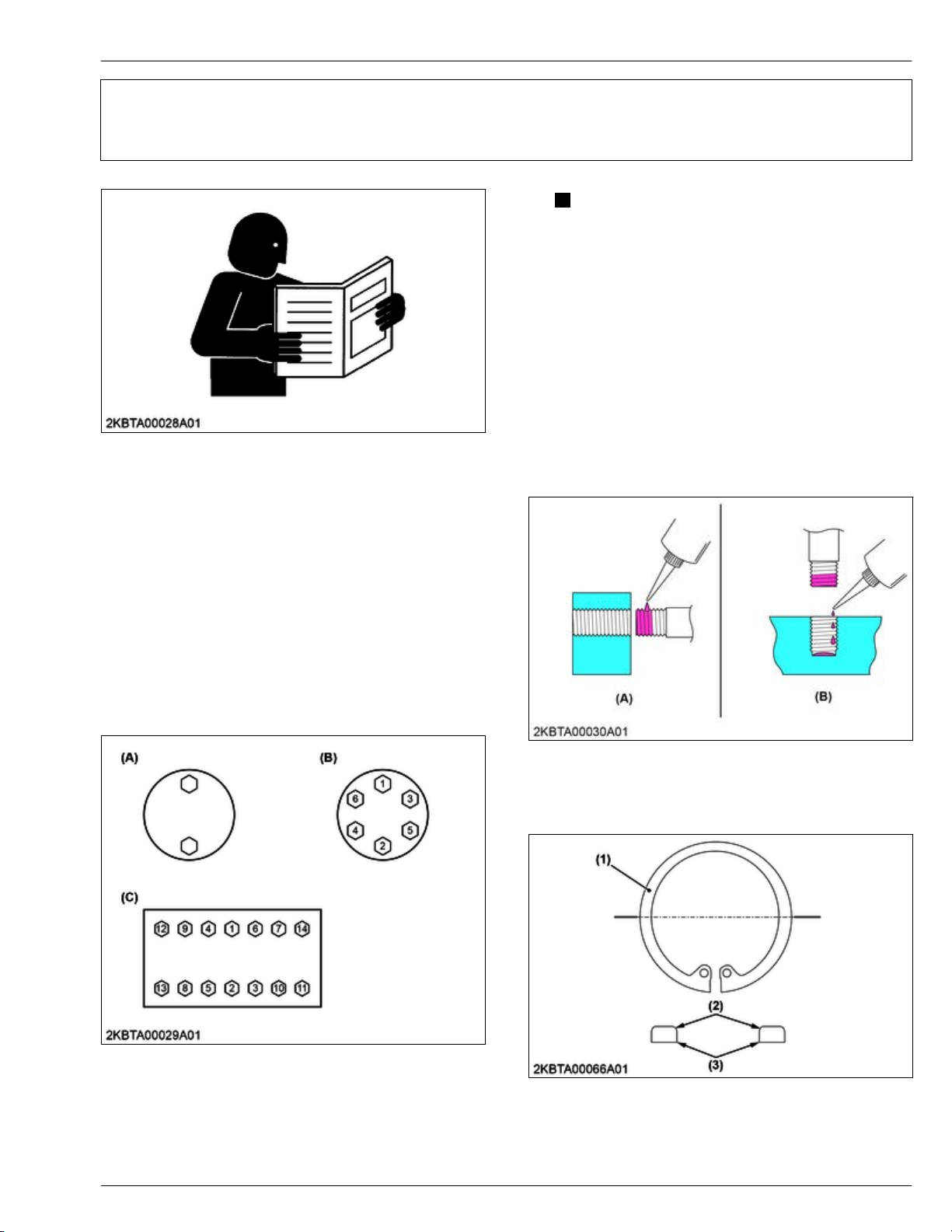
GENERAL WORKING PRECAUTIONS
D1803-CR-E4,D1803-CR-TE4,D1803-CR-TIE4,V2403-CR-E4,V2403-CR-TE4,V2403-CR-TE4BG,V2403-CR-TIE4
2-1
KiSC issued 12, 2018 A
1. Tightening bolts and nuts 2. GENERAL
GENERAL WORKING PRECAUTIONS
NOTE
– Tighten the bolts and nuts alternately from
top to bottom and left to right so the torque
is distributed evenly.
– Gradually tighten the bolts and nuts two or
three times.
2. Applying thread-locking fluid
1. Clean and dry the location where a thread-locking
fluid
will be applied with a solvent to remove
moisture, oil, and dirt.
2. Apply the thread-locking fluid to the tip of the bolt.
• When servicing, observe the safety regulations in
the operator's manual and workshop manual.
Clean the machine before maintenance.
•
• Before working, remove the negative (-) terminal
from the battery or turn off the battery isolator
switch.
• Disassemble the machine at a clean location.
• Whenever a special tool is required, use the special
tool that Kubota recommends. Or, craft the special
tools according to the illustrations in this manual.
• Use genuine Kubota parts to ensure safety and
machine performance.
3. If the threads are large, apply the thread-locking
fluid all around the bolt hole.
1. Tightening bolts and nuts
(A) Alternately
(B) Diagonally
• T
ighten the bolts and nuts with their specified
torque.
(C) Diagonally from center to
outside
(A) Bolt hole (bolts, nuts) (B) Screw hole
3. Installing circlips
(3)
(1) Circlip
Rounded side
(2)
Angular side
Page 26
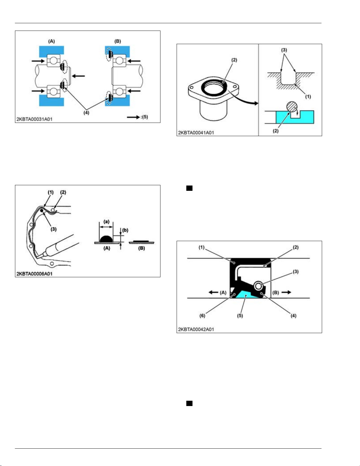
2. GENERAL
2-2
D1803-CR-E4,D1803-CR-TE4,D1803-CR-TIE4,V2403-CR-E4,V2403-CR-TE4,V2403-CR-TE4BG,V2403-CR-TIE4
KiSC issued 12, 2018 A
GENERAL WORKING PRECAUTIONS
4. Handling liquid gasket
5. Replacing O-rings
(4) Side that receives force
(5) Force
External circlip
(A)
(B) Internal circlip
• When installing the circlip, assemble the circlip's
angular
side (3) toward the side that receives force
(4) as shown in the figure.
4. Handling liquid gasket
(1) Application route
(2)
Bolt hole
Dowel pin
(3)
(A) Correct
(B) Incorrect
(a) 3.0 to 3.5 mm (0.12 to
0.13 in.)
(b) 3.0 to 5.0 mm (0.12 to
0.19 in.)
(1) O-ring groove
(2) O-ring
(3)
Burr
1. Remove the burr and clean the O-ring groove.
2. Lubricate
O-ring. Do not apply any grease to
the
the floating seal.
3. Put the O-ring in the groove.
NOTE
• Do not twist the O-ring.
•
Remove the burr to avoid damage on the Oring caused by the burr.
6. Replacing oil seals
• Use the specified liquid gasket.
• When using
liquid gasket, fully remove the old
gasket and grease or oil.
• When applying liquid gasket, apply it on the joint
surface with a thickness of 3.0 to 5.0 mm (0.12 to
0.13 in.) without making any gaps.
• When applying liquid gasket near the bolt hole (2),
apply it in the inner side.
• If there is a risk of oil leakage or if the hole goes all
the way through when applying liquid gasket near
the dowel pin (3) hole, apply it in the inner side.
If there is no concern of oil leakage, apply it on the
(1) Packing
(2)
Metal ring
Spring
(3)
(4) Seal lip
1. Do
not face the lip of the oil seal in the wrong
direction.
Face the main lip toward the material to
be sealed.
2. Use a press to install the oil seal until firmly fixed to
the boss.
outer side.
• Reassemble within 15 minutes after applying; wait
for 30 minutes or more then fill with oil.
NOTE
• In cases
when installing an oil seal without a
press, place a wooden board on the seal
and gently tap the board with a hammer;
install the oil seal straightly and evenly.
(5) Grease
(6) Dust lip
(A) Air side
(B) Oil side
Page 27

GENERAL WORKING PRECAUTIONS
D1803-CR-E4,D1803-CR-TE4,D1803-CR-TIE4,V2403-CR-E4,V2403-CR-TE4,V2403-CR-TE4BG,V2403-CR-TIE4
2-3
KiSC issued 12, 2018 A
7. Handling the battery 2. GENERAL
3. Grease the seal lip and dust lip.
NOTE
• If the
seal has a dust lip, grease the gap
between the lips.
• After oil seals are replaced, grease the
moving parts around the lip to prevent the
dry surfaces from wearing against each
other during engine start up.
7. Handling the battery
CAUTION
• When removing
negative (-) terminal first.
• When installing battery cables, connect positive
(+) terminal first.
battery cables, disconnect
• Tighten the electrical terminals securely.
(A) Correct (B) Incorrect: loose bolt
• Check the
electrical terminal protection and
clamping conditions before connecting the battery
cable.
(1) Battery negative (-) terminal (2) Battery positive (+) terminal
• Do not install any battery with a capacity (Ah) other
than is specified.
• Securely attach the terminal covers on the cables
when connecting the cables to the battery terminal
posts. There is a danger of short-circuiting if the tip
of the cables attached to the battery terminal post is
exposed.
• Do not allow dirt and dust to collect on the battery.
• Apply grease thinly to the battery terminal posts to
prevent corrosion.
8. Handling electrical wiring
CAUTION
• Do not
come in contact with other components.
• Do not clamp the electrical wiring to fuel hoses.
• If the electrical wiring is damaged, repair it with
an insulating tape or rat-proof tape, or replace
the wiring with a new one.
• Do not alter the electrical device and wiring.
put an unprotected electrical wiring to
(1) Covered completely with a
protection cover
• Keep the wiring away from hazardous positions
such as rotating parts or high-temperature sections.
(2) Hazardous position
(3) Wiring position: poor
Wiring position: good
(4)
• Repair
replace damaged or old wiring
or
(5) Hazardous position
immediately.
Page 28
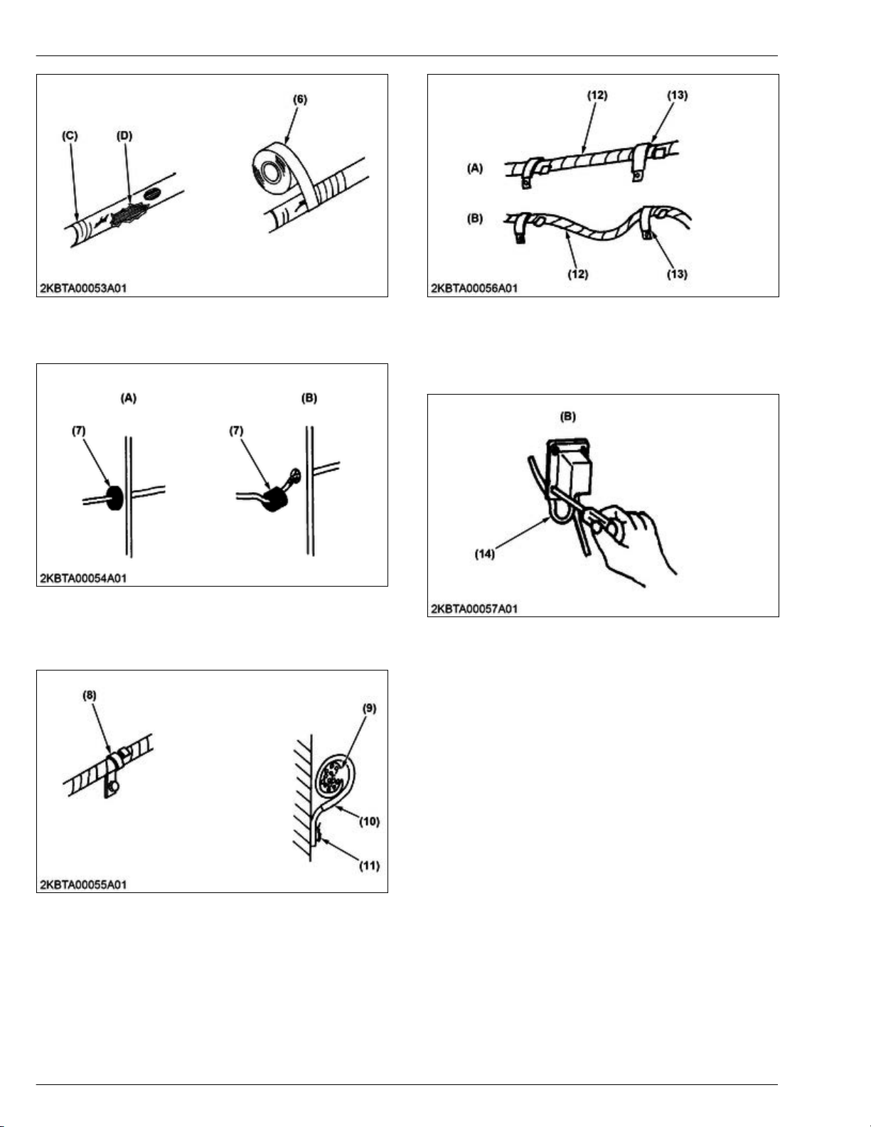
2. GENERAL
2-4
D1803-CR-E4,D1803-CR-TE4,D1803-CR-TIE4,V2403-CR-E4,V2403-CR-TE4,V2403-CR-TE4BG,V2403-CR-TIE4
KiSC issued 12, 2018 A
GENERAL WORKING PRECAUTIONS
9. Handling fuses
(6) Insulating tape
(C) Damaged
(D)
Torn
• Install the grommet securely.
(7) Grommet
(A)
Correct
• Clamp the
electrical wiring securely. Do not
Incorrect: poor installation
(B)
damage the electrical wiring by the clamp.
(12) Electrical wiring
(13) Clamp
Correct
(A)
(B) Incorrect
• Do not pinch the electrical wiring when installing
parts.
(14) Electrical wiring (B) Incorrect
9. Handling fuses
• Always use fuses of the specified capacity.
• Do not use steel or copper wiring instead of fuse.
•
Do not install work light or radio without auxiliary
power line.
• Do not install auxiliaries to the fuses. The fuses
may blow.
(8) Clamp: clamped spirally
(9) Electrical wiring
(10)
Clamp
• Clamp
the electrical wiring correctly. Do not slack,
(11) Welding point
twist, and pull.
In cases of connecting the electrical wiring to
•
moving or vibrating locations, make sure to clamp
the electrical wiring loosely.
Page 29
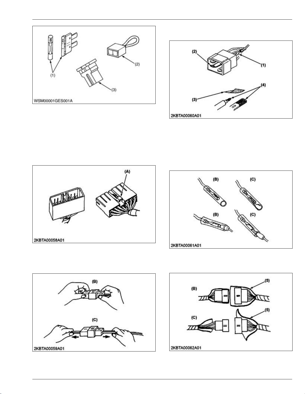
GENERAL WORKING PRECAUTIONS
D1803-CR-E4,D1803-CR-TE4,D1803-CR-TIE4,V2403-CR-E4,V2403-CR-TE4,V2403-CR-TE4BG,V2403-CR-TIE4
2-5
KiSC issued 12, 2018 A
10. Handling connectors 2. GENERAL
• If
the terminal is rusted, remove rust with
sandpaper
.
(1) Fuse
(2) Fusible link
Slow blow fuse
(3)
10. Handling connectors
• When disconnecting the locking connectors, be
to disengage the lock before disconnecting.
sure
There are two kinds of locks: one requires pressing
and the other requires pulling.
(A) Press
• Pull the connector body securely when
disconnecting the connectors.
•
Do not pull the wire harness to separate.
(1) Missing terminal
(2) Bent terminal
Sandpaper
(3)
• Cover
terminals
the female bullet terminals and male bullet
securely with the waterproof plastic
(4) Rust
covers.
• Make sure that the bullet terminals are secure and
connected securely to the tip.
(B) Correct (C) Incorrect
• Cover the female connectors and male connectors
securely with the waterproof plastic covers.
(B) Correct (C) Incorrect
(5) Cover
(B) Correct
• Make sure the terminal condition of the connectors
is not bent, rusty, and so on.
(C)
Incorrect
Page 30
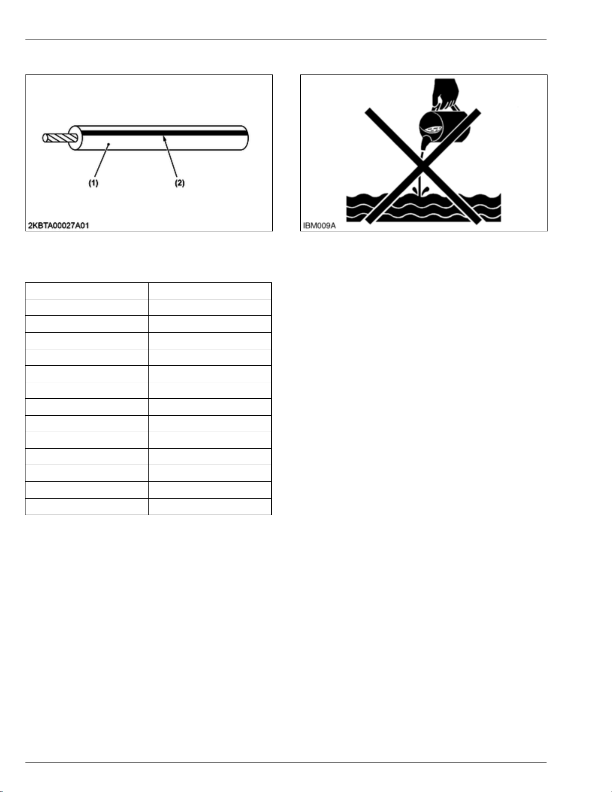
2. GENERAL
2-6
D1803-CR-E4,D1803-CR-TE4,D1803-CR-TIE4,V2403-CR-E4,V2403-CR-TE4,V2403-CR-TE4BG,V2403-CR-TIE4
KiSC issued 12, 2018 A
GENERAL WORKING PRECAUTIONS
11. Wiring color
11. Wiring color
(1) Wire color (2) Stripe
• Wire colors are specified in the color codes.
• This symbol of "/" shows color with stripe(s).
W
iring Colors Color code
Black B
Brown BR, Br
Green G
Gray GY, GR
Blue L
Light green LG, Lg
Orange OR, O
Pink P
Purple PU, V, Pu
Red R
Sky blue SB, Sb
White W
Yellow Y
(An example)
W/R:
Red stripe on white color
12. Dispose fluids correctly
• Do not dispose fluids on the ground, down the
drain,
environmental protection regulations when you
dispose of oil, fuel, coolant, electrolyte, and other
dangerous materials.
into a stream, pond, or lake. Obey related
Page 31

GENERAL MACHINE INFORMATION
D1803-CR-E4,D1803-CR-TE4,D1803-CR-TIE4,V2403-CR-E4,V2403-CR-TE4,V2403-CR-TE4BG,V2403-CR-TIE4
2-7
KiSC issued 12, 2018 A
1. Engine identification 2. GENERAL
GENERAL MACHINE INFORMATION
1. Engine identification
1.1 Engine model name and engine serial number
(1) Engine model name and se-
rial number
You must identify the engine model name and serial
number before you start a job.
When you
tell your engine model name and serial number.
Engine serial number
The engine serial number is an identified number for
the engine.
It appears after the engine model name.
It shows the month and year of manufacture as below.
Engine series
get in touch with the manufacturer, always
Number or alphabet Series
1 05 (include: WG)
2 V3 (include: WG)
3 08
4 SM (include: WG)
5 Air cooled gasoline
6 GZ, OC, AC, EA, E
7 03 (include: WG)
8 07
A EA, RK
B 03 (KET production)
C V3, 07 (KEW production)
Production year
Alphabet or number Year
1 2001
2 2002
3 2003
4 2004
5 2005
6 2006
7 2007
8 2008
9 2009
A 2010
B 2011
C 2012
D 2013
E 2014
F 2015
G 2016
H 2017
J 2018
K 2019
L 2020
M 2021
N 2022
P 2023
R 2024
S 2025
T 2026
V 2027
* Alphabetical letters "I" and "O" are not used.
Page 32

2. GENERAL
2-8
D1803-CR-E4,D1803-CR-TE4,D1803-CR-TIE4,V2403-CR-E4,V2403-CR-TE4,V2403-CR-TE4BG,V2403-CR-TIE4
KiSC issued 12, 2018 A
GENERAL MACHINE INFORMATION
1. Engine identification
Production month and lot number
Month Engine lot number
January A0001~A9999 B0001~
February C0001~C9999 D0001~
March E0001~E9999 F0001~
April G0001~G9999 H0001~
May J0001~J9999 K0001~
June L0001~L9999 M0001~
July N0001~N9999 P0001~
August Q0001~Q9999 R0001~
September S0001~S9999 T0001~
October U0001~U9999 V0001~
November W0001~W9999 X0001~
December Y0001~Y9999 Z0001~
* Alphabetical letters "I" and "O" are not used.
Example of model name and engine serial number
1.2 E4B engine
(a) D1803: Engine model name
(b) 7: Engine series (03 series)
C: Production year (2012)
(c)
(d) U: Production month (Octo-
ber)
(e) 1237: Lot number (0001~
9999 or A001~Z999)
(1) EU regulation engine output
classification category
Category (1)
K From 19 to 37 kW STAGE IIIB
P
N
M
Category (2)
EF
Engine output
classification
From 37 to less
than 56 kW
From 56 to less
than 75 kW
From 75 to less
than 130 kW
Engine output
classification
Less than 19 kW Tier 4
From 19 to less
than 56 kW
From 56 to less
than 75 kW
From 75 to less
than 130 kW
(2) "E4B" engines are identified
with "EF" at the end of the
Model designation, on the
US EPA label.
"E4B" designates some In-
ier 4 / Tier 4 models,
terim T
depending on engine output
classification.
EU regulation
STAGE IIIB
STAGE IIIB
STAGE IIIB
EPA regulation
Interim Tier 4
Interim Tier 4
Interim Tier 4
The emission controls previously implemented in
various
countries
to prevent air pollution will be stepped
up as Nonroad Emission Standards continue to
Page 33

GENERAL MACHINE INFORMATION
D1803-CR-E4,D1803-CR-TE4,D1803-CR-TIE4,V2403-CR-E4,V2403-CR-TE4,V2403-CR-TE4BG,V2403-CR-TIE4
2-9
KiSC issued 12, 2018 A
1. Engine identification 2. GENERAL
change. The timing or applicable date of the specific
Nonroad
Emission
regulations depends on the engine
output classification.
Over the past several years, Kubota has been
supplying diesel engines that comply with regulations in
the respective countries affected by Nonroad Emission
regulations. For Kubota Engines, E4B will be the
designation that identifies engine models affected by
the next emission phase.
When servicing or repairing ###-E4B series engines,
use only replacement parts for that specific E4B
engine, designated by the appropriate E4B Kubota
Parts List and perform all maintenance services listed
in the appropriate Kubota Operator's Manual or in the
appropriate E4B Kubota Workshop Manual. Use of
incorrect replacement parts or replacement parts from
other emission level engines (for example: E3B
engines), may result in emission levels out of
compliance with the original E4B design and EPA or
other applicable regulations. Please refer to the
emission label located on the engine head cover to
identify Output classification and Emission Control
Information. E4B engines are identified with "EF" at the
end of the Model designation, on the US EPA label.
Please note: E4B is not marked on the engine.
Example: Engine model name D1803-CR-E4-XXXX or
D1803-CR-TE4-XXXX
1.3 Cylinder number
2. Muffler full assembly identification
2.1 Part number and serial number (DPF)
Diesel particulate filter (hereinafter referred to as
the "DPF") muffler full assembly serial number
You
must keep the records of the filter comp (DPF) part
number and serial number (3) and catalyst (DOC) part
number and serial number (4) before you remove the
DPF for cleaning.
(1) DPF muffler assembly part
number and serial number
(2)
DPF muf
part number and serial number
fler full assembly
(3) Filter comp (DPF) part num-
ber and serial number
(4) Catalyst (DOC) part number
and serial number
You can see the cylinder numbers of Kubota diesel
engine in
the figure. The sequence of cylinder numbers
is No.1, No.2, No.3 and No.4 and it starts from the gear
case cover side.
Page 34

GENERAL MACHINE INFORMATION
2-10
D1803-CR-E4,D1803-CR-TE4,D1803-CR-TIE4,V2403-CR-E4,V2403-CR-TE4,V2403-CR-TE4BG,V2403-CR-TIE4
KiSC issued 12, 2018 A
2. GENERAL
3. Specifications
3.1 Specification for D1803-CR-E4, TE4
Model D1803-CR-E4 D1803-CR-TE4
Number of cylinder 3
Engine type Vertical, water-cooled, 4-cycle diesel
Bore × Stroke 87 × 102.4 mm (3.43 × 4.031 in.)
Total displacement 1826 cm3 (11
SAE gross continuous
SAE gross intermittent
Maximum bare speed 2900 min-1 (rpm)
Minimum bare idling
speed
Combustion chamber Reentrant type (Direct injection)
Fuel supply pump
Governor system
Injector
Fuel supply timing
Fuel injection pressure
Direction of rotation Counter-clockwise (Viewed from flywheel side)
Firing order 1-2-3
Compression ratio 18.1
Lubricating system Forced lubrication by trochoid pump
Oil pressure indicating Electrical type switch
Lubricating filter Full flow paper filter (Cartridge type)
Cooling system Pressurized radiator, forced circulation with water pump
Starting system Electric starting with starter
Starter motor 12 V, 1.4 kW
Starting support device By glow plug in combustion chamber
EGR External EGR (EGR cooler + Electric EGR valve + Reed valve)
Battery 12 V, 88 AH (105E41R) equivalent
Charging alternator 12 V, 480 W
Fuel Diesel fuel No. 2-D S15, see page 3-1.
Lubricating oil (API classification)
Lubricating oil capacity 7.0 L (1.8 U.S.gals, 1.5 Imp.gals)
Weight (Dry) 185 kg (408 lbs) 196 kg (432 lbs)
24.3 kW / 2700 min-1 (rpm)
(32.6 HP / 2700 min-1 (rpm))
28.0 kW / 2700 min-1 (rpm)
(37.5 HP / 2700 min-1 (rpm))
800 min-1 (rpm)
BOSCH common rail system
Class CJ-4 lubricating oil as per API classification is recommended.
For details on recommended lubricating oils, see page 3-1.
1.4 cu.in.)
32.1 kW / 2700 min-1 (rpm)
(43.0 HP / 2700 min-1 (rpm))
37.0 kW / 2700 min-1 (rpm)
(49.6 HP / 2700 min-1 (rpm))
3. Specifications
NOTE
• The specification described above is of the standard engine of each model.
Conversion formula: HP = 0.746 kW, PS = 0.7355 kW.
•
Page 35

GENERAL MACHINE INFORMATION
D1803-CR-E4,D1803-CR-TE4,D1803-CR-TIE4,V2403-CR-E4,V2403-CR-TE4,V2403-CR-TE4BG,V2403-CR-TIE4
2-11
KiSC issued 12, 2018 A
3. Specifications 2. GENERAL
3.2 Specification for V2403-CR-E4, TE4
Model V2403-CR-E4 V2403-CR-TE4
Number of cylinder 4
Engine type Vertical, water-cooled, 4-cycle diesel
Bore × Stroke 87 × 102.4 mm (3.43 × 4.031 in.)
Total displacement 2434 cm3 (148.5 cu.in.)
SAE gross continuous
SAE gross intermittent
Maximum bare speed 2900 min-1 (rpm)
Minimum bare idling
speed
Combustion chamber Reentrant type (Direct injection)
Fuel supply pump
Governor system
Injector
Fuel supply timing
Fuel injection pressure
Direction of rotation Counter-clockwise (V
Firing order 1-3-4-2
Compression ratio 18.1
Lubricating system Forced lubrication by trochoid pump
Oil pressure indicating Electrical type switch
Lubricating filter Full flow paper filter (Cartridge type)
Cooling system Pressurized radiator, forced circulation with water pump
Starting system Electric starting with starter
Starter motor 12 V, 2.0 kW
Starting support device By glow plug in combustion chamber
EGR External EGR (EGR cooler + Electric EGR valve + Reed valve)
Battery 12 V, 92 AH (130E41R) equivalent
Charging alternator 12 V, 480 W
Fuel Diesel fuel No. 2-D S15, see page 3-1.
Lubricating oil (API classification)
Lubricating oil capacity 9.5 L (2.5 U.S.gals, 2.1 Imp.gals)
Weight (Dry) 221 kg (487 lbs) 233 kg (514 lbs)
32.4 kW / 2700 min-1 (rpm)
(43.4 HP / 2700 min-1 (rpm))
37.4 kW / 2700 min-1 (rpm)
(50.2 HP / 2700 min-1 (rpm))
800 min-1 (rpm)
BOSCH common rail system
iewed from flywheel side)
Class CJ-4 lubricating oil as per API classification is recommended.
For details on recommended lubricating oils, see page 3-1.
42.1 kW / 2700 min-1 (rpm)
(56.5 HP / 2700 min-1 (rpm))
48.6 kW / 2700 min-1 (rpm)
(65.2 HP / 2700 min-1 (rpm))
NOTE
• The specification described above is of the standard engine of each model.
Conversion formula: HP = 0.746 kW, PS = 0.7355 kW.
•
Page 36

GENERAL MACHINE INFORMATION
2-12
D1803-CR-E4,D1803-CR-TE4,D1803-CR-TIE4,V2403-CR-E4,V2403-CR-TE4,V2403-CR-TE4BG,V2403-CR-TIE4
KiSC issued 12, 2018 A
2. GENERAL
3. Specifications
3.3 Specification for D1803-CR-TIE4, V2403-CR-TIE4
Model D1803-CR-TIE4 (DOC only) V2403-CR-TIE4 (DOC only)
Number of cylinder 3 4
Engine type Vertical, water-cooled, 4-cycle diesel
Bore × Stroke 87 × 102.4 mm (3.43 × 4.031 in.)
Total displacement 1826 cm3 (11
SAE gross continuous
SAE gross intermittent
Maximum bare speed 2900 min-1 (rpm)
Minimum bare idling
speed
Combustion chamber Reentrant type (Direct injection)
Fuel supply pump
Governor system
Injector
Fuel supply timing
Fuel injection pressure
Direction of rotation Counter-clockwise (Viewed from flywheel side)
Firing order 1-2-3 1-3-4-2
Compression ratio 16.0
Lubricating system Forced lubrication by trochoid pump
Oil pressure indicating Electrical type switch
Lubricating filter Full flow paper filter (Cartridge type)
Cooling system Pressurized radiator, forced circulation with water pump
Starting system Electric starting with starter
Starter motor 12 V, 1.4 kW 12 V, 2.0 kW
Starting support device By glow plug in combustion chamber
EGR External EGR (EGR cooler + Electric EGR valve + Reed valve)
Battery 12 V, 88 AH (105E41R) equivalent 12 V, 92 AH (130E41R) equivalent
Charging alternator 12 V, 480 W
Fuel Diesel fuel No. 2-D S15, see page 3-1.
Lubricating oil (API classification)
Lubricating oil capacity 7.0 L (1.8 U.S.gals, 1.5 Imp.gals) 9.5 L (2.5 U.S.gals, 2.1 Imp.gals)
Weight (Dry) 195 kg (430 lbs) 232 kg (511 lbs)
32.1 kW / 2700 min-1 (rpm)
(43.0 HP / 2700 min-1 (rpm))
37.0 kW / 2700 min-1 (rpm)
(49.6 HP / 2700 min-1 (rpm))
1.4 cu.in.) 2434 cm3 (148.5 cu.in.)
42.1 kW / 2700 min-1 (rpm)
(56.5 HP / 2700 min-1 (rpm))
48.6 kW / 2700 min-1 (rpm)
(65.2 HP / 2700 min-1 (rpm))
800 min-1 (rpm)
BOSCH common rail system
Class CJ-4 lubricating oil as per API classification is recommended.
For details on recommended lubricating oils, see page 3-1.
NOTE
• The specification described above is of the standard engine of each model.
Conversion formula: HP = 0.746 kW, PS = 0.7355 kW.
•
Page 37

GENERAL MACHINE INFORMATION
D1803-CR-E4,D1803-CR-TE4,D1803-CR-TIE4,V2403-CR-E4,V2403-CR-TE4,V2403-CR-TE4BG,V2403-CR-TIE4
2-13
KiSC issued 12, 2018 A
3. Specifications 2. GENERAL
3.4 Specification for V2403-CR-TE4BG
Model V2403-CR-TE4BG
Number of cylinder 4
Engine type Vertical, water-cooled, 4-cycle diesel
Bore × Stroke 87 × 102.4 mm (3.43 × 4.031 in.)
Total displacement 2434 cm3 (148.5 cu.in.)
SAE gross continuous
SAE gross intermittent
Maximum bare speed 2000 min-1 (rpm)
Minimum bare idling speed 2000 min-1 (rpm)
Combustion chamber Reentrant type (Direct injection)
Fuel supply pump
Governor system
Injector
Fuel supply timing
Fuel injection pressure
Direction of rotation Counter-clockwise (Viewed from flywheel side)
Firing order 1-3-4-2
Compression ratio 18.1
Lubricating system Forced lubrication by trochoid pump
Oil pressure indicating Electrical type switch
Lubricating filter Full flow paper filter (Cartridge type)
Cooling system Pressurized radiator, forced circulation with water pump
Starting system Electric starting with starter
Starter motor 12 V, 2.0 kW
Starting support device By glow plug in combustion chamber
EGR External EGR (EGR cooler + Electric EGR valve + Reed valve)
Battery 12 V, 92 AH (130E41R) equivalent
Charging alternator 12 V, 720 W
Fuel Diesel fuel No. 2-D S15, see page 3-1.
Lubricating oil (API classification)
Lubricating oil capacity 9.5 L (2.5 U.S.gals, 2.1 Imp.gals)
Weight (Dry) 230 kg (507 lbs)
Class CJ-4 lubricating oil as per API classification is recommended.
For details on recommended lubricating oils, see page 3-1
31.7 kW / 1800 min-1 (rpm)
(42.6 HP / 1800 min-1 (rpm))
36.5 kW / 1800 min-1 (rpm)
(48.9 HP / 1800 min-1 (rpm))
BOSCH common rail system
.
NOTE
• The specification described above is of the standard engine of each model.
Conversion formula: HP = 0.746 kW, PS = 0.7355 kW.
•
Page 38

2. GENERAL
2-14
D1803-CR-E4,D1803-CR-TE4,D1803-CR-TIE4,V2403-CR-E4,V2403-CR-TE4,V2403-CR-TE4BG,V2403-CR-TIE4
KiSC issued 12, 2018 A
4. Performance curves
4.1 Performance curve for D1803-CR-E4
D1803-CR-E4
GENERAL MACHINE INFORMATION
4. Performance curves
(1) Torque
(2) Brake specific fuel consump-
tion (B.S.F
.C.)
(3) Engine speed
(4) Brake horsepower
(5) Gross intermittent torque
(6) Gross intermittent brake
horsepower
(7) Gross intermittent B.S.F.C.
Page 39

GENERAL MACHINE INFORMATION
D1803-CR-E4,D1803-CR-TE4,D1803-CR-TIE4,V2403-CR-E4,V2403-CR-TE4,V2403-CR-TE4BG,V2403-CR-TIE4
2-15
KiSC issued 12, 2018 A
4. Performance curves 2. GENERAL
4.2 Performance curve for D1803-CR-TE4
D1803-CR-TE4
(1) Torque
(2) Brake specific fuel consump-
tion (B.S.F
.C.)
(3) Engine speed
(4) Brake horsepower
(5) Gross intermittent torque
(6) Gross intermittent brake
horsepower
(7) Gross intermittent B.S.F.C.
Page 40

2. GENERAL
2-16
D1803-CR-E4,D1803-CR-TE4,D1803-CR-TIE4,V2403-CR-E4,V2403-CR-TE4,V2403-CR-TE4BG,V2403-CR-TIE4
KiSC issued 12, 2018 A
4.3 Performance curve for D1803-CR-TIE4
D1803-CR-TIE4
GENERAL MACHINE INFORMATION
4. Performance curves
(1) Torque
(2) Brake specific fuel consump-
tion (B.S.F
.C.)
(3) Engine speed
(4) Brake horsepower
(5) Gross intermittent torque
(6) Gross intermittent brake
horsepower
(7) Gross intermittent B.S.F.C.
Page 41

GENERAL MACHINE INFORMATION
D1803-CR-E4,D1803-CR-TE4,D1803-CR-TIE4,V2403-CR-E4,V2403-CR-TE4,V2403-CR-TE4BG,V2403-CR-TIE4
2-17
KiSC issued 12, 2018 A
4. Performance curves 2. GENERAL
4.4 Performance curve for V2403-CR-E4
V2403-CR-E4
(1) Torque
(2) Brake specific fuel consump-
tion (B.S.F
.C.)
(3) Engine speed
(4) Brake horsepower
(5) Gross intermittent torque
(6) Gross intermittent brake
horsepower
(7) Gross intermittent B.S.F.C.
Page 42

2. GENERAL
2-18
D1803-CR-E4,D1803-CR-TE4,D1803-CR-TIE4,V2403-CR-E4,V2403-CR-TE4,V2403-CR-TE4BG,V2403-CR-TIE4
KiSC issued 12, 2018 A
4.5 Performance curve for V2403-CR-TE4
V2403-CR-TE4
GENERAL MACHINE INFORMATION
4. Performance curves
(1) Torque
(2) Brake specific fuel consump-
tion (B.S.F
.C.)
(3) Engine speed
(4) Brake horsepower
(5) Gross intermittent torque
(6) Gross intermittent brake
horsepower
(7) Gross intermittent B.S.F.C.
Page 43

GENERAL MACHINE INFORMATION
D1803-CR-E4,D1803-CR-TE4,D1803-CR-TIE4,V2403-CR-E4,V2403-CR-TE4,V2403-CR-TE4BG,V2403-CR-TIE4
2-19
KiSC issued 12, 2018 A
4. Performance curves 2. GENERAL
4.6 Performance curve for V2403-CR-TIE4
V2403-CR-TIE4
(1) Torque
(2) Brake specific fuel consump-
tion (B.S.F
.C.)
(3) Engine speed
(4) Brake horsepower
(5) Gross intermittent torque
(6) Gross intermittent brake
horsepower
(7) Gross intermittent B.S.F.C.
Page 44

2. GENERAL
2-20
D1803-CR-E4,D1803-CR-TE4,D1803-CR-TIE4,V2403-CR-E4,V2403-CR-TE4,V2403-CR-TE4BG,V2403-CR-TIE4
KiSC issued 12, 2018 A
5. Dimensions
5.1 Dimensions
GENERAL MACHINE INFORMATION
5. Dimensions
D1803-CR-E4 D1803-CR-TE4 D1803-CR-TIE4
A 744 mm (29.3 in.) 744 mm (29.3 in.) 758 mm (29.8 in.)
B 507 mm (20.0 in.) 513 mm (20.2 in.) 513 mm (20.2 in.)
C 721 mm (28.4 in.) 735 mm (28.9 in.) 744 mm (29.3 in.)
V2403-CR-E4
A 869 mm (34.2 in.) 869 mm (34.2 in.) 854 mm (33.6 in.)
B 517 mm (20.4 in.) 517 mm (20.4 in.) 517 mm (20.4 in.)
C 721 mm (28.4 in.) 735 mm (28.9 in.) 744 mm (29.3 in.)
V2403-CR-TE4
V2403-CR-TE4BG
V2403-CR-TIE4
Page 45

GENERAL MACHINE INFORMA
D1803-CR-E4,D1803-CR-TE4,D1803-CR-TIE4,V2403-CR-E4,V2403-CR-TE4,V2403-CR-TE4BG,V2403-CR-TIE4
2-21
KiSC issued 12, 2018 A
TION
6. Wiring diagram 2. GENERAL
6. Wiring diagram
6.1 Engine intermediate harness (Engine side harness)
(1) - CAN and EGR
(2) CN202 Coolant temperature sensor
(3) CN204 Crankshaft position sensor
(4) CN205 Camshaft position sensor
(5) CN206 Rail pressure sensor
(6) CN207 Oil pressure switch
(7) CN208 Boost pressure sensor
(8) CN209 Suction control valve (SCV)
(9) CN210 Intake throttle valve
(10) - Shield cable
NOTE
• The figure shows the pin arrangement of the connector housing viewed from wire side, not mating side.
Page 46

2. GENERAL
2-22
D1803-CR-E4,D1803-CR-TE4,D1803-CR-TIE4,V2403-CR-E4,V2403-CR-TE4,V2403-CR-TE4BG,V2403-CR-TIE4
KiSC issued 12, 2018 A
GENERAL MACHINE INFORMA
6. Wiring diagram
TION
(11) - CAN and EGR
(12) CN223 EGR valve
(13) CN224 / CN225 CAN tool
(14) CN226 Resistance connector (120 Ω)
(15) - Shield cable
NOTE
• The figure shows the pin arrangement of the connector housing viewed from wire side, not mating side.
Page 47

GENERAL MACHINE INFORMA
D1803-CR-E4,D1803-CR-TE4,D1803-CR-TIE4,V2403-CR-E4,V2403-CR-TE4,V2403-CR-TE4BG,V2403-CR-TIE4
2-23
KiSC issued 12, 2018 A
TION
6. Wiring diagram 2. GENERAL
6.2 Injector intermediate harness (Engine side harness)
(1) CN305 Pin plated terminal
(2) - Shield cable
(3) CN301 Injector 1
(4) CN302 Injector 4
(5) CN303 Injector 3
(6) CN304 Injector 2
* Injector 4 is equipped only V2403 model.
*
NOTE
• The figure shows the pin arrangement of the connector housing viewed from wire side, not mating side.
Page 48

GENERAL MACHINE INFORMATION
2-24
D1803-CR-E4,D1803-CR-TE4,D1803-CR-TIE4,V2403-CR-E4,V2403-CR-TE4,V2403-CR-TE4BG,V2403-CR-TIE4
KiSC issued 12, 2018 A
2. GENERAL
6.3 Engine ECU intermediate harness (OEM side harness)
6. Wiring diagram
(1) CN501 Engine ECU (1)
(2) CN502 Engine ECU (2)
(3) CN503 Engine ECU joint connector 1
(4) - Power unit
(5) -
(6) - Engine
(7) - Injector
Diesel Particulate Filter (Hereinafter referred
to as the "DPF")
Page 49

GENERAL MACHINE INFORMATION
D1803-CR-E4,D1803-CR-TE4,D1803-CR-TIE4,V2403-CR-E4,V2403-CR-TE4,V2403-CR-TE4BG,V2403-CR-TIE4
2-25
KiSC issued 12, 2018 A
6. Wiring diagram 2. GENERAL
NOTE
• The figure shows the pin arrangement of the connector housing viewed from wire side, not mating side.
(8) - Power unit
(9) CN401 Accel sensor
(10) CN408 Alternator
(11) CN402 Starter relay
(12) CN403 Starter
(13) CN404 Connector
(14) CN405 Connector
(15) CN413 Main relay
(16) - Glow
(17) CN416 Glow relay
(18) CN414 Connector
(19) CN415 Connector
(20) - Fuel feed pump
(21) - Battery unit
(22) - Battery
(23) - Key switch
(24) - Speed sensor
(25) - CAN for vehicle
(Continued)
Page 50

GENERAL MACHINE INFORMA
2-26
D1803-CR-E4,D1803-CR-TE4,D1803-CR-TIE4,V2403-CR-E4,V2403-CR-TE4,V2403-CR-TE4BG,V2403-CR-TIE4
KiSC issued 12, 2018 A
2. GENERAL
(26) CN407 CAN connector cap
(27) - Shield cable
6. Wiring diagram
NOTE
• The figure shows the pin arrangement of the connector housing viewed from wire side, not mating side.
TION
(28) - Diesel particulate filter (DPF)
(29) CN101 Exhaust gas temperature sensor (T2)
(30) CN102 Exhaust gas temperature sensor (T1)
(31) CN103 Exhaust gas temperature sensor (T0)
(32) CN104 Differential pressure sensor (ΔP)
(33) CN105 Air flow sensor
NOTE
• The figure shows the pin arrangement of the connector housing viewed from wire side, not mating side.
Page 51

GENERAL MACHINE INFORMATION
D1803-CR-E4,D1803-CR-TE4,D1803-CR-TIE4,V2403-CR-E4,V2403-CR-TE4,V2403-CR-TE4BG,V2403-CR-TIE4
2-27
KiSC issued 12, 2018 A
6. Wiring diagram 2. GENERAL
(34) - Engine
(35) - Shield cable
NOTE
• The figure shows the pin arrangement of the connector housing viewed from wire side, not mating side.
Page 52

2. GENERAL
2-28
D1803-CR-E4,D1803-CR-TE4,D1803-CR-TIE4,V2403-CR-E4,V2403-CR-TE4,V2403-CR-TE4BG,V2403-CR-TIE4
KiSC issued 12, 2018 A
GENERAL MACHINE INFORMA
6. Wiring diagram
TION
(36) - Injector
(37) - Shield cable
NOTE
• The figure shows the pin arrangement of the connector housing viewed from wire side, not mating side.
Page 53

GENERAL MACHINE INFORMATION
D1803-CR-E4,D1803-CR-TE4,D1803-CR-TIE4,V2403-CR-E4,V2403-CR-TE4,V2403-CR-TE4BG,V2403-CR-TIE4
2-29
KiSC issued 12, 2018 A
6. Wiring diagram 2. GENERAL
6.4 System wiring diagram for D1803-CR-E4, D1803-CR-TE4, V2403-CR-E4, V2403-CR-TE4, V2403-CR-TE4BG
D1803-CR-E4, D1803-CR-TE4, V2403-CR-E4, V2403-CR-TE4, V2403-CR-TE4BG
(1) Main relay (13) Injector 1 (25) Rail pressure sensor
(2) Fuel feed pump (14) Injector 4
(3) CAN1 connector (for service) (15) Injector 3 (27) Stop switch
(4) CAN2 connector (for vehicle) (16) Injector 2 (28) Parked regeneration switch
(5) EGR valve (17) Crankshaft position sensor (29) Parking switch
(6) Starter (18) Camshaft position sensor (30) Regeneration inhibit switch
*
(26) Boost pressure sensor
(Continued)
Page 54

GENERAL MACHINE INFORMA
2-30
D1803-CR-E4,D1803-CR-TE4,D1803-CR-TIE4,V2403-CR-E4,V2403-CR-TE4,V2403-CR-TE4BG,V2403-CR-TIE4
KiSC issued 12, 2018 A
2. GENERAL
(7) Air flow sensor (19) Accel sensor 1 (31) Neutral switch
(8) Intake throttle valve (20) Accel sensor 2 (32)
(9) Starter relay (21) Vehicle speed sensor (33)
(10) Battery (22) Differential pressure sensor (ΔP) (34)
(11) Glow relay (23) Suction control valve (SCV)
(12) Glow heater (24) Coolant temperature sensor
* Injector 4 is equipped only V2403 model.
Exhaust gas temperature sensor
(T0)
Exhaust gas temperature sensor
(T1)
Exhaust gas temperature sensor
(T2)
TION
6. Wiring diagram
Page 55

GENERAL MACHINE INFORMATION
D1803-CR-E4,D1803-CR-TE4,D1803-CR-TIE4,V2403-CR-E4,V2403-CR-TE4,V2403-CR-TE4BG,V2403-CR-TIE4
2-31
KiSC issued 12, 2018 A
6. Wiring diagram 2. GENERAL
6.5 System wiring diagram for D1803-CR-TIE4, V2403-CR-TIE4
D1803-CR-TIE4, V2403-CR-TIE4
(1) Main relay (10) Glow relay (19) Accel sensor 2
(2) Fuel feed pump (11) Glow heater (20) Suction control valve (SCV)
(3) CAN1 connector (for service) (12) Injector 1 (21) Coolant temperature sensor
(4) CAN2 connector (for vehicle) (13) Injector 4
(5) EGR valve (14) Injector 3 (23) Boost pressure sensor
(6) Starter (15) Injector 2 (24) Stop switch
(7) Air flow sensor (16) Crankshaft position sensor (25) Neutral switch
(8) Starter relay (17) Camshaft position sensor
*
(22) Rail pressure sensor
(Continued)
Page 56

2. GENERAL
2-32
D1803-CR-E4,D1803-CR-TE4,D1803-CR-TIE4,V2403-CR-E4,V2403-CR-TE4,V2403-CR-TE4BG,V2403-CR-TIE4
KiSC issued 12, 2018 A
(9) Battery (18) Accel sensor 1
* Injector 4 is equipped only V2403 model.
GENERAL MACHINE INFORMA
6. Wiring diagram
TION
Page 57

SPECIAL TOOLS
D1803-CR-E4,D1803-CR-TE4,D1803-CR-TIE4,V2403-CR-E4,V2403-CR-TE4,V2403-CR-TE4BG,V2403-CR-TIE4
2-33
KiSC issued 12, 2018 A
1. Diesel engine compression tester 2. GENERAL
SPECIAL TOOLS
1. Diesel engine compression tester
Use for measuring the diesel engine compression.
Code No.
07909-30208 (Assembly)
(1) Gauge
Page 58

2. GENERAL
2-34
D1803-CR-E4,D1803-CR-TE4,D1803-CR-TIE4,V2403-CR-E4,V2403-CR-TE4,V2403-CR-TE4BG,V2403-CR-TIE4
KiSC issued 12, 2018 A
2. Compression tester adapter K
Use for check compression pressure through glow plug hole.
NOTE
• This special tool is not provided, so make it referring to the figure.
A 3 mm dia. (0.1 in. dia.) through hole
B 16 mm dia. 18 mm thread (0.63 in. dia. 0.70 in. thread) (Special screw)
C M10 × 1.25
D 8.00 to 8.20 mm dia. (0.315 to 0.322 in. dia.)
E 118° to 120° (2.06 to 2.09 rad)
F 4.8 to 5.2 mm dia. (0.19 to 0.20 in. dia.)
G 17 mm (0.67 in.)
H 10 mm (0.39 in.)
I 41 mm (1.6 in.)
J 15 mm (0.59 in.)
K 49 mm (1.9 in.)
L 10 mm (0.39 in.)
M 15 mm (0.59 in.)
N 10 mm (0.39 in.)
O 100 mm (3.94 in.)
P 125 mm (4.92 in.)
C0.3 Chamfer 0.3 mm (Chamfer 0.01 in.)
Material SS400
SPECIAL TOOLS
2. Compression tester adapter K
Page 59

SPECIAL TOOLS
D1803-CR-E4,D1803-CR-TE4,D1803-CR-TIE4,V2403-CR-E4,V2403-CR-TE4,V2403-CR-TE4BG,V2403-CR-TIE4
2-35
KiSC issued 12, 2018 A
3. Oil pressure tester 2. GENERAL
3. Oil pressure tester
Use for measuring the engine oil pressure.
(1) Gauge
(2) Cable
Threaded joint
(3)
(4) Adapter 1
(5) Adapter 2
(6) Adapter 3
(7) Adapter 4
(8) Adapter 5
4. Valve guide replacing tool
Use for press out and press fit the valve guide.
NOTE
• This
special
referring to the figure.
tool is not provided, so make it
A 225 mm (8.86 in.)
B 70 mm (2.8 in.)
C 45 mm (1.8 in.)
D 20 mm dia. (0.79 in. dia.)
E
F
G 25 mm dia. (0.98 in. dia.)
H
I 5 mm (0.2 in.)
J 20 mm dia. (0.79 in. dia.)
K
L 8.90 to 9.10 mm (0.351 to 0.358 in.)
C1 Chamfer 1.0 mm (0.039 in.)
C2 Chamfer 2.0 mm (0.079 in.)
C0.3 Chamfer 0.3 mm (0.01 in.)
Material SS400
12.7 to 12.9 mm dia. (0.500 to 0.507 in.
dia.)
7.50 to 7.60 mm dia. (0.296 to 0.299 in.
dia.)
7.70 to 8.00 mm dia. (0.304 to 0.314 in.
dia.)
13.5 to 13.8 mm dia. (0.532 to 0.543 in.
dia.)
5. Bushing replacing tools
Use for press out and press fit the bushing.
NOTE
• This special
tool is not provided, so make it
referring to the figure.
Page 60

2. GENERAL
2-36
D1803-CR-E4,D1803-CR-TE4,D1803-CR-TIE4,V2403-CR-E4,V2403-CR-TE4,V2403-CR-TE4BG,V2403-CR-TIE4
KiSC issued 12, 2018 A
SPECIAL TOOLS
6. Flywheel stopper
For small end bushing
A 162 mm (6.38 in.)
B 35 mm (1.4 in.)
C 27 mm (1.1 in.)
D 35 mm dia. (1.4 in. dia.)
E
F
Material SS400
27.90 to 27.95 mm dia. (1.099 to 1.100 in.
dia.)
25.00 to 25.01 mm dia. (0.9843 to
0.9846 in. dia.)
For idle gear bushing
A 175 mm (6.89 in.)
B 40 mm (1.6 in.)
C 38 mm (1.5 in.)
D 45 mm dia. (1.8 in. dia.)
E
F
Material SS400
41.90 to 41.95 mm dia. (1.650 to 1.651 in.
dia.)
37.950 to 37.970 mm dia. (1.4941 to
1.4948 in. dia.)
A 140 mm (5.51 in.)
B 80 mm (3.1 in.)
C 49.3 mm (1.94 in.)
D 49.3 mm (1.94 in.)
E 23.8 mm (0.937 in.)
F 23.8 mm (0.937 in.)
G 11 mm dia. (0.43 in. dia.)
H 56.5 mm (2.22 in.)
I 56.5 mm (2.22 in.)
J 8 mm (0.3 in.)
Material SS400
7. Crankshaft bearing 1 replacing tool
Use for press out and press fit the crankshaft bearing 1.
NOTE
• This special
referring to the figure.
tool is not provided, so make it
6. Flywheel stopper
Use for loosening and tightening the flywheel screw.
NOTE
• This
special
make it by referring to the figure.
tool is not provided, therefore
Page 61

SPECIAL TOOLS
D1803-CR-E4,D1803-CR-TE4,D1803-CR-TIE4,V2403-CR-E4,V2403-CR-TE4,V2403-CR-TE4BG,V2403-CR-TIE4
2-37
KiSC issued 12, 2018 A
8. Auxiliary socket for fixing crankshaft sleeve 2. GENERAL
[1] Extracting tool
A 135 mm (5.31 in.)
B 72 mm (2.83 in.)
C R40 mm (R1.57 in.)
D 10 mm (0.39 in.)
E 20 mm (0.79 in.)
F 20 mm dia. (0.79 in. dia.)
G
H
Material SS400
64.80 to 64.90 mm dia. (2.552 to 2.555 in.
dia.)
59.80 to 59.90 mm dia. (2.355 to 2.358 in.
dia.)
[2] Inserting tool
A 130 mm (5.12 in.)
B 72 mm (2.83 in.)
C R40 mm (R1.57 in.)
D 9 mm (0.35 in.)
E 4 mm (0.16 in.)
F 20 mm (0.79 in.)
G 20 mm dia. (0.79 in. dia.)
H 68 mm dia. (2.68 in. dia.)
I
J
Material SS400
59.80 to 59.90 mm dia. (2.355 to 2.358 in.
dia.)
64.80 to 64.90 mm dia. (2.552 to 2.555 in.
dia.)
8. Auxiliary socket for fixing crankshaft sleeve
Use for fixing the crankshaft sleeve of the diesel
engine.
NOTE
• The special
them referring to the figure.
tools are not provided, so make
Page 62

2. GENERAL
2-38
D1803-CR-E4,D1803-CR-TE4,D1803-CR-TIE4,V2403-CR-E4,V2403-CR-TE4,V2403-CR-TE4BG,V2403-CR-TIE4
KiSC issued 12, 2018 A
(1) Stopper
(2)
Sleeve guide
A 80.0 mm (3.15 in.)
B 60.10 to 60.30 mm (2.367 to 2.374 in.)
C 80.0 mm dia. (3.15 in. dia.)
D 85.0 mm dia. (3.35 in. dia.)
E
F 26.30 to 26.40 mm (1.036 to 1.039 in.)
G 25.85 to 25.90 mm (1.018 to 1.019 in.)
H 15.0 mm (0.591 in.)
I 5.0 mm (0.20 in.)
J 42.0 mm (1.65 in.)
K 30.50 to 30.60 mm (1.201 to 1.204 in.)
L 23.0 mm (0.906 in.)
M 20.0 mm (0.787 in.)
N 2.0 mm (0.079 in.)
O
P 30.0 mm dia. (1.18 in. dia.)
Q 5.0 mm dia. (0.20 in. dia.)
R 0.09 rad (5°)
S 25.0 mm dia. (0.984 in. dia.)
T 60.0 mm dia. (2.36 in. dia.)
U
V 10.0 mm (0.394 in.)
W 0.04 mm dia. (0.002 in. dia.)
X 140 mm (5.51 in.)
Y 120 mm (4.72 in.)
Auxiliary socket for pushing
(3)
60.10 to 60.30 mm dia. (2.367 to
2.374 in. dia.)
31.911 to 31.950 mm dia. (1.2564 to
1.2578 in. dia.)
79.80 to 79.85 mm dia. (3.142 to 3.143 in.
dia.)
(Continued)
SPECIAL TOOLS
9. Injection top correction jig
Z 110 mm (4.33 in.)
a 50.0 mm (1.97 in.)
b 39.90 to 40.00 mm (1.571 to 1.574 in.)
c 25.0 mm (0.984 in.)
d 90.0 mm dia. (3.54 in. dia.)
e 81.0 mm dia. (3.19 in. dia.)
f
g 30.0 mm dia. (1.18 in. dia.)
h 5.0 mm dia. (0.20 in. dia.)
i 70.0 mm (2.76 in.)
j 50.0 mm (1.97 in.)
k 40.0 mm dia. (1.57 in. dia.)
C1 Chamfer 1.0 mm (0.039 in.)
C5 Chamfer 5.0 mm (0.20 in.)
C0.3 Chamfer 0.3 mm (0.01 in.)
R1 1.0 mm radius (0.039 in. radius)
R2 2.0 mm radius (0.079 in. radius)
R10 10.0 mm radius (0.394 in. radius)
Material S43C
80.10 to 80.15 mm dia. (3.154 to 3.155 in.
dia.)
9. Injection top correction jig
Use for detect and position the sensor in top dead
center position.
NOTE
• This special
referring to the figure.
tool is not provided, so make it
Page 63

SPECIAL TOOLS
D1803-CR-E4,D1803-CR-TE4,D1803-CR-TIE4,V2403-CR-E4,V2403-CR-TE4,V2403-CR-TE4BG,V2403-CR-TIE4
2-39
KiSC issued 12, 2018 A
A 60 mm (2.4 in.)
B 45 mm (1.8 in.)
C 37.3 mm (1.47 in.)
D 35 mm (1.4 in.)
E 12 mm dia. (0.47 in. dia.)
F 10 mm dia. (0.39 in. dia.)
G
H 1.0 rad (60°)
C1 Chamfer 1.0 mm (0.039 in.)
Material SS400
2. GENERAL
20.34 to 20.50 mm dia. (0.8008 to
0.8070 in. dia.)
Page 64

2. GENERAL
2-40
D1803-CR-E4,D1803-CR-TE4,D1803-CR-TIE4,V2403-CR-E4,V2403-CR-TE4,V2403-CR-TE4BG,V2403-CR-TIE4
KiSC issued 12, 2018 A
10. Bearing case cover oil seal replacing tool
10. Bearing case cover oil seal replacing tool
Use for install bearing case cover oil seal.
This special tool is not provided, so make it referring to the figure.
SPECIAL TOOLS
A 42 mm dia. (1.7 in. dia.)
B 32.000 to 32.025 mm dia. (1.2599 to 1.2608 in. dia.)
C 116 mm dia. (4.57 in. dia.)
D 3 mm dia. (0.1 in. dia.)
E 88 mm (3.5 in.)
F 12 mm (0.47 in.)
G 88 mm (3.5 in.)
H 92 mm (3.6 in.)
(Continued)
Page 65

SPECIAL TOOLS
D1803-CR-E4,D1803-CR-TE4,D1803-CR-TIE4,V2403-CR-E4,V2403-CR-TE4,V2403-CR-TE4BG,V2403-CR-TIE4
2-41
KiSC issued 12, 2018 A
2. GENERAL
I 100 mm (3.94 in.)
J M8 × Pitch 1.25
K 0.70 rad (40°)
L 129 mm dia. (5.08 in. dia.)
M 31.950 to 31.975 mm dia. (1.2579 to 1.2588 in. dia.)
N 22 mm dia. (0.87 in. dia.)
O 145 mm dia. (5.71 in. dia.)
P 90 mm (3.5 in.)
Q 12 mm (0.47 in.)
C0.3 Chamfer 0.3 mm (0.01 in.)
C1 Chamfer 1.0 mm (0.039 in.)
C2 Chamfer 2.0 mm (0.079 in.)
C4 Chamfer 4.0 mm (0.16 in.)
Material SS400
Page 66

2. GENERAL
2-42
D1803-CR-E4,D1803-CR-TE4,D1803-CR-TIE4,V2403-CR-E4,V2403-CR-TE4,V2403-CR-TE4BG,V2403-CR-TIE4
KiSC issued 12, 2018 A
SPECIAL TOOLS
Page 67

3. MAINTENANCE
KiSC issued 12, 2018 A
Page 68

MAINTENANCE CHECK LIST
D1803-CR-E4,D1803-CR-TE4,D1803-CR-TIE4,V2403-CR-E4,V2403-CR-TE4,V2403-CR-TE4BG,V2403-CR-TIE4
3-1
KiSC issued 12, 2018 A
3. MAINTENANCE
MAINTENANCE CHECK LIST
To make sure that the engine operates safely for a long time, refer to the table below to do regular inspections.
Service interval
Inspection item
Checking engine oil level ○ 3-5
Checking fuel level ○ 3-6
Checking coolant level ○ 3-6
Checking fan belt ○ 3-7
Changing engine oil ○ ○ 3-7
Replacing oil filter cartridge ○ ○ 3-8
Checking fuel hoses and clamp
bands
Checking and draining water separator (Type 1)
Cleaning of air cleaner element (replace the element after 6-times
cleaning)
Adjusting fan belt tension ○ 3-10
Checking radiator hose and clamp
bands
Checking intake air line ○ ○ 3-1
Replacing fuel filter cartridge ○ 3-12
Cleaning water separator (Type 1) ○ 3-13
Cleaning fuel tank interior ○ -
Cleaning water jacket and radiator
interior
Replacing fan belt ○ ○ 3-15
Replacing water separator filter
(Type2)
Checking valve clearance ○ 3-16
Checking injector (with Diagmas-
*1
ter)
*1
Checking EGR cooler ○ 3-18
*1 Replacing oil separator element ○ 3-19
Checking positive crankcase venti-
*1
lation (PCV) valve
*1 Checking turbocharger ○ 3-20
*1
Cleaning DPF ○ 3-20
*2
Checking EGR system (with Diag-
*2
master)
Replacing air cleaner element ○ 3-25
Checking DPF differential pressure
*1
pipes and hoses
Checking EGR piping ○ 3-26
Daily
Initial
50 hrs
50 hrs
Every
Every
○ 3-8
○ 3-9
Every
Every
250
400
hrs
hrs
○ 3-9
○ 3-10
Every
500
hrs
○ 3-13
○ ○ 3-13
1000
hrs
Every
Every
1500
hrs
○ 3-17
○ 3-19
Every
3000
1 year
hrs
○ 3-24
○ 3-25
Every
2
years
Reference
(Continued)
page
1
Page 69

3. MAINTENANCE
3-2
D1803-CR-E4,D1803-CR-TE4,D1803-CR-TIE4,V2403-CR-E4,V2403-CR-TE4,V2403-CR-TE4BG,V2403-CR-TIE4
KiSC issued 12, 2018 A
Service interval
Every
Inspection item
Checking exhaust manifold (crack,
gas, leakage and mounting screw)
Replacing oil separator rubber
hose
Replacing rubber hose of differen-
*2
tial pressure sensor
Replacing intake hose (after air
flow sensor) and intercooler hose
Replacing EGR cooler hose ○ 3-28
Replacing water hose ○ 3-28
Replacing lubricant hose ○ 3-28
Changing radiator coolant (L.L.C.) ○ 3-28
Replacing radiator hose and clamp
bands
Replacing fuel hose and clamps ○ 3-31
Replacing intake air line ○ 3-31
Daily
Initial
50 hrs
Every
50 hrs
Every
250
hrs
400
hrs
Every
500
hrs
Every
1000
hrs
Every
1500
hrs
Every
3000
hrs
Every
1 year
○ 3-27
Reference
Every
2
years
○ 3-27
○ 3-28
○ 3-28
○ 3-30
page
NOTE
• When the
battery is used for less than 100 hours in a year, check its electrolyte yearly (for refillable
battery's only).
• The items above (*1 marked) are registered as emission related critical parts by KUBOTA in the U.S. EPA
nonroad emission regulation.
As the engine owner, you are responsible for the performance of the required maintenance on the engine
according to the above instruction.
Please see the warranty statement in detail.
• The items listed above other than *1 marked are not necessary to keep the emission-related warranty
valid.
• *2: Only for D1803-E4, -TE4, V2403-E4, -TE4
• Failure to perform the maintenance will cause problems that will significantly degrade the engine
performance.
CAUTION
• When changing or inspecting, be sure to level and stop the engine.
NOTE
Changing interval of engine oil.
•
Models Interval
D1803-CR-E4
D1803-CR-TE4
D1803-CR-TIE4
V2403-CR-E4
V2403-CR-TE4
V2403-CR-TIE4
V2403-CR-TE4BG
API service classification: above CJ-4 grade
Ambient temperature: below 35 ℃
(95 ℉)
Engine oil
NOTE
• Refer to
the following table for the suitable American Petroleum Institute (API) classification of engine oil
according to the engine type and the Fuel Type.
Every 400 Hrs or 1 year whichever comes first
Initial 50 Hrs
Page 70

3. MAINTENANCE
D1803-CR-E4,D1803-CR-TE4,D1803-CR-TIE4,V2403-CR-E4,V2403-CR-TE4,V2403-CR-TE4BG,V2403-CR-TIE4
3-3
KiSC issued 12, 2018 A
Fuel type
D1803-CR-E4, -TE4, -TIE4, V2403-CR-E4, -TE4, -TIE4, TE4BG
Ultra low sulfur fuel
Sulfur content <0.0015% (15 ppm)
Engine oil classification (API classification)
CJ-4
• Engine oil should be API classification CJ-4.
• Change the type of engine oil according to the ambient temperature.
When using oil of different brands from the previous one, be sure to drain all the previous oil before
•
adding the new engine oil.
• On DPF-equipped engines, part of the fuel may get mixed with engine oil during the regenerating process.
This may dilute the oil and increase its quantity.
If the oil rises above the oil level gauge upper limit, it means the oil has been diluted too much, resulting
in a trouble.
In such case, immediately change the oil for new one.
• If the interval of DPF regeneration becomes 5 hours or less, be sure to change the oil for new one.
Fuel
NOTE
The minimum recommended Fuel Cetane Rating is 45.
•
A
cetane rating greater than 50 is preferred, especially for ambient temperatures below −20 ℃ (−4 ℉) or
elevations above 1500 m (4921 ft).
• Diesel fuel specification type and sulfur content% (ppm) used, must be compliant with all applicable
emission regulations for the area in which the engine is operated.
• DO NOT USE Fuels that have sulfur content greater than 0.0015% (15 ppm).
• Diesel fuels specified to EN590 (0.001% (10 ppm) sulfur maximum) or ASTM D975 (0.0015% (15 ppm)
sulfur maximum) are recommended.
• No. 2-D is a distillate fuel of lower volatility for engines in industrial and heavy mobile service (SAE J313
JUN87).
• These engines utilize Interim Tier 4 standards, the use of ultra low sulfur fuel is mandatory for these
engines, when operated in US EPA regulated areas.
Therefore, please use No. 2-D S15 diesel fuel as an alternative to No. 2-D, and use No. 1-D S15 diesel fuel
as an alternative to No. 1-D for ambient temperature below −10 ℃ (14 ℉).
– SAE: Society of Automotive Engineers
– EN: European Norm
– ASTM: American Society of Testing and Materials
– US EPA: United States Environmental Protection Agency
– No. 1-D or No. 2-D, S15: Ultra Low Sulfur Diesel (ULSD)) 15 ppm or 0.0015 wt.%
IMPORTANT
• Be sure to use a strainer when filling the fuel tank, or dirt or sand in the fuel may cause trouble.
•
Do not operate the fuel tank level too low or completely out of fuel.
You may experience improper engine operating and/or a DTC (Diagnostic Trouble Code) error code may
be recorded in the Engine Control.
Additionally, fuel system bleeding may be necessary if air enters the fuel system.
Biodiesel fuel
[When the B7 blended fuel is used]
When the finally blended Biodiesel fuel is B7, make sure it conforms to the updated EN590 (European) standard.
Be also sure that the mineral oil diesel fuel, if used, conforms to the updated EN590 (European) standard and that the
B100 blend conforms to the updated EN14214 (European) standard.
[When the B5 blended fuel is used]
When the finally blended Biodiesel fuel is B5, make sure it conforms to the updated EN590 (European) standard.
Be also sure that the mineral oil diesel fuel, if used, conforms to the updated EN5950 (European) standard or the
ASTM D975 (U.S.) standard and that the B100 blend conforms to the updated EN 14214 (European) standard or the
ASTM D6751 (U.S.) standard.
Page 71

3. MAINTENANCE
3-4
D1803-CR-E4,D1803-CR-TE4,D1803-CR-TIE4,V2403-CR-E4,V2403-CR-TE4,V2403-CR-TE4BG,V2403-CR-TIE4
KiSC issued 12, 2018 A
Precautions in handling Biodiesel fuels
1.
Keep the fuel tank full whenever possible to prevent water vapor from accumulating inside the fuel tank.
ighten up the fuel tank filler cap to avoid the entry of moisture.
T
2. Routinely check the oil level before the operation.
Also strictly follow the specified oil change intervals.
3. Biodiesel fuels (BDF) during the supply process or in the machine easily deteriorate due to oxygen, water, heat
and other foreign substances.
With this in mind, take the following precautions.
• Do not leave those fuels in the fuel tank or a metallic drum longer than 3 month.
• Before storing the machine for a prolonged period, change such fuel for a conventional type of diesel fuel and
operate the machine for 30 minutes or longer to clean up the fuel system.
4. Bear it in mind that Biodiesel fuels have the characteristics below.
Referring to the servicing intervals specified in the Kubota products' Operator's Manuals, be sure to maintain and
clean up the fuel system, replace the fuel hose with new ones and take other necessary measures.
It is advisable to replace the fuel filter, fuel hose and clamp bands with new ones after half the specified
replacement intervals (Compared with the use of mineral oil diesel fuels, the filtration performance of fuel filters
gets degraded earlier than expected.).
• Biodiesel fuels easily induce the growth of microorganisms and foul themselves.
This may get the fuel system corroded and the fuel filter clogged.
• In cold weather, some problems may occur: the clog of the fuel line or fuel system, starting failure, and other
unforeseen troubles.
• Biodiesel fuels easily soak up moisture, which means that they may contain higher moisture content than
conventional diesel fuels.
5. Palm oil-based Biodiesel fuels are inferior in low-temperature fluidity to soy-based and rapeseed-based Biodiesel
fuels.
In cold season in particular, this may clog the fuel filter.
6. If Biodiesel fuels are spilt on a coated surface, the coating may get damaged.
Immediately wipe the spill off the surface.
Page 72

CHECK AND MAINTENANCE
D1803-CR-E4,D1803-CR-TE4,D1803-CR-TIE4,V2403-CR-E4,V2403-CR-TE4,V2403-CR-TE4BG,V2403-CR-TIE4
3-5
KiSC issued 12, 2018 A
1.Daily check points 3. MAINTENANCE
CHECK AND MAINTENANCE
1. Daily check points
1.1 Checking engine oil level
IMPORTANT
• On
diesel
engines, part of the fuel may get mixed with
engine oil during the regenerating process.
This may dilute the oil and increase its quantity.
If the oil rises above the dipstick upper limit, it
means the oil has been diluted too much,
resulting in a trouble.
In such case, immediately change the oil for
new one.
• When you use an oil of different brand or
viscosity from the previous, drain the remaining
oil.
Do not mix 2 different types of oil.
NOTE
• When you
that you put it in a level position.
If not, you cannot measure oil quantity
accurately.
• Make sure that you keep the oil level between
the upper and lower lines of the dipstick.
Too much oil can decrease the output or cause
too much blow-by gas.
On the closed breather type engine, the port
absorbs the mist and too much oil can cause oil
hammer.
But if the oil level is not sufficient, the moving
parts of engine can get a seizure.
particulate filter (DPF) equipped
check the engine oil level, make sure
(1) Dipstick
3. Make
sure that the oil level is between the upper
line (a) and lower line (b).
D1803-CR-E4
D1803-CR-TE4
D1803-CRTIE4
Engine oil capacity
V2403-CR-E4
V2403-CR-TE4
V2403-CRTE4BG
V2403-CRTIE4
7.0 L
1.8 U.S.gals
1.5 Imp.gals
9.5 L
2.5 U.S.gals
2.1 Imp.gals
Above 25 ℃ (77 ℉)
℃ to 25 ℃ (32 ℉ to 77 ℉)
0
Below 0 ℃ (32 ℉)
1. Make the engine level.
2. Pull out
the dipstick (1) and clean it. Put in and pull
it out again.
SAE 30 or SAE 10W-30, SAE
15W-40
SAE 20 or SAE 10W-30, SAE
15W-40
SAE10W or SAE 10W-30, SAE
15W-40
(a) Upper line (b) Lower line
NOTE
• If the
upper line (a).
level is too low, add new oil to the
Page 73

3. MAINTENANCE
3-6
D1803-CR-E4,D1803-CR-TE4,D1803-CR-TIE4,V2403-CR-E4,V2403-CR-TE4,V2403-CR-TE4BG,V2403-CR-TIE4
KiSC issued 12, 2018 A
1.2 Checking fuel level
IMPORTANT
• When Biodiesel
replace the fuel filter with a new one after half
the specified replacement intervals. (Compared
with the use of mineral oil diesel fuels, the
filtration performance of fuel filters gets
degraded earlier than expected.)
• Be sure to use a strainer when filling the fuel
tank, or dirt or sand in the fuel may cause
trouble.
• Do not operate the fuel tank level too low or
completely out of fuel.
You may experience improper engine operating
and/or a DTC (Diagnostic Trouble Code) error
code may be recorded in the Engine Control.
Additionally, fuel system bleeding may be
necessary if air enters the fuel system.
1. Make the engine level.
2. Make sure that the fuel level is above the lower limit
of the fuel level gauge.
NOTE
• If the
fuel level is too low, add fuel to the
upper limit.
fuel is used, it is advisable to
CHECK AND MAINTENANCE
1.Daily check points
(1) Radiator cap
2. Make sure that the coolant level is immediately
below the port.
NOTE
• This case is without reserve tank.
Make sure that the coolant level is between [FULL]
3.
(A) and [LOW] (B).
NOTE
• This case is with reserve tank (2).
1.3 Checking coolant level
CAUTION
• Do not
is hot.
Then loosen the cap slightly to release
unwanted pressure before you remove the cap
fully.
IMPORTANT
• When you
the engine coolant channels.
The engine releases the air when it shakes the
radiator upper and lower hoses.
• Make sure that you close the radiator cap
correctly.
If the cap is loose or incorrectly closed, coolant
can flow out and the engine can overheat.
• Do not use an anti-freeze and scale inhibitor at
the same time.
• Do not mix the different type or brand of L.L.C.
1. Remove the radiator cap (1).
remove the radiator cap when the engine
add the coolant, release the air from
(2) Reserve tank
(A) FULL
(B)
LOW
Page 74

CHECK AND MAINTENANCE
D1803-CR-E4,D1803-CR-TE4,D1803-CR-TIE4,V2403-CR-E4,V2403-CR-TE4,V2403-CR-TE4BG,V2403-CR-TIE4
3-7
KiSC issued 12, 2018 A
1.Daily check points 3. MAINTENANCE
1.4 Checking fan belt
1. Check that
pulley groove or not.
• If it is, replace it.
the fan belt is worn out and sunk in the
NOTE
• If the
measurement is out of the service
specifications, loosen the alternator
mounting screws and adjust its position.
2. Check points of initial 50 hours
2.1 Changing engine oil
CAUTION
• Make sure
change the engine oil.
IMPORTANT
• When you
viscosity from the previous, drain the remaining
oil.
• Do not mix 2 different types of oil.
• Engine oil must have the properties of API
classification CJ-4. Use the correct SAE Engine
Oil by reference to the ambient temperature.
that you stop the engine before you
use an oil of different brand or
(A) OK (B) Wear
2. Push
the belt halfway between the fan drive pulley
alternator pulley at a specified force to measure
and
the deflection (1).
10.0 to 12.0 mm
0.394 to 0.472 in. in.
(Under load of 98 N
(10 kgf, 22.1 lbf))
Deflection (1)
Service specification
Above 25 ℃ (77 ℉)
℃ to 25 ℃ (32 ℉ to 77 ℉)
0
Below 0 ℃ (32 ℉)
SAE 30 or SAE 10W-30, SAE
15W-40
SAE 20 or SAE 10W-30, SAE
15W-40
SAE10W or SAE 10W-30, SAE
15W-40
1. Start and warm-up the engine for approximately 5
minutes.
2.
Put an oil pan below the engine.
3. Remove the drain plug (1) at the bottom of the
engine and drain the oil fully.
(1) Drain plug
4. Tighten the drain plug (1).
(1) Deflection
Tightening torque
Drain plug (1)
32.4 to 37.2 N⋅m
3.31 to 3.79 kgf⋅m
23.9 to 27.4 lbf⋅ft
Page 75

3. MAINTENANCE
3-8
D1803-CR-E4,D1803-CR-TE4,D1803-CR-TIE4,V2403-CR-E4,V2403-CR-TE4,V2403-CR-TE4BG,V2403-CR-TIE4
KiSC issued 12, 2018 A
5. Fill new oil until the upper line on the dipstick (2).
CHECK AND MAINTENANCE
2.Check points of initial 50 hours
Engine oil capacity
(2) Dipstick
D1803-CR-E4
D1803-CR-TE4
D1803-CRTIE4
V2403-CR-E4
V2403-CR-TE4
V2403-CRTE4BG
V2403-CRTIE4
7.0 L
1.8 U.S.gals
1.5 Imp.gals
9.5 L
2.5 U.S.gals
2.1 Imp.gals
2.2 Replacing oil filter cartridge
(1) Oil filter cartridge
2. Apply a thin layer of oil on the new cartridge gasket.
3. Install the new cartridge by hand.
NOTE
• Do not
tighten too much because it can
cause deformation of the rubber gasket.
4. Make sure that the engine oil does not flow through
the seal and read the oil level on the dipstick.
5. Fill the engine oil until the specified level.
NOTE
you
• After
replace the cartridge, the engine
oil usually decrease by a small level.
CAUTION
• Make sure that you stop the engine before you
replace the oil filter cartridge.
IMPORTANT
• To
Tools required
• Filter wrench
1. Remove the
prevent serious damage to the engine,
replacement element must be highly efficient.
Use only a Kubota genuine filter or its
equivalent.
oil filter cartridge (1) with the filter
wrench.
3. Check point of every 50 hours
3.1 Checking fuel hoses and clamp bands
1. Check the fuel hose (1) and clamp (2) are damaged
or not.
2.
If the fuel hose (1) or clamp (2) is damaged, replace
it.
Page 76

CHECK AND MAINTENANCE
D1803-CR-E4,D1803-CR-TE4,D1803-CR-TIE4,V2403-CR-E4,V2403-CR-TE4,V2403-CR-TE4BG,V2403-CR-TIE4
3-9
KiSC issued 12, 2018 A
3.Check point of every 50 hours 3. MAINTENANCE
3. If
the clamp (2) is loose, apply oil to the threads and
tighten it again correctly
NOTE
• Replace the
clamp (2) in a 2 years interval.
• After replace the fuel hose (1) and the clamp
(2), bleed the fuel system.
.
fuel hose (1) together with the
(1) Fuel hose (2) Clamp
3.2 Checking and draining water
separator (T
1.
Check if water and dirt contained in fuel precipitate
inside the water separator
2. When such foreign substances are precipitated, set
the water separator handle (1) to the close (A)
position.
3. Loosen the top screw (4) first and then the bottom
valve (3) to let the foreign substances out of the
separator.
4. Loosen and remove the cup (5) properly, and clean
its inside with diesel fuel.
5. Tighten up the cup (5) properly.
6. Finally be sure to air-bleed the fuel system.
ype 1)
.
(1) Water separator handle
(2) Specified line
Bottom valve
(3)
(4) Top screw
(5) Cup
(6) Float
(A) Close
4. Check points of every 250 hours
4.1 Cleaning air cleaner primary element
NOTE
• Replace the primary element (3) once a year or
every 6th cleaning.
• The air cleaner uses a dry element, never apply
oil.
• Do not operate the engine with filter element
removed.
• Do not touch the secondary element (2) except
in cases where replacing is required.
1. Remove the dust cup (4).
2. Remove the primary element (3).
IMPORTANT
• As water
goes up.
When the float (6) has reached the specified
line (2), immediately drain the water
separator.
• In reattaching the water separator, be careful
to keep off dust and dirt.
• Be sure to air-bleed the fuel system before
operating engine.
is accumulated, the red float (6)
Page 77

3.
3-10
D1803-CR-E4,D1803-CR-TE4,D1803-CR-TIE4,V2403-CR-E4,V2403-CR-TE4,V2403-CR-TE4BG,V2403-CR-TIE4
KiSC issued 12, 2018 A
MAINTENANCE
CHECK AND MAINTENANCE
4.Check points of every 250 hours
3. Clean
the inner side of the primary element (3) by
clean dry compressed air
Pressure of compressed air
(1) Air cleaner housing
(2)
Secondary element
Primary element
(3)
4. Install the removed parts.
.
Less than
205 kPa
2.1 kgf/cm
30 psi
(4) Dust cup
(5) Evacuator valve
2
(A) OK (B) Wear
2. Push the belt halfway between the fan drive pulley
and alternator pulley at a specified force to measure
the deflection (1).
10.0 to 12.0 mm
0.394 to 0.472 in. in.
(under load of 98 N
(10 kgf, 22.1 lbf))
Deflection (1)
Service specification
4.2 Adjusting fan belt tension
1. Check
pulley groove or not.
that the fan belt is worn out and sunk in the
If it is, replace it.
•
(1) Deflection
NOTE
• If the
measurement is out of the service
specifications, loosen the alternator
mounting screws and adjust its position.
4.3 Checking radiator hose and clamp bands
1. Check that the radiator hoses (1), (2) are connected
correctly or not.
Page 78

CHECK AND MAINTENANCE
D1803-CR-E4,D1803-CR-TE4,D1803-CR-TIE4,V2403-CR-E4,V2403-CR-TE4,V2403-CR-TE4BG,V2403-CR-TIE4
3-11
KiSC issued 12, 2018 A
4.Check points of every 250 hours 3. MAINTENANCE
2. Check
the radiator hoses (1), (2) and clamp are
damaged or not.
If the radiator hose (1), (2) or clamp is
•
damaged, replace it.
(1) Upper hose (2) Lower hose
3. If the clamp is loose, apply oil to the threads and
tighten it again correctly
.
NOTE
• You
must replace the radiator hose(s) every
2 years.
Also replace the clamp every 2 years and
tighten it correctly.
4.4 Checking intake air line
IMPORTANT
• To
prevent serious damage to the engine, keep
out dust in the intake air line.
(1) Intake air hose (2) Clamp
5. Check points of every 400 hours
5.1 Changing engine oil
CAUTION
• Make sure that you stop the engine before you
change the engine oil.
IMPORTANT
• When you
viscosity from the previous, drain the remaining
oil.
• Do not mix 2 different types of oil.
• Engine oil must have the properties of API
classification CJ-4. Use the correct SAE Engine
Oil by reference to the ambient temperature.
use an oil of different brand or
1. Make sure that the intake air hose(s) (1) are
connected correctly or not.
2. Visually check for cracks gas leak and anything else
unusual.
3. If the clamp (2) is loose, apply oil to the threads and
tighten it again correctly.
NOTE
• You
must replace the intake air hose(s)
every 2 years.
Also replace the clamp (2) every 2 years and
tighten it correctly.
Above 25 ℃ (77 ℉)
℃ to 25 ℃ (32 ℉ to 77 ℉)
0
Below 0 ℃ (32 ℉)
SAE 30 or SAE 10W-30, SAE
15W-40
SAE 20 or SAE 10W-30, SAE
15W-40
SAE10W or SAE 10W-30, SAE
15W-40
1. Start and warm-up the engine for approximately 5
minutes.
2.
Put an oil pan below the engine.
Page 79

3. MAINTENANCE
3-12
D1803-CR-E4,D1803-CR-TE4,D1803-CR-TIE4,V2403-CR-E4,V2403-CR-TE4,V2403-CR-TE4BG,V2403-CR-TIE4
KiSC issued 12, 2018 A
CHECK AND MAINTENANCE
5.Check points of every 400 hours
3. Remove
drain plug (1) at the bottom of the
the
engine and drain the oil fully.
(1) Drain plug
4. Tighten the drain plug (1).
Tightening torque
Drain plug (1)
32.4 to 37.2 N⋅m
3.31 to 3.79 kgf⋅m
23.9 to 27.4 lbf⋅ft
5. Fill new oil until the upper line on the dipstick (2).
IMPORTANT
• To
prevent serious damage to the engine,
replacement element must be highly efficient.
Use only a Kubota genuine filter or its
equivalent.
Tools required
• Filter wrench
1. Remove the oil filter cartridge (1) with the filter
wrench.
Engine oil capacity
(2) Dipstick
D1803-CR-E4
D1803-CR-TE4
D1803-CRTIE4
V2403-CR-E4
V2403-CR-TE4
V2403-CRTE4BG
V2403-CRTIE4
7.0 L
1.8 U.S.gals
1.5 Imp.gals
9.5 L
2.5 U.S.gals
2.1 Imp.gals
(1) Oil filter cartridge
2. Apply a thin layer of oil on the new cartridge gasket.
3. Install the new cartridge by hand.
NOTE
• Do not
tighten too much because it can
cause deformation of the rubber gasket.
4. Make sure that the engine oil does not flow through
the seal and read the oil level on the dipstick.
5. Fill the engine oil until the specified level.
NOTE
• After you
replace the cartridge, the engine
oil usually decrease by a small level.
6. Check points of every 500
hours
6.1 Replacing fuel filter cartridge
Tools required
• Filter wrench
5.2 Replacing oil filter cartridge
CAUTION
• Make sure
replace the oil filter cartridge.
that you stop the engine before you
Page 80

CHECK AND MAINTENANCE
D1803-CR-E4,D1803-CR-TE4,D1803-CR-TIE4,V2403-CR-E4,V2403-CR-TE4,V2403-CR-TE4BG,V2403-CR-TIE4
3-13
KiSC issued 12, 2018 A
6.Check points of every 500 hours 3. MAINTENANCE
1. Remove
wrench.
(1) Fuel filter cartridge
2. Apply a thin layer of fuel to the surface of the new
filter cartridge gasket before you put it on.
3.
Tighten the new cartridge by hand.
4. Open the fuel valve and bleed the fuel system.
5. Operate the engine for a while and check if there is
not the fuel leakage from the filter.
fuel filter cartridge (1) with filter
the
6.3 Replacing water separator filter (Type 2)
IMPORTANT
• Replace the
prevent wear of the supply pump or the injector,
due to dirt in the fuel.
NOTE
• Replace the
one every 500 hours or 1 year.
Tools required
• Filter wrench
1. Remove the old water separator filter (1) with a filter
wrench.
water separator filter periodically to
water separator filter with a new
6.2 Cleaning water separator (Type
1)
1. Turn the water separator handle (1) to the close
position (A).
2.
Drain fuel and water from bottom valve (3).
3. Remove and flush the cup (5) if the float (6) goes
up with water, or the cup (3) has the dust.
(1) Water separator handle
(2) Specified line
(3) Bottom valve
(4) Top screw
(5) Cup
(6) Float
(A) Close
(1) Water separator filter
2. Apply a thin layer of oil on the new water separator
filter
.
3. Tighten the new water separator filter by hand.
4. Operate the engine for a while and check if there is
not the fuel leakage from the filter.
6.4 Cleaning water jacket and
radiator interior
CAUTION
• Do not
is hot.
Then loosen the cap slightly to release
unwanted pressure before you remove the cap
fully.
IMPORTANT
• Do not start the engine without coolant.
Use clean and soft water with anti-freeze to fill
•
the radiator and reserve tank.
• Make sure that when you mix the anti-freeze
and water, the ratio of anti-freeze is less than
50%.
remove the radiator cap when the engine
Page 81

3. MAINTENANCE
3-14
D1803-CR-E4,D1803-CR-TE4,D1803-CR-TIE4,V2403-CR-E4,V2403-CR-TE4,V2403-CR-TE4BG,V2403-CR-TIE4
KiSC issued 12, 2018 A
CHECK AND MAINTENANCE
6.Check points of every 500 hours
• Make
correctly
sure that you close the radiator cap
.
If the cap is loose or incorrectly closed, coolant
can flow out and the engine can overheat.
1. Stop the engine and let the coolant temperature
decreases.
2. Remove the radiator cap (1) to drain the coolant
fully.
(1) Radiator cap
3. Open the drain valve (2) and remove the EGR
cooler hose (3).
6. Obey the directions of the cleaner instruction.
7. After you
flush, fill with clean water and anti-freeze
until the coolant level is immediately below the port.
8. Install the radiator cap (1) correctly.
9. Fill with the coolant until the [FULL] (A) mark on the
reserve tank (4).
(4) Reserve tank
(A) FULL
(B)
LOW
10. Start and operate the engine for a few minutes.
1
Stop the engine and let the coolant temperature
1.
decreases.
(2) Drain valve (3) EGR cooler hose
4. After you drained all coolant, close the drain valve
(2) and install the EGR cooler hose (3).
5.
Fill with clean water and cooling system cleaner.
Page 82

CHECK AND MAINTENANCE
D1803-CR-E4,D1803-CR-TE4,D1803-CR-TIE4,V2403-CR-E4,V2403-CR-TE4,V2403-CR-TE4BG,V2403-CR-TIE4
3-15
KiSC issued 12, 2018 A
6.Check points of every 500 hours 3. MAINTENANCE
12. Check
(4) and add coolant if necessary
the coolant level of radiator and reserve tank
.
Anti-freeze
NOTE
• There are
2 types of anti-freeze available:
use the permanent type (PT) for this engine.
• When you add anti-freeze for the first time,
flush the water jacket and radiator interior
with clean, soft water several times.
• The brand of the anti-freeze and the ambient
temperature have an effect on the procedure
to mix water and anti-freeze.
Refer to the SAE J1034 standard, especially
to the SAE J814c.
• Mix the anti-freeze with clean, soft water,
and then fill into the radiator.
IMPORTANT
• Make sure that when you mix the anti-freeze
and water, the ratio of anti-freeze is less than
50%.
Anti-
freeze
volume
40% -24 -11 106 223
50% -37 -35 108 226
* At 1.01 × 100000 Pa (760 mmHg) pressure (atmospheric). Use
a radiator pressure cap that lets the pressure collect in the
cooling system to get a higher boiling point.
Freezing point Boiling point
℃ ℉ ℃ ℉
*
6.5 Replacing fan belt
1. Remove the alternator (1).
2. Remove the fan belt (2).
NOTE
• The above
data is the industrial standards
that shows the minimum glycol content
necessary in the concentrated anti-freeze.
• When the coolant level decreases because
of evaporation, add clean, soft water only to
keep the anti-freeze mixing ratio less than
50%.
If there is a leakage, add anti-freeze and
clean, soft water in the specified mixing
ratio.
• The anti-freeze absorbs moisture. Keep new
anti-freeze in a tightly sealed container.
• Do not use the radiator cleaning agents after
you add anti-freeze to the coolant.
Anti-freeze contains an anti-corrosive agent,
which reacts with the radiator cleaning
agent to make sludge and cause damages to
the engine parts.
(1) Alternator (2) Fan belt
3. Replace the fan belt (2) with a new one.
4. Install the alternator (1).
Page 83

3. MAINTENANCE
3-16
D1803-CR-E4,D1803-CR-TE4,D1803-CR-TIE4,V2403-CR-E4,V2403-CR-TE4,V2403-CR-TE4BG,V2403-CR-TIE4
KiSC issued 12, 2018 A
CHECK AND MAINTENANCE
7.Check point of every 1000 hours
5. Adjust
drive
the tension of belt halfway between the fan
pulley and alternator pulley at a specified
force to measure the deflection (3).
10.0 to 12.0 mm
0.394 to 0.472 in. in.
(under load of 98 N
(10 kgf, 22.1 lbf))
Deflection (3)
(3) Deflection
Service specification
NOTE
• If the measurement is out of the service
specifications, loosen the alternator
mounting screws and adjust its position.
4. Make sure that the No.1 piston comes to the
compression or overlap top dead center
.
7. Check point of every 1000
hours
7.1 Checking valve clearance
IMPORTANT
• You must check and adjust the valve clearance
when the engine is cold.
Tools required
• Feeler gauge
1. Remove the air cleaner and muffler.
2. Remove the cylinder head cover
3. Align the [1TC] mark (2) line on the flywheel and
projection (1) on the housing.
.
Page 84

CHECK AND MAINTENANCE
D1803-CR-E4,D1803-CR-TE4,D1803-CR-TIE4,V2403-CR-E4,V2403-CR-TE4,V2403-CR-TE4BG,V2403-CR-TIE4
3-17
KiSC issued 12, 2018 A
8.Check points of every 1500 hours 3. MAINTENANCE
5. Check
mark
the subsequent valve clearance (5) at the
[1TC] with a feeler gauge.
NOTE
• If the
clearance (5) is out of the service
specifications, adjust with the adjusting
screw (3).
• Tighten the lock nut (4) of the adjusting
screw.
Valve clearance
(5) (cold)
Adjustable cylinder loca-
tion of piston
When No. 1 piston is at compression top
dead center.
When No. 1 piston is at overlap
position.
Service specification
Intake
1 ☆
2 ☆ ☆
3 ☆ ☆
4 - -
1
2 ☆ ☆
3 ☆ ☆
4 - - ☆ ☆
0.18 to 0.22 mm
0.0071 to 0.0086 in.
Valve arrangement
3 cylinder 4 cylinder
Ex-
haust
Intake
☆ ☆ ☆
Ex-
haust
8. Check points of every 1500 hours
8.1 Checking injector (with Diagmaster)
Tools required
• Laptop computer (Diagmaster (software) installed)
•
Interface (DST-i)
1. Connect the diagnosis tool.
2. Start "Diagmaster", then click the [Active Test]
button (1) from the project window.
3. Select the "#1, 2, 3 and 4 Cylinder Injector Injection
Stop" item (2), then click the [proceed] button (3).
(1) Active Test button
(2) #1, 2, 3 and 4 Cylinder Injec-
tor Injection Stop item
(3)
Proceed button
(3) Adjusting screw
(4) Lock nut
6. Install the removed parts.
Tightening torque
Cylinder head cover screw
Valve clearance
(5)
6.86 to 11.3 N⋅m
0.700 to 1.15 kgf⋅m
5.06 to 8.33 lbf⋅ft
4. Select
the "#Cylinder Injector Injection Stop" (7)
from the "select signal group" (8).
Select the "number of graph" (6).
5.
6. Click the [Start Active Test] button (4), then click
the [OK] button (5).
(4) Start Active Test button
(5) OK button
(6)
Number of graph
(7) #Cylinder Injector Injection
Stop
(8) Select signal group
Page 85

3. MAINTENANCE
3-18
D1803-CR-E4,D1803-CR-TE4,D1803-CR-TIE4,V2403-CR-E4,V2403-CR-TE4,V2403-CR-TE4BG,V2403-CR-TIE4
KiSC issued 12, 2018 A
CHECK AND MAINTENANCE
8.Check points of every 1500 hours
7. Click
the [Send
Specified Active Test Value]
button (9).
NOTE
• Confirm that
the each injectors are injecting
normally.
• If it is injecting normally, the engine
vibration and noise will increase and engine
speed will fluctuate when the injector is
stopped.
(9) Send Specified Active Test
Value button
8.2 Checking EGR cooler
Exhaust gas passage
1. Block the EGR cooler exhaust gas outlet (2).
Attach an air hose to the EGR cooler exhaust gas
2.
inlet (1) and then submerge it in a water tank.
3. Check that the coolant passage is full of water.
4. Apply the specified amount of air pressure (a) to the
air hose side.
EGR cooler
leakage test
pressure
Service specification
Exhaust gas
passage
290 kPa
3.0 kgf/cm
43 psi
2
Click the [Finish Active T
8.
button (10).
est]
NOTE
• If it
is determined that there is a failure,
check for a plug in the injection pipe.
• If the injector pipe is normal, this may be an
injector failure so replace the injector using
the procedure for replacing injectors.
(10) Finish Active Test button
(1) Exhaust gas inlet
(2) Exhaust gas outlet
Air pressure
(a)
5. Check that there are no air leaks in any of the EGR
cooler parts.
NOTE
• If there are air leaks, replace the EGR cooler.
6. Install the removed parts.
Coolant passage
1. Block the
EGR cooler exhaust gas inlet (1), EGR
cooler exhaust gas outlet (2), and the coolant outlet
(3).
2. Attach an air hose to the EGR cooler coolant inlet
(4), and then submerge it in a water tank.
3. Apply the specified amount of air pressure (a) to the
air hose side.
EGR cooler
leakage test
pressure
Service specification
Coolant passage
250 kPa
2.5 kgf/cm
36 psi
2
RELATED PAGE
7.56 Replacing injector on page 4-191
Page 86

CHECK AND MAINTENANCE
D1803-CR-E4,D1803-CR-TE4,D1803-CR-TIE4,V2403-CR-E4,V2403-CR-TE4,V2403-CR-TE4BG,V2403-CR-TIE4
3-19
KiSC issued 12, 2018 A
8.Check points of every 1500 hours 3. MAINTENANCE
(1) Exhaust gas inlet
(2) Exhaust gas outlet
Coolant outlet
(3)
(4) Coolant inlet
(a) Air pressure
4. Check that there are no air leaks in any of the EGR
cooler parts.
NOTE
• If there are air leaks, replace the EGR cooler
5. Install the removed parts.
8.3 Replacing oil separator element
CAUTION
• Be sure
the oil separator element.
1. Remove the cover (1).
2. Remove the
(2).
to stop the engine before replacement
oil separator element (3) and O-ring
(1) Cover
(2) O-ring
Element
(3)
(4) Body
2. Look into the hole leading to the PCV valve of the
oil
separator body (4) inside, and then check if there
is no crack, break or abnormal sediment in the PCV
.
valve.
3. Check the oil separator assembly for crack, oil
leakage and loose connections.
NOTE
• If you
find a crack or oil leakage, replace the
oil separator assembly with a new one.
• If you find loose connections, tighten the
clamp or replace the hoses.
(1) Cover
(2) O-ring
(3) Element
3. Replace
oil separator element (3) and O-ring (2)
the
(4) Body
with a new one.
8.4 Checking positive crankcase ventilation (PCV) valve
1. Remove the cover (1) and element (3).
Page 87

3. MAINTENANCE
3-20
D1803-CR-E4,D1803-CR-TE4,D1803-CR-TIE4,V2403-CR-E4,V2403-CR-TE4,V2403-CR-TE4BG,V2403-CR-TIE4
KiSC issued 12, 2018 A
CHECK AND MAINTENANCE
9.Check points of every 3000 hours
9. Check points of every 3000
hours
9.1 Checking turbocharger
Turbine side
1. Check the
side of the turbine housing (1) for exhaust gas
leakage.
NOTE
• If you
nuts again or replace the gasket (2), (4), (6) with
a new one.
exhaust port (3) and the inlet port (5)
find a gas leakage, tighten the bolts and
NOTE
• If you
tighten the clamp or replace the hoses.
Radial clearance
1. Check the radial clearance between wheel and
housing.
NOTE
• If the wheel touches the housing, replace
the turbocharger assembly with a new one.
find loose connections or cracks,
(1) Turbine housing
(2) Gasket
(3)
Exhaust port
Compressor side
1. Check the
for air leakage.
NOTE
• If you
and / or the inlet hoses.
(7) Compressor cover
2. Replace
of the intake hose for loose connections or crack.
inlet hose of the compressor cover (7)
find an air leakage, change the clamp
the
inlet hose and check the suction side
(4) Gasket
(5) Inlet port
(6) Gasket
9.2 Cleaning DPF
IMPORTANT
• Since the
shock cannot be reused even if there is no
damage outwardly, replace it with a new one.
• Be sure to loosen the exhaust gas temperature
sensor tightening nut or the differential
pressure pipe tightening nut with crowfoot
wrench to prevent the damage of the sensor or
pipe.
If it is still hard to loosen, apply the lubricant
spray to threaded portion and soak it with
lubricant.
NOTE
• Always work
electric lift (including mobile lift).
• Put a product (engine) on a stable ground, and
set the parking brake.
• As the DPF muffler full assembly is hot just
after the engine shutdown, make sure to start
operation after it gets cool.
• Make sure not to let any foreign substances
enter the opening section during the operation.
• Make sure not to damage the DPF muffler full
assembly by falling or impact as it contains a
ceramic filter.
• Before removing the DPF muffler full assembly
from a product (engine), connect the diagnosis
DPF that was dropped or given a
in the workshop equipped with a
Page 88

CHECK AND MAINTENANCE
D1803-CR-E4,D1803-CR-TE4,D1803-CR-TIE4,V2403-CR-E4,V2403-CR-TE4,V2403-CR-TE4BG,V2403-CR-TIE4
3-21
KiSC issued 12, 2018 A
9.Check points of every 3000 hours 3. MAINTENANCE
tool (Diagmaster), check the failure history, and
save the project.
• Before
removing
the DPF for cleaning, keep the
records of the engine serial number, filter comp
(DPF) part number, filter comp (DPF) serial
number, catalyst (DOC) part number, catalyst
(DOC) serial number, and engine operating time,
which are required in preparing the DPF
cleaning order form.
• Since the engine operating time is recorded in
the engine ECU, check the operating time by
connecting the service tool (Diagmaster).
• When installing and removing the muffler full
assembly (DPF), make sure that the temperature
sensor, differential pressure sensor, and
differential pressure pipe do not make contact
with surrounding parts.
(13) Muffler full assembly (DPF)
mounting screw
(14) Muffler full assembly (DPF)
10. Loosen the Filter comp (DPF) bracket (15), (17) and
remove the Filter comp (DPF) (16).
Tools required
• Crowfoot wrench
1. Disconnect the harness of exhaust gas temperature
sensor from the connector (7), (8), (9) and the
harness of differential pressure sensor (10).
2. Remove the connector of exhaust gas temperature
sensor (7), (8), (9) from the bracket.
3. Remove the clamp (5).
4. Remove the tube (11), (12) from the differential
pressure pipe (1), (4).
5. Remove the differential sensor (3).
6. Remove the differential sensor bracket (2).
7. Remove the 4 screws of muffler flange (6).
(15) Filter comp (DPF) bracket
(16) Filter comp (DPF)
(17)
Filter comp (DPF) bracket
(1) Differential pressure pipe
ferential pressure sensor
(2) Dif
bracket
(3) Differential pressure sensor
(4) Differential pressure pipe
(5) Clamp
(6) Muffler flange
(7) Connector of exhaust gas
temperature sensor (T2)
8. Remove the
muffler full assembly (DPF) mounting
(8) Connector of exhaust gas
temperature sensor (T1)
(9) Connector of exhaust gas
temperature sensor (T0)
(10) Differential pressure sensor
connector
(11) Tube
(12) Tube
screws (13).
9. Remove the muffler full assembly (DPF) (14).
11. Pack
the filter comp (DPF) (16) and send it to a
cleaning contractor
.
Page 89

3. MAINTENANCE
3-22
D1803-CR-E4,D1803-CR-TE4,D1803-CR-TIE4,V2403-CR-E4,V2403-CR-TE4,V2403-CR-TE4BG,V2403-CR-TIE4
KiSC issued 12, 2018 A
CHECK AND MAINTENANCE
9.Check points of every 3000 hours
12. Install
the removed parts and cleaned filter comp
(DPF) (16).
NOTE
• Replace the
gaskets (19), (20) with new
ones.
• If the differential pressure tube is damaged
or cracked, replace it.
• When the differential pressure pipe (7), (12)
and exhaust gas temperature sensor (22),
(23), (24) is removed, wipe off the anti-seize
& lubricating compound, apply a anti-seize &
lubricating compound (Bostik, NEVER SEEZ,
Pure Nickel Special Grade), and then attach
them to their correct position.
• When replacing the differential pressure
pipe (7), (12) apply a anti-seize & lubricating
compound (Bostik, NEVER SEEZ, Pure
Nickel Special Grade), and then attach it to
its correct position.
• When replacing the exhaust gas temperature
sensor (22), (23), (24), check that it is coated
with anti-seize & lubricating compound, and
then attach it to its correct position.
• Tighten bolts and nuts to their specified
torque.
Also tighten the exhaust gas temperature
sensor tightening nut or the differential
pressure pipe tightening nut to the specified
torque with crowfoot wrench.
• After attaching the assembly, start the
engine and make sure that there are no gas
leaks.
• Reassemble the filter comp (DPF) (16) in the
correct direction.
(1) Differential pressure pipe
ferential pressure pipe
(4) Dif
(15) Filter comp (DPF) bracket
(16) Filter comp (DPF)
(17) Filter comp (DPF) bracket
(18) Body (DPF outlet)
(19) Gasket
(20) Gasket
(21) Catalyst (DOC)
(22) Exhaust gas temperature
sensor (T0)
(23) Exhaust gas temperature
sensor (T1)
(24) Exhaust gas temperature
sensor (T2)
RELATED PAGE
7.58 Replacing DPF on page 4-196
9.3 Judging reuse of DPF filter comp before cleaning (Service dealer)
IMPORTANT
• Before ordering
the procedures below to make a Judgment on
whether the separated filter comp (DPF) is
reusable.
to a cleaning contractor, follow
Tightening torque
Filter comp (DPF)
bracket (15), (17)
Exhaust gas temperature sensor
(22), (23), (24)
Differential pressure pipe (1), (4)
16 to 20 N⋅m
1.7 to 2.0 kgf⋅m
12 to 14 lbf⋅ft
25.0 to 35.0 N⋅m
2.55 to 3.56 kgf⋅m
18.5 to 25.8 lbf⋅ft
16.0 to 23.0 N⋅m
1.64 to 2.34 kgf⋅m
11.8 to 16.9 lbf⋅ft
1. Check to see that the surface of the removed filter
comp (DPF) on the exhaust gas outlet side is not
darkened.
Page 90

CHECK AND MAINTENANCE
D1803-CR-E4,D1803-CR-TE4,D1803-CR-TIE4,V2403-CR-E4,V2403-CR-TE4,V2403-CR-TE4BG,V2403-CR-TIE4
3-23
KiSC issued 12, 2018 A
9.Check points of every 3000 hours 3. MAINTENANCE
2. Check
whether
there is no crack or loss of the
sealing part of the cell holes on both ends of the
filter (inlet side and outlet side).
NOTE
• If the
number of missing sealing parts more
than the service limit, the filter comp cannot
be reused even after cleaning.
Number for judgment of non-reusability of filter
Service limit
Number of missing sealing parts: 10 or more
3. Check whether there is no crack and loss of the
ceramics element.
NOTE
• If there
are any cracks or losses of the
ceramics element, the filter comp (DPF)
cannot be reused even if it is cleaned.
• If it is judged that the filter comp (DPF) is not
reusable, report the result of the evaluation
to the customer that requested the filter
cleaning, and replace the filter comp (DPF)
with a new one.
9.4 Judging reuse of DPF filter comp after cleaning (Cleaning contractor)
Model Measurement total
D1803, V2403 16 blocks
(a) Serial number
NOTE
• If the
actual cell depth (D) is less than the
service limit, the DPF filter complete cannot
be reused.
• If the DPF filter complete is judged as nonreusable, report the result of the judgment to
the customer that requested the filter
cleaning via the service dealer, and replace
the DPF filter complete with a new one.
• Actual cell depth (D) = Cell depth (F) −
Accumulated ash depth (E)
Less than
85 mm
3.3 in.
Less than
102 mm
4.02 in.
Less than
119 mm
4.68 in.
Actual cell
depth (D)
(Average of
all measurement blocks)
Service limit
D1803-CR-E4
D1803-CRTE4
V2403-CR-E4
V2403-CRTE4
V2403-CRTE4BG
IMPORTANT
• After the
cleaning contractor has cleaned the
filter comp (DPF) (2), measure the quantity of
remaining ash in the following procedure, and
evaluate the reusability.
1. After having cleaned the filter comp (DPF) (2),
measure the actual cell depth (D) with a pin gauge
(1) in the each block shown in the figure.
NOTE
• One cell (The measurement point is not
specified) is measured in each block.
Page 91

3. MAINTENANCE
3-24
D1803-CR-E4,D1803-CR-TE4,D1803-CR-TIE4,V2403-CR-E4,V2403-CR-TE4,V2403-CR-TE4BG,V2403-CR-TIE4
KiSC issued 12, 2018 A
CHECK AND MAINTENANCE
9.Check points of every 3000 hours
(1) Pin gauge
(2) Filter comp (DPF)
Exhaust gas inlet side
(A)
(B) Exhaust gas outlet side
(C) Accumulated ash
(D) Actual cell depth
(E) Accumulated ash depth
(F) Cell depth
• Select a metal pin gauge (1) having a wire
size slightly thinner than the cell width.
Diameter
Pin gauge (1)
Length
0.60 to 0.80 mm
0.024 to 0.031 in.
150 mm
5.91 in.
• When the pin gauge (1) is inserted into the
hole, insert it by lightly tapping on the
cell
gauge end with a finger tip.
• If the pin gauge (1) is forcibly pushed in, the
pin pierces through the accumulated ash (C)
and it cannot be measured accurately.
So be careful not to push the pin forcibly.
9.5 Checking EGR system (with Diagmaster)
(1) Active Test button
(2) Exhaust Gas Recirculation
(EGR) V
tion item
4. Select
alve ON/OFF Func-
the "#EGR Valve ON/OFF Function" (7) from
(3) Proceed button
the "select signal group" (8).
Select the "number of graph" (6).
5.
6. Click the [Start Active Test] button (4), then click
the [OK] button (5).
Tools required
• Laptop computer (Diagmaster (software) installed)
•
Interface (DST-i)
1. Connect the diagnosis tool.
2. Start "Diagmaster", then click the [Active Test]
(4) Start Active Test button
(5) OK button
Number of graph
(6)
(7) #EGR Valve ON/OFF Func-
tion
button (1) from the project window.
3. Select the "Exhaust Gas Recirculation (EGR) Valve
ON/OFF Function" item (2), then click the
[proceed] button (3).
(8) Select signal group
Page 92

CHECK AND MAINTENANCE
D1803-CR-E4,D1803-CR-TE4,D1803-CR-TIE4,V2403-CR-E4,V2403-CR-TE4,V2403-CR-TE4BG,V2403-CR-TIE4
3-25
KiSC issued 12, 2018 A
10.Check points of every 1 year 3. MAINTENANCE
7. Click
the [Send
Specified Active Test Value]
button (9).
NOTE
• If the
actual position is traced target
position, the EGR valve is normal.
• If the actual position is not traced target
position, the EGR valve is abnormal so that
check it.
(9) Send Specified Active Test
Value button
Click the [Finish Active T
8.
button (10).
est]
NOTE
• If it
is determined that there is a failure,
check that the EGR valve gas passage and
coolant passage are not clogged.
• If it is determined that there is a failure,
clean any soot from the gas passage so that
it does not damage the EGR valve.
used
2. Remove
air cleaner primary element (3) and
secondary element (2).
(1) Air cleaner housing
(2) Secondary element
Primary element
(3)
3. Replace
new
air cleaner primary element (3) and
(4) Dust cup
(5) Evacuator valve
secondary element (2).
NOTE
• The air cleaner uses a dry element.
Never apply oil to it.
•
Do not operate the engine with filter element
removed.
4. Install the removed parts.
10.2 Checking DPF differential pressure pipes and hoses
IMPORTANT
• Be sure
tightening nut with crowfoot wrench to prevent
the damage of the sensor or pipe.
If it is still hard to loosen, apply the lubricant
spray to threaded portion and soak it with
lubricant.
• Tighten bolts and nuts to their specified torque.
Also tighten the differential pressure pipe
tightening nut to the specified torque with
crowfoot wrench.
to loosen the differential pressure pipe
Tools required
• Crowfoot wrench
1. Check the DPF differential pressure pipe (2), (3) for
crack, gas leakage and loose mounting nut.
(10) Finish Active Test button
NOTE
• If you
differential pressure pipe.
10. Check points of every 1 year
• If you find a gas leakage, remove the DPF
differential pressure pipe and wipe off the
10.1 Replacing air cleaner element
anti-seize & lubricating compound.
1. Remove the dust cup (4).
find a crack, change the DPF
Page 93

3. MAINTENANCE
3-26
D1803-CR-E4,D1803-CR-TE4,D1803-CR-TIE4,V2403-CR-E4,V2403-CR-TE4,V2403-CR-TE4BG,V2403-CR-TIE4
KiSC issued 12, 2018 A
CHECK AND MAINTENANCE
10.Check points of every 1 year
2. Apply
again,
the anti-seize and lubricating compound
then tighten the DPF differential pressure
pipe to the specified torque.
NOTE
• When you
change the DPF differential
pressure pipe, apply the anti-seize and
lubricating compound (Bostik, NEVERSEEZ, Pure nickel special grade) to the DPF
differential pressure pipe.
3. Check the DPF differential pressure hose (1) for
crack, gas leakage.
NOTE
• If you find a crack or gas leakage, change
the DPF differential pressure hose.
(1) EGR pipe (2) EGR cooler
10.4 Checking intake air line
IMPORTANT
• To
prevent serious damage to the engine, keep
out dust in the intake air line.
1. Make sure that the intake air hose(s) (1) are
connected correctly or not.
2. Visually check for cracks gas leak and anything else
unusual.
3. If the clamp (2) is loose, apply oil to the threads and
tighten it again correctly.
(1) DPF differential pressure
hose
(2) DPF dif
ferential pressure
pipe
(3) DPF differential pressure
pipe
10.3 Checking EGR piping
1. Check the EGR cooler (2) and the EGR pipe (1) for
crack, gas leakage and loose mounting screw
NOTE
• If you
find a crack, replace the EGR cooler
(2) or EGR pipe (1) which has cracked.
• If you find a gas leakage, tighten the
mounting screw again or replace the gasket
with a new one.
• If you find a loose mounting screw, tighten
the mounting screw again.
.
NOTE
• You
must replace the intake air hose(s)
every 2 years.
Also replace the clamp (2) every 2 years and
tighten it correctly.
(1) Intake air hose (2) Clamp
Page 94

CHECK AND MAINTENANCE
D1803-CR-E4,D1803-CR-TE4,D1803-CR-TIE4,V2403-CR-E4,V2403-CR-TE4,V2403-CR-TE4BG,V2403-CR-TIE4
3-27
KiSC issued 12, 2018 A
10.Check points of every 1 year 3. MAINTENANCE
10.5 Checking exhaust manifold
1. Check the
leakage and loose mounting screw.
NOTE
• If
manifold.
• If you find a gas leakage, tighten the
mounting screw again or replace the gasket
with a new one.
• If you find a loose mounting screw, tighten
the mounting screw again.
exhaust manifold for crack, exhaust gas
you
find a crack, change the exhaust
10.6 Replacing water separator filter (Type 2)
IMPORTANT
• Replace the
prevent wear of the supply pump or the injector,
due to dirt in the fuel.
NOTE
• Replace the
one every 500 hours or 1 year.
water separator filter periodically to
water separator filter with a new
2. Remove the fan belt (2).
(1) Alternator (2) Fan belt
3. Replace the fan belt (2) with a new one.
4. Install the alternator (1).
5.
Adjust the tension of belt halfway between the fan
drive pulley and alternator pulley at a specified
force to measure the deflection (3).
10.0 to 12.0 mm
0.394 to 0.472 in. in.
(under load of 98 N
(10 kgf, 22.1 lbf))
Deflection (3)
Service specification
Tools required
• Filter wrench
1. Remove the
wrench.
(1) Water separator filter
2. Apply a thin layer of oil on the new water separator
filter
.
3. Tighten the new water separator filter by hand.
4. Operate the engine for a while and check if there is
not the fuel leakage from the filter.
old water separator filter (1) with a filter
11. Check points of every 2
years
(3) Deflection
NOTE
• If the
specifications, loosen the alternator
mounting screws and adjust its position.
measurement is out of the service
11.2 Replacing oil separator rubber hose
1. Loosen the
rubber hose (3), (5).
clamp (1), (2), (4) and remove the
11.1 Replacing fan belt
1. Remove the alternator (1).
Page 95

3. MAINTENANCE
3-28
D1803-CR-E4,D1803-CR-TE4,D1803-CR-TIE4,V2403-CR-E4,V2403-CR-TE4,V2403-CR-TE4BG,V2403-CR-TIE4
KiSC issued 12, 2018 A
CHECK AND MAINTENANCE
11.Check points of every 2 years
2. Replace
(4) with new ones.
(1) Clamp
(2) Clamp
Rubber hose
(3)
3. Tighten the clamp (1), (2), (4) correctly.
rubber hose (3), (5) and clamp (1), (2),
the
(4) Clamp
(5) Rubber hose
11.3 Replacing rubber hose of
differential pressure sensor
1. Loosen
hose (1), (3).
2. Replace the rubber hose (1), (3) and clamp (2), (4)
with new ones.
clamp (2), (4) and remove the rubber
the
11.5 Replacing EGR cooler hose
1. Loosen the clamp (1) and remove the hose (2).
2.
Replace the hose (2) with new ones.
(1) Clamp (2) Hose
3. Tighten the clamp (1) correctly.
11.6 Replacing water hose
1. Loosen the clamp and remove the hose.
2.
Replace the hose with new ones.
Tighten the clamp correctly.
3.
11.7 Replacing lubricant hose
(1) Rubber hose
(2) Clamp
(3) Rubber hose
3. Tighten the clamp (2), (4) correctly.
(4) Clamp
11.4 Replacing intake hose (after air
flow sensor) and intercooler hose
1. Loosen the clamp and remove the hose.
2.
Replace the hose and clamp with new ones.
Tighten the clamp correctly.
3.
1. Loosen the clamp and remove the hose.
2. Replace the hose with new ones.
3.
Tighten the clamp correctly.
11.8 Changing radiator coolant
CAUTION
• Do not
is hot.
Then loosen the cap slightly to release
unwanted pressure before you remove the cap
fully.
IMPORTANT
• Do not start the engine without coolant.
Use clean and soft water with anti-freeze to fill
•
the radiator and reserve tank.
• Make sure that when you mix the anti-freeze
and water, the ratio of anti-freeze is less than
50%.
• Make sure that you close the radiator cap
correctly.
If the cap is loose or incorrectly closed, coolant
can flow out and the engine can overheat.
remove the radiator cap when the engine
Page 96

CHECK AND MAINTENANCE
D1803-CR-E4,D1803-CR-TE4,D1803-CR-TIE4,V2403-CR-E4,V2403-CR-TE4,V2403-CR-TE4BG,V2403-CR-TIE4
3-29
KiSC issued 12, 2018 A
11.Check points of every 2 years 3. MAINTENANCE
1. Stop
the engine and let the coolant temperature
decreases.
Remove the radiator cap (1) to drain the coolant
2.
fully.
(1) Radiator cap
3. Open the drain valve (2) and remove the EGR
cooler hose (3).
9. Fill with the coolant until the [FULL] (A) mark on the
reserve tank (4).
(4) Reserve tank
(A) FULL
(B)
LOW
10. Start and operate the engine for a few minutes.
1
Stop the engine and let the coolant temperature
1.
decreases.
(2) Drain valve (3) EGR cooler hose
4. After
you drained all coolant, close the drain valve
(2) and install the EGR cooler hose (3).
Fill with clean water and cooling system cleaner.
5.
6. Obey the directions of the cleaner instruction.
7. After you flush, fill with clean water and anti-freeze
until the coolant level is immediately below the port.
8. Install the radiator cap (1) correctly.
Page 97

3. MAINTENANCE
3-30
D1803-CR-E4,D1803-CR-TE4,D1803-CR-TIE4,V2403-CR-E4,V2403-CR-TE4,V2403-CR-TE4BG,V2403-CR-TIE4
KiSC issued 12, 2018 A
CHECK AND MAINTENANCE
11.Check points of every 2 years
12. Check
(4) and add coolant if necessary
the coolant level of radiator and reserve tank
.
Anti-freeze
NOTE
• There are
2 types of anti-freeze available:
use the permanent type (PT) for this engine.
• When you add anti-freeze for the first time,
flush the water jacket and radiator interior
with clean, soft water several times.
• The brand of the anti-freeze and the ambient
temperature have an effect on the procedure
to mix water and anti-freeze.
Refer to the SAE J1034 standard, especially
to the SAE J814c.
• Mix the anti-freeze with clean, soft water,
and then fill into the radiator.
IMPORTANT
• Make sure that when you mix the anti-freeze
and water, the ratio of anti-freeze is less than
50%.
Anti-
freeze
volume
40% -24 -11 106 223
50% -37 -35 108 226
* At 1.01 × 100000 Pa (760 mmHg) pressure (atmospheric). Use
a radiator pressure cap that lets the pressure collect in the
cooling system to get a higher boiling point.
Freezing point Boiling point
℃ ℉ ℃ ℉
*
11.9 Replacing radiator hose and clamp bands
CAUTION
• Do not
is hot.
Then loosen the cap slightly to release
unwanted pressure before you remove the cap
fully.
1. Drain the coolant.
2. Loosen the clamp bands.
Remove the upper hose (1) and lower hose (2).
3.
remove the radiator cap when the engine
NOTE
• The above
data is the industrial standards
that shows the minimum glycol content
necessary in the concentrated anti-freeze.
• When the coolant level decreases because
of evaporation, add clean, soft water only to
keep the anti-freeze mixing ratio less than
50%.
If there is a leakage, add anti-freeze and
clean, soft water in the specified mixing
ratio.
• The anti-freeze absorbs moisture. Keep new
anti-freeze in a tightly sealed container.
• Do not use the radiator cleaning agents after
you add anti-freeze to the coolant.
Anti-freeze contains an anti-corrosive agent,
which reacts with the radiator cleaning
agent to make sludge and cause damages to
the engine parts.
(1) Upper hose (2) Lower hose
4. Replace
upper / lower hose (1), (2) and clamp
the
bands with new ones.
5. Tighten the clamp bands correctly.
Page 98

CHECK AND MAINTENANCE
D1803-CR-E4,D1803-CR-TE4,D1803-CR-TIE4,V2403-CR-E4,V2403-CR-TE4,V2403-CR-TE4BG,V2403-CR-TIE4
3-31
KiSC issued 12, 2018 A
11.Check points of every 2 years 3. MAINTENANCE
11.10 Replacing fuel hose and clamps
1. Loosen the clamp (2) and remove the fuel hose (1).
(1) Fuel hose (2) Clamp
2. Replace
ones.
3. Tighten the clamp (2) correctly.
4. After you replace the fuel hose and the clamp,
bleed the fuel system.
fuel hose (1) and clamp (2) with new
the
11.11 Replacing intake air line
IMPORTANT
prevent serious damage to the engine, keep
• To
out dust in the intake air line.
1. Loosen the clamp (2).
2. Remove the intake air hose (1) and clamp (2).
(1) Intake air hose (2) Clamp
3. Replace
new ones.
4. Tighten the clamp (2) correctly.
intake air hose (1) and clamp (2) with
the
Page 99

3. MAINTENANCE
3-32
D1803-CR-E4,D1803-CR-TE4,D1803-CR-TIE4,V2403-CR-E4,V2403-CR-TE4,V2403-CR-TE4BG,V2403-CR-TIE4
KiSC issued 12, 2018 A
CHECK AND MAINTENANCE
11.Check points of every 2 years
Page 100

4. ENGINE
KiSC issued 12, 2018 A
 Loading...