

Page 1

WORKSHOP MANUAL
KiSC issued 03, 2010 A
KUBOTA EXCAVATOR
U48-4, U55-4
Page 2

CONTENTS
KiSC issued 03, 2010 A
TO THE READER
TO THE READER
INFORMATION
CONTENTS
INFORMATION
1. SAFETY FIRST ............................................ I-1
2. SAFETY DECALS ........................................ I-4
GENERAL
CONTENTS
GENERAL
1. CHECKING EXCAVATOR
IDENTIFICATION ........................................G-1
2. ENGINE IDENTIFICATION .........................G-2
3. GENERAL PRECAUTIONS.........................G-4
4. HANDLING PRECAUTIONS FOR
ELECTRICAL PARTS AND WIRING...........G-8
5. TIGHTENING TORQUES..........................G-12
6. NEW PRODUCT FEATURE
(EUROPEAN VERSION) ...........................G-17
7. NEW FEATURES OUTLINE......................G-20
8. QUALITY SPECIFICATIONS ....................G-22
9. WATER AND OIL QUANTITY ...................G-33
10. DESCRIPTION OF PARTS .......................G-34
11. MAINTENANCE CHECK LIST ..................G-41
MACHINE BODY
CONTENTS
SERVICING
1. FRONT OPERATING MACHINE............... 1-S1
2. SWIVEL FRAME........................................ 1-S3
3. TRACK FRAME....................................... 1-S21
ENGINE
CONTENTS
GENERAL
1. ENGINE.....................................................2-G1
2. SPECIAL TOOLS ......................................2-G5
MECHANISM
1. FEATURE................................................. 2-M1
2. ENGINE BODY......................................... 2-M2
3. LUBRICATING SYSTEM.......................... 2-M7
4. COOLING SYSTEM ................................. 2-M8
5. FUEL SYSTEM....................................... 2-M10
SERVICING
1. TROUBLESHOOTING............................... 2-S1
2. SERVICING SPECIFICATIONS ................2-S4
3. TIGHTENING TORQUES........................ 2-S10
4. CHECKING, DISASSEMBLING AND
SERVICING .............................................2-S13
HYDRAULIC SYSTEM
CONTENTS
MECHANISM
1. DIAGRAM OF HYDRAULIC CIRCUIT...... 3-M1
2. HYDRAULIC DEVICE LAYOUT ............... 3-M3
3. FEATURES............................................... 3-M4
4. PUMP ....................................................... 3-M8
5. CONTROL VALVE.................................. 3-M32
6. SWIVEL MOTOR.................................... 3-M54
7. TRAVEL MOTOR.................................... 3-M60
8. HYDRAULIC CYLINDER........................ 3-M82
9. PILOT VALVE......................................... 3-M92
10. UNLOAD VALVE .................................. 3-M103
11. HOLDING VALVE ................................. 3-M107
12. SERVICE PORT ................................... 3-M111
SERVICING
1. PUMP......................................................... 3-S1
2. CONTROL VALVE...................................3-S34
3. SWIVEL MOTOR.....................................3-S63
4. SWIVEL JOINT........................................3-S77
5. TRAVEL MOTOR.....................................3-S81
6. HYDRAULIC CYLINDER.......................3-S140
7. PILOT VALVE (CONTROL)...................3-S153
8. PILOT VALVE (TRAVEL).......................3-S163
9. PILOT VALVE (BLADE, SWING)...........3-S173
10. UNLOAD VALVE ................................... 3-S184
11. THIRD LINE VALVE ASSEMBLY ..........3-S189
12. ROUTING OF HYDRAULIC HOSES.....3-S191
13. BOOM HOLDING VALVE ...................... 3-S217
14. MEASURING HYDRAULIC DEVICE
PERFORMANCE...................................3-S223
15. TROUBLESHOOTING...........................3-S244
ELECTRICAL SYSTEM
CONTENTS
SERVICING
1. ELECTRONIC DEVICE LAYOUT ..............4-S1
2. WIRING CIRCUIT...................................... 4-S2
3. TROUBLESHOOTING (START-UP
EQUIPMENT VERSION) .........................4-S13
4. INSPECTIONS.........................................4-S15
5. Instrument Panel Operating Guide ..........4-S22
6. TROUBLESHOOTING (METER
PANEL EDITION) ....................................4-S77
CABIN
CONTENTS
MECHANISM
1. AIR CONDITIONING SYSTEM................. 5-M1
2. WIPER .................................................... 5-M20
SERVICING
1. TROUBLESHOOTING...............................5-S1
2. MAINTENANCE AND
SERVICE RELATED SPECIFICATIO
NS..............................................................5-S4
3. TORQUE.................................................... 5-S5
4. PRECAUTIONS WHEN REPAIRING
THE REFRIGERANT SYSTEM .................5-S6
5. INSPECTING AND CHARGING THE
REFRIGERANT SYSTEM .......................5-S12
6. INSPECTION AND DISASSEMBLY........5-S21
7. CABIN REMOVAL AND MOUNTING ......5-S38
8. WINDOW WASHER ................................5-S40
9. LIGHTING DEVICES (CAB WORK
LIGHT, INTERIOR LIGHT) ......................5-S43
10. REMOVAL AND INSTALLATION OF
GLASS..................................................... 5-S46
11. FRONT WINDOW.................................... 5-S49
Page 3

TO THE READER
NOTE
KiSC issued 03, 2010 A
This Workshop Manual provides service personnel with information about the mechanisms, service
and maintenance of the construction machinery. This Workshop Manual is divided into 3 sections,
General, Mechanisms and Service.
Q General
This section contains information such as engine and equipment ID numbers, general precautions,
maintenance schedules, inspections and maintenance items and special tools.
Q Mechanisms
This section describes the structure of mechanisms and explains their functions.Be sure that you
fully understand this Mechanisms section prior to performing any service work, such as troubleshooting
or when performing any disassembly or assembly work.
Q Service
This section contains information and procedures for performing maintenance on the backhoe, such
as troubleshooting, service specification tables, torque specifications, items to be inspected and
adjusted, disassembly and assembly procedures, as well as precautions, maintenance standard values
and usage limits.
All of the illustrations, specifications and other information in this manual were created based on the
latest model at the time of publication.
Please be aware that changes to the content may be made without prior notice.
• Corresponding model list
Machine Model Engine Model
U48-4
U55-4
© KUBOTA Corporation 2010
For European Union V2607-DI-E3-BH
March, 2010
Page 4

U48-4,U55-4, WSM
KiSC issued 03, 2010 A
Record of Revisions
Last digit
of the
Date Main Revised Point and Corrective Measures Person-in-charge
Code No.
1
2
TO THE READER
3
4
-2
Page 5

I INFORMATION
KiSC issued 03, 2010 A
Page 6

INFORMATION
KiSC issued 03, 2010 A
CONTENTS
1. SAFETY FIRST .............................................................................................................................. I-1
2. SAFETY DECALS .......................................................................................................................... I-4
Page 7
U48-4,U55-4, WSM
SAFETY FIRST
DANGER
WARNING
CAUTION
IMPORTANT
NOTE
KiSC issued 03, 2010 A
INFORMATION
1. SAFETY FIRST
• This symbol, the indus try's "Safety Alert Symbol", is used throughou t this manual and on labels on the
machine itself to warn of the possibility of personal injury. Read these instructions carefully.
• It is essential that you read the instructions and safety regulations before you attempt to repair or use
this unit.
• Indicates an imminently hazardous situa tion which, if not avoided, will result in death or serious injury.
• Indicates a potentially hazardous situation which, if not avoided, could result in death or serious injury.
• Indicates a potentially hazardous situation which, if not avoided, may result in minor or moderate
injury.
• Indicates that equipment or property damage could result if instructions are not followed.
• Gives helpful infor mation.
RY9212007INI0001US0
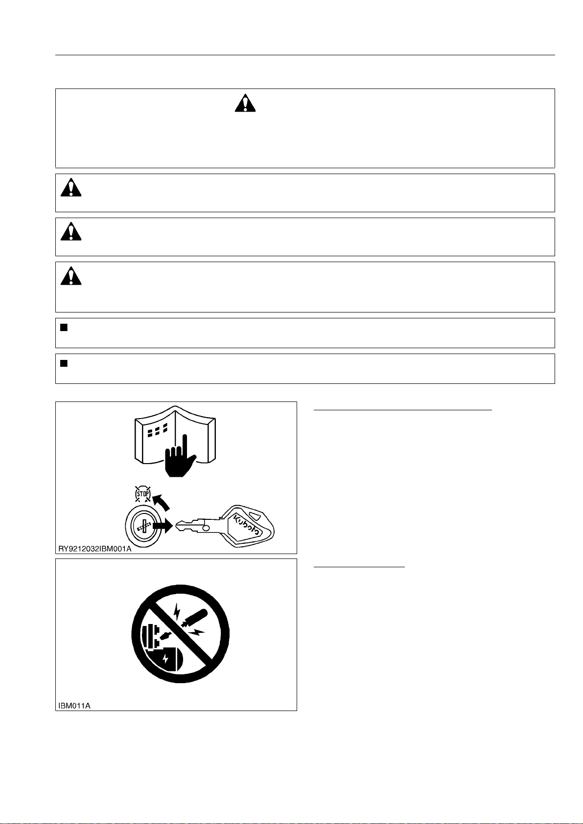
BEFORE SERVICING AND REPAIRING
• Read all instructions and safety instructions in this
manual and on your engine safety decals.
• Clean the work area and engine.
• Park the machine on a stable and level ground.
• Let the temperature of the engine decrease before
you start a job.
• Stop the engine, then remove the key.
• Disconnect the battery negative cable.
• Hang a "DO NOT OPERATE" tag in the operator
station.
RY9212007INI0002US0
SAFETY STARTING
• Do not do the procedures below when you start the
engine.
– short across starter terminals
– bypass the safety start switch
• Do not make unauthorized modifications to the
engine. This can cause damage and decrease the
engine life.
RY9212007INI0003US0
I-1
Page 8
U48-4,U55-4, WSM
KiSC issued 03, 2010 A
INFORMATION
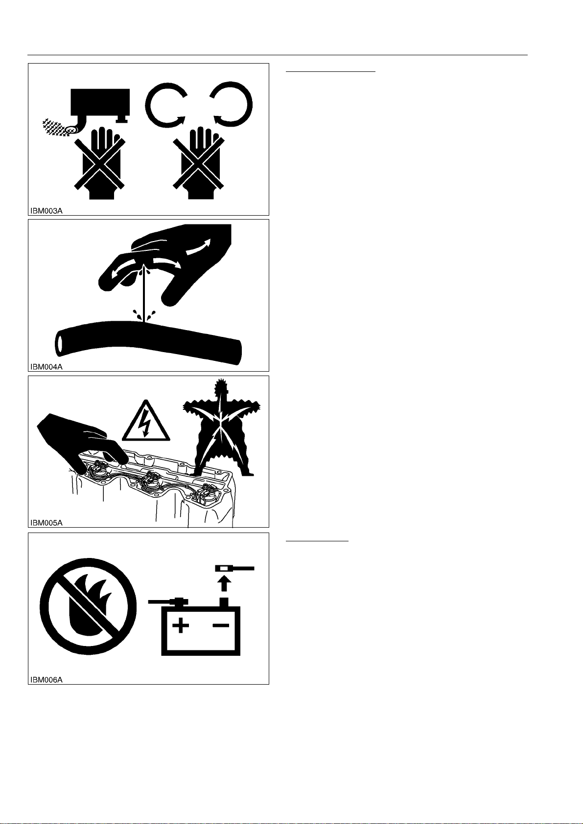
SAFETY WORKING
• Do not use the machine after you consume alcohol
or medication or when you are tired.
• Put on applicable clothing and safety equipment.
• Use applicable tools only. Do not use alternative
tools or parts.
• When 2 or more persons do servicing, make sure
that you do it safely.
• Do not touch the hot parts or parts that turn when the
engine operates.
• Do not remove the radiator cap when the engine
operates, or immediately after it stops. If not, hot
water can spout out from the radiator. Only remove
the radiator cap when it is at a sufficiently low
temperature to touch with bare hands. Slowly loosen
the cap to release the pressure before you remove it
fully.
• Released fluid (fuel or hydraulic oil) under pressure
can cause damage to the skin and cause serious
injury. Release the pressure before you disconnect
hydraulic or fuel lines. Tighten all connections before
you apply the pressure.
• Do not open a fuel system under high pressure.
The fluid under high pressure that stays in fuel lines
can cause serious injury. Do not disconnect or repair
the fuel lines, sensors, or any other components
between the fuel pump and injectors on engines with
a common rail fuel system under high pressure.
• Put on an applicable ear protective device (earmuffs
or earplugs) to prevent injury against loud noises.
• Be careful about electric shock. The engine
generates a high voltage of more than DC100 V in
the ECU and is applied to the injector.
RY9212007INI0004US0
AVOID FIRES
• Fuel is very flammable and explosive under some
conditions. Do not smoke or let flames or sparks in
your work area.
• To prevent sparks from an accidental short circuit,
always disconnect the battery negative cable first
and connect it last.
• The battery gas can cause an explosion. Keep the
sparks and open flame away from the top of battery,
especially when you charge the battery.
• Make sure that you do not spill fuel on the engine.
RY9212007INI0005US0
I-2
Page 9
U48-4,U55-4, WSM
KiSC issued 03, 2010 A
INFORMATION
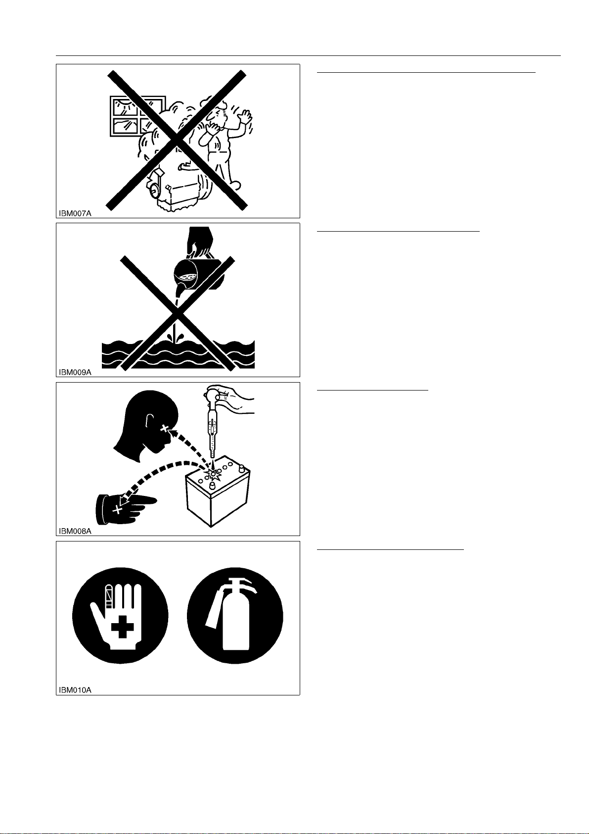
KEEP A GOOD AIRFLOW IN THE WORK AREA
• If the engine is in operation, make sure that the area
has good airflow. Do not operate the engine in a
closed area. The exhaust gas contains poisonous
carbon monoxide.
RY9212007INI0006US0
DISPOSE OF FLUIDS CORRECTLY
• Do not discard fluids on the ground, down the drain,
into a stream, pond, or lake. Obey related
environmental protection regulations when you
discard oil, fuel, coolant, electrolyte and other
dangerous waste.
RY9212007INI0007US0
PREVENT ACID BURNS
• Keep electrolyte away from your eyes, hands and
clothing. Sulfuric acid in battery electrolyte is
poisonous and it can burn your skin and clothing and
cause blindness. If you spill electrolyte on yourself,
clean yourself with water, and get medical aid
immediately.
RY9212007INI0008US0
PREPARE FOR EMERGENCIES
• Keep a first aid kit and fire extinguisher ready at all
times.
• Keep emergency numbers for doctors, ambulance
service, hospital and fire department near your
telephone at all times.
RY9212007INI0009US0
I-3
Page 10
U48-4,U55-4, WSM
KiSC issued 03, 2010 A
INFORMATION
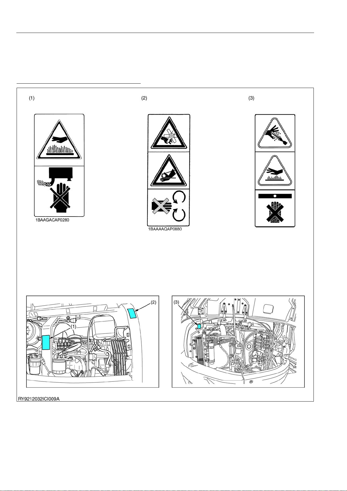
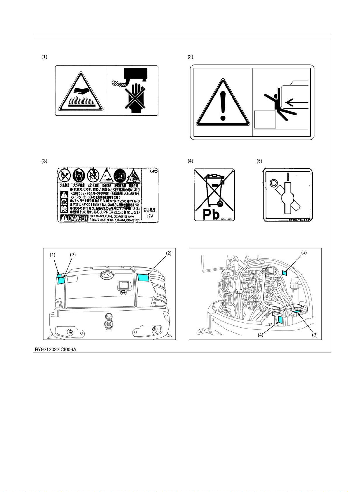
2. SAFETY DECALS
The following safety decals are installed on the machine.
If a decal becomes damaged, illegible or is not on the machine, replace it. The decal part number is listed in
the parts list.
RY9212007INI0010US0
DANGER, WARNING AND CAUTION LABELS
(1) Part No. TA040-49580 - Do not touch hot parts such as exhaust etc.
(2) Part No. RC418-57370 - Keep away from fan and fan belt.
(3) Part No. RA028-57240 - Attention to the danger of burning.
RY9212007INI0011US0
I-4
Page 11
U48-4,U55-4, WSM
KiSC issued 03, 2010 A
INFORMATION
(1) Part No. RD809-57450 - Do not touch hot parts such as exhaust etc.
(2) Part No. RD809-57250 - Do not allow any persons within the working range.
(3) Part No. T1060-30090 - Keep sparks, flame, cigarettes away.
(4) Part No. TD179-30130 - Battery recycle label
(5) Part No. RD359-57840 - Battery cut switch label
RY9212007INI0012US0
I-5
Page 12
U48-4,U55-4, WSM
KiSC issued 03, 2010 A
INFORMATION
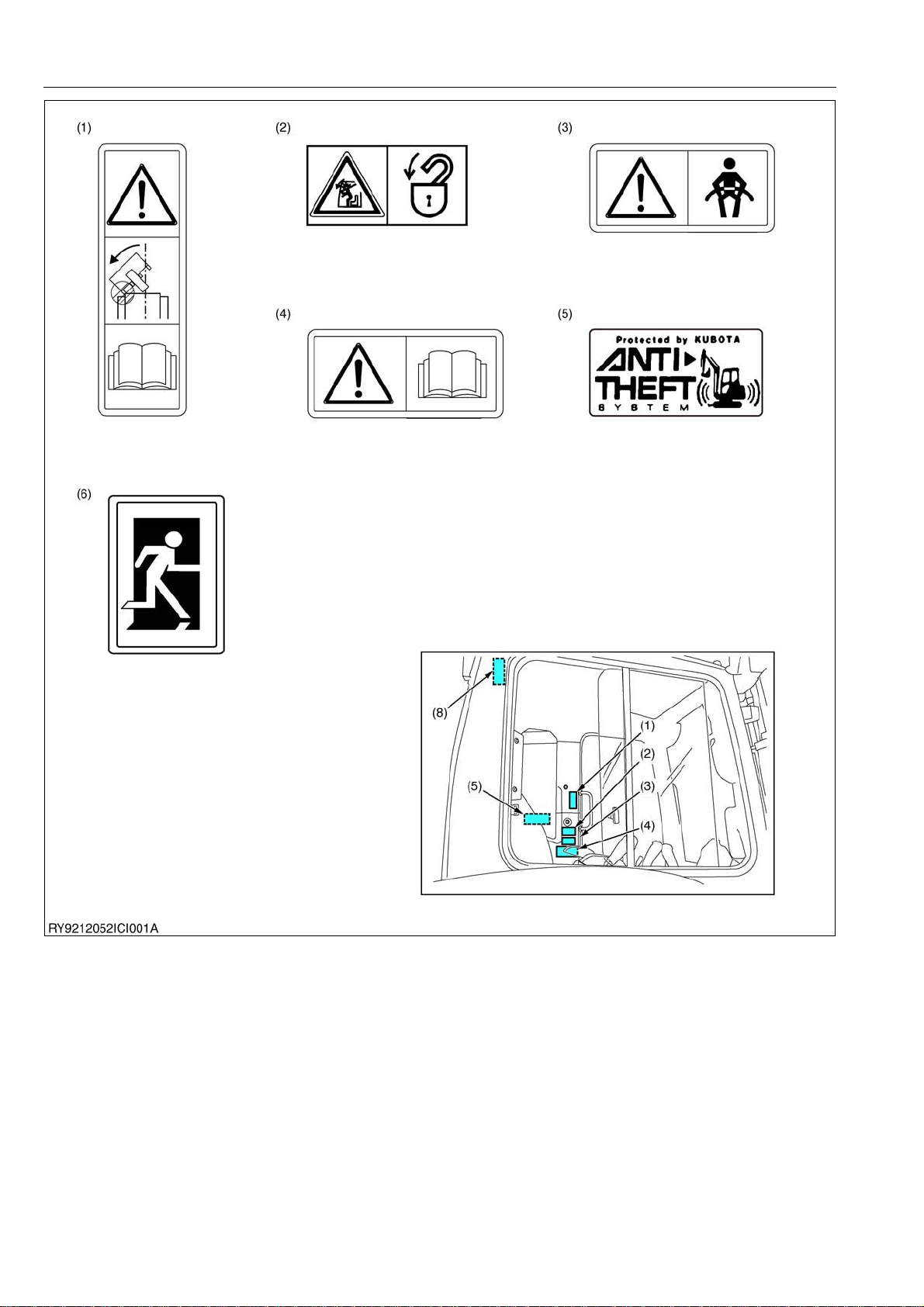
(1) Part No. RD809-57390 - When using a wider or deeper bucket, take good care when swinging or pulling in
(2) Part No. RB419-57930 - Label front door lock
(3) Part No. RD809-57430 - Fasten the seatbelt.
(4) Part No. 69198-57840 - Label manual
(5) Part No. RA228-93380 - Anti-theft system
(6) Part No. RD809-57140 - Emergency exit
the front attachments to make sure that the bucket does not hit the cab.
RY9212052INI0001US0
I-6
Page 13
U48-4,U55-4, WSM
KiSC issued 03, 2010 A
INFORMATION
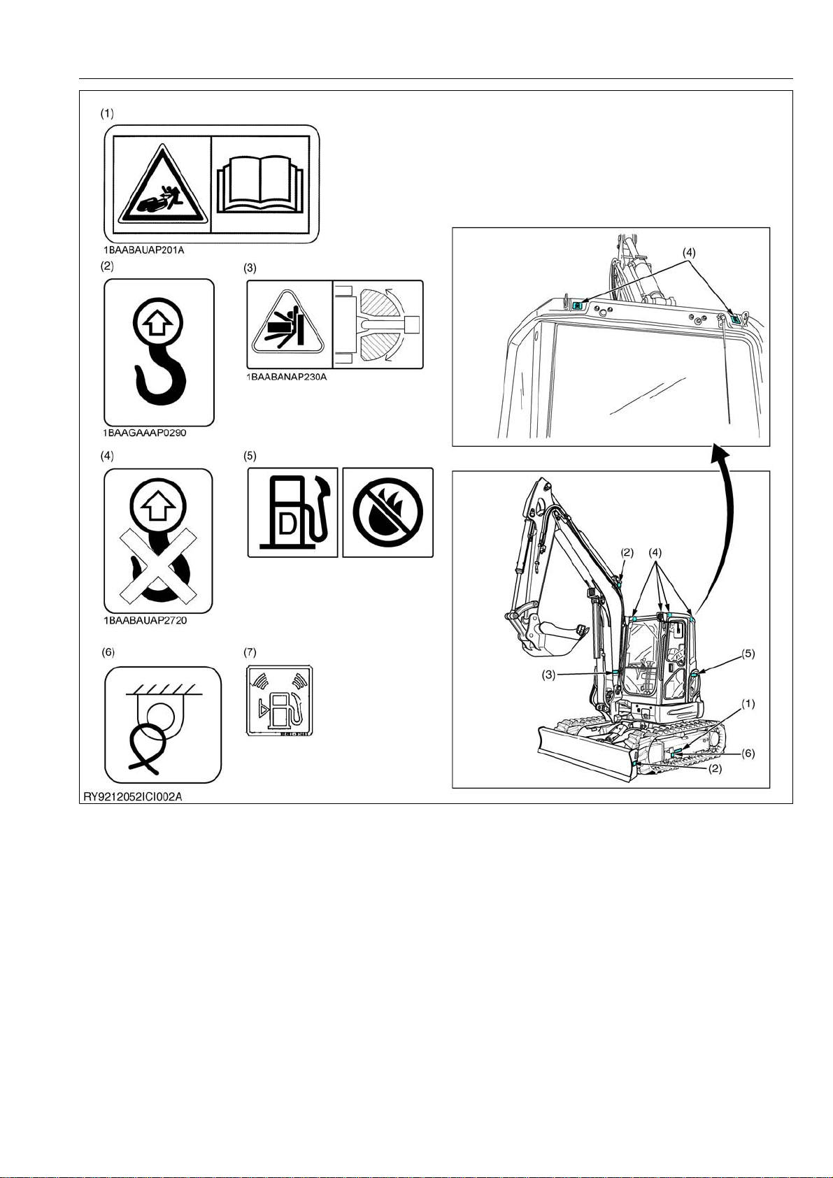
(1) Part No. RD809-57950 - For information about loosening the crawler, consult the operating instructions.
(2) Part No. RC108-57960 - Attachment point for lifting gear.
(3) Part No. RD809-57250 - Do not enter the manoeuvring area.
(4) Part No. RB419-57960 - Not an attachment point for lifting gear!
(5) Part No. RD451-57480 - Diesel fuel only, no open fire.
(6) Part No. RA809-57330 - Use the attachment point only for clamping the excavator securely to a transport
(7) Part No. RD359-57260 - Fuel supply label
vehicle.
RY9212052INI0002US0
I-7
Page 14

U48-4,U55-4, WSM
KiSC issued 03, 2010 A
INFORMATION
CARE OF DANGER, WARNING AND CAUTION LABELS
1. Keep danger, warning and caution labels clean and free from obstructing material.
2. Clean danger, warning and caution labels with soap and water, dry with a soft cloth.
3. Replace damaged or missing danger, warning and caution labels with new labels from your KUBOTA dealer.
4. If a component with danger, warning and caution label(s) affixed is replace with new part, make sure new label(s)
is (are) attached in the same locations(s) as the replace component.
5. Mount new danger, warning and caution labels by applying on a clean dry surface and pressure any bubbles to
outside edge.
RY9212007INI0015US0
I-8
Page 15

G GENERAL
KiSC issued 03, 2010 A
Page 16

GENERAL
KiSC issued 03, 2010 A
CONTENTS
1. CHECKING EXCAVATOR IDENTIFICATION.............................................................................. G-1
2. ENGINE IDENTIFICATION .......................................................................................................... G-2
[1] MODEL NAME AND SERIAL NUMBER ................................................................................ G-2
[2] E3B ENGINE .......................................................................................................................... G-3
[3] CYLINDER NUMBER............................................................................................................. G-3
3. GENERAL PRECAUTIONS.......................................................................................................... G-4
4. HANDLING PRECAUTIONS FOR ELECTRICAL PARTS AND WIRING .................................... G-8
[1] WIRING .................................................................................................................................. G-8
[2] FUSES.................................................................................................................................. G-10
[3] CONNECTOR ...................................................................................................................... G-10
[4] WASHING THE EXCAVATOR WITH A HIGH-PRESSURE WASHER................................ G-11
5. TIGHTENING TORQUES........................................................................................................... G-12
[1] GENERAL USE SCREWS, BOLTS AND NUTS .................................................................. G-12
[2] STUD BOLTS ....................................................................................................................... G-12
[3] TORQUE FOR HYDRAULIC HOSE FITTINGS ................................................................... G-13
(1) Torque for Hydraulic Hose Fittings................................................................................. G-13
(2) Torques of Lock-Nuts for Elbows with Male Seats and Adaptors with O-rings
(Straight Threads)........................................................................................................... G-14
(3) Torque for Tapering Adaptors ........................................................................................ G-14
[4] HOSE CLAMP SCREW TORQUE ....................................................................................... G-15
6. NEW PRODUCT FEATURE (EUROPEAN VERSION) .............................................................. G-17
7. NEW FEATURES OUTLINE....................................................................................................... G-20
8. QUALITY SPECIFICATIONS ..................................................................................................... G-22
9. WATER AND OIL QUANTITY .................................................................................................... G-33
10. DESCRIPTION OF PARTS ........................................................................................................ G-34
[1] BUCKET ............................................................................................................................... G-34
(1) Bucket dimensions ......................................................................................................... G-34
(2) Bucket installation relevant dimensions.......................................................................... G-35
[2] RUBBER CRAWLER............................................................................................................ G-36
[3] STEEL CRAWLER ............................................................................................................... G-36
[4] TRUCK ROLLER, IDLER, SPROCKET ............................................................................... G-37
[5] CYLINDER .......................................................................................................................... G-38
[6] PARTS WEIGHT .................................................................................................................. G-39
11. MAINTENANCE CHECK LIST ................................................................................................... G-41
Page 17
U48-4,U55-4, WSM
KiSC issued 03, 2010 A
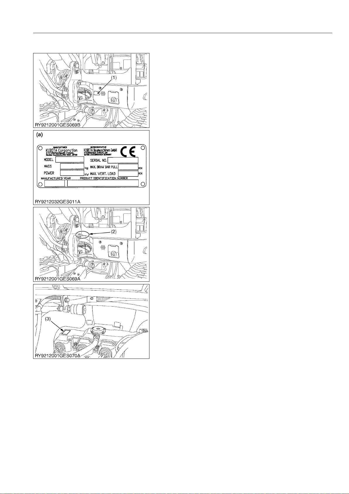
1. CHECKING EXCAVATOR IDENTIFICATION
When consulting with your local KUBOTA dealer about this
mini-excavator, please provide the model of the mini-excavator, its
frame and engine numbers and the number of hours on the hour
meter.
(1) Mini-excavator Nameplate
(Model, frame number, engine
number)
(2) Frame Number
(3) Engine Number
(a) Model Nameplate
RY9212032GEG0003US0
GENERAL
G-1
Page 18

U48-4,U55-4, WSM
KiSC issued 03, 2010 A
2. ENGINE IDENTIFICATION
[1] MODEL NAME AND SERIAL NUMBER
Be sure to check the engine nameplate and serial number when
you wish to consult about the engine.
The model and serial number of the engine need to be checked
prior to servicing the engine or replacing any of its parts.
Q Engine Serial No.
The engine serial number is the numerical ID of the engine and
is printed after the engine's model number.
The year and month of manufacture are indicated as follows
Year Manufactured
Letter or
Number
1 2001 F 2015
2 2002 G 2016
3 2003 H 2017
4 2004 J 2018
5 2005 K 2019
6 2006 L 2020
7 2007 M 2021
8 2008 N 2022
9 2009 P 2023
A 2010 R 2024
B 2011 S 2025
C 2012 T 2026
D 2013 V 2027
E2014
Year
Letter or
Number
GENERAL
Year
*The letters I, O, Q, U and Z are not used.
Month Manufactured
Month Lot Number
January A0001 to A9999 B0001 to BZ999
February C0001 to C9999 D0001 to DZ999
March E0001 to E9999 F0001 to FZ999
April G0001 to G9999 H0001 to HZ999
May J0001 to J9999 K0001 to KZ999
June L0001 to L9999 M0001 to MZ999
July N0001 to N9999 P0001 to PZ999
August Q0001 to Q9999 R0001 to RZ999
September S0001 to S9999 T0001 to TZ999
October U0001 to U9999 V0001 to VZ999
November W0001 to W9999 X0001 to XZ999
December Y0001 to Y9999 Z0001 to ZZ999
*The letter I and O are not used.
(a)
(b)H(c)
(d)
- 8
e.g. V2607
(a) Engine Model : V2607-DI
(b) Year Manufactured : The 8 indicates 2008.
(c) Month : April is indicated by either G or H.
(d) Lot Number : (Either 0001 to 9999 or A001 to Z999)
A001
(1) Engine Model and Serial Number
RY9212001END0009US0
G-2
Page 19
U48-4,U55-4, WSM
KiSC issued 03, 2010 A
GENERAL
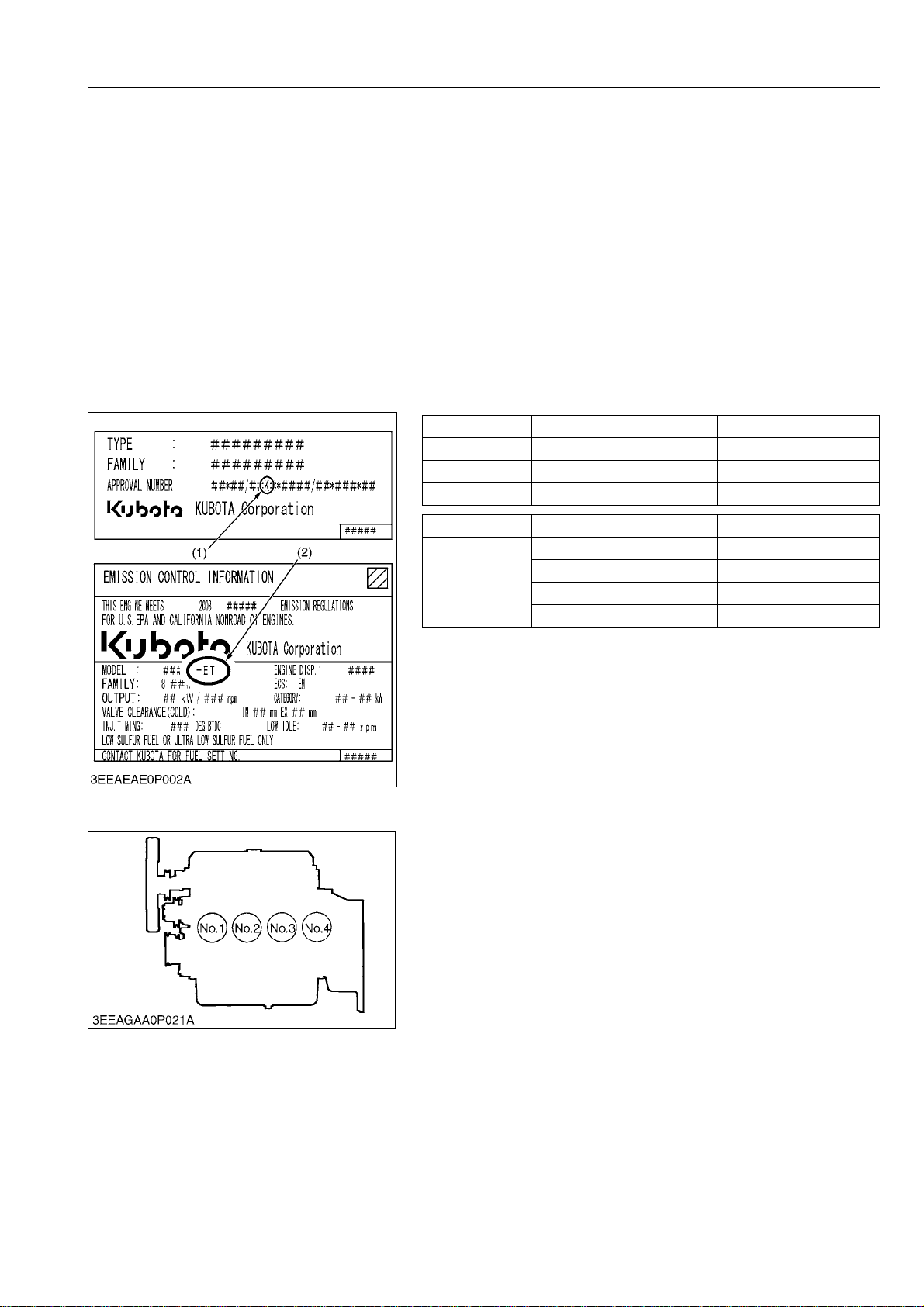
[2] E3B ENGINE
[Ex. : Engine Model V2607-DI-E3B-XXXX]
While the exhaust emissions regulations in each country that have been implemented to date to prevent air
pollution are constantly changing, regulations governing off-road exhaust emissions are expected to be implemented
more quickly. The date that specific off-road exhaust emissions regulations will take effect depends on the output
category of the engine.
For some years now KUBOTA has been supplying regulation-compliant diesel engines in countries where
off-road exhaust emission regulations have been introduced. KUBOTA's E3B series of engines meet the next phase
of exhaust emission regulations. (See the table below.)
Whenever repairs or service is performed on a ###-E3B series engine, E3B engine replacements parts, which
are in the applicable E3B KUBOTA Parts List, must be used and the KUBOTA Operator's Manual and E3B Workshop
Manual must be used for maintenance. Use of incorrect replacement parts or replacement parts from other emission
level engines (for example : E2B engines), may result in emission levels out of compliance with the original E3B
design, EPA and/or other applicable regulations. Check the output category and emissions data on the emissions
label on the header cover of the engine. E3B engines have the suffix ET after the model name on the EPA label. E3B
is not marked on the engine.
Class (1) Engine Output Category EU Regulation
K 19 to/not including 37 kW STAGE IIIA
J 37 to/not including 75 kW STAGE IIIA
I 75 to/not including 130 kW STAGE IIIA
[3] CYLINDER NUMBER
Class (2) Engine Output Category EPA Regulation
Less than 19 kW Tier 4
ET
(1) EU Regulation engine output classification
(2) "E3B engines" have the suffix ET after the model name on the EPA label.
"E3B" models meet Tier 3, Interim Tier4 or Tier4 regulations, depending on the
engine output category.
19 to/not including 56 kW Interim Tier 4
56 to/not including 75 kW Tier 3
75 to/not including 130 kW Tier 3
RY9212001END0010US0
KUBOTA diesel engines are numbered as indicated in the
figure.
Cylinders are numbered from the front cover (fan side) in the
order 1, 2, 3 and 4.
RY9212001END0011US0
G-3
Page 20
U48-4,U55-4, WSM
KiSC issued 03, 2010 A
3. GENERAL PRECAUTIONS
Whenever performing maintenance on the mini-excavator,
always read the Safety Precautions in this manual and the
Operator's Manual carefully, become familiar with them and perform
the work safely.
Before performing any maintenance on the mini-excavator,
make sure it is sufficiently clean and choose a sufficiently clean
location to perform any disassembly.
Before performing maintenance on the mini-excavator, always
disconnect the negative battery cable first.
Whenever a special tool is required, use the special tool that
KUBOTA recommends. Make any special tools that are not used
very frequently according to the diagrams in this manual.
Always use genuine KUBOTA parts to maintain the
performance and safety characteristics of the mini-excavator.
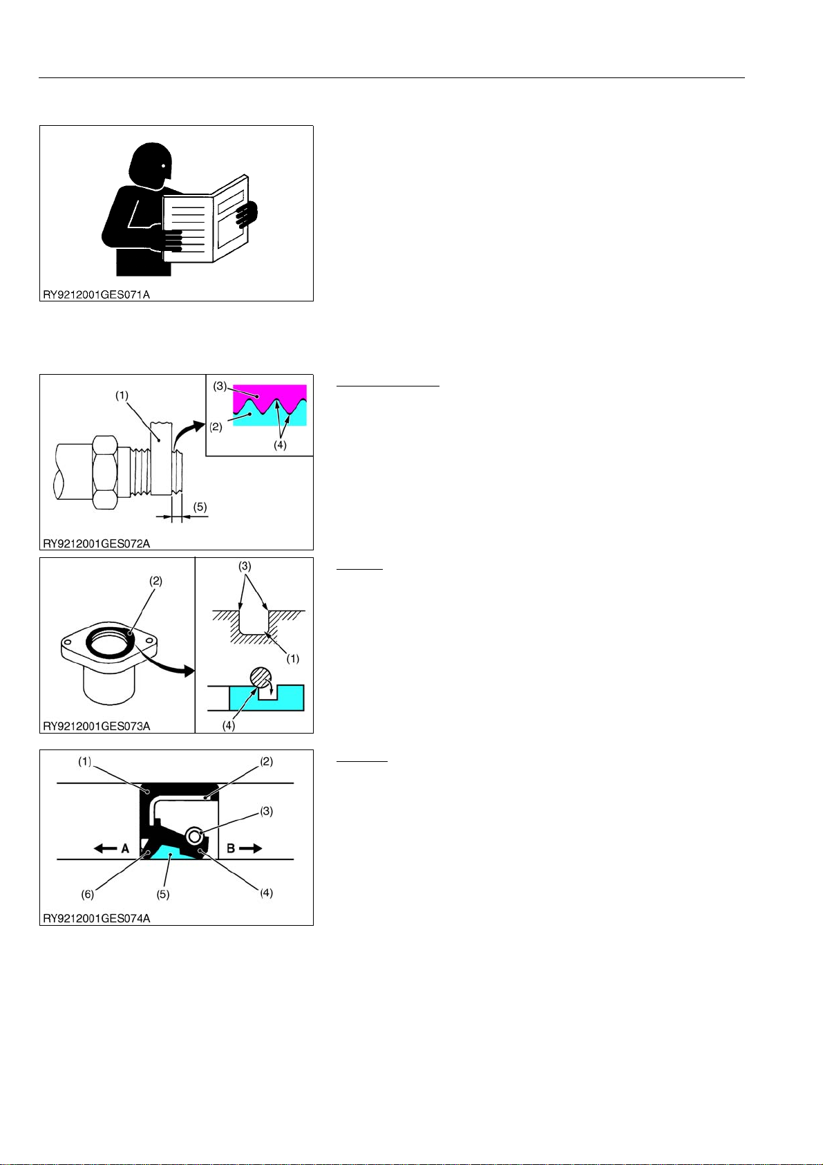
Plumber's Tape
• Wrap plumber's tape on the threads before tightening taper
couplings. After wrapping (2 wraps) the plumber's tape, tighten
to the specified torque. Once the coupling is tightened, do not
loosen it as this will cause an oil leak.
(1) Plumber's Tape
(2) External Thread
(3) Internal Thread
GENERAL
RY9212001GEG0011US0
(4) Gap
(5) Leave 1 to 2 threads
RY9212001GEG0012US0
O-Ring
• Clean the groove the O-ring goes in and remove any burrs.
Apply grease on the O-ring when inserting it in the groove.
(Except floating seals)
• When putting the O-ring in the groove, be careful as it is easy at
the very end to twist the O-ring against the inside of the groove.
If it gets twisted, roll it gently with your fingertip to untwist it.
(1) O-ring Groove
(2) O-ring
(3) Check for burrs
(4) If the ring touches this corner, it will
twist
RY9212001GEG0013US0
Oil Seal
• Do not face the lip of the oil seal in the wrong direction. Face the
main lip toward the material to be sealed.
• After oil seals are replaced, apply grease to the moving parts
around the lip to prevent the dry surfaces from wearing against
each other when the engine is started. If the seal has a dust lip,
fill the gap between the lips with grease.
• As a general rule, use a press to insert the oil seal in place. If
that is not possible, use an appropriate tool to gently and evenly
tap it into place, taking care that it does not go in at a slant.
Press the seal all the way so it seats in the boss.
(1) Gasket
(2) Metal Ring
(3) Spring
(4) Main Lip
(5) Grease
(6) Dust Lip
A : Air (outside)
B : Hydraulic chamber (in side)
RY9212001GEG0014US0
G-4
Page 21
U48-4,U55-4, WSM
KiSC issued 03, 2010 A
GENERAL
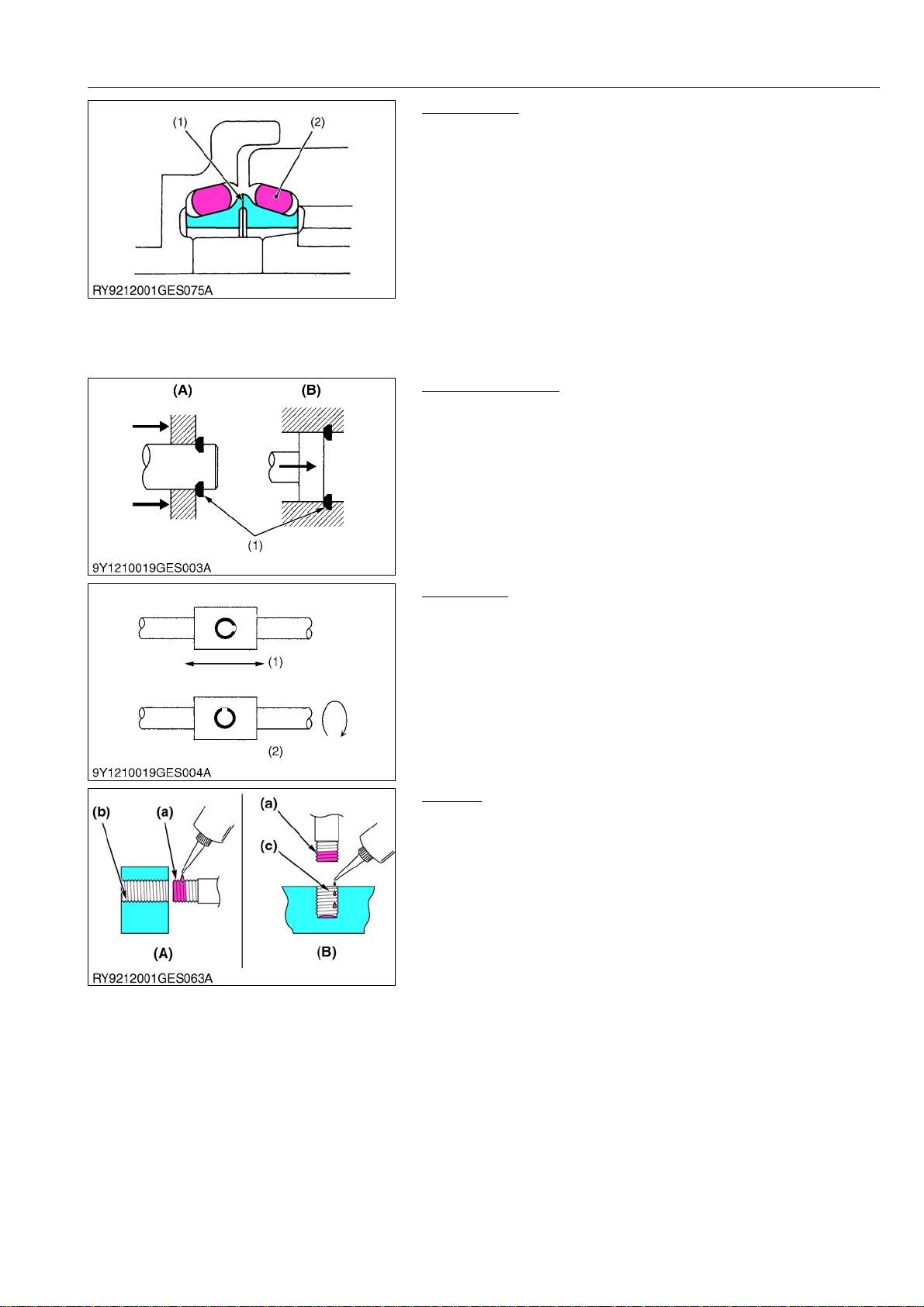
Floating Seal
• Be sure to wipe off any oil from the O-ring or surfaces that touch
the O-ring. (For wheel motors, apply a light film)
• When putting an O-ring into a floating seal, make sure the
O-ring does not twist.
• Apply a light film of oil to surrounding surfaces when working to
get the floating seal with O-ring in place; take care that the
surrounding surfaces, O-ring and housing are parallel with each
other.
• After getting the seal in place, turn the engine over 2 or 3
revolutions, to both create a film of oil on surrounding surfaces
and to properly seat the face of the seal.
(1) Surrounding Surfaces (2) O-ring
RY9212001GEG0015US0
Snap Ring Related
• When installing external or internal snap rings, orient them as
shown in the diagram so the angled side faces the direction of
force.
(1) Position so the angled part receives
the force
(A) External
(B) Internal
RY9212001GEG0016US0
Spring Pins
• When driving a spring pin, face the split in the direction that
receives the force, as shown in the diagram.
(1) With lateral movement (2) With rotational movement
RY9212001GEG0017US0
Locktite
• Clean and dry the area where Locktite will be applied with a
solvent so it is free of moisture, oil and dirt.
• Apply locktite all around the threads of the bolt except the first
set of threads at the tip and fill the grooves between the threads.
If the threads or the grooves are large, adjust the amount of
locktite accordingly and apply it all around the bolt hole as well.
(A) Bolt Through-hole (nut)
(B) Pocket Bolt Hold
(capsule shape, etc.)
(a) Apply here
(b) Do not apply
(c) Drip on
RY9212001GEG0018US0
G-5
Page 22
U48-4,U55-4, WSM
KiSC issued 03, 2010 A
GENERAL
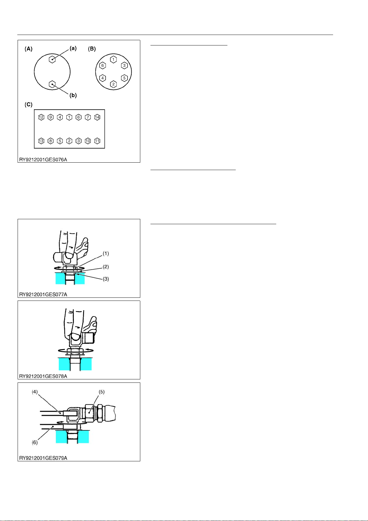
Tightening Bolts and Nuts
• Tighten bolts and nuts to their specified torque.
• Tighten nuts and bolts alternately top/bottom (a) (b), left/right so
the torque is distributed evenly.
(A) Top/bottom alternately
(B) Across diagonally
(C) Diagonally across the center
RY9212001GEG0019US0
Assembling Hydraulic Hoses
• Tighten to their specified torque.
• Before assembling, wipe the inside of metal fittings clean of any
dirt.
• After assembly, put the fitting under normal pressure and check
that it does not leak.
RY9212001GEG0020US0
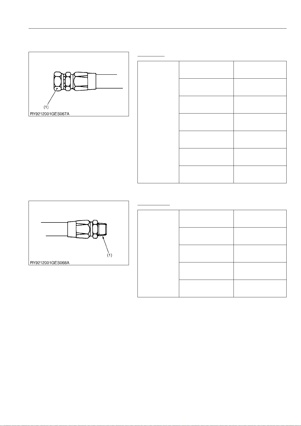
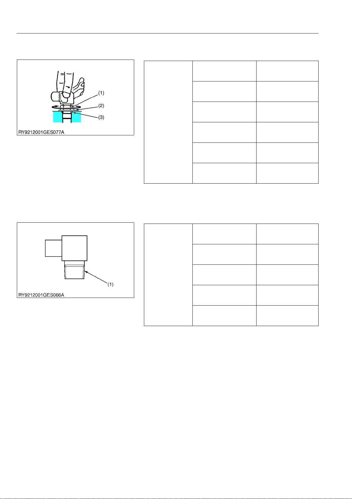
Elbow with Male Seat Assembly Procedure
When assembling an elbow with male seat, adhere to the
following procedures to prevent deformation of O-rings and leaks.
1. Connecting to Valves
• Clean the blow with male seat and the surface of the seal
opposite and mount with the lock-nut on top.
• Finger tighten till it touches the washer.
2. Positioning
• Turn the mouth of the elbow back so it faces the right
direction. (not back over 1 turn)
3. Fasten
• Tighten the lock-nut to the specified torque with a wrench.
(1) Lock-nut
(2) Washer
(3) Seal (O-ring)
(4) Wrench for holding
(5) Hose
(6) Torque wrench for tightening
RY9212001GEG0021US0
G-6
Page 23

U48-4,U55-4, WSM
KiSC issued 03, 2010 A
GENERAL
Installing and Removing Quick Couplings
• To remove a quick hose coupling, push the fitting (2) in the
direction of the arrow and pull on the plastic part (1) in the
opposite direction.
• To attach a quick coupler, push it in firmly in the direction of the
arrow. Then check that it will not pull off.
(1) Plastic part (2) Fitting
RY9212001GEG0022US0
G-7
Page 24
U48-4,U55-4, WSM
IMPORTANT
KiSC issued 03, 2010 A
GENERAL
4. HANDLING PRECAUTIONS FOR ELECTRICAL
PARTS AND WIRING
Follow the precautions below for handling electrical parts and
wiring to ensure safety and prevent damage to the mini-excavator
and nearby equipment.
• Inspect electrical wiring for damage and/or loose
connections.
• Do not alter or rewire any electrical parts or wiring.
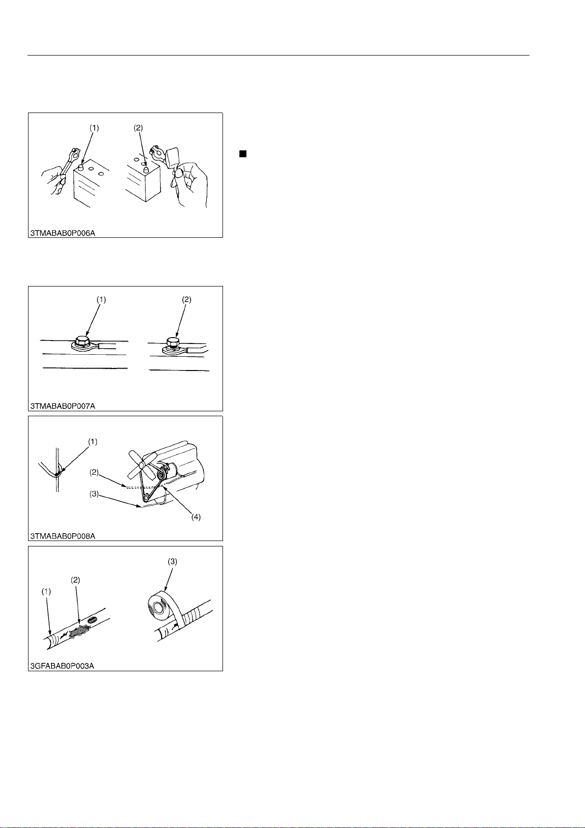
• Always remove the negative battery cable first when
disconnecting the battery and attach the p ositive cable first
when connecting it.
(1) Battery Cable (-) Side (2) Battery Cable (+) Side
RY9212001GEG0023US0
[1] WIRING
• Tighten wiring terminals securely.
(1) Correct (Tightened securely) (2) Incorrect (Poor contact if loose)
RY9212001GEG0024US0
• Keep wiring away from hazards.
(1) Hazardous Positioning
(2) Wiring Position (wrong)
(3) Wiring Position (right)
(4) Hazardous Position
RY9212001GEG0025US0
• Immediately repair or replace old or damaged wiring.
(1) Damaged
(2) Torn
(3) Electrical Tape
RY9212001GEG0026US0
G-8
Page 25
U48-4,U55-4, WSM
KiSC issued 03, 2010 A
GENERAL
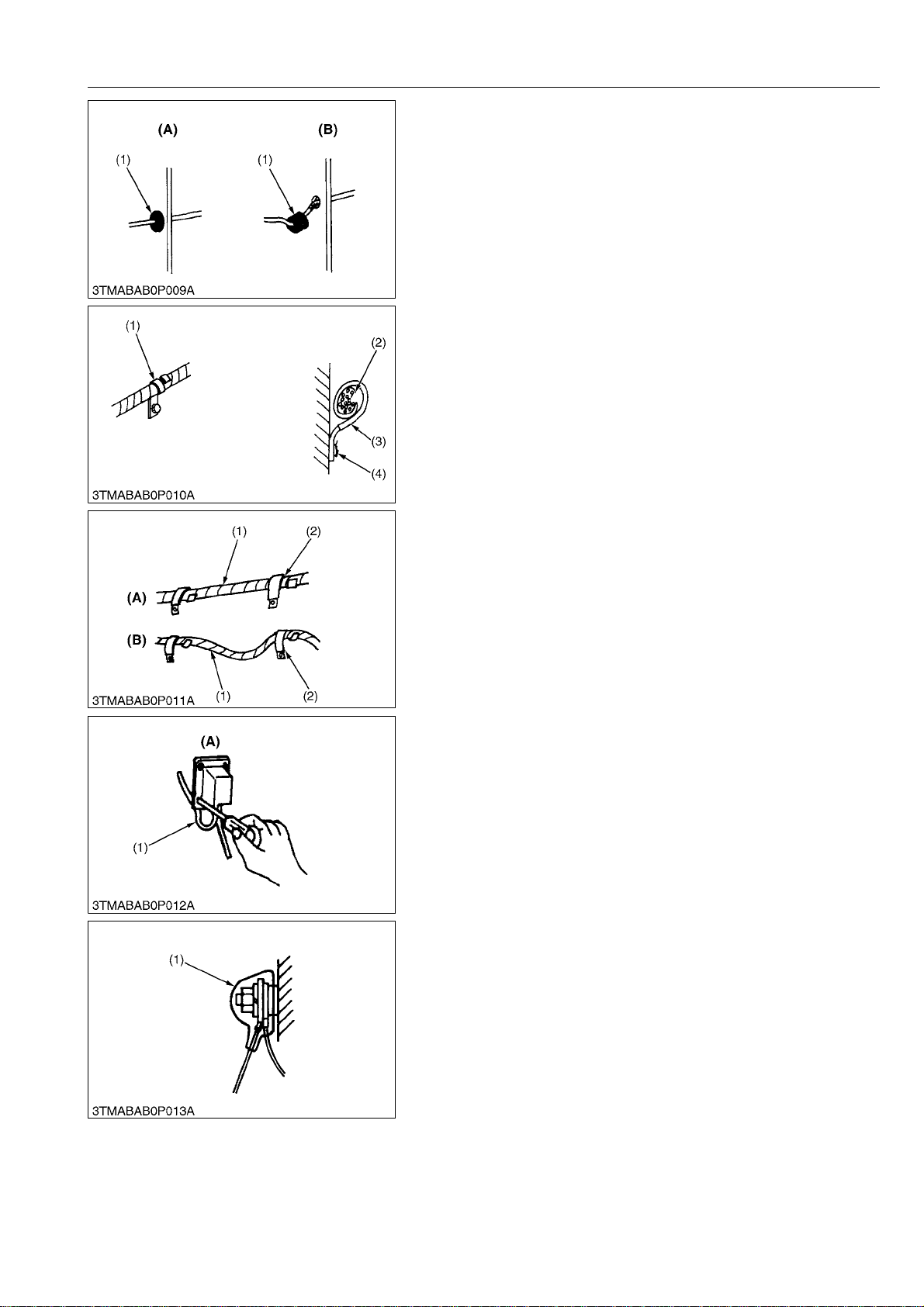
• Insert grommet securely.
(1) Grommet (A) Correct
(B) Incorrect
RY9212001GEG0027US0
• Clamp wiring securely but do not damage wires with the clamp.
(1) Clamp (Spiral clamp around wire)
(2) Wire
(3) Clamp
(4) Welding Mark
RY9212001GEG0028US0
• Clamp wiring so it is not twisted, pulled too tight or sag too
much. However, moving parts may require play in the wiring.
(1) Wire
(2) Clamp
(A) Correct
(B) Incorrect
RY9212001GEG0029US0
• Do not pinch or bind wiring when installing parts.
(1) Wire (A) Incorrect
RY9212001GEG0030US0
• After wiring, double-check terminal protectors and clamps
before connecting battery cables.
(1) Cover (Install covers securely)
RY9212001GEG0031US0
G-9
Page 26
U48-4,U55-4, WSM
KiSC issued 03, 2010 A
[2] FUSES
[3] CONNECTOR
GENERAL
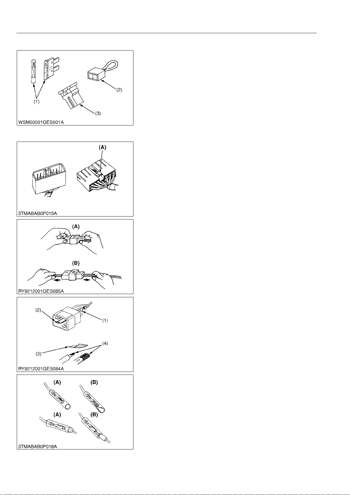
• Always use fuses of the specified capacity.
Never use over or undersized fuses.
• Never use copper or steel wire in place of a fuse.
• Do not install accessories such as work lights, radios, etc., if
your mini-excavator does not have an auxiliary circuit.
• Do not install accessories as they will exceed the capacity of
fuses.
(1) Fuse
(2) Fusible Link
(3) Slow-blow Fuse
RY9212001GEG0032US0
• Press the lock to disconnect locking connectors.
(A) Push
RY9212001GEG0033US0
• Hold the connectors when separating them.
• Do not pull on the wire harness to separate the connectors.
(A) Correct (B) Incorrect
RY9212001GEG0034US0
• Straighten bent prongs and make sure none are sticking out or
missing.
• Remove corrosion from terminals with sandpaper.
(1) Missing terminal
(2) Bent Prong
(3) Sandpaper
(4) Corrosion
RY9212001GEG0035US0
• Female connectors must not be spread too far open
(A) Correct (B) Incorrect
RY9212001GEG0036US0
G-10
Page 27
U48-4,U55-4, WSM
CAUTION
KiSC issued 03, 2010 A
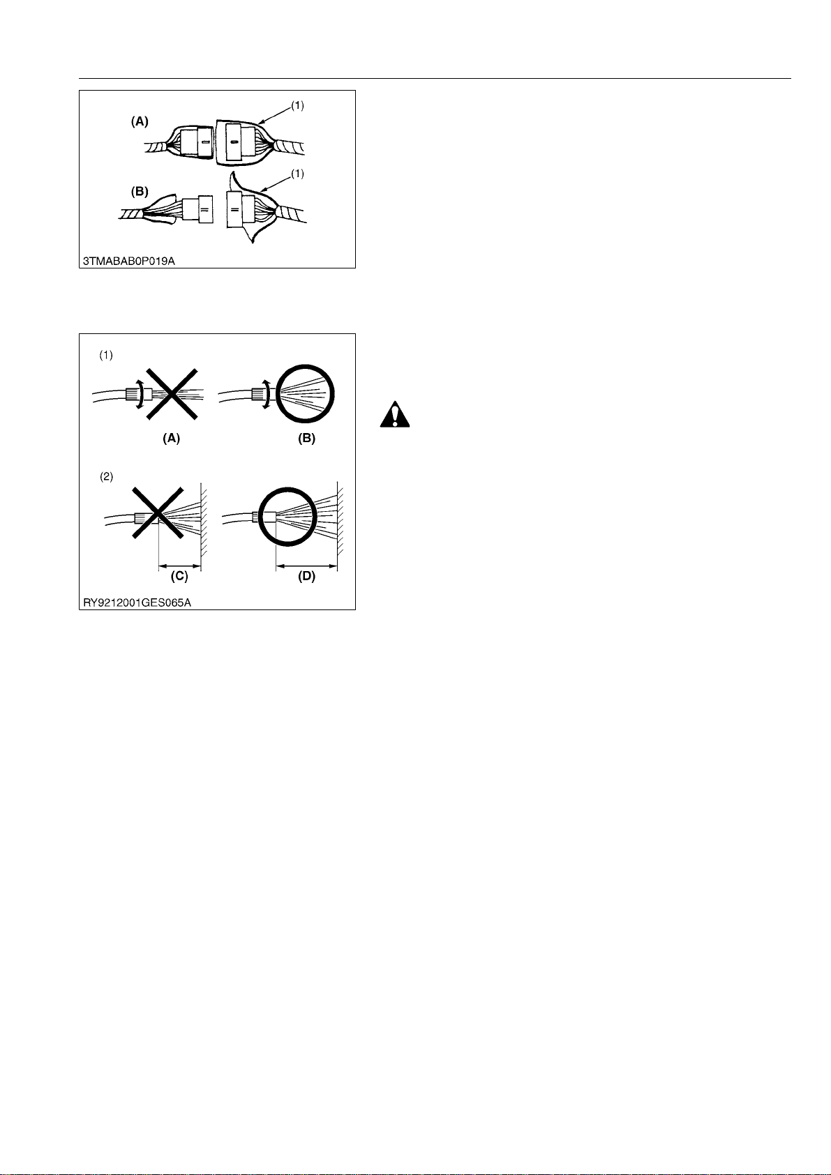
• The plastic covers of connectors must cover them completely.
(1) Cover (A) Correct
(B) Incorrect
RY9212001GEG0037US0
[4] WASHING THE EXCAVATOR WITH A HIGH-PRESSURE
WASHER
Using a high-pressure washer incorrectly can lead to personal
injury and/or damage, break or cause parts of the mini-excavator to
fail, so use the power washer properly according to its user's
manual and labels.
• Stand at least 2 meters from the mini-excavator and adjust
the nozzle for a wide spray so it does not cause any
damage. If you blast the mini-excavator wit h wa ter or wash
it from too close a distance,
1. It may cause a fire due to damaged or cu ts in the insulation
of electrical wiring.
2. An injury may result if hydraulic oil gushes out under high
pressure, due to damaged hydraulic hoses.
3. It may damage, break or cause parts of the mini-excavator
to fail.
(Ex.)
(1) Stickers or labels may come off
(2) Electrical parts or the engine may fail due to water in them.
(3) Damage glass, resins, etc. or the rubber of oil seals.
(4) Tear off paint or the film from plating
(1) Do not blast with water
(2) Never wash from too close
(A) Blasting
(B) Wide Spray
(C) Less than 2 m (80 in.)
(D) Over 2 m (80 in.)
RY9212001GEG0038US0
GENERAL
G-11
Page 28

U48-4,U55-4, WSM
KiSC issued 03, 2010 A
GENERAL
5. TIGHTENING TORQUES
[1] GENERAL USE SCREWS, BOLTS AND NUTS
Screws, bolts and nuts whose tightening torques are not specified in this Workshop Manual should be
tightened according to the table b elow .
Indication on top of bolt
Indication on top of nut
Material of opponent part Ordinariness Aluminum Ordinariness Aluminum Ordinariness
Unit N·m kgf·m lbf·ft N·m kgf·m lbf·ft N·m kgf·m lbf·ft N·m kgf·m lbf·ft N·m kgf·m lbf·ft
7.9
0.80
M6
M8
M10
M12
M14
M16
M18
M20
to
9.3
18
to
20
40
to
45
63
to
72
108
to
125
167
to
191
246
to
284
334
to
392
to
0.95
1.8
to
2.1
4.0
to
4.6
6.4
to
7.4
11. 0
to
12.8
17.0
to
19.5
25.0
to
29.0
34.0
to
40.0
No-grade or 4T 7T 9T
No-grade or 4T
5.8
7.9
0.80
5.8
9.81
1.00
7.24
7.9
0.80
5.8
to
to
to
1.7
to
2.0
3.2
to
3.5
to
6.5
13
to
14
24
to
25
6.8
8.8
0.90
13
17
to
to
15
19
32
29
to
to
33
34
47
to 53–––
79.6
to
92.5
–––
123
to
–––
141
181
to
–––
209
246
to
–––
289
to
11. 2
24
to
27
48
to
55
78
to
90
124
to
147
197
to
225
275
to
318
368
to
431
to
1.15
2.4
to
2.8
4.9
to
5.7
7.9
to
9.2
12.6
to
15.0
20.0
to
23.0
28.0
to
32.5
37.5
to
44.0
to
8.31
18
to
20
36
to
41
58
to
66
91.2
to
108
145
to
166
203
to
235
272
to
318
to
to
8.8
0.90
18
1.8
to
to
20
2.1
40
4.0
to
to
44
4.5
63
6.4
to
to
72
7.4
––
–––
–––
–––
12.3
to
to
6.5
14.2
13
30
to
to
15
34
29
61
to
to
32
70
47
103
to
to
53
117
167
–
to
196
260
to
304
344
to
402
491
to
568
RY9212032GEG0001US0
6T
1.25
to
1.45
3.0
to
3.5
6.2
to
7.2
10.5
to
12.0
17.0
to
20.0
26.5
to
31.0
35.0
to
41.0
50.0
to
58.0
9.05
to
10.4
22
to
25
45
to
52
76.0
to
86.7
123
to
144
192
to
224
254
to
296
362
to
419
[2] STUD BOLTS
Material of opponent part Ordinariness Aluminum
Unit N·m kgf·m lbf·ft N·m kgf·m lbf·ft
12
1.2
8.7
M8
M10
M12
M14
M16
M18
to
15
25
to
31
30
to
49
62
to
73
98.1
to
112
172
to
201
to
1.6
2.5
to
3.2
3.0
to
5.0
6.3
to
7.5
10.0
to
11. 5
17.5
to
20.5
8.9
to
to
11
11
18
20
to
to
23
25
22
to 3631 3.2 23
46
to 54–––
72.4
to
83.1
–––
127
to
–––
148
0.90
to
1.2
2.0
to
2.6
6.5
to
8.6
15
to
18
RY9212032GEG0002US0
G-12
Page 29
U48-4,U55-4, WSM
KiSC issued 03, 2010 A
[3] TORQUE FOR HYDRAULIC HOSE FITTINGS
(1) Torque for Hydraulic Hose Fittings
Union Nuts
GENERAL
Torque
(1) Union Nuts
Tapered Nuts
1/8
1/4
3/8
1/2
3/4
1
1-1/4
7.8 to 11.8 N·m
0.8 to 1.2 kgf·m
5.7 to 8.7 lbf·ft
24.5 to 29.2 N·m
2.5 to 3.0 kgf·m
18.1 to 21.7 lbf·ft
37.2 to 42.1 N·m
3.8 to 4.3 kgf·m
27.5 to 31.1 lbf·ft
58.8 to 63.7 N·m
6.0 to 6.5 kgf·m
43.4 to 47.0 lbf·ft
117.6 to 127.4 N·m
12.0 to 13.0 kgf·m
86.8 to 94.0 lbf·ft
181.3 to 191.1 N·m
18.5 to 19.5 kgf·m
133.8 to 141.0 lbf·ft
220.5 to 230.3 N·m
22.5 to 23.5 kgf·m
162.8 to 170.0 lbf·ft
RY9212001GEG0041US0
Torque
(1) Taper
1/8
1/4
3/8
1/2
3/4
19.6 to 29.4 N·m
2.0 to 3.0 kgf·m
14.5 to 21.7 lbf·ft
36.6 to 44.1 N·m
3.7 to 4.5 kgf·m
26.8 to 32.5 lbf·ft
68.6 to 73.5 N·m
7.0 to 7.5 kgf·m
50.6 to 54.2 lbf·ft
83.4 to 88.3 N·m
8.5 to 9.0 kgf·m
61.5 to 65.1 lbf·ft
166.6 to 181.3 N·m
17.0 to 18.5 kgf·m
123.0 to 133.8 lbf·ft
RY9212001GEG0042US0
G-13
Page 30
U48-4,U55-4, WSM
KiSC issued 03, 2010 A
GENERAL
(2) Torques of Lock-Nuts for Elbows with Male Seats and Adaptors with
O-rings (Straight Threads)
(1) Lock-nut
(2) Washer
(3) Torque for Tapering Adaptors
Torque
Torque
1/8
1/4
3/8
1/2
3/4, 1
1-1/4
(3) Seal (O-ring)
1/8
1/4
3/8
1/2
3/4
15.0 to 16.5 N·m
1.5 to 1.7 kgf·m
11.1 to 12.2 lbf·ft
24.5 to 29.4 N·m
2.5 to 3.0 kgf·m
18.1 to 21.7 lbf·ft
49.0 to 53.9 N·m
5.0 to 5.5 kgf·m
36.1 to 39.8 lbf·ft
58.8 to 63.7 N·m
6.0 to 6.5 kgf·m
43.4 to 47.0 lbf·ft
117.6 to 127.4 N·m
12.0 to 13.0 kgf·m
86.8 to 94.0 lbf·ft
220.5 to 230.3 N·m
22.5 to 23.5 kgf·m
162.8 to 170.0 lbf·ft
RY9212001GEG0043US0
19.6 to 29.4 N·m
2.0 to 3.0 kgf·m
14.5 to 21.7 lbf·ft
36.6 to 44.1 N·m
3.7 to 4.5 kgf·m
26.8 to 32.5 lbf·ft
68.6 to 73.5 N·m
7.0 to 7.5 kgf·m
50.6 to 54.2 lbf·ft
83.4 to 88.3 N·m
8.5 to 9.0 kgf·m
61.5 to 65.1 lbf·ft
166.6 to 181.3 N·m
17.0 to 18.5 kgf·m
123.0 to 133.8 lbf·ft
(1) Taper
RY9212001GEG0044US0
G-14
Page 31

U48-4,U55-4, WSM
KiSC issued 03, 2010 A
[4] HOSE CLAMP SCREW TORQUE
Type 1
Torque
10- 14 6C040-58721
12- 16 09318-89016
19- 25 09318-89024
31- 40 09318-89039
36- 46 09318-89045
44- 53 09318-89052
51- 59 09318-89058
86- 96 RD809-42241
GENERAL
2.5 to 3.4 N·m
25 to 35 kgf·cm
1.8 to 2.5 lbf·ft
2.5 to 3.4 N·m
25 to 35 kgf·cm
1.8 to 2.5 lbf·ft
2.5 to 3.4 N·m
25 to 35 kgf·cm
1.8 to 2.5 lbf·ft
2.5 to 3.4 N·m
25 to 35 kgf·cm
1.8 to 2.5 lbf·ft
2.5 to 3.4 N·m
25 to 35 kgf·cm
1.8 to 2.5 lbf·ft
3.9 to 4.9 N·m
40 to 50 kgf·cm
2.9 to 3.6 lbf·ft
3.9 to 4.9 N·m
40 to 50 kgf·cm
2.9 to 3.6 lbf·ft
3.9 to 4.9 N·m
40 to 50 kgf·cm
2.9 to 3.6 lbf·ft
RY9212001GEG0045US0
G-15
Page 32

U48-4,U55-4, WSM
KiSC issued 03, 2010 A
Type 2
Torque
13- 20 RB101-63631
15- 25 RC101-64581
19- 28 R1401-63211
22- 32 R1401-63151
26- 38 68311-72821
32- 44 RD411-63821
44- 56 35820-15181
50- 65 RC401-63191
58- 75 36919-04591
60- 80 RD809-63101
68- 85 RD809-63061
77- 95 69284-63171
GENERAL
2.5 to 3.4 N·m
25 to 35 kgf·cm
1.8 to 2.5 lbf·ft
4.9 to 5.9 N·m
50 to 60 kgf·cm
3.6 to 4.3 lbf·ft
4.9 to 5.9 N·m
50 to 60 kgf·cm
3.6 to 4.3 lbf·ft
4.9 to 5.9 N·m
50 to 60 kgf·cm
3.6 to 4.3 lbf·ft
4.9 to 5.9 N·m
50 to 60 kgf·cm
3.6 to 4.3 lbf·ft
4.9 to 5.9 N·m
50 to 60 kgf·cm
3.6 to 4.3 lbf·ft
4.9 to 5.9 N·m
50 to 60 kgf·cm
3.6 to 4.3 lbf·ft
4.9 to 5.9 N·m
50 to 60 kgf·cm
3.6 to 4.3 lbf·ft
4.9 to 5.9 N·m
50 to 60 kgf·cm
3.6 to 4.3 lbf·ft
4.9 to 5.9 N·m
50 to 60 kgf·cm
3.6 to 4.3 lbf·ft
4.9 to 5.9 N·m
50 to 60 kgf·cm
3.6 to 4.3 lbf·ft
4.9 to 5.9 N·m
50 to 60 kgf·cm
3.6 to 4.3 lbf·ft
RY9212001GEG0046US0
G-16
Page 33

U48-4,U55-4, WSM
KiSC issued 03, 2010 A
GENERAL
6. NEW PRODUCT FEATURE (EUROPEAN VERSION)
Quick chart - Machine type classification should be defined (L type)
Basic specification Operation
Robust Machine Weight (Machine class
(1)
upgraded to 5.5 ton)
(2) V2607 New DI Engine Serviceability
(3) Advanced Three Pump Load Sensing System * (14) Sheet-metal processed covers
(4) Strong bucket breakout force (15) One side engine maintenance
Performance (16) Bush with flange at arm tip end
(5) Bigger Lifting Capacity (17)
Dual Speed with Auto-shift as standard
(6)
(Bigger travel force)
(7) Higher Blade (18) Travel parking brake as standard
Shortened distance between blade and bucket
(8)
teeth
Operator comfort (19) KUBOTA original digital panel at the Front *
(9) Spacious and comfort cabin (20)
(10) Powerful Air conditioning (21) Battery Isolator *
Versatility
(11)
(12)
* : New Feature
AUX1" and "AUX2" with proportional control on
joystick is adopted. *
The maximum oil flow of both AUX lines can be
adjusted by digital panel. *
(13)
Safety
Others
Pilot hydraulic remote-control system for all
actuators
Prolonged return filter life 500 hours
→ 1000 hours
Leading-edge Anti-theft system for greater
security
RY9212052GEG0001US0
G-17
Page 34

U48-4,U55-4, WSM
KiSC issued 03, 2010 A
Standard Equipment
Safety system
• Engine start safety system on the left console
• Travel motor with disc brake
• Swivel motor with disc brake
• Overload warning buzzer
• KUBOTA original anti-theft system
• Anti-drop valve on the boom (ISO8643)
Working equipment
• Auxiliary hydraulic circuits (SP1 and SP2*) piping to the arm end *for Types L and M.
• 2 working lights on cabin and 1 light on the boom
• 1450 mm arm length (U48-4)
• 1570 mm arm length (U55-4)
Cabin
• ROPS (Roll-over Protective Structure, ISO3471)
• OPG (Operating Protective Guard) Level1
• Wight-adjustable full suspension seat
• Seatbelt
• Hydraulic pilot control levers with wrist rests
• Travel levers with foot pedals
• Air conditioning (Type L)
• Cabin heater for defrosting and demising
• Emergency exit hammer
• Front window power assisted with gas damper
• 12 V power source
• 2 speakers and radio aerial
• Location for radio
• Back mirror (left, right and rear)
• Cup holder
Engine / Fuel system
• Double-element air filter
• Electric fuel injection pump system
• Auto idling system
Undercarriage
• 400 mm rubber track
• 1 x upper track roller
• 5 double-flange track rollers on each track
• 2-speed travel switch on blade lever
• Two-speed travel with auto-shift
• Water separator with drain cock
Hydraulic system
• Pressure accumulator
• Hydraulic pressure checking ports
• Straight travel circuit
• Third line hydraulic return
• Load-sensing hydraulic system
• Adjustable maximum oil flow on auxiliary circuits (SP1 and SP2) *For (Type L and M)
• Double auxiliary circuit accessories
• Auxiliary switch (SP1) on right control lever
• Auxiliary switch (SP2) on left control lever (Type L and M)
GENERAL
RY9212052GEG0002US0
G-18
Page 35

U48-4,U55-4, WSM
KiSC issued 03, 2010 A
Optional Equipment
Undercarriage
• 400 mm steel track (+ 100 kg)
• 550 mm steel track (+ 300 kg)
Safety system
• Anti-drop valve unit (arm and blade)
• Bracket and harness for beacon light
Others
• Special paint upon request
Standard Equipment For Each Type
GENERAL
RY9212007GEG0003US0
Type
L OO / O
M – O / O
S – O / –
Air
conditioning
AUX1 / AUX2
SP
RY9212052GEG0003US0
G-19
Page 36

U48-4,U55-4, WSM
KiSC issued 03, 2010 A
7. NEW FEATURES OUTLINE
New Design Digital Meter Panel
Features :
1. Large LCD display
2. Display and anti-theft controllers are unified into 1 ECU.
3. Main display and ECU are independent items connected by
CAN (Controller Area Network) technology.
(1) GENERAL
*CONTROL ECU
*AUTO IDLE
*ANTI-THEFT
*AUTO SHIFT TRAVELING SPEED
AUX 1 and 2 Operation Control
Hard-control system
The hydraulic control grip has proportional Flow Control built in.
Signals from this sensor activate the proportional solenoid valve to
control the flow rate at the hydraulic service port.
(1) Control knob (Auxiliary circuit)
GENERAL
(2) MAIN DISPLAY METER PANAL
(a) CAN
RY9212007GEG0005US0
RY9212007GEG0006US0
Battery Isolator
(1) Battery cut switch (a) "ON"
(b) "OFF"
RY9212007GEG0007US0
G-20
Page 37

U48-4,U55-4, WSM
KiSC issued 03, 2010 A
Three pump Load Sensing System
Hydraulic operation for all actuators
All actuators are hydraulically locked when the unlock lever is raised.
(travel, swing, blade and AUX are also hydraulically controlled.)
It realizes smoother movement with fine inching control.
3-pump load sensing system
• U55-4 adopts the same 3-pump load sensing system as
KX057-4.
• 1st and 2nd pumps that normally supply the oil to front
attachments change the oil flow to travel actuator when
travelling in order to realize the strong travel performance.
• The travel slow down while operating front attachments is
minimized by adopting 3-pump load sensing system (ex. when
blading and travelling.
(1) Travel (R), Travel (L)
(2) Boom, Arm, Bucket, AUX1, Swivel
(3) AUX2, Blade, Swing
GENERAL
(A) When not travelling
(B) When travelling
RY9212052GEG0004US0
G-21
Page 38

U48-4,U55-4, WSM
KiSC issued 03, 2010 A
GENERAL
8. QUALITY SPECIFICATIONS
Machine specification : Auxiliary port1, Wrist rest, Cab, Japan STD-bucket [125 kg (277 lbs) with 2 pins 7 kg
(15.5 lbs)]
Item
Machine size
• Total length (Transport)
5330 ± 107 mm
209.8 ± 4.2 in.
Factory Specification
U48-4 U55-4
5500 ± 110 mm
216.5 ± 4.3 in.
Remarks
• Total width
• Total height
Weight
• Machine weight
(Operating weight)
Performance
• Swivel speed
• Travel speed
ROPS
CAB
L
R
Rubber F1
Rubber F2
1960 ± 20 mm
77.2 ± 0.8 in.
2550 ± 25 mm
100.4 ± 1.0 in.
–
46.8 ± 2 kN
4775 ± 235 kg
10527 ± 517 lbs
9.0 ± 0.9 rpm
9.0 ± 0.9 rpm
2.8 ± 0.3 km/h
1.74 ± 0.2 mph
4.9 ± 0.5 km/h
3.04 ± 0.3 mph
1960 ± 20 mm
77.2 ± 0.8 in.
2550 ± 25 mm
100.4 ± 1.0 in.
–
53.0 ± 3 kN
5400 ± 270 kg
11905 ± 594 lbs
9.3 ± 0.9 rpm
9.3 ± 0.9 rpm
2.8 ± 0.3 km/h
1.74 ± 0.2 mph
4.9 ± 0.5 km/h
3.04 ± 0.3 mph
Fuel tank : Full
Truck : Rubber, Japan
STD Bucket [Including
operator's weight 75 kg
(170 lbs)]
Front horizontal bucket
crowd with no load
Engine Max. speed
Oil temp. : 50 ± 5 °C
(122 ± 9 °F)
Traveling stance :
Engine Max. speed
Oil temp. : 50 ± 5 °C
(122 ± 9 °F)
Steel F1
Steel F2
• Gradeability
Rear end min. tuming radius 990 ± 20 mm
Swivel frame rear ground clearance 624.5 ± 12.5 mm
Tumbler center distance 1990 ± 60 mm
Crawler total length 2500 ± 75 mm
Crawler total width 1960 ± 39 mm
Min. ground clearance 310 ± 9 mm
F1
2.6 ± 0.3 km/h
1.62 ± 0.2 mph
4.6 ± 0.5 km/h
2.86 ± 0.3 mph
30 ° <
39.0 ± 0.8 in.
24.6 ± 0.5 in.
78.3 ± 2.4 in.
98.4 ± 3.0 in.
77.2 ± 1.5 in.
12.2 ± 0.4 in.
2.6 ± 0.3 km/h
1.62 ± 0.2 mph
4.6 ± 0.5 km/h
2.86 ± 0.3 mph
1045 ± 21 mm
41.1 ± 0.8 in.
629 ± 12.6 mm
24.8 ± 0.5 in.
30 ° <
Hill-climbing stance,
E/G Max speed
Including bottom plate
G-22
Page 39

U48-4,U55-4, WSM
KiSC issued 03, 2010 A
GENERAL
Item
Front attachment
• Bucket heaped capacity
• Bucket struck capacity
• Bucket width
• Swing angle
• Max. digging radius
• Ground level Max. digging
radius
SAE, JIS
ROPS L
ROPS R
CAB L
CAB R
Factory Specification
U48-4 U55-4
0.16 ± 0.006 m
0.2 ± 0.008 yd
0.11 ± 0.004 m
0.1 ± 0.006 yd
3
3
3
3
550 ± 11 mm
21.7 ± 0.4 in.
71 ± 2 °
54 ± 2 °
5850 ± 88 mm
230.3 ± 3 in.
5710 ± 86 mm
224.8 ± 3 in.
0.16 ± 0.006 m
0.2 ± 0.008 yd
0.12 ± 0.005 m
0.2 ± 0.006 yd
600 ± 12 mm
23.6 ± 0.5 in.
71 ± 2 °
54 ± 2 °
6105 ± 92 mm
240.4 ± 4 in.
5960 ± 89 mm
234.6 ± 4 in.
3
Slope angle : 1×1
3
3
3
Without side cutter
0 ° swing
0 ° swing
Remarks
• Ground level Min. finish
radius
• Max. digging depth
• Max. vertical digging depth
• Max. digging height
• Max. dump height
ROPS
CAB
ROPS
CAB
1975 ± 40 mm
77.8 ± 2 in.
3380 ± 68 mm
133.1 ± 3 in.
2670 ± 80 mm
105.1 ± 3 in.
–
5440 ± 109 mm
214.2 ± 4 in
–
3770 ± 75 mm
148.4 ± 3 in.
2045 ± 41 mm
80.5 ± 2 in.
3630 ± 73 mm
142.9 ± 3 in.
2830 ± 85 mm
111.4 ± 3 in.
–
5665 ± 113 mm
223.0 ± 4 in.
–
4005 ± 80 mm
157.7 ± 3 in.
0 ° swing
Bucket bottom
horizontal
G-23
Page 40

U48-4,U55-4, WSM
KiSC issued 03, 2010 A
GENERAL
Front attachment
• Max. dump height
(Arm vertical)
• Min. turning radius
• Min. turning radius
(Left swing)
Blade
• Width (STD)
•Height (STD)
Item
ROPS
CAB
ROPS
CAB
ROPS
CAB
Factory Specification
U48-4 U55-4
–
1425 ± 43 mm
56.1 ± 2 in.
–
2390 ± 72 mm
94.1 ± 3 in.
–
1960 ± 59 mm
77.2 ± 2 in.
1960 ± 5 mm
77.2 ± 0.2 in.
408 ± 10 mm
16.1 ± 0.4 in.
Remarks
–
1825 ± 55 mm
71.9 ± 2 in.
–
2460 ± 74 mm
96.9 ± 3 in.
–
2020 ± 61 mm
79.5 ± 2 in.
1960 ± 5 mm
77.2 ± 0.2 in.
408 ± 10 mm
16.1 ± 0.4 in.
• Max. lift above GL (STD)
440 ± 50 mm
440 ± 50 mm
17.3 ± 2 in.
• Max. below GL (STD)
410 ± 50 mm
410 ± 50 mm
16.1 ± 2 in.
Bucket tooth slaggish 73 mm >
2.87 in. >
Front boom lateral declination 10 mm >
0.39 in. >
Blade's lateral declination 10 mm >
0.39 in. >
Clearance between bucket crow
and boom cylinder cover
100 ± 19 mm
4.72 ± 0.7 in.
Approach angle STD 30 ± 3 °
Crawler height 523 ± 10 mm
20.59 ± 0.4 in.
Max. crawler height 555 ± 11 mm
21.85 ± 0.4 in.
17.3 ± 2 in.
16.1 ± 2 in.
Without shockless
F=30 kgf (66 lbf)
Boom max. height,
Arm crowd
Include grouser height
of the crawler
G-24
Page 41

U48-4,U55-4, WSM
KiSC issued 03, 2010 A
Engine performance
Max, engine rpm
• no load
Item
Factory Specification
U48-4 U55-4
2400 rpm >
2400 rpm >
GENERAL
Remarks
• 2 pump relief
(Variable displacement pump)
• Blade + 2 pump relief
1980 rpm <
(1 pump relief)
–
(Variable displacement pump)
• Idling RPM 1125 ± 75 rpm
Travelling performance
Factory Specification
U48-4 U55-4
0 mm
0 in.
0 mm
Travel motor block
performance
Item
L
R
0 in.
Max, Traction force F1
3426 kgf <
33.6 kN <
7554 lbf <
1980 rpm <
1980 rpm <
0 mm
0 in.
0 mm
0 in.
4140 kgf <
40.6 kN <
9127 lbf <
Arm and bucket Slow
operation to relief,
Oil temp. : 50 ± 5 °C
(122 ± 9 °F)
Blade relief, Arm and
bucket Slow operation
to relief, Oil temp. :
50 ± 5 °C (122 ± 9 °F)
Remarks
20 deg. slope, 10 min,
Engine stop
Oil temp. : 50 ± 5 °C
(122 ± 9 °F)
With parking brake
Slip 70% theoretical
torque Travel stance,
Oil temp. : 50 ± 5 °C
(122 ± 9 °F)
F2
Travel straightness F1
F2
Travel straightness Blade F1
Blade R1
Track shoe sag distance Steel
Rubber
–
600 mm >
23.62 in. >
600 mm >
23.62 in. >
600 mm >
23.62 in. >
600 mm >
23.62 in. >
80 to 85 mm
3.15 to 3.35 in.
10 to 15 mm
0.39 to 0.59 in.
–
600 mm >
23.62 in. >
600 mm >
23.62 in. >
600 mm >
23.62 in. >
600 mm >
23.62 in. >
80 to 85 mm
3.15 to 3.35 in.
10 to 15 mm
0.39 to 0.59 in.
Data N/A, traveling
speed reduce to low
range.
Travel stance, 10 m
(394 in.) distance
Engine Max. speed
Oil temp. : 50 ± 5 °C
(122 ± 9 °F)
Travel stance, Blade up
and down 10 m (394 in.)
distance
Engine Max. speed
Oil temp. : 50 ± 5 °C
(122 ± 9 °F)
G-25
Page 42

U48-4,U55-4, WSM
KiSC issued 03, 2010 A
Work performance
Item
Factory Specification
U48-4 U55-4
Arm digging force 2131 kgf <
20.9 kN <
4699 lbf <
Bucket digging force 3192 kgf <
31.3 kN <
7037 lbf <
Blade force Down 3314 kgf <
32.5 kN <
7306 lbf <
Boom speed (ROPS)
• Up (Ground to max. up)
• Up (max. down to max. up)
• Down (max. up to Ground)
–
–
–
2770 kgf <
23.3 kN <
5238 lbf <
4315 kgf <
40.2 kN <
9037 lbf <
3952 kgf <
36.8 kN <
8273 lbf <
–
–
–
GENERAL
Remarks
Bucket tooth root
[Arm cylinder length :
1403 mm (55.2 in.)]
Bucket tooth root
[Bucket cylinder length
:1098 mm (43.2 in.)]
Cutting edge down
force at ground level
Arm extend.
bucket dump with no
load.
Oil temp. 50 ± 5 °C
(122 ± 9 °F)
exclude cushioning
• Down (max. up to max. down)
Boom speed (CAB)
• Up (Ground to max. up)
• Up (max. down to max. up)
• Down (max. up to Ground)
• Down (max. up to max. down)
Arm speed Crowd
Dump
Bucket speed Crowd
Dump
Blade speed Up
(Ground to
max. up)
Up (max.
down to
max. up)
Down
(max. up to
Ground)
–
2.7 ± 0.3 sec.
4.5 ± 0.3 sec.
3.1 ± 0.3 sec.
4.9 ± 0.3 sec.
3.2 ± 0.3 sec.
2.8 ± 0.3 sec.
2.9 ± 0.3 sec.
2.2 ± 0.3 sec.
1.1 ± 0.3 sec.
2.4 ± 0.3 sec.
1.5 ± 0.3 sec.
–
2.7 ± 0.3 sec.
4.5 ± 0.3 sec.
3.4 ± 0.3 sec.
4.9 ± 0.3 sec.
3.2 ± 0.3 sec.
2.8 ± 0.3 sec.
3.0 ± 0.3 sec.
2.1 ± 0.3 sec.
1.1 ± 0.3 sec.
2.2 ± 0.3 sec.
1.5 ± 0.3 sec.
Cylinder full stroke
Oil temp. 50 ± 5 °C
(122 ± 9 °F)
Cylinder full stroke
Oil temp. 50 ± 5 °C
(122 ± 9 °F)
Cylinder full stroke
Oil temp. 50 ± 5 °C
(122 ± 9 °F)
Arm cylinder cavitation 5 mm >
Down(max.
up to max.
down)
2.3 ± 0.3 sec.
G-26
0.2 in. >
2.9 ± 0.3 sec.
Oil temp. 50 ± 5 °C
(122 ± 9 °F)
Engine speed :
1300 rpm
Bucket loaded at
heaped.
Page 43

U48-4,U55-4, WSM
KiSC issued 03, 2010 A
GENERAL
Item
Max. digging height radius ROPS
CAB
Max. dump height radius ROPS
CAB
Bucket bottom height at arm
ROPS
3285 ± 329 mm
129.3 ± 12.9 in.
3420 ± 205 mm
134.6 ± 8.1 in.
Factory Specification
U48-4 U55-4
–
–
3430 ± 343 mm
135.0 ± 13.5 in.
–
–
3550 ± 213 mm
139.8 ± 8.4 in.
–
–
vertical
CAB
1790 ± 54 mm
70.5 ± 2.1 in.
1825 ± 55 mm
71.9 ± 2.2 in.
Bucket wrist angle 184.5 ± 3.0 ° 185.0 ± 3.0 °
Remarks
at bucket pin
Bucket horizontal Boom
max. height, Arm dump
max.
G-27
Page 44

U48-4,U55-4, WSM
KiSC issued 03, 2010 A
Swivel, swing performance
Item
Swivel torque
Swivel capable slope angle L
Swivel block performance
(with negative break)
• Engine stop
• Engine idling
GENERAL
Factory Specification
U48-4 U55-4
L
1237 kgf·m <
12.1 kN·m <
8947 lbf·ft <
1237 kgf·m <
12.1 kN·m <
8947 lbf·ft <
Arm extend, Quick
operation
Engine Max. speed
Remarks
Oil temp. : 50 ± 5 °C
R
1237 kgf·m <
12.1 kN·m <
8947 lbf·ft <
17 ° <
1237 kgf·m <
12.1 kN·m <
8947 lbf·ft <
17 ° <
(122 ± 9 °F)
Front horizontal, Bucket
load heaped [420 kg
R
17 ° <
17 ° <
(926 lbs) : including
bucket], Engine Max.
speed, Oil temp.:
50 ± 5 °C (122 ± 9 °F)
Bucket load heaped
[420kg (926 lbs) :
L
5 ° >
5 ° >
including bucket],
Slope angle at
R
5 ° >
5 ° >
L
20 degrees for 1 min.
Engine stop.
Oil temp. : 50 ± 5 °C
(122 ± 9 °F)
R
30 ° >
30 ° >
Swivel start-up speed L
R
Swing speed (ROPS) L
R
Swing speed (CAB) L
R
Swing Lock Swivel
R and L
30 ° >
2.8 ± 0.3 sec.
2.8 ± 0.3 sec.
5.5 ± 0.5 sec.
6.4 ± 0.5 sec.
10 mm >
0.39 in. >
30 ° >
2.8 ± 0.3 sec.
2.8 ± 0.3 sec.
6.5 ± 0.5 sec.
7.9 ± 0.5 sec.
Front horizontal, 90 °
swivel Bucket load
heaped [420 kg
(926 lbs) : including
bucket].
Engine Max. Speed
Oil temp. : 50 ± 5 °C
(122 ± 9 °F)
Front horizontal, bucket
crowd with no load.
Engine Max. speed
Oil temp. : 50 ± 5 °C
(122 ± 9 °F)
90 ° swivel, 100 times
actual
Bucket load heaped
[420 kg (926 lbs) :
including bucket].
Oil temp. : 50 ± 5 °C
(122 ± 9 °F)
G-28
Page 45

U48-4,U55-4, WSM
KiSC issued 03, 2010 A
Hydraulic performance
Item
Cylinder oil sealing capacity (Boom)
• 50 ± 5 °C (122 ± 9 °F)
• 95 ± 5 °C (203 ± 9 °F)
Cylinder oil sealing capacity (Arm)
• 50 ± 5 °C (122 ± 9 °F)
Cylinder oil sealing capacity (Bucket)
• 50 ± 5 °C (122 ± 9 °F)
Cylinder oil sealing capacity (Blade)
• 50 ± 5 °C (122 ± 9 °F)
Boom cushioning performance
• 30 °C (86 °F)
• 50 °C (122 °F)
Factory Specification
U48-4 U55-4
20 mm >
0.79 in. >
20 mm >
0.79 in. >
20 mm >
0.79 in. >
10 mm >
0.39 in. >
20 mm >
0.79 in. >
3 sec. >
0.4 to 1.3 sec.
0.4 to 1.3 sec.
20 mm >
0.79 in. >
20 mm >
0.79 in. >
3 sec. >
GENERAL
Remarks
Arm extend. Bucket
crowd for 10 min.
Bucket load heaped
[420 kg (926 lbs) :
including bucket].
Arm vertical.
blade cylinder extended
for 10 min. engine stop.
Arm extended, bucket
crowd with no load.
Engine Max. speed.
• 80 °C (176 °F)
Lever operating force and stroke
Item
Boom lever Up
Down
Arm lever Crowd
Dump
Bucket lever Crowd
Dump
Swivel lever R
0.3 sec. <
Factory Specification
U48-4 U55-4
1.2 ± 0.5 kgf
1.2 ± 0.5 kgf
12 ± 5 N
2.7 ± 1.1 lbf
1.4 ± 0.5 kgf
2.7 ± 1.1 lbf
1.4 ± 0.5 kgf
14 ± 5 N
3.1 ± 1.1 lbf
1.2 ± 0.5 kgf
3.1 ± 1.1 lbf
1.2 ± 0.5 kgf
12 ± 5 N
2.7 ± 1.1 lbf
1.4 ± 0.5 kgf
2.7 ± 1.1 lbf
1.4 ± 0.5 kgf
14 ± 5 N
3.1 ± 1.1 lbf
1.0 ± 0.5 kgf
3.1 ± 1.1 lbf
1.0 ± 0.5 kgf
10 ± 5 N
2.2 ± 1.1 lbf
1.0 ± 0.5 kgf
2.2 ± 1.1 lbf
1.0 ± 0.5 kgf
9 ± 5 N
2.0 ± 1.1 lbf
1.0 ± 0.5 kgf
2.2 ± 1.1 lbf
1.0 ± 0.5 kgf
10 ± 5 N
2.2 ± 1.1 lbf
2.2 ± 1.1 lbf
0.3 sec. <
12 ± 5 N
14 ± 5 N
12 ± 5 N
14 ± 5 N
10 ± 5 N
10 ± 5 N
N
± 5
10
Remarks
Measuring point :
20 mm (0.79 in.) lower
from the lever top.
Pilot lever with engine
Max. speed.
L
1.0 ± 0.5 kgf
10 ± 5 N
2.2 ± 1.1 lbf
1.0 ± 0.5 kgf
10 ± 5
2.2 ± 1.1 lbf
G-29
Page 46

U48-4,U55-4, WSM
KiSC issued 03, 2010 A
em
It
Blade lever Up
Down
Travel lever (L) Forward
Fac
tory Specification
U48-4 U55-4
1.6 ± 0.5 kgf
16 ± 5 N
3.6 ± 1.1 lbf
1.6 ± 0.5 kgf
16 ± 5 N
3.6 ± 1.1 lbf
1.9 ± 0.5 ± kgf
19 ± 5 N
4.3 ± 1.1 lbf
1.6 ± 0.5 kgf
16 ± 5 N
3.6 ± 1.1 lbf
1.6 ± 0.5 kgf
16 ± 5 N
3.6 ± 1.1 lbf
1.9 ± 0.5 kgf
19 ± 5 N
4.3 ± 1.1 lbf
GENERAL
Remarks
Up and down
Measuring point :
15 mm (0.59 in.) lower
from the lever top
Measuring point :
20 mm (0.79 in.) lower
from the lever top.
Back
Travel lever (R) Forward
Back
Swing pedal R
L
Safety lock lever (L) Up
Down
1.9 ± 0.5 kgf
19 ± 5 N
4.3 ± 1.1 lbf
1.9 ± 0.5 kgf
19 ± 5 N
4.3 ± 1.1 lbf
1.9 ± 0.5 kgf
19 ± 5 N
4.3 ± 1.1 lbf
6.0 ± 1.0 kgf
59 ± 10 N
13.3 ± 2.2 lbf
6.0 ± 1.0 kgf
59 ± 10 N
13.3 ± 2.2 lbf
2.8 ± 1.0 kgf
27 ± 10 N
6.1 ± 2.2 lbf
7.0 ± 1.0 kgf
69 ± 10 N
15.5 ± 2.2 lbf
1.9 ± 0.5 kgf
19 ± 5 N
4.3 ± 1.1 lbf
1.9 ± 0.5 kgf
19 ± 5 N
4.3 ± 1.1 lbf
1.9 ± 0.5 kgf
19 ± 5 N
4.3 ± 1.1 lbf
6.0 ± 1.0 kgf
59 ± 10 N
13.3 ± 2.2 lbf
6.0 ± 1.0 kgf
59 ± 10 N
13.3 ± 2.2 lbf
2.8 ± 1.0 kgf
27 ± 10 N
6.1 ± 2.2 lbf
7.0 ± 1.0 kgf
69 ± 10 N
15.5 ± 2.2 lbf
Pedal edge.
45 ° inward
Travel Hi-Lo change – – This machine has a
switch.
Boom lever stroke Up
84 ± 10 mm
3.31 ± 0.4 in.
84 ± 10 mm
3.31 ± 0.4 in.
Measuring point :
The lever top.
Pilot lever with engine
Down
Arm lever stroke Crowd
84 ± 10 mm
3.31 ± 0.4 in.
84 ± 10 mm
3.31 ± 0.4 in.
84 ± 10 mm
3.31 ± 0.4 in.
84 ± 10 mm
3.31 ± 0.4 in.
Max. speed.
Dump
84 ± 10 mm
3.31 ± 0.4 in.
G-30
84 ± 10 mm
3.31 ± 0.4 in.
Page 47

U48-4,U55-4, WSM
KiSC issued 03, 2010 A
GENERAL
Item
Bucket lever stroke Crowd
Dump
Bucket lever stroke R
L
Blade lever stroke Up
Down
Travel lever stroke (L) Forward
Back
Travel lever stroke (R) Forward
Factory Specification
U48-4 U55-4
74 ± 10 mm
2.91 ± 0.4 in.
74 ± 10 mm
2.91 ± 0.4 in.
74 ± 10 mm
2.91 ± 0.4 in.
74 ± 10 mm
2.91 ± 0.4 in.
60 ± 10 mm
2.36 ± 0.4 in.
60 ± 10 mm
2.36 ± 0.4 in.
100 ± 10 mm
3.94 ± 0.4 in.
100 ± 10 mm
3.94 ± 0.4 in.
100 ± 10 mm
3.94 ± 0.4 in.
74 ± 10 mm
2.91 ± 0.4 in.
74 ± 10 mm
2.91 ± 0.4 in.
74 ± 10 mm
2.91 ± 0.4 in.
74 ± 10 mm
2.91 ± 0.4 in.
60 ± 10 mm
2.36 ± 0.4 in.
60 ± 10 mm
2.36 ± 0.4 in.
100 ± 10 mm
3.94 ± 0.4 in.
100 ± 10 mm
3.94 ± 0.4 in.
100 ± 10 mm
3.94 ± 0.4 in.
Remarks
Measuring point :
The lever top.
Pilot lever with engine
Max. speed.
Measuring point :
The lever top.
Back
100 ± 10 mm
3.94 ± 0.4 in.
100 ± 10 mm
3.94 ± 0.4 in.
RY9212052GEG0005US0
G-31
Page 48

U48-4,U55-4, WSM
NOTE
KiSC issued 03, 2010 A
Main Dimension
GENERAL
U48-4 U55-4 U48-4 U55-4 U48-4 U55-4
(1)
(2)
(3)
(4)
(5)
(6)
(7)
990 mm
39.0 in.
5440 mm
214.2 in.
815 mm
32.1 in.
625 mm
24.6 in.
1960 mm
77.2 in.
1830 mm
72.0 in.
1960 mm
77.2 in.
1045 mm
44.1 in.
5665 mm
223.0 in.
(8)
(9)
(10)
(11)
(12)
(13)
(14)
3770 mm
148.4 in.
3380 mm
133.1 in.
2670 mm
105.1 in.
2390 mm
94.09 in.
2550 mm
100.4 in.
440 mm
17.3 in.
410 mm
16.2 in.
4005 mm
157.7 in.
3630 mm
142.9 in.
2830 mm
111.4 in.
2460 mm
96.9 in.
(15)
(16)
(17)
(18)
(19)
• Above dimensions are based on the machine with KUBOTA original bucket.
• Above dimensions are based on the machine with rubber track.
• Specifications subject to change without notice.
5330 mm
209.8 in.
5710 mm
224.8 in.
5850 mm
230.3 in.
2500 mm
98.43 in.
1820 mm
71.65 in.
5500 mm
216.5 in.
5960 mm
234.6 in.
6105 mm
240.4 in.
RY9212052GEG0006US0
G-32
Page 49

U48-4,U55-4, WSM
KiSC issued 03, 2010 A
9. WATER AND OIL QUANTITY
U48-4 U55-4 Remarks
Radiator
Reserve tank
Engine crank case
Full
Hydraulic oil
Tank
Travel motor
Track roller
Carrier roller
Front idler
Fuel tank
7.0 L
1.85 U.S.gal
1.1 L
0.29 U.S.gal
9.0 L
2.38 U.S.gal
79 L
20.87 U.S.gal
45 L
11.89 U.S.gal
0.9 L
0.24 U.S.gal
80 ml
4.88 cu.in
60 ml
3.66 cu.in
50 ml
3.05 cu.in
68 L
18.0 U.S.gal
GENERAL
KUBOTA LLC-N-50F 50%
SAE 10W-30 (CF or CI-4)
ISO VG46
ISO VG46
SAE90 (API GL-4)
SAE30 (CD)
SAE30 (CD)
SAE30 (CD)
Diesel Fuel JIS #3 (Initial)
RY9212052GEG0007US0
G-33
Page 50

U48-4,U55-4, WSM
KiSC issued 03, 2010 A
10.DESCRIPTION OF PARTS
[1] BUCKET
(1) Bucket dimensions
NOTE : KUBOTA JAPAN BUCKET
GENERAL
(To be continued)
G-34
Page 51

U48-4,U55-4, WSM
KiSC issued 03, 2010 A
GENERAL
(Continued)
No. U48-4 U55-4 No. U48-4 U55-4 No. U48-4 U55-4 No. U48-4 U55-4 No. U48-4 U55-4
(1)
(2)
(3)
(4)
(5)
(6)
(7)
550 mm
21.65 in.
600 mm
23.62 in.
600 mm
23.62 in.
650 mm
25.59 in.
247 mm
9.72 in.
145 mm
5.71 in.
65 mm
2.56 in.
35 mm
1.38 in.
16 mm
0.63 in.
(8)
(9)
(10)
(11)
(12)
(13) M16 x 1.5 x 2.5 (20)
(14)
83 mm
3.27 in.
100 mm
39.4 in.
45 mm
1.77 in.
45 mm
1.77 in.
28 mm
1.10 in.
483 mm
19.02 in.
(15)
(16)
(17)
(18)
(19)
(21)
12 mm
0.47 in.
743 mm
29.25 in.
30 mm
1.18 in.
230 mm
9.06 in.
150 mm
5.91 in.
72 mm
2.83 in.
m
m
98
3.86 in.
(22)
(23)
(24)
(25)
(26)
(27)
(28)
180 mm
28.5 mm
156 mm
6.14 in.
78.5 mm
3.09 in.
173 mm
7.09 in.
5 mm
0.20 in.
16 mm
0.63 in.
1.12 in.
6.81 in.
173 mm
6.81 in.
87 mm
3.41 in.
(29)
(30)
(31)
(32)
(33)
(34)
(35)
RY9212052GEG0008US0
80 mm
3.15 in.
35 mm
1.38 in.
80 mm
3.15 in.
165 mm
6.50 in.
1.5 mm
0.06 in.
165 mm
6.50 in.
849 mm
33.43 in.
(2) Bucket installation relevant dimensions
(A) Arm tip (B) Bucket, link 1
No. U48-4 U55-4 No. U48-4 U55-4 No. U48-4 U55-4 No. U48-4 U55-4
(1)
(2)
(3)
(4)
(5)
1250 mm
49.21 in.
338 mm
13.31 in.
217 mm
7.60 in.
350 mm
13.78 in.
200 mm
7.87 in.
1370 mm
53.94 in.
353 mm
13.90 in.
193 mm
7.60 in.
335 mm
13.19 in.
(6)
(7)
(8)
(9)
(10)
1343 mm
52.87 in.
315 mm
12.40 in.
335 mm
13.19 in.
10 mm
0.39 in.
145 mm
5.71 in.
1360 mm
53.54 in.
G-35
(11)
(12)
(13)
(14)
(15)
133 mm
5.24 in.
145 mm
5.71 in.
45 mm
1.77 in.
45 mm
1.77 in.
145 mm
5.71 in.
(16)
(17)
(18)
(19)
145 mm
5.71 in.
61 mm
2.40 in.
45 mm
1.77 in.
45 mm
1.77 in.
RY9212052GEG0009US0
Page 52

U48-4,U55-4, WSM
KiSC issued 03, 2010 A
[2] RUBBER CRAWLER
U48-4 U55-4
Identification mark
(Core metal lapping position)
(1) Lug height
(2) Link height
(3) Crawler width
(4) Crawler sag distance
(5) Crawler height
Number of core metal 74
Circumference
Core metal pitch
24 mm
0.94 in.
88.0 mm
3.46 in.
19 mm
0.75 in.
400 mm
15.75 in.
10 to 15 mm
0.39 to 0.59 in.
5365 mm
211.2 in.
72.5 mm
2.85 in.
RY9212052GEG0010US0
GENERAL
∞
25 mm
0.96 in.
91.0 mm
3.58 in.
[3] STEEL CRAWLER
STD Wide
Crawler width
(1) 4 links length
(2) Height
(3) Bushing O. D.
(4) Bushing I. D.
(5) Master pin O. D.
(6) Grouser height
(7) Crawler sag distance
Number of links 39
400 mm
15.75 in.
540 mm
21.26 in.
67.0 mm
2.64 in.
35.0 mm
1.38 in.
22.5 mm
0.89 in.
22.15 mm
0.87 in.
20.0 mm
0.79 in.
80 to 85 mm
3.15 to 3.35 in.
RY9212052GEG0011US0
550 mm
21.65 in.
G-36
Page 53

U48-4,U55-4, WSM
KiSC issued 03, 2010 A
[4] TRUCK ROLLER, IDLER, SPROCKET
(1) Guide diameter
(2) Outer diameter
(3) Roller width
(4) Carrier roller diameter
(A) Truck roller (B) Carrier roller
GENERAL
Remarks
85 mm
3.35 in.
135 mm
5.31 in.
200 mm
7.87 in.
80 mm
3.15 in.
RY9212052GEG0012US0
(1) Idler O.D.
(2) Guide width
(3) Idler width
(4) Sprocket wheel O.D.
(5) Sprocket wheel width
(A) Idler (B) Sprocket
300 mm
12.99 in.
52 mm
2.05 in.
93 mm
3.66 in.
429 mm
16.89 in.
43 mm
1.69 in.
Remarks
RY9212052GEG0013US0
G-37
Page 54

U48-4,U55-4, WSM
KiSC issued 03, 2010 A
[5] CYLINDER
Max. retraction length (stroke)
GENERAL
Boom
Arm
Bucket
Swing
Blade
U48-4
U55-4
U48-4
U55-4
U48-4
U55-4
U48-4
U55-4
U48-4
U55-4
(1)(2)(3)(4)(5)(6)(7)(8)(9)
50 mm
1.97 in.
55 mm
2.17 in.
45 mm
1.77 in.
50 mm
1.97 in.
45 mm
1.77 in.
45 mm
1.77 in.
45 mm
1.77 in.
45 mm
1.77 in.
55 mm
2.17 in.
55 mm
2.17 in.
50 mm
1.97 in.
55 mm
2.17 in.
45 mm
1.77 in.
50 mm
1.97 in.
45 mm
1.77 in.
45 mm
1.77 in.
45 mm
1.77 in.
45 mm
1.77 in.
55 mm
2.17 in.
55 mm
2.17 in.
70 mm
2.76 in.
70 mm
2.76 in.
70 mm
2.76 in.
70 mm
2.76 in.
60 mm
2.36 in.
60 mm
2.36 in.
60 mm
2.36 in.
60 mm
2.36 in.
70 mm
2.76 in.
70 mm
2.76 in.
70 mm
2.76 in.
70 mm
2.76 in.
70 mm
2.76 in.
70 mm
2.76 in.
60 mm
2.36 in.
60 mm
2.36 in.
60 mm
2.36 in.
60 mm
2.36 in.
70 mm
2.76 in.
70 mm
2.76 in.
50 mm
1.97 in.
55 mm
2.17 in.
50 mm
1.97 in.
55 mm
2.17 in.
40 mm
1.57 in.
45 mm
1.77 in.
45 mm
1.77 in.
50 mm
1.97 in.
55 mm
2.17 in.
60 mm
2.36 in.
90 mm
3.54 in.
95 mm
3.74 in.
80 mm
3.15 in.
85 mm
3.35 in.
70 mm
2.76 in.
75 mm
2.95 in.
85 mm
3.35 in.
90 mm
3.54 in.
95 mm
3.74 in.
110 mm
4.33 in.
108 mm
4.25 in.
117 mm
4.61 in.
96 mm
3.78 in.
105 mm
4.13 in.
85 mm
3.35 in.
91 mm
3.58 in.
102 mm
4.02 in.
107 mm
4.21 in.
114 mm
4.49 in.
131 mm
5.16 in.
49 mm
1.03 in.
55 mm
2.17 in.
49 mm
1.03 in.
55 mm
2.17 in.
42 mm
1.6
in.
5
40 mm
1.57 in.
49 mm
1.03 in.
49 mm
1.03 in.
55 mm
2.17 in.
55 mm
in.
2.17
50 mm
1.97 in.
50 mm
1.97 in.
50 mm
1.97 in.
50 mm
1.97 in.
39 mm
1.54 in.
40 mm
1.57 in.
50 mm
1.97 in.
50 mm
1.97 in.
55 mm
2.17 in.
56 mm
2.20 in.
RY9212052GEG0014US0
Port screw
size
PF 1/2"
PF 1/2"
PF 1/2"
PF 1/2"
PF 1/2"
PF 1/2"
G 1/4"
G 1/4"
G 3/8"
G 3/8"
G-38
Page 55

U48-4,U55-4, WSM
KiSC issued 03, 2010 A
[6] PARTS WEIGHT
Track frame
Swivel frame
Swing bracket
Boom
Arm (STD)
Bucket
Blade
Weight (rear)
Rubber crawler
Steel crawler (STD.)
Steel crawler (wide) –
Arch frame
Engine
Hydraulic tank
Fuel tank
Swivel bearing
Battery
Track roller
Upper roller
ROPS/FOPS cabin
Hydraulic pump
Traveling motor
Swivel motor
Sprocket
Idler ass'y
Control valve
Boom cylinder
Arm cylinder
246.9 lbs
379.2 lbs
235.9 lbs
632.7 lbs
584.2 lbs
137.0 lbs
130.0 lbs
106.0 lbs
U48-4 U55-4 Remarks
566 kg
1248 lbs
543 kg
1197 lbs
112.0 kg
172.0 kg
92 kg
203 lbs
107.0 kg
287.0 kg
265.0 kg
62.0 kg
34.0 kg
75.0 lbs
59.0 kg
48.0 kg
45.0 kg
99.2 lbs
241.0 kg
531.3 lbs
285.0 kg
628.3 lbs
51.0 kg
112.4 lbs
225.0 kg
496.0 lbs
38.0 kg
83.8 lbs
4.2 kg
9.3 lbs
22.7 kg
49.9 lbs
9.4 kg
20.7 lbs
3.3 kg
7.2 lbs
225.0 kg
496.0 lbs
50.0 kg
110.2 lbs
15.3 kg
33.8 lbs
46.4 kg
102.3 lbs
9
.5 kg
5
131.2 lbs
615 kg
1355.8 lbs
585 kg
1290 lbs
121.0 kg
266.8 lbs
208.0 kg
458.6 lbs
102 kg
224.9 lbs
110.0 kg
244.7 lbs
698 kg
1539 lbs
240.0 kg
529.1 lbs
385.0 kg
848.8 lbs
68.6 kg
151.2 lbs
42.0 kg
92.6 lbs
58.0 kg
127.9 lbs
60.0 kg
132.3 lbs
56.0 kg
123.5 lbs
Without teeth and side cutter
Dry weight
With filter
Without adaptors
GENERAL
G-39
Page 56

U48-4,U55-4, WSM
KiSC issued 03, 2010 A
U48-4 U55-4 Remarks
Bucket cylinder
Swing cylinder
Blade cylinder
Rotary joint
26.0 kg
57.3 lbs
37.3 kg
82.2 lbs
28.6 kg
63.1 lbs
27.7 kg
61.1 lbs
32.0 kg
70.5 lbs
36.5 kg
80.5 lbs
The above weight list is based on calculation and slightly different from actual ones.
GENERAL
RY9212052GEG0015US0
G-40
Page 57

U48-4,U55-4, WSM
KiSC issued 03, 2010 A
11.MAINTENANCE CHECK LIST
Operator Service
General
Maintenance
Check the fuel level daily
Check the coolant level daily
Checking the engine oil level daily
Check the hydraulic oil level daily
Grease the bucket bolt and
bucket linkage bolt
Check the V-belt daily
Check the fluid level of the
washer system reservoir
Check the electric cables and
connections
Clean the radiator and
condenser
Lubricate the front-end
attachments :
Grease the swing bracket
Other greasing points
Check the water separator PPPPPPPPPPPPPPPPPPP P 50 h
Drain water from the fuel tank PPPPPPPPPPPPPPPPPPP P 50 h
Check the battery electrolyte
level
Crawlers and track frame:
Clean, visually inspect and check
tension
Grease the swivel gear PPPPPPPPPPPPPPPPPPP P 50 h
Grease the pitch bearing PPPP P200 h
Check and clean the interior air
*1
filter
*1 Check, clean the air filter PPPP P200 h
Check the coolant hoses and
hose clamps
Check the fuel lines and air
intake hoses
Check the pipes and hoses of
the air conditioner
*1 : Under very dusty conditions, the air filter and the interior air filter must be cleaned more frequently or replaced.
50 100 150 200 250 300 350 400 450 500 550 600 650 700 750 800 850 900 950 1000
PPPPPPPPPPPPPPPPPPP P 50 h
PPPPPPPPPPPPPPPPPPP P 50 h
PPPP P200 h
PPPP P200 h
PPPP P200 h
Elapsed Operating Hours
Interval
daily
daily
daily
daily
daily
annually
GENERAL
G-41
Page 58

U48-4,U55-4, WSM
KiSC issued 03, 2010 A
GENERAL
Servicing by skilled personnel or KUBOTA dealer
General
Maintenance
Check the coolant hoses and
hose clamps
Replace the coolant hoses and
*3
hose clamps
Replace the fuel lines and air
*3
intake hoses
Check and adjust the V-belt PPP P250 h
Change the engine oil and oil
filter
*4 Replace the drive unit oil OP P500 h
Replace the fuel filter PP500 h
Replace the tank breather filter PP500 h
*2 Replace the return filter P 1000 h
Replace the pilot circuit filter P 1000 h
Change the hydraulic oil and
*2
replace the suction filter
*1 Replace the air filter elements P 1000 h
*1 Replace the interior air filter P 1000 h
Change the oil of the idler and
*3
track roller
Check alternator and starter
*3
motor
Replace the pipes and hoses of
*3
the air conditioner
Replace the coolant
*3 Change the hydraulic hoses
Check the coolant content
*5 Safety inspection annually
The servicing identified with O must be carried after the specified hours of operation after initial operation have been reached.
*1 : Under very dusty conditions, the air filter and the interior air filter must be cleaned more frequently or replaced.
*2 : When using a hydraulic hammer over 20 % → every 800 h.
When using a hydraulic hammer over 40 % → every 400 h.
When using a hydraulic hammer over 60 % → every 300 h.
When using a hydraulic hammer over 80 % → every 200 h.
*3 : Please contact your KUBOTA dealer.
*4 : Earlier if necessary.
*5 : At least annually.
50 100 150 200 250 300 350 400 450 500 550 600 650 700 750 800 850 900 950 1000
PPP P250 h
Elapsed Operating Hours
PP500 h
Interval
every
2 years
every
2 years
P 1000 h
2000 h
2000 h
every
2 years
every
2 years
every
6 years
mainte-
nance on
demand
RY9212032GEG0005US0
G-42
Page 59

1 MACHINE BODY
KiSC issued 03, 2010 A
Page 60

SERVICING
KiSC issued 03, 2010 A
CONTENTS
1. FRONT OPERATING MACHINE.................................................................................................1-S1
[1] BLADE...................................................................................................................................1-S1
(1) Blade dimension..............................................................................................................1-S1
[2] FRONT PIN ...........................................................................................................................1-S2
2. SWIVEL FRAME..........................................................................................................................1-S3
[1] WEIGHT DIASSEMBLY / ASSEMBLY..................................................................................1-S3
[2] FUEL TANK...........................................................................................................................1-S5
[3] HYDRAULIC OIL TANK ........................................................................................................1-S8
(1) Hydraulic oil tank components.........................................................................................1-S8
(2) Hydraulic oil return filter replacement procedure.............................................................1-S9
(3) Filter (suction) replacement procedure..........................................................................1-S10
(4) Filter (breather) replacement procedure........................................................................1-S11
(5) Assembly of anti vibration support for the hydraulic oil tank..........................................1-S12
[4] ENGINE...............................................................................................................................1-S13
(1) Engine mount ................................................................................................................1-S13
(2) Muffler............................................................................................................................1-S14
(3) Arch, Air cleaner............................................................................................................1-S15
(4) Radiator.........................................................................................................................1-S16
(5) Oil cooler .......................................................................................................................1-S17
(6) Accelerator cable...........................................................................................................1-S18
[5] ASSEMBLING OF OPERATING LEVERS..........................................................................1-S19
(1) Travel lever....................................................................................................................1-S19
(2) Blade lever.....................................................................................................................1-S20
3. TRACK FRAME.........................................................................................................................1-S21
[1] ASSEMBLING OF SWIVEL BEARING ...............................................................................1-S21
[2] TRACK ................................................................................................................................1-S23
(1) Assembly / disassembly of rubber track........................................................................1-S23
(2) Assembly / disassembly of iron tracks...........................................................................1-S24
[3] FRONT IDLER.....................................................................................................................1-S27
(1) Assembly / disassembly of front idler ............................................................................1-S27
(2) Front idler structural components..................................................................................1-S27
[4] SPRING ASSY ....................................................................................................................1-S28
(1) Assembly / disassembly of spring assy.........................................................................1-S28
[5] CYLINDER ASSEMBLY......................................................................................................1-S29
(1) Assembly / disassembly of cylinder assy ......................................................................1-S29
(2) Cylinder assembly structural components.....................................................................1-S29
[6] TRACK ROLLER .................................................................................................................1-S31
(1) Assembly / disassembly of track roller ..........................................................................1-S31
(2) Track roller structural components ................................................................................1-S32
[7] CARRIER ROLLER .............................................................................................................1-S33
(1) Assembly / disassembly of carrier roller........................................................................1-S33
(2) Carrier roller structural components ..............................................................................1-S34
Page 61

U48-4,U55-4, WSM
KiSC issued 03, 2010 A
1. FRONT OPERATING MACHINE
[1] BLADE
(1) Blade dimension
(a) Pin diameter x length 55 x 65 mm ( 2.2 x 2.6 in.)
(b) Pin diameter x length 55 x 25 mm ( 2.2 x 1 in.)
(c) Blade width 1960 mm (77.2 in.)
(d) Blade height 408 mm (16.1 in.)
(e) Blade length 1365 mm (53.7 in.)
Blade tip plate height
(f)
x thickness
Length between
(g)
blade arms
MACHINE BODY
Dimension (STD version)
65 x t12 mm (2.6 x t0.5 in.)
599 mm (23.6 in.)
RY9212050MBS0014US0
1-S1
Page 62

U48-4,U55-4, WSM
NOTE
KiSC issued 03, 2010 A
[2] FRONT PIN
(1) Pin diameter x length
(2) Pin diameter x length
(3) Pin diameter x length
(4) Pin diameter x length
(5) Pin diameter x length
(6) Pin diameter x length
(7) Pin diameter x length
(8) Pin diameter x length
(9) Pin diameter x length
(10) Pin diameter x length
(11) Pin diameter x length
(12) Pin diameter x length
(13) Pin diameter x length
(14) Pin diameter x length
(15) Pin diameter x length
(16) Pin diameter x length
(17) Pin diameter x length
MACHINE BODY
Unit KX057-4
mm
in.
mm
in.
mm
in.
mm
in.
mm
in.
mm
in.
mm
in.
mm
in.
mm
in.
mm
in.
mm
in.
mm
in.
mm
in.
mm
in.
mm
in.
mm
in.
mm
in.
92 x 176
3.62 x 6.93
92 x 150
3.62 x 5.91
45 x 158
1.77 x 6.22
45 x 131
1.77 x 5.16
55 x 347
2.17 x 13.66
55 x 165
2.17 x 6.50
55 x 196
2.17 x 7.72
55 x 235
2.17 x 9.25
50 x 196
1.97 x 7.72
50 x 152
1.97 x 5.98
45 x 257
1.77 x 10.12
45 x 257
1.77 x 10.12
45 x 152
1.17 x 5.98
45 x 204
1.77 x 8.03
45 x 204
1.77 x 8.03
45 x 142
1.77 x 5.59
55 x 154
2.17 x 6.06
• Service limit of pin and bushing is 1.0 mm (0.04 in.) less and
more than original diameter respectively.
(a) Pin diameter (b) Pin length
RY9212007GEG0012US0
1-S2
Page 63

U48-4,U55-4, WSM
CAUTION
KiSC issued 03, 2010 A
2. SWIVEL FRAME
[1] WEIGHT DIASSEMBLY / ASSEMBLY
Removing the bonnet (right)
1. Open the bonnet (right) (4), remove the two snap pins (1), (2),
and separate the gas damper from the bonnet.
2. Slide the bonnet (right) (4) to the front of the body and remove it.
• Have another person help you when removing/attaching
the bonnet (right).
• Bonnet (right) weight : 27 kg (60 lbs)
(1) Snap pin, flat washer
(2) Snap pin, flat washer
MACHINE BODY
(3) Gas damper
(4) Bonnet (right)
RY9212032MBS0009US0
Removing the bonnet (left)
1. Remove five mounting bolts (2), (3) of the bonnet (left) (4) and
remove the bonnet (left) (4).
(1) Cap, assy
(2) Bolt (M10 x 35)
(3) Bolt (M10 x 25)
(4) Bonnet (rear)
RY9212052MBS0011US0
Removing the bonnet (rear)
1. Remove the bolt (1), pull out the pin (2), and remove the bonnet
(rear) (3).
2. Remove the mounting bracket (4) and four mounting bolts (5) of
the bonnet (rear) and remove the bracket (4).
(1) Bolt (M8 x 16)
(2) Pin
(3) Bonnet (rear)
1-S3
(4) Bracket
(5) Bolt (M10 x 20)
RY9212052MBS0012US0
Page 64

U48-4,U55-4, WSM
CAUTION
KiSC issued 03, 2010 A
MACHINE BODY
Removing the weight
1. Attach two eyebolts (2) to the weight (1), connect a nylon sling
(4) to these and support the weight using a crane.
2. Remove the three mounting bolts (3) of the weight, lift slightly
with the crane, slide the weight to the rear, lift the weight and
remove it from the frame.
367.7 to 431.5 N·m
Tightening torque Weight (1)
37.5 to 44.0 kgf·m
271.2 to 318.3 lbf·ft
Apply thread locking compound (Loctite 271)
• Weight of the weight :
290 kg, 639 lbs (U48-4)
700 kg, 1540 lbs (U55-4)
• When assembling the weight, align the protruding part B of
the weight with the indented part A in the frame and line up
the mounting holes.
(1) Weight
(2) Eyebolt (M24 × P3)
(3) Bolt (M20×90)
(4) Nylon sling
(1) Weight (3) Bolt (M20×90)
A : Indent part in frame
B : Protruding part of weight
RY9212052MBS0001US0
RY9212050MBS0008US0
1-S4
Page 65
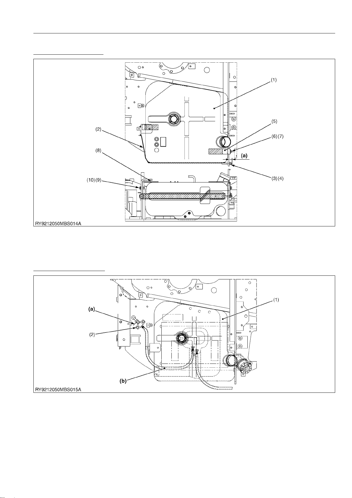
U48-4,U55-4, WSM
KiSC issued 03, 2010 A
[2] FUEL TANK
Assembling the fuel tank
MACHINE BODY
(1) Fuel tank assembly
(2) Band, assy (fuel tank)
(3) Lock nut
(4) Flat metal washer
(5) Plate, assy
(1, fuel tank support)
(6) Bolt (M10 x 20)
(7) Flat metal washer
(8) Plate, assy
(2, fuel tank support)
(9) Bolt (M10 x 25)
(10) Flat metal washer
(a) Tolerance from the frame
(swivel) partition plate to
band screw part : 20 to
25 mm, 0.79 to 0.98 in.
RY9212050MBS0001US0
Assembling the fuel hose
(1) Fuel tank assembly (2) Bolt (M10 x 25) (a) Cock closed position (b) Be careful to make sure the
hose does not get caught
between the frame (swivel)
and the fuel tank
RY9212050MBS0002US0
1-S5
Page 66

U48-4,U55-4, WSM
KiSC issued 03, 2010 A
MACHINE BODY
Fuel hose clamp, guide position
(1) Guide
(2) Clamp
(3) Clamp
RY9212032MBS0014US0
1-S6
Page 67

U48-4,U55-4, WSM
KiSC issued 03, 2010 A
Fuel hose route (U48-4, U55-4)
MACHINE BODY
(1) Drain cock
(2) Fuel tank
List of fuel hoses
(3) Water separator
(4) Fuel pump
Fuel tube Protection tube Hose band
Part Length Part Length In / Out side
(A) RD451-51332 730 mm, 28.7 in. RD451-51341 610 mm, 24 in. 09318-88130
(B) 09664-82100 2100 mm, 82.7 in, RC301-51151 2000 mm, 78.7 in. 14911-42751
(C) 09664-80340 340 mm, 13.4 in. RD451-51352 260 mm, 10.2 in. 14911-42751
(D) 09664-80260 260 mm, 10.2 in. RD451-51382 200 mm, 7.9 in. 14911-42751
(E) 09664-80260 260 mm, 10.2 in. RD451-51382 200 mm, 7.9 in. 14911-42751
(F) 09664-40500 500 mm, 19.7 in. RC461-51641 450 mm, 17.7 in. 14971-42751
(G) 09664-41750 1750 mm, 68.9 in. RD451-51392 1650 mm, 65 in. 14971-42751
(H) 09664-80040 40 mm, 1.6 in. – – 14911-42751
(I) 09664-80040 40 mm, 1.6 in. – – 14911-42751
(J) 09664-42100 2100 mm, 82.7 in, RB441-51221 2000 mm, 78.7 in, 14971-42751
(K) 09664-60420 420 mm, 16.5 in. – – –
(5) Fuel filter
(6) Engine
(7) Fuel cooler
RY9212052MBS0008US0
1-S7
Page 68

U48-4,U55-4, WSM
KiSC issued 03, 2010 A
[3] HYDRAULIC OIL TANK
(1) Hydraulic oil tank components
MACHINE BODY
(1) Hydraulic oil tank
(2) Cover (tank)
(3) O-Ring
(4) Filter (return)
(5) Stopper (return filter)
(6) Bolt (M8 x 16)
Tightening torque Bolt (25)
(7) Plug (fill)
(8) O-Ring
(9) Bolt (M10 x 16)
(10) Filter, assy (suction)
(11) Pin (suction filter)
(12) O-Ring
77.5 to 90.2 N·m
7.9 to 9.2 kgf·m
57.2 to 66.5 lbf·ft
Apply thread locking compound (Loctite 271) to the bolt (25)
(13) Bolt (M10 x 16)
(14) Plug (G1/4)
(15) O-Ring
(16) Plug
(17) Sealing washer
(18) Filter (blazer)
(19) Metal washer
(20) Sealing washer
(21) Flange holder
(22) Tube (blazer)
(23) Magnet plug
(24) Sealing washer
(25) Bolt (M12 x 30)
RY9212050MBS0030US0
1-S8
Page 69

U48-4,U55-4, WSM
CAUTION
KiSC issued 03, 2010 A
(2) Hydraulic oil return filter replacement procedure
Removing the cover (tank)
1. Loosen the hose clamp (3), remove the hose (return) (4), hose
(return, cooler) (5), from the cover (tank) (1) side.
2. Remove the cover (tank) (1) mounting bolt (2).
(1) Cover (tank)
(2) Bolt
(3) Hose clamp
3. Pull up the cover (tank) (1) and remove the filter (return) (6).
(1) Cover (tank) (6) Filter (return)
MACHINE BODY
(4) Hose (return)
(5) Hose (return, cooler)
RY9212001MBS0052US0
RY9212001MBS0053US0
4. Clamp in a vice, loosen the set bolt (7), and remove the stopper
(8).
(7) Set bolt (8) Stopper
RY9212001MBS0054US0
5. Remove the filter (return) (9) using a wrench (1).
Wrench : 41 mm, 1.6 in. (two opposite faces)
Tightening torque Filter (return) (9)
68.6 to 78.4 N·m
7.0 to 8.0 kgf·m
50.6 to 57.8 lbf·ft
• When tightening the filter (return), tighten with the wrench
(1) on the nut (b) shown in the diagram to the left.
If the wrench (1) is placed on the nut on (a) side, the filter
will break.
• Assemble the filter so that opposite sides of the hexagonal
part of the filter fully engages with the flat surfaces of the
stopper (2).
(1) Wrench
(2) Stopper
(9) Filter (return)
RY9212001MBS0055US0
1-S9
Page 70

U48-4,U55-4, WSM
CAUTION
KiSC issued 03, 2010 A
(3) Filter (suction) replacement procedure
1. Remove the filter (return) from the tank.
(Refer to the chapter Filter (Return) Assembly/Disassembly.)
Remove the bracket (1).
(1) Bracket (2) Bolt (M10 x 16)
2. Remove the bolt and the suction filter mounting pin (3).
(3) Pin (suction)
MACHINE BODY
RY9212001MBS0056US0
RY9212001MBS0057US0
3. Hold onto the upper part of the filter (support) and remove the
filter (suction) (4) from the tank.
• Remove only the strainer (1) and when replacing with a new
part, set the overall length (A) to 380 mm (15 in.).
Tightening torque Nut (2)
(1) Strainer
(2) Nut
(4) Filter (suction)
(A) 380 mm, 15 in.
16 to 24 N·m
1.6 to 2.4 kgf·m
12 to 18 lbf·ft
RY9212050MBS0026US0
1-S10
Page 71

U48-4,U55-4, WSM
KiSC issued 03, 2010 A
(4) Filter (breather) replacement procedure
1. Loosen the bolt (1), and remove the washer (2).
(1) Bolt (2) Metal washer
2. Remove the filter (breather) (3) from the tank.
(3) Filter (breather)
MACHINE BODY
RY9212001MBS0059US0
RY9212001MBS0060US0
1-S11
Page 72

U48-4,U55-4, WSM
KiSC issued 03, 2010 A
(5) Assembly of anti vibration support for the hydraulic oil tank
MACHINE BODY
(1) Plate (stay, oil tank)
(2) Anti-vibration rubber
(3) Stay (tank, anti-vibration)
(4) Base (tank, anti-vibration)
(5) Frame (arch)
Tightening order for each bolt
(a) through (d) in the diagram to the left.
1. After assembly, fully tighten the (a) bolt to the arch.
2. Lightly tighten bolts (b), (c), and (d) together with the assembly
3. Tighten in the order of (b)→(c)→(d).
4. Be sure the (b) bolt is assembled straight and not cross
Tightening torque Bolts (a) (b) (c) (d)
(a) Flange bolt (M12 x 20)
(b) Bolt (M12 x 60)
(c) Bolt (M12 x 30)
(d) Bolt (M12 x 30)
RY9212001MBS0061US0
The tightening order for each bolt is indicated using the letters
of their associated components.
threaded.
77.5 to 90.2 N·m
7.9 to 9.2 kgf·m
57.2 to 66.5 lbf·ft
Apply thread locking compound (Loctite 271) to (b)
RY9212001MBS0062US0
1-S12
Page 73

U48-4,U55-4, WSM
KiSC issued 03, 2010 A
[4] ENGINE
(1) Engine mount
[A] Engine mount structural components
MACHINE BODY
(1) Bracket (1, engine)
(2) Bolt (M12 x 35)
(3) Bracket (2, engine)
(4) Bracket (3, engine)
(5) Bracket (4, engine)
Tightening torque Bolt (9)
(6) Support (engine)
(7) Anti-vibration rubber (450)
(8) Cap
(9) Bolt (M16 x 110)
(10) Collar
196.1 to 225.6 N·m
20 to 23 kgf·m
144.7 to 166.3 lbf·ft
(11) Bolt (M16 X 70)
(12) Flat metal washer
(13) Tray (engine)
(14) Fuel tube
Apply thread locking compound (Loctite 271) onto part number (2), (9), (11) and (18).
(15) Pipe clip
(16) Flat washer assembly bolt
(17) Stay (harness clamp)
(18) Flat washer assembly bolt
RY9212050MBS0031US0
1-S13
Page 74

U48-4,U55-4, WSM
KiSC issued 03, 2010 A
(2) Muffler
[A] Muffler structural components
MACHINE BODY
(1) Flange (muffler)
(2) Gasket (muffler, NA)
(3) Bolt (M10 x 25)
(4) Gasket (muffler)
(5) Bracket (muffler)
(6) Bolt (M8 x 20)
(7) Pipe (muffler)
(8) Band (flange muffler)
(9) Band (muffler pipe)
(10) Bolt (M8 x 85)
(11) Bolt (M8 x 75)
(12) Flat metal washer
(13) Spring washer
(14) Nut
(15) Insulation (1, muffler)
(16) Insulation (2, muffler)
(17) Wire
RY9212032MBS0027US0
[B] Assembling of muffler
Assembling pipe (muffler) clamp
(1) Band (flange muffler)
(2) Flange (muffler)
(3) Bracket (muffler)
(a) Bolt
(b) Bolt
(c) Bolt
(A) X surface
(B) Y surface
(C) Z surface
Being careful not to dent or deform the tail pipe, tighten with the
following torques.
3.9 to 5.9 N·m
Tightening torque Band (flange muffler) (1)
0.4 to 0.6 kgf·m
2.9 to 4.3 lbf·ft
RY9212032MBS0028US0
1-S14
Page 75

U48-4,U55-4, WSM
CAUTION
KiSC issued 03, 2010 A
MACHINE BODY
Assembly procedure for the muffler assy
1. Lightly tighten the bolts (a), (b), (c).
• Be sure there are not any gaps on the X surface, Y surface,
or Z surface.
2. Tighten the (a) bolt.
3. Tighten the (b) bolt.
4. Tighten the (c) bolt.
(1) Tail pipe
(2) Bonnet
(3) Arch, Air cleaner
[A] Assembling of the Arch and Air Clearance
(A) Clearance 15 mm, 0.59 in. ≤
RY9212052MBS0003US0
(1) Air cleaner, assy
(2) Hose (inlet)
(3) Hose clamp (with screw)
(4) Hose (1, inlet)
(5) Pipe band
(6) Hose (3, inlet)
(7) Indicator
(8) Frame (arch)
(9) Frame (2, arch)
(10) Bolt (M14, arch)
(11) Collar (arch)
(a) Place in the frame (arch)
guide
(b) 30 °
RY9212001MBS0082US0
Assembling the Arch
There is a counter bore in the arch mounting area on the swivel
frame and it has a structure where a collar (arch) (4) is inserted and
joined with the arch.
Be careful not to lose the collar (arch) (4) when disassembling
and reassembling and tighten using the following torque.
123.6 to 147.1 N·m
Tightening torque Bolt (3)
12.6 to 15.0 kgf·m
91.17 to 108.4 lbf·ft
Apply thread lock compound (Loctite 271).
(1) Frame (arch)
(2) Frame (2, arch)
(3) Bolt (M14, arch)
(4) Collar (arch)
RY9212050MBS0027US0
1-S15
Page 76
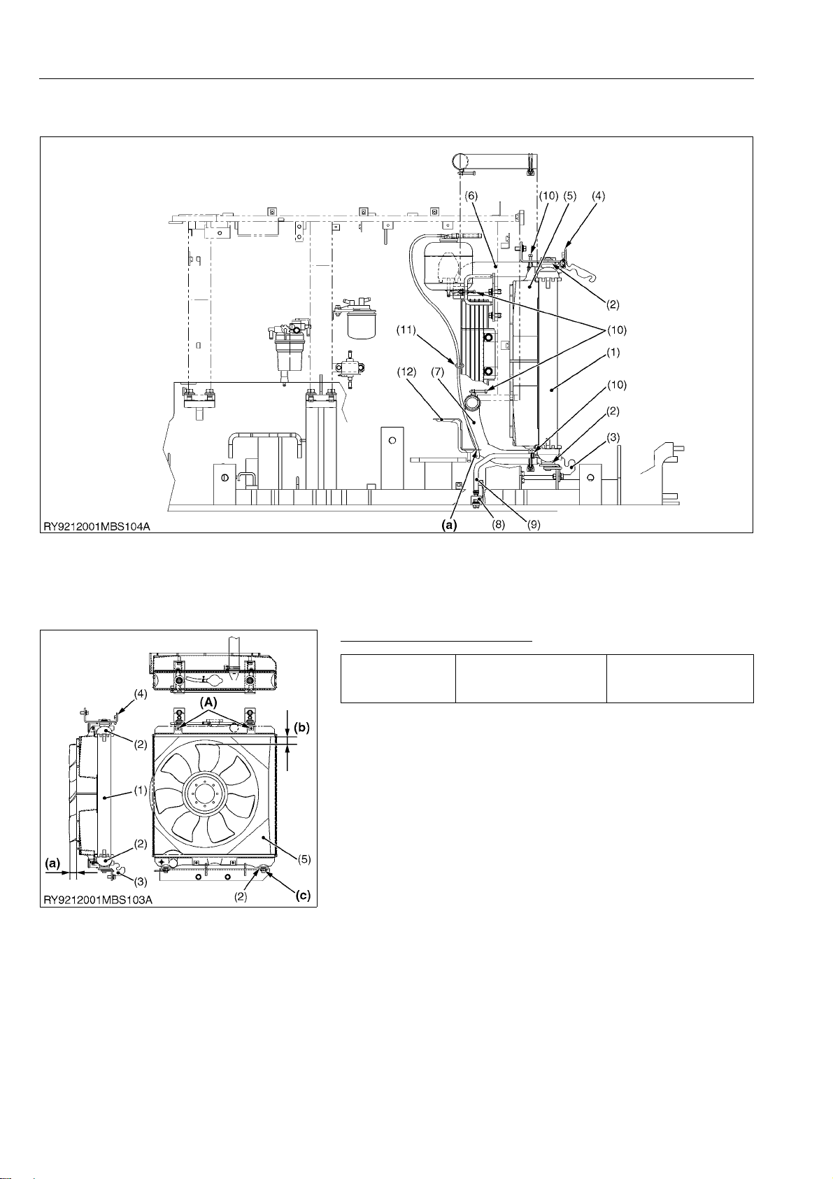
U48-4,U55-4, WSM
KiSC issued 03, 2010 A
(4) Radiator
[A] Assembling of the Radiator
MACHINE BODY
(1) Radiator, ASSY
(2) Rubber (radiator mount)
(3) Bracket (1, radiator)
(4) Bracket (2, radiator)
(5) Shroud (fan)
(6) Hose (upper, WP)
(7) Hose (lower, WP)
(8) Coupler (drain)
(9) Hose (drain)
(10) Clamp
(11) Cord band
(12) Tray (engine oil)
Assembling the Shroud (fan)
Tightening torque Bolt (A)
(1) Radiator, ASSY
(2) Rubber (radiator mount)
(3) Bracket (1, radiator)
(4) Bracket (2, radiator)
(5) Shroud (fan)
(A) Bolt (M6 x 16)
(a) Pass through hole
RY9212001MBS0084US0
4.5 to 5.5 N·m
0.46 to 0.56 kgf·m
3.4 to 4.0 lbf·ft
(a) Tolerance from shroud (fan) to
fan : 30 ± 3 mm, 1.2 ± 0.1 in.
(b) Gap between fan and shroud
(fan) at least 10 mm, 0.4 in.
(c) Be sure that the tab is fully
inserted into the hole in the
bracket.
RY9212001MBS0085US0
1-S16
Page 77

U48-4,U55-4, WSM
KiSC issued 03, 2010 A
(5) Oil cooler
[A] Assembling of the Oil Cooler
MACHINE BODY
(1) Oil cooler
(2) Bracket (oil cooler)
(3) Bolt (M8 x 20)
(4) Flat metal washer
(5) Bolt (M8 x 25)
(6) Bolt (M8 x 20)
(7) Pipe joint (oil cooler, L)
(8) Pipe joint (oil cooler, R)
Oil cooler assembly procedure
1. Lightly tighten bolts (3), (5), and (6).
2. Tighten bolt (6).
Tightening torque Bolt (6)
3. Tighten bolt (3).
Tightening torque Bolt (3)
4. Tighten bolt (5).
Tightening torque Bolt (5)
(3) Bolt (M6 x 14)
(5) Bolt (M8 x 25)
(6) Bolt (M8 x 20)
(9) Guide (hose, PP)
(10) Cooler (fuel)
RY9212032MBS0029US0
17.7 to 20.6 N·m
1.8 to 2.1 kgf·m
13.1 to 15.1 lbf·ft
9.8 to 11.3 N·m
1.0 to 1.15 kgf·m
7.3 to 8.3 lbf·ft
23.5 to 27.5 N·m
2.4 to 2.8 kgf·m
17.4 to 20.2 lbf·ft
RY9212032MBS0030US0
1-S17
Page 78

U48-4,U55-4, WSM
KiSC issued 03, 2010 A
(6) Accelerator cable
MACHINE BODY
(1) Motor ASSY (AI)
(2) Cable (accelerator)
(3) Sensor (accelerator)
(4) Bracket (sensor, AI)
(5) Washer head machine
screw
(6) Machine screw (taptite)
(7) Spring Pins
(8) Rod (AI motor)
(1) Motor ASSY (AI)
(2) Cable (accelerator)
(3) Sensor (accelerator)
(4) Bracket (sensor, AI)
(5) Washer head machine
screw
(6) Machine screw (taptite)
(9) Flat metal washer
(10) Snap pin (6, with bleed
prevention)
(11) Bracket (AI motor)
(12) Bolt (M10 x 20)
(13) Bolt (M6 x 16)
(14) Flat metal washer
(15) Cotter pin
RY9212001MBS0088US0
(a) Gap of at least 1 mm
(0.04 in.) at max engine
speed
RY9212001MBS0089US0
Motor, assy (AI) tightening torque
Tightening torque Bolt (12)
Sensor (accelerator) tightening torque
Tightening torque Bolt (5)
1-S18
2.45 to 3.92 N·m
0.25 to 0.40 kgf·m
1.81 to 2.89 lbf·ft
RY9212050MBS0028US0
1.47 to 1.96 N·m
0.15 to 0.20 kgf·m
1.09 to 1.94 lbf·ft
RY9212050MBS0029US0
Page 79

U48-4,U55-4, WSM
KiSC issued 03, 2010 A
[5] ASSEMBLING OF OPERATING LEVERS
(1) Travel lever
MACHINE BODY
(1) Lever (travel, left)
(2) Lever (travel, right)
(3) Bolt (M8 x 20)
(4) Grip (travel)
(a) 193 ± 5 mm, 7.6 ± 0.2 in.
(b) When in neutral
(c) To-and-fro difference between
left and right levers should be
within 2 mm, 0.08 in.
(d) Gap between left and right levers
: 11 to 22 mm, 0.43 to 0.87 in.
RY9212032MBS0031US0
Lever (travel, left), lever (travel, right) assembly
The pilot valve side is aluminum die cast so be careful not to
over tighten; tighten to the torques indicated below.
Tightening torque Bolt (3)
(1) Lever (travel, left)
(2) Lever (travel, right)
(3) Bolt (M8 x 20)
(4) Grip (travel)
(5) Washer head bolt
(6) Valve, assy (PV, travel)
(7) Damper (HST)
(8) Headed pin
(9) Snap pin 8
(10) Flat metal washer
(11) Pedal assy (travel left)
(12) Pedal (travel 2)
(13) Pedal assy (travel right)
(14) Headed pin
(15) Flat metal washer
(16) Snap pin
(17) Bolt (M10 x 25)
17.7 to 20.6 N·m
1.8 to 2.1 kgf·m
13.1 to 15.1 lbf·ft
RY9212032MBS0032US0
1-S19
Page 80

U48-4,U55-4, WSM
KiSC issued 03, 2010 A
(2) Blade lever
MACHINE BODY
(1) Plate (blade)
(2) Bolt (M10 x 30)
(3) Lever (blade)
(4) Bolt (M8 x 16)
(5) Bolt (M10 x 25)
(6) Grip (two gears)
Assembling the lever (blade)
Tightening torque Lever (blade) (3)
(1) Plate (blade)
(2) Bolt (M10 x 30)
(3) Lever (blade)
(4) Bolt (M8 x 16)
(5) Bolt (M10 x 25)
(a) 60 mm, 2.4 in.
(b) 65 °
RY9212001MBS0094US0
23.5 to 27.5 N·m
2.4 to 2.8 kgf·m
17.4 to 20.2 lbf·ft
(6) Grip (two gears)
(7) Button (switch, green)
(8) Pan head machine screw
(9) Plate spring (capacitor)
(10) Washer head machine screw
RY9212001MBS0095US0
Assembling the plate (blade)
Tightening torque Plate (blade) (1)
1-S20
39.2 to 45.1 N·m
4.0 to 4.6 kgf·m
29.0 to 33.2 lbf·ft
RY9212001MBS0096US0
Page 81

U48-4,U55-4, WSM
KiSC issued 03, 2010 A
3. TRACK FRAME
[1] ASSEMBLING OF SWIVEL BEARING
(1) Swivel bearing assembly procedure
1. Component names
No. in
Figure
(1) Bearing (swivel) 1 1
(2) Bolt (M16 x 60) 22 24
(3) Diaphragm spring 44 48
(4) Bolt (M16 x 55) 22 24
2. Assembly position
Mount the inner tire soft zone ('S' mark) (d) on the right side of
the body.
3. Swivel bearing tightening torque
After lightly tightening, tighten to the torque indicated below
from a diagonal angle.
Tightening torque Swivel bearing (1)
Component names
MACHINE BODY
Q'ty
U48-4 U55-4
259.9 to 304 N·m
26.5 to 31 kgf·m
191.7 to 224 lbf·ft
Apply thread lock compound. (Loctite 271)
4. Apply grease to the tooth surfaces
Apply grease so that it covers the entire bearing teeth surfaces.
(a) Ball insert groove (external tire
soft zone)
(b) Tooth surface grease application
zone
(c) Port for applying grease to the
ball (mate with hole in swivel
frame)
(d) 'S' Mark
A : Rear of vehicle
B : Front of vehicle
RY9212052MBS0004US0
(2) Swivel bearing external dimensions
No. in
Figure
A 60 mm, 2.4 in. 60 mm, 2.4 in.
B 50 mm, 2.0 in. 47 mm, 1.8 in.
C 694 mm, 27.3 in. 770 mm, 30.3 in.
D P.C.D. 662 mm, 26.1 in. P.C.D. 742 mm, 29.2 in.
E 605 mm, 23.8 in. 689 mm, 27.1 in.
F P.C.D. 552 mm, 21.7 in. P.C.D. 638 mm, 25.1 in.
G 529 mm, 20.8 in. 610 mm, 24 in.
H P.C.D. 507 mm, 20.0 in. P.C.D. 588 mm, 23.1 in.
I 495.5 mm, 19.5 in. 574 mm, 22.6 in.
U48-4 U55-4
Size
RY9212052MBS0005US0
1-S21
Page 82

U48-4,U55-4, WSM
CAUTION
KiSC issued 03, 2010 A
MACHINE BODY
(3) Measuring the swivel bearing play
1. Attach the dial gauge and the dial gauge fixture on the machine
front. (Measurement position differs with the machine model.)
2. Fully stretch the arm and place the bucket in the crowded
position. Set the dial gauge to the zero point.
3. Using the attachment, tilt up the machine body, and take the dial
gauge reading. Make this measurement several times and take
their average as the final measurement.
• Perform the measurement three times, determine the
average value, and take this as the measured value.
U48-4
U55-4
(L) Measurement position
(L) : 50 mm (2.0 in.)
away from swivel race
(L) : 20 mm (0.8 in.)
away from swivel race
Factory
spec..
Allowable
limit
Factory
spec..
Allowable
limit
2.36 mm
0.1 in.
4.72 mm
0.19 in.
1.28 mm
0.05 in.
2.56 mm
0.10 in.
RY9212052MBS0007US0
1-S22
Page 83

U48-4,U55-4, WSM
CAUTION
WARNING
KiSC issued 03, 2010 A
MACHINE BODY
[2] TRACK
(1) Assembly / disassembly of rubber track
• The pressure in the grease cylinder is high so if loosened quickly, the nipple may pop off and the highly
pressurized grease in the cylinder may fly out so do not get your face nea r the nipple nor place your body
in front of the nipple and loosen the nipple gradually.
RY9212001MBS0008US0
• The excavator is equipped with an overload warning system.
When changing from rubber crawlers to steel crawlers or vice versa it is necessary to change the
overload warning setting.
Overload warning doesn't operate normally, and it could result in death or serious injury if Pre-set code
is not correctly set.
After setting, confirm overload warning operates normally based on Boom Overload Alarm Check
Method. (Refer to "Overload Warning System" at "ELECTRICAL SYSTEM" Section)
RY9212052MBS0013US0
Removing the grease nipple
1. Remove one bolt (2) and then the cover (1).
2. Place a wrench (socket) at the base of the grease nipple and
loosen slowly.
If there is a rock etc. caught in the sprocket, remove the rock
first.
98 to 107.8 N·m
Tightening torque Grease nipple
(1) Cover
(2) Bolt (M10)
(3) Grease nipple
10 to 11 kgf·m
73 to 79.5 lbf·ft
RY9212001MBS0016US0
Loosen track
1. Jack up the body using the front end and blade, expel grease
from inside the grease cylinder, and fully loosen up the track.
When the track loosens up, attach the grease nipple.
RY9212032MBS0008US0
1-S23
Page 84

U48-4,U55-4, WSM
CAUTION
CAUTION
CAUTION
WARNING
KiSC issued 03, 2010 A
MACHINE BODY
Removing the rubber tracks
1. Lift the body slightly and move the track in the forward direction
A.
Slide the track in the sideways direction at the front idler to
remove it.
Weight of rubber track : approximately 240 kg (529 lbs)
A : Forward direction B : Slide direction
RY9212032MBS0033US0
Assembling rubber tracks
1. Jack up the mini-excavator with the front-end and the blade and
assemble the track starting at the sprocket.
• Make sure to assemble the rubber track in the correct
orientation.
2. With the mini-excavator lifted slightly, hold the rubber track with
your hand on the outside, slowly turn it in the forward direction,
and set it on the stepped area of the front idler.
• Watch carefully to prevent your hands and legs from
getting caught.
• Lower the mini-excavator, drive it backwards to make sure
the tracks are on securely.
RY9212032MBS0034US0
(2) Assembly / disassembly of iron tracks
• The pressure in the grease cylinder is high so if loosened quickly, the nipple may pop off and th e highly
pressurized grease in the cylinder may fly out so do not get your face near the nipple no r place your body
in front of the nipple and loosen the nipple gradually.
RY9212001MBS0008US0
• The excavator is equipped with an overload warning system.
When changing from rubber crawlers to steel crawlers or vice versa it is necessary to change the
overload warning setting.
Overload warning doesn't operate normally, and it could result in death or serious injury if Pre-set code
is not correctly set.
After setting, confirm overload warning operates normally based on Boom Overload Alarm Check
Method. (Refer to "Overload Warning System" at "ELECTRICAL SYSTEM" Section)
RY9212052MBS0013US0
1-S24
Page 85

U48-4,U55-4, WSM
KiSC issued 03, 2010 A
MACHINE BODY
Removing the grease nipple
1. Remove one bolt (2) and then the cover (1).
2. Place a wrench (socket) at the base of the grease nipple and
loosen slowly.
If there is a rock etc. caught in the sprocket, remove the rock
first.
(1) Cover
(2) Bolt (M10)
(3) Grease nipple
RY9212001MBS0009US0
Loosen track
1. Jack up the body using the front end and blade, expel grease
from inside the grease cylinder, and fully loosen up the track.
When the track loosens up, attach the grease nipple.
RY9212032MBS0008US0
Removing the locking pin
1. Turn the track until the master pin (1) is in front of the front idler.
2. Remove the locking pin (3) from the master pin.
(1) Master pin
(2) Master link
(3) Locking pin
RY9212001MBS0103US0
Removing the master pin
1. Place a jig on the master pin and tap it out with a hammer.
Use a jig as shown in the diagram to the left for removing the
pin.
(1) Hammer
(2) Jig
(3) Block
RY9212001MBS0104US0
1-S25
Page 86

U48-4,U55-4, WSM
DANGER
KiSC issued 03, 2010 A
MACHINE BODY
Removing the shoe
1. Slowly move the travel lever to the backup position and back up
the mini-excavator.
2. Jack up the mini excavator using the front end and blade and
pull off the shoe.
• Do not place feet under the mini excavator.
• Weight of iron track : approximately 285 kg (628 lbs)
RY9212001MBS0105US0
Mounting an iron track
1. Jack up the mini excavator using the front end and blade and
place the track so that the end of the track meshes with the
sprocket under the mini excavator.
Make sure the track is placed in the correct orientation.
(1) Master link (a) Sprocket side
(b) Front idler side
RY9212001MBS0106US0
2. Raise the track using a crane and mesh it with the sprocket
teeth.
(4) Sprocket
RY9212001MBS0107US0
3. Slowly move the travel lever to the forward travel position to
mesh the track with the shoe (6).
When the track is sufficiently pulled on to where the track link
joint is at the front idler, lower the mini-excavator, and place a
block (7) under the shoe to support the shoe.
Match up both ends of the shoe, insert the master pin from the
outside of the body, insert the locking pin and bend the tip.
(5) Idler
(6) Shoe
(7) Block
RY9212001MBS0108US0
1-S26
Page 87

U48-4,U55-4, WSM
KiSC issued 03, 2010 A
[3] FRONT IDLER
(1) Assembly / disassembly of front idler
Removing the idler
1. Remove the track.
(Refer to the chapter "Track Assembly/Disassembly".)
Jack up the mini-excavator with the front-end and the blade and
place timbers etc. under the frame.
2. Using a bar, remove the front idler from the track frame along
with the yoke.
• Front idler assy weight : approximately 46 kg (100 lbs)
(1) Block
MACHINE BODY
RY9212032MBS0035US0
(2) Front idler structural components
No. Component names Q'ty
(1) Spring Pins 1
(2) Bracket (R) 4
(3) Shaft (idler) 1
(4) Idler 1
(5) Floating Seal 2
(6) Bushing 1
(7) External circlip 2
(8) O-Ring 2
(9) Bracket (L) 1
(10) Plate (yoke) 1
(11) Bolt 1
(12) Plug (R1/8) 1
RY9212001MBS0112US0
1-S27
Page 88

U48-4,U55-4, WSM
KiSC issued 03, 2010 A
[4] SPRING ASSY
(1) Assembly / disassembly of spring assy
Removing the spring assy
1. Remove the track and the front idler.
(Refer to the "Track and Front Idler" chapters for
assembly/disassembly of the track and front idler.)
After removing the front idler assy, pull out the spring assy (1)
from the track frame.
• Spring assy weight : approximately 17 kg (37 lbs)
(1) Spring assy
Rubber track specification
MACHINE BODY
RY9212001MBS0113US0
No. Component names Q'ty
(1) Bolt (spring) 1
(2) Spring 1
(3) Retainer (spring) 1
(4) Slotted nut 1
(5) Cotter pin 1
Iron track specifications
(a) Set length for rubber track : 227.5 mm, 8.96 in.
(b) Make sure the cotter pin is set in the groove of
the slotted nut
(c) Set position for iron track specifications
RY9212001MBS0114US0
No. Component names Q'ty
(1) Bolt (spring) 1
(2) Spring 1
(3) Retainer (spring) 1
(4) Slotted nut 1
(5) Cotter pin 1
(a) Set length for iron track : 242.5 mm, 9.55 in.
(b) Make sure the cotter pin is set in the groove of
the slotted nut
(c) Set position for rubber track specification
RY9212001MBS0115US0
1-S28
Page 89

U48-4,U55-4, WSM
KiSC issued 03, 2010 A
[5] CYLINDER ASSEMBLY
(1) Assembly / disassembly of cylinder assy
Removing the cylinder assy
1. Remove the track, front idler, and spring assy.
(Refer to the spring idler chapter for assembly/disassembly of
the track, front idler, and spring assy.)
After removing the spring assy, pull out the cylinder assy (1)
from the track frame.
• Cylinder assy weight : approximately 14 kg (31 lbs)
(1) Cylinder Assembly
(2) Cylinder assembly structural components
No. Component names Q'ty
(1) Rod 1
(2) Rod seal 1
(3) Backup ring 1
(4) O-Ring 1
(5) Cylinder tube 1
(6) Nipple, assy 1
MACHINE BODY
RY9212001MBS0116US0
98 to 107.8 N·m
Tightening torque Nipple, assy (6)
10 to 11 kgf·m
73 to 79.5 lbf·ft
RY9212001MBS0117US0
Rubber track specification structural components
No. Component names
(1) Idler assy
(2) Spring assy
(3) Cylinder assembly
(a) 227.5 mm, 8.96 in.
RY9212001MBS0126US0
Iron track specification structural components
No. Component names
(1) Idler assy
(2) Spring assy
(3) Cylinder assembly
(a) 242.5 mm, 9.55 in.
RY9212001MBS0127US0
1-S29
Page 90

U48-4,U55-4, WSM
KiSC issued 03, 2010 A
MACHINE BODY
Mounting an iron track guide
Tightening torque for iron track guide mounting bolt (2)
103.0 to 117.7 N·m
Tightening torque Guide (1)
10.5 to 12.0 kgf·m
76.0 to 86.8 lbf·ft
Apply thread lock compound (Loctite 271).
(1) Guide (2) Bolt (diaphragm spring flat washer)
RY9212001MBS0128US0
1-S30
Page 91

U48-4,U55-4, WSM
CAUTION
KiSC issued 03, 2010 A
MACHINE BODY
[6] TRACK ROLLER
(1) Assembly / disassembly of track roller
• The pressure in the grease cylinder is high so if loosened quickly, the nipple may pop off and the highly
pressurized grease in the cylinder may fly out so do not get your face nea r the nipple nor place your body
in front of the nipple and loosen the nipple gradually.
RY9212001MBS0008US0
Removing the grease nipple
1. Remove one bolt (2) and then the cover (1).
2. Place a wrench (socket) at the base of the grease nipple and
loosen slowly.
If there is a rock etc. caught in the sprocket, remove the rock
first.
(1) Cover
(2) Bolt (M10)
(3) Grease nipple
RY9212001MBS0009US0
Loosen track
1. Jack up the body using the front end and blade, expel grease
from inside the grease cylinder, and fully loosen up the track.
When the track is loose, attach the grease nipple and place a
block under the track frame.
RY9212032MBS0036US0
Removing the track roller
1. Loosen the track roller mounting bolt, and remove the track
roller.
Track roller weight : 10 kg (22 lbs)
RY9212001MBS0118US0
1-S31
Page 92

U48-4,U55-4, WSM
KiSC issued 03, 2010 A
Mounting the track roller
MACHINE BODY
(1) Track roller, assy (2) Bolt (3) Flat metal washer (a) Less than 1.5 mm (0.06 in.)
(gap between working
surfaces)
Please perform the procedure in reverse for assembly.
259.9 to 304.0 N·m
Tightening torque Track roller assy
26.5 to 31.0 kgf·m
191.7 to 224.2 lbf·ft
Thread locking compound : Three Bond 1305P
Apply the thread locking compound to the female threads.
RY9212001MBS0119US0
(2) Track roller structural components
No. Component names Q'ty No. Component names Q'ty
1 Shaft assy 1 7 Track roller (body) 1
2 Shaft (track roller) 1 8 Seal (floating) 2
3 Bracket (track roller) 1 9 O-Ring 1
4 Plug (R1/8) 1 10 Bracket (track roller) 1
5 Track roller 1 11 Wire 1
6 Bushing 2
RY9212001MBS0120US0
1-S32
Page 93

U48-4,U55-4, WSM
CAUTION
KiSC issued 03, 2010 A
MACHINE BODY
[7] CARRIER ROLLER
(1) Assembly / disassembly of carrier roller
• The pressure in the grease cylinder is high so if loosened quickly, the nipple may pop off and the highly
pressurized grease in the cylinder may fly out so do not get your face nea r the nipple nor place your body
in front of the nipple and loosen the nipple gradually.
RY9212001MBS0008US0
Removing the grease nipple
1. Remove one bolt (2) and then the cover (1).
2. Place a wrench (socket) at the base of the grease nipple and
loosen slowly.
If there is a rock etc. caught in the sprocket, remove the rock
first.
(1) Cover
(2) Bolt (M10)
(3) Grease nipple
RY9212001MBS0009US0
Loosen track
1. Jack up the body using the front end and blade, expel grease
from inside the grease cylinder, and fully loosen up the track.
When the track is loose, attach the grease nipple and place a
block under the track frame.
RY9212032MBS0036US0
1-S33
Page 94

U48-4,U55-4, WSM
KiSC issued 03, 2010 A
MACHINE BODY
Removing the carrier roller
1. Insert a block (2) into the gap between the carrier roller and the
track.
2. Loosen the nut (3) and remove the carrier roller (1).
Carrier weight : approximately 4 kg (9 lbs)
(1) Carrier roller
(2) Block
(3) Nut
RY9212032MBS0037US0
Mounting the carrier roller
Please perform the procedure in reverse for assembly.
77.5 to 90.2 N·m
Tightening torque Carrier roller assy
7.9 to 9.2 kgf·m
57.2 to 66.5 lbf·ft
Apply thread locking compound : (Loctite 271)
(1) Carrier roller, assy
(2) Bolt
(2) Carrier roller structural components
No. Component names Q'ty
1Roller 1
2Shaft 1
3 Shaft seal 1
4 Ball bearing 2
5 Ring stopper 1
6 Cap seal 1
7Spacer 1
8Plug 1
(3) Spring washer
(4) Nut
RY9212001MBS0122US0
RY9212001MBS0123US0
1-S34
Page 95

2 ENGINE
KiSC issued 03, 2010 A
Page 96

GENERAL
KiSC issued 03, 2010 A
CONTENTS
1. ENGINE...................................................................................................................................... 2-G1
[1] ENGINE SPECIFICATIONS................................................................................................. 2-G1
[2] PERFORMANCE CURVE .................................................................................................... 2-G3
[3] DIMENSIONS....................................................................................................................... 2-G4
2. SPECIAL TOOLS ....................................................................................................................... 2-G5
Page 97

U48-4,U55-4, WSM
KiSC issued 03, 2010 A
1. ENGINE
[1] ENGINE SPECIFICATIONS
ENGINE
U48-4
(Air conditioner type)
U48-4 Remarks
Model V2607-DI-E3-BH-4 V2607-DI-E3-BH-6
Number of cylinder 4
Bore x Stroke
Displacement 2615 cc, 159.59 in
29.5 / 2200 kW/rpm
Max. output / rpm
40.1 / 2200 PS/rpm
39.5 / 2200 HP/rpm
87 x 110 mm
3.43 x 4.33 in.
30.0 / 2200 kW/rpm
40.8 / 2200 PS/rpm
40.2 / 2200 HP/rpm
3
ISO 9249 NET
SAEJ 9249 NET
Compression ratio 20
Max. torque/rpm
Dimensions : L x W x H
Dry weight
149.6 / 1300 ± 200 N·m
15.3 / 1300 ± 200 kgf·m
110.3 / 1300 ± 200 lbf·ft
687 x 497 x 653 mm
27.0 x 19.6 x 25.7 in.
225 kg
496.0 lbs
150.3 / 1300 ± 200 N·m
15.3 / 1300 ± 200 kgf·m
110.9 / 1300 ± 200 lbf·ft
225 kg
496.0 lbs
Valve clearance 0.15 mm, 0.01in. Cold condition
Firing sequence 1-3-4-2
Combustion chamber (Direct Injection)
Compression pressure
3.20 MPa
32.6 kgf/cm
464 psi
2
Ref. valve at 150 rpm
starter speed
Fan belt Bando RPF3355 Bando RPF3350
Fuel consumption ratio
234.0 g/kWh
172.1 g/PSh
0.385 lbs/HPh
230.1 g/kWh
169.2 g/PSh
0.378 lbs/HPh
Net value
Engine speed with idling 1050 to 1200 rpm On the machine
Engine oil pressure with rated
engine rpm
Fuel injection pressure
1st stage / 2nd stage
1st stage : 18.6 MPa (190 kgf/cm
2nd stage : 21.6 MPa (220 kgf/cm
245 to 441 kPa
2.50 to 4.50 kgf/cm
35.6 to 64.0 psi
2
2
, 2700 psi)
2
, 3130 psi)
0.68 g/kWh
Engine oil consumption ratio
0.50 g/PSh
0.00112 lbs/HPh
Alternator 12 V – 720 w DENSO Co.
Charging current 60 A
Regulation voltage 14.2 ~ 14.8 V
Battery 105D31L
Electrolyte gravity 1.26 ≤
Starter 12 V – 2.0 kW DENSO Co.
Glow plug 0.95 Ω
RY9212052END0001US0
2-G1
Page 98

U48-4,U55-4, WSM
KiSC issued 03, 2010 A
ENGINE
U55-4
(Air conditioner type)
U55-4 Remarks
Model V2607-DI-E3-BH-3 V2607-DI-E3-BH-5
Number of cylinder 4
Bore x Stroke
Displacement 2615 cc, 159.59 in
33.8 / 2200 kW/rpm
Max. output / rpm
46.0 / 2200 PS/rpm
45.4 / 2200 HP/rpm
87 x 110 mm
3.43 x 4.33 in.
34.3 / 2200 kW/rpm
46.6 / 2200 PS/rpm
46.0 / 2200 HP/rpm
3
ISO 9249 NET
SAEJ 9249 NET
Compression ratio 20
Max. torque/rpm
Dimensions : L x W x H
Dry weight
169.7 / 1300 ± 200 N·m
17.3 / 1300 ± 200 kgf·m
125.2 / 1300 ± 200 lbf·ft
687 x 497 x 653 mm
27.0 x 19.6 x 25.7 in.
225 kg
496.0 lbs
170.4 / 1300 ± 200 N·m
17.4 / 1300 ± 200 kgf·m
125.7 / 1300 ± 200 lbf·ft
225 kg
496.0 lbs
Valve clearance 0.15 mm, 0.01in. Cold condition
Firing sequence 1-3-4-2
Combustion chamber (Direct Injection)
Compression pressure
3.20 MPa
32.6 kgf/cm
464 psi
2
Ref. valve at 150 rpm
starter speed
Fan belt Bando RPF3355 Bando RPF3350
Fuel consumption ratio
232.7 g/kWh
171.2 g/PSh
0.383 lbs/HPh
229.3 g/kWh
168.7 g/PSh
0.377 lbs/HPh
Net value
Engine speed with idling 1050 to 1200 rpm On the machine
Engine oil pressure with rated
engine rpm
Fuel injection pressure
1st stage / 2nd stage
1st stage : 18.6 MPa (190 kgf/cm
2nd stage : 21.6 MPa (220 kgf/cm
245 to 441 kPa
2.50 to 4.50 kgf/cm
35.6 to 64.0 psi
2
2
, 2700 psi)
2
, 3130 psi)
0.68 g/kWh
Engine oil consumption ratio
0.50 g/PSh
0.00112 lbs/HPh
Alternator 12 V – 720 w DENSO Co.
Charging current 60 A
Regulation voltage 14.2 ~ 14.8 V
Battery 105D31L
Electrolyte gravity 1.26 ≤
Starter 12 V – 2.0 kW DENSO Co.
Glow plug 0.95 Ω
RY9212052END0003US0
2-G2
Page 99

U48-4,U55-4, WSM
KiSC issued 03, 2010 A
[2] PERFORMANCE CURVE
ENGINE
(a) Brake Horse Power (kW) (b) Engine Speed (rpm) (c) Torque (N·m) (A) U48-4
(B) U55-4
RY9212052END0002US0
2-G3
Page 100

U48-4,U55-4, WSM
KiSC issued 03, 2010 A
[3] DIMENSIONS
Dimension Dimension Dimension
A 686.59 mm (27.03 in.) E 262.47 mm (10.33 in.) I 145 mm (5.71 in.)
B 389.3 mm (15.33 in.) F 234.5 mm (9.23 in.) J 145 mm (5.71 in.)
C 160 mm (6.30 in.) G 652.5 mm (25.69 in.)
D 496.97 mm (19.57 in.) H 233.1 mm (9.18 in.)
ENGINE
Component layout
No. Part name No. Part name No. Part name
(1) Injection pump (6) Oil cooler (11) Starter
(2) Governor (7) Oil filter (12) Revolution sensor
(3) Glow plug (8) Oil switch (13) Water temperature sensor
(4) Stops (9) Drain plug (oil) (14) Belt tensioner
(5) Alternator (10) Oil filter plug (15) V-belt
RY9212050END0003US0
2-G4
 Loading...