

Page 1

WORKSHOP MANUAL
KUBOTA EXCAVATOR
KX91-3S
KX121-3S
U35S,U35-3S
·D
·D
·D
, 101-3
D
,161-3S
, U45-3S
Minor change Chapter
·D
·D
Code No.97899-61260
Page 2

Record of Revisions
Symbol Date Main Revised Points & Corrective Measures Person-in-charge
1
2
3
4
Page 3

CONTENTS
I Sales Engineering Section............................................... I-1
A. Quick feature chart ................................................................................. I-2
B. Feature discriptions ................................................................................ I-4
C. New innovations ..................................................................................... I-6
D. Specifications: Super series (KTC, KCL, KTA-version).......................... I-7
II Service Engineering Section........................................... II-1
A. General outline ...................................................................................... II-2
B. Finger control service port system....................................................... II-22
C. Hydraulic system modification ............................................................. II-57
D. Hydraulic circuit diagram ..................................................................... II-91
E. Engine upgrade ................................................................................. II-109
F. Electrical system................................................................................ II-114
EU-version
KX91-3D, KX101-3D,KX121-3D, KX161-3D
U35-3D, U45-3D
PP-version
KX91-3S, KX121-3S, KX161-3S
U35S, U35-3S, U45-3S
Note: EU-version is for KE, KUK, and KBM. PP-version is for KTC, KCL, and KTA.
This WSM minor change edition has been compiled to explain the main contents of the
minor change, such as new service port system, new auto-idle system, some hydraulic
system change, engine upgrade for KX161-3S, etc.
As for the service information which are identical to the machines before minor change,
please refer to the correspondent WSM.
Page 4

WSM Minor Change I Sales Engineering Section
I Sales Engineering Section
A. Quick feature chart..............................................................I-2
B. Feature discriptions.............................................................I-4
C. New innovations..................................................................I-6
D. Specifications: Super series (KTC, KCL, KTA-version) ......I-7
I - 1
Page 5
WSM Minor Change I Sales Engineering Section
A. Quick feature chart
a. KX91-3S, KX91-3D, KX101-3D, U35S, U35-3S, U35-3D
Basic performance improved (new)
Greater working range of this class
(1) Maximum digging and dumping heights
(2) Maximum digging depth
Safeness upgraded
(1) Full-scale 4-post ROPS/FOPS
canopy
(3) Standard equipped with ROPS/
FOPS cabin (cab type)(with
steel-framed skylight)
(4) Engine neutral start
(5) Travel lock
(6) Master key-compatible immo-
bilizer (option)
Operator’s comfort
enhanced
(1) Digital navigation system
(2) Heater with outside-air inlet
defroster
(standard on cab type)
(3) Cup holder
(standard on cab type)
(4) Optional headlights
(option on cab type)
Maintainability
(1) Hydraulic components collectively located
on the right machine side
(2) Right hood fully opened
(3) Sectional dozer hose, etc.
Better maneuverability
(1) Service port local control (wrist rest type)
(2) Travel bi-speed button (dozer lever)
(3) Independent swing pedal on the left side (hydraulic pilot)
I - 2
Page 6
WSM Minor Change I Sales Engineering Section
b. KX121-3S, KX121-3D, KX161-3S, KX161-3D, U45-3S, U45-3D
New immobilizer system introduced
Thumb bracket adopted
(North America)
Travel bi-speed switch
(Dozer lever)
Independent swing pedal
on the right side
(Europe)
Service port knob control
Digital navigation system adopted
Greater engine output (KX161-3S)
Sedimenter separately located
Larger fuel tank capacity
(KX91-3S, KX161-3S)
North America, Australia, Europe
I - 3
Page 7
WSM Minor Change I Sales Engineering Section
B. Feature discriptions
(Super series)
Boom operation
Kubota's Hydraulic Matching System allows easy,
simultaneous and smooth operations of the boom,
arm, bucket and house swing. Perfectly matched
speed, power and cylinder timing deliver extraordinary responsiveness, even with the slightest operator movements or in the toughest conditions (The
KX121-3 and KX161-3 feature the Load Sensing
Hydraulic System).
Strongest bucket breakout force in its class
Kubota's Hydraulic Matching system is unmatched for power or
ease of use. Load sensing hydraulics, which automatically regulate
and distribute optimum oil amounts to each cylinder, make it ideal
for your toughest trenching projects or your lightest dozing tasks. In
any situation, you can always rely on the KX-3 Super Series for
complete work efficiency.
Safety
With our Engine Start Lockout System, the engine cranks only
when the safety levers are raised. Our safety Lever Lockout
System helps prevent unexpected excavator and attachment
movement when entering or exiting the unit. An Auto House
Parking Brake automatically locks the house in the position it
was in when the engine was shut off. This means that a swing
lock pin is no longer required, making the excavator more compact during transport and secure when parked on an incline. And
an OSHA certified ROPS/FOPS canopy and cab protects
against rollovers or falling objects.
Wide Working Range
The KX-3 Super Series' powerful and responsive front working
group is perfect for all your digging, lifting and loading jobs.
Plus, with increases and improvements to our bucket
capacities, reach and digging depths, the Super Series exceed
many of the latest construction site requirements.
I - 4
Page 8

WSM Minor Change I Sales Engineering Section
Operator comfort
Get total comfort from a spacious operating area that features ultra
quietness, deluxe climate control and a high back suspensionengineered seat with adjustable wrist rests. Well-placed controls
and levers provide an increase in deck space and foot room. A
lowsound-level cab design reduces engine vibration to a minimum.
Our ergonomic seat and wrist supports adjust to your individual
posture. And with T.P.S.S. technology, change quickly between
ISO and SAE operating patterns without tools or leaving your seat,
and with only the flick of a switch. Combined, these advantages
reduce fatigue while helping to maintain your peak performance
(A/C available only on KX121-3 and KX161-3 models).
Easy maintenance
The KX-3 Super Series not only make
daily maintenance a breeze, but also
make more-detailed periodic maintenance hassle-free as well. Wide opening
side and rear covers, as well as centrally
located components, give you quick and
easy access for the servicing of vital
areas like the engine, the fuel/water separator, the radiator, coolant, air filter, control valve and hydraulic tank.
KUBOTA engine
The ultra powerful, incredibly dependable
Kubota diesel engines deliver unmatched
horsepower while minimizing emissions
to meet EPA standards. They produce
quick starts in temperatures as low as 4qF, low sound as well as low vibration.
They even then follow through with superior fuel-efficiency.
Extraordinary stability and lifting capacity
The KX-3 Series is equipped with innovative and superior counter balancing technology for
increased excavator stability. Long tumbler distance, a lower center of gravity and Double Outer
Flanged Lower Track Rollers combine to deliver safe and effective performance when working
over the side, with hydraulic attachments mounted or when lifting a broad range of heavy objects.
I - 5
Page 9
WSM Minor Change I Sales Engineering Section
C. New innovations
DIGITAL PANEL
Informative, interactive and functional. Kubota's all-new liquid crystal display (LCD) panel
accurately shows easy-to-understand diagnostics and digital readings. The Kubota Intelligent Control System (KICS) will even alert the operator to when routine maintenance is
due. Plus, when filling-up with fuel, the KICS informs the operator that the tank is nearly full.
The panel reduces excavator downtime and repair fees for a decrease in total operating
costs.
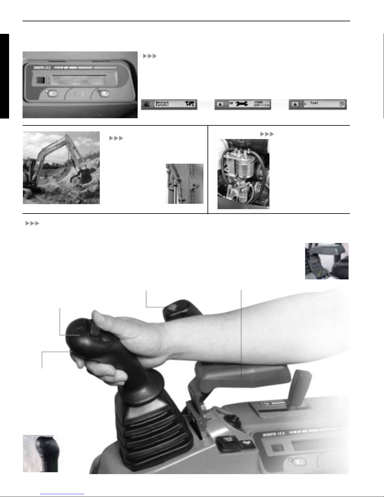
Language selection display Information when service time comes Low fuel display
USER-FRIENDLY OPERABILITY
SHORT STROKE
OPERATING LEVER
The new operating levers require less
effort and shorter movement, increasing control, responsiveness and comfort. With only the slightest flick of the
wrist, smooth excavator operation and
reduced operator fatigue are assured.
THUMB BRACKET
The optional hydraulic thumb opens up
opportunities for loading and material
handling tasks. It allows
you to pinch material
between the thumb and
bucket, retracting for
normal excavation.
Installation time is significantly reduced with
the factory installed
2 SPEED SWITCH
The new 2-Speed Travel Switch is
conveniently mounted on the dozer
lever for easier operation and control. It allows increased floor space
as well as advanced user-friendly
travel speed changes.
FUEL-WATER
SEPARATOR
The Water Separator has
been relocated to an easy to
reach position under the
improved Fuel Filter. This
gives the Super Series Models
with enhanced fuel and water
filtration, increased durability
and greater overall excavator
performance.
NEW WRIST RESTS
Set the new, custom adjustable
armrests to your favorite position, or
just move them out of the way.
Either way, they help reduce arm
movement and operator fatigue for
increased job efficiency.
BREAKER SWITCH
The breaker switch lets you manage the hydraulic breaker attachment quickly, easily and without
having to reach for the control.
Repositioned from the floor, simple forefinger activation as well as
convenient thumb operation of the
hydraulic breaker is possible.
I - 6
Page 10

WSM Minor Change I Sales Engineering Section
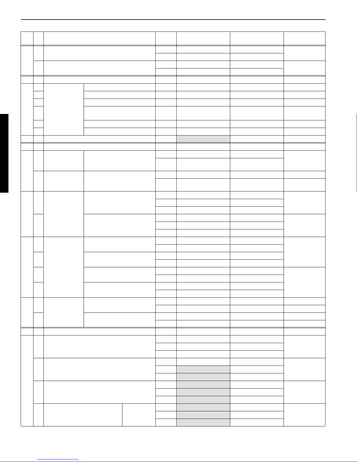
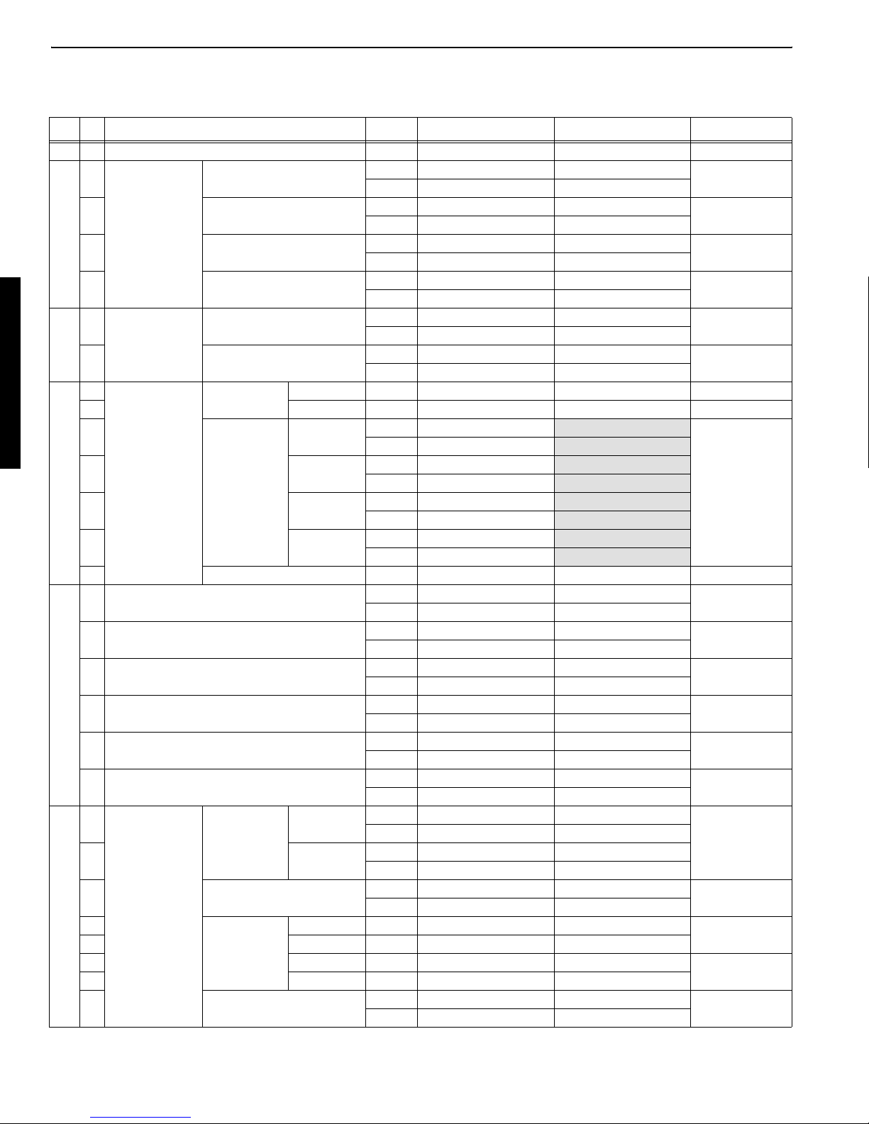
D. Specifications: Super series (KTC, KCL, KTA-version)
1.Main machine specifications
Model KX91-3S U35S / U35-3S KX121-3S KX161-3S
Type of ROPS/FOPS Canopy / Cab Canopy / Cab Canopy / Cab Canopy / Cab
Type of tracks Steel / Rubber Steel / Rubber Steel / Rubber Steel / Rubber
Engine Model Kubota D1503-M Kubota D1503-M Kubota V2203-M Kubota V2403-M
Output (SAE 1349 gross) HP(kW)/rpm 28.0 (20.9) / 2300 28.0 (20.9) / 2300 42.0 (30.7) / 2250 47.0 (34.6) / 2200
Displacement cu.in. (cc) 91.5" (1499) 91.5" (1499) 134.1" (2197) 148.5" (2434)
Dimensions Overall length ft.in. (mm) 15'7" (4760) 15'5" (4695) 16'9" (5090) 18'8" (5540)
Overall height
Overall width ft.in. (mm) 5'1" (1550) 5'7" (1700) 5'7" (1700) 6'5" (1960)
Min. ground clearance in. (mm) 11.6" (295) 11.4" (290) 13.0" (330) 12.6" (320)
Hydraulic system Pump capacity GPM (l/min) 10.9 (41.4) variable u 2
Auxiliary hydraulic flow GPM (l/min) 10.9 (41.4) 10.3 (39.1) 15.9 (60.0) 19.3 (73)
Max. breakout
force
Drive system
Swing system Unit swing speed rpm 9.4 8.9 9.4 9.3
Travel Speed
Max. traction force lbs.(kgf) 5600 (2540) 6098 (2766) 9697 (4398) 12861 (5833)
Tumbler distance ft.in. (mm) 5'1" (1560) 5'6" (1665) 5'8" (1710) 6'6" (1990)
Crawler length ft.in. (mm) 6'7" (2000) 6'11" (2100) 7'2" (2175) 8'2" (2500)
Shoe width in. (mm) 11.8" (300) 11.8" (300) 13.8" (350) 15.7" (400)
Ground contact
pressure
Boom swing
angle
canopy ft.in. (mm) 8'0" (2440) 8'0" (2440) 8'3" (2495) 8'4" (2540)
cab ft.in. (mm) 8'0" (2440) 8'0" (2440) 8'2" (2480) 8'4" (2540)
5.5 (20.9) Gear u 1
Bucket lbs.(kgf) 8059 (3655) 8397 (3809) 8754 (3970) 11118 (5043)
Arm lbs.(kgf) 3592 (1629) 4222 (1915) 3947 (1790) 4967 (2253)
Low mph (km/h) 1.9 (3.1) 1.9 (3.0) 1.7 (2.7) 1.6 (2.5)
High mph (km/h) 2.9 (4.8) 2.9 (4.6) 3.1 (5.0) 2.9 (4.6)
Canopy Cab Rubber/
Steel
Rubber/Steel psi (kgf/cm2) 4.70 (0.33) / 4.56 (0.32) 4.8 (0.34) / 5.0 (0.35) 4.41 (0.31) / 4.41 (0.31) 3.27 (0.23) / 3.41 (0.24)
Left degree 80 70 80 80
Right degree 50 50 50 50
psi (kgf/cm2) 4.64 (0.33) / 4.70 (0.33) 4.7 (0.33) / 4.8 (0.34) 4.41 (0.31) / 4.55 (0.32) 4.27 (0.30) / 4.41 (0.31)
10.3 (39.1) u 2
5.5 (20.7) u 1
25.0 (94.5) 31.4 (118.8)
Blade
Dimensions
Max.lift above ground in. (mm) 14.6" (370) 14.6" (370) 15.7" (400) 17.9" (455)
Max.drop below ground in. (mm) 14.6" (370) 14.6" (370) 15.9" (405) 14.8" (375)
Hydraulic oil (reservoir/system) gal (l) 9.5 (36) / 14.5 (55) 9.5 (36) / 14.5 (55) 11.6 (44) / 17.7 (67) 11.6 (44) / 17.7 (67)
Fuel reservoir gal (l) 13.2 (50) 10.6 (40) 16.9 (64) 18.5 (70)
Operating weight Including Canopy Rubber/Steel lbs.(kgf) 7110 (3225) / 7319 (3320) 8025 (3640) / 8234 (3735) 9063 (4110) / 9283 (4210) 11532 (5230) / 12348 (5600)
operator's weight 175lbs. Cab Rubber/Steel lbs.(kgf) 7330 (3325) / 7540 (3420) 8267 (3750) / 8477 (3845) 9261 (4200) / 9371 (4250) 11698 (5305) / 12513 (5675)
Width ft.in. (mm) 5'1" (1550) 5'7" (1700) 5'7" (1700) 6'5" (1960)
Height in. (mm) 13.2" (335) 13.2" (335) 13.8" (350) 15.4" (390)
I - 7
Page 11
WSM Minor Change I Sales Engineering Section
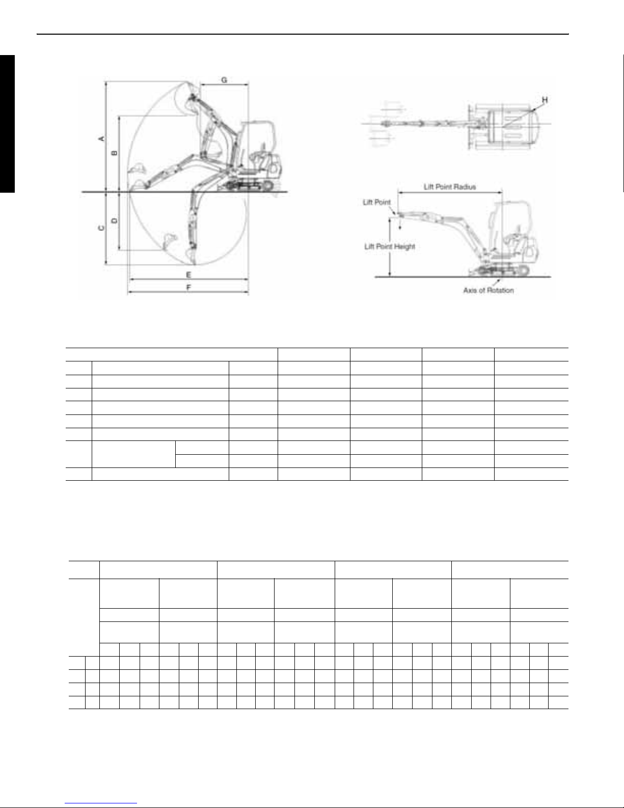
2.DIMENSIONS
3.WORKING RANGE
Model KX91-3S U35S KX121-3S KX161-3S
A Max. digging height ft.in. (mm) 16'3" (4940) 16'3" (4945) 17'10" (5420) 18'9" (5715)
B Max. dumping height ft.in. (mm) 11'7" (3530) 11'7" (3525) 12'9" (3890) 13'8" (4155)
C Max. digging depth ft.in. (mm) 10'5" (3185) 10'4" (3140) 11'6" (3505) 12'7" (3830)
D Max. vertical digging depth ft.in. (mm) 7'10" (2390) 7'4" (2230) 8'2" (2480) 8'6" (2585)
E Max. digging radius @ ground ft.in. (mm) 16'10" (5135) 16'11" (5145) 18'0" (5475) 20'1" (6130)
F Max. digging radius ft.in. (mm) 17'3" (5245) 17'3" (5260) 18'5" (5600) 20'6" (6260)
G Min. turning radius
H Min. tail turning radius ft.in. (mm) 4'4" (1310) 33.5" (850) 4'3" (1300) 3'7" (1090)
W/O ft.in. (mm) 6'2" (1870) 6'7" (2015) 6'9" (2060) 7'11" (2420)
W swing ft.in. (mm) 4'9" (1440) 5'3" (1603) 5'6" (1665) 6'5" (1955)
The company reserves the right to change the above specifications without notice. This brochure is for descriptive purpose only.
Please contact your local Kubota dealer for warranty infomation. For your safety, KUBOTA strongly recommends the use of a Rollover Protective structure (ROPS) and seat belt almost all applications.
4.LIFTING CAPACITY
U35S KX91-3S KX121-3S KX161-3S
LIFTING CAPACITY
OVER-FRONT
LIFT
POINT
HEIGHT
GL 6 2.13 1.61 - 2.13 1.42 - 1.78 1.42 1.36 1.78 1.30 1.03 3.09 2.19 2.01 3.09 1.83 1.46 4.29 2.6 2.12 4.29 2.59 1.66
BLADE DOWN
unit=1000lba unit=1000lba unit=1000lba unit=1000lba unit=1000lba unit=1000lba unit=1000lba unit=1000lba
LIFT POINT RADIUS
(ft)
4 2.79 1.76 1.58 2.52 1.39 1.10 2.42 1.58 1.43 2.29 1.27 1.01 4.03 2.44 2.15 3.15 1.78 1.43 - 3 2.25 - 2.49 1.63
2 3.28 1.91 1.63 2.42 1.35 1.08 2.95 1.74 1.50 2.18 1.23 0.99 4.66 2.67 2.27 3.02 1.73 1.41 3.9 3.33 2.36 3.9 2.4 1.59
0 3.46 1.99 - 2.37 1.33 - 3.22 1.84 1.53 2.11 1.20 0.97 4.89 2.81 2.34 2.96 1.70 1.38 4.73 3.33 2.43 4.3 2.34 1.57
(ft)
8 12 MAX 8 12 MAX 8 12 MAX 8 12 MAX 8 12 MAX 8 12 MAX 8 12 MAX 8 12 MAX
LIFTING CAPACITY
OVER-SIDE
LIFT POINT
RADIUS (ft)
LIFTING CAPAC-
ITY OVER-FRONT
BLADE DOWN
LIFT POINT
RADIUS (ft)
LIFTING CAPACITY
OVER-SIDE
LIFT POINT RADIUS
(ft)
LIFTING CAPACITY
OVER-FRONT
BLADE DOWN
LIFT POINT
RADIUS (ft)
LIFTING CAPACITY
OVER-SIDE
LIFT POINT RADIUS
(ft)
LIFTING CAPACITY
OVER-FRONT
BLADE DOWN
LIFT POINT
RADIUS (ft)
LIFTING CAPACITY
OVER-SIDE
LIFT POINT
RADIUS (ft)
Machine with ROPS canopy and rubber crawler, without bucket
I - 8
Page 12

WSM Minor Change II Service Engineering Section
II Service Engineering Section
A. General outline...................................................................II-2
a. New engineering points........................................................................ II-2
b. Photos of main modified parts.............................................................. II-3
c. Major specifications incorporated......................................................... II-4
d. Quantity water and oil........................................................................... II-5
e. Quality specifications............................................................................ II-6
B. Finger control service port system ...................................II-22
a. Feature and purpose.......................................................................... II-22
b. Outline of control system.................................................................... II-23
c. Hydraulic circuit diagram .................................................................... II-25
d. Knob structure and function ............................................................... II-26
e. Initial settings of the knob................................................................... II-32
f. S/P valve start point setting................................................................ II-34
g. Manual feeling setting ........................................................................ II-40
h. Panel display operation flow chart...................................................... II-42
i. Proportional control solenoid valve (S/P valve).................................. II-51
j. Other controls..................................................................................... II-55
k. Troubleshooting.................................................................................. II-56
C. Hydraulic system modification .........................................II-57
a. Outline................................................................................................ II-57
b. Hydraulic pump: KX161-3s, KX161-3D ............................................. II-58
c. Control valve ...................................................................................... II-63
d. Accumulator ....................................................................................... II-68
e. Hydraulic system line ......................................................................... II-73
f. Service port (S/P) solenoid valve ....................................................... II-82
g. Travel motor: KX91-3S: PP-version ................................................... II-85
h. Travel motor minor change: KX121-3SD, 161-3SD, U45-3SD......... II-89
D. Hydraulic circuit diagram..................................................II-91
E. Engine upgrade..............................................................II-109
a. General............................................................................................. II-109
b. Engine specifications........................................................................ II-109
c. Engine performance curve ............................................................... II-111
F. Electrical system............................................................II-114
II - 1
Page 13

WSM Minor Change II Service Engineering Section
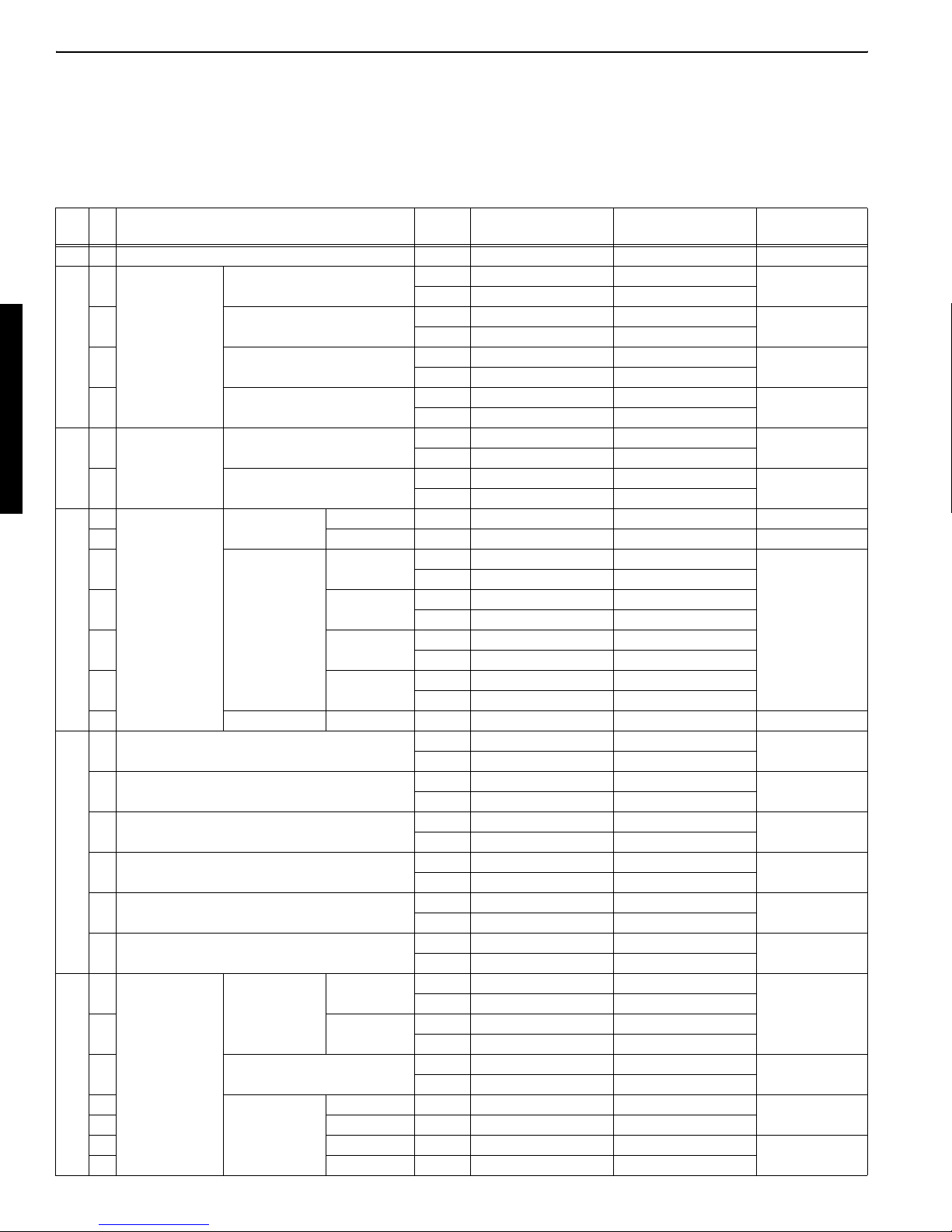
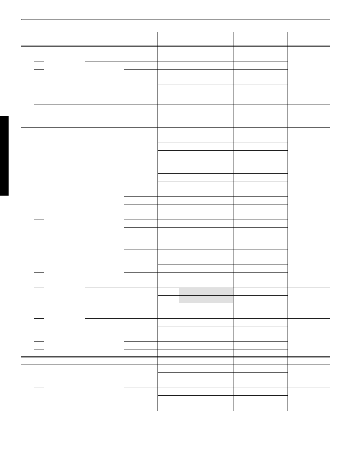
A. General outline
a. New engineering points
PP-version (KTC, KCL, KTA) EU-version
No New contents
8 Digital panel
4 Arm with thumb
bracket, option
Finger control ser-
vice port
3 Breaker switch
7 Two speed switch
6 Fuel-water separa-
tor
9 Anti-theft system - 5 Accumulator in pilot
control line
2 Proportional control
solenoid valve
10 Upgraded engine
V2403-M -
KX91-3S,
U35S, U35-3S
٤ ٤ ٤٤٤٤
٤ ٤ ٤٤٤٤
٤ ٤ ٤٤٤٤
٤ ٤ ٤٤٤٤
٤ ٤ ٤٤٤٤
٤ ٤ ٤٤٤٤
٤ ٤ ٤٤٤٤
٤ ٤ ٤٤٤٤
KX121-3S,
KX161-3S,
U45-3S
KX161-3S PP-
version only
٤
KX91-3D,
KX101-3D
٤٤٤٤
----
U35-3D KX121-3D,
KX161-3D
U45-3D
II - 2
Page 14
WSM Minor Change II Service Engineering Section
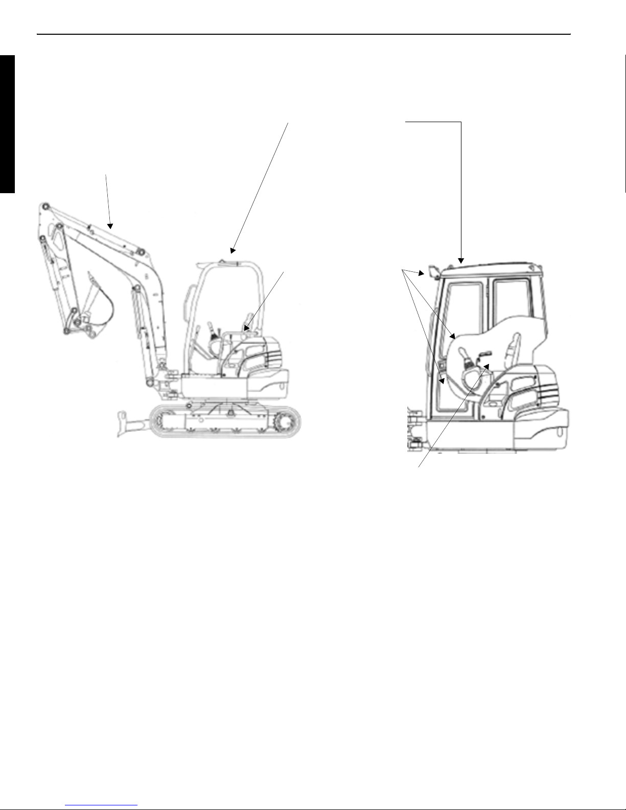
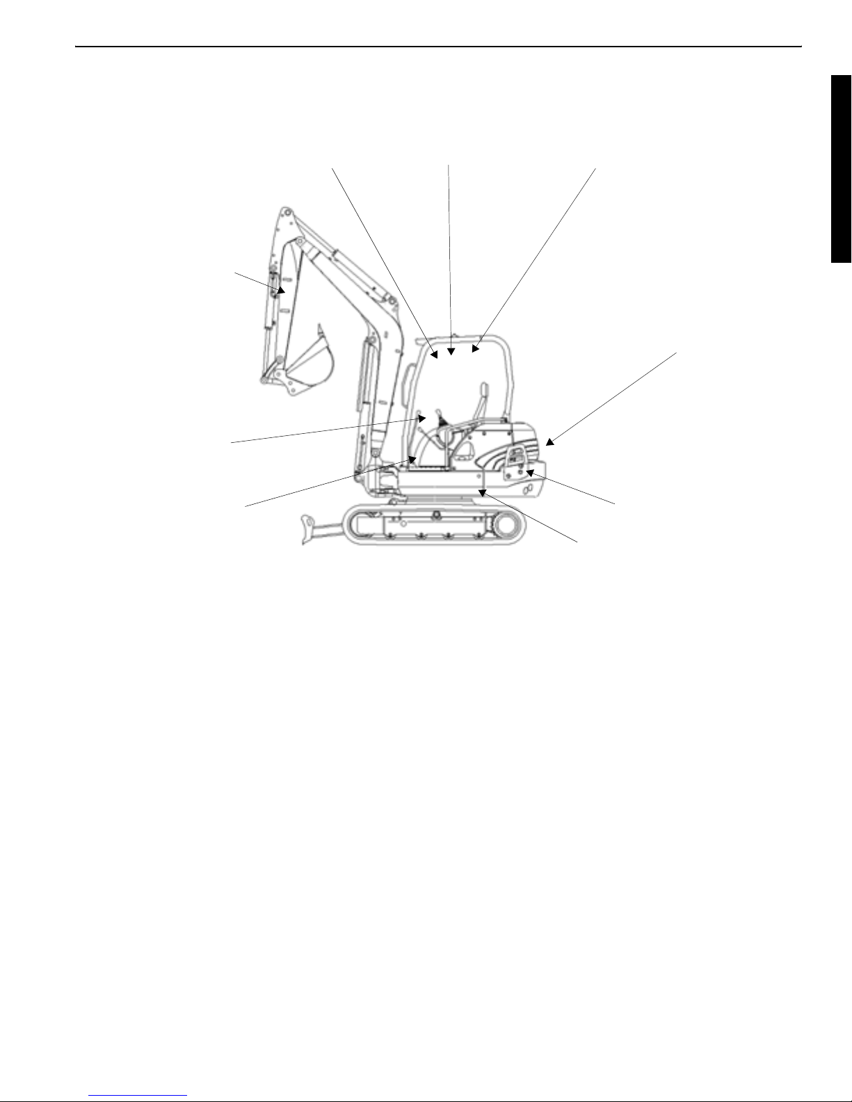
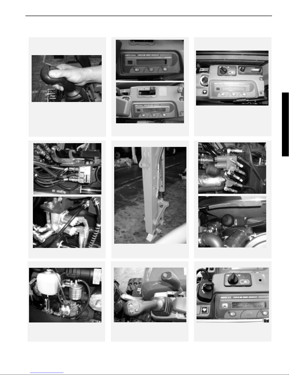
b. Photos of main modified parts
No.1 Knob switch
No.2 S/P solenoid valve
No.8 Digital meter panel
No.4 Arm with thumb bracket
No.8 Digital meter panel, AI-version
No.5 Accumulator in pilot line
No.6 Fuel-water separator
No.7 Two speed switch
II - 3
No.9 Anti-theft system
(EU-version)
Page 15

WSM Minor Change II Service Engineering Section
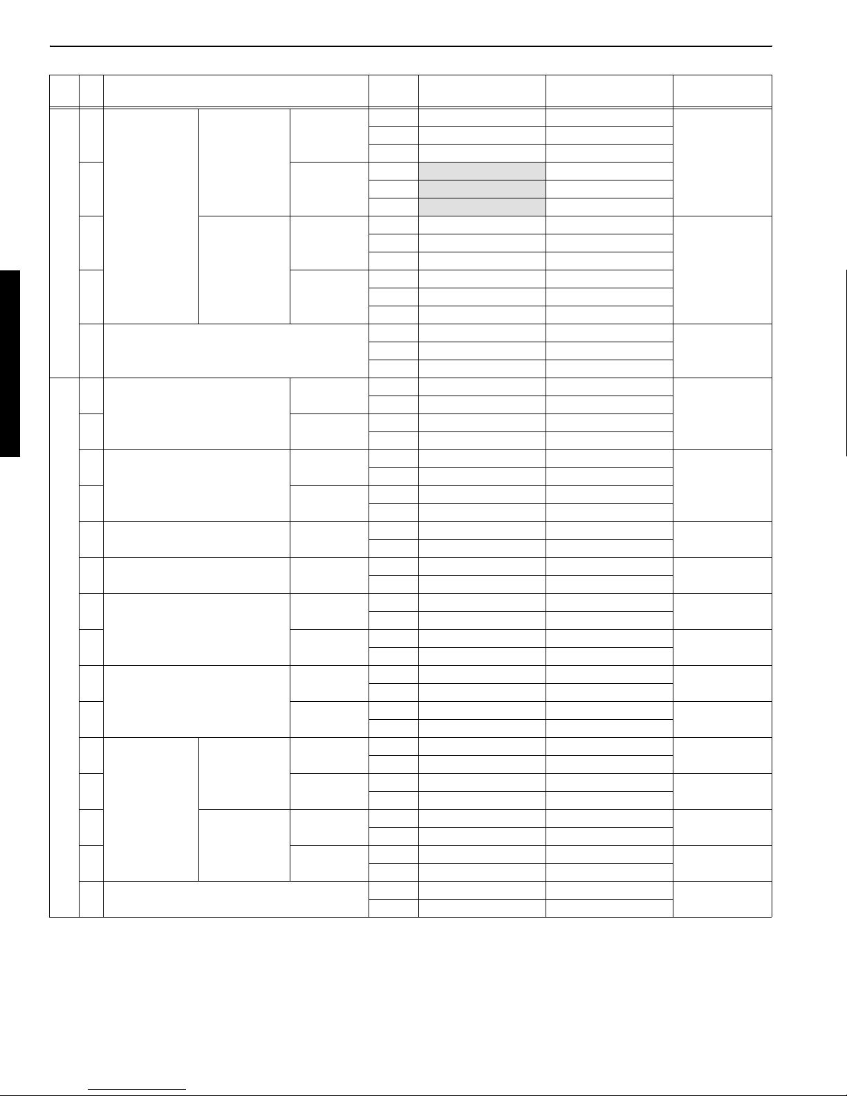
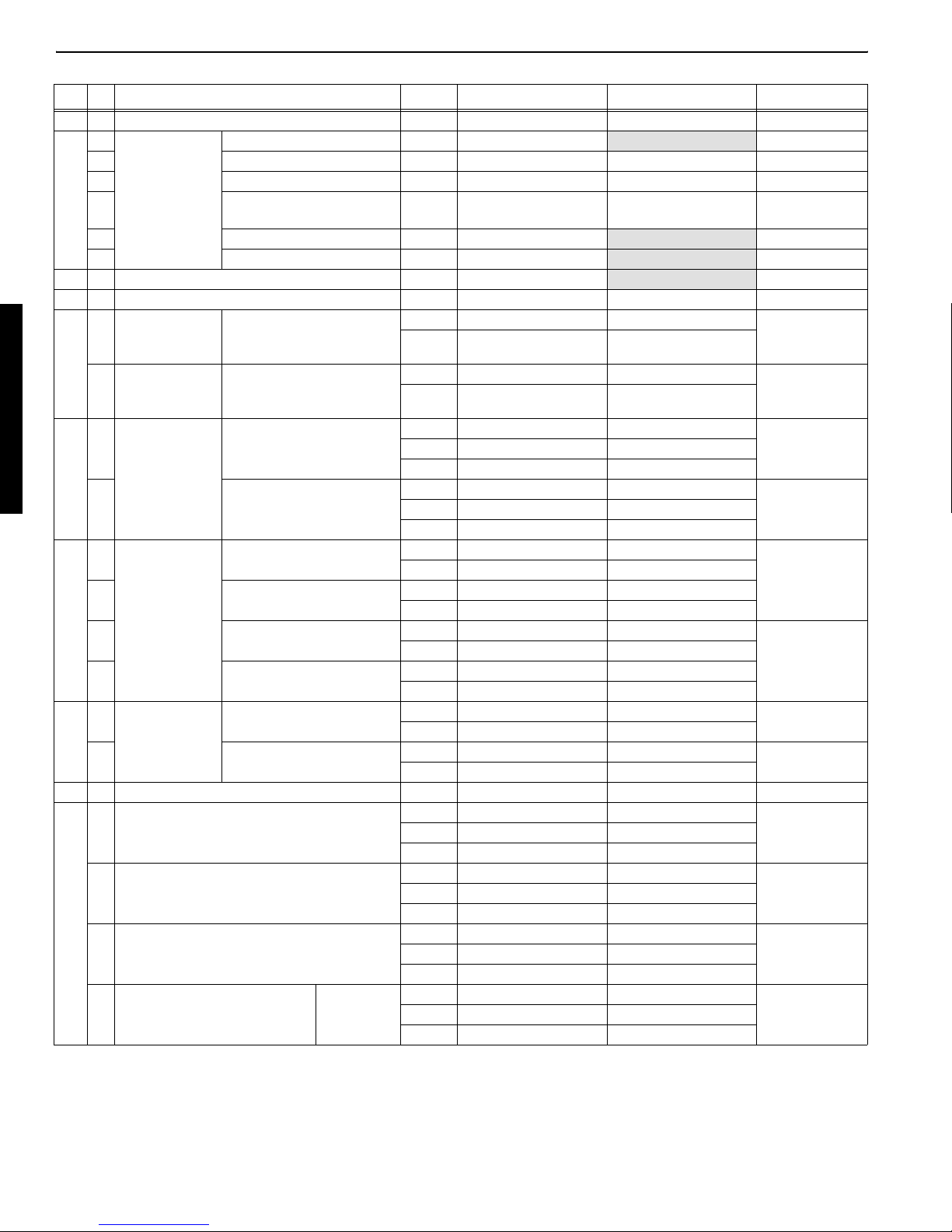
c. Major specifications incorporated
- KX91-3S, KX91-3D, KX101-3D, U35S, U35-3S, U35-3D -
Specs.
STD arm 1550mm 1275mm 1350mm 1350mm 1350mm 1350mm
Rubber track 300mm mm300mm mm
Iron track 300mm mm300mm mm
Cab (Rops / Fops)
Canopy (Rops / Fops)
Telescopic arm
(1246 - 2046)
Bucket Local content mm Local content m
Travel alarm
Canopy light
Arm rest Wrist rest
TPSS
Engines type D1503-M mmmmmm
Third line valve
KTC, KCL KTA EU EU KTC, KCL KTA EU
KX91-3S
{
{
{ ² {{²²²
² { ²²²{ ²
² { ²²²{ ²
{
{ ²² { ²
²²{{²²{
D KX101-3D
KX91-3
mm
mm
Wrist rest mm
U35S U35-3S
U35-3
{{
{{
{
D
m
m
Wrist rest
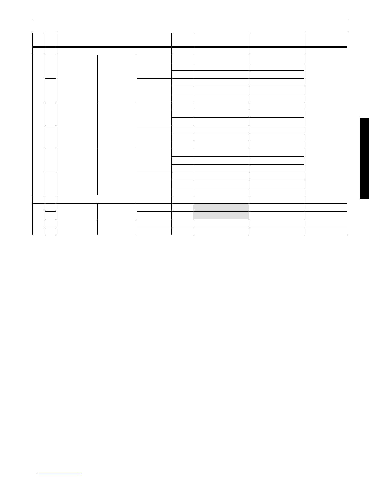
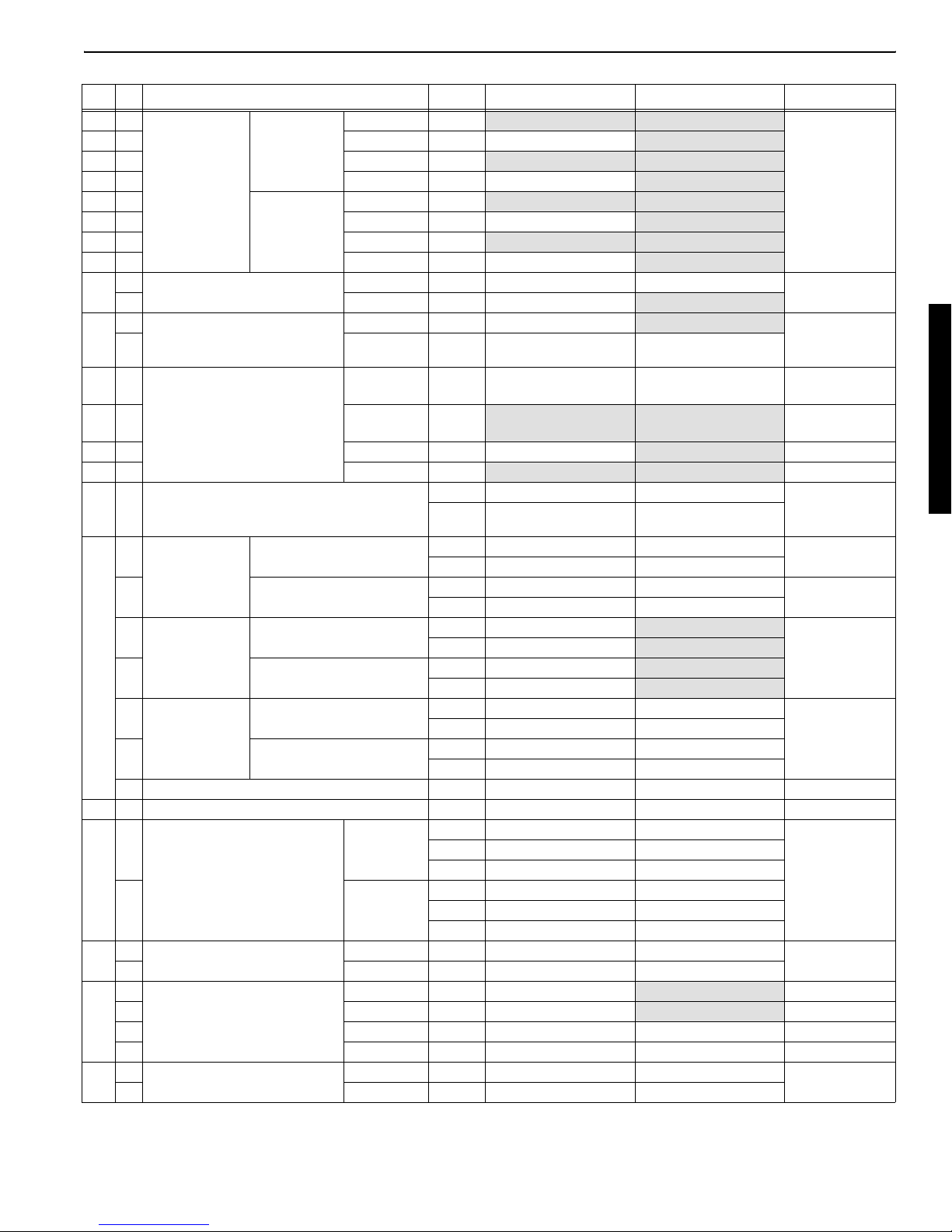
- KX121-3S, KX121-3D, KX161-3S, KX161-3D, U45-3S, U45-3D -
Specs.
STD arm 1600mm m 1300mm 1780mm m 1480mm 1360mm m
Rubber track 350mm mm400mm mm400mm m
Iron track 350mm mm
Cab (Rops / Fops)
Canopy (Rops / Fops)
Telescopic arm
(1246 - 2046)
Bucket Local content m Local content mmm
Travel alarm
Canopy light
Arm rest
TPSS
Engine
type
Third line valve
STD V2203-M-E2BH-2-N V2403-M-E2BH-1 V2203-M-E2BH-2-N
Air con. V2203-M-E2BH-3-N V2403-M-E2BH-2 V2203-M-E2BH-3-N
KX121-3S
KTC, KCL KTA EU KTC, KCL KTA EU KTA EU
{
{
²²² ²² ² ² ²
² { ²²{ ² { ²
² { ²²{ ² { ²
Wrist rest
{
{ ² { ² { ²
{{
KX121-3
Wrist rest m
D
m
m
KX161-3S
400mm /
550mm
mm
{{
{{
{
KX161-3D
mmm
mmm
Wrist rest
U45-3S
400mm /
550mm
{
U45-3D
m
Wrist rest
II - 4
Page 16

WSM Minor Change II Service Engineering Section
d. Quantity water and oil
Radiator
Reserve tank
Engine Crank case
Hydraulic oil Full
Hydraulic oil Tank
Wheel motor
Track roller
Upper roller
Front idler
Fuel tank
Unit
L
gal
L
gal
L
gal
L
gal
L
gal
L
gal
cc
gal
cc
gal
cc
gal
L
gal
KX91-3S
KX91-3
7.3
1.93
1.6
0.42
5.3
1.40
55.0
14.53
36.0
9.51
0.5
0.13
70
0.018
60
0.016
80
0.02
46.5
12.30
D
KX101-3D
U35S, U35-3S
U35-3D
Remarks
mm
L.L.C
mm
mm
mm
mm
mm
mm
mm
mm
m
40.6
10.6
SAE10W30(CD)
ISO 46
ISO 46
SAE90 (API GL-4)
SAE30(CD)
SAE30(CD)
SAE30(CD)
Radiator
Reserve tank
Engine Crank case
Hydraulic oil Full
Hydraulic oil Tank
Wheel motor
Track roller
Upper roller
Front idler
Fuel tank
Unit
L
gal
L
gal
L
gal
L
gal
L
gal
L
gal
cc
gal
cc
gal
cc
gal
L
gal
KX121-3S
KX121-3
7.4 (7.7)
1.96 (2.04)
1.1
0.29
8.5
2.25
75
19.8
46
12.2
0.5
0.13
80
0.021
60
0.016
80
0.021
64
16.9
U45-3S
D
U45-3
D
KX161-3S
KX161-3
D
Remarks
mm
m
0.5
0.13
mm
mm
mm
m
0.9
0.24
mm
mm
m
50
0.013
L.L.C
SAE10W30(CD)
ISO 46
ISO 46
SAE90 (API GL-4)
SAE30(CD)
SAE30(CD)
SAE30(CD)
mm
NOTE: In the super series, coolant amount has been increased due to the warming line of the service
port value.
II - 5
Page 17
WSM Minor Change II Service Engineering Section
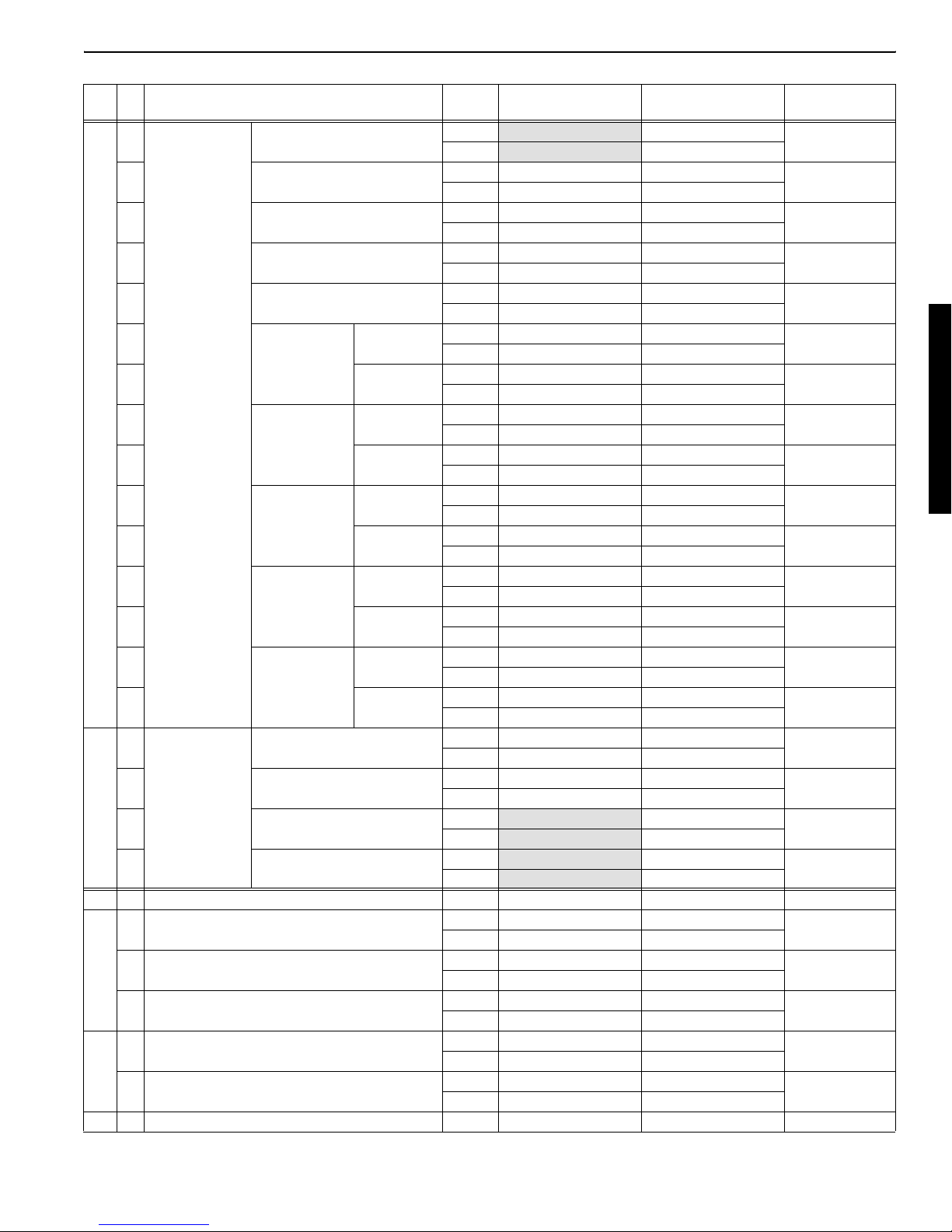
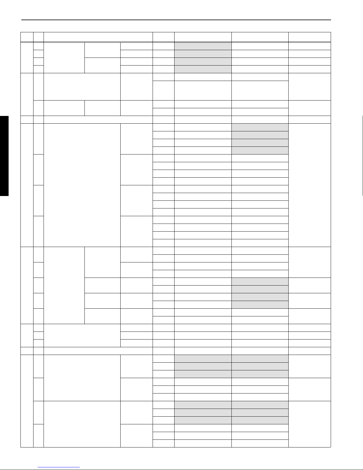
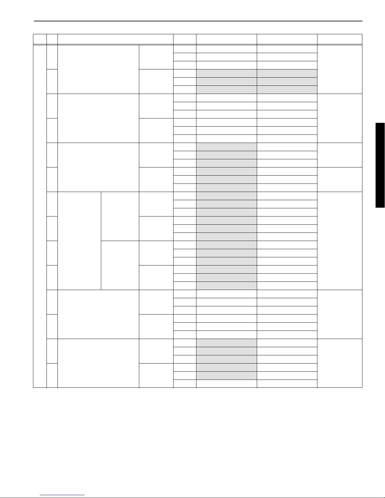
e. Quality specifications
Note: 1. Only those data with bold letter and with shadow are different from those of the previous models before modification.
2. EU-version will be announced later.
U35S ( KTC, KCL ), U35-3S ( KTA ), KX91-3S(KTC,KCL,KTA)
Machine specification : Service port, Wrist rest, STD-arm, KBT-cab, KBT-bucket.
No Specificatios Items Unit
Q1 Main Speed JIS A8404
1 1 Machine size
2
3
4
2 1 Weight
2
3 1 Performance
2Rrpm9r 0.9 9.4 r 0.9
3
4
5
6
7 Gradeability deg 30 30
4 1 Rear end min. turning radius mm 850 r 17 1310 r 26
2 Swivel frame rear ground clearance mm 525 r 11 530 r 11
3 Tambler center distance mm 1670 r 50 1560 r 47
4 Crawler total length mm 2100 r 63 2000 r 60
5 Crawler total width mm 1700 r 34 1550 r 31
6 Min. ground clearance mm 285 r 9290r 9
5 1 Front attach-
ment
2 SAE, JIS m3 0.1 0.1
3 Bucket width mm 555 r 12 555 r 11 Without side cut-
4 Swing angle Canopy L deg 70 r 280r 2
5 Canopy R deg 50 r 248r 2
6 Cabin L deg r 80 r 2
7 Cabin R deg r 48 r 2
Total length (Transport)
Total w i dth
Total height (Canopy)
Total height (Cabin)
Machine weight (Canopy)
Machine weight (Cabin)
Swivel speed
Travel speed
Bucket heaped
capacity
Lrpm9r 0.9 9.4 r 0.9
Lubber F1
Lubber F2
Iron F1
Iron F2
CECE m3 0.077
mm 4695 r 94 4760 r 95
inch 184.8 r 3.7 187.4 r 3.7
mm 1700 r 17 1550 r 16
inch 66.9 r 0.7 61.0 r 0.6
mm 2440 r 24
inch 96.1 r 0.9
mm 2440 r 24
inch 96.1 r 0.9
kg 3560 r 71 3225 r 65 Fuel tank
lbs 7848.4 r 156.5 7109.8 r 143.3
kg 3660 r 73 3225 r 67
lbs 8068.8 r 160.9 7109.8 r 147.7
km/h 3.0 r 0.3 3.1 r 0.3
mph 1.86 r 0.19 1.93 r 0.19
km/h 4.6 r 0.5 4.8
mph 2.86 r 0.31 2.98 r 0.31
km/h 2.9 r 0.3 3.0 r 0.3
mph 1.80 r 0.19 1.86 r 0.19
km/h 4.6 r 0.5 4.8 r 0.5
mph 2.86 r 0.31 2.98 r 0.31
inch 33.5 r 0.7 51.6 r 1.0
inch 20.7 r 0.4 20.9 r 0.4
inch 65.7 r 2.0 61.4 r 1.9
inch 82.7 r 2.5 78.7 r 2.4
inch 66.9 r 1.3 61.0 r 1.2
inch 11.2 r 0.4 11.4 r 0.4
yd3
yd3 0.13 0.13
inch 21.9 r 0.5 21.9 r 0.4
U35S (KTC, KCL)
U35-3S (KTA)
KX91-3S
(KTC, KCL, KTA)
r 0.5
0.01
ter
Remarks
II - 6
Page 18
WSM Minor Change II Service Engineering Section
No Specificatios Items Unit
5 8 Front attach-
ment
9 Ground level Max. digging
10 Ground level Min. finish
11 Max. digging depth mm 3115 r 62 3185 r 64
12 Max. vertical digging depth mm 2185 r 44 2390 r 48
13 Max. digging
14 Cabin mm 4660 r 93
15 Max. dump
16 Cabin mm 3265 r 65
17 Max. dump
18 Cabin mm 1125 r 34
19 Mini. turning
20 Cabin mm 2190 r 66
21 Mini. turning
22 Cabin mm -
6 1 Dozer Width mm 1700 r 5 1550 r 5
2 Height mm 335 r 25 355 r 10
3 Max. lift above GL mm
4 Max. below GL mm
Q2 Main Specs JIS A8404
1 1 Bucket tooth slaggish mm 70 >
2 Tilt amount of front attachment mm 10 >
3 Dozer's declination mm 10 >
2 1 Eccentric amount from swing center mm From swivel cen-
2 Distance to swing center mm 72 r 25.0 135 r 25.0
3 1 Approach angle deg 31.4 r 3.5 30 r 3
Max. digging radius mm 5255 r 79 5245 r 79
inch
radius
radius
Conopy mm 4890 r 98 4875 r 98
height
Conopy mm 3470 r 69
height
Conopy mm 1230 r 37 965 r 29
height (Arm
vertical)
Conopy mm 2065 r 62 1940 r 116
radius
Conopy mm radius (Left
swing)
mm 5140 r 77 5135 r 77
inch 202.4 r 3.0 202.2 r 3.0
mm 1755 r 35 1410 r 28 Bucket bottom
inch 69.1 r 1.4 55.5 r 1.1
inch 122.6 r 2.4 125.4 r 2.5
inch 86.0 r 1.7 94.1 r 1.9
inch 192.5 r 3.9 191.9 r 3.9
inch 183.5 r 3.7
inch 136.6 r 2.7
inch 128.5 r 2.6
inch 48.4 r 1.5 38.0 r 1.1
inch 44.3 r 1.3
inch 81.3 r 2.4 76.4 r 4.6
inch 86.2 r 2.6
inch -
inch -
inch 66.9 r 0.2 61.0 r 0.2
inch 13.2 r 1.0 14.0 r 0.4
inch
inch
inch 2.76 >
inch 0.39 >
inch 0.39 >
inch
inch 2.83 r 1.0 5.31 r 1.0
U35S (KTC, KCL)
U35-3S (KTA)
206.9 r 3.1 206.5 r 3.1
370 r 26 375 r 26
14.6 r 1.0 14.8 r 1.0
370 r 26 365 r 26
14.6 r 1.0 14.4 r 1.0
KX91-3S
(KTC, KCL, KTA)
Remarks
horizontal
ter
II - 7
Page 19
WSM Minor Change II Service Engineering Section
No Specificatios Items Unit
4 1 Crawler height mm 420 r 8 430 r 9 Include grouser
inch 16.54 r 0.31 16.93 r 0.35
2 Max. crawler height mm 450 r 9455r 14
inch 17.72 r 0.35 17.91 r 0.55
Q3 Engine performance
1 1 "Max, engine
rpm"
2 1 pump relief rpm - 3 2 pump relief rpm - 4 3 pump relief rpm - - Boom, arm,
5 2 pump relief rpm 2300 <
6 Dozer+2 pump relief rpm 2100 <
2 1 Idler rpm
Q4 Travelling performance
1 1 Travel motor
block performance
2 Travel motor
block performance
2 1 Max, Traction
force
2 F2 kgf 1546 1485
3 1 Travel straight-
ness
2F2 mm600>
3 Dozer F1 mm 600 > Dozer up &
4 Dozer R1 mm 600 >
4 1 Track shoe sag
distance
2 Rubber mm 10 to 15
Q5 Work performance
1 1 Boom lifting capacity kgf 575 434 Front end, Arm
2 Arm digging force kgf 1888 1629 Bucket tooth
3 Bucket digging force kgf
4 Dozer force down kgf
no load rpm 2550 >
L mm 300 > 20 deg, 10 min
inch 11.81 >
Rubber mm 300 >
inch 11.81 >
F1 kgf 2766 2655 On the center
kN 27.1 26.0
lbs 6098 5853
kN 15.2 14.6
lbs 3408 3274
F1 mm 600 > 10m distance
inch 23.62 >
inch 23.62 >
inch 23.62 >
inch 23.62 >
Iron mm 75 to 80
inch 2.95 to 3.15
inch 0.39 to 0.59
kN 5.6 4.3
lbw 1268 957
kN
lbw
kN
lbw
kN
lbw
U35S (KTC, KCL)
U35-3S (KTA)
1050 r 50
18.5 16.0
4162 3591
2882 / 3810 3655 Machine stance
28.3 / 37.4 35.8
6354 / 8400 8058
2652 2841 Cutting edge
26.0 27.9
5847 6263
KX91-3S
(KTC, KCL, KTA)
Remarks
on the spocket
swivel
down 10m distance
extend bucket
crowd, at tooth
root
to JIS bucket
tooth root
down force at
ground level
II - 8
Page 20

WSM Minor Change II Service Engineering Section
No Specificatios Items Unit
2 1 Boom speed Canopy up 1st sec 2.4 r 0.3 2.1 r 0.3 Oil temp.
2 up 2nd sec 3 down sec 3.0 r 0.3 2.9 r 0.3
4 down sec 5 Cabine up (GoT) sec -
6 up (LoT) sec -
7 down (ToG) sec -
8 down (ToL) sec -
3 1 Arm speed crowd sec 3.1 r 0.3
2 extend sec 2.7 r 0.3 3 r 0.3
4 1 Bucket speed crowd sec 2.6 r 0.3 2.7 r 0.3 Oil temp.
2 dump sec 1.7 r 0.3 1.9 r 0.3
5 1 Dozer speed up (GoT) sec - Max. down to
2 up (LoT) sec 2.2 r 0.3 2.1 r 0.3 Max. up to max.
3 down (ToG) sec -
4 down (ToL) sec 2.9 r 0.3 2.8 r 0.3
6 1 Arm cylinder cavitation mm 5 > Oil temp.
inch 0.20 >
7 1 Max. digging
height radius
2 Cabine mm 3215 r 322
3 Max. dump
height radius
4Cabine mm
5 Bucket bottom
height at arm
vertical
6 Cabine mm 1415 r 42
7 Bucket wrist angle degree - 190 r 3
Q6 Swivel, swing performance
1 1 Swivel torque L kgfm 738 627 Arm
2R
2 1 Swivel angle L deg 15 < 20 , 19< Bucket load=JIS
2 R deg 15 < 20 , 19<
3 1 Swivel block performance L deg 5 > 6 >
2Rdeg5>6>
3Ldeg30>
4Rdeg30>
4 1 Swivel start-up speed L sec 2.5 r 0.3 3 r 0.3 0~90 deg swivel
2Rsec2.5r 0.3 3 r 0.3
Canopy mm 2800 2920
inch 110.24 114.96 r 11.50
inch 126.57 r 12.68
Canopy mm
inch 103.19 r 6.18 109.84 r 6.57
inch
Canopy mm 1525 r 46 1265 r 48 Bucket horizon-
inch 60.04 r 1.81 49.80 r 1.89
inch 55.71 r 1.65
kN.m 7.2 6.1
lbs
ft
kgf
kN.m 7.2 6.1
ftlbs
U35S (KTC, KCL)
U35-3S (KTA)
2621 r 157 2790 r 167 at bucket pin
2961 r 178
116.57 r 7.01
5338 4535
m
5338 4535
738 627
KX91-3S
(KTC, KCL, KTA)
292
r
Remarks
50r5qC
(122r41qF )
Ground to max.
height (exculude cushioning)
50r5qC
(122r41qF)
max. up
down
95r5qC
(203r41qF)
tal
extend,show/
Quick
heapedu1.8
II - 9
Page 21
WSM Minor Change II Service Engineering Section
No Specificatios Items Unit
5 1 Swing speed Canopy L sec 5.8 r 0.3 5.9 r 0.5
2Rsec4.6r 0.3 4.5 r 0.5
3 Cabine L sec
4Rsec
6 1 Swing Lock Swivel R&L mm 10 > 90 deg-swivel,
inch 0.39 >
2 Reciprocating
motion
Q7 Hydraulic performance
1 1 Relief pressure setting P1 kgf/cm2 255 r 5 245 At pump delivery
2 P2 kgf/cm2 255 r 5 245
3 P3 kgf/cm2 207 r 5 210
4 P4 kgf/cm2 40 +3, -0
2 1 Cylinder oil
sealing capacity
295r5qC
3Arm50r5qC
4 Bucket 50r5qC
5 Dozer 50r5qC
3 1 Boom cushioning performance 30qC(86qF) sec 3 >
250qC(122qF) sec 0.4 to 1.3
380qC(176qF) sec 0.3 <
Q8 Lever operating force & stroke
1 1 Boom lever operating force up kgf 1.7 r 1.0 1.7 r 0.5
2 down kgf 1.4 r 1.0 1.4 r 0.5
L / R Swing mm 90 deg-swivel,
inch
MPa 25.0 r 0.5 24.0
bar 24.5 r 24.5 24.5
psi 3627 r 71 3485
MPa 25.0 r 0.5 24.0
bar 24.5 r 24.5 24.5
psi 3627 r 71 3485
MPa 20.3 r 0.5 20.6
bar 24.5 r 24.5 24.5
psi 2944 r 71 2987
MPa 3.9 +0.3, -0
bar 3.9 +0.03, -
psi 569 +43, -0
Boom 50r5qC
(122r41qF)
(203r41qF)
(122r41qF)
(122r41qF)
(122r41qF)
mm 6 > 20 > Arm extend,
inch 0.24 > 0.79 >
mm 6 > 20 >
inch 0.24 > 0.79 >
mm
inch
mm 25 > Bucket load=JIS
inch 0.98 >
mm 20
inch 0.79
N16.67r 9.81 16.67 r 4.90
lbs 3.7 r 2.2 3.7 r 1.1
N13.73r 9.81 13.73 r 4.90
lbs 3.1 r 2.2 3.1 r 1.1
U35S (KTC, KCL)
U35-3S (KTA)
0
20 > 15 > height 1m, 10
0.79 > 0.59 >
KX91-3S
(KTC, KCL, KTA)
Remarks
100 times actual
digging cylinder
dislocation
100 times
50r5qC
bucket
min.
heapedu1.8
II - 10
Page 22

WSM Minor Change II Service Engineering Section
No Specificatios Items Unit
1 3 Arm lever crowd kgf 1.7 r 1.0 1.7 r 0.5 Extend & crowd
N16.67r 9.81 16.67 r 4.90
lbs 3.7 r 2.2 3.7 r 1.1
4 extend kgf 1.4 r 1.0 1.4 r 0.5
N13.73r 9.81 13.73 r 4.90
lbs 3.1 r 2.2 3.1 r 1.1
5 Bucket lever crowd kgf 1.2 r 1.0 1.2 r 0.5 Dump & crowd
N 11.77 r 9.81 11.77 r 4.90
lbs 2.6 r 2.2 2.6 r 1.1
6 extend kgf 1.2 r 1.0 1.2 r 0.5
N 11.77 r 9.81 11.77 r 4.90
lbs 2.6 r 2.2 2.6 r 1.1
7 Swivel (Swing) lever R kgf 1.2 r 1.0 1.2 r 0.5 Left & right
N11.77r 9.81 11.77 r 4.90
lbs 2.6 r 2.2 2.6 r 1.1
8Lkgf1.2r 1.0 1.2 r 0.5
N11.77r 9.81 11.77 r 4.90
lbs 2.6 r 2.2 2.6 r 1.1
9 Dozer lever up kgf 2.0 r 0.5 Up & down
N 19.61 r 4.90
lbs 4.4 r 1.1
10 down kgf 2.0 r
N19.61r 4.90
lbs 4.4 r 1.1
11 Travel lever L Forward kgf 1.8 r 0.5
N 17.65 r 4.90
lbs 4.0 r 1.1
12 Back kgf 1.8 r 0.5
N17.65r 4.90
lbs 4.0 r 1.1
13 R Forward kgf 1.8 r 0.5
N 17.65 r 4.90
lbs 4.0 r 1.1
14 Back kgf 1.8 r 0.5
N17.65r 4.90
lbs 4.0 r 1.1
15 Accelerator lever up kgf 5.0 r 1.0 AI-version has
N 49.03 r 9.81
lbs 11.0 r 2.2
16 down kgf
N
lbs
17 Swing pedal R kgf 5.0 r 1.0
N49.03r 9.81
lbs 11.0 r 2.2
18 L kgf 5.0 r 1.0
N 49.03 r 9.81
lbs 11.0 r 2.2
U35S (KTC, KCL)
U35-3S (KTA)
0.5
3.5 r 1.0
34.32 r 9.81
7.7 r 2.2
KX91-3S
(KTC, KCL, KTA)
Remarks
accel.
II - 11
Page 23
WSM Minor Change II Service Engineering Section
No Specificatios Items Unit
1 19 Safety lock
lever
20 down kgf
21 L up kgf 2.7 r 1.0 Up & down
22 down kgf 6.0 r 1.0 5.0 r 1.0
23 Travel Hi-Lo change kgf 1.5 r 0.5 3.1 r 1.0
2 1 Boom lever stroke up mm 110 r 10
2 down mm 110 r 10
3 Arm lever stroke crowd mm 110 r 10
4 extend mm 110 r 10
5 Bucket lever stroke crowd mm 85 r 10
6 Bucket lever stroke extend mm 85 r 10
7 Swivel, swing lever stroke R mm 85 r 10
8Lmm85r 10
9 Dozer lever stroke up mm 55 r 10
10 down mm 55 r 10
11 Tra vel lever
stroke
12 Back mm 73 r 10 75 r 10
13 R Forward mm 73 r 10 75 r 10
14 Back mm 73 r 10 75 r 10
15 Accel. Lever mm 55 r 10 65 r 10
Rupkgf0.8r 0.2 Up & down
N7.85r 1.96
lbs 1.8 r 0.4
N
lbs
N26r 10
lbs 19.5 r 7.4
N49r 10 49.03 r 9.81
lbs 43.4 r 7.4 11.0 r 2.2
N39r 10 30.40 r 9.81
lbs 10.8 r 3.6 6.8 r 2.2
inch 4.33 r 0.39
inch 4.33 r 0.39
inch 4.33 r 0.39
inch 4.33 r 0.39
inch 3.35 r 0.39
inch 3.35 r 0.39
inch 3.35 r 0.39
inch 3.35 r 0.39
inch 55.00 r 0.39
inch 2.17 r 0.39
L Forward mm 73 r 10 75 r 10
inch 2.87 r 0.39 2.95 r 0.39
inch 2.87 r 0.39 2.95 r 0.39
inch 2.87 r 0.39 2.95 r 0.39
inch 2.87 r 0.39 2.95 r 0.39
inch 2.17 r 0.39 2.56 r 0.39
U35S (KTC, KCL)
U35-3S (KTA)
0.4 r 0.2
3.92 r 1.96
0.9 r 0.4
KX91-3S
(KTC, KCL, KTA)
Remarks
II - 12
Page 24
WSM Minor Change II Service Engineering Section
No Specificatios Items Unit
Q9 Stability
1 1 Standard arm,
Dynamic operation load limit
2 Front, dozer upkgf -
3 Bucket load to
4 Front, dozer upkgf - 294
5 Standard arm,
static limited
load
6 Front kgf 450 428
Q10 Comfortability
1 1 Noise level At operator's
2Cabdb(A)81 > Cab door close
3 Noise
4db(A)95>
Bucket load to
10 degrees tipping
tip fully
Bucket load to
tip fully
ear LPA
source;LWA
Side,
dozer up
Side,
dozer up
Side kgf 430 393
Canopy db(A)
7m db(A)
kgf - Arm extend,
N-
lbs -
Nlbs kgf - 276
N - 2706.64
lbs - 608.5
N - 2883.16
lbs - 648.2
N 4216.86 3854.01
lbs 948.0 866.4
N 4412.99 4197.25
lbs 992.1 943.6
U35S (KTC, KCL)
U35-3S (KTA)
81 > 80 >
KX91-3S
(KTC, KCL, KTA)
b u c k e t c r o w d
oil temp.50r5qC
(122r41qF)
Remarks
II - 13
Page 25
WSM Minor Change II Service Engineering Section
KX121-3S, 161-3S : KTC, KCL, KTA Version
Machine specification : Service port, TPSS, Arm rest, Long arm, 4 POSTcanopy, KTC-bucket
No Specificatios Items Unit KX121-3S KX161-3S Remarks
Q1 Main Speed JIS A8404
1 1 Machine size Total length (Transport) mm 5090 r 102 5540 r 111
inch 200.4 r 4.0 218.1 r 4.4
2 Total width mm 1700 r 17 1960 r 20
inch 66.9 r 0.7 77.2 r 0.8
3 Total height (Canopy) mm 2495 r 25
inch 98.2 r 1.0
4 Total height (Cabin) mm 2480 r 25 2540 r 25
inch 97.6 r 1.0 100.0 r 1.0
2 1 Weight Machine weight (Canopy) kg 4030 r 81 5065 r 101 Fuel tank
lbs 8884.5 r 178.6 11166.3 r 222.7
2 Machine weight (Cabin) kg 4095 r 82 5140 r 103
lbs 9027.8 r 180.8 11331.6 r 227.1
3 1 Performance Swivel speed L rpm 9.2 r 0.9 9.3 r 0.9
2Rrpm9.2r 0.9 9.3 r 0.9
3 Travel speed Lubber F1 km/h 3.0 r 0.3
mph 1.86 r 0.19
4 Lubber F2 km/h 5.0 r 5 4.6 r 0.5
mph 3.11 r 3.11
5 Iron F1 km/h 2.9 r 0.3
mph 1.80 r 0.19 1.43 r 0.12
6 Iron F2 km/h 4.7 r 0.5
mph 2.92 r 0.31
7 Gradeability deg 30 30
4 1 Rear end min. turning radius mm 1300 r 26 1090 r 22
inch 51.2 r 1.0 42.9 r 0.9
2 Swivel frame rear ground clearance mm 574 r 11 620 r 12
inch 22.6 r 0.4 24.4 r 0.5
3 Tambler center distance mm 1710 r 51 1990 r 60
inch 67.3 r 2.0 78.3 r 2.4
4 Crawler total length mm 2175 r 65 2500 r 75
inch 85.6 r 2.6 98.4 r 3.0
5 Crawler total width mm 1700 r 34 1960 r 39
inch 66.9 r 1.3 77.2 r 1.5
6 Min. ground clearance mm 330 r 10 320 r 10
inch 13.0 r 0.4 12.6 r 0.4
5 1 Front attach-
ment
2 SAE, JIS m3 0.12 0.14
3 Bucket width mm 600 r 12 Without side cut-
4 Swing angle Canopy L deg 75 r 2
5 Canopy R deg 48 r 2
6 Cabin L deg 75 r 2
7 Cabin R deg 48 r 2
8 Max. digging radius mm 5600 r 16 6260 r 94
Bucket
heaped
capacity
CECE m3
yd3
yd3 0.16 0.18
inch 23.6 r 0.5
inch 220.5 r 0.6 246.5 r 3.7
2.5 r 0.2
1.55 r 0.12
2.86 r 0.31
2.3 r 0.2
4.2 r 0.4
2.61 r 0.25
ter
II - 14
Page 26

WSM Minor Change II Service Engineering Section
No Specificatios Items Unit KX121-3S KX161-3S Remarks
5 9 Front attach-
ment
10 Ground level Min. finish
11 Max. digging depth mm 3505 r 70 3830 r 77
12 Max. vertical digging depth mm 2480 r 74 2585 r 78
13 Max. digging
14 Cabin mm 5420 r 108 5715 r 14
15 Max. dump
16 Cabin mm 3890 r 78 4155 r 83
17 Max. dump
18 Cabin mm 1250 r 37 1285 r 39
19 Front attach-
ment
20 Cabin mm 2060 r 62 2420 r 73
21 Mini. turning
22 Cabin mm 1665 r 50 1995 r 59
6 1 Dozer Width mm 1700 r 51960r 5
2 Height mm 350 r 20 360 r 10
3 Max. lift above GL mm 395 r 50 455 r 50
4 Max. below GL mm 410 r 50 370 r 50
Q2 Main Specs JIS A8404
1 1 Bucket tooth slaggish mm 50
2mm0
3 Dozer's declination mm 3
2 1 Eccentric amount from swing center mm 195 170 From swivel cen-
2 Distance to swing center mm
3 1 Approach angle deg 30 r 3
4 1 Crawler height mm 470 r 9 520 r 10 Include grouser
2 Max. crawler height mm 490 r 10 550 r 11
Ground level Max. digging
radius
radius
Conopy mm 5420 r 108 5715 r 14
height
Conopy mm 3890 r 78 4155 r 83
height
Conopy mm 1250 r 37 1285 r 39
height (Arm
vertical)
Mini. turning
radius
radius (Left
swing)
Conopy mm 2060 r 62 2420 r 73
Conopy mm 1665 r 50 1955 r 59
mm 5475 r 82 6130 r 92
inch 215.6 r 3.2 241.3 r 3.6
mm 1805 r 36 1940 r 39 Bucket bottom
inch 71.1 r 1.4 76.4 r 1.5
inch 138.0 r 2.8 150.8 r 3.0
inch 97.6 r 2.9 101.8 r 3.1
inch 213.4 r 4.3 225.0 r 0.6
inch 213.4 r 4.3 225.0 r 0.6
inch 153.1 r 3.1 163.6 r 3.3
inch 153.1 r 3.1 163.6 r 3.3
inch 49.2 r
inch 49.2 r 1.5 50.6 r 1.5
inch 81.1 r 2.4 95.3 r 2.9
inch 81.1 r 2.4 95.3 r 2.9
inch 65.6 r 2.0 77.0 r 2.3
inch 65.6 r 2.0 78.5 r 2.3
inch 66.9 r 0.2 77.2 r 0.2
inch 13.8 r 0.8 14.2 r 0.4
inch 15.6 r 2.0 17.9 r 2.0
inch 16.1 r 2.0 14.6 r 2.0
inch 1.97
inch 0
inch 0.12
inch 7.68 6.69
inch
inch 18.50 r 0.35 20.47 r 0.39
inch 19.29 r 0.39 21.65 r 0.43
1.5 50.6 r 1.5
horizontal
ter
on the spocket
II - 15
Page 27
WSM Minor Change II Service Engineering Section
No Specificatios Items Unit KX121-3S KX161-3S Remarks
Q3 Engine performance
1 1 Max, engine
rpm
2 1 pump relief rpm - 3 2 pump relief rpm - 4 3 pump relief rpm - - Boom, arm,
5 2 pump relief rpm 2250 2150d
6 Dozer+2 pump relief rpm 2250
2 1 Idler rpm 1100 +50, -150
Q4 Travelling performance
1 1 Travel motor
block performance
2 Travel motor
block performance
2 1 Max, Traction
force
2 F2 kgf 1455 1972
3 1 Travel straight-
ness
2F2 mm600
3 Dozer F1 mm 600 Dozer up &
4 Dozer R1 mm 600
4 1 Track shoe sag
distance
2 Rubber mm 10 r 5
Q5 Work performance
1 1 Boom lifting capacity kgf 734 790 Front end, Arm
2 Arm digging force kgf 1790 2253 Bucket tooth
3 Bucket digging force kgf 3005 5043 Machine stance
4 Dozer force down kgf 3160 4170 Cutting edge
no load rpm 2450 d
Lmm272 300t 261 , 300t 20 deg, 10 min
inch 10.71 11.8t 10.28 , 11.8t
Rubber mm 272 300t 261 , 300t
inch 10.71 11.8t 10.28 , 11.8t
F1 kgf 3081 4083 On the center
kN 30.2 40.0
lbs 6792 9001
kN 14.3 19.3
lbs 3208 4348
F1 mm 600 10m distance
inch 23.62
inch 23.62
inch 23.62
inch 23.62
Iron mm 40 r 5
inch 1.57 r 0.20
inch 0.39 r 0.20
kN 7.2 7.7
lbw 1618 1742
kN 17.6 22.1
lbw 3946 4967
kN 29.5 49.5
lbw 6625 11118
kN 31.0 40.9
lbw 6967 9193
2400 d
swivel
2200 , 2100d
2200 , 2100d
1200 +50, -150
down 10m distance
extend bucket
crowd, at tooth
root
to JIS bucket
tooth root
down force at
ground level
II - 16
Page 28
WSM Minor Change II Service Engineering Section
No Specificatios Items Unit KX121-3S KX161-3S Remarks
2 1 Boom speed Canopy up (GoT) sec 2.7 r 0.3 Oil temp.
2 up (LoT) sec 4.9 r 0.3
3 down(ToG) sec
4 down sec 5.1 r 0.3 4.6 r 0.3
5 Cabine up 1st sec
6 up 2nd sec 4.9 r 0.3 4.7 r 0.3
7 down sec
8 down sec 5.1 r 0.3 4.6 r 0.3
3 1 Arm speed crowd sec 3.2 r 0.3 3.1 r 0.3
2 extend sec 2.8 r 0.3
4 1 Bucket speed crowd sec 2.7 r 0.3 2.9 r 0.3 Oil temp.
2 dump sec 2.2 r 0.3 2 r 0.3
5 1 Dozer speed up (GoT) sec 1.2 r 0.3 1.5 r 0.3 Max. down to
2 up (LoT) sec
3 down(ToG) sec 1.4 r 0.3
4 down (ToL) sec 3.0 r 0.3 3.8 r 0.3
6 1 Arm cylinder cavitation mm 0, 5 t 0, 0.5 t Oil temp.
inch 0 0
7 1 Max. digging
height radius
2 Cabine mm 2825 r 282 3640 r 364
3 Max. dump
height radius
4 Cabine mm 2790 r 167 3325
5 Bucket bottom
height at arm
vertical
6 Cabine mm 1585 r 415 1600
7 Bucket wrist angle degree 197 r 3 168.5 r 3
Q6 Swivel, swing performance
1 1 Swivel torque L kgfm 840 1265 Arm
2Rkgfm 840 1265
2 1 Swivel angle L deg 20 17 Bucket load=JIS
2Rdeg2017
3 1 Swivel block performance L deg 0
2 R deg 0 5 >
3 L deg 30 30 >
4 R deg 30 30 >
4 1 Swivel start-up speed L sec 2.1 r 0.3 2.5 r 0.3 0~90 deg swivel
2Rsec2.1r 0.3 2.5 r 0.3
Canopy mm 2825 r 282 3640 r 364
inch 111.22 r 11.10 143.31 r 14.33
inch 111.22 r 11.10 143.31 r 14.33
Canopy mm 2790 r 167
inch 109.84 r 6.57
inch 109.84 r 6.57 130.91
Canopy mm 1585 r 415 1600 Bucket horizon-
inch 62.40 r 16.34 62.99
inch 62.40 r 16.34 62.99
kN.m 8.2 12.4
ftlbs 6075 9149
kN.m 8.2 12.4
ftlbs 6075 9149
2.7 r 0.3
2.7 r 0.3
2.7 r 0.3
2.3 r 0.3 2.5 r 0.3 Max. up to max.
4.7 r 0.3
3.1 r 0.3
1.9 r 0.3
3325 at bucket pin
130.91
5 >
50r5qC(122r41q
F)
Ground to max.
height (exculude cushioning)
50r5qC(122r41q
F)
max. up
down
95r5qC(203r41q
F)
tal
extend,show/
Quick
u1.8
heaped
II - 17
Page 29
WSM Minor Change II Service Engineering Section
No Specificatios Items Unit KX121-3S KX161-3S Remarks
5 1 Swing speed Canopy L sec 6.7 r 0.7 6.7 r 0.5
2Rsec
3 Cabine L sec
4Rsec6.5 r 0.7 7.7 r 0.5
6 1 Swing Lock Swivel R&L mm 2 2, 10 > 90 deg-swivel,
inch 0.08
2 Reciprocating
motion
Q7 Hydraulic performance
1 1 Relief pressure setting P1 kgf/cm2 250 +10, -5
2P2kgf/cm2-
3P3kgf/cm2-
4P4kgf/cm240r 5.1
2 1 Cylinder oil
sealing capacity
295r5qC
3Arm50r5qC
4Bucket50r5qC
5 Dozer 50r5qC
3 1 Boom cushioning performance 30qC(86qF) sec 3
250qC(122qF) sec 0.4 to 1.3
380qC(176qF) sec 0.3
Q8 Lever operating force & stroke
1 1 Boom lever operating force up kgf
2 down kgf 1.5 r 0.5
3 Arm lever crowd kgf
4 extend kgf 1.5 r 0.5
L / R Swing mm 90 deg-swivel,
inch
MPa 24.5 +1.0, -0.5
bar 24.5 +10, -5 24.5 +10, -5
psi 3556 +140, -70
MPa -
bar -
psi -
MPa -
bar -
psi -
MPa 3.9 r 5.0
bar 3.9 r 5.0
psi 569 r 73
Boom 50r5qC
(122r41qF)
(203r41qF)
(122r41qF)
(122r41qF)
(122r41qF)
mm 20 Arm extend,
inch 0.79
mm 20
inch 0.79
mm 20
inch 0.79
mm 10 Bucket load=JIS
inch 0.39
mm 20 3
inch 0.79 0.12
N 17.65 r 4.90
lbs 4.0 r 1.1
N 14.71 r 4.90
lbs 3.3 r 1.1
N
lbs 4.0 r 1.1
N 14.71 r 4.90
lbs 3.3 r 1.1
6.5 r 0.7 7.7 r 0.5
6.7 r 0.7 6.7 r 0.5
100 times actual
digging cylinder
dislocation
100 times
245 +10, -5 At pump deliv-
24.0 +1.0, -0.5
3485 +140, -70
1.8 r 0.5
1.8 r 0.5 Extend & crowd
17.65 r 4.90
ery 50r5qC
bucket
height 1m, 10
min.
heaped
u1.8
II - 18
Page 30
WSM Minor Change II Service Engineering Section
No Specificatios Items Unit KX121-3S KX161-3S Remarks
1 5 Bucket lever crowd kgf 1.5 r 0.5 Dump & crowd
N 14.71 r 4.90
lbs 3.3 r 1.1
6 extend kgf
N 17.65 r 4.90
lbs 4.0 r 1.1
7 Swivel (Swing) lever R kgf 1.5 r 0.5 Left & right
N 14.71 r 4.90
lbs 3.3 r 1.1
8Lkgf1.5r 0.5
N 14.71 r 4.90
lbs 3.3 r 1.1
9 Dozer lever up kgf
N 9.81 r 4.90 23.54 r 4.90
lbs
10 down kgf
N 14.71 r 4.90 23.54 r 4.90
lbs
11 Travel lever L Forward kgf
N 11 .77 r 4.90 14.71 r 4.90
lbs
12 Back kgf
N 11 .77 r 4.90 14.71 r 4.90
lbs
13 R Forward kgf
N 11 .77 r 4.90 14.71 r 4.90
lbs
14 Back kgf
N 11 .77 r 4.90 14.71 r 4.90
lbs
15 Accelerator lever up kgf 5 r 1.0 r AI-version has
N 49.03 r 9.81 -
lbs 11.0 r 2.2 -
16 down kgf 3.5 r 1.0 -
N 34.32 r 9.81 -
lbs 7.7 r 2.2 -
17 Swing pedal R kgf
N
lbs
18 L kgf
N
lbs 9.0 r 2.2
1.8 r 0.5
1.0 r 0.5 2.4 r 0.5 Up & down
2.2 r 1.1 5.3 r 1.1
1.5 r 0.5 2.4 r 0.5
3.3 r 1.1 5.3 r 1.1
1.2 r 0.5 1.5 r 0.5
2.6 r 1.1 3.3 r 1.1
1.2 r 0.5 1.5 r 0.5
2.6 r 1.1 3.3 r 1.1
1.2 r 0.5 1.5 r 0.5
2.6 r 1.1 3.3 r 1.1
1.2 r 0.5 1.5 r 0.5
2.6 r 1.1 3.3 r 1.1
accel dial not a
lever.
3.4 r 1.0
33.34 r 9.81
7.5 r 2.2
4.1 r 1.0
40.21 r 9.81
II - 19
Page 31

WSM Minor Change II Service Engineering Section
No Specificatios Items Unit KX121-3S KX161-3S Remarks
1 19 Safety lock
lever
20 down kgf 0.4 r 0.2
21 L up kgf 2.7 r 1.0 Up & down
22 down kgf
23 Travel Hi-Lo change kgf 4.0 r 1.0 3.5 r 1.0 Super servier
2 1 Boom lever stroke up mm
2 down mm 72 r 10
3 Arm lever stroke crowd mm 72 r 10
4extendmm72 r 10
5 Bucket lever stroke crowd mm 72 r 10
6 Bucket lever stroke extend mm 95 r 10
7 Swivel, swing lever stroke R mm
8Lmm72 r 10
9 Dozer lever stroke up mm 60 r 10
10 down mm 60 r 10
11 Travel lever
stroke
12 Back mm 70 r 10
13 R Forward mm 70 r 10
14 Back mm 70 r 10
R up kgf 0.8 r 0.2 Up & down
N7.85r 1.96
lbs 1.8 r 0.4
N3.92r 1.96
lbs 0.9 r 0.4
N 26.48 r 9.81
lbs 6.0 r 2.2
4.5 r 1.0
N 44.13 r 9.81
lbs
N 39.23 r 9.81 34.32 r 9.81
lbs 8.8 r 2.2 7.7 r 2.2
inch 2.83 r 0.39
inch 2.83 r 0.39
inch 2.83 r 0.39
inch 2.83 r 0.39
inch 2.83 r 0.39
inch 3.74 r 0.39
inch 2.83 r 0.39
inch 2.83 r 0.39
inch 2.36 r 0.39
inch 2.36 r 0.39
L Forward mm
inch 2.76 r 0.39
inch 2.76 r 0.39
inch 2.76 r 0.39
inch 2.76 r 0.39
9.9 r 2.2
have a switch
72 r 10
72 r 10
70 r 10
II - 20
Page 32

WSM Minor Change II Service Engineering Section
No Specificatios Items Unit KX121-3S KX161-3S Remarks
Q9 Stability
1 1 Standard arm,
Dynamic operation load limit
2 Front, dozer upkgf
3 Bucket load to
4 Front, dozer upkgf
5 Standard arm,
static limited
load
6 Front kgf
2 1 Standard arm,
Dynamic operation load limit
2 Front, dozer upkgf
3 Bucket load to
4 Front, dozer upkgf
5 Standard arm,
static limited
load
6 Front kgf
Q10 Comfortability
1 1 Noise level At operator's
2 Cab db(A) Cab door close
3 Noise
4 db(A)
Bucket load to
10 degrees
tipping
tip fully
Bucket load to
tip fully
Bucket load to
10 degrees
tipping
tip fully
Bucket load to
tip fully
ear LPA
source;LWA
Side,
dozer up
Side,
dozer up
Side kgf
Side,
dozer up
Side,
dozer up
Side kgf
Canopy db(A)
7m db(A)
kgf Arm extend,
N
lbs
N
lbs
kgf
N
lbs
N
lbs
N
lbs
N
lbs
kgf Arm extend,
N
lbs
N
lbs
kgf
N
lbs
N
lbs
N
lbs
N
lbs
b u c k e t c r o w d
oil temp. 50r5qC
(122r41qF)
b u c k e t c r o w d
oil temp. 50r5qC
(122r41qF)
II - 21
Page 33

WSM Minor Change II Service Engineering Section
B. Finger control service port system
a. Feature and purpose
1 The service port pedal has been replaced by a lever-top knob switch: Feather-touch finger control
realized.
2 The breaker can easily be operated with a button switch.
3 Optimum control feeling adjustments can be made for maneuvering various attachments efficiently.
4 Safe attachment handling is ensured through fool proof control.
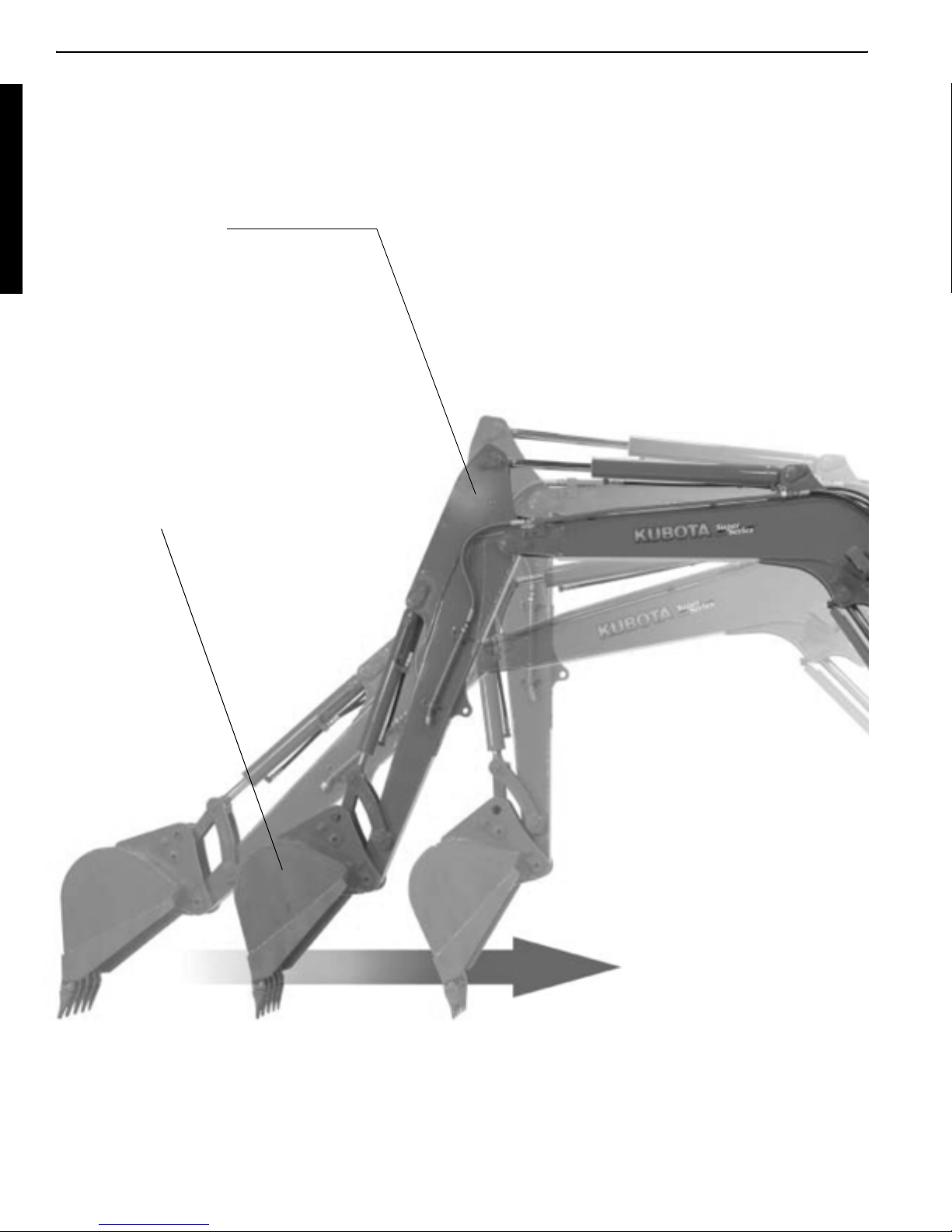
Thumb
Breaker Auger
When a thumb (and tilt bucket) attached, the foot pedal has been used to operate. It has not been
easy for fine control in this way. Such operation can now be finely controlled with your hand (thumb)
and you can ensure more space around your feet.
Service port functions have been tremendously upgraded.
Tilt bucket
II - 22
Page 34

WSM Minor Change II Service Engineering Section
b. Outline of control system
1. Aux. port finger operation
Fine control by finger operation
c Proportionality operation of AUX. port.
d Full open output hold Switch at the time of breaker operation.
e Hand operation ON-OFF Switch. (secure safety priority)
2. Control layout
AUX port hand operation
Breaker Lock sw
Option sw
Travel Hi-Low lamp
Option lamp
Travel Hi-Hold sw
Work lamp sw
Display change sw
Anti Theft Antenna
(EU-version only)
Option: KX91-3S,D or above
Accel
Option: KX41-3SV or above
Hand operation ON-OFF sw
AI-sw
Controller
Knob position signal Right proportional control valve output
Input
Breaker mode select signal
signal
Service mode select signal
CPU
II - 23
Out-
put
Left proportional control valve output
Page 35

WSM Minor Change II Service Engineering Section
3. Service port system components
Meter panel
Main key
ON
Safety lever
lock switch
Knob switch
o start
Breaker switch
Input
Work
switch
lamp
CPU
EEPROM
S/P
switch
Proportional solenoid valve
Output
Main control valve
Panel
selector
switch
Thumb cylinder
II - 24
Page 36

WSM Minor Change II Service Engineering Section
2
Main pump, P
Cylinder rod,
thumb release
Thumb cylinder
Main controle valve,
service port section
Cylinder bottom,
thumb crowd
p
Pilot pump, P
c. Hydraulic circuit diagram
PWM current
PWM current
II - 25
Page 37

WSM Minor Change II Service Engineering Section
d. Knob structure and function
The knob has a built-in IC chip that is different from that for potentiometers.
1)Service mode:Press the center switch of the meter panel to call the service mode.
2)Knob control: Shift the knob to L or R direction to call two way PTO operation.
3)Breaker operation:Press the back button of the knob to call the breaker mode.
1. Structure of knob switch
+5 V
PROPORTIONAL OUTPUT
GND
Horn SW
Breaker SW
ELECTRIC CIRCUIT
4
3
2
1
8
7
6
5
RED
WHITE
BLACK
BLUE
GREEN
YELLOW
GRAY
1
3
2
4
7
6
5
(1)
(2)
(1) Knob switch (2) Horn switch
(3)
(3) Breaker switch
II - 26
Page 38

WSM Minor Change II Service Engineering Section
2. Basic operation of the knob
1) With the key on
When the key is on, the system gets started out of
the service mode OFF-position.
In other words, the knob is not operative. (This is for
safety.)
2) Service mode
Press the center switch of the meter panel, and the
center LED indicator lights up and the system gets in
the service mode. Now the knob is operative. Move
the knob to the left for the thumb to grasp an object.
Move it to the right for the thumb to release it.
3) Breaker mode
The breaker mode is enabled while in the service
mode. Press the breaker switch on the back of the
knob to activate the breaker. The main pump fully
feeds the fluid to the breaker. If the thumb is
attached in place, the main pump feeds the full
amount of fluid from the service port to the thumb
cylinder.
<Breaker switch function>
(1) Push the S/P switch on.
(2) Press the breaker switch.
(3) Breaker starts pounding.
(4) Press the breaker switch again.
(5) Breaker stops.
4) Releasing the breaker
There are three methods to release the breaker operation.
(1) Press the breaker switch again to stop the breaker.
(2) Press the service port switch to off position. (The center LED indication goes off.)
(3) Or, move the knob for over 0.2 second.
(4) Or, lift up the safety lock lever.
(5) Turn the main key to off position.
II - 27
Page 39

WSM Minor Change II Service Engineering Section
3. Flow chart; Service port operation
Key
ON
No
No
Is safety lock lever
down position?
Yes
Service port switch
ON
Service port switch lamp
lights up
Is breaker switch ON?
Yes
Breaker starts.
OFF
No service port operation
Yes
Is knob switch shifted?
Yes
Thumb cylinder
starts moving.
1) Press breaker switch on again?
2) Move the knob switch?
3) Raise the safety lock lever?
4) Main key off?
One of above operations?
Breaker stops
While breaker is working;
Release the knob switch
to neutral.
Thumb cylinder stops.
Yes
II - 28
Page 40

WSM Minor Change II Service Engineering Section
4. S/P switch (service port switch)
<Function chart>
(1) Main key
(2) S/P switch
(3) Service port
function
(4) Safety lock
lever
(5) Warning lamp
buzzer
ON
OFF
Push
Effective
Non-effective
Up
Down
(5 ~ 6 sec.)
Service port switch (S/P sw) in the middle bottom
on the meter panel controls the service port functions, such as thumb switch and breaker switch.
In order to get the service port function, first push
this switch and then control the two switches on
the knob lever.
(1) Service port switch
II - 29
Page 41

WSM Minor Change II Service Engineering Section
5. How the knob switch works
1) Let's suppose that the breaker has been released. To call the breaker mode again, it is necessary to press the back button (breaker switch) of the knob. (This is for safety.)
2) To release the breaker, just move the knob. This is highly convenient.
3) Let's say that you have forcefully moved the lever to operate the other functions, such as boom
up or down or etc. The knob may be momentarily shaken, which may fluctuate the voltage and
unnecessarily release the breaker. To avoid this, the knob must be moved for over 0.2 second
to release the breaker operation. Just for reference, the knob does not tilt for over 0.2 second
under usual lever control conditions.
6. Breaker operation
(1) Main key
(2) Safety lock lever
ON
o start
down
(3) Meter panel controller
ON
(4) Server port switch pushed
(8) Knob switch
ON
(6) Breaker switch
(7) Breaker
(5) Proportional control
solenoid valve
Note: When the safety lock lever is up position, all switches of service port switch, breaker switch and
knob switch don’t function at all. This is also for safety purpose.
Therefore, once the safety lock lever is shifted up while service port operation, breaker or
thumb cylinder stops.
When to start the breaker again, first shift down the safety lock lever, press ON the service port
switch and press the breaker switch. Safety lock switch has the priority for the safety.
II - 30
Page 42

WSM Minor Change II Service Engineering Section
7. Interrelation among current, pressure and flow
6DPSOHGDWD7KXPEFODPS%RWWRPVLGH$SRUWOHIW
0,1USP$
0$;USP$
@
Â
3LORWVHFRQGDU\SUHVVXUH>NJ IFP
&XUUHQWP$
2LOIORZDPRXQWOPLQ2LOIORZDPRXQWOPLQ
3LORWVHFRQGDU\SUHVVXUH>NJÂIFP@
&XUUHQWP$
Note: Above charts are just the sample figures to illustrate the interrelation among the three
parameters.
1. Current: PWM current provided from the panel controller.
2. Pressure: Secondary pilot pressure delivered from S/P solenoid valve.
3. Flow: Oil flow amount supplied to the thumb cylinder.
II - 31
Page 43

WSM Minor Change II Service Engineering Section
e. Initial settings of the knob
1. Set-up and adjustment of service port
This new finger control service port system requires three types of set-up and adjustment procedures.
Items to set-up When
Knob initial set-up 1. Knob change
2. S/P valve change
3. Meter panel change
S/P valve start-point set-up 1. S/P valve change
2. Main control valve change
3. Pilot pump change
4. Hydraulic actuator change
Manual feeling adjustment 1. Hydraulic actuator change
2. Operator change and feeling change
2. Purpose
Three settings (right and left ends, and neutral) of the knob are kept in the meter controller’s memory. Note that there are fluctuations from knob to knob.
The knob has been factory-set at Hirakata Factory or KBM. When the meter, the knob or the proportional control solenoid valve has been replaced, the knob settings must be manually reprogrammed. If not reprogrammed, the thumb may get activated even in neutral or slowly move even
at the right end.
The meter memory keeps the following data in the EEPROM addresses
u 8 = 8184 then 5 V.
1023
But actual data varies as follows.
Address 45: Left end
Address 46: Neutral
Address 47: Right end
o
o
o
0.4 a 0.8 V
2.4 a 2.8 V
4.40 a 4.80 V
<Knob shift amount and output voltage>
Voltage
4.5 V (Address 47)
2.5 V (Address 46)
0.5 V (Address 45)
Left end Right end
Neutral
Knob shift amount
(Knob shift angle)
II - 32
Page 44

WSM Minor Change II Service Engineering Section
3. Background and meaning of knob initial set-up
1) The output voltages at the neutral, rightmost and leftmost positions of a knob are entered as initial settings. Accordingly, correlation between the knob's right-left shift and the output voltage is
stored in microcomputer memory.
2) The voltage generated by the knob's movement is converted by the microcomputer to a PWM
control current. In this way, ordinary operations can be carried on under proportional control.
3) Also the voltages at the neutral, rightmost and leftmost positions of a new control knob are
entered as initial settings in microcomputer memory. Such data serves to control the output
voltage in proportion to the knob's movement.
4) Suppose that you have replaced a control knob but forgotten to make its initial settings. The
previous knob's data, still in microcomputer memory, may be slightly different from new entries.
This may cause different operating feelings.
5) These settings can be made with the key on. Thanks to the built-in temperature compensation
function, there is no problem with ambient temperatures in making the settings.
FYI (For Your Information)
1. Knob switch and Hall element (IC chip)
The knob switch has a temperature-compensated Hall element incorporated. The Hall element consists of a magnet and a coil as shown below. A kind of sensor, this switch has the tilt angle Éý,
which changes the quantity of magnetism. This quantity is converted to voltage. The input voltage is
set at 5 V maximum. With the knob switch at neutral position, the output is about 2.5 V.
2. Hall effect
Let's suppose, as shown in Fig. 1,
that a current is applied to a rectan-
Magnetic flux B [T]
gular solid and a magnetic field is
added perpendicular to the direction
of current. There will be a voltage
that is perpendicular to the direction
Length
T [m]
Voltage
of current as well as to the direction
of magnetic field. This phenomenon
is called the Hall effect, and the voltage thus generated is called the Hall
voltage.
Current I [A]
This effect was discovered by American physicist Edwin H. Hall in 1879.
The effect has the nature of taking
place very frequently with semicon-
Fig. 1 Hall effect
ductors, but rarely with conductors.
3. Hall element
The Hall effect is discussed above. The Hall element includes semiconductors that produce the Hall
effect. Given that the effect takes place very frequently with semiconductors, but rarely with conductors, semiconductors are used to make the Hall element.
Here are the materials to make the Hall element.
- Silicon (Si)
- Germanium (Ge)
- Gallium arsenide (GaAs)
- Indium arsenide (InAs)
- Indium antimonide (InSb)
V [V]
II - 33
Page 45

WSM Minor Change II Service Engineering Section
f. S/P valve start point setting
1. Performance characteristics profile: Knob shift amount vs Output current
Current
Proportional control valve BProportional control valve A
Right end
Knob
Left end
950 mA
450 mA
Neutral
1) A dead zone is provided to keep the thumb intact in neutral. Some margins are also given to
start the thumb at each end.
2) The right-end, neutral, and left-end settings of the knob are presupposed to be in memory.
3) The profile is flexibly modifiable even for maximum engine rpm and idling speed. When the
engine runs at middle speed, for example, the average is determined from the idling map and
maximum map and finally outputted.
4) Suppose that the thumb starts moving at the current of 500 mA. The knob's operating map must
begin with 450 mA because it is necessary to provide an inching zone and give better feeling.
5) At the 500mA level, however, there could be fluctuations due to the control valve, proportional
control valve, hoses and other factors. The meter keeps the initial map and performs as well,
but the inching zone might be longer or shorter depending on the machine.
6) The starting point setting is made to cope with such problem. In the setting mode, the meter
shows the current gradually higher from 450 mA. When the thumb starts moving, the operator is
supposed to press and release the button twice for releasing and grasping of the thumb. The
meter memorizes the then setting.
Address 48:
Address 49:
o
o
Release R Deviation
Grasp L Deviation
The following correction is made for control.
Current
950 mA
450 + (The value in the address 49) 450 + (The value in the address 48)
Left end
Neutral
Proportional control valve BProportional control valve A
Right end
Knob
II - 34
Page 46

WSM Minor Change II Service Engineering Section
7) Service engineers do not notice, but at Hirakata
Factory and KBM, the starting point has been
measured at the service port (red pressure measuring port for North America and Europe) and
fluctuations have been put in the meter memory.
At the manufacturing plants, however, the
machine is not equipped with any thumb attachment. Actually, the starting point is expected to
be measured locally. It would take dealers trouble.
At the manufacturing level, therefore, a pressure
take-out plug is prepared. Although a thumb is
not attached, a current flows to the proportional
control valve and the pressure level changes at a
certain point. This pressure level is detected and
put into memory.
Note: 450 mA and 950 mA are default values
before setting in the factory.
Actual value may differ model by model
(1) Pressure port
and machine by machine after the factory
setting up.
8) Fortunately, the dealers are expected to do just the following in the field
(1) Usually Just install the attachment (Thumb) and
connect the service port hoses.
(2) When the meter is replaced Make the knob initial setting
and the starting point setting.
(3) When the knob is replaced Make the knob initial setting.
(4) When the proportional
control valve replaced
Make the starting point setting,
knob initial setting
The above knob initial setting and starting point setting are required. Otherwise the performance may be unstable depending on finish accuracies of
the component parts.
II - 35
Page 47

WSM Minor Change II Service Engineering Section
2. Background and meaning of start-point setting
1) The purpose of this setting is to keep the knob's operating force of starting the attachment
(thumb cylinder) constant whether the engine runs idle or at maximum speed.
2) The proportional control valve's start-point is activated when you have slowly moved the knob
to start the attachment that is connected with the service port circuit.
3) The knob's action point is referred to in some different factors: knob's movement, output voltage, controller's output PWM current, proportional control valve's hydraulic pressure, pilot secondary pressure of service port main control valve, and hydraulic pressure of attachment
(thumb cylinder, for example).
4) The start-point setting works as follows. When a component of the service port system line has
been replaced, the component with its slightly different individual behavior pattern may delicately affect the line's final output. To compensate such deviation, the initial setting (star-point
setting) must be entered in the controller.
5) The following factors are important in affecting the start-point.
(1) Oil temperature
(2) Engine rpm
(3) Proportional control valve
(4) Main control valve, service port section
(5) Service port load fluctuations
6) These factors are therefore considered for the start-point setting.
(1) Oil temperature
(2) Engine rpm
(3) Proportional control valve
(4) Main control valve,
o
50 qC
o
Idling, Maximum
o
At each replacement
o
At each replacement
service port section
(5) Service port load fluctuations
o
Basically it is preferable to make the setting for
each attachment. If it does not feel unusual,
however, it can be up to the user's judgment.
II - 36
Page 48

WSM Minor Change II Service Engineering Section
3. Illustration of the start-point setting
Voltage fluctuation signal
according to the knob's
PWM current
Pilot secondary pressure signal
S/P section
Main hydraulic line
movement
Move the knob, and you will find the point where the thumb cylinder starts moving. Just when the
cylinder gets activated, press the selector switch. Do this for the right and left movements of the
knob.
Does control start when the start-point has been reached?
]
2
Ps [kgf/cm
[mA]
Pilot secondary pressure
when the thumb cylinder
starts moving.
[mA]
Input current when
the thumb cylinder
starts moving.
Knob movement [T]
II - 37
Page 49

WSM Minor Change II Service Engineering Section
4. Concrete behavior at the start-point setting
PWM input
to the solenoid valve
(mA)
Pilot secondary pressure
l
R,
full stroke
Machine B
Standard
Machine A
Ps
Pilot Secondary pressure current
]
difference a
i
T
. As
s
difference b
L,
full stroke
T
:standard knob angle to start S/P
s
T
:Machine A knob angle to start S/P before set-up.
a
T
:Machine B knob angle to start S/P before set-up.
b
i
l
θbθsθ
a
Knob control angle: θ
Set-up target is to start attachment (thumb cylinder) at the constant same knob control angle,
shown in above Fig., machine A starts at
In order to get both machines start at
T
, machine B at Tb.
a
T
, controller outputs the PWM current by adding the difference a
s
or by subtracting the difference bi to machine A and B respectively.
Start point set-up is to test the difference a
, bi and input their data to the controller. So that the control-
i
ler can calculate and output the required amount PWM current to start the attachment at the same
T
knob control angle
.
s
Why set-up at engine Max. rpm?
For safety purpose, start-up point is earlier at engine Max. speed than at idle speed.
i
II - 38
Page 50

WSM Minor Change II Service Engineering Section
5. S/P valve initial set-up flow chart
<Machine’s operation cycle> <Operator’s action>
For the right direction, enter the
knob's output voltage with the
engine at maximum rpm.
Controller
PWM current is
outputted.
The proportional control solenoid
valve spool starts shifting.
When the thumb cylinder starts
moving, press the service port
button on the panel.
Enter the start-point output voltage in the controller.
Do the same for the left direction.
Setting complete.
Now the controller's PWM output current has been set so that the thumb
Visually make sure that the cylinder has started moving.
The main control valve
spool starts shifting.
The thumb cylinder starts moving.
cylinder starts moving at a preset
knob position (an input at maximum
rpm). This cylinder behavior occurs
at any engine speed.
Precisely speaking, controller’s output current is the same at a preset
knob position.
Therefore, the solenoid force of the
S/P valve and the secondary pailot
pressure are identical.
So spool shift amount of the main
control value section is the same.
But as the main pump delivery rate
varies and so thumb cylinder’s starting point varies according to the
engine speed to same extent.
Then why do the start-up setting at
max. engine speed?
For safety.
II - 39
Page 51

WSM Minor Change II Service Engineering Section
g. Manual feeling setting
1. Outline of manual feeling setting
Basically, the thumb is supposed to move smoothly by the starting point setting, but one may feel
poor. To ensure good feeling, therefore, this mode is added.
Setup
Service port feeling adjust
Right
Slow -12 Fast
n
(This value x 5 mA) is added to the map.
Current
Proportional control valve BProportional control valve A
( Fine adjustment of 450
+ The value of the address 49
+ Fine adjusting value of grasp L )
Right end
Knob
Left end
950 mA
Neutral
The right and left fine adjustment values are put to addresses 62 and 63, respectively, in the memory.
These values will become zero when the starting point setting of a model has been made.
When address 62 is set at "5", the setoff will be 25 mA: when set at "FFFF", the setoff will be -10
mA.
II - 40
Page 52

WSM Minor Change II Service Engineering Section
2. Knob shift amount and output current
Then actually move the knob, and ensure a good current-duty map at the current of 500 mA and
the oil-flowing current.
The proportional control valve, however, is rather unstable in its temperature characteristics (temperature vs. resistance). Such control is still required. (Dark current theory)
Output Current
[mA]
950
850 + (Add.49) +(Add.68)
(Initial value)
+ (Add.49) +(Add.68)
0
21819
Knob shift amount
II - 41
Page 53

WSM Minor Change II Service Engineering Section
Finish
Key off
o
In case of AI-version only
Finish
S/P port moves left
Finish
Set up machine
Key off
Push selector sw
Key off
Diagnosis
Set up AI
o
Engine start
o
o
o
S/P knob neutral
o
S/P knob left end
o
S/P knob right end
o
S/P port moves right
Push selector sw
o
Engine max
o
S/P actuator middle
o
S/P left speed
+ slow 12 fast -
o
S/P right speed
+ slow 12 fast -
o
Engine max
o
English
o
:: p
ppp
1. Outline (S/P knob, S/P valve, S/P feeling adjust)
KX91-3
KX101-3 French Set up
:: Other menu
h. Panel display operation flow chart
p
Set up overheat
warningpSimple modepSet up S/P knob
o
Lift up safety lever
o
o
Down the safety lever
o
p
Set up S/P valve
II - 42
o
Down the safety lever
o
Set up
S/P feeling adjust
p
Back tier
p
Page 54

WSM Minor Change II Service Engineering Section
2. Display flow chart with photo
o
o
KX91-3
English
1. Turn the starter key to ON
(AC position) while pressing
the display selector switch on
the panel.
Then the machine model
comes on the display.
2. Push the display selector
switch long, then language to
be selected comes on the
display.
KTC and KTA version display
only English. KCL indicates
English or French for selection.
EU version has eleven languages to be selective.
o
Diagnosis
Set up
3. Push the display selector
switch long, then the display
moves to “Diagnosis”.
p
4. Push the display selector
switch short, then the display
moves to “Set up”.
II - 43
Page 55

WSM Minor Change II Service Engineering Section
o
Engine start
o
Set up machine
5. Push the display selector
switch long, then the display
indicates to “Engine start”.
6. Push the display selector
switch long, then the display
moves to “Set up machine”.
Set up overheat
warning
p
Simple mode
p
7. Push the display selector
switch short, then the display
moves to “Set up overheat
warning”.
Skip this menu.
8. Push the switch short, then
the display shows “Simple
mode”.
Skip this also.
II - 44
Page 56

WSM Minor Change II Service Engineering Section
9. Push the display selector
Set up S/P knob
switch short, the display indicates to “Set up S/P knob”.
For the Setting-up of the service port knob initialization,
press the display selector
switch long. This initialization procedure will be illustrated in another pages.
p
10.Push the display selector
Set up S/P valve
switch short, the display indicates “Set up S/P valve”.
p
Set up
S/P feeling adjust
p
Back tier
11.Push the display selector
switch short, the display indicates “Set up S/P feeling
adjust”.
12.Push the display selector
switch short, the display
returns to “Set up machine”.
Push the display selector
switch long, the display
returns to “Set up”.
Note: In one of AI-version machine, the display shows “Set up AI” when the display selector switch
is pressed long at “Engine start”.
II - 45
Page 57

WSM Minor Change II Service Engineering Section
3. Knob initial set-up
p
Set up S/P Knob
p
S/P knob right end
p
S/P knob left end
1. The LCD display shows as
“Set up S/P knob”.
2. Push the display selector
switch short, then the display
shows “Lift up safety lever“.
This is for safety purpose.
3. Lifting up the safety lock
lever moves to the display of
“S/P knob right end”.
4. Push the display selector
switch short, then the display
shows “S/P knob left end”.
p
S/P knob neutral
p
Finish
Key off
5. Push the display selector
switch short, then the display
shows “S/P knob neutral”.
6. Push the display selector
switch short, the display indicates “Finish Key off”.
It means knob initialization
has been completely.
II - 46
Page 58

WSM Minor Change II Service Engineering Section
4. S/P valve initial set-up
1. As instructed in page ***,
Set up S/P valve
p
Down the safety lever
you’re required to reach the
display shows as “Set up S/P
valve”.
Safety precaution!
Engine is running.
2. Shift down the safety lock
lever down to control the service port attachment.
p
S/P actuator middle
p
Engine max
3. Get the S/P actuator to the
middle point of the full stroke
by shifting the S/P knob.
4. Set the engine at the max.
speed.
p
II - 47
Page 59

WSM Minor Change II Service Engineering Section
5. Push the display selector
S/P port moves right
Push selector sw
switch at the moment that the
actuator cylinder starts moving to extend.
Note: In case of thumb cylinder,
“right” indicates the cylinder to extend. “left” indicates to retract.
p
6. After being pushed in the
S/P port moves left
Push selector sw
above, automatically the display moves over “S/P port
moves left”.
Therefore, push the display
selector switch at the
moment that the actuator cylinder starts moving to retract.
Finish
Key off
p
7. Then the display changes to
“Finish Key off”.
II - 48
Page 60

WSM Minor Change II Service Engineering Section
5. S/P operational feeling adjustment
p
Set up
S/P feeling adjust
p
Down the safety
lever
1. As instructed in page ***,
you’re required to reach the
display shows as “Set up S/P
feeling adjust”.
Safety precaution!
Engine is running.
2. Shift down the safety lock
lever down to control the service port attachment.
p
Engine max
p
3. Set the engine at the max.
speed.
II - 49
Page 61

WSM Minor Change II Service Engineering Section
S/P right speed
+ slow 12 fast -
pn
S/P left speed
+ slow 12 fast -
p
4. Slowly slide the S/P knob
switch to right direction and
check the actuator’s starting
points.
If it starts moving too quick,
get it slow by pressing the
work lamp switch, left end
button.
If it starts moving too slow,
get it fast by pressing the
service port switch, middle
button.
Digit number indicates the
feeling level of slow or fast.
Pressing the display selector
switch short, switches the
display to adjust the left or
right speed.
Finish
Key off
After completing the feeling
adjustment, just set the key
off.
II - 50
Page 62

WSM Minor Change II Service Engineering Section
i. Proportional control solenoid valve (S/P valve)
1. Outline
This valve is the combination of electro magnetic solenoid valve and hydraulic reducing valve.
Ordinally solenoid valve is controlled ON-OFF by battery 12 V direct current. But this valve is controlled by the PWM (pulse width modulation) current supplied from the micro computer controller
incorporated in the meter panel.
Valve spool function is basically the reducing valve same as the hydraulic pilot control valve, normally used for the lever control. Difference is as follows.
The hydraulic pilot control valve regulates the pilot pressure, balancing to the operator’s manual
force. This S/P valve is regulated by the PWM current. In either case, this pilot pressure is socalled the secondary pilot pressure to control the spool stroke of the main control valve.
II - 51
Page 63

WSM Minor Change II Service Engineering Section
2. Structure and function
(Hydraulic symbols)
A
P
Solenoid magnetic force Spring load Pressure applied
F
sol
PA T
F
sp2
Fp = P
A
a
II - 52
Page 64

WSM Minor Change II Service Engineering Section
3. Function theory
Behavior of proportional valve
Balance of proportional valve forces
PA T
P
a
Reducing valve spool
hydraulic pressure force
sp1
Proportional solenoid
magnetic force
Transfer
spring
sp2
Behavior of solenoid proportional valve
Definitions of values
F
: Solenoid magnetic force generated according to current
sol
F
= C1 x I (C1 and I are solenoid's intrinsic constant and current, respectively.)
sol
: Solenoid's spring load
F
sp1
F
: Valve's spring load (constant during pressure control)
sp2
: Pressure applied by setup area difference
F
p
= A x Pa (A and Pa are setup area difference and pressure at port A, respectively.)
F
p
P: Primary pilot pressure from the pilot pump controlled by the unload relief valve
P
: Secondary pilot pressure to control the main control valve spool
a
A
Pressure receiving
area difference
Balance of forces
The balance of forces for the valve spool (see above) is expressed like this.
F
sol
+ F
sp1
= P
When the left term is greater, the spool moves rightward and ports P and A open one after the
other.
When the right term is greater, the spool moves leftward and ports A and P open one after the
other.
The above expression is rearranged as follows.
+ F
F
sol
=
P
a
- F
sp1
F
+ F
sol
a
sp2
sp1
A
A + F
= P
- F
sp2
A
a
sp2
II - 53
Page 65

WSM Minor Change II Service Engineering Section
Spool control performance I-P curve
Pa (MPa)
20
3.0
F
+ F
sol
- F
sol
sp2
15
F
10
Solenoid force (N)
F
+ F
5
sol
= P
00.511.5
Current (A)
sp1
a
sp1
2.0
1.0
Spool opening area
21 210
)
10
2
8
6
4
Spool opening area (mm
2
A - T P - A
Spool opening stroke (mm)
Suction prevention
against interference
(Opening area symmetrical
right and left on standard type)
A - T: Actuator to tank
P - A: Pump to actuator
II - 54
Page 66

WSM Minor Change II Service Engineering Section
j. Other controls
1. Model number display
Displayed in the case of AI specifications.
2. Automatic service port identification
With the key on, a current of 250 mA or so is made to flow in the service port proportional control
valve. When feedback is available, the machine is of service port type. If not, the machine has no
service port.
This automatic identification is added because some machines have service port and the others
have not. It should be noted that the map profile is different from model to model and from destination to destination (Europe and North America).
3. Fool-proof control.
When the service port sensor reads below 0.25 V or over 4.75 V for 0.2 second:
Nothing displayed, however, out of the service mode.
4. Idle-up control
The idling speed increases by 150 rpm when the water temperature drops below 30 centi-degrees
(Reason: Even at the same governor position, the engine speed drops about 150 rpm at the temperature of -18 centi-degrees.)
5. Compressor control
When the compressor is on, the idling speed is raised by 150 rpm.
The idea is as follows.
If the compressor is repeatedly turned on and off and kept off for 3 seconds, the idling speed gets
back to its original rpm. In this way, the AI motor can be kept from getting activated many times.
(Reason: If the compressor is on and the alternator barely generates power, the battery, if connected to an external load, may fail to work.)
II - 55
Page 67

WSM Minor Change II Service Engineering Section
k. Troubleshooting
1. Troubleshooting
Following troubleshooting is based on below preconditions.
Therefore: 1. Hydraulic oil quality and quantity are normal.
2. Hydraulic pump P
3. All the functions except service port system are normal.
Fail symptom Suspected causes Check points
a. Service port attachment does
not work at all. (Thumb's failure to move in both directions;
Breaker's failure to crush;
Auger's failure to turn)
b. Thumb does not work in one
direction at all.
c. Service port attachment
moves slower than specified
in both directions.
d. Service port attachment
moves slower than specified
in one direction.
e. S/P attachment moves at neu-
tral position of knob switch
, P2, P3, P4 are OK.
1
1. Knob switch harness is cut or coupler
is disconnected.
2. S/P valve harness is broken or coupler is disconnected.
3. S/P valve spool is stuck inside. S/P valve spool.
4. Main S/P valve spool is stuck inside. Main control valve S/P section.
5. S/P valve pressure is quite low in both
side.
1. S/P valve solenoid harness is broken
one side.
2. S/P valve spool is stuck inside. S/P valve spool.
3. Main control valve S/P section is
stuck one side.
4. Knob switch initial setting error. Knob switch initial setting.
5. S/P valve pressure is quite low in one
side.
1. S/P valve start-up setting error. Do S/P valve start-up setting.
2. Current amount from the controller is
not enough.
3. S/P valve spool moves heavy and
slow.
4. S/P valve pressure is low in both
sides.
5. Main control valve S/P section spool
won’t shift at full stroke.
1. Knob switch initial setting error. Do knob switch initial setting.
2. S/P valve start-up setting error.
3. Manual feeling setting error. Do manual feeling setting.
4. Main control valve S/P section spool
one side won’t shift at full stroke.
1. Knob switch initial setting error. Do knob switch initial setting.
2. S/P valve spool is stuck at one side. S/P valve spool.
3. Main control valve S/P section spool
is stuck at one side.
Knob harness, fuse and switch coupler.
S/P valve harness and coupler.
Test the S/P valve pressure.
S/P valve harness.
Main control valve S/P section.
Test the S/P valve pressure.
Knob switch initial setting.
Meter panel (Controller) output current.
S/P valve spool.
Test the S/P valve pressure.
Main control valve S/P section spool.
Do S/P valve start-up setting.
Main control valve S/P section spool.
Main control valve S/P section spool.
II - 56
Page 68

WSM Minor Change II Service Engineering Section
II - 57
Page 69

WSM Minor Change II Service Engineering Section
C. Hydraulic system modification
a. Outline
In order to improve further “Load Sensing Performance”, pump and control valve have been changed
in several parts. Main parts of minor change are as follows.
1. Hydraulic pump: KX121-3SD, 161-3SD, U45-3D
(1) Valve plate opening performance improved
End milling finish to V-shape notch
(2) Piston shoe type change
Multi-pad type to single-pad type
(3) Cylinder block center spring foree upgraded
(4) Swash plate shape change
(5) Swash plate pin shape change
(6) PC regulate spool pin dia. I3.5 o I3.2
Horse power spring change
(7) LS valve compact size
PC orifice I0.6 added
2. Control valve: KX121-3SD, 161-3SD, U45-3D
(1) Damper chamber added in the unload valve (orifice I1.2)
(2) In order to achieve the stable response of PLS signal line;
I1.0 orifice added in valve’s PLS port plug.
Hose volume (1/4” u350mm length) added.
(3) Shuttle plate change;
Outer dia is approx. 20Pm larger in minor change
(4) Compensation spools of arm, bucket and swivel;
orifice machining deleted.
3. Travel motor: KX121-3SD, 161-3SD, U45-3D
(1) Moter swash plate: Light weight type
(2) Hi-Low piston: Shape change
(3) Thrust plate: Shape change
(4) Sun gear: Snap ring removed
(5) Ring nut: Casting iron to steel iron
(6) Reduction gear case drain port size: G 1/4, hex. 6 o G 3/8, hex. 8
4. Role of hose volume (1/4” u350mm)
The hose volume control that is attached on the control valve serves as a sort of damper. At a start
of operation in particular (to start traveling, for example), it is effective in avoiding a sudden surge
pressure and preventing the machine from starting with a jerk. In other words, violent fluctuations
of load pressure can be eased, which improves the operator’s control feeling. Below discussed is a
theoretical explanation of the hose volume control behavior.
At very low temperatures, the throttling effect of the orifice in the system is greatly affected, usually
causing delays in response. Let’s suppose shifting the travel lever forward under low temperatures, for example. Possibly the machine may fail to respond quickly or it may take too much time
to get started. In such cases, preferably remove the hose volume control for better damping effect,
and install the plug attached on previous models. Keep in mind, however, that the higher the oil
temperature rises, the quicker the reaction becomes.
II - 57
Page 70

WSM Minor Change II Service Engineering Section
b. Hydraulic pump: KX161-3s, KX161-3D
1. Pump installation: KX161-3SD, U45-3D
(1) Adapter tightening torque
P port (G3/4) 117.6 ~ 127.4N
P
, PLS, CH port (G1/4) 24.5 ~ 29.4Nm (2.5 ~ 3.0kgfm)
PS
P
port (G3/8) 49.0 ~ 53.9Nm (5.0 ~ 5.5kgfm)
P
m (12.0 ~ 13.0kgfm)
II - 58
Page 71

II-59
WSM Minor Change II Service Engineering Section
2. Piston pump: KX161-3S (PP), KX161-3D (EU), U45-3D (EU, KTA)
63(&,),&$7,21
Page 72

II-60
WSM Minor Change II Service Engineering Section
7,*+7(1,1*72548(
Page 73

II-61
WSM Minor Change II Service Engineering Section
3. Specifications of pump
Model: PSVL-54CG Piston pump power constant characteristics: KX161-3D, U45-3D
Piston pump power constant characteristics: KX161-3S
Item Specifications Remarks
Basic spec.
Displacement Piston pump
13.0 ~ 54.0 cm
3
/rev
Gear pump -
Pilot pump
4.0 cm
3
/rev
Gear pump
Direction of rotation Right (Clockwise) As seen from the shaft
Pilot relief set press 3.9 MPa
Drain pressure Less than 0.098 MPa
Section press -0.04 ~ 0.07 MPa
HYD. oil: VG46, HYD. oil temp: 50 qC,
2450 rpm
Filter 10 Pm equivalent
Straner 150 mesh
HYD. contamination classes W ithin NAS 9
Customer spec.
Engine horse power
KX161-3D, U45-3D 28.7 / 29.4 kw
KX161-3S 34.6 kw (Gross)
Shaft speed
KX161-3D, U45-3D
1000 ~ 2250 rpm
Max. unloaded:
less than 2450 rpm
KX161-3S
1000 ~ 2200 rpm
Max. unloaded:
less than 2450 rpm
Max. working Pressure
Piston pump 24.5 MPa Piston pump pressure: P
Gear pump -
Pilot pump 4.12 MPa
Pilot pump pressusre: P
p
Max. pump flow
Piston pump 118.8 (121.5) L/min at 2200 (2250) rpm
Gear pump Pilot pump 8.8 (9.0) L/min at 2200 (2250) rpm
Max. input torque
KX161-3D, U45-3D 108.0 (108.0) Nm at 2200 (2250) rpm
KX161-3S 118.0 Nmat 2200 rpm
HYD. oil
Oaphny super hydro 46
Shell terras K46
VG46 equivalent
Hydraulic oil temperature at tank
Ordinary use: -10 ~ +80qC
Short time use: -20 ~ +90qC
Drive system Input shaft: Direct drive No radial load
General spec.
All efficiency (Typical value) 79 % VG46, 50 qC, 2200 rpm, 13.7 MPa
Control method
Power constant control
Load sensing control
Proportional LS control pressure
Horse power setting 24.8 kw at 2200 rpm
Max. pump flow (Piston pump) 118.8 r 2.5 L/min VG46, 50 qC, 2200 rpm, P=Min.
Max. input torque 105.1 ~ 108.0 Nm at 2200 rpm
Pilot pump flow Mor than 8.0 L/min
VG46, 50 qC, 2200 rpm, P
0
=4.12 MPa
LS control pressure 1.45 r 0.05 MPa
VG46, 50 qC, 2200 rpm, P
LS
=9.8 MPa
Proportional LS control pressure
1.45 r 0.05 MPa (at 2200 rpm)
0.73 r 0.1 MPa (at 1000 rpm)
VG46, 50 qC, P
LS
=9.8 MPa
SHAFT SPEED 2200rpm
TOTAL INPUT TORQUE 108.0
-2.9
PRESSURE [MPa] DELIVERY FLOW [L/min] PRESSURE [MPa] DELIVERY FLOW [L/min]
PA0= 0.0 QA0= 118.8 PB0= 0.0 QB0= 118.8r2.5
PA1= 9.2 QA1= 117.8 PB1= 7.8 QB1= 117.2r2.5
PA2= 15.3 QA2= 66.0 PB2= 10.8 QB2= 104.1r4.0
PA3= 24.5 QA3= 33.5 PB3= 12.7 QB3= 87.0r4.0
PB4= 16.6 QB4= 61.4r5.0
PB5= 23.5 QB5= 37.0r5.0
SHAFT SPEED 2200rpm
TOTAL INPUT TORQUE 108.0
-2.9
PRESSURE [MPa] DELIVERY FLOW [L/min] PRESSURE [MPa] DELIVERY FLOW [L/min]
PA0= 0.0 QA0= 118.8 PB0= 0.0 QB0= 118.8r2.5
PA1= 10.7 QA1= 117.3 PB1= 10.0 QB1= 117.3r2.5
PA2= 16.7 QA2= 72.0 PB2= 12.0 QB2= 109.0r4.0
PA3= 24.5 QA3= 43.8 PB3= 15.0 QB3= 85.5r4.0
PB4= 18.0 QB4= 68.8r5.0
PB5= 24.5 QB5= 43.8r5.0
3%4%
3%4%
3%4%
3%4%
3%4%
3$4$
3$4$
3$4$
3$4$
3%4%
3$4$
3$4$
3$4$
3$4$
3%4%
3%4%
3%4%
3%4%
3%4%
3%4%
0
PRESSURE: P [MPa]
DELIVERY FLOW: Q [L/min]
PRESSURE: P [MPa]
DELIVERY FLOW: Q [L/min]
P-Q Curve
P-Q Curve
0
Page 74

II-62
WSM Minor Change II Service Engineering Section
Page 75

WSM Minor Change II Service Engineering Section
1. PP-version (KX161-3S)
c. Control valve
II-63
Page 76

WSM Minor Change II Service Engineering Section
2. EU, KTA-version (KX161-3DS)
II-64
Page 77

WSM Minor Change II Service Engineering Section
3. Third line-version: EU & KTA, KX161-3DS
II-65
Page 78

WSM Minor Change II Service Engineering Section
)
To pump
Hose volume H350
Orifice diameter 1.0
Orifice diameter 0.7
Compensation pulse signal
To pump
Orifice diameter 0.7
Orifice diameter 0.8
Tightening torque: 5±1 N-m
Orifice diameter 1.2
(Before minor change) (After minor change
4. Inlet section; KX121-3SD, 161-3SD
Compensation pulse signal
Section B-B Section B-B
II-66
Page 79

WSM Minor Change II Service Engineering Section
Spool ID marking on the surface
5. Other section, shuttle plate change
II-67
Page 80

WSM Minor Change II Service Engineering Section
d. Accumulator
1. Structure and specifications: PP-version
PP-version has newly adopted the accumulator.
(12)
(1)
(2)
(3)
(4)
(5)
(6)
(1) Valve screw
(2) Protecting cop
(3) Seal ring
(7)
(4) Retainer
(5) Marking
(6) Shell
(8)
(7) Diaphragm
(8) Valve poppet
(9)
(9) Hex. screw 36
(10) Protecting plug
(11) Screw type: G 1/2
JIS B2351 Type 0
(12) The gas pressure po is variable
(10)
(11)
with our charging and gouging set.
Starting torque screw 20 Nm
1) Type code: SB0210-0.32E1/663U-210LH010
2) Manufacture: HYDAC GMBH
3) Specification
(1) Volume : 0.32 L (0.027 us gal)
(2) Permissible max. working pressure :
(3) Charge gas : Nitrogen (N
(4) Charge pressure :
(5) Media : Mineral oil
(6) Allowable pressure ratio
(Max. pressure / charging pressure)
(7) Temperature of oil : -30 q ~ +80 qC (-86 q ~ +176 qF)
(8) Weight : 1.3 kg (2.87 lbs)
(9) Surface treatment : Black primer
210 bar (214 kgf/cm
gas)
2
10±1 bar (10.2±1 kgf/cm2) 1±0.1MPa(145±1.4 psi)
: Under 8 / 1
Example
When charging pressure is set 10 bar, should set
max. pressure under 80 bar for use.
2
) 21 MPa(3047 psi)
II - 68
Page 81

WSM Minor Change II Service Engineering Section
2. Change valve with accumulator: EU-version
2-1 Structure Maker: Hydro control
As for EU-version accumulator, structure and specifications almost all remains same as before.
To swivel joint
To pump P
filter
Swivel motor
Pilot valve(Right)
Pilot valve(Left)
4
2-2 Specifications
1) Max. oil flow : 16 l/min (4.23 Us gal.)
2) Rated voltage and output : 12 V - 18W
3) Coil resistance : 8
:
II - 69
Page 82

WSM Minor Change II Service Engineering Section
3. Accumulator installation: KX91-3S, U35S, U35-3S(KTA)
1) Bolt tightening torque
48.1 ~ 55.9Nm (4.9 ~ 5.7kgfm)
II - 70
Page 83

WSM Minor Change II Service Engineering Section
II - 71
Page 84

WSM Minor Change II Service Engineering Section
4. Accumulator installation: KX121-3S, 161-3S
1) Bolt tightening torque
48.1 ~ 55.9Nm (4.9 ~ 5.7kgfm)
2) Adapter G3/8 tightening torque
37.2 ~ 42.1Nm (3.8 ~ 4.3kgfm)
II - 72
Page 85

WSM Minor Change II Service Engineering Section
KX121-3S is almost same except control valve.
1. Pilot control line: PP-version, KX161-3S
e. Hydraulic system line
II-73
Page 86

WSM Minor Change II Service Engineering Section
2. Pilot control line: EU-version, KX161-3D
II-74
Page 87

WSM Minor Change II Service Engineering Section
3. Pilot delivery line: KX161-3S
II-75
Page 88

WSM Minor Change II Service Engineering Section
.
m (3.8 ~ 4.3 kgfm)
m (6.0 ~ 6.5 kgfm)
m (1.0 ~ 1.15 kgfm)
G1/2 58.8 ~ 63.7 N
Kubota Japan make is almost same among KX91-3S to KX161-3S
(1) Bolt tightening torque: 9.8 ~ 11.3 N
(2) Adapter tightening torque:G3/8 37.2 ~ 42.1 N
4. Pilot filter
II-76
Page 89

WSM Minor Change II Service Engineering Section
5. Pilot control line: KX91-3S, U35S, U35-3S (KTA)
II-77
Page 90

WSM Minor Change II Service Engineering Section
6. Delivery hose: KX91-3S, U35S, U35-3S (KTA)
II-78
Page 91

WSM Minor Change II Service Engineering Section
II-79
Page 92

WSM Minor Change II Service Engineering Section
7. Rotary joint hoses: KX91-3S, U35S, U35-3S (KTA)
II-80
Page 93

WSM Minor Change II Service Engineering Section
m
m)
24.5 ~ 29.4 N
(2.5 ~ 3.0 kgf
')
G1/4
Pipe joint (L, G1/4-G1/4)
(1) Adapter tightening torque
(RC601-6372
m
m)
(5.0 ~ 5.5 kgf
49.1 ~ 53.9 N
')
')
G3/8
Pipe joint (L, G3/8 - G3/8)
(RP201-6181
Pipe joint (T, F2 - F3)
(RC411-6384
8. Change valve
II-81
Page 94

WSM Minor Change II Service Engineering Section
Adapter tightening torqueG1/4:25.0 ~ 30.0 Nm (2.5 ~ 3.0 kgfm)
1. S/P valve
f. Service port (S/P) solenoid valve
II-82
Page 95

WSM Minor Change II Service Engineering Section
2. S/P valve
II-83
Page 96

WSM Minor Change II Service Engineering Section
3. Heat-up circuit
II-84
Page 97

WSM Minor Change II Service Engineering Section
g. Travel motor: KX91-3S: PP-version
In this minor change, KX91-3S, U35S and U35-3S shockless valve spool has been deleted from the
travel motor. Still Kubota’s engineering has achieved the improved feeling at start-up and stop. Here
are the explanation in detail how done.
Improvement of start-up and stop feeling
1. Market demand to the travel motor
1) In-shoe type motor Wheel type motor
2) High speed
3) Traveling feeling
Hi-Low speed change structure
Shockless relief valve
Shockless spool
Anti-void valve
2. Counterbalance mechanism
1) At start-up and while traveling
Fig. 1 shows the circuit diagram when the
motor gets started and keeps running. The
hydraulic oil from the pump at start of the
motor is introduced to port P1. The hydraulic oil flows through the check valve L to
keep the motor running. The hydraulic oil at
port P1 passes through the orifice L to act
against the end of the spool. The spool then
moves to the right against the force of
spring R. The return oil from the motor flows
through the variable orifice of the spool and
port P2, and back into the tank. When the
return oil passes via the spool's variable orifice, a back pressure occurs at port M2. If
the counterbalance spool is slow in motion,
therefore, a higher-than-expected pressure
is applied at port M2 and you may feel a jolt
at the start of the machine.
When the motor stops and the control valve
gets back to neutral, the hydraulic oil from
the pump is cut off and the pressures at
ports P1 and P2 become the same as
shown in Fig. 1. Then, the spool is affected
by the force of spring R and comes back
from the state in Fig. 1 to that in Fig. 2. At
this time, the outlet port M2 is gradually
throttled by the variable orifice. On the other
hand, the motor keeps in motion by the inertia force. This produces a brake pressure at
port M2, by which the motor gradually slows
down and comes to a stop. If the pressure
at M2 would rise violently, the motor would
come to a sudden stop and you would feel a
jolt at the stop.
(2)
(1)
(3)
Fig.1 At start-up and while traveling
(1) Pump
(2) Orifice L
(3) Check valve L
(4) Variable orifice part
(5) Counterbalance spool
(6) Spring R
(7) Control valve
(8) Tank
(4)
(8)
(7)
(5)
(6)
II - 85
Page 98

WSM Minor Change II Service Engineering Section
2) Better feeling at start and stop
To improve the start-up feeling, the counter-
balance spool must be activated quickly to
keep the start-up pressure at port M2 low.
To enhance the stop feeling, on the other
hand, the brake pressure at port M2 should
rise smoothly. In other words, it is important
how well the pressure at port M2 can be
controlled in starting and stopping the
machine.
(2)
(3)
(1)
(4)
(5)
Fig.2 At motor stop
(1) Pump
(2) Check valve
(3) Counterbalance spool
(4) Control valve
(5) Tank
3) Conventional pressure control method
The pressure at port M2 has been so
far controlled by giving better counter-
Pressure [MPa]
Braking started
balance mechanism response and
mounting a relief valve with shockless
function. As illustrated in Fig. 6, the
M1 port pressure
9.8
shockless relief valve is activated utilizing the difference between the pressure receiving area (S1) and spring
chamber area (S2). While the free
M2 port pressure
9.8
piston provided around the relief
housing is moving, the M2 port pressure is held at low level. When the
0
First speed
Second speed
free piston has completely moved, the
relief valve gets activated at a specified pressure. The M2 port pressure is
thus raised in two stages, which
eases possible violent jolts.
Fig. 3 Brake pressure waveform
(with shockless relief valve)
Shockless relief activated
Fig. 7 shows the brake pressure waveform of the travel motor with shockless relief valve. As
clear in this figure, the M2 port pressure is different at a first-speed stop and a second-speed
stop. If the stop feeling is adjusted in matching the shockless action pressure with the M2 port
pressure for second-speed stop, the feeling will not be just right at the M2 port pressure for firstspeed stop. If adjusted for the first-speed stop, to the contrary, the second-speed stop feels
unsmooth. In the existing construction, it is difficult to have both the first-speed and the secondspeed stop feelings equally good.
II - 86
Page 99

WSM Minor Change II Service Engineering Section
4) Improvement of the counterbalance spool performance
The characteristics and responsiveness of
the counterbalance spool's variable orifice
are adjustable to better control the M2 port
pressure. At the start, the spool's spring
force gets weak for the counterbalance
spool to switch over at low pressure. This
makes for smooth start-up. At the stop, the
variable orifice's characteristic settings and
the counterbalance spool's return time are
adjusted to produce the M2 port pressure
smoothly.
The variable orifice characteristics refer to
changes in the counterbalance spool orifice's opening area. As the spool moves, the
opening area changes, which produces a
Orifice's opening area
pressure corresponding to the opening
area. The counterbalance spool's return
time is determined by the spring force and
the orifice opening. The stronger the spring
force and the larger the orifice opening, the
stroke
quicker the counterbalance spool returns. A
weaker spring force and a smaller orifice
Fig. 4 Spool stroke and opening
opening, contrarily, bring back the spool
slowly. As discussed above, the counterbalance spool's orifice characteristics and
return time are preset, and the actual
machine will be matching-tested to achieve
better feeling.
In case of KX91-3, two orifices are incorporated in the pilot line and counterbalance spool has
several holes for the variable orifice function as shown in Fig. 5.
With this variable orifice, spool stroke and opening area of the counterbalance spool is as
shown in Fig. 4.
Orifice 1 Orifice 2
Small holes for variable orifice
FIg. 5 Counterbalance spool and orifices
II - 87
Page 100

WSM Minor Change II Service Engineering Section
5) Performance comparison
)
2
350.0
250.0
150.0
Pressure (kgf/cm
50.0
0.0
0.00 0.05 0.15 0.25 0.35 0.45
Time (sec)
FIg. 6 New Type: High speed
350.0
)
2
250.0
150.0
140.00
)
2
100.00
60.00
Pressure (kgf/cm
20.00
140.00
)
2
100.00
0.00
0.00 0.10 0.20 0.30 0.40 0.50
Time (sec)
Fig. 7 New type: Low speed
60.00
Pressure (kgf/cm
50.0
0.0
0.00 0.05 0.15 0.25 0.35 0.45
Time (sec)
Fig. 8 Previous type: High speed Fig. 9 Previous type: Low speed
As above figures indicate that the previous type shows high peak pressure. New type figures
show comparatively low peak pressure and regulated.
A time to stop is longer by approx. 0.1 second.
In this way, traveling shock amount while ordinally working condition is almost equivalent or a
little better than the previous type.
Pressure (kgf/cm
20.00
0.00
0.00 0.10 0.20 0.30 0.40 0.50
Time (sec)
II - 88
 Loading...